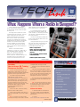
1
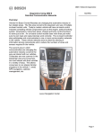
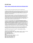
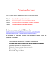
September 2001
Volume 3, No. 9
Some customers may inquire
about replacing the factory radio with
an aftermarket setup or with an uplevel factory unit.
The days when a radio was a selfcontained box are long gone. The first
major change was the use of the
Delphi Entertainment and Comfort
bus. Now, on some of the newest
vehicles, the entertainment system is
integrated into the vehicle’s serial data
network. This means that the radio
must be capable of communicating
over the serial data bus (also called
class 2) with various other modules in
the vehicle.
When a conventional radio is
turned off, it is truly off. A radio unit in
the serial data system, however, only
looks “off” when it is turned off.
Various circuits remain aware of
what’s going on, and will wake up at a
moment’s notice. For instance, the
chimes and OnStar® both use the
radio speakers, and will operate even
if the radio function is turned off.
In a serial data system, all modules check the state of health of all
other modules, so removing one module will have a widespread effect on
the entire network.
See the accompanying sidebar for
a list of 2002 vehicles that do not use
the serial data bus.
Using the 2002 Envoy as an example, here are some consequences of
swapping the factory radio for an
incompatible aftermarket unit.
- Radio is inoperative.
- “Hard” code set in diagnostics
due to radio not being on the
data bus
- Loss of steering wheel mounted
control functions
- OnStar system will not work
continued on page 2
Techline News
Reminder:
How to Access GM Training
Courses on the Web
In June, we told you about the new
web-based SI 2000 training course just
added to the Service Technical College catalog. Here’s how to get to the course.
You need to log into the Training
Management System (TMS) at
www.gmcommontraining.com. If you have a
past training history, you should be in the
TMS, and can log in by using your Social
Security Number as both your SSN and
Password. If you are not in the TMS, or are
having difficulties logging in, call the
Common Training Help Desk at
888.748.2687.
Once in the TMS, select the Catalog
tab, then select Catalog Search.
or Begins With, then type SI 2000.
When the course information appears,
select View.
The next screen that appears contains
the course description. At the top left of the
screen, click on Take or Continue Course to
access the SI 2000 web based training. See
the June, 2001, issue of TechLink for a
description of how the course works.
Contents
What Happens When a Radio is Swapped? . . . . .1
Techline News
How to Access GM Training Courses
on the Web . . . . . . . . . . . . . . . . . . . . . . . .1
Be sure to fill out the evaluation form at
the end of the course to let GM know how
you liked it.
Technical Assistance Center Phone
Prompt Changes . . . . . . . . . . . . . . . . . . . . .3
TIP: You need to have Flash 4 or newer
to run the course. Here are the instructions
for obtaining the proper version of Flash
Player for the SI 2000 course.
Fuel Injector Cleaning . . . . . . . . . . . . . . . . . . . .3
Demystifying Class 2 Diagnosis . . . . . . . . . . . . .4
The LATCH System . . . . . . . . . . . . . . . . . . . . . .6
Without GM Online
Select Course Number, then select “Is”,
then type 10040.00W. Click on the Submit
button.
1. Install the GM STC CBT Browser
v2.0. (CD is orange colored and labeled
“Install Disk for CBT Training, version 2.0
March 2001”.)
TIP: You can also do a course name
search by selecting Course Name, Contains,
2. Or Visit
www.macromedia.com/downloads and
continued on page 2
1
Diagnosing 4T65E Transmission . . . . . . . . . . . . .7
Dealing with Police Special Equipment Options . . .7
Bulletins . . . . . . . . . . . . . . . . . . . . . . . . . . . . .8
Service Operations
2002 Vehicles Without
Serial Data Bus Radio
Tr ucks
Silverado/Sierra
Astro/Safari
GMC-Series
T-Series
S10/Blazer/Sonoma
Cars
Park Avenue
Camaro/Firebird
Century/Regal/Grand Prix
- Loss of rear audio -- The audio amplifier
is standard on some vehicle lines,
optional on most. The radio supplies low
level audio signals to the audio amplifier
in order to boost the signal sent to the
speakers. The serial data circuit allows
the radio to recognize that an amplifier is
present. Once the radio detects an audio
amplifier, it will output low level audio
signals. The audio amplifier is turned on
when it receives a message via the serial data circuit indicating that the radio is
on.
- Loss of built-in Theftlock audio component theft deterrence -- The aftermarket radio will not have the protection
of the GM Theftlock feature. Theftlock is
intended as a roadblock to switching
radios from vehicle to vehicle, such as
would occur in case of theft. Here’s how
it works.
The theft deterrent system utilizes serial
data to determine if the radio is in the
appropriate vehicle. Each time the radio
receives the "run" power mode message,
it compares the VIN information stored in
the radio to the VIN information received
from a module on the serial data circuit
responsible for transmitting that information. If a mis-match occurs, the radio display will indicate to the user that the
radio is locked. Once this takes place, a
DTC will set, the radio will not respond
to any button presses and will become
inoperative.
- Loss of chimes (important audible signals to the driver)
- Loss of remote playback devices (if
equipped) -- There are three types of
remote playback devices: a multi disc
remote CD changer, a single disc CD
player and a cassette player. These
devices may be factory installed, or in
some cases, dealer installed. All three
devices have a wiring harness which
plugs into the back of the radio. The
radio controls and communicates with
the remote playback device through the
data bus.
Replacing the Standard Factory Unit
with an Uplevel Factory Unit
Harnesses and hardware are specific
to each level of radio. Replacing a standard
radio with a Bose® unit, for instance,
involves far more than just inserting a new
radio unit into the instrument panel. This is
not recommended by GM.
GM TechLink is a monthly magazine
for all GM retail technicians and
service consultants providing timely
information to help increase knowledge about GM products and
improve the performance of the
service department. This magazine
is a companion to the GM Edge
publication.
Publisher & Editor:
Mark Stesney
GM Service Operations
/[email protected]
Technical Editor:
Jim Horner
/[email protected]
1-248-816-3641
Production Manager:
Marie Meredith
Several dealer-installed plug-in remote
playback modules are available, however.
See the preceding section for details.
Desktop Publishing:
Radio Setup
FAX number:
When the radio is turned on, it expects
to receive the appropriate VIN information
on the serial data line. If this does not happen, the radio will lock up. A mismatch
will occur under two circumstances:
1. A radio is installed from another
vehicle (or a service replacement is
installed).
2. The module which communicates
on the serial data circuit which supplies
VIN information to the radio is replaced
and not properly set up with the correct
VIN information for that vehicle.
The only way to unlock the radio is by
using a scan tool. Follow the procedures in
SI 2000.
– Thanks to Chris Edghill, Mark
install the appropriate Flash
Player to support their browser:
a. Internet Explorer
b. Internet Explorer for AOL
c. Netscape Navigator
With GM Online
Obtain a local deviation
from the GM Online site manager and request an upgrade to
Flash Player 4.0 or 5.0.
Greg Szpaichler, MediaWurks
/[email protected]
3
1-248-649-5465
Write to:
*
TechLink
PO Box 500
Troy, MI 48007-0500
GM TechLink on the Web:
http://service.gm.com
:
General Motors service tips are
intended for use by professional technicians, not a "do-it-yourselfer." They
are written to inform those technicians of conditions that may occur on
some vehicles, or to provide information that could assist in the proper
service of a vehicle. Properly trained
technicians have the equipment, tools,
safety instructions and know-how to
do a job properly and safely. If a condition is described, do not assume
that the bulletin applies to your vehicle or that your vehicle will have that
condition. See a General Motors dealer servicing your brand of General
Motors vehicle for information on
whether your vehicle may benefit from
the information.
Inclusion in this publication is not necessarily an endorsement of the individual or the company.
Copyright© 2001 General Motors Corporation
All rights reserved.
– Thanks to Chris Wallace
2
Return to page 1
Technical
Assistance Center
Phone Prompt
Changes
Effective July 30, 2001, there was
a change in prompts when contacting
the Technical Assistance Center.
This change comes as a direct
result of comments on the Dealer
Survey and our desire to continually
improve. The new prompts will allow
you to get to a consultant easier and
more quickly.
ken message is complete. But until
you are comfortable with the
changes, please listen carefully to the
new prompts.
TAC recently sent a laminated
quick reference card to your dealership. One side contains a road map
through the prompts. The other side
has a Strategy Based Diagnostic template as a reminder to perform the
basics and be prepared before calling
TAC.
You may want to make copies of
this reference card for each person
who calls TAC.
As before, the system allows you
to make a selection before the spo-
– Thanks to Reed McMillan
Fuel Injector Cleaning
specific cleaning procedures for each vehicle platform.
With high-technology fuel systems
and new internal components, cleaning
fuel injectors has taken on a completely
different appearance from ten years ago.
In the past, fuel injectors were frequently
cleaned as routine maintenance, often at
every 12,000 mile service interval.
Another specific feature developed for
use with the J-35800 A is a smaller 24 ml
bottle of GM TEC. The part number for
this new size bottle is 12346535. This P/N
is currently available in the US only
Some of the cleaners were so strong
that they corroded the insulation on the
coil windings of the injector. And some
cleaning systems that were not authorized
by GM allowed injectorcleaning chemicals to
New 24 ml Bottle
return to the fuel tank
where they damaged
sensitive fuel pump components.
Recent testing of
cleaners and the effect
they have on fuel injectors has indicated that
the art of cleaning injectors has evolved into an
entirely new science.
Now, it’s recommended
that injectors be cleaned
only as needed, as deter mined by using the
Strategy Based Diagnosis
procedure.
GM has issued several bulletins about fuel
injection cleaning: 99-0601-022, 99-06-04-005 which was
superceded by 99-06-04-005A, and 00-0604-003. All of these bulletins specify using
the J-35800 A Injector Cleaner tool and
General Motors Top Engine Cleaner (GM
TEC), which is now available in a new 24
ml container.
Tool J-35800 A is a cousin to the J35800, which is a low-pressure ‘bug
sprayer’ container. J-35800 A is a high
pressure container, which permits you to
clean at pressures higher than vehicle system pressures.
TIP: When using J-35800 A, follow the
The use of J-35800 A and 12346536
has been made simple for you. Just add
the correct number of pre-measured 24
ml bottles of GM TEC to the J-35800 A
tool, then fill the remainder of the canister
with gasoline and commence cleaning.
of GM TEC
TIP: Find the procedure for the vehicle
you’re cleaning, then as
instructed, add either 1
bottle of 12346535 for
5% cleaner to 95% gaso line ratio, or 2 bottles for
a 10% cleaner to 90%
gasoline ratio. It is no
longer necessary to find a
graduated measuring
cylinder in the shop and
then hope that your mixture is correct.
Delphi performed
actual tests on fuel injec tion systems with GM
TEC. The findings are
interesting. If you do not
use the correct amount
of GM TEC you will not
get positive results. Using a smaller
amount of GM TEC than recommended
will not clean deposits from injectors.
Using too much cleaner actually leaves
deposits behind. Follow the cleaning procedure as outlined in either the bulletin or
the service manual; you don’t need to
concern yourself with playing chemist in
the service bay.
Bulletin number 99-06-04-005 has
been superseded by bulletin 99-06-04005A. The new bulletin changes the
allowable concentration of cleaner from
5% to 10%. Make sure you follow the
bulletin guidelines to determine which
vehicles you can clean with the stronger
concentration.
Bulletin numbers 99-06-01-022 and
00-06-04-003 address cleaning of poppet
nozzles on CPI and SCPI units. On SCPI
units, the poppets can stick shut occasionally and cause driveability concerns.
To determine if the poppet is stuck shut,
follow the Strategy Based Diagnostic procedures in the bulletin or service manual.
To unstick a closed poppet, install tool
J-44466 as outlined in the bulletin, and
then attach EVAP cart J-41413. J-41413
operates at pressures high enough to
unseat a stuck poppet ball from the ball
seat. System pressures are not high
enough to accomplish this.
J-41413 uses nitrogen, which is an
inert gas. It will not react with any cleaning chemicals or leave deposits on the
poppet that you are trying to clean.
Using recirculating blocks J-44466-11
and 12, the fuel system is separated into
J-44466-11 Fuel Line Recirculating Block
two loops to allow cleaning and unsticking
at the fuel meter body. And the cleaning
agent is not permitted to enter the vehicle’s fuel tank, which could cause damage
to the fuel pump check ball. Separating
the system into two loops also eliminates
the need to disable the fuel pump while
running the vehicle during the cleaning
operation.
– Thanks to Dan Wimer and Matt Hamilton
3
Return to page 1
Demystifying
Class 2 Diagnosis
The Class 2 data bus allows controllers like the Powertrain Control
Module (PCM) to communicate with
other controllers on the vehicle. This system of communication allows information
to be efficiently shared among a number
of controllers. Class 2 communications
also reduces the complexity of the harness, and allows for a more thorough
integration of sub-systems.
This article will help you understand
this communication system by covering
the causes for three common Class 2
problems.
Class 2 DTC Check
To properly diagnose Class 2 related
problems, an understanding of the Class
2 Diagnostic Circuit Check is necessary.
Follow this path on your Tech 2 to reach
this feature:
- F0: Diagnostics
- Model Year
- Vehicle Type
- F4: Diagnostic Circuit Check
You’ll notice that there are three
choices here:
- F0: Class 2 DTC Check
- F1: Class 2 Message Monitor
- F2: Power Mode
Tech 2 Menu
The Class 2 DTC Check will poll all of
the controllers on the bus to see if they
have stored DTCs. The properly operating
controllers will respond Yes or No. The
Tech 2 will then display all the controllers
who are currently communicating, along
with their answer.
The Class 2 DTC Check won’t tell you
what the codes are, only if the controller
has codes or not. It will be up to you to
navigate to each of the controllers and
read their DTCs.
When a controller displays Yes, the
DTC can be either a current code or a
history code. Be sure to check both.
In all cases, the next step is to go to
the controllers that reported Yes (they
have codes stored) and write them
down. For our purposes we're only con-
Example: U1016 = Loss of Communication from PCM
Digit
What It Means
U
Universal Communication Code
1
GM Specific Code
016
This is the decimal ID of the controller no longer sending its
State of Health Message, in this case PCM.
cerned with those codes preceded by a
U, for instance a U1064. After this is
done, you should have a list of controllers
and the codes they've stored similar to
Table 1.
In case you've wondered what the
numbers of a U-Code represent, the
chart above shows the structure of the
U-Codes.
Each controller on the Class 2 bus
has its own unique ID number. This ID
number is sent out on the bus every 2
seconds, as a State Of Health (SOH)
message when the modules are awake,
to let the other controllers know that it's
present and functioning. For instance, the
PCM will send out its ID decimal equivalent 016 and the BCM sends its ID decimal equivalent 064. So when you notice
that the BCM has set a DTC U1016, you
know that the BCM originally received
the SOH message from the PCM then
didn't see the PCM's State of Health
Message for 5 seconds, or 2.5 times the
expected SOH period of 2 seconds. This
is interpreted as a loss of PCM communications by the BCM.
If a control module does not receive
required information when it initializes, it
will set either DTC U1000 or U1255.
These DTCs indicate that one or more
messages containing required data was
not received. A short to ground or voltage, as well as an open circuit in the
class 2 serial data circuit may account for
the U1000 or U1255. If the short or
open was present intermittently when
the control module initialized, then the
module received the required data later,
the DTC U1000 or U1255 would be
stored as a history DTC.
but more than one, report that Yes,
they have DTCs set and are predominately U-Codes. See Table 2 and
Figure 2.
3. Only one controller reports that Yes, it
has DTCs set and are predominantly
U-Codes. See Table 3 and Figure 3.
These are general categories that are
generic to all Class 2 equipped vehicles.
It will be up to you to properly apply this
information, along with your knowledge
of the particular vehicle to make a proper
diagnosis.
After you've developed a complete
list of codes, you can see which scenario
they fit into.
Scenario 1 -- Most Or All
Controllers Have U-Codes Set.
Controller
U-Codes Set
PCM
U104 (truck) or
U1040 (car),
U1064, U1096
ABS
U1016, U1064,
U1096
BCM
U1016, U1041,
U1096
IPC
U1016, U1041,
U1064
SDM
U1300 (or U1301
or U1305)
Table 1 - Scenario 1
If after developing the list you notice
that most or all of the controllers have
Using this information, we can now
explore the three most common scenarios surrounding the diagnosis of Class 2
related faults.
Three Common Class 2
Scenarios
When using the Class 2 DTC Check
feature of the Tech 2 you will notice that
in most cases, your situation will fall into
one of three categories.
1. Most or all controllers report that Yes,
they have DTCs stored and are predominately U-Codes. See Table 1 and
Figure 1.
2. A smaller percentage of controllers,
Fig.1 All Controllers Have U-Codes
history U-Codes, then the following items
are typically true of your situation.
In this scenario the source of the
problem is most likely an intermittent
4
Return to page 1
short to ground or power.
A. The problem is intermittent, and
because of this you have not been able
to duplicate the complaint, or have seen
it infrequently.
The reason it must be intermittent is
that if you can cur rently read the codes
from the controller using the Tech 2 then
the Class 2 bus is not currently shorted
to ground or power. Remember - a har d
short to ground or power would render
the Class 2 bus completely inoperative
and no communications would occur
between any controllers.
B. At least one controller will have
DTCs U1300, U1301 or U1305 set.
On all vehicles produced since Model
Year 2000, at least one control module
will set DTCs U1300, U1301 or U1305.
These DTCs point to an intermittent short
to ground or voltage. These DTCs must
be diagnosed before attempting to diagnose any other DTCs.
The test table entitled “Scan Tool
Does Not Communicate with Class 2
Device” located in the Data Link
Communications service category is
being modified to address the problem of
intermittent shorts to ground and voltage.
You can access this updated test table
via SI2000.
C. The U-Codes are history codes.
The DTCs are history because of the
intermittent nature of the problem. Once
the State of Health messages are seen
again, each controller resumes normal
operation and moves the DTCs over to
history.
D. The U-Codes are pointing to a
number of other controllers, not just one
other controller. See Table 1 and Figure 1
for an example of this.
The reason each controller has a
number of U-Codes pointing at many
other controllers is that the controller has
come to expect a certain combination of
controllers based upon the learned
sources for messages which require failsoft action. These are the State of
Health messages (IDs) it has seen, and
when these are no longer seen the controller sets the code(s). In this case, after
properly initializing, the controller can't
see anybody's State of Health message
and therefore sets multiple U-Codes.
Not all controllers will set the same
number or combination of U-Codes. A
controller will only set U-codes for those
modules that it needs information from.
For instance, if the BCM doesn't need
any information from the ABS controller,
the BCM wouldn't set a U1041 (Loss of
communication from ABS) because it
wouldn't care.
E. The customer concern may deal
with IP lights intermittently coming on
then off. The radio may intermittently
stop playing, HVAC may become inter mittently inoperative or display blinking.
Customer may have an intermittent No
Start condition. You can also expect the
security indicator to show some reaction.
You should also have DTCs like P1626
andB3094 as well as the U1001- U1254
DTCs.
Each controller relies on the information it receives from other controllers to
function properly. If a controller doesn't
get the proper information, it has to go
into a default mode and set the appropriate U-Code. This can also cause a controller to reset, or reinitialize. In most
cases this is done without the customer's knowledge. However, when the
IPC reinitializes it may turn on a number
of indicator lights for a bulb check. The
customer will notice this outward signal
of the problem and will be the concern
listed on the RO.
To correct the problem will requir e
you to locate the source of the short to
ground or power. Easier said than done.
By using a Fluke 87 in Peak Min/Max
mode while wiggling the harness, you'll
have a good chance of locating and correcting the problem.
Scenario 2 -- A Smaller
Percentage But More Than One
Box Has U-Codes.
Controller
U-Codes Set
PCM
Not Communicating
ABS
No DTC’s
BCM
U1016
IPC
U1016
Table 2 - Scenario 2
If after developing the list you notice
that a small percentage of the total num-
cate with other controllers, the other controllers go into a default or fail-safe mode
of operation. For example if the PCM
can't send fuel level data, the IPC will
default the fuel gauge to the Empty position and set a U1016. The customer's
complaint will be Fuel Gauge Inoperative.
B. The U-Codes stored are current.
If this is a hard fault, then the UCodes are going to be stored as current.
The nice part of this scenario is that if
you have current U-Codes that are point ing to a specific controller, then there ar e
only a few things that can keep a offending controller from communicating on the
bus.
- Loss of power to the controller.
- Loss of signals required when determining the proper power mode.
- Loss of ground to the controller.
- Open on the Class 2 wire from the
controller. (Can't be shorted because
that would cause scenario 1 above, or
you wouldn't be able to communicate
with the any of the controllers.)
- The controller itself is defective.
C. The same U-Code is stored in 2 or
more of the controllers. See Figure 2.
When you see the same U-Code
stored in more than one box, most of the
time it’s due to the fact that the controller the DTC is pointing to is no longer
able to communicate on the Class 2 bus.
For instance if the IPC and the BCM have
both stored a U1016 then the IPC and
BCM are trying to point to the controller
that is at fault, in this case the PCM. It's
very important that under these conditions you look for common U-Codes
stored among different controllers.
Please note that the rules for dealing
with multiple U-codes are:
1. Current before history unless told
otherwise in the diagnostic table.
2. The DTC repeated the most times.
3. From lowest number DTC to the
highest number DTC
D. Other, seemingly unrelated con cerns might also be present, for instance
inoperative door locks, or power win dows.
Fig.2 More Than One Box With Same
U-Code
ber of controllers have U-Codes (Table 2),
then the following items are typically true
of your situation.
A. The problem is a hard fault.
In this scenario, chances are that the
problem is current. The problem can be
readily duplicated. When a controller
goes down and is unable to communi-
Because a controller is cur rently
unable to communicate, there will
undoubtedly be other concerns. In fact,
it's likely that looking for U-Codes with
the Tech 2 was not the first thing you
thought to do. As a general rule, connect
the Tech 2 to every vehicle, regardless of
the customer complaint and go to the
Class 2 Diagnostic Circuit Check to get
an overview of what the whole vehicle is
seeing. Keep track of the controllers that
have codes and then visit these controllers to display and write down the
codes stored. At this point you'll have a
better understanding of what the entire
vehicle is doing. It only takes a minute,
continued on page 6
5
Return to page 1
but can save hours of frustration!
To correct the problem in this scenario you'll have to figure out which controller is unable to communicate on the
Class 2 bus, but your detective work
should have yielded a suspect. It’s now a
matter of deciding why the controller is
unable to communicate - no power, no
ground, open Class 2 circuit, incor rect
power mode signals or a defective controller.
Scenario 3 -- Only One
Controller Has U-Codes Stored.
Controller
PCM
U-Codes Set
No DTCs
ABS
No DTCs
IPC
U1016, U1041,
U1096
Table 3 - Scenario 3
There are multiple U-Codes stored in
only one controller, no other controllers
have any U-Codes stored. See Table 3
and Figure 3. Of the three scenarios this
one tends to be the most difficult to figure out, so a good understanding of what
happens here is critical. The following
items usually surround this scenario.
A. With ignition on, the U-Codes
stored will go to histor y. These codes
may return to current once the ignition is
turned to the off position and the other
controllers have had a chance to power
down.
In this scenario, the controller with all
the U-Codes is staying powered up after
all the other controllers have gone to
sleep (which stops them from sending a
State of Health message). In this example, the IPC is staying powered up after
the other controllers have powered down
and because the IPC expects to see the
State of Health message from the others
and doesn’t, it sets the U-Codes. Once
the ignition is turned back on the UCodes are sent to history because the
IPC now sees the State of Health messages from the newly powered up controllers again.
B. Depending on the vehicle, con cerns with the IP, HVAC or Radio can be
noticed.
Reinitialization can occur when the
problem controller sees the others’ State
of Health messages again. Many times
however, there will be no outward signs
of this problem and the only reason the
customer’s vehicle is in is because of a
dead battery.
C. The problem is usually easily repro duced and repeatable.
Fig3. One Box With Multi U-Codes
Because the problem is due to a controller staying powered up when it’s not
supposed to be, the problem is usually a
hard fault. The fault can be caused by a
short to power on the ignition feed circuit
of the offending controller, a power feed back through another component, or it
can be a problem within the controller
itself, whereas the controller is unable to
power itself down. This can be confirmed
by comparing who is communicating in
RUN with who is communicating in OFF.
D. A battery drain concern may
accompany the other complaint(s).
Because a controller is remaining
alive after the ignition has been turned
off, the battery will slowly drain. Most
controllers can pull in excess of 1 amp
when powered up and if the vehicle hasn’t been driven for a couple days, the
customer may have a no start condition.
This scenario tends to be pretty simple to locate and fix, providing you’ve
noticed which controller has the U-Codes
set. The controller with the U-Codes is
the one that is staying powered up when
it shouldn’t. Using the Parasitic Load tool
(J-38758) and a Fluke 87 you should be
able to isolate the circuit that is supplying
the unwanted current by pulling one fuse
at a time until the controller powers
down.
Final Thoughts
Although not all Class 2 related problems will fit these scenarios, you'll find
that most of them will. Your ability to rec ognize the circumstances surrounding
each one of these scenarios, and more
importantly, understand the reasons
behind them, will help your diagnosis to
be more efficient.
– Thanks to Mark Harris / DLC Team
Industry Innovations
The LATCH System
LATCH is the industry-standard acronym for the built-in
child restraint securing system
-- Lower Anchorages and Top
Tethers for Children. LATCH
consists of the top strap
anchors in the vehicle, as well
as the built-in lower anchors or
receivers for LATCH-equipped,
aftermarket child restraints.
What is new is the lower
anchors. The 2001 model year
will begin the introduction of
the lower anchors on
Chevrolet Ventures and
Silverado, Pontiac Aztek,
Grand Am and Montana,
Oldsmobile Alero and
Silhouette, and GMC Sierra.
All rear seats in at least two
seating positions will have it
by model year 2003. The
lower anchor is a bracket
between the rear seat cushion
and rear seat back. The
receivers are hooks that the
LATCH equipped child seat
can be attached to.
When a vehicle with the
LATCH system has been in a
collision, LATCH system parts
may require replacement.
Refer to Bulletin 01-09-40-002,
A LATCH-equipped child
seat may be secured in a vehicle using the LATCH system
instead of the vehicle’s regular
seat belts. LATCH-equipped
child seats may also be
secured using the vehicle's
regular seat belts. Refer to the
vehicle owner’s manual for
additional information on the
LATCH system and securing a
child restraint using the vehi cle's regular seat belts, and
also refer to the instructions
that came with the child
restraint.
the applicable service manual,
and the parts catalog for more
information.
– Thanks to Jerry Garfield
Typical child seat attachments using LATCH system
6
Return to page 1
Diagnosing the
4T65E
Transmission, RPO
M15, MN7, M76
and not make good contact. This may
result in the codes mentioned. The correction is to re-route the harness such
that the connector is not side-loaded.
Mis-positioned harness
Aztek harness indicating direction
of side load
This summarizes the latest diagnostic
information for 4T65E transmissions
used in 2000-2001 models.
2001 Aztek, 2000-2001
Impala, Monte Carlo (may
also be possible on other
models)
- P0716, P0717, Misc Codes
The subject codes may caused by
the wire harness leading to the main
transmission connector being routed
such that the connector is side loaded.
This is analogous to grabbing the harness near the connector with one's hand
and pulling to one side. The terminals
can get mis-positioned in the connector
Additional information is available regarding the re-route through TAC if necessary.
2000-2001 Model
Intrigue, Grand Prix,
Silhouette, Montana,
Venture
- P0717, P0716 or Possible P0748,
Other Misc Codes:
Some cases have been reported
continued on page 8
Dealing with Police
Special Equipment
Options
Chevrolet Impala police vehicles can
be equipped with special equipment
options (SEO) that you will not find on
civilian vehicles. If you encounter one of
these vehicles during service or new
vehilcle prep, it’s helpful to be able to
recognize these modifications.
Otherwise, you may attempt to repair a
component which is actually functioning
as intended.
TIP: Check the Service Parts ID label
inside the decklid. It lists codes for all the
factory-installed special equipment on the
vehicle.
SEO A98 -- Trunk Release
from the driver’s window switch.
SEO 6N6 -- Rear Door Locks
Inoperative
The rear door lock rods are disconnected from the knobs. The rear doors
can be locked and unlocked only from
the driver’s door lock switch.
SEO WX7 -- Front Speaker
Provisions
The radio speakers in the front doors
are not connected to the radio. Instead, a
coil of wire is provided under the instrument panel which permits connecting the
front speakers to police-installed commu nication equipment.
Radio outputs that would normally go
to the front speakers are now routed to
the rear speakers, so the audible key
The electric trunk release is
set in the body computer to
operate only with the ignition
on.
The rear door handle-to-latch
operating rods are disconnected
and reshaped. The doors can be
opened only from the outside.
The power leads to the rear window
switches are disconnected and taped
back. The windows can be operated only
This feature causes the body computer to ignore the signals from the miniwedge latches in the doors. The dome
lamp must be operated with the driver’s
master light switch.
SEO 6J4 -- Horn Inline
Connector
An inline connector with a wire loop
is installed in the horn ground circuit. This
permits the owner to cut the loop and
install a selector switch to permit operating the vehicle’s siren with the horn
switch.
SEO UN9 -- Radio Interference
Package
Special spark plugs and wires
are installed to reduce low frequency interference with the
police communication radio.
Standard Surveillance
Switch
SEO 6B2 -- Rear Door
Handles Inoperative
SEO 6N5 -- Rear Windows
Inoperative
SEO 7Y6 -- Dome Lamp
Inoperative
warning chime still functions.
Two important facts about the front
door speakers: each speaker has both a
feed and wire and a ground wire, and
each speaker is rated at 10 ohms impedance.
This police car standard equip ment switch defeats the standar d
dome lamp, radio display, instrument panel and PRNDL displays,
backup lamps and daytime run ning lamps (not in Canada). When
operated, this feature makes the police
car less conspicuous.
All lighting functions can be manually
activated if necessary.
– Thanks to Erik Jorgensen
7
Return to page 1
This review of service bulletins released
through mid-August lists the bulletin number, superseded bulletin number (if applicable), subject and models.
GENERAL INFORMATION:
Valve Train Speed/Loss of Power
(Replace Push Rod); 2001 Chevrolet and
GMC C/K and G Light Duty Models, 2001
Chevrolet and GMC B7, C6, C7 Medium
Duty Models with 8.1L Engine (VINs E. G
-- RPO L18)
01-00-89-011A; replaces 01-00-89-011;
Newe Technical Assistance Information
Form; 2002 and Prior Passenger Cars and
Trucks
01-06-04-038; Engine Low Power, Stall,
No Start (Replace Modular Fuel Sender
Assembly and Fuel Filter); 2000 - 2001
Chevrolet and GMC S Pickup Models
with 2.2L Engine (VIN 5 -- RPO L43)
HVAC:
01-06-05-003; Vibration or Rattle Type
Noise in Exhaust System at Idle (Install
Exhaust System Dampener Assembly);
1999 - 2002 Chevrolet and GMC G-Van
Models with 4.3L Engine (VIN W -- RPO
L35)
01-010-39-002; Noise in Engine
Compartment with A/C On, A/C System
Inoperative (Install Redesigned Rear A/C
Suction Hose, Replace Compressor);
2000 Chevrolet and GMC C/K Utility
Models with Aux. Rear A/C (RPO C69)
SUSPENSION:
01-03-10-004; Spare Tire Cover
Replacement; 2001 Chevrolet Tracker
ENGINE/PROPULSION
SYSTEM:
01-06-01-007A; replaces 01-06-01-007;
Engine Coolant Consumption or Coolant
Leak (Inspect for Material
Degradation/Replace Intake Manifold);
various 1995 - 1998 vehicles with 3.8L
Engine (VIN K -- RPO L36)
01-06-01-010A; replaces 01-06-01-010;
Polymer Service Pistons; numerous mod els from 1996 - 2001 with 3.1L or 3.4L
Engine (VINs J, M, E -- RPSs LG8, L82,
LA1)
01-06-01-018; Engine Tick Noise at
where the MIL light has been on and
one or more of the above codes have
been set.
The wiring harness near the accumulator and compressor may have rubbed
through on the surrounding components.
Repair the wiring as necessary and reroute the harness to ensure the problem
will not re-occur.
TRANSMISSION/TRANSAXLE:
01-07-30-024; Clearing Shift Adapts;
2002 Chevrolet Cavalier, Oldsmobile
Alero, Pontiac Grand Am, Sunfire with
2.2L Engine (VINs F, 4 -- RPOs L61, LN2)
and 4T40-E Automatic Transmission (RPO
MN4)
BODY AND ACCESSORIES:
01-08-44-008; New Tool Availability for
Antenna Mast Installation During PreDelivery Inspection; 2001 - 2002
Chevrolet and GMC C/K Pickup Models
(Silverado and Sierra), Utility Models
(Tahoe, Suburban, Denali, Yukon, Yukon
XL), 2002 Chevrolet Avalanche
01-08-46-002; Programming of
Replacement OnStar® Vehicle
Communicatoin and Interface Modules
(VCIM); 2002 Buick Century, Regal,
ranges, including manual 1,2 and 3 to
exercise the valve body. Raise the line
pressure using the Tech 2. If the code
does not return, it is likely the sediment
causing the concern has been exhausted
from the valve body and it is safe to
return the vehicle to the customer.
Inspect passages 9a and 9b for
clogging.
2000-2001 All Models
with 4T65E P0741/P0742
Cadillac DeVille, Seville, Chevrolet Impala,
Monte Carlo, Oldsmobile Intrigue,
Chevrolet and GMC S/T Utility Models
(TrailBlazer, Envoy), Oldsmobile Bravada
With OnStar System
01-08-50-008; Power Seat Track
Adjusters; 2001 Buck Century, Regal,
Chevrolet Impala, Monte Carlo, built after
specified VIN breakpoints
01-08-52-005; Remote Keyless Entry
(RKE) System Does Not Function
Properly (Replace Receiver); 2001 Buick
Century, Regal, Chevrolet Venture,
Oldsmobile Intrigue, Silhouette, Pontiac
Aztek, Grand Prix, Montana, 2002 Buick
Rendezvous
01-08-57-001; Carpet Wet in Front or
Rear Footwell (Apply Sealer to Rear
Wheelwell); 2002 Chevrolet Avalanche
prior to July 1, 2001
01-08-64-003A; replaces 01-08-64-003;
Window Motor Noise (Replace Motor);
1998-200 Chevrolet Camaro, Pontiac
Firebird
01-08-64-011; Power Window
Inoperative or Operates Slow (Replace
Power Window Motor); 1999-2002 Buick
Century, Regal, Oldsmobile Intrigue,
Pontiac Grand Prix, 2000-2002 Chevrolet
Monte Carlo
RESTRAINTS:
00-09-40-001A; replaces 00-09-40001; Excessive Lateral Movement of
Some Aftermarket Child Seats (Replace
Rear Seat Buckle); 1997-2002 Chevrolet
Venture, Oldsmobile Silhouette, Pontiac
Montana, 1997-1999 Pontiac Trans Sport
Condition Number 2- Technician is
Able to Duplicate the Code
Generally speaking, the diagnostics in
the service manual will lead you down
the correct path if the code can be reproduced. The one notable exception is that
passages 9a or 9b in the spacer plate
may clog, setting a code P0741 (this will
not set P0742). If normal diagnostics fail
to correct a P0741, inspect these passages.
A design enhancement is in process
to change passages 9a and 9b from an
0.5 mm orifice and a slot to two 0.7 mm
slots. You will see this new design
sometime in mid-2002 production.
Condition Number 1- Technician is
Unable to Duplicate the Code
This may be caused by sediment
making its way through the valve body.
Warranty data suggests that most of
these vehicles never return to the dealership for this concern. To ensure such
vehicles don't come back, do the following.
Please note that sometime during
the 2002 model year, P0742 in the
4T65E will change from a type A diagnostic code to a type B code. This
should lessen the chance of an unnecessary code P0742 being set.
– Thanks to Chris Anderson
Drive the vehicle fairly hard in all gear
8
Return to page 1