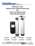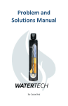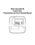
1
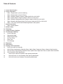
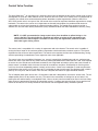
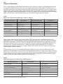
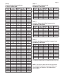
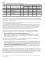
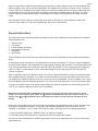
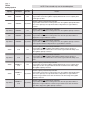
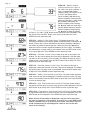
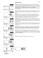
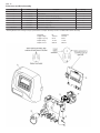
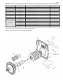
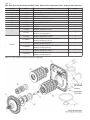
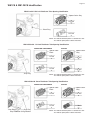
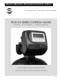
SAFE
WATER
TECHNOLOGIES, INC.
O P E R A T I O N
&
I N S T R U C T I O N
M A N U A L
TECH-CS SERIES CONTROL VALVES
FILTERS ,
SOFTENERS ,
CONDITIONERS
1 INCH TECH SERIES CONTROL VALVE MODEL: WS1CS
1.25 INCH TECH SERIES CONTROL VALVE MODEL: WS1.25CS
MAY 2012
Table of Contents
3.
4.
4.
4.
5.
5.
5.
5.
6.
7.
8.
9.
10.
11.
12.
12.
12.
12.
13.
13.
13.
13.
15.
16.
16.
17.
18.
19.
19.
19.
19.
Control Valve Function
Cycles of Operation
Table 1: Regeneration Cycles for Softening
Table 2: Regeneration Cycles for Filtering
Table 3: Downflow Softener Program Codes for WS1CS or WS1.25CS
Table 4: Upflow Softener Program Codes for WS1CS or WS1.25CS
Table 5: Downflow Regenerating Filter Program Codes for WS1CS or WS1.25CS
Table 6: Downflow Non-Regenerating Filter Program Codes for WS1CS or WS1.25CS
Table 7: Time Clock and Demand Initiated Regeneration (DIR) Options
General Instructions
Table 8: Setting Options
Softener Setup
Filter Setup
Installer Displays & Settings
User Displays & Settings
General Operation
Regeneration Mode
Manual Regeneration
Set Time of Day
Power Loss
Error Message
Diagnostics
Valve History
Drawings and Part Numbers
Front Cover and Drive Assembly
WS1CS Drive Cap Assembly, Downflow Piston, Upflow Piston, Regenerant Piston, & Spacer Stack Assembly
WS1.25CS Drive Cap Assembly, Downflow Piston, Upflow Piston, Regenerant Piston, & Spacer Stack Assemblies
WS1CS and WS1.25CS Identification
WS1CS with 1.050 inch Distributor Tube Opening Identification
WS1.25CS with 1.32 inch Distributor Tube Opening Identification
WS1.25CS with 32mm Distributor Tube Opening Identification
Control Valve Function
Page 3
This glass-filled Noryl 1 (or equivalent) fully automatic control valve is designed as the primary control center to direct
and regulate all cycles of a water softener or filter. When the WS1CS or WS1.25CS control valve is manufactured as
a softener, the control valve can be ordered to perform downflow or upflow regeneration. When the WS1CS or
WS1.25CS control valve is set up as a filter, the control valve can be set to perform downflow regeneration or simply
backwash. The control valve can be set to regenerate on demand (consumption of a predetermined amount of
water) and/or as a time clock (passage of a particular number of days). The control valve can be set so that a
softener can meet the Water Quality Association (WQA) Standard S100 or NSF/ANSI Standard 44 efficiency rating.
* NOTE: It is NOT recommended to change control valves from downflow to upflow brining or vice
versa in the field. The valve bodies for downflow and upflow are unique to the regeneration type
and should not be interchanged. A mismatch of valve body and regeneration piston will result in
hard water bypass during service.
The control valve is compatible with a variety of regenerants and resin cleaners. The control valve is capable of
routing the flow of water in the necessary paths to regenerate or backwash water treatment systems. The injector
regulates the flow of brine or other regenerants. The control valve regulates the flow rates for backwashing, rinsing,
and the replenishing of treated water into a regenerant tank, when applicable.
The control valve uses no traditional fasteners (e.g. screws); instead clips, threaded caps and nuts, and snap type
latches are used. Caps and nuts only need to be firmly hand tightened because radial seals are used. Tools required
to service the valve include one small blade screwdriver, one large blade screwdriver, pliers, and a pair of hands. A
plastic wrench is available which eliminates the need for screwdrivers and pliers. Disassembly for servicing takes
much less time than comparable products currently on the market. Control valve installation is made easy because
the distributor tube can be cut 0.5 inch above to 0.5 inch below the top of tank thread. The distributor tube is held in
place by an o-ring seal, and the control valve also has a bayonet lock feature for upper distributor baskets.
The AC adapter power pack comes with a 15 foot power cord and is designed for use with the control valve. The AC
adapter power pack is for dry location use only. The control valve remembers all settings for up to 8 hours if the
power goes out and the battery is not depleted. After 8 hours, the only item that needs to be reset is the time of day;
other values are permanently stored in the nonvolatile memory. If a power loss lasts less than 8 hours and the time
flashes on and off, the time of day should be reset and the non-rechargeable battery should be replaced.
1. Noryl is a trademark of General Electric.
Page 4
Cycles of Operation
Table 1 (below) shows the order of the cycles when the valve is set up as a softener. It allows the option of having
the regenerant refill after the rinse cycle or have the regenerant prefill before regeneration. If chosen to have the
regenerant prefill before regeneration, the prefill starts two hours before the regeneration time set. During the 2-hour
period in which the brine is being made, treated (softened) water is still available. For example: regeneration time =
2:00am, prefill option selected, downflow softener. Fill occurs at 12:00am, start of backwash cycle occurs at 2:00am.
Tables 3 and 4 (Page 5) show the length of the cycles when different program codes are selected.
Table 1
Regeneration Cycles for Softening (See * NOTE on page 3)
WS1CS & WS1.25CS — Downflow
Regenerant Refill After Rinse
WS1CS & WS1.25CS — Downflow
Regenerant Prefill
WS1CS & WS1.25CS — Upflow
Regenerant Refill After Rinse
WS1CS & WS1.25CS — Upflow
Regenerant Prefill
1st Cycle: Backwash
1st Cycle: Fill
1st Cycle: Regenerate
1st Cycle: Fill
3rd Cycle: Second Backwash *
3rd Cycle: Backwash
3rd Cycle: Rinse
3rd Cycle: Regenerate
2nd Cycle: Regenerate
4th Cycle: Rinse
5th Cycle: Fill / Dissolve
6th Cycle: Service
* Second Backwash is optional.
2nd Cycle: Service
4th Cycle: Regenerate
5th Cycle: Second Backwash *
6th Cycle: Rinse
2nd Cycle: Backwash
4th Cycle: Fill / Dissolve
5th Cycle: Service
7th Cycle: Service
2nd Cycle: Service
4th Cycle: Backwash
5th Cycle: Rinse
6th Cycle: Service
Table 2 (below) shows the order of the cycles when the valve is set up as a filter. If the control valve is set to
regenerate for a filter, it allows the option of having the regenerant refill after the rinse cycle or have the regenerant
prefill before regeneration. If chosen to have the regenerant prefill before regeneration, the prefill starts two hours
before the regeneration time set. During the 2-hour period in which the regenerant is being made, treated water is
still available. For example: regeneration time = 2:00am, prefill option selected, downflow filter. Fill occurs at
12:00am, start of backwash cycle occurs at 2:00am. Tables 5 and 6 (Page 5) show the length of the cycles when
different program codes are selected.
When the control valve is used as a non-regenerating filter (backwash only), it allows the option to specify one
backwash or two backwashes. If two backwashes are specified, two rinses occur. Tables 5 and 6 (Page 5) show the
length of the cycles when the valve is set up as a filter. When used as a non-regenerating filter, the downflow piston
must be installed, the regenerant piston removed, injector plugs must be installed in both the DN and UP injector
locations, and the refill elbow must be replaced with a refill port plug.
Table 2
Regeneration Cycles for Filtering (See * NOTE on page 3)
WS1CS & WS1.25CS — Downflow
Regenerant Refill After Rinse
WS1CS & WS1.25CS — Downflow
Regenerant Prefill
WS1CS & WS1.25CS — No Regenerant
1st Cycle: Backwash
1st Cycle: Fill
1st Cycle: Backwash
3rd Cycle: Second Backwash *
3rd Cycle: Backwash
3rd Cycle: Second Backwash *
2nd Cycle: Regenerate
4th Cycle: Rinse
5th Cycle: Fill
6th Cycle: Service
2nd Cycle: Service
4th Cycle: Regenerate
5th Cycle: Second Backwash *
6th Cycle: Rinse
7th Cycle: Service
* Second Backwash is optional
** Second rinse only occurs if “Second Backwash” option is selected.
2nd Cycle: Rinse
4th Cycle: Second Rinse **
5th Cycle: Service
Table 3
Downflow Softener Program Codes
for WS1CS or WS1.25CS
Table 4
Upflow Softener Program Codes
for WS1CS or WS1.25CS
Page 5
Program
Code
1st
Backwash
Brine/Slow
Rinse
2nd
Backwash
Fast Rinse
Program
Code
1st
Backwash
Brine/Slow
Rinse
2nd
Backwash
Fast Rinse
P2
3
45
3
3
P61
N/A
45
8
6
P1
P3
P4
P5
P6
P7
P8
P9
P10
P11
P12
P13
P14
P15
P16
P17
P18
P19
P20
P21
3
4
4
5
5
6
6
6
7
7
7
8
8
8
8
8
8
9
9
9
P22
10
P24
10
P23
P25
P26
P27
P28
P29
P30
P31
P32
P33
P34
P35
P36
P37
P38
P39
P40
P41
P42
P43
P44
P45
P50
P51
P52
10
10
10
12
12
12
12
12
12
12
14
14
14
14
14
14
14
16
16
16
16
16
6
8
8
40
45
60
60
60
45
60
60
50
60
65
45
60
60
65
65
75
50
60
65
45
60
65
65
75
45
60
60
65
65
3
4
4
4
5
4
5
6
5
6
7
5
6
8
8
8
8
5
5
8
4
5
8
6
7
4
6
8
6
8
65
12
45
5
75
60
60
65
65
6
6
8
7
8
65
12
60
7
75
65
65
8
8
8
65
12
45
3
75
60
75
9
8
10
3
P60
3
P62
4
P64
3
4
3
4
5
4
6
7
4
P63
P65
N/A
N/A
N/A
N/A
N/A
45
6
60
10
75
10
60
75
4
6
12
8
6
12
8
Table 5
Downflow Regenerating Filter Program Codes
for WS1CS or WS1.25CS
6
Program
Code
1st
Backwash
Brine/Slow
Rinse
2nd
Backwash
Fast Rinse
6
P71
12
10
N/A
12
P73
10
50
N/A
P75
12
8
7
5
5
4
5
4
4
8
5
5
4
P70
P72
P74
6
20
4
50
12
60
75
6
N/A
N/A
N/A
6
4
6
10
10
Table 6
Downflow Non-Regenerating Filter Program Codes
for WS1CS or WS1.25CS
4
Program
Code
1st
Backwash
1st
Fast Rinse
2nd
Backwash
2nd
Fast Rinse
6
P81
12
6
N/A
N/A
P83
14
10
18
10
8
8
8
6
4
5
8
6
8
8
7
5
6
8
8
7
3
4
6
P80
P82
P84
P85
8
14
16
P86
20
P91
12
P90
8
8
8
10
10
6
6
N/A
N/A
N/A
N/A
N/A
N/A
10
12
N/A
N/A
N/A
N/A
N/A
N/A
8
10
NOTE: For non-regenerant filters: 1) The regenerant piston is removed;
2) Injector plugs are installed in both the UP and DN holes under the injector cap.
NOTE: The program codes listed on this page should
be used only as a guideline. Any program code listed
can be applied to a softener or filter application for
WS1CS valves.
Page 6
Table 7
Time Clock and Demand Initiated Regeneration (DIR) Options
Time
Clock
DIR
—
Yes
—
Yes
Yes
Yes
Yes
Yes
Yes
—
Reserve Capacity
Automatically calculated
If desired enter a value less than
estimated capacity
Automatically calculated
If desired enter a value less than
estimated capacity
None
Softener
Filter
Settings *
Regenerant
Backwash
Only
Day Override
Gallons
Capacity
Yes
Yes
Yes
Off
Any Number
Yes
—
—
Any Number
Auto
Yes
Yes
Yes
Any Number
Any Number
Yes
Yes
Yes
Any Number
Off
Yes
* Day Override and Gallons Capacity can not both be set to “oFF” at the same time.
—
—
Off
Auto
The control valve with a water meter can be set for Demand Initiated Regeneration (DIR) only, Time Clock operation
only, or DIR and Time Clock whichever comes first, depending upon what settings are selected for Day Override and
Gallons Capacity. 2 (See Table 7 above.)
If a control valve does not contain a meter, the valve can only act as a Time Clock, and Day Override should be set
to any number and Gallons Capacity should be set to “oFF”.
For DIR Softeners, there are two options for setting the Gallons Capacity (Step 7-SS, Page 9 or Step 6-FS, Page 10).
The Gallons Capacity is automatically calculated if set to “AUTO”. Reserve Capacity is automatically estimated
based on water usage if “AUTO” is used. The other option is to set the Gallons Capacity to a specific number. If a
specific number is set, Reserve Capacity is 0 (zero), unless the value is manually set (i.e. the manufacturer
intentionally sets the Gallons Capacity number below the calculated capacity of the system).
The control valve can also be set to regenerate immediately or at the next regeneration time by changing the
Regeneration Time Option (Step 8-SS, Page 9 or Step 7-FS, Page 10). There are three choices for settings:
1. “NORMAL” means regeneration will occur at the preset regeneration time.
2. “on 0” means regeneration will occur when the Gallons Capacity reaches 0 (zero).
3. “NORMAL” and “on 0” (NORMAL + on 0) means the regeneration will occur at the preset regeneration time
unless the Gallons Capacity reaches 0 (zero). If the Gallons Capacity reaches 0 (zero), the regeneration will
begin 10 minutes after no water usage.
The user can initiate manual regeneration. The user has the option to request the manual regeneration at the
delayed regeneration time or to have the regeneration occur immediately:
1. Pressing and releasing the REGEN button will flash “REGEN TODAY” on the display and the regeneration will
occur at the delayed regeneration time. The user can cancel the request by pressing and releasing the REGEN
button. This method of manually initiating regeneration is not allowed when the system is set to “on 0” (i.e. to
immediately regenerate when the Gallons Capacity reaches zero).
2. Pressing and holding the REGEN button for approximately 3 seconds will immediately start the regeneration.
The user cannot cancel this request, except by resetting the control by pressing NEXT and REGEN buttons
simultaneously for 3 seconds.
A unique feature of this control valve is the ability to display actual water usage for the last 63 days. The values are
initially stored as “----”. This means the value is unknown. As days pass, values are stored as “0” (for “no flow”) or the
actual number of gallons. The counting of the gallons starts at the regeneration time. If no regeneration time can be
set (i.e. when the valve is set for immediate regeneration) the counting of gallons starts at 12am. Day 1 is yesterday,
Day 2 the day before yesterday, etc. As new values are added the oldest history disappears.
2. See Installer Displays & Settings Step 3-IS (Page 11), Softener Setup Step 7-SS (Page 9), and Filter Setup Step 6-FS (Page 10) for explanations of Day Override
and Gallons Capacity.
Page 7
Another unique feature is that the valve automatically calculates a reserve capacity when set up as a softener with
Gallons Capacity set to “AUTO” and the Regeneration Time Option set to “Normal” or “Normal + on 0”. The actual
Reserve Capacity is compared to the Gallons Capacity remaining immediately prior to the preset regeneration time.
A regeneration will occur if the actual Reserve Capacity is less than the Gallons Capacity remaining. The actual
Reserve Capacity is calculated by using the estimated Reserve Capacity and adjusting it up or down for actual
usage.
The estimated Reserve Capacity for a given day of the week is the maximum value stored for the last three
non-trivial water usages (i.e. more than 20 gallons per day) in seven day intervals.
General Instructions
The control valve offers multiple procedures that allow the valve to be modified to suit the needs of the installation.
These procedures are:
1.
2.
3.
4.
5.
6.
Softener Setup
Filter Setup
Installer Displays & Settings
User Displays & Settings
Diagnostics
Valve History
These procedures can be accessed in any order. Details on each of the procedures are provided on the following
pages.
At the discretion of the manufacturer, the field technician can access all settings. To “lock out” access to Diagnostic
and Valve History displays, and modifications to settings except Hardness, Day Override, Time of Regeneration, and
Time of Day by anyone but the manufacturer, press q, NEXT, p, and SET CLOCK in sequence after settings are
made. To “unlock,” so other displays can be viewed and changes can be made, press q, NEXT, p, and SET
CLOCK in sequence.
When in operation, normal user displays such as Time of Day, Capacity Remaining, or Days Remaining are shown.
When stepping through a procedure, if no buttons are pressed within five minutes, the display returns to a normal
user display. Any changes made prior to the five minute time-out are incorporated. The one exception is the Current
Flow Rate display under the Diagnostic procedure. The Current Flow Rate display has a 30 minute time-out feature.
To quickly exit Softener Setup, Filter Setup, Installer Displays & Settings, Diagnostics, or Valve History, press SET
CLOCK. Any changes made prior to the exit are incorporated.
When desired all information in Diagnostics may be reset to 0 (zero) when the valve is moved to a new
location. To reset to 0 (zero), press NEXT and q buttons simultaneously to go to the Service screen, and
release. Press p and q simultaneously to reset Diagnostic values to 0 (zero). Screen will return to User
Display.
Sometimes it is desirable to have the valve initiate and complete two regenerations within 24 hours and then return
to the preset regeneration procedure. It is possible to do a double regeneration if the control valve is set to
“NORMAL” or “NORMAL + on 0” in Step 8-SS (Page 9) or Step 7-FS (Page 10). To do a double regeneration:
1. Press the REGEN button once. “REGEN TODAY” will flash on the display.
2. Press and hold the REGEN button for 3 seconds until the valve regeneration initiates.
Once the valve has completed the immediate regeneration, the valve will regenerate one more time at the preset
regeneration time.
Page 8
Table 8
Setting Options
NOTE: Filters should only use the shaded options.
Gallons
Capacity
Regeneration
Time Option
Day
Override
AUTO
NORMAL
oFF
AUTO
NORMAL
Any number
Any number
NORMAL
oFF
oFF
NORMAL
Any number
Any number
NORMAL
Any number
AUTO
on 0
Any number
on 0
AUTO
NORMAL +
on 0
AUTO
NORMAL +
on 0
Any number
NORMAL +
on 0
oFF
oFF
oFF
Any number
Any number
Result *
Reserve capacity automatically estimated.
Regeneration occurs when gallons capacity falls below the reserve capacity at the
next Regen Set Time.
Reserve capacity automatically estimated.
Regeneration occurs at the next Regen Set Time when gallons capacity falls below
the reserve capacity or the specified number of days between regenerations is
reached.
Reserve capacity not automatically estimated.
Regeneration occurs at the next Regen Set Time when gallons capacity reaches 0.
Reserve capacity not automatically estimated.
Regeneration occurs at the next Regen Set Time when the specified number of
days between regenerations is reached.
Reserve capacity not automatically estimated.
Regeneration occurs at the next Regen Set Time when gallons capacity reaches 0
or the specified number of days between regenerations is reached.
Reserve capacity not automatically estimated.
Regeneration occurs immediately when gallons capacity reaches 0. Time of
regeneration will not be allowed to be set because regeneration will always occur
when gallons capacity reaches 0.
Reserve capacity not automatically estimated.
Regeneration occurs immediately when gallons capacity reaches 0. Time of
regeneration will not be allowed to be set because regeneration will always occur
on 0.
Reserve capacity automatically estimated.
Regeneration occurs when gallons capacity falls below the reserve capacity at the
next Regen Set Time or regeneration occurs after 10 minutes of no water usage
when gallon capacity reaches 0.
Reserve capacity automatically estimated.
Regeneration occurs at the next Regen Set Time when gallons capacity falls below
the reserve capacity or the specified number of days between regenerations is
reached or regeneration occurs after 10 minutes of no water usage when gallon
capacity reaches 0.
Reserve capacity not automatically estimated.
Regeneration occurs at the next Regen Set Time when the specified number of
days between regenerations is reached or regeneration occurs after 10 minutes
of no water usage when gallon capacity reaches 0.
* Reserve Capacity estimate is based on history of water usage.
Softener Setup
Page 9
This is a quick reference setup procedure.
STEP 1-SS – Press NEXT and q buttons simultaneously for 3 seconds. If
screen in Step 2-SS does not appear in 5 seconds the lock on the valve is
activated. To unlock press q, NEXT, p, and SET CLOCK in sequence, then
press NEXT and q simultaneously for 3 seconds.
STEP 2-SS – Mode: Choose “SOFTENING” using q or p buttons. Press NEXT
to go to Step 3-SS. Press REGEN to exit Softener Setup.
STEP 3-SS – Refill: Set Refill Option using q or p buttons:
— “PoST” to refill the brine tank after the final rinse; or
— “PrE” to refill the brine tank two hours before the regeneration time set.
Press NEXT to go to Step 4-SS. Press REGEN to return to previous step.
STEP 4-SS – Program Code: Enter the desired program code from Table 3 or
Table 4 (Page 5). Prior to selecting a Program Code, verify the correct valve
body, main piston, regenerant piston, and stack are being used, and that the
injector or injector plug(s) are in the correct locations. See Compliance Table in
WS1 and WS1.25 Drawings and Service Manual. Press NEXT to go to Step 5-SS.
Press REGEN to return to previous step.
STEP 5-SS – Hardness: Enter the ion exchange capacity in grains of hardness
as calcium carbonate for the system based on test data using q or p buttons.
Press NEXT to go to Step 6-SS. Press REGEN to return to previous step.
STEP 6-SS – Salt: Enter the pounds of salt per regeneration using q or p
buttons. Press NEXT to go to Step 7-SS. Press REGEN to return to previous step.
STEP 7-SS – Gallons Capacity: Set Gallons Capacity using q or p buttons:
— “AUTO” (reserve capacity automatically estimated and gallons capacity
automatically calculated from grains capacity and water hardness);
— “oFF” (regeneration based on day override); or
— number of gallons (20 to 50,000).
See Table 8, Setting Options (Page 8) for more detail. Press NEXT to go to Step
8-SS. Press REGEN to return to previous step.
STEP 8-SS – Regen Time: Set Regeneration Time Option using q or p buttons:
— “NORMAL” means regeneration will occur at the preset time;
— “on 0” means regeneration will occur immediately when the gallons capacity
reaches 0 (zero); or
— “NORMAL + on 0” means regeneration will occur at one of the following:
the preset time when the gallons capacity falls below the reserve or the
specified number of
— days between regenerations is reached whichever comes first; or
— after 10 minutes of no water usage when the gallon capacity reaches
0 (zero).
See Table 8, Setting Options (Page 8) for more detail. Press NEXT to exit
Softener Setup. Press REGEN to return to previous step.
Page 10
Filter Setup
This is a quick reference setup procedure.
STEP 1-FS – Press NEXT and q simultaneously for 3 seconds. If screen in
Step 2-FS does not appear in 5 seconds the lock on the valve is activated. To
unlock press q, NEXT, p, and SET CLOCK in sequence, then press NEXT and
q simultaneously for 3 seconds.
STEP 2-FS – Mode: Choose “FILTERING” using q or p buttons. Press NEXT
to go to Step 3-FS. Press REGEN to exit Filter Setup.
STEP 3-FS – Refill: Set Refill Option using q or p buttons:
— “PoST” to refill the brine tank after the final rinse; or
— “PrE” to refill the brine tank two hours before the regeneration time set.
Press NEXT to go to Step 4-FS. Press REGEN to return to previous step.
STEP 4-FS – Program Code: Enter the desired program code from Table 2,
Table 5, or Table 6 (Page 5). Prior to selecting a Program Code, verify the
correct valve body, main piston, regenerant piston, and stack are being used,
and that the injector or injector plug(s) are in the correct locations. See
Compliance Table in WS1 and WS1.25 Drawings and Service Manual. Press
NEXT to go to Step 5-FS. Press REGEN to return to previous step.
STEP 5-FS – Refill Volume: Enter “oFF” if regenerant is not used (i.e. backwash
only) or enter the refill volume (in gallons) using q or p buttons. Press NEXT to
go to Step 6-FS. Press REGEN to return to previous step.
STEP 6-FS – Gallons Capacity: Set Gallons Capacity using q or p buttons:
— “oFF” (regeneration based on day override); or
— number of gallons (20 to 50,000).
See Table 8, Setting Options (Page 8) for more detail. Press NEXT to go to
Step 7-FS. Press REGEN to return to previous step.
STEP 7-FS – Regen Time: Set Regeneration Time Option using q or p buttons:
— “NORMAL” means regeneration will occur at the preset time;
— “on 0” means regeneration will occur immediately when the gallons capacity
reaches 0 (zero); or
— “NORMAL + on 0” means regeneration will occur at one of the following:
— the preset time when the specified number of days between
regenerations is reached; or
— after 10 minutes of no water usage when the gallon capacity reaches
0 (zero).
See Table 8, Setting Options (Page 8) for more detail. Press NEXT to exit Filter
Setup. Press REGEN to return to previous step.
Installer Displays & Settings
Page 11
STEP 1-IS – Press NEXT and p simultaneously for 3 seconds.
STEP 2-IS – Hardness: Set the amount of hardness in grains of hardness as
calcium carbonate per gallon using the q or p buttons. The default is 20 with
value ranges from 1 to 150 in 1 grain increments.
Note: The grains per gallon can be increased if soluble iron needs to be
reduced. This display will show “–nA–” if “FILTERING” is selected in Step 2-FS
(Page 10) or if “AUTO” is not selected in Step 7-SS (Page 9).
Press NEXT to go to Step 3-IS. Press REGEN to exit Installer Displays &
Settings.
STEP 3-IS – Day Override: When Gallons Capacity is set to “oFF”, sets the
number of days between regenerations. When gallon capacity is set to “AUTO”
or to a number, sets the maximum number of days between regenerations. If
value set to “oFF” regeneration initiation is based solely on gallons used. If value
is set as a number (allowable range from 1 to 28) a regeneration initiation will be
called for on that day even if sufficient number of gallons were not used to call
for a regeneration. Set Day Override using q or p buttons:
— number of days between regeneration (1 to 28); or
— “oFF”.
See Table 8, Setting Options (Page 8) for more detail on setup. Press NEXT to
go to Step 4-IS. Press REGEN to return to previous step.
STEP 4-IS – Next Regeneration Time (Hour): Set the hour of day for regeneration
using q or p buttons. AM/PM toggles after 12. The default time is 2:00am This
display will show “REGEN on 0 GAL” if “on 0” is selected in Step 8-SS (Page 9) or
Step 7-FS (Page 10). Press NEXT to go to Step 5-IS. Press REGEN to return to
previous step.
STEP 5-IS – Next Regeneration Time (Minutes): Set the minutes of day for
regeneration using q or p buttons. This display will not be shown if “on 0” is
selected in Step 8-SS (Page 9) or Step 7-FS (Page 10). Press NEXT to exit
Installer Displays & Settings. Press REGEN to return to previous step.
To initiate a manual regeneration immediately, press and hold the REGEN
button for three seconds. The system will begin to regenerate immediately. The
control valve may be stepped through the various regeneration cycles by
pressing the REGEN button.
Page 12
User Displays & Settings
General Operation
When the system is operating one of two
displays will be shown. Pressing NEXT will
alternate between the displays. One of the
displays is always the current Time of Day.
The second display is one of the following:
Days Remaining or Capacity Remaining. Days
Remaining is the number of days left before
the system goes through a regeneration cycle.
Capacity Remaining is the number of gallons
that will be treated before the system goes
through a regeneration cycle. The user can
scroll between the displays as desired.
If the system has called for a regeneration that will occur at the preset time of regeneration, the words “REGEN
TODAY” will appear on the display.
When water is being treated (i.e. water is flowing through the system) the word “SOFTENING” or “FILTERING”
flashes on the display if a water meter is installed.
Regeneration Mode
Typically a system is set to regenerate at a time of low water usage. An
example of a time with low water usage is when a household is asleep. If
there is a demand for water when the system is regenerating, untreated
water will be used.
When the system begins to regenerate, the display will change to include information about the step of the
regeneration process and the time remaining for that step to be completed. The system runs through the steps
automatically and will reset itself to provide treated water when the regeneration has been completed.
Manual Regeneration
Sometimes there is a need to regenerate the system
sooner than when the system calls for it, usually
referred to as manual regeneration. There may be a
period of heavy water usage because of guests or a
heavy laundry day.
To initiate a manual regeneration at the preset delayed
regeneration time, when the regeneration time option is set to “NORMAL” or “NORMAL + on 0”, press and release
REGEN. The words “REGEN TODAY” will flash on the display to indicate that the system will regenerate at the
preset delayed regeneration time. If you pressed the REGEN button in error, pressing the button again will cancel the
request.
Note: If the regeneration time option is set to “on 0” there is no set delayed regeneration time so “REGEN TODAY”
will not activate if REGEN button is pressed.
To initiate a manual regeneration immediately, press and hold the REGEN button for three seconds. The system will
begin to regenerate immediately. The request cannot be cancelled.
Note: For softeners, if brine tank does not contain salt, fill with salt and wait at least two hours before regenerating.
Set Time of Day
Page 13
The user can also set the time of day. Time of day should only need to be set
after power outages lasting more than 8 hours, if the battery has been depleted
and a power outage occurs, or when daylight saving time begins or ends. If a
power outage lasting more than 8 hours occurs, the time of day will flash on and
off which indicates the time of day should be reset. If a power outage lasts less
than 8 hours and the time of day flashes on and off, the time of day should be
reset and the battery replaced.
STEP 1-TD – Press SET CLOCK.
STEP 2-TD – Current Time (Hour): Set the hour of the day using q or p
buttons. AM/PM toggles after 12. Press NEXT to go to Step 3-TD.
STEP 3-TD – Current Time (Minutes): Set the minutes of the day using q or p
buttons. Press NEXT to exit Set Clock. Press REGEN to return to previous step.
Power Loss
If the power goes out, the system will keep time for up to 8 hours or until the
battery is depleted. If a power outage of more than 8 hours occurs, the time of
day will flash on and off which indicates the time of day should be reset. The
system will remember the rest. If a power outage lasts less than 8 hours and the
time of day flashes on and off, the non-rechargeable battery should be replaced.
Error Message
If the word “Error” and a number are alternately flashing on the display contact
the OEM for help. This indicates that the valve was not able to function properly.
Diagnostics
STEP 1-DI – Press q and p simultaneously for three seconds. If screen in Step
2-DI does not appear in 5 seconds the lock on the valve is activated. To unlock
press q, NEXT, p, and SET CLOCK in sequence, then press q and p
simultaneously for 3 seconds.
STEP 2-DI – Days, Since Last Regeneration: This display shows the days since
the last regeneration occurred. Press the NEXT button to go to Step 3-DI. Press
REGEN to exit Diagnostics.
STEP 3-DI – Gallons, Since Last Regeneration: This display shows the number
of gallons that have been treated since the last regeneration. This display will
equal 0 (zero) if a water meter is not installed. Press the NEXT button to go to
Step 4-DI. Press REGEN to return to previous step.
Diagnostics continued on next page.
Page 14
STEP 4-DI – Gallons, Reserve
Capacity Used for Last 7 Days: If
the valve is set up as a softener, a
meter is installed and Gallons
Capacity (Step 7-SS, Page 9) is set
to “Auto”, this display shows
Day 0 (for today) and flashes the
Reserve Capacity. Pressing the p
button will show Day 1 (which would
be yesterday) and flashes the
Reserve Capacity used. Pressing
the p button again will show Day 2
(the day before yesterday) and the
Reserve Capacity. Keep pressing
the p button to show the gallons
for Days 3, 4, 5 and 6. The q button can be pressed to move backwards in the
Day series. Press the NEXT button at any time to go to Step 5-DI. Press
REGEN to return to previous step.
STEP 5-DI – Gallons, 63 Day Usage History: This display shows Day 1 (for
yesterday) and flashes the number of gallons treated yesterday. Pressing the p
button will show Day 2 (which would be the day before yesterday) and flashes
the number of gallons treated on that day. Continue to press the p button to
show the maximum number of gallons treated for the last 63 days. This display
will show dashes if a water meter is not installed. Press the NEXT button at any
time to go to Step 6-DI. Press REGEN to return to previous step.
STEP 6-DI – Flow Rate, Current: Turn the water on at one or more taps in the
building. The flow rate in gallons per minute will be displayed. If the flow stops,
the value will fall to 0 (zero) in a few seconds. This display will equal 0 (zero) if
a water meter is not installed. Press the NEXT button to go to Step 7-DI. Press
REGEN to return to previous step.
STEP 7-DI – Flow Rate, Maximum Last 7 Days: The maximum flow rate in
gallons per minute that occurred in the last 7 days will be displayed. This display
will equal 0 (zero) if a water meter is not installed. Press the NEXT button to go
to Step 8-DI. Press REGEN to return to previous step.
STEP 8-DI – Gallons, Total Used Since Last Reset: The total number of gallons
used since last reset will be displayed. This display will equal 0 (zero) if a water
meter is not installed. Press the NEXT button to go to Step 9-DI. Press REGEN
to return to previous step.
STEP 9-DI – Days, Total Number Since Last Reset: The total number of days
the control valve has been in service since last reset will be displayed. Press the
NEXT button to go to Step 10-DI. Press REGEN to return to previous step.
STEP 10-DI – Regenerations, Total Number Since Last Reset: The total number
of regenerations that have occurred since last reset will be displayed. Press the
NEXT button to exit Diagnostics. Press REGEN to return to previous step.
When desired, all information in Diagnostics may be reset to zero when
the valve is installed in a new location. To reset to zero, press NEXT and q
buttons simultaneously to go to the Service screen, and release. Press q
and p simultaneously to reset Diagnostic values to zero. Screen will
return to User Display.
Valve History
Page 15
STEP 1-VH – Press q and p simultaneously for three seconds and release.
Then press q and p simultaneously again and release. If screen in Step 2-VH
does not appear in 5 seconds the lock on the valve is activated. To unlock press
q, NEXT, p, and SET CLOCK in sequence, then press q and p
simultaneously for 3 seconds and release. Then press q and p simultaneously
again and release.
STEP 2-VH – Software Version: This display shows the software version of the
valve. Press the NEXT button to go to Step 3-VH. Press REGEN to exit Valve
History.
STEP 3-VH – Flow Rate, Maximum Since Startup: This display shows the
maximum flow rate in gallons per minute that has occurred since startup. This
display will equal 0 (zero) if a water meter is not installed. Press the NEXT
button to go to Step 4-VH. Press REGEN to return to previous step.
STEP 4-VH – Gallons, Total Used Since Startup: This display shows the total
gallons treated since startup. This display will equal 0 (zero) if a water meter is
not installed. Press the NEXT button to go to Step 5-VH. Press REGEN to return
to previous step.
STEP 5-VH – Days, Total Since Startup: This display shows the total days since
startup. Press the NEXT button to go to Step 6-VH. Press REGEN to return to
previous step.
STEP 6-VH – Regenerations, Total Number Since Startup: This display shows
the total number of regenerations that have occurred since startup. Press the
NEXT button to go to Step 7-VH. Press REGEN to return to previous step.
STEP 7-VH – Error Log: This display shows a history of the last 10 errors
generated by the control during operation. Press the q or p buttons to review
each error recorded. Press the NEXT button to exit Valve History. Press REGEN
to return to previous step.
NOTE: Values in Steps 3-VH through 7-VH cannot be reset.
Page 16
Front Cover and Drive Assembly
Drawing No.
1
2
3
Part No.
WS1CS Front Cover Assembly
LC-V3106-01
WS1CS Drive Bracket and Spring Clip
LC-V3107-01
4
LC-V3108CS-01
6
LC-V3109
Not Shown
LC-V3186-01
5
*
Description
LC-V3175-01
LC-V3110
LC-V3002
Quantity
1
WS1CS Motor
1
WS1CS/WS1.25CS PC Board with Battery
1
1
WS1CS Drive Reducing Gear 12 x 36
3
WS1CS Drive Assembly
*
WS1CS Drive Gear Cover
1
WS1CS AC Adapter 120V-12V
* Drawing Number Parts 2 through 6 may be purchased as a complete assembly: Part No. LC-V3002, WS1CS Drive Assembly.
AC Adapter
Supply Voltage
Supply Frequency
Output Voltage
Output Current
US
120 VAC
60 Hz
12 VAC
500 mA
International
230 VAC
50 Hz
12 VAC
500 mA
1
Page 17
WS1CS Drive Cap Assembly, Downflow Piston, Upflow Piston, Regenerant Piston, & Spacer Stack Assembly
Drawing No.
1
2
3
4a
Part No.
LC-V3005
LC-V3004
LC-V3178
LC-V3011 *
4b
LC-V3011-01 *
6
LC-V3135
5
7
8
Not Shown
LC-V3174
LC-V3180
LC-V3105
LC-V3001
LC-V3001-02
LC-V3001UP
LC-V3001-02UP
LC-V3013
Description
WS1CS Spacer Stack Assembly
Drive Cap Assembly
WS1CS Drive Backplate
WS1CS Piston Downflow Assembly
WS1CS Piston Upflow Assembly
WS1CS Regenerant Piston
O-ring 228
O-ring 337
O-ring 215 (Distributor Tube)
WS1CS Body Downflow Assembly
WS1CS Mixing Valve Body Assembly
WS1CS Body Upflow Assembly
WS1CS Mixing Valve Body Upflow Assembly
WS1CS Mixing Valve Assembly
* P/N: LC-V3011 is labeled with “DN” and P/N: LC-V3011-01 is labeled with “UP.”
NOTE: The regenerant piston is not used in backwash only applications.
Quantity
1
1
1
1
1
1
1
1
1
1
1
1
1
1
Page 18
WS1.25CS Drive Cap Assembly, Downflow Piston, Upflow Piston, Regenerant Piston, & Spacer Stack Assembly
Drawing No.
Part No.
Description
1a
LC-V3430
WS1.25CS Spacer Stack Downflow Assembly
2
LC-V3004
Drive Cap Assembly
LC-V3407
WS1.25CS Piston Downflow Assembly
1b
3
4a
LC-V3005
LC-V3178
4b
LC-V3011-01
6
LC-V3135
5
7
8
LC-V3174
LC-V3180
LC-V3358
LC-V3357
LC-V3020
LC-V3020-01
Not Shown
LC-V3020-02
WS1.25CS Spacer Stack Upflow Assembly
WS1.25CS Drive Backplate
WS1.25CS Piston Upflow Assembly
WS1.25CS Regenerant Piston
O-ring 228
O-ring 337
O-ring 219
(Distributor Tube Opening 1.32 inch)
O-ring 218
(Distributor Tube Opening 32mm)
WS1.25CS Body Downflow Assembly
(Distributor Tube Opening 1.32 inch)
WS1.25CS Mixing Valve Body Downflow Assembly
(Distributor Tube Opening 1.32 inch)
WS1.25CS Body Downflow Assembly
(Distributor Tube Opening 32mm)
WS1.25CS Mixing Valve Body Downflow Assembly
NOTE: The regenerant piston is LC-V3020-03
not used in backwash(Distributor
only applications.
Tube Opening 32mm)
LC-V3020UP
LC-V3020-02UP
WS1.25CS Body Upflow Assembly
(Distributor Tube Opening 1.32 inch)
WS1.25CS Body Upflow Assembly
(Distributor Tube Opening 32mm)
NOTE: The regenerant piston is not used in backwash only applications.
Quantity
1
1
1
1
1
1
1
1
1
1
1
1
1
1
1
1
1
Page 19
WS1CS & WS1.25CS Identification
WS1CS with 1.050 inch Distributor Tube Opening Identification
Spacer Color: Gray
1.25 inch
Black Plug
1.25 inch
NOTE: The WS1CS downflow piston is a solid amber color.
The WS1CS upflow piston is black and amber.
WS1.25CS with 1.32 inch Distributor Tube Opening Identification
DOWNFLOW & BACKWASH
Spacer Color:
Black
Gray Plug
UPFLOW
Spacer Color:
Gray
1.5 inch
1.25 inch
1.5 inch
1.25 inch
NOTE: The WS1CS downflow piston is a solid amber color.
The WS1CS upflow piston is black and amber.
WS1.25CS with 32mm Distributor Tube Opening Identification
DOWNFLOW & BACKWASH
Spacer Color:
Black
Gray Ring
Gray Plug
Gray Distributor O-ring Retainer
UPFLOW
Spacer Color:
Gray
1.5 inch
1.25 inch
1.5 inch
1.25 inch
NOTE: The WS1CS downflow piston is a solid amber color.
The WS1CS upflow piston is black and amber.
9 9 6
E
S A F E
W A T E R
T E C H N O L O G I E S ,
I N C .
C I T Y B O U L E V A R D , E L G I N , I L 6 0 1 2 0 U S A
T E L E P H O N E 8 4 7 8 8 8 6 9 0 0 • F A C S I M I L E 8 4 7 8 8 8 6 9 2 4
i n f o @ s w t w a t e r . c o m • W E B S I T E : w w w . s w t w a t e r . c o m
B L U F F
M A I L :
FORM TECHCS-MANUAL
EFFECTIVE
MAY 2012