1
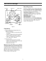
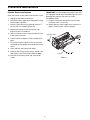
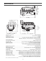
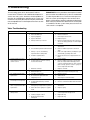
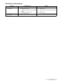
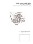
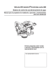
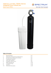
Autotrol® Performa™ FA Valve
With 400 Series Control
Water Conditioning Control System
Dealer Installation, Operation, and Maintenance Manual
Table of Contents
Installation . . . . . . . . . . . . . . . . . . . . . . . . . . . . . . . . 3
Location Selection
Water Line Connection
Drain Line Connection
Regenerant Line Connection
Overflow Line Connection
Placing Conditioner into Operation . . . . . . . . . . . . . 5
Electrical Connection
440i Control Settings . . . . . . . . . . . . . . . . . . . . . . . . 6
Programming
Manual Regeneration
Removing the Valve Assembly for Servicing . . . . . . 7
Removing 440i or 460i for Servicing . . . . . . . . . . . . 7
Preventive Maintenance . . . . . . . . . . . . . . . . . . . . . 8
Injector Screen and Injector
Specifications . . . . . . . . . . . . . . . . . . . . . . . . . . . . . 9
Pressure Graphs . . . . . . . . . . . . . . . . . . . . . . . . . . 10
Identification of Control Valving . . . . . . . . . . . . . . . 11
Valve Disc Principle of Operation . . . . . . . . . . . . . 11
Flow Diagrams. . . . . . . . . . . . . . . . . . . . . . . . . . . . 12
1 Service Position
2 Backwash Position
3 Draw/Slow Rinse Position
4 Fast Rinse/Refill Position
Replacement Parts . . . . . . . . . . . . . . . . . . . . . . . . 13
Performa Valve
440i Control
1265 Bypass
Troubleshooting . . . . . . . . . . . . . . . . . . . . . . . . . . . 15
2
Installation
All plumbing and electrical connections must conform
to local codes.
Inspect the unit carefully for carrier shortage or
shipping damage.
In
Not in Bypass
Out
In Bypass
Out
In
Location Selection
BY
PA S S
BY
PA S S
BY
BY
1. The distance between the unit and a drain should be
as short as possible.
PA S S
PA S S
2. If it is likely that supplementary water treatment
equipment will be required. Make sure adequate
additional space is available.
3. Since salt must be added periodically to the brine
tank, the location must be easily accessible.
Water
Conditioner
4. There should be at least 10 feet (3 m) of piping
between the outlet of the conditioner and the inlet
to the heater. Water heaters can sometimes
overheat and transmit heat back down the cold
pipe into the unit control valve.
Water
Conditioner
Figure 1 - Autotrol Series 1265 Bypass Valve
Hot water can severely damage the conditioner. A
10-foot (3-m) total pipe run, including bends,
elbows, etc., is a reasonable distance to help
prevent this from happening.To prevent hot water
flowing from heat source to the conditioner, in the
event of a negative pressure situation, install a
check valve in the treated water piping from the
conditioner. If a check valve is installed, make
sure the water heating unit is equipped with a
properly rated temperature and pressure safety
relief valve. Also, make sure that local codes
are not violated.
Not in Bypass
In Bypass
Water
Conditioner
Water
Conditioner
Water
Water
Figure 2 - Typical Globe Valve Bypass System
Drain Line Connection
5. Do not locate the unit where it or its connections
(including the drain and overflow lines) will ever be
subjected to room temperatures under 34oF (1oC)
or over 120oF (49oC).
Note: Standard commercial practices are followed
here. Local codes may require changes to the following
suggestions.
1. Ideally located, the unit is above and not more than
20 feet (6.1 m) from the drain. For such installations,
using an appropriate adapter fitting, connect
1/2-inch (1.3-cm) plastic tubing to the drain line
connection of the control valve.
6. Do not install the unit near acid or acid fumes.
7. The use of resin cleaners in an unvented enclosure
is not recommended.
Water Line Connection
2. If the backwash flow rate exceeds 5 gpm
(22.7 Lpm) or if the unit is located more than 20 feet
(6.1 m) from the drain, use 3/4-inch (1.9-cm) tubing
for runs up to 40 feet (12.2 m). Also, purchase the
appropriate fitting to connect the 3/4-inch tubing to
the 3/4-inch NPT drain connection.
The installation of a bypass valve system is
recommended to provide for occasions when the water
conditioner must be bypassed for untreated water or
for servicing.
The most common bypass systems are the Autotrol
Series 1265 bypass valve (Figure 1) and the plumbedin globe valves (Figure 2). Though both are similar in
function, the Autotrol Series 1265 bypass offers
simplicity and ease of operation.
3. If the unit is located where the drain line must be
elevated, you may elevate the line up to 6 feet
(1.8 m) providing the run does not exceed
15 feet (4.6 m), and the water pressure at
conditioner is not less than 40 PSI (2.76 bar). You
may elevate an additional 2 feet (61 cm) for each
additional 10 PSI (0.69 bar).
3
Overflow Line Connection
4. Where the drain line is elevated but empties into
the drain below the level of the control valve, form a
7-inch (18-cm) loop at the far end of the line so that
the bottom of the loop is level with the drain line
connection. This provides an adequate siphon
trap.
In the absence of a safety overflow and in the event of
a malfunction, the REGENERANT TANK OVERFLOW
directs “overflow” to the drain instead of spilling the
“overflow” on the floor where it could cause
considerable damage. This fitting must be on the side
of the cabinet or regenerant tank.
Note: Where the drain empties into an overhead sewer
line, a sink-type trap must be used.
To connect the overflow line, locate the hole on the side
of the regenerant tank. Insert the overflow fitting (not
supplied) into the tank and tighten the fitting with
plastic thumb nut and gasket as shown (Figure 4).
Attach a 1/2-inch (1.3-cm) length of I.D. tubing (not
supplied) to the fitting, and run it to the drain. Do not
elevate the overflow line higher than 3 inches (7.6 cm)
below the bottom of the overflow fitting. Do not
connect to the drain line of control unit. The overflow
line must be a direct, separate line from the overflow
fitting to the drain, sewer, or tub. Allow an air gap as per
drain line instructions (Figure 3).
IMPORTANT: Never insert the drain line into a drain,
sewer line, or trap. Always allow an air gap between the
drain line and the wastewater to prevent the sewage
from back-siphoning into the conditioner (Figure 3).
Right Way
Figure 3
Note: Standard commercial practices have been
followed here. Local codes may require changes to
these suggestions.
Overflow Fitting
Installed
Regenerant
Tank
Regenerant Line Connection
It is necessary to connect the regenerant line to the
fitting on the valve (3/8-inch NPT).
Connect 1/2-inch (1.3-cm)
Tubing or Hose and Run
to Drain
Make sure all fittings and connections are tight.
Figure 4
4
Placing Conditioner into Operation
carefully advance the indicator knob
COUNTERCLOCKWISE to the center of the
REFILL position. Hold the indicator knob at this
position until water starts to flow through the
regenerant line into the regenerant tank. Do not
run the unit for more than one or two minutes.
B. Advance the indicator knob
COUNTERCLOCKWISE until it points to the
center of the DRAW/SLOW RINSE position.
C. With the indicator knob in this position, check to
see if water is being drawn from the regenerant
tank. The water level in the regenerant tank
recedes very slowly. Observe the water level for
at least three minutes. If the water level does
not recede, or if it goes up, reference the
Troubleshooting section.
D. Advance the indicator knob
COUNTERCLOCKWISE to the SERVICE or
CONDITIONED WATER position and run water
from a nearby faucet until the water is clear and
soft.
After all of the previous steps have been completed, the
unit is ready to be placed into operation. Follow these
steps carefully.
1. Remove the control valve cover by first releasing the
plastic tab from the back of the cover. Pull the back
of the cover slightly outward and lift it up.
Note: The following steps will require turning the
indicator knob (Figure 5) to various positions.
Manually rotate the camshaft
COUNTERCLOCKWISE only until the indicator
knob points to required position. (See the manual
regeneration sections for each control’s manual
operation.)
2. Rotate the indicator knob COUNTERCLOCKWISE
until it points directly to the word BACKWASH.
3. Fill the media tank with water.
A. With the water supply off, place the bypass
valve(s) into the “not in bypass” position.
B. Open the water supply valve very slowly to
approximately the 1/4 open position.
6. Add the regenerant. Potassium permanganate is
normally used as the regenerant, however, other
regenerants that provide satisfactory results may
be used.
IMPORTANT: If the water supply valve is opened too
rapidly or too far, media may be lost. In the 1/4 open
position, you will hear air escaping slowly from the
drain line.
Electrical Connection
C. When all of the air has been purged from the
tank (water begins to flow steadily from the
drain), open the main supply valve all of the way.
D. Allow the water to run to the drain until it is clear.
E. Turn off the water supply and let the unit stand
for about five minutes. This allows all of the
trapped air to escape from the tank.
100 VAC, 115 VAC, and 230 VAC units: Remove the
twist tie from the power cord, and extend the cord to its
full length. Make sure the power source matches the
rating printed on the control. Make sure a wall switch
does not control the outlet.
12 VAC: Connect the plug of the transformer (supplied)
secondary cable to the mating socket at the rear or
bottom of the timer housing. Make sure the transformer
is secure and is plugged into a power source of correct
voltage that is not controlled by a wall switch.
4. Add water to the regenerant tank (initial fill).
With a bucket or hose, add water to the
regenerant tank. If the tank has a platform above
the bottom of the tank, add water until the level is
approximately 1 inch (25 mm) above the platform.
Do not add regenerant at this time.
5. Place the unit into operation.
A. With the water supply valve completely open,
5
440i Control Settings
Manual Regeneration
Day Arrow
Electricity is used only to run the control and to rotate
the camshaft. All other functions are operated by water
pressure. Therefore, in the event of a power outage, all
the regeneration positions may be dialed manually by
depressing the indicator knob and turning
COUNTERCLOCKWISE (Figure 5). The following
cycle times should be used for proper regeneration:
Skipper Wheel
Skipper Pins
BACKWASH—20 minutes
DRAW/SLOW RINSE—50 minutes
FAST RINSE/REFILL—10 minutes
DRAW
Do not exceed 10 minutes for the FAST RINSE/REFILL
cycle as this causes excessive regenerant usage during
the next regeneration and possibly a regenerant
residue in the treated water.
Indicator Knob
Timer
Locking Pin
Time Arrow
Timer Knob
Figure 5
Programming
1. Set the number of days of regeneration on the
skipper wheel (Figure 5).
• Pull all of the skipper pins outward (away from
the control).
• Rotate the skipper wheel until day arrow points
to the number of current day or number 1.
• Depress the skipper pin(s) at the day(s) for
which regeneration is required.
2. Set the time of day.
• Grasp the timer knob and pull it outward.
• Rotate it in either direction until the timer arrow
points to the actual time of day.
• Release the timer knob.
Note: With the time of day properly set, the conditioner
regenerates at about 2:30 a.m. If you prefer to have the
unit regenerate at an earlier or later time, simply set the
current time-of-day accordingly (e.g., to have the unit
regenerate at 4:30 a.m.—two hours later—set the clock
two hours earlier than the actual time of day.)
Note: The Timer Locking Pin should always be
horizontal (Figure 5) during operation.
6
Removing the Valve Assembly for Servicing
1. Unplug the power cord.
2. Shut off the water supply or put the bypass valve(s)
into bypass position.
Lever Down
3. Remove the cover, and with a screwdriver, relieve
tank pressure by pushing open valve No. 7 (rear
flapper) on the control as shown (Figure 10).
Figure 11
Lever Up
Figure 10
4. When used with a globe valve bypass, loosen and
detach the inlet, outlet, regenerant, and drain lines
from the valve. If using the 1265 bypass, loosen
and remove the valve from bypass as well as
loosening and removing the regenerant and drain
lines.
5. Unscrew the valve (counterclockwise) and remove
the valve from tank.
Cam Pulled Out
Figure 12
6. To replace the control valve, reverse the above
procedure.
6. Remove the timer locking pin and lift the control
straight up and off of the valve.
Removing 440i or 460i for Servicing
1. Unplug the power cord.
7. To reinstall the camshaft and control, reverse the
above procedures.
2. Remove cover.
Note: When reinstalling the camshaft the control
should be in SERVICE position. When the camshaft is
positioned, cams will make contact with valves to force
them open.
3. The control should be in service position
(Figure 11).
4. Rotate the locking lever to point up (Figure 12).
5. Pull the end of the camshaft out from the lever and
remove the camshaft.
7
Preventive Maintenance
Injector Screen and Injector
1. Unplug the wall-mount transformer.
IMPORTANT: Do not overtighten the plastic cap. Seat
the cap lightly into position. Overtightening may cause
breakage of the plastic cap that may not be
immediately visible.
2. Shut off the water supply or put the bypass valve(s)
into the bypass position.
11. Plug the wall-mount transformer into the outlet.
Reset the clock, if necessary.
3. Relieve system pressure by opening valve No. 7
(at rear) with a screwdriver (Figure 10).
12. Slowly open the water supply valve or return the
bypass valve(s) to the “service” position.
Clean the injector screen and the injector once a year:
4. Remove the injector screen and injector cap
(Figure 12) with a screwdriver.
5. Clean the injector screen using a fine brush. Flush
it with water until clean.
Injector Screen
6. Pull the injector straight out using a needle-nose
pliers.
7. Flush water into the injector screen recess of the
valve body to flush debris out through the injector
recess.
Turbine
8. Clean and flush the injector with water.
9. Lubricate the O-rings on the injector, injector cap,
and injector screen with silicone lubricant only!
Injector
10. Reinstall the injector, injector cap, and injector
screen.
Figure 13
8
Cap
Specifications
Hydrostatic Test Pressure . . . . . . . . . . . . . . . . . . . . . . . . . . . . . . . . . . . . . . . . . . . . . . . . . . . . . . . . 300 PSI (20.69 bar)
Working Pressure. . . . . . . . . . . . . . . . . . . . . . . . . . . . . . . . . . . . . . . . . . . . . . . . . . . . . . . . 20-125 PSI (1.38 - 8.62 bar)
Standard Electrical Rating . . . . . . . . . . . . . . . . . . . . . . . . . . . . . . . . . . . . . . . . . . . . . . . . . . . . . . . . . . . . . . . 12V 60 Hz
Optional Electrical Rating . . . . . . . . . . . . . . . . . . . . . . 115V 50 Hz, 230V 50 Hz, 200V 60 Hz, 24V 60 Hz, 24V 50 Hz,
100V 60 Hz, 100V 50 Hz, 12V 50 Hz/transformer, 12V 60 Hz/transformer
Pressure Tank Thread . . . . . . . . . . . . . . . . . . . . . . . . . . . . . . . . . . . . . . . . . . . . . . . . . . . . . . . . . . . . 2 1/2 inch-8 male
Riser Pipe Diameter Required . . . . . . . . . . . . . . . . . . . . . . . . . . . . . . . . . . . . . . . . . . . . . . . . 1.050 inch OD (26.7 mm)
Riser Pipe Length . . . . . . . . . . . . . . . . . . . . . . . . . . 1-1/8 ±1/8 inches (31.8 mm) higher than the top of mineral tank
Standard Connection . . . . . . . . . . . . . . . . . . . . . . . . . . . . . . . . . . . . . . . . . . .1-inch (25.4-mm) copper tube adapters
Optional Connections . . . . . . . . . . . . . . . . . . . . . . . 3/4-inch, 1-1/4-inch, 22-mm, and 28-mm copper tube adapters
3/4-inch BSPT, 1-inch BSPT, 1-inch NPT brass pipe adapters
3/4-inch, 1-inch, 25-mm CPVC tube adapters
Regenerant Line Connection . . . . . . . . . . . . . . . . . . . . . . . . . . . . . . . . . . . . . . . . . . . . . . . . . . . . . . 3/8-inch NPT male
Drain Line Connection . . . . . . . . . . . . . . . . . . . . . . . . . . . . . . . . . . . . . . . . . . . . . . . . . . . . . . . . . . . 3/4-inch NPT male
Optional Bypass Valve. . . . . . . . . . . . . . . . . . . . . . . . . . . . . . . Rotating handles, full 1-inch porting, reinforced Noryl*
Control Module, Tank Adapter. . . . . . . . . . . . . . . . . . . . . . . . . . . . . . . . . . . . . . . . . . . . . . . . . . . . . . . Reinforced Noryl
Rubber Goods . . . . . . . . . . . . . . . . . . . . . . . . . . . . . . . . . . . . . . . . . . . . . . . . . . Compounded for cold water service
Program Clock (Timer). . . . . . . . . 440i: Available in 6- or 7-day English, German, French, Italian, Spanish, Japanese
Injector Size “A” White . . . . . . . . . . . . . . . .Nozzle 042-inch (1.1-mm) diameter, Throat .089-inch (2.3-mm) diameter
Injector Size “B” Blue . . . . . . . . . . . . . . . . Nozzle .052-inch (1.3-mm) diameter, Throat .099-inch (2.5-mm) diameter
Injector Size “C” Red. . . . . . . . . . . . . . . . . Nozzle .059-inch (1.5-mm) diameter, Throat .099-inch (2.5-mm) diameter
Injector Size "D" Green . . . . . . . . . . . . . . . Nozzle .071-inch (1.8-mm) diameter, Throat .147-inch (3.7-mm) diameter
Internal Backwash Controllers. . . . . . . . . . . . . . . . 7- through 14-inch (17.8- though 35.6-cm) diameter media tanks
All sizes to flow 5.0 gpm/sq ft (183 L/m/m2) of bed area.
For tank sizes above 14 inches in diameter, use an external flow control.
* Noryl is a trademark of the General Electric Company.
9
Pressure Graphs
Injector #1031363
Injector #1031364
"A" in a 268 Valve
"B" in a 268 Valve
1.00
0.30
0.20
Total
1.25
0.25
0.75
1.00
0.20
Rinse
Rinse
0.50
Regenerant Draw
0.05
0.00
0.15
0.75
GPM
M3/hr
0.10
GPM
M3/hr
0.15
Total
0.10
0.50
0.05
0.25
0.00
0.00
Regenerant Draw
0.25
0.00
20
40
400 600
60
PSI
80
100
120
20
800 1000 1200 1400 1600 1800
bar
40
400 600
60
Rinse
0.20
0.10
0.05
M3/hr
1.00
GPM
M3/hr
0.25
Total
0.75
0.10
Regenerant Draw
0.50
0.05
0.25
0.00
0.15
0.00
0.00
20
40
400 600
60
PSI
80
100
2.25
2.00
1.75
1.50
1.25
1.00
0.75
0.50
0.25
0.00
Total
Rinse
GPM
0.30
1.25
120
"D" in a 268 Valve
1.75
0.15
100
800 1000 1200 1400 1600 1800
bar
"C" in a 268 Valve
1.50
80
Injector #1030272
Injector #1031365
0.20
PSI
Regenerant Draw
20
120
40
400 600
800 1000 1200 1400 1600 1800
bar
60
PSI
80
7
8
9
10
12
13
14
Flow (GPM*)
1.3
1.7
2.2
2.7
3.4
4.5
5.3
Flow (LPM*)
4.9
6.4
8.3
10.2
12.9
17.0
20.0
10
120
800 1000 1200 1400 1600 1800
bar
Backwash Number
*Approximate flow rates at 60 PSI (4.14 bar)
100
Control Valve
Identification of Control Valving
Valve Disc Principle of Operation
6 Rinse Drain Valve
7 Backwash Drain Valves
4 Outlet Valve
2 Bypass Valve
5 Refill Valve
1 Brine Valve
3 Inlet Valve
11
Flow Diagrams
1 Service Position
2 Backwash Position
Hard Water
Hard Water
Soft Water
Soft Water
Inlet
Inlet
3
3
2
2
5
5
Outlet
Outlet
4
6
4
Drain
Mineral Tank
Regenerant Tank
Regenerant Tank
4 Fast Rinse/Refill Position
3 Draw/Slow Rinse Position
Hard Water
Hard Water
Soft Water
Soft Water
1
Mineral Tank
Regenerant
Adjustment
1
Mineral Tank
Inlet
3
2
5
4
Regenerant
Adjustment
Inlet
3
2
Outlet
Backwash
Flow
Control
Drain
Valve
No.
1 - Closed
2 - Open
3 - Closed
4 - Open
5 - Closed
6 - Closed
7 - Open
Mineral Tank
7
6
7
Valve
No.
1 - Closed
2 - Closed
3 - Open
4 - Open
5 - Closed
6 - Closed
7 - Closed
5
6
Outlet
7
Drain
Valve
No.
1 - Open
2 - Open
3 - Closed
4 - Closed
5 - Closed
6 - Open
7 - Closed
Regenerant
Adjustment
1
Regenerant
Adjustment
1
Valve
No.
1 - Closed
2 - Open
3 - Open
4 - Closed
5 - Closed
6 - Open
7 - Closed
Mineral Tank
Regenerant Tank
4
6
Drain
Mineral Tank
12
7
Regenerant Tank
Replacement Parts
Performa Valve
4
5
13
2
13
15
14
9
10
3
1
6
7
12
8
11
* Not Shown
Part
Code
Part
Qty.
Code
1
1035606
No.
Valve Assembly, w/o Flow Controls
1
8
1033441
Refill Cap
1
2
1030376
Camshaft, 440i
1
9
1002449
Drain Fitting Elbow (3/4” hose barbed)
1
3
1031391
Timer Locking Pin
1
10
1000226
Screen/Cap Assembly
1
Drain Control Assembly:
1
11
1010429
O-Ring
1
1035622
Tank Ring
1
Plumbing Adapter Kits:
1
4
5
Description
No.
Description
1000209
No. 7 (1.2 gpm; 4.5 Lpm)
12
1000210
No. 8 (1.6 gpm; 6.1 Lpm)
13
1000211
No. 9 (2.0 gpm; 7.6 Lpm)
1001606
3/4-inch Copper Tube Adapter Kit
1000212
No. 10 (2.5 gpm; 9.5 Lpm)
1001670
1-inch Copper Tube Adapter Kit
1000213
No. 12 (3.5 gpm; 13.2 Lpm)
1041210
1-1/4-inch Copper Tube Adapter Kit
1000214
No. 13 (4.1 gpm; 15.5 Lpm)
1001608
22-mm Copper Tube Adapter Kit
1000215
No. 14 (4.8 gpm; 18.2 Lpm)
1001609
28-mm Copper Tube Adapter Kit
1030502
Ball, Flow Control
1
1001613
3/4-inch CPVC Tube Adapter Kit
Injector Assembly:
1
1032970
“A” Injector - White
6
1001614
1-inch CPVC Tube Adapter Kit
1001615
25-mm CPVC Tube Adapter Kit
1032971
“B” Injector - Blue
1001769
3/4-inch NPT Plastic Pipe Adapter Kit
1032972
“C” Injector - Red
1001603
1-inch NPT Plastic Pipe Adapter Kit
1030272
“D” Injector - Green
1001604
3/4-inch BSPT Plastic Pipe Adapter Kit
7
Injector Cap Assembly:
1
1001605
1-inch BSPT Plastic Pipe Adapter Kit
1000217
“A” Cap
3023824
3/4-inch BSPT S.S Pipe Adapter Kit
1000218
“B” Cap
3023828
1-inch NPT S.S Pipe Adapter Kit
1000219
“C” Cap
3023807
1-inch BSPT S.S Pipe Adapter Kit
1030303
“D” Cap
14
1235339
*
*
15
13
Spring, One Piece, 268
Qty.
1
Valve Disc Kit:
1041174
Standard
1041175
Severe Service
3019870
3019874
I-Lid Cover
Lever, Locking Cam 268
1
1
440i Control
DRAW
1
1265 Bypass
Part
B Y PA S S
Code
No.
B Y PA S S
Description
440i Control (6 day or 7 day)
1
Qty.
1
2
1040930 1265 Bypass
1
*
1000811 Transformer (440i, 460i):
1000907 Transformer Extension Cord
1
*
1
15 feet (4.6 m)
2
*
1034264 Y-Splitter (run 2 units from
1 transformer)
* Not Shown
14
1
Troubleshooting
The technology upon which the Autotrol Performa
control valve is based is well established and proven in
service over many years. However, should a problem or
question arise regarding the operation of the system, the
control can very easily be serviced. For parts mentioned,
refer to exploded views in the Replacement Parts section
of this manual.
IMPORTANT: Service procedures that require the water
pressure to be removed from the system are marked with
a ! after the possible cause. To remove water pressure
from the system, put the bypass valve or three-valve
bypass into the bypass position and open the backwash
drain valve (the seventh valve back from the control) with
a screwdriver. Restore system water pressure when the
service work is completed.
Valve Troubleshooting
Problem
1. Control will not draw.
Possible Cause
a.
Solution
Low water pressure.
a.
Set pump to maintain 30 PSI at unit.
b. Restricted drain line.
b.
Remove restriction.
c.
Injector plugged
!
d. Injector defective
!
c.
Clean injector and screen.
d.
Replace injector.
e.
Valve (2 and/or 4) not closed.
e.
Remove foreign matter from disc and check
disc for closing by pushing in on stem. Replace
if needed.
a.
Regenerant valve (1) being held open.
a.
Manually operate valve stem to flush away
obstruction.
b.
Remove variable regenerant controller to
clean.
c.
Flush out foreign matter by holding disc open
and manually operating valve stem.
d. Air leak in regenerant line.
d.
Check all connections in regenerant line for
leaks.
3. System using more or less
regenerant than regenerant
control is set for.
a.
a.
Correct setting.
b.
Remove variable regenerant controller and
flush out foreign matter. Manually position
control to regenerant draw to clean controller
(after so doing, position control to “purge” to
remove regenerant from tank).
c.
Defective controller.
c.
Replace controller.
4. Intermittent or irregular draw.
a.
Low water pressure.
a.
Set pump to maintain 30 PSI at unit.
b. Defective injector !
b.
Replace both injector and injector cap.
5. No conditioned water after
regeneration.
a.
a.
Check for power.
b.
Add chemical.
Clean injector. Flush with water.
2. Regenerant tank overflow.
b. Uncontrolled regenerant refill flow rate
c.
!
Valve (3 or 4) not closed during
regenerant draw causing refill.
Inaccurate setting.
b. Foreign matter in controller causing
incorrect flow rates !
Unit did not regenerate.
b. No chemical in regenerant tank.
c.
Plugged injector !
c.
6. Control backwashes at
excessively low or high rate.
a.
Incorrect backwash controller used.
a.
Replace with correct size controller.
b. Foreign matter affecting controller
operation !
b.
Remove controller and ball. Flush with water.
7. Flowing or dripping water at
drain or regenerant line after
regeneration.
a.
a.
Manually operate valve stem to flush away
obstruction.
b. Valve stem return spring on top plate
weak.
b.
Replace spring.
8. Unconditioned water leakage
during service.
a.
a.
Repeat regeneration making certain that the
correct regenerant dosage is set.
b. Leaking of bypass valve !
b.
Replace O-ring.
c.
c.
Replace O-ring.
Drain valve (5 or 6) or regenerant valve (1)
held open by foreign matter or particle.
Improper regeneration.
O-ring around riser tube
damaged !
15
440i Control Troubleshooting
Problem
1. Control does not regenerate
automatically.
2. Control regenerates at wrong
time of day.
Possible Cause
a.
Transformer or motor not connected.
Solution
a.
Connect power.
b. Defective timer motor.
b.
Replace motor.
c.
c.
Depress pins for days regeneration required.
d. Binding in gear train of timer.
d.
Replace timer.
a.
a.
Correct time setting according to instructions.
Skipper pins not down on timer skipper
wheel.
Time set incorrectly.
© 2008 Pentair Residential Filtration, LLC
P/N 1230232 Rev. C JA09