1
"
I
SNOWMOBILE
SERVICE MANUAL
TABLE OF CONTENTS
\_)
1973 BRUT SNOWMOBILE
2
ENGINE TIMING
20
BRUT'S LIQUID COOLED ENGINE
2
SERVICING DRIVEN CLUTCH
20
BRUT SPECIFICATIONS
3
SERVICING DRIVE CLUTCH
20
3
SKAG REPLACEMENT
21
BRUT SERVICE TOOL LISTING
3
HEADLIGHT REPLACEMENT
21
BRUT SNOWMOBILE CUTAWAY
3
HEADLIGHT ADJUSTMENT
21
1972 LC44 ELECTRICAL SCHEMATIC
4
TAILLIGHT-BRAKE LIGHT REPLACEMENT
21
1973 LC29 ELECTRICAL SCHEMATIC
5
BRAKE ADJUSTMENT
21
1973 LC44 ELECTRICAL SCHEMATIC
6
DRIVE BELT REPLACEMENT
21
SUSPENSION
7
CLUTCH ALIGNMENT
22
DRIVE SHAFT REMOVAL
7
RIDE ADJUSTMENT
INVOLUTE DRIVE SPROCKET REMOVAL
8
SPRING TENSION
22
CLUTCH REMOVAL
8
SHOCK TENSION
22
DRIVE INSTALLATION
8
TRACK ADJUSTMENT AND ALIGNMENT
23
BRAKE INSTALLATION
9
DRIVE CHAIN ADJUSTMENT
23
SUSPENSION INSTALLATION
9
COOLING SYSTEM
24
ENGINE TIMING
\___)
\
)
/
ENGINE REMOVAL
10
LUBRICATION
24
ENGINE DISASSEMBLY
12
FUEL MIXTURE
24
ENGINE ASSEMBLY
14
GASOLINE
24
PISTON RING INSTALLATION
17
OIL
24
THROTTLE ROD ADJUSTMENT
20
FUEL MIXING RATIO
24
CHOKE LINKAGE ADJUSTMENT
20
MIXING INSTRUCTIONS
24
STEERING ADJUSTMENT AND SKI ALIGNMENT
20
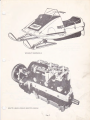
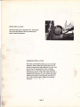
1973 BRUT SNOWMOBILE
BRUT'S LIOUID_COOLED BROOTEN ENGINE
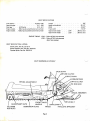
BRUT SPECIFICATIONS
Fuel capacity .
Spark plug gap
Point gap . .
Engine models.
Engine models .
. 5gallons (US)
.017 . .020
(LC29 only)
.012 - .017
294cc liquid-cooled Brooten twin-cylinder
439cc liquid-cooled Brooten three-cylinder
Length . . . . .
Height w/windshield
Width . . . . .
Track width . . .
Approximate weight
Approximate weight
LC44
LC29
102"
.35-1/2"
. 33-3/4"
. 15-1 /2"
. 395 lbs. (dry)
. 355 lbs. (dry)
ENGINE TIMING: LC44- 3.5mm BTDC fully-advanced
LC29 - 3.5mm BTDC fully-advanced
.6mm fully-retarded
BRUT SERVICE TOOL LISTING:
Clutch puller, Part No. 23112-11
Clutch alignment tool, Part No. 23122-10
Flywheel puller, Part No. 23123-10
BRUT SNOWMOBILE CUTAWAY
DRIVE CHAIN
CARBURETORS
DRIVE CLUTCH
FRONT IDLER'
ADJUSTMENT NUTS
WHEELS
' DRI
TIE DOWN
SUSPENSION SLIDE
TRACK
ROD NUTS
Page 3
INVOLUTE SPROCKET
c
c
(~
BROWN
~
LIGHT SWITCH
I~
GREEN
Y&:.Ll.O\..ftj
ENGINE
r---
Ys-L...L-ov....>
RED
'1.../I!!...LLOv..l
TAIL LIGHT
BL.AC...K
r)
l
r
'E<-L.ow/auo.c.K
i
.j:l.
YE.LLoW
BL"--IK---
TACHOMETER
r
Y~LLow/'BLA.C.K.
r
I
r
I.
I
BRI::>WN
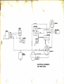
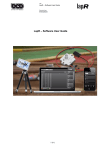
ELECTRICAL SCHEMATIC
1972 BRUT (440)
i
I·
•f
..
I
~;'
_,.• _:1 -~,(-.";A;,
, -'·'-...
~·~·; · · ·· /, _._ . ~!...,..~t.
'
~:........_
_';'\·
,_
. ,,
'f: ·_f
:(~~,~~ .....
'{ l.t ::·-,,
\~·<;
\ ·~\
"<!il
~'¥.-+
}
._
HEAQLIGHT
LIGHT SWITCH
IGNITION
Gl'iiE:.E-N.
SWITCH
~
U§J.H
Ret>
~I
IIELLOW
,
TAIL LIGHT
~
'-'El...L()\1.1
>,!i
YILLLOW ( RILD
RED
HI"T£
YEL\.OYJ llilt.AC.K
""0
Ill
'i
U1
YEL'-0""1
TACHOMETER
~
REGULATOR
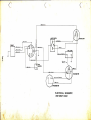
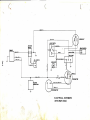
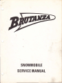
ELECTRICAL SCHEMATIC
/973 BRUT (294)
( ~\
c
~--~------~
('
~
~--~~-
1
r
(~'
C.'
(
"f
'/' .
ROMJN
\
HEADUGHT
YE.L.LOW
LIGHT SWITCH
IGNITION
SWITCH
G.RE:.~
,....--
., \
ENGINE
r--
L-ACK;
~t:>
L.L-0\Jo.J
....-'lo.L-L.O\IV
lLEc;
KILL SWITCH
· "tt
Ill
'fil
3
BLACK.
C)
0
~
._,.ELL.L.OW
TACHOMETEit
YE.LLO\AJ / B~K.
VOLTAGE
REGULATOR
BROw r-J
:PEEDOMETER
=
ELECTRICAL SCHEMATIC
1973 BRUT (440)
L
1(':
4,.,
~
f
AI
~,,):,; '
J;'l i~~·f
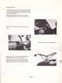
SUSPENSION
Remove suspension. To remove suspension remove the
four (4) 3/8" locking bolts mounting suspension to chassis.
Plug air bleed hole in gas cap, turn machine on to one side.
Then pull out suspension.
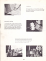
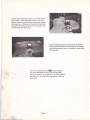
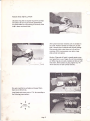
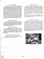
DRIVE SHAFT REMOVAL
To remove drive shaft, the chain case must be removed
and the suspension must be removed. On the left side of
the machine is a locking collar positioned on the spherical
bearing in the flangette. (Photo at right) Loosen allen
screw, turn collar opposite way it was installed. Note
punch mark in locking hole. Slide collar over shaft, then
push shaft into chain case hole and pull out bottom.
Chaincase assembly must be removed before drive shaft
can be removed. (Two photos below) Remove chain case
drive elements. Remove chain by removing snap ring on ,
upper sprocket and bolt on lower sprocket. Remove
chain tensioner by backing out tightener bolt.
Page 7
, _.,. r
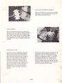
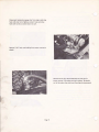
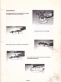
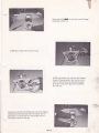
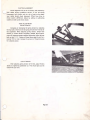
INVOLUTE DRIVE SPROCKET REMOVAL
With drive shaft removed, remove the involute sprocket.
With long 1/4" punch, pound out 5/16" roll pin from
shaft. Drive sprocket should slide off.
CLUTCH REMOVAL
Remove three (3) Phillips head screws holding bumper
and hood extrusion onto nosepan on left side of machine
only. Remove 5/8" head clutch bolt, then special large
nut on clutch. Thread clutch puller into threads of special
end nut. Bearing on end of puller will press against end
of crankshaft and pull clutch, by tightening puller against
crankshaft.
DRIVE INSTALLATION
Slip snap ring on top drive sprocket in chaincase to hold
it in position. Install chain tightener assembly. and
tighten chain so there is 1/2" deflection in chaintlam
locking nut on tightener bolt. Check "0" ring seal on
chaincase cover and install if O.K. Be careful not to
damage jackshaft seal when installing chaincase cover.
Lock collar must be on flangette side of shaft with
eccentric portion facing tunnel before installation.
Before installing chaincase, be sure snap ring is on
shaft. With machine laying on left side, fit track into
tunnel. Then push driveshaft into chaincase hole
and back through spherical bearing mounted on
the flangette. Holding drive sprockets as close to
center of tunnel as possible slide chaincase onto
drive'shaft. Snug chaincase tightly up against tunnel.
Slide top sprocket spacer over spline and install
sprockets and chain. Screw bolt in driveshaftto
hold chain sprocket on and center involute drive
sprockets.
Go,back to driveshaft inside tunnel and slide lock collar
into position next to flangette bearing. Turn collar lock
with punch and tighten with allen wrench.
Page 8
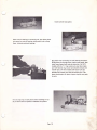
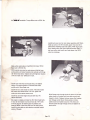
BRAKE INSTALLATION
Place inner brake puck in chaincase cover. Install brake
disc, then brake assembly. Make sure actuating pin
points toward actuating lever.
,,
SUSPENSION INSTALLATION
h~
'
With track and driveshaft installed, you can now install
suspension. Raise machine rear approximately 30" off
ground on secure stand. Slide suspension into track. Line
up front two (2) mounting bolts, insert and tighten.
Slide a 2"x2" or 2"x4" block under track, positioned
just behind second set of front idler wheels. Drop rear of
machine down. Push down or up on machine rear while
holding rear suspension mounting shaft until shaft is in
line to insert mounting bolts. Tighten bolts and align
suspension. 3 e e
p , ;L 3
Page 9
--- -
-
------
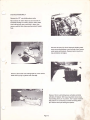
ENGINE REMOVAL
Loosen linkage rod tie down screws on choke and throttle
on carb next to water pump. Loosen cable tie down screw
on choke cable housing. Remove throttle cable at throttle
lever next to handle grip.
Disconnect fuel supply and return line at carburetor.
Disconnect impulse line on carb next to water pump.
Remove 3/8" nut holding tie rod ends to steering post
frog .
Remove cotter key at base of steering post .
..
Remove two (2) 1/4" nuts at upper steering yoke. Lift
steering post away from engine compartment.
Disconnect COl unit lead to engine. Disconnect the
two (2) yellow lighting wires and black ground wire
leading from stator unit. Disconnect spark plug leads.
Page 10
Disconnect temperature gauge line from engine and plug
hole with small cork. Remove coolant hoses and plug
holes with corks so coolant does not spill.
Remove 7/16" lock nuts holding front motor mounts to
chassis.
Remove the six (6) 12mm head bolts on rear pair of
motor mounts. Lift engine and drain coolant. Be careful
not to let engine drop and break the plugs during removal.
Page 11
ENGINE DISASSEMBLY
Remove the 1/2" nuts holding down carbs.
Next remove the 12mm head nuts and one bolt in
crankcase holding on muffler. Remove 10mm head
nuts holding both water manifolds in place, then
remove manifold after disconnecting coolant bypass
hose.
Remove the three (3) 12mm head bolts holding water
pump mounting brackets to end cylinder, then remove
water pump and brackets. Remove motor mounts on
top and bottom of engine.
Remove 12mm head nuts holding heads on, then remove
heads while prying up gaskets with flat edge.
Remove 14mm nuts holding down cylinders and slide
cylinders off pistons. With snap ring pliers remove snap
ring holding piston pin in position. Don't apply excessive
side pressure on connecting rod while removing piston
pin. Remove wrist pin bearing and spacers.
Page 12
Remove 10mm head bolts holding on recoil and take off
recoil. Remove 10mm head bolts holding on belt pulley
Remove 10mm head bolts holding on dust cover. Remove
30mm head nut on flywheel and install 10mm head bolts
furnished with flywheel puller and a 27mm socket for the
flywheel puller and remove rotor.
Remove Phillips head screws on special seal on flywheel
side and remove seal. Bend lock tabs back on 12mm head
bolts holding seal plate on end of crankshaft, remove bolts,
then seal plate.
~. -··.
Now you can disassemble crank~ Remove eighteen
(18) 12mm head bolts and two (2) 14 mm head bolts
with plastic hammer, tap on one half of crankcase, holding
the other half in one hand. When case separates, shaft can
be removed.
Page 13
ENGINE ASSEMBLY
Lay crankcase lower half on workbench. Place crankshaft
in crankcase. Install rotor key in crankcase.
Grease labyrinth seal and oil bearings.
Install spacer ring next to ball bearings on flywheel side.
Smear gasket sealer on upper joining half of crankcase and
fit onto lower half carefully.
Page 14
1
Tap clutch end of shaft with plastic hammer to position
shaft correctly in case .
Install eighteen (18) 12mm head bolts and two (2) 14mm
head bolts and torque-tighten according to pattern in
illustration below.
~
~
~
~
i
!
:
5
•
!
i!
:o
-r
~
~
1~ ~-----------------------------------J
y
Torque 14mm heads to 25ft. lbs.
Torque 12mm heads to 18ft. lbs.
With depth micrometer, measure from seal plate mounting
surface on case to outer race of shaft ball bearing.
Choose from three (3) thicknesses of gaskets to place
under seal plate. If micrometer measures from .091 and up,
use .2mm (.008"); if it measures from
to .091, use
.3mm (.012); if it measures from .080 and down, use .5mm
(.020"). Install correct gasket and seal plate, tend lock tabs
over plate bolts.
:IIi
Page 15
v--1-4m-m"""'l
~------'-
Install cylinder base gasket.
Place wrist pin bearing in connecting rod, then place piston
pin spacers on ends of bearings, being careful not to drop
them. Lubricate wrist pin bearings.
Slip piston over connecting rod with bearing and spacer.
Slide piston pin through piston, bearing and spacer, then
install snap rings at both ends of piston pin. On 1973
models with the "L" ring, locator pin must face intake
port with second ring, locator pin between exhaust and
transfer port. On 1972 models both locator pins are
between the transfer ports and the exhaust port. This
places locating pins for piston rings so rings do not catch
in ports.
Put one snap ring on each piston before installing on rod
so you don't have to squeeze on between two pistons.
Page 16
,.
;
PISTON RING INSTALLATION
Use piston ring pliers to expand ring until it just slips
over piston. Be sure ring is correctly positioned so
ring notch slides into ring locating pin correctly. With
rings in place, set pistons aside.
After pistons have been installed, bolt on cylinders in
any order. Position cylinders so intake port; or carb
side, is toward side of crankcase with impulse fittings.
Place wooden block under 'piston so it sits solid on
crankcase. With ring compressor over piston rings,
slide cylinder onto piston.
Caution: Ring ends will catch in transfer ports so you
must press them in your fingers. Do not force cylinders
on! When rings do not catch, cylinder will slide on with
little effort. With cylinders in place, tighten four (4)
14mm head nuts on each cylinder securely.
\
Put water manifold on cylinders and torque 1 Omm
head nuts to 60 inch lbs.
Install heads and torque nuts to 17ft. lbs. according to
the followin!l torque pattern :
'
4.
2.
6
•
HEAD
TORQUE
•
.1
.3
5
Page 17
L_ _ _
..
~
Grease and install~ on recoil side. Install flywheel
and torque to 60ft. lbs.
( LC29) Mount stator plate in center of slots.
(LC29) Coat breaker cam with thin coat of grease.
Connect timing equipment, light, buzzer or ohm
meter to white primary lead, adjust point gap to
get correct timing. Point gap should be between
.011 and .017.
Install stator with three (3) Phillips head screws after aligning
installing holes with machined holes in crankcase. (Do not
force stator in, it should slide in by hand snugly. Do not
rotate stator, holes must line up!)
Page 18
·.;
'
I
I
I
'I
i
r o+o r- ol1
Key..._ e crankshaft. Torque 30mm nut to 55 ft. lbs.
Install dust cover next to rotor stator assembly with 10mm
head cap screws. On 1972 models, spacer ring must be in
place before installing lower belt pulley. With ring in position, install pulley with 10mm head cap screws. Slide "v"
belt over pulley and install recoil and spacer ring (1972
only) on crankcase .
. Sjide outlet water pipe on manifold c.nd torque 1Omm
·
}:.'head
nuts to 60 inch lbs .
.,
.:..
-~
' With brackets mounted on water pump, slide belt over
pump pulley and screw brackets onto cylinder with three
(3) 12mm head bolts. Tighten belt with tightener bracket
until you reach 1/2" deflection in belt,
Install water inlet hose and bypass hose, and tighten
clamps. Fit exhaust gasket on manifold and install
muffler with 12mm head nuts.
Install the two carbs closest to clutch. Throttle bracket
fits under carb nearest clutch. The 1/4" spacer fits
under two carbs nearest water pump.
Install two (2) lower engine mounts with four (4)
14mm head bolts.
..
Set engine in chassis and install six (6) 12mm head bolts
in two (2) rear engine mounts and two (2) 7 /16" bolts
on front mounts. Set steering post in position and
fasten all bolts. Install third carb next to water pump.
Install throttle cable on cable bracket mounted toward
center of threads.
Slide linkage rods through choke tie downs on the two
carbs closest to flywheel and loop cable around carb
closest to clutch. Replace tie-down screw after looping
over linkage swivel. Mount choke cable on choke
cable bracket and tighten securely. Pull choke and
throttle cables through linkage swivel and tighten tie
down screw.
Page 19
THROTTLE ROD ADJUSTMENT
lead to grounding surface ~>n engine. Insert a dial
indicator in spark p lug hole nearest flywheel.
Loosen linkage 'rod tie down screws on the two carburetors
closest t~ clutch . Squeezing the throttle, the linkage rod
should move freely inside tie downs without activating
the throttle shafts on these ~wo carbs.
sho,· adj~~~er
Position pole
on stator plate in center of
slots. (Note: It i ~ be~t'to set correct timing with stator
in this position. ;But' if timing will not come into specs
without having t he point gap out of tolerance~. then
pole shoe adjuster on stator must be changed.)
Back out all carbu retor idle speed screws away from carb
throttle shaft stops. This will synchronize all butterflies
in closed position. Grasp linkage rod and push it hard
enough so first carb butterfly closes completely. The other
two carbs should be closed also. When they are all closed,
continue to hold down rod and tighten tie down screws
securely. Move throttle lever to check synchronization of
all throttle shafts. If synchronized, turn idle speed screws
until they just touch shaft stops, then make an additional
3/4 turn on each screw. You must turn them more for
proper idle but this should be done with engine running.
To set correct idle speed of 1500 rpm, you must turn idle
screws on all carburetors exactly the same amount.
Adjust point gap on points open when dial indicator
reads .6mm or .024" in the cam retarded or static
position . If you have fully advanced cam under
flywheel, then dial indicator should read 3.5mm
or .138" at correct timing setting.
Check point gap with feeler gauge and make sure point
gap is within specs of .012" and .017". If not, stator
plate must be adjusted accordingly to set proper specs.
When timing is correct on flywheel cylinder, next set
timing on cylinder next to clutch. Disconnect white
lead to coil. Adjust timing by changing point gap only.
If stator plate is moved, flywheel cylinder must be
retimed.
CHOKE LINKAGE ADJUSTMENT
Make choke adjustments the same as throttle so choke
butterflies are all closed when choke cable is pulled .
Then, when choke is pushed in, butterflies will open all
the way.
SERVICING DRIVEN CLUTCH
STEERING ADJUSTMENT AND SKI ALIGNMENT
Position removed clutch with fixed face down. Rotate
moveable sheave approximately 35c clockwise and hold
steady. Press stationary helix down to clear key and
rotate so key holds helix down. Remove snap ring,
then rotate helix into snap ring groove. Hold firmly
to prevent sudden spring release.
Position handle bars so they face straight ahead. Adjust
either ski so it is also facing straight ahead. Adjust ski
by loosening jam nuts at both ends of tie rod either
direction to align one ski. If you cannot align one
ski exactly, you may have to index steering arm at
spindle. When both handle bars and one ski are aligned,
measure distance from one ski to other at points on
front and rear ski spring saddles. There should be 1/4"
toe out, that is, front of skis are spread 1/4" farther
apart than rear. If you do not have correct toe out,
loosen jam nuts on tie rod that has not been adjusted
and turn whichever way necessary to get 1/4" toe
out. When steering is adjusted, make sure all jam nuts
and other nuts and bolts are tight.
·
Clean and examine all parts. Replace if worn . Slide
moveable face onto hub, replace key. Engage spring
with anchor point in torque bracket and anch'or ·point
in moveable face. Compress spring until 1/16" to
1/8" shows between ramps. Rotate moveable face
1/3 turn or 120° counter clockwise after clock spring
tension is taken up. Push stationary helix down hub
shaft and lock under key. Replace snap ring. Release
stationary helix to seat against snap ring.
ENGINE TIMING
SERVICING DRIVE CLUTCH
LC44- The LC440 engine is equipped with capacitor
discharge ignition (CDI) and timing is set in the factory
at 3.5MM BTDC. in fully advanced position. Timing
cannot be adjusted on this system and should never
change.
Disassemble drive clutch by removing special large
end nut and installing clutch puller in clutch. Grab
moveable face with cover assembly firmly with one
hand and turn puller !Jntil clutch comes off.
#f''h - '
Holding moveable face"ofc lutch in both hands and
puller facing floor, tap puller against a f irm object.
It should seMrate,from stationary hub. Remove puller
and clutch will come apart.
-
LC29- The LC294 engine is equ i pped with flywheel
magneto ignition system. Timing is factory set at 3.5mm
BTDC in fully advanced position and .6mm fully
retarded position .
.
$P''
Inspect clutch arms to make sure they are not
sticking. Clean and examine all parts. Replace if worn.
When assembling clutch, note balance lines on cover
and moveable face. They must line up after assembly.
To set timing, disconnect red wire leading from ignition
points to ignition coil on cylinder next to flywheel.
Connect one lead of an ohmmeter, timing light or
timing buzzer on connector leading from points.
Connect other
Page 20
';~~
'l.. . ..-.
..- i'
BRAKE ADJUSTMENT
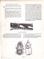
SKAG REPLACEMENT
The skag is a wear bar attached to each ski bottom to aid
in turning and prevent wear on actual ski blade. Check condition of skag wear often and replace skags when worn down
near ski. To replace, remove nut holding skag in place. With a
solid bar, bend skag outward until bolt is free from its ski hole.
Place a 1" piece of wood between skag and ski blade, just
behind front ski bolt. With hammer, tap on wooden block,
forcing skag forward until back pops out of slot. With new
skag, push front sloped end into front ski slot, with 1" wooden block positioned in front of rear skag bolt. While guiding
rear of skag toward rear skag hole by hand, tap on wooden
block, to drive skag backwards. When skag bolts line up directly with holes, use pry bar to remove wooden block and skag
will snap into place. Then replace lock nuts and skag bolts.
You r Brut caliper-disc brakes were preset at the factor)
and checked by your dealer in his setup procedure. No adjust~
ment should be necessary for the first 100 miles. After this
break-in period_. brakes should be checked each day of operation for approximately 3/4" free travel of the brake handle.
There are two met hods to adjust brakes in order to move disc
brake puck closer to disc. In first, loosen both %'' hex head
nuts on cable housing mount (F. p.23) to adjust. To t ighten
brake, raise cable housing; to loosen brake, lower cable
housing.
In other method, remove cotter pin on castellated nut (G,
p.23) and tighten nut until puck presses against disc and there
is about %" brake handle play.
DRIVE BELT REPLACEMENT
HEADLIGHT REPLACEMENT
Removal : Squeeze the brake so brake pressure will hold
the stationary face of the large diameter driven clutch . Grab
moveable face and rotate backwards, then pull belt down into
driven clutch "V". Lift and slide belt off stationary sheave of
driven clutch. When loose from driven unit, remove from
drive, or small diameter, clutch . Reminder - drive.n clutch
should be pulled open completely . Installation : Mount belt on
drive clutch. Grab moveable face of driven clutch with both
hands on opposite sides of rim diameter and turn moveable
face backwards, then push to compress the clutch spring. Witb
clutch completely open, push belt down between sheaves and'--..-/
slide belt over stationary sheave.
To replace headlight, start by removing wiring plug on
back of lens. With fingers, remove wire spring holding lens
down. Install new lens by first positioning it, then reinsert wire
spring and plug in electrical plug. Replace with dual element,
12-volt GE4454 bulb or equivalent.
HEADLIGHT ADJUSTMENT
Four headlight adjustment screws enable you to adjust
the beam, up, down and to either side. Adjustments should be
made for your particular driving condition . Caution: It is easy
to overdrive your headlight at night. Always use common
sense and a safe speed at night. Drive especially carefully on
unfamiliar land.
TAILLIGHT BRAKE LIGHT REPLACEMENT
To replace taillight, first remove lens screws. Take off
lens and replace bulb with a 12-volt 1157 bulb .
'-
-~~r
.::.r
Page 21
- - ----
-- --
--
CLUTCH ALIGNMENT
/
Clutch alignment was set at the factory and checked by
' your dealer during pre-delivery service. If you are having
unnecessary belt trouble, such as a lot of wear on the edges,
your dealer should check alignment . Offset from drive to
driven clutch is 5/16 inch. Adjust by adding or subtracting
washers on shaft under driven clutch .
RIDE ADJUSTMENT
SPRING TENSION
Increasing or decreasing the spring tension by adjusting
the eye bolt at the front of the spring will alter the firmness of
the suspension . When adjusting spring tension, always have
tension on friction shocks completely released . Shock adjustment will overcome severe machine bottoming . Adjust the eye
bolt so that 1-1 /2 - 2 inches of thread shows past the hut for a
normal 175 lb. rider. Increase the amou nt of thread showing
for a heavier person .
SHOCK TENSION
After adjusting spring tension to fit rider, adjust friction
shocks by tightening castellated nut . This should give you the
overall ride you want .
Page 22
.
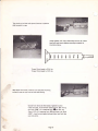
, TRACK ADJUSTMENT AND ALIGNMENT
4.
To work on track, lift rear of machine and set on secure
stand, about 4" to 8" off the floor. To make track adjustments:
1. Loosen rear idler wheel tie down rod (A). allowing the
idler wheels to turn freely as adjustments are being
made.
2. Break lock nuts (B) away from adjustment nuts (C) on
both sides of suspension, allowing you to move the idler
shaft and wheels forward and back for adjustment.
3. Correct track drop is 1-1/2" away from the slide frame
(D) to inside sliding part of track. Do not pull down on
track to get this measurement and make sure that track
is free of ice and snow or other weight. Correct tension
and alignment should result in an even drop on both
sides.
To check track alignment, start engine with machine on
stand and turn track over slowly . (Caution -do not run
track fast when checking alignment, and clear all tools\.___/
away from track and suspension areas ~ starting
engine.) After adjustments have been made, stop machine and shut off engine. Measure distance from rear
of suspension upri_ght (E) to rear of adjusting nut (C)
on both ~des. Measurements should be equal. If
there is misalignment, side of track closest to tunnel
must be tightened. If track is already very tight, then
adjusting nut on track side farthest from tunnel must be
loosened. Adjusting for drop and alignment, you should
wind up with correct track tension and alignment. Track
should be run after each adjustment to see if corrected.
When track adjustment is correct, tighten rear idler
tie-down rod, then tighten locking nut against adjusting
nut on both sides of suspension, being careful not to
move adjusting nut. After locking all nuts, start engine
and check adjustment once more.
DRIVE CHAIN ADJUSTMENT
A well-adjusted chain has 1/2" deflection (A) in travel
between the two chain case sprockets. Chain tension is adjusted by tightener bolt (B). To adjust chain tension, loosen
and back out lock nut (C). With an inch/lb. torque wrench,
torque. tightener bolt to 10 inch/lb., then back tightener bolt
out 1/2 turn~ Turn lock nut in and jam against chain case,
being careful not to further tighten bolt.
When refitting chain case cover, replace . lubricating oil.
Add oil through filler plug (D), with check plug (E) removed.
When oil level reaches check plug level, replace plug.
\
\.,______.-./
Page 23
COOLING SYSTEM
Your Brut snowmobile is equipped with an exclusive
· Brooten liquid-cooled, two:.Cycle engine. Your cooling system
requires an Ethylene Glycol-based coolant mixed at least
50-50' with water. Use more coolant for colder weather. If you
live in a climate where temperature drops to a -40°F. mix
coolant to match the temperature. Check coolant with an antifreeze hydrometer. To check coolant level, run machine
enough to warm up engine. Coolant level should be approximately 1-1/2" below sealing surface of tank. Also check
system periodically for loose clamps.
FUEL !'JIIXING RATIO
Mix 20 parts of gasoline to 1 part of oil (a 20:1 ratio),
which is 5 gallons ~f gas to 1 quart of oil. Too much oil will
cause plug fouling, smoking and excessive carbon formation .
Too little oil can cause engine overheating with resulting piston
seizure or engine. bearing failure.
LUBRICATION
I
\
Your Brut has two lubrication points. One is the chain
case which has an oil bath reservoir for the drive chain. Maintain oil level with No. 10 weight nondetergent oil. To check
correct oil level, make sure machine is on level surface. Loosen
or remove check plug at bottom of chain case. If oil does not
appear when removed, open filler plug at top of chain case and
add oil until oil appears at check hole.
There is a lube fitting on slide suspension frame near
front idler wheel. Use only Brut Track Suspension Lubricant,
which has a low melting point. This lubricant is not a su1;1Situte
for no-snow conditions and does not permit your Brut to be
run for distances without some moisture or snow for normal
slide rail suspension lubrication. Brutanza has available an
optional suspension wheel kit for marginal snow conditions.
MIXING INSTRUCTIONS
Never mix gasoline with oil in your snowmobile's fuel
tank! Use a clean container. Fill it about half full of gas. Add
the right amount of oil to fill the container with mixed fuel.
Shake the mix well, then add the remaining amount of gas to
fill the container with mixed fuel. When refueling your
snowmobile, use a funnel with a fine screen to prevent spilling
and entry of dirt and water into the tank. Always reshake the
fuel container if it's been sitting around for even a few hours
to prevent oil from settling out.
FUEL MIXTURE
Your Brooten engine is a two-cycle, or two-stroke
snowmobile engine which requires you to mix lubricating oil
with the gasoline. The carburetor draws this gas/oil mixture
into the crankcase for the engine to lubricate internal moving
parts.
/-
GASOLINE
Use a good grade of clean fresh gasoline. Don't use
gasoline that has been stored in containers for a long time,
since storage usually results in a gummy substance that can
plug carburetor jets.
OIL
Use a good grade of two-cycle engine oil , which states
on the label that it is blended for snowmobiles. If your spark
plugs are fouling a lot, there is a good chance that you are not
using a good oil for your Brooten engine.
Page 24