1
.OIDIIOIIIE
IIAnUAI
CHOKE LINKAGE ADJUSTMENT
28
STEERING ADJUSTMENT AND SKI ALIGNMENT
28
ENGINE TIMING
28
3
SERVICING DRIVEN CLUTCH
28
DR IVE BELT PREVENTIVE MAINTENANCE
8
SERVICING DRIVE CLUTCH
28
1973 BRUT SNOWMOBILE
10
SKAG REPLACEMENT
29
BRUT'S LIQUID COOLED ENGINE
10
HEADLIGHT REPLACEMENT
29
BRUT SPECIFICATIONS
11
HEADLIGHT ADJUSTMENT
29
ENGINE TIMING
11
TAILIGHT-BRAKE LIGHT REPLACEMENT
29
BRUT SERVICE TOOL USTING
BRAKE ADJUSTMENT
29
BRUT SNOWMOBILE CUTAWAY
DRIVE BELT REPLACEMENT
29
294 QUICK SERVICE CHART
SET UP PROCEDURE
2
TROUBLE SHOOTING THE TWO
CYCLE ENGINE
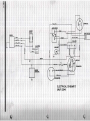
1972 LC44 ELECTRICAL SCHEMATIC
12
CLUTCH ALIGNMENT
30
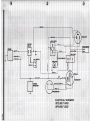
1973-74 LC29 ELECTRICAL SCHEMATIC
13
RIDE ADJUSTMENT
30
1973 LC44 1974502 ELEClRICAL SCHEMATIC
14
SPR ING TENSION
30
SUSPENSION
15
SHOCK TENSION
30
DRIVE SHAFT REMOVAL
15
DRIVEN CLUTCH ADJUSTMENT
30
I NVOLUTE DRIVE SPROCKET REMOVAL
16
TRACK ADJUSTMENT AND ALIGNMENT
31
CLUTCH REMOVAL
16
DRIVE CHAIN ADJUSTMENT
31
DRIVE INSTALLATION
16
COOLING SYSTEM
32
BRAKEINSTALLATMlM
17
LUBRICATION
32
SUSPENSION INSTALLATION
17
FUEL MIXTURE
32
ENGINE REMOVAL
18
GASOLINE
32
ENGINE DISASSEMBLY
20
OIL
32
ENGINE ASSEMBLY
22
FUEL MIXING RATIO
32
PISTON RING INSTALLATION
25
MIXING INSTRUCTIONS
32
THROTTLE LINKAGE ADAJSTMENT
28
DEALER WARRANTY CLAIM INFORMATION
34
LC 29 QUICK SERVICE CHART
1/ 2"
Clutch Offset
Center to Center of Clutch
Proper Belt
Point Settin
Fixed
Brutanza Belt # 13126- or # 13126·14
~ ...
.012" - .017"
3.5 mm or .138" B.T.D.C.
MUST BE COM PLETED AT FUll SPARK
T iming
ADVANCE
Pl ug Gap
.020
Carburetor Adjustment
High 1 turn
Idle Speed
Low ' · 1/8 turn
1500-2000 RPM
Standard B7ES NGK
Replacement N3 Or N3G Champion
Hard running BBES NGK o r N2G Champion
Spark Plug
,
BOLT TORQUE SPECI FICATIONS
NUT SIZE
5/ 8 Clutch
10 mm
12 mm
. ~E
']~
Ski Adjustment
14mm
Flywheel
. ' .r ••
~.
-.'
'·~
'.'
,
'r . . " , • •
.
.... _"... _""---".
"
_. -
TORQUE
35 ft .l bs.
60 in . Ibs.
18 ft . lbs .
25 ft . Ibs.
60 ft . Ibs.
1/4" toe out
Oil - use a B.I.A. endorsed oil w ith T,C.W. specs.
ST wi ll so state on the can. Mix according to oil manufacturers direct ions.
Gas - Use a good grade of leaded fu el from a station that moves a lot of gas (gasol ine that sets dormant can lose
up to 50% of the octane in a 30 day period.)
Page l
Una-ate the liquid cooled BRUT snowmobile. Be cautious
that the upholstery is not tom or the finish on the cowl
scratched.
2. Check all parts for shortages. If there should happen to be
a shortage on some ~ you must file a warranty claim
within 10 days to receiwe credit for any parts which you
use from your- own ~
3. Install springs in suspellsion, set suspension shock and
install suspension in c:ha!iIsis.
4. Align trade. Refer to Semce Manual page-;..&
"fl} i
5. Install skis and sb!eIiI. post and adjust toe out to
6. Check coolant IewL This
neck on surge 1ank.
7. Check chain
c:aIe
~ should
~".
be 1·1 W' below the
oil Ina and chain tension.
S. Check belt aIigi.ueilt. 'The offset should be W'.
9. Check brake and 1hrottIe cable for adjustment and
operation. Adjust if fF
y.
13. After engine starts, set the idle adjustment also the idle
speed.
14. Run engine a few minutes at slow RPM to clear out excess
fuel and oil. Shut engine off.
15. Install drive belt, raise rear of machine, check for clutch
operation and track alignment.
16. Check high low beam on head light also tail and brake
lights.
17. Set high speed adjustment on carburetor.
18. Machine should be cleaned up before delivery to cus·
tomer.
19. Be sure warranty registration is filed with in 10 days of
date of sale. Th is is a Federal Law on all motorized
vehicles. BRUTANZA ENGINEERING reserves the right
to reject all warranty on machines not registered within
proper time l
20. Steps 1 thru 19 should be repeated again after about 10
hours or 100 miles of driving.
10. Inspect choice .......IioIL
11. Install windshield.
1 2. Prepare to surt engine.. It is advisable to have a squ itt
bottle handy when SIaftiI. a new engine. Remove drive
belt, pour about one bIbIespoon of oil through the
carburetor intAlke of eKh cyfnder, pull the starter rope a
couple of times to distrhJle oil in engine. Give engine a
small amount of gas oil mixture from squirt bottle. Make
sure kill button and . .ition switI:h are on, pull choke out
and pull th~ If me engine does not start in one or
two pulls, add a little mere gas oil mix.
A couple of hours well spent on pre·delivery and a check up
can save you, the dealer, many hours'of work and many dollars
in the course of the winter.
It will also make for a very good
relationship with your customer.
Page 2
vinta IA. s SI?AR R~ G C0N Dfil oN agesnowmobi ~ tRelilil Cilve 1he ~ll:lg, cll eol< tlile h'@a bile.com
nge
, and1exam gehe firing AAobile.com
vintagesnowmoblle.com vi agesnowmobi
vintagesnowmobiF .com vintagesnowmobile.com . lH~N owmobile~com
vintages ;t;ble spa~1{ I 'g is . rYl vintagesnowmobile.irnere is 'h 0 ~uel ges ow obile.com
vintagesnowmobile.com vintagesnowmobi e. 0R the na kcase is cOflil r:lletel~ obile.com
flooded and fuel will not transfer.
vintages The spark
' plugiI is wet vintagesnowmobi e. T 9
k ' I . e l f I' d
blle.com
lie spar p ug simp y ou e or
vintagesno mobi e CO vintagesnowmobile the ne is some otmer defiC'ien'C~i obile.com
vintagesnowmobile.com vintagesnowmobil the ignition sya em 0 mob le.com
.
OR, there is flooding due to excesvintagesnowmobile.com vintagesnowmobi e ive uel
a es 0 mobile.com
vint ge 0 rno 'I r.
vintagesnowmobi
vinta B. s F.UE l! ~AI L!A ~ Il:, rIi Y vintagesnow obil Remove tb fuel line frOIT;) the car-bile.com
buretor.
vintagesnowmo
com vintagesnowmobil
VI 9 s owmobile.com
vintagesno ob !i .o vintagesnowmobil c. m
~nowmobile.com
•
Fuel will not,flow to
.
•
Check the:
.
'
vintages tHe carl)u retor • 0 vlntagesnowmobll. iVank vent gesnowmoblle.com
vintagesnowmo . .com vintagesnowmobile.r ~~:: ~/I~~r Yp e owmobile.com
vintagesnowmobile.com vintagesnowmobile.co Ruel li mes ana itti flg mobile.com
vintages w obi r.o
i tagesnowmobile c ;rt mer pum Qe nowmobile.com
vinta e·s Gif LiNDE COMPRESSION agesnow - obil Place our inger tigbtly ove~ obile.com
t e plug hole. CranK the engine.
vintagesnowmo i com vlntagesnowmobil .r.o 'i a es owmobile.com
lF
vintagesno
'mobi
.co vintagesnowmobile GO to ST AGE ITI,HCEONMPRESSIO c' EC .0
The pressure does not
vintages "pop' our f inger oft vintagesnowmobile r.O
I ag 0
obile.com
vintages the hole O Ile.com vintagesnowmobile.com vintagesnowmobile.com
vintagesnowmobile.com vintagesnowmobile.com vintagesnowmobile.com
.c
IS
0
o le.com
77
9
G
agesnow
0
iI .co
vintage
0
S
mobile.com
vintagesnc
vintagesnc
vintagesnc
vintagesnc
vintagesnc
vintag s
vintagesnc
vintagesnc
vintagesn
vintagesnc
vintagesnc
vintagesnc
•
vlntagesn
vintagesnc
vintagesnc
vintagesnc
vintagesnc
vintagesnc
vintagesnc
vintag
vintage
vintagesnc
snc
D.
TROUBLESHOOTING - CONTINUED
Connect the plug to its wire,
rest plug shell against head;
crank the engine.
THEN
SPARK TEST
IF
There is no spark or
the spark "tracks" up
the nose
Try the same test with a new
plug.
No spark with new plug
Go on to STAGE II, ELECTRICAL.
STAGE 1\
SPARK PLUG CONDITION
IF
The plug shows excessive
heat:
Check the firing end for unusual
deposits and conditions.
THEN
Check the carburetor for lean
settings and if OK, go on to
other checks for overheating.
BIis1ered Nose
Melted Electrodes
Aluminum or lead
"Beading"
"Bridged" Electrodes
The carburetor settings may be
too rich
OR, the air supply to the car·
buretor may be choked
OR, the exhaust system may be
overly restrictive.
Use a conventional spark plug hole
gauge. Crank the engine until the
gauge will go no higher.
Remove the cylinder and examine the:
Cylinder head
Piston
Piston rings
Cylinder
Check for proper tolerances.
The cylinder pressure
is above 150 p.s.i.•
Check for unauthorized modification.
SPARK GAP TEST
Connect a spark gap tester - start
the engine.
THEN
IF
The ignition system produces less than 7 mm of
spark
Proceed with the next step.
Page 4
TR OU BLESHOOTING - CON TI NU ED
D.
IGNITION TIM ING CHECK
Follow the normal ignition timing
prOC«fures using a dial gauge and
point checker.
THEN
IF
You f ind loose Of
improper wire connec-
Clean connections and reconnect
properly.
lions
The contact points do
not open and close
Clean until they do.
properly
When the points are
physically open and
you do not get a normal
point checker resistance
reading
The poinu may be "grounded" or
"open" permanently (replace or
repair).
OR, the primary coil is open or
the windings are not insulated
(replace).
THEN
IF
The ignition timing is
excessively advanced
The engine will run hot and maybe
detonate (adjust as necessary).
The timing is excessively
retarded
The engine will not produce no rmal honepower (adjust IS neces·
"'V).
E.
STROBE LIGHT TEST
l!'
THEN
A machine with centrifugal advance mechanism
does not go to fun
advance
Performance will be poor. (Re·
move the flywheel and clean and
lube the automatic advance.)
The strobe light indicates that the malks
"stray" from alignment 1/ 4" or mOle
Poor performance and overheating
will result (note any obvious
crankshaft deflection and go
on to STAGE III, CRANKSHAFT
DEFLECTION).
Q!!
there are random
flashes in addition
to normal ignition
Page 5
Start tile engine with a strobe
(tim ing) light connected and
watch the marks provided on the
flywheel and backing plate. Rev
the engine slowly through the
rpm range.
TROUBLESHOOTING - CONTINUE,D
STAGE III
Remove, disassemble and inspect
the carburetor.
IF
You find dirt or bits
of metal
The carburetor will cause engine
flooding (wash clean).
There is a flaw in
either diaphragm or
the check valve sheet
The carburetor may not deliver
enough fuel and the engine will
run hot or perhaps will not
start at all (replace damaged
parts).
The fuel inlet valve
(needle and seat) is
The fuel will not be controlled
and the engine will be flooded.
damaged
B.
The mounting flange
is warped
Air will leak into the intake
port and cause a lean mixture
(surface grind the flange).
MUFFLER INSPECTION
Remove the muffler.
IF
It appean to be
clogged with deposits
C.
The engine will not produce
normal horsepower and may over·
heat (clean out the muffler).
You can hear loose
metal pieces or
silencing material
when you shake the
muffler
The engine will not produce nor·
mal horsepower and may overheat
(replace or repair the muffler).
CRANKCASE PRESSURE CHECK
Seal the intake and exhaust ports
and connect a pressure checking
device. Pressurize the engine
to 10 p.s.i.
The air/fuel mixture will become
lean enough to be noticed as a
"hot" plug reading. The machine
will suffer from short plug life.
The pressure leaks at
a rate greater than
llb./min.
The air/fuel mixture may become
lean enough to cause preignition,
detonation, and perhaps melting
of the piston crown.
Page 6
CHECK
NOTE:
flection can be either
bearing freeplay (the
end will move up and
down without rotating
the crankshaft) or
crankshaft m isalignment (the end will
Remove the primary drive unit
and the magneto from the ends
of the crankshaft. With a
magnetic stand, mount the dial
gauge and check the deflection
on each end.
The crankshaft seals can be
stretched to the point that
an air leak will occur (this
will not be detected by a
stati c pressure test). The
engine will overheat due to
lean mixture.
AND/OR, the ignition contact
points can be opened at the
improper time. This will
cause overheating and poor
performance.
In either case, major engine
work is necessary.
Use appropriate instruments to
test the:
Condenser Capacity
Condenser Insulation
Secondary Coi I Resistance
Spark Plug Cap Resistance
There will be starting, plug
fouling, and performance problems caused by weak spark (or
no spark).
(Replace components as necessary ).
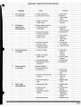
'C'nn'\A,rn DRIVE BE l!m eREVENTIVE MAINT ENANCE
n\A'II'Y\"I""il~
Symptoms
c. Rough or scratched
pulley surface
Excessive slippage caused by:
a. Insufficient pressure
on belt sides
Excessive horsepower
for belt and converter
Excessive oil on
pulley surfaces
d. Insufficient pre-load
on driven spring
e. Excessive operation
in low gear position
a. Excessive slippage
Improper belt angle
Considerable use, belt
wearing out
Excessive slippage in
driver pulley caused by:
a. Locked track
Converter not functioning
properly
c. Engine idle speed too
high
a. Idie speed too high
b. Incorrect belt or
belt length
c. Incorrect drive center
Align pulleys
Replace or
tighten engine
mount
c. Grind or polish
pulley(s)
a. Check driver
pulley for
smooth actuation
b. Consult dealer
c. Check bearing
seals and
clean pulley
surfaces
d. Consult 0 perator's Manual
e. Inspect converter
a. Check driver
pulley for
smooth
actuation
b. Grind or polish
pulley(s)
c. Consult dealer
d. Replace belt
a. Rotate track
by hand until
free
b. Repair or replace converter
c. Reduce engine
RPM
a. Reduce engine
RPM
b. See Operator's
Manual
c. See Operator's
Manual and
reduce center
distance
Replace bearing
Page 8
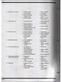
6.
Concave worn belt side(s)
a. Excessive ride-out
on driver pulley
b. Drive misalignment
c. Rough or scratched
pulley(s) surface
d. Excessive slippage
a. Repair or replace
driver pulley
b. Align pulleys
c. Gri nd or pol ish
pulleys
& Repair or replace
driver pulley
7.
Belt disintegration
a. Excessive belt speed
a. Reduce engine RP
at high speed
b. AI ign sheaves
b. Sheave misalignment
causing belt flip-over
c. Excessive slippage
causing heat build-up in belt
Excessive operation
in low gear position
9.
c. Inspect converter
d. Inspect converter
a. Pulley misalignment
b. Excessive belt speed
c. Excessi'le ride-out
on driver pu Iley
d. Incorrect belt
length
a. Align pulleys
b. Reduce engine RPM
c. Repair or replace
driver pulley
d. See Operator's
Manual
Belt edge cord broken
a. Pulley misalignment
b. Improper belt
installation
c. Engagement speed
too high
a. Align pulleys
b. See Operator's
Manual
c. Reduce engagement
speed
Flex cracks between cogs
a. Considerable use,
belt weari ng out
b. Bent pulley(s) flange
causing belt flutter
c. Excessive operation
in low gear position
d. Extremely low temperature
a. Replace belt
d. Warm up belt slowly
a. Improper belt
installation
b. Belt rubqing stationary
object
c. Idler bearing seized
a. See Operator's
Manu.al
b. Check drive
components
c. Replace bearing
a. Engagement RPM too
high
b. Belt hanging up in
bottom of driven pulley
c. Locked track
a. Reduce engagement
RPM
b. Belt too short;
replace
c. Rotate track by
hand until free
Sheared cogs, compression
section fractured or torn
b. Repair or replace
pulley
c. Inspect converter
p",,,,, 1 n
vint es ~f)JUS MEN
vi I omWN obile.com
vln e NtJ\Ji$ obile.com
vintagesnowmobile.com
vintagesnowmobile.com
vintagesnowmobile.com
,vintagesnowmobile.com
esnowmc
esnowmc
wmc
esnowmc
I gesnowmc
(ll ~~~~~~~~~~~.com Intagesnowmc
Inta
U .com vintagesnowmc
0 mO WHEE Il:S ina
RI Ei SHAftir I agesnowmobile.com i
snowmc
'5USR NSI6)N S IDE om vint ~RAGK~mobilU~:r: 5~NA L: ffi A ~ 6)RJME - BOeKE snowmc
vintage 0 moblle.com vintagesnowmobile.com Intagesnowmobile.com vln
snowmc
vintagesnowmobile.com vintagesnowmobile.com vintagesnowmobile.com vintagesn
vintagesnowmobile.com vintagesnowmobile.com vintagesnowmobile.com vintagesno
c
vintagesnowmobile.com vintagesnowmobile.com vintagesnowmobile.com vintagesnowmc
vintagesnowmobile.com vinta snowmobile.com vi ta
no mobile.com intagesnowmc
SUSPENSION
Remove suspension. To remove suspension remove the
four (4) 3/8" locking bolts mounting suspension to chassis.
Plug air bleed hole in gas cap, turn machine on to one side.
Then pull out suspension. 1974 also has locks on front
suspension lock bolts.
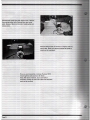
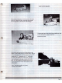
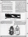
DRIVE SHAFT REMOVAL
To remove drive shaft, the chain case must be removed
and the suspension must be removed. On the left side of
the machine is a locking collar positioned on the spherical
bearing in the flangette. (Photo at right) Loosen allen
screw, turn collar opposite way it was installed. Note
punch mark in locking hole. Slide collar over shaft, then
push shaft into chain case hole and pull out bottom.
Chaincase assembly must be removed before drive shaft
can be removed. (Two photos below) Remove chain case
drive elements. Remove chain by remov ing snap ring on
upper sprocket and bolt on lower sprocket. Remove
chain tensioner by backing out tightener bolt.
INTERNAL DRIVE SPROCKET REMOVAL
With drive shaft removed, remove the track drive sprocket.
With long 1/4" punch, pound out 5/16" roll pin from
shaft. Drive sprocket should slide off.
ree (3) Phillips head screws holding bumper
and hood e rusion onto nosepan on left side of machine
only.
e 7/ 16" clutch bolt, then large nut on
ad clu tch pu lIer into threads of large
• earing on end of puller will press against
a and pull clutch, by tightening puller
ary on models equipped with
i e Clutch.
LATION
be on flangette side of shaft with
eccentric po 'on facin g tunnel before installation.
Before in aili ng chaincase, be sure snap ring is on
shaft.
machine lying on left side, fit track into
tunne . Then push driveshaft into chaincase hole
and hac
rough spherical bearing mounted on
the flangette. Holding drive sprockets as close to
center of tunnel as possible slide chaincase onto
drive shaft. Snug chaincase tightly up against tunnel.
Slide top sprocket spacer over spline and install
sproc ets and chain. Screw bolt in driveshaft to
hold chain sprocket on apd center track drive
sprockets.
Slip snap ring on top drive sprocket in chaincase to hold
it in position. Install chain tightener assembly and
tighten chain so there is 1/2" deflection in chain. Jam
locking nut on tightener bolt. Check "0" ring seal on
chaincase cover and install if O.K. Be careful not to
damage jackshaft seal when installing chaincase cover.
Go back to driveshaft inside tunnel and slide lock collar
into position next to flangette bearing. Turn collar lock
with punch and tighten with socket wrench.
Page 16
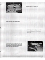
BRAKE INSTALLATION
Place inner brake puck in chaincase cover. Install brake
disc, then brake assembly. Make sure round end of
actuating pin is toward actuating lever. Adjust brake so
brake lights operates when brake is applied.
J
With track and driveshaft installed, you can now install
suspension. Raise machine rear approximately 3~'' off
ground on secure stand. Slide suspension into track. Line
up front two (2) mounting bolts, insert and tighten.
Slide a 2"x2" or 2"x4" block under track, positioned
just behind second set of front idler wheels. Drop rear of
machine down. Push down or up 6n machine rear while
holding rear suspension mounting shaft until shaft is in
line to insert mounting bolts. Tighten bolts and align
suspension. (See page 23 for track adjustment and
alignment.)
ENGI E RE OVAL
Loosen linkage swivel screws on choke and throttle on the
carb next to the coolant pu mp. Remove choke cable from
choke cable bracket. Remove throttle cable at throttle
lever next 0 handle ~i p.
Remove two (2) 1/4" nuts at upper steering bracket. Lift
steering post away from engine compartment.
Disconnect COl unit lead to engine. Disconnect the
two (2) yellow lighting wires and black ground wire
leading from stator unit. Disconnect spark plug leads.
Page 19
ENGIN E DISASSEMBLY
Remove the 1/2" carb nuts.
ext remove the 8mm exhaust manifold nuts and 8mm
bolts in crankcase holding on the muffler. Remove 6mm
nuts holding both coolant manifolds in place, then
remove manifold after disconnecting coolant bypass hose.
Remove the three (3) 8mm bolts holding water pump
mounting brackets to end cylinder, then remove water
pump and brackets. Remove motor mounts on top
and bottom of engine.
Remove 10mm cylinder nuts and slide cylinders off
pistons. With snap ring pliers remove piston pin snap
ring. Remove piston pin being careful not to apply
excessive side pressure to connecting rod .
Remove piston pin bearing and bearing spacers.
Page 20
Now you can disassemble crankcase. Remove 18/12
remaining 8mm bolts and two (2) 10mm
bolts. With plastic hammer, tap on one half of
crankcase, holding the other half. When case separates
shaft can be removed.
Page 21
£NGI NE ASSEMBLY
Page 22
Choose from three (3) thicknesses of gaskets to place
under seal plate. If micrometer measures from .091 and up,
use .2mm (.008"); if it measures from .081 to .091, use
.3mm (.012); if it measures from .080 and down, use .5mm
(.020"). Install correct gasket and seal plate, bend lock tabs
over plate bolts.
Sh p piston over connecting rod holding bearing and
spacer in place. Slide piston pin through piston, bearing
and spacers, then install remaining. snap ring. On 1973
models with "L" ring pistons, the "L" ring locator
pin mu st face intake port and on bottom ring the
locator pin must be between exhaust and transfer
port. On 1972 models with standard pistons, both
locator pins must be between the transfer and the
exhaust port.
PISTON RING INSTALLATION
Expand ring until it just slips over piston. Do not expand
any further than necessary to barely clear ring over piston.
Be sure ring is correctly positioned so ring notch slides into
ring locating pin correctly. With rings in place, set pistons
aside.
After pistons have been installed, bolt on cylinders
Position cylinders so intake port, or carb
side, is toward side of crankcase with impulse fittings.
Place wooden block under piston so it sits solid on
crankcase. With ring compressor over piston rings,
slide cylinder onto piston.
Caution: Ring ends will catch in transfer ports so you must
press them with your fingers. Do not force cylinders on!
When rings do not catch, cylinder will slide on with little
effort.
With cylinders in place, place inlet coolant manifold
on cylinders and torque 6mm nuts to 60 inch Ibs. Then
tighten four (4) 10mm nuts securely on base of cylinder.
Caution: Be sure coolant manifold is torqued in place
first to properly align cylinders. Place heads on cylinders
and install outlet coolant manifold on heads and torque
6mm manifold nuts to 60 inch Ibs. Now torque 8mm
head nuts to 17 ft. Ibs. using the following pattern:
6
•
(LC29) Coat breaker cam with thin coat of grease.
Connect timing equipment, light, buzzer or ohm
meter to white primary lead, adjust point gap to
get correct timing. Point gap should be between
.012 and .017.
Install dust cover next to rotor stator assembly with 6mm
screws. On 1972 models, spacer ring must be in place
before installing lower belt pulley. With ring in position,
install pulley with 6mm screws. Slide "v" belt over pulley
and install recoil and spacer ring (1972 only) on crankcase.
Slide outlet water pipe on manifold and torque 6mm
nuts to 60 inch I bs.
With brackets mounted on water pump, slide belt over
pump pulley and screw brackets onto cylinder with
three (3) 8mm bolts. Tighten belt with tightener bracket
until you reach 1/2" deflection in belt.
Install ~ter inlet hose and bypass hose, and tighten clamps.
Fit exhaust gasket on manifold and install muffler with
8mm nuts.
Install the two (2) carbs closest to clutch. Throttle bracket
fits under carb nearest clutch. The 1/4" spacer fits center
carb and carb closest to coolant pump.
Install two (2) front engine mounts with four (4) 10mm
bolts.
Set engine in chassis and install six (6) 8mm bolts in the two
(2) 7/16" bolts on front mounts. Set steering post in position
and tighten all bolts. Install third carb next to coolant pump.
Install throttle cable on cable bracket. Center bracket on
threads using adjusting jam nuts. Slide linkage rods through
choke swivels on the two (2) carbs colsest to magneto and
loop linkage rod around carb closest to clutch. Replace
swivel screw after looping linkage rod over swivel. Mount
choke cable on choke cable bracket and tighten securely.
Thread choke and throttle cables through linkage swivel and
tighten swivel screw.
:THROTTLE l!INKAGE ADJUSTMENT
'VU II '1;;0
°"'v.
Vlrltc.aE~srlo·\rd
Loosen linkage swivel screws on the two carburetors
closest to clutch. Squeezing the throttle, the Iinkage rod
should move freely inside swivels without activating the
throttle shafts on these two carbs.
Back out all carburetor idle speed screws away from carb
throttle shaft stops. This will synchronize all butterflies
in closed position. Grasp linkage rod and push it hard
enough so first earn butterfly closes completely. The other
two carbs should be closed also. When they are all closed,
continue to hold down rod and tighten swivel screws
securely. Move throttle lever to check synchronization of
all throttle shafts. If synchronized, turn idle speed screws
until they just touch shaft stops, then make an additional
3/4 turn on each screw. You must turn them more for
proper idle but this should be done with engine running.
To set correct idle speed of 1500 rpm, you must turn idle
screws on all carburetors exactly the same amount.
CHOKE LINKAGE ADJUSTMENT
Make choke adjustments the same as throttle so choke
butterflies are all closed when choke cable is pulled.
Then, when choke is pushed in, butterflies should open all
the way.
To set timing, disconnect red wire leading from ignition
points to ignition coil on cylinder next to magneto.
Connect one lead of an ohmmeter, timing light or
timing buzzer on connector leading from points.
Connect other
lead to grounding surface on engine. Insert an indicator
in spark plug hole nearest magneto.
Position stator plate in center of slots. (Note: It is best
to set correct. timing with stator in this position. But
if timing cannot be adjusted to point gap specs, then
position of stator must be changed.)
Adjust point gap so points open when
dial indicator reads 3.5mm or .138".
The cam must be in full advance position.
Check point gap with feeler gauge and make sure point
gap is within specs of .012" and .017". If not, stator
plate must be adjusted accordingly to set proper specs.
When timing is correct on magneto cylinder, next set
timing on cylinder next to clutch. Disconnect white
lead to coil. Adjust timing by changing point gap only.
If stator plate is moved, flywheel cylinder must be
retimed.
'nl'\\A,'py,
SERVICING DRIVEN CLUTCH
STEERING ADJUSTMENT AND SKI ALIGNMENT
Position handle bars so they face straight ahead. Adjust
either ski so it is also facing straight ahead. Adjust ski
by loosening jam nuts at both ends of tie rod as necessary
to align one ski. If you cannot align one ski exactly, you
may have to index steering arm at spindle. When handle
bars and one ski are ali!J1ed,measure distance from one ski
to other at points on front and rear ski spring saddles. There
should be 1/4" toe out, that is, front of skis are spread 1/4"
farther apart than rear. If you do not have correct toe out, ~="" __ ,~
loosen jam nuts on tie rod that has not been adjusted
and turn whichever way necessary to get 1/4" toe
out. When steering is adjusted, make sure all jam nuts
and other nuts and bolts are tight.
Position removed clutch with fixed face down. Rotate
moveable sheave approxi mately 35° clockwise and hold
steady. Press ramp down to clear key and rotate so key
holds ramp down. Remove snap ring, then remove ramp.
Hold firmly to prevent sudden spring release.
Clean and examine all parts. Replace if worn. Slide
moveable face onto hub, replace key. Engage spring
with anchor point in ramp and anchor point in
moveable face. Rotate movable face 1/2 turn or
0
180 counter clockwise after spring tension is taken
up. Push stationary ramp down on hub shaft and
lock under key. Replace snap ring. Release stationary
ramp to seat against snap ring.
SERVICING DRIVE CLUTCH
LC44 - The LC440 engine is equipped with capacitor
discharge ignition (COl) and timing is set in the factory
at 3.5mm BTDC. in fully advanced position. Timing
cannot be adjusted on this system and shou Id never
change.
LC29 - The LC294 engine is equipped with breaker point
magneto ignition system. Timing is factory set a 3.5mm
BTDC in fully advanced position.
Disassemble drive clutch by removing large nut
and installing clutch puller in clutch. Grab
moveable face with cover assembly firmly with
one hand and turn puller until clutch comes
off.
Holding moveable face of clutch in both hands and
puller facing floor, tap puller against a firm object.
It should separate from stationary hub. Remove puller
and clutch will come apart.
Inspect clutch arms to make sure they are not
sticking. Clean and examine all parts. Replace if worn.
Page 28
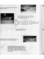
SKAG REPLACEMENT
The skag is a wear rod attached to each ski bottom to aid
in turning and prevent wear on actual ski blade. Check condition of skag wear often and replace skags when worn down
near ski. To replace, remove nut holding skag in place. With a
solid bar, bend s'kag outward until bolt is free from its ski hole.
Place a 1" piece of wood between skag and ski blade, just
behind front ski bolt. With hammer, tap on wooden block,
forcing skag forward until back pops out of slot. With new
skag, push front sloped end into front ski slot, with 1" wooden block positioned in front of rear skag bolt. While guiding
rear of skag toward rear skag hole by hand, tap on wooden
block to drive skag backwards. When skag bolts line up directly with holes, use pry bar to remove wooden block and skag
will snap into place. Then replace lock nuts on skag bolts.
HEADLIGHT REPLACEMENT
To replace headlight, start by removing wiring plug on
back of lens. With fingers, remove wire spring holding lens
down. Install new lens by first positioning it, then reinsert wire
spring and plug in electrical plug. Replace with dual element,
12-volt GE4454 bulb or equivalent.
HEADLIGHT ADJUSTMENT
Four headlight adjustment screws enable you to adjust
the beam, up, down and to either side. Adjustments should be
made for your particular driving condition. Caution: It is easy
to overdrive your headlight at night. Always use common
sense and a safe speed at night. Drive especially carefully on
unfamiliar land.
Page 29
BRAKE ADJUSTMENT
Remove cotter pin on castellated nut (G, page 23) and
tighten nut until puck presses against disc and there is about
3/4" brake handle play.
DRIVE BELT REPLACEMENT
Removal: Squeeze the brake so brake pressure will hold
the stationary sheave of the driven clutch. Grab moveable
sheave and rotate backwards, then pull belt down into driven
clutch "V". Lift and slide belt off stationary sheave of driven .
clutch. When loose from driven unit, remove from drive clutch.
Reminder - driven clutch should be pulled open completely.
Installation: Mount belt on drive clutch. Grab moveable face
of driven clutch with both hands on opposite sides of rim
diameter and turn moveable face backwards, then push to
compress the clutch spring. With clutch completely open,
push belt down between sheaves and slide belt over stationary
sheave.
CLUTCH ALIGNMENT
Offset from drive to driven clutch is 5/16" with salsbury/
salsbury and 1/ 2" with the salsbury /brutanza. Adjust by
add ing or subtracting washers on drive shaft under driven
clutch. To adjust parallel positioning (alignment) of drive and
dr iven clutches, loosen four (4) chaincase bolts and rotate
cha incase ~n slots until clutches are parallel. Then recheck
offset.
R IDE ADJUSTMENT
SPRING TENSION
I ncreas' ng or decreasing the spring tension by adjusting
the eye bol a
e front of the spring will alter the firmness of
the suspe ' 0 . hen adjusting spring tension, always have
'ct'on shocks completely released. Shock adjust·
come severe machine bottoming. Adjust the eye
. 12 02 inches of thread shows past the nut for a
bo rider . Increase the amount of thread showing
for a heav°er- pe son .
Page 30
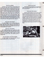
TRACK ADJUSTMENT AND ALIGNMENT
To work on track, lift rear of machine and set on secure
stand, about 4" to 8" off the floor. To make track adjustments:
1. Loosen rear idler wheel tie down rod (A), allowing the
idler wheels to turn freely as adjustments are being
made.
2.. Break lock nuts (B) away from adjustment nuts (C) on
both sides of suspension, allowing you to move the idler
shaft and wheels forward and back for adjustment.
3. Correct track drop is 1-1/2" away from the slide frame
(D) to inside sliding part of track. Do not pull down on
track to get this measurement and make sure that track
is free of ice and snow or other weight. Correct tension
and alignment should result in an even drop on both
sides.
4.
To check track' alignment, start engine with machine on
stand and turn track over slowly. (Caution - do not run
track fast when checking alignment, and clear all too ls
away from track and suspension areas before -starting
engine.) After adjustments have been made, stop machine and shut off engine. Measure distance from rear
of suspension upright (E) to rear of adjusting nut (C)
on both sides. Measurements should be equal. If
there is misalignment, side of track closest to tunnel
must be tightened. If track is already very tight, then
adjusting nut on track side farthest from tunnel must be
loosened. Adjusting for drop and alignment, you should
wind up with correct track tension and alignment. Track
should be run after each adjustment to see if corrected .
When track adjustment is correct, tighten rear idler
tie-down rod, then tighten locking nut against adjusting
nut on both sides of suspension, being careful not to
move adjusting nut. After locking all nuts, start engine
and check adjustment once more. On track drive lugs, periodically check point where lugs ride against rail. If one side shows
more wear than the other, check track alignment.
DR IVE CHAIN ADJUSTM ENT
A well-adjusted chain has ' l/2" deflection (A) in travel
between the two chain case sprockets. Chain tension is adjusted by tightener bolt (B). To adjust chain tension, loosen
and back out lock nut (C). With an inch/lb. torque wrench,
torque tightener bolt to 10 inch/lb., then back tightener bolt
Page 31
out 1/2 turn. Turn lock nut in and jam against chain ease,
being careful not to further tighten bolt.
When refitting chain case cover, replace lubricating oil.
Add oil through filler plug (0), with check plug (E) removed.
When oil level reaches check plug level, replace plug . .on 1972
models, plug (E) is drain plug only. When refitting chaincase
cover, add 1/2 cup oil through filler plug with drain plug in
place.
COOl!ING SYSTEM
,JII'I;;;.\'~"'I
Your Brut snowmobile is equipped with an exclusive Brooten
liquid-cooled. two-cyCle engine. Your cooling system requires
- an Ethylene Glycol-based anti-freeze and comes from the factory mixed 5(}50 with water. This mixture will protect to
-47 0 F. Periodically check coolant with anti-freeze hydrometer.
To check coolant level. run machine enough to warm up.
Coolant level should be approximately 1%" below top of tank.
Also check system periodically for loose clamps.
Your Brut has two lubrication points. One is the chain
case which has an oil bath reservoir for the drive chain. Maintain oil level with No_ 10 "'Ieight nondetergent oil. To check
correct oil level. make sure machine is on level surface. Loosen
or remove check plug at bottom of chain case. If oil does not
appear when removed. open filler plug at top of chain case and
add oil until oil appears at check hole.
(For 1973 models only. See page 23. DRIVE CHAIN
ADJUSTMENT. for 1972 model.)
There is a lube fitting on 51 ide suspension frame near
front idler wheel_ Use only Brut Track Suspension Lubricant,
which has a low mefting point. This lubricant is not a substitute
for no-snow conditions and does not permit your Brut to be
run for distances without some moisture or snow for normal
slide rail suspension lubrication. Brutanza has available an
optional suspension Wheel kit for marginal snow conditions.
FUEL MIXING RATIO
Mix 20 parts of gasoline to 1 part of oil (a 20: 1 ratio),
which is 5 gallons of gas to 1 quart of oil. Too much oil will
cause plug fouling, smoking and excessive carbon formation.
Too little oil can cause engine overheating with resulting piston
seizure or engine bearing failure.
MIXING INSTRUCTIONS
Never mix gasoline with oil in your snowmobile's fuel
tank! Use a clean container. Fill it about half full of gas. Add
oil and shake the mix well. Then add the remaining amount of
gas to fill the contaiRer with mixed fuel. When refueling your
snowmobile, use a funnel with a fine screen to prevent spilling
and entry of dirt and water into the tank. Always reshake the
fuel container if it's been sitting around for even a few hours
to prevent oil from settling out of gasoline.
FUEL MIXTURE
Your Brooten engine is a two-cycle, or two-stroke
snowmobile engine which requires you to mix lubricating oil
with the gasoline. The carburetor draws this gas/oil mixture
into the crankcase for the engine to lubricate internal moving
parts.
Page 32
ing a company gives out just to be
eed back we get to check on the
desperately need the cooperation of
o keep the BRUT updated and
chance on getting the claim rejected. No claim has been
rejected yet for this reason, however if it continues to be a
problem, there will be no other choice but to do so.
GROUP CLAIMS
In
warranty
filing clai
filled out
repa ir. If
are going to get tougher on the
a e been very lax in the past as to
is year the w arranty claims must be
umed in wi thin 10 days of date of
complied with, you are taking a
There will be times this year when we will use a group
claim. On any group claim, there w ill be a bulletin issued with
a group claim number. If there is no group claim number
assigned, refer to samples. Use Regular Warranty Procedure for
each unit.
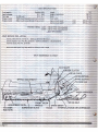
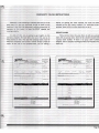
RNOIN • • RING INC.
,.•.31.
~1~t~:O:"t· f~'::=:~2~'~'''''uou
WARRANTY AllOWANCE REQUEST
HOLD ALL PARTS 60 DAYS AFTER MAILING CLAIM
~
WARRANTV CLAIM
434 :sJ
. 'M'~~:::;;:-""""::" "~:'~:~"~'::"~:::'~'~:~~'~:'
:~':, ]
Dealer
ilarne
- -
---- -
1- 1/1- 74
-
Address
--- ----
r:"I"A~IOf'j
DAtI:
21505-11
21518-:10
24704-12
24200-20
:'Jeight
SOOe
~WrT'ODlle.c:or
5/64" X 5/16 tt Roll Pin
1/4" X 20 UNC X 1/4" Pan Head Screw
=Three grams each weight.
Yellow 5 I/,2 coil .175 wire sprinP-: 3 1/2" to 3 3/4" Length
rrtJ'ee (3) of each of above
21510--10
Pert
1
1
1
1
3
'21300-14
21SOC=..r-ll
21518-- 10
24704--a12
24200- 21
24250-14
~''eight
SOOe
5/64" X 5/16" Roll Pin
1/4" X 20 unc X 1/2" Pan Head Scret~r
1/4" X .026 X 1/2" OD 'Plat i.rasher
. 'Ihree (3) of each of above = 6 1/2 gra"llS per weight
2151~1l
Orange 5 coil .192 "{lure spring 3" to 3 1/4" Length
Same as u=44 with exception each t"reight to have four (4) 24250-14
1/4 n X .026 X 1/2" on Flat Hasher. TP..is will equal 7 grams per lIJetght.
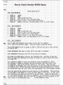
This clutch should be set to engage at 3800 to 4000 RPM and have a shift pattern
of 7500 to 7700.
Higher
~
Lo'~r engap}~ite!lt
will mean a higher PR'·1 at the start of movement. _,.. ..
""1 .....
will mean lower RPf1 at the start of movement.
The l~h of spr1ng mainly controls the engagement BP~1. The size of wire and
number of coils will determine the amount of ~Teight you need to shift the clutch
at a given ~-!.
Note pasit10n of IIm'ks on cover and stationary before disassembli.l1p-" clutch.
Note ~-osltlon of marks on !!lOveable face and stationary face ~rhen cover is not
yet a.esed:)led. r:h1s 1s the neutral position of the spring. Hhen the cover
is placed on tt~ moveable face, note the position of the cover wark in relation to
the Iroveat1e ~.rk. Eefore comnressIDp- spring and installing assembly nut, rotate
the clutch rover back arrl forth notirur the anproximate1y 1/2" free movement possiblE
Leave the cover in the counterc1ockl~ise position of this movement. This positions
the ~ pads of the IroveabJ.e 2!!8.inst the helix raI'l1Ps of the cover. At this point,
note the I!2-Tic en the cover and the Inarl{ on the stationary. These two marks must
be in tbis oosl tion a.-rter the clutch 1s assembled. If
increase of approximately
100 sP..L~ Rf!I is desired, move the cover mark an additional 1/2" clockwise of the
static point of the stationary marie.
DO NOT EXCEED 1/2 INCH.
an
DRIVE CLtJrCH SET UP
is desired ~ move the cover mark an additional
DO NOT EXCEED
,.. .:ire and. amount o.f coils will determine the amount of
rotat ing the cover a given distance.
100
~~~.!)I~~
::~. ....
-:-- ~_
_
!,PH
s atic point of the stationary m.ar!{ .
AJ·¥
PFESSUP~
BE PUT ON THE SPHING BY ROTATING!
be thrown off.
3.
shaft not letting clutc.h shift into hi$?;h gear.
4.
~~t
5.
ramr towers on moveable and prevent return to neutral.
,. to the point 't'lhere considerable damage may result.
SCre'tl-TS In Arms
on each arm HIll lower t he shift ra.np:e R'Pr~ by 50 --,."'""",.,..,,.,.,
(l) Hasher will raise the shift range by 50 _. 200 RP~/f.
. ashers "'rill not change the e~agement RP~·~ .
- J
~
--
~her
The main reason for this is to insure that
The screws on the 'tJTeip:ht arm
. locktite or punched in to insure they they do not come out.
u.J
ON CLUI'CH.
s:ay in a proper position.
___
~
seize or lock up for any l.' eas.()n . t.he '<~ 1 u teh shou1rl b e di smantled
lVe~ en the a.r"m..~ .
rutanza clutch on the LC 29 Brut it is
the driven clutch at 15# pull. This
~~~~u ished by using a 7 coil spring & wrapping
easure the pull exactly follow the
se
e ( engine) clutch bolt
between sheaves on driven
e bolt so the sheaves can rotate
not to jam thr~ads into shaft)
1 vise grip pliers.
Clamp a 24" piece
outer lip of the driven clutch.
as close to the engine head as
re pointing to the rear of machine.)
the end of your piece of wire.
(you
se a fish scale that reads to aprox.
al e to wire.
rear of the clutch. Pull on the
up the moveable sheave.
{move it
off the pressure easy so you do
eable sheave to hard.
:~ad1Dg _~~
-
°th one hand, the scale in the other
e scale slowly watching the scale
a reading when the sheave first moves}
ed from 3/8" to !Z" let the pressure
e_ slowly until the sheave starts
r O inal position. Take your next
~ _ ~~e starts to move.
Do this several
- . 2 readings each time.
You should
e pull of 18 - 19 lbs. and on
~~
O u,g of 11.5 - 14 lbs. or an average
ease of lSlbs.