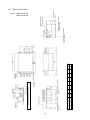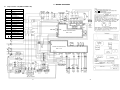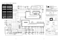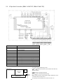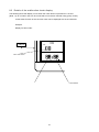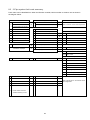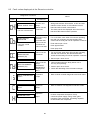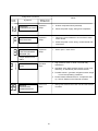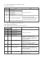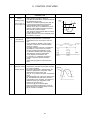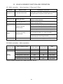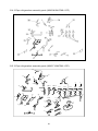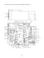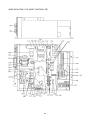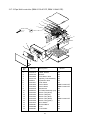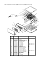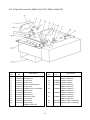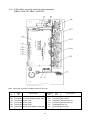
1
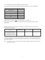
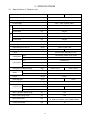
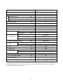
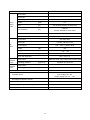
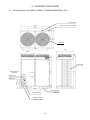
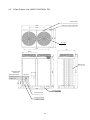
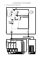
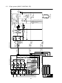
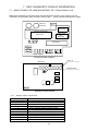
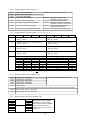
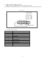
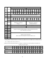
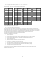
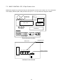
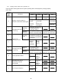
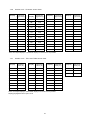
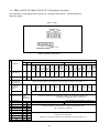
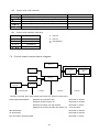
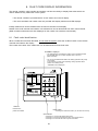
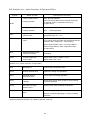
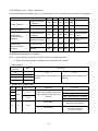
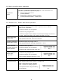
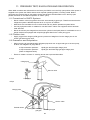
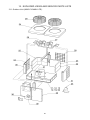
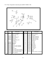
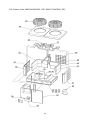
FILE NO. A90-0030
SERVICE MANUAL
AIR-CONDITIONER
2-PIPE SUPER MULTI, COOLING ONLY
Outdoor Unit
Multi Controller
MAR-C104M8-1-PE
RBM-Y1034C-PE (3-way)
RBM-Y1044C-PE (4-way)
2-PIPE SUPER MULTI, HEAT PUMP
Outdoor Unit
Multi Controller
MAR-M104HTM8-1-PE
RBM-Y1034-1-PE (3-way)
RBM-Y1044-1-PE (4-way)
3-PIPE SUPER MULTI, HEAT PUMP WITH
SIMULTANEOUS HEATING AND COOLING
Outdoor Unit
Multi Controller
MAR-F104HTM8-1-PE
RBM-Y1034F-PE (3-way)
RBM-Y1044F-PE (4-way)
1
Printed in UK December 2000
CONTENTS
1.
SUPER MULTI SYSTEM BASIC COMPONENTS ....................................................................................4
2.
OUTLINE OF CONTROL SYSTEM...........................................................................................................6
3.
SPECIFICATIONS .....................................................................................................................................8
4.
CONSTRUCTION VIEWS .......................................................................................................................15
5.
WIRING DIAGRAMS ...............................................................................................................................19
6.
REFRIGERANT CYCLE DIAGRAMS ......................................................................................................28
7.
SELF DIAGNOSTIC DISPLAY INFORMATION ......................................................................................31
8.
FAULT CODE DISPLAY INFORMATION.................................................................................................46
9.
CONTROL FEATURES ...........................................................................................................................53
10. VALVE & SENSOR FUNCTION AND OPERATION ................................................................................55
11. PRESSURE TEST, EVACUATION AND DEHYDRATION .......................................................................59
12. ADDITIONAL REFRIGERANT.................................................................................................................60
13. EXPLODED VIEWS AND SERVICE PARTS LISTS ...............................................................................61
SUMMARY
The units referred to within this manual conform with the protection requirements of Directives
89/336/EEC Electromagnetic Compatibility and 73/23/EEC Low voltage.
Operating conditions of the unit are as follows:
Outdoor temperature
Room Temperature
Room humidity
Note 1:
Note 2:
Note 3:
Note 4:
Note 5:
Note 6:
Note 7:
-5
-10
18
15
43°C
21°C
32°C
29°C
Cooling
Heating (MAR-M104HTM8-1-PE, MAR-F104HTM8-1-PE)
Cooling
Heating (MAR-M104HTM8-1-PE, MAR-F104HTM8-1-PE)
< 80%
Cooling
Cooling capacity is rated at the following temperature conditions:
Indoor air inlet temperature 27°C DB, 19°C WB.
Outdoor air inlet temperature 35°C DB.
Heating capacity is rated at the following temperature conditions:
Indoor air inlet temperature 20°C DB.
Outdoor air inlet temperature 7°C DB, 6°C WB.
For details on the Outdoor unit installation, the Indoor units or Remote Controllers refer to
the relevant literature. i.e. Installation instructions supplied with the units or Service
manuals relevant to the indoor units.
Operatives handling refrigerants must be suitably qualified in accordance with local and
national codes of practice and statutory requirements.
Legislation may regulate the removal of waste refrigerant from the systems. We advise
awareness of any regulations and duty of care. Waste refrigerant must NEVER be discharged to
atmosphere.
Electrical work should be in accordance with all relevant codes of practice and should be
carried out by suitably qualified personnel.
Metric / Imperial pipe conversion.
Diameter (mm)
Nominal diameter (inch)
Note 8:
~
~
~
~
6.4
1 /4
9.5
3/8
12.7
1 /2
15.9
5 /8
19.0
3 /4
22.0
7 /8
28.6
1 1 /8
Within this manual, O/D = Outdoor unit, M/C = Multi controller, I/D = Indoor unit,
R/C = Remote controller, D.O.L. = Direct on-line compressor.
3
1. SUPER MULTI SYSTEM BASIC COMPONENTS
1.1 2-Pipe Heat Pump.
This system allows separate operation of each indoor unit in heating or cooling.
Heating operation has priority over cooling. In the event of an indoor unit requesting cooling operation when
another is in heating mode, "STANDBY" will be displayed on the remote controller.
2-Pipe
Outdoor unit
T-Pieces
Multi controller
2 pipes
OFF
Indoor units
OFF
Remote controller
2 pipes
1.2 3-Pipe Heat Pump with simultaneous heating and cooling.
This system allows separate operation of each indoor unit in either heating or cooling simultaneously.
3-Pipe
Outdoor unit
Indoor unit remote controller requesting cooling
Cooling operation
T-Pieces
Indoor unit remote controller requesting heating
Multi controller
Heating operation
3 pipes
Indoor units
Remote controller
2 pipes
4
1.3 2-Pipe Cooling only.
This system allows operation of each indoor unit in cooling.
2-Pipe
Outdoor unit
T-Pieces
Multi controller
2 pipes
OFF
Indoor units
OFF
Remote controller
2 pipes
Indoor unit remote controller requesting cooling
Cooling operation
5
2. OUTLINE OF CONTROL SYSTEM
The refrigerant and electrical systems of the Super multi air conditioner are controlled by the Multi controller
and the Outdoor unit microprocessors.
All RAV Heat Pump, R407C, 4 series Indoor units are compatible with the Super multi system. i.e. 1 ~ 5 HP.
For system operation, initially the microprocessor in each Indoor unit calculates the difference between the
current room temperature (TA) and the requested temperature which has been set on the Remote controller.
A demand signal is determined and transmitted to the Multi controller microprocessor in the form of
operation commands. (i.e. ON / OFF, cooling or heating (M104-1 and F104-1 only) operation mode,
operation demand frequency).
The Multi controller microprocessor receives operation commands from all Indoor units connected,
calculates the accumulative operation command and transmits this information to the Outdoor unit Interface
microprocessor.
The Interface microprocessor calculates the capacity required for heating (M104-1 and F104-1 only) or
cooling and determines the operation mode of the Outdoor unit and the actual frequency of the compressor.
2.1 Control system diagram.
Outdoor unit
Indoor unit 1 – A
Multi controller 1
Protection unit
Fan
Capacity rank
setting switch
Comp. sensor
Temp. sensor
Temp. sensor
Pulse modulating
valve
Pulse modulating
valve
Temp. sensor (TA)
Drain Pump
Indoor unit microprocessor
Remote
controller
1-B
Multi controller
microprocessor
Interface microprocessor
Display LED
D.O.L.
compressor
2-way valve
(3-Pipe ONLY)
Display LED
2-way valve
1-C
Fan
1-D
4-way valve
For Heat Pump models only
2-A
Multi controller 2
2-B
Inverter
compressor
Multi controller
microprocessor
2-C
Inverter
microprocessor
2-D
Protection
unit
6
Inverter
Power
supply
2.2 Combination of Multi Controllers and Indoor Units.
Each Indoor unit is allocated a code number according to its capacity rank. Refer to the table below.
Capacity Rank of Indoor unit
Code No.
No connection
0
10
2
13
3
16
4
26
6
36
8
46
10
Example: Indoor unit model RAV-364UH-PE, Capacity Rank = 36, Code No. = 8.
(Each Indoor unit Code No. is registered by the capacity rank setting switches on the Multi controller
control board).
Multiple Indoor units may be connected to each Outdoor unit, providing the total Indoor code does not
exceed the limits shown below.
Outdoor Unit
Maximum No. of
Connected Units
Minimum Code No.
Maximum Code No.
8
2
27
10HP 2-PIPE (MAR-C104M8-1-PE)
10HP 2-PIPE (MAR-M104HTM8-1-PE)
10HP 3-PIPE (MAR-F104HTM8-1-PE)
The option is available to use a 3-Way Multi controller (for 3 Indoor units), or a 4-Way Multi controller (for 4
Indoor units). If more than 4 Indoor units are required for an Outdoor unit, 2 multi controllers should be used
with T-Piece connections.
Note:
It is possible to connect indoor units with a total capacity exceeding the capacity of the outdoor unit
by a maximum of 35%.
7
3. SPECIFICATIONS
3.1 Specification of Outdoor unit.
MAR-M104HTM8-1-PE
Model Name
Cooling capacity
(kW)
25.0 (28.0)
Heating capacity
(kW)
28.0 (31.5)
Cooling
Power supply
Heating
MAR-F104HTM8-1-PE
380 – 415V, 3-phase, 50Hz
Operating current
(A)
17.4 (19.1)
Power consumption
(W)
11,800 (12,800)
Power factor
(%)
98 (97)
Operating current
(A)
17.7 (15.5)
Power consumption
(W)
11,800 (10,500)
Power factor
(%)
96 (98)
Starting current
(A)
60
Starting method
Direct
Dimensions (H x W x D)
(mm)
Net weight
(kg)
1,530 x 1,290 x 834
346
Colour
Compressor
359
Bronze white (Munsell 6Y7.5/1)
Type
Motor output
Hermetically sealed (Twin scroll)
(kW)
7.5
Fan
Compressor
Motor output
(kW)
Air flow volume
(m /hr)
Refrigerant (charged weight)
Noise
Propeller fan
0.15 x 2
3
(kg)
10,000
R407C (16.0)
R407C (19.0)
Sound Power Level (SWL) (dB(A))
70
Sound Pressure Level (SPL) (dB(A))
63
Liquid
(mm)
Discharge gas
(mm)
Suction gas
(mm)
ø15.9
–
ø19.0
ø28.6
Liquid
Flare connection
Coupler style Discharge gas
–
Suction gas
Flare connection
Brazing connection
Max. equivalent piping length
(m)
120
Max. actual piping length
(m)
100
Max. piping head
(m)
50: When the outdoor unit is installed above.
20: When the outdoor unit is installed below.
Crank case heater
(W)
74
8
Model Name
Cooling capacity
MAR-C104M8-1-PE
(kW)
Cooling
Power supply
25.0 (28.0)
380 – 415V, 3-phase, 50Hz
Operating current
(A)
17.4 (19.1)
Power consumption
(W)
11,800 (12,800)
Power factor
(%)
98 (97)
Starting current
(A)
60
Direct
Starting method
Dimensions (H x W x D)
(mm)
Net weight
(kg)
Type
Motor output
Hermetically sealed (Twin scroll)
(kW)
Fan
Fan assembly
7.5
Propeller fan
Motor output
(kW)
0.15 x 2
Air flow volume
(m3/hr)
10,000
Refrigerant (charged weight)
Noise
324
Bronze white (Munsell 6Y7.5/1)
Colour
Compressor
1,530 x 1,290 x 834
(kg)
R407C (9.0)
(dB(A))
70
Sound Pressure Level (SPL) (dB(A))
60
Sound Power Level (SWL)
Liquid
(mm)
ø15.9
Suction gas
(mm)
ø28.6
Liquid
Coupler style
Flare connection
Suction gas
Brazing connection
Max. equivalent piping length
(m)
120
Max. actual piping length
(m)
100
Max. piping head
(m)
50: When the outdoor unit is installed above.
20: When the outdoor unit is installed below.
Crank case heater
(W)
74
The specification shown in ( ) denotes operation with the maximum capacity of indoor units connected
(i.e. 135% capacity of the outdoor unit).
9
3.2 Specifications of Outdoor unit Refrigerant Cycle Parts.
MAR-M104HTM8-1-PE
Model Name
Model name
Compressor
motor
MG1300CW-20
Motor type
3-phase induction motor
Power supply
380 – 415V, 3-phase, 50Hz
Output
(kW)
Pole
(P)
Coil resistance
(Ω)
7.5
2/2 (Inverter side/Non-inverter side)
1.49/2.51
(Inverter side/Non-inverter side)
Compressor oil name
Amount of oil
NISSEKI RB68AF
(cc)
7,000
Model name
Fan
motor
STF-200-150C
Motor type
1-phase, induction motor
Power supply
220 – 240V, 1-phase, 50Hz
Output
(W)
150
Supply current
(A)
1.12 ~ 1.44
Pole
(P)
6
Inner over-load relay
High
pressure
switch
Low
pressure
switch
MAR-F104HTM8-1-PE
OFF: 115 ± 5°C
Model name
Operating pressure
20PS-B (Inverter side), 20PS-G (Non-inverter side)
(kgf/cm G)
Operation 30, Reset 23
2
Model name
Operating pressure
20PS-1
(kgf/cm G)
2
4-way valve
Operation 0.25, Reset 1.5
CHV-0712, Coil AC240V
Compressor case heater
AC 240V, 74W
Model name: NTP-Q250TF-2
Pressure sensor
Input voltage: DC 12V
Output voltage: DC 0.5 – 4.5V
Discharge temperature sensor
At 25°C = 50kΩ, 50°C = 17.9kΩ, 100°C = 3.35kΩ
Suction temperature sensor
At 0°C = 32.8kΩ, 25°C = 10kΩ, 50°C = 3.6kΩ
Outdoor air temperature sensor
At 0°C = 32.8kΩ, 25°C = 10kΩ, 50°C = 3.6kΩ
EV18RC2, Coil DC 12V
Pulse modulating valve (For bypass)
Pulse modulating valve
–
2-way valve
NEV202DXF, Coil AC 240V
2-way valve
–
10
EV23RC8, Coil DC
RP100-03, Coil AC
Model Name
MAR-C104M8-1-PE
MG1300CW-20
Model name
3-phase induction motor
Motor type
380 – 415V, 3-phase, 50Hz
Power supply
Compressor
motor
Output
(kW)
Pole
(P)
Coil resistance
(Ω)
7.5
2/2 (Inverter side/Non-inverter side)
1.49/2.51
(Inverter side/Non-inverter side)
Compressor oil name
Amount of oil
NISSEKI RB68AF
(cc)
7,000
STF-200-150C
Model name
1-phase, induction motor
Motor type
Fan
motor
220 – 240V, 1-phase, 50Hz
Power supply
Output
(W)
150
Supply current
(A)
1.12 ~ 1.44
Pole
(P)
6
OFF: 115 ± 5˚C
Inner over-load relay
High
pressure
switch
Low
pressure
switch
Model name
Operating pressure
20PS-B (Inverter side), 20PS-G (Non-inverter side)
(kgf/cm2G)
20PS-1
Model name
Operating pressure
Operation 30, Reset 23
(kgf/cm2G)
Compressor case heater
Operation 0.25, Reset 1.5
AC 240V, 74W
Model name: NTP-Q250TF-2
Input voltage: DC 12V
Output voltage: DC 0.5 – 4.5V
Pressure sensor
At 25˚C = 50kΩ, 50˚C = 17.9kΩ, 100˚C = 3.35kΩ
Discharge temperature sensor
At 0˚C = 32.8kΩ, 25˚C = 10kΩ, 50˚C = 3.6kΩ
Suction temperature sensor
EV18RC2, Coil DC 12V
Pulse modulating valve (For bypass)
NEV202DXF, Coil AC 240V
2-way valve
11
3.3 Specifications of Outdoor unit Inverter Assembly Parts.
MAR-M104HTM8-1-PE MAR-F104HTM8-1-PE
Model Name
Power supply
380 – 415V, 3-phase, 50Hz
Output voltage at operating frequency of 60Hz
AC 266V
IGBT
MG50Q6ES11
Relay
LY1F (AC 240V)
Fan motor running capacitor
EAG45M605UF1, 6µF450V
Diode
SR130G-160
AC noise filter
ZSG2208-02, 8A, 250V
DC noise filter
LF215AV, 15A, 716V
Power supply rectifier capacitor
LNT2G222KSMCTF, 2200µF/400V
Fuse
20A
Electronic starter
912X25E101YV20
Reactor
CH-26-T, 6.2mH, 18A
Fan motor relay
G2R217PV
Control relay
G4U-112P
Magnetic contactor for compressor (Inverter side)
13A
Magnetic contactor for compressor
15A
(Non-inverter side)
Transformer (Inverter)
FT70
Transformer (Interface)
FT69
Power supply terminal plate
AC600V, 60A
PC board (Inverter)
PC board assembly (Interface)
MCC-1251 (INV-M-E)
MCC-1251 (INV-F-E)
MCC-1211
MCC-1223
PC board (Gate)
MCC-1252
Cooling fan
–
12
3650EXV-5, 220-240V
MAR-C104M8-1-PE
Model Name
Power supply
380 – 415V, 3-phase, 50Hz
Output voltage at operating frequency of 60Hz
AC 266V
IGBT
MG50Q6ES11
Relay
LY1F (AC 240V)
Fan motor running capacitor
EAG45M605UF1, 6µF450V
Diode
SR130G-160
AC noise filter
ZSG2208-02, 8A, 250V
DC noise filter
LF215AV, 15A, 716V
Power supply rectifier capacitor
LNT2G222KSMCTF, 2200µF/400V
Fuse
20A
Electronic starter
912X25E101YV20
Reactor
CH-26-T, 6.2mH, 18A
Fan motor relay
G2R217PV
Control relay
G4U-112P
Magnetic contactor for compressor (Inverter side)
13A
Magnetic contactor for compressor
15A
(Non-inverter side)
Transformer (Inverter)
FT70
Transformer (Interface)
FT69
Power supply terminal plate
AC600V, 60A
PC board (Inverter)
MCC-1251 (INV-M-E)
PC board assembly (Interface)
MCC-1211
PC board (Gate)
MCC-1252
13
3.4 Specification of 2-Pipe Multi Controller Parts.
RBM-Y1034C-PE
RBM-Y1034-1-PE
Model Name
Pulse modulating valve
RBM-Y1044C-PE
RBM-Y1044-1-PE
EV23RC7, Coil DC 12V
Temperature sensor
At 0°C = 32.8kΩ, 25°C = 10kΩ, 50°C = 3.6kΩ
Float switch
FS-085-0031
Power supply transformer
Model name
1401008301
Specification
Primary side:AC240V, Secondary side:AC12V
Relay (PC board)
G2R-117P, Coil DC 12V
10.4 W/m
Heater
50W
Thermal fuse for heater
65W
Cut out at 139°C
Heater fuse
T1A
3.5 Specification of 3-Pipe Multi Controller Parts.
Model Name
RBM-Y1034F-PE
Pulse modulating valve
EV23RC7, Coil DC 12V
Temperature sensor
At 0°C = 32.8kΩ, 25°C = 10kΩ, 50°C = 3.6kΩ
Float switch
Power supply transformer
RBM-Y1044F-PE
FS-085-0031
Model name
1401008301
Specification
Primary side:AC240V, Secondary side:AC12V
Relay (PC board)
G2R-117P, Coil DC 12V
10.4 W/m
Heater
50W
Thermal fuse for heater
65W
Cut out at 139°C
Heater fuse
T1A
Discharge gas side 2-way valve
RP100-03, Coil AC240V
Suction gas side 2-way valve
REV-1506DXFQ6, Coil AC240V
2-way valve
NEV202DXF-AC240V
2-way valve
NEV603DXF-AC240V
14
4. CONSTRUCTION VIEWS
4.1 2-Pipe Outdoor Unit (MAR-C104M8-1-PE/MAR-M104HTM8-1-PE).
Rear air inlet.
1290
650
4 slots (15 x 20) for fixing bolts.
➤
790
834
➤
➤
Air outlet.
1100
750
98
120
Ø 610
Side air inlet.
1212
1410
➤
Refrigerant pipe
connection.
140 65
Liquid Ø 15.9
➤
Gas Ø 28.6
➤
100
335
➤
500
➤
365
➤
2 x Fork lift slots.
(150 x 60)
Piping knockout.
Wiring knockouts.
1 x Ø25, 2 x Ø20
15
4.2 3-Pipe Outdoor Unit (MAR-F104HTM8-1-PE).
Rear air inlet.
4 slots (15 x 20) for fixing bolts.
1290
650
➤
790
834
➤
➤
Air outlet.
1100
750
98
120
Ø 610
Side air inlet.
Suction gas Ø 28.6
Discharge gas Ø 19.0
Liquid Ø 15.9
1212
1410
➤
Refrigerant pipe
connection.
140 65 65
➤
➤
➤
500
100
335
➤
➤
365
➤
2 x Fork lift slots.
(150 x 60)
Piping knockout.
Wiring knockouts.
1 x Ø25, 2 x Ø20
16
100
G
A
440
540
440
540
B
260
350
260
350
C
60
90
60
90
D
90
90
90
90
Refrigerant connection (brazing)
Liquid side Ø 15.9
MODEL
RBM-Y1034-1-PE
RBM-Y1044-1-PE
RBM-Y1034C-PE
RBM-Y1044C-PE
Outdoor Unit
Wiring Knockout
(1x20mm)
Reset switch
30 46
E
90
90
90
90
F
--90
--90
20
G
115
205
115
205
180
16.5
19.5
16.5
19.5
Weight kg
440
490
530
150
2-key slots for
hanging bolts
(each side)
20
Electrical parts box
230
45
B
20
Refrigerant pipe
connection (brazing)
Liquid side Ø 12.7
C
D
A
F
Refrigerant pipe
connection (brazing)
Gas side Ø 19
E
Indoor unit
wiring knockouts
(9 x 10mm)
(4 x 16mm)
230
440
2-PIPE: RBM-Y1034-1-PE
RBM-Y1044-1-PE
RBM-Y1034C-PE
RBM-Y1044C-PE
90
Connection (brazing)
Gas side Ø 28.6
17
4 Notches for
hanging bolts
4.3 Multi Controllers.
500
or more
500 or
more
500 or
more
Indoor unit
piping side
18
A
460
530
B
300
370
C
--90
D
90
90
Refrigerant piping joint (brazing)
Gas Ø 19
E
--90
F
90
90
G
----30
34
Weight Kg
540
540
Refrigerant piping joint (brazing)
Suction gas Ø 28.6
Refrigerant piping joint (brazing)
Discharge gas Ø 19
Wiring knockouts
6 x Ø 20
Refrigerant piping joint
(brazing) Liquid Ø 15.9
3-PIPE: RBM-Y1034F-PE
RBM-Y1044F-PE
MODEL
RBM-Y1034F-PE
RBM-Y1044F-PE
Refrigerant piping joint (brazing)
Liquid Ø 12.7
Electrical parts box
2 Slots for
hanging bolts
(12 x 52)
2 Notches for hanging bolt
(12 x 21)
450 x 450 inspection opening
Note: Make an inspection opening at the specified location.
This is required for testing and servicing.
Electric parts box
Outdoor unit
piping side
100 or more
4.4 Multi Controllers.
5. WIRING DIAGRAMS
5.1 2-Pipe Outdoor unit (MAR-C104M8-1-PE).
Symbol
Part Name
CM
1, 2
Compressor
FM
1, 2
Fan motor
52C
1, 2, 3
Electromagnetic contactor
for compressor
49C
1, 2
Inner overload relay
51C
3
Overload relay
PMV
1
Pulse modulating valve
63H 1, 2
High pressure switch
RC
1, 2
Running capacitor
SV
2, 4
Two-way valve
63L
Low pressure switch
CH
Crank case heater
Tr
Transformer
1, 2
47C
Reverse phase protector
Th D1, D2, S,
Temperature sensor
CD
Current detector
1, 2
Inverter Control PC Board
MCC - 1251
Ferrite Core
Electrolytic
Capacitors
Interface Control PC Board
MCC - 1211
PC boards
1~6
PC board locations
MCC-1211
19
20
7~12
5.2 2-Pipe Outdoor unit (MAR-M104HTM8-1-PE).
Symbol
Part Name
CM
1, 2
Compressor
FM
1, 2
Fan motor
52C
1, 2, 3
Electromagnetic contactor
for compressor
49C
1, 2
Inner overload relay
51C
3
Overload relay
PMV
1
Pulse modulating valve
63H 1, 2
High pressure switch
RC
1, 2
Running capacitor
SV
1, 2, 4
Two-way valve
20SF
Four-way valve
63L
Low pressure switch
CH
Crank case heater
Tr
Transformer
1, 2
47C
Reverse phase protector
Th D1, D2, S, E
Temperature sensor
CD
Current detector
1, 2
Inverter Control PC Board
MCC - 1251
Ferrite Core
Electrolytic
Capacitors
Interface Control PC Board
MCC - 1211
PC boards
1~6
PC board locations
MCC-1211
21
22
7~12
5.3 3-Pipe Outdoor unit (MAR-F104HTM8-1-PE).
Symbol
Part Name
CM
1, 2
Compressor
FM
1, 2
Fan motor
52C
1, 2, 3
Electromagnetic
contactor for compressor
49C
1, 2
Inner overload relay
51C
3
Overload relay
PMV
1
Pulse modulating valve
63H 1, 2
High pressure switch
RC
1, 2
Running capacitor
SV
1, 2, 4, 5, 13, 14, 15, 16
Two-way valve
20SF
Four-way valve
63L
Low pressure switch
CH
Crank case heater
Tr
Transformer
1, 2
47C
Reverse phase protector
LD 71, 72, 73, 74
Fault indicator lamp
Th
Temperature sensor
CD
D1, D2, S, E, O
1, 2
Inverter Control PC Board MCC-1251
Current detector
Ferrite Core
FM3
Electrolytic
Capacitors
Interface Control PC Board MCC-1223
PC boards
1~6
PC board locations
MCC-1223
23
24
7~12
5.4 2-Pipe Multi Controller (RBM-Y1034C-PE, RBM-Y1044C-PE, RBM-Y1034-1-PE,
RBM-Y1044-1-PE).
Spark
killer
7 Segment LED
Capacity
rank
setting
INDOOR
UNIT A
A
B
C
INDOOR
UNIT B
D
Display selector switch
INDOOR
UNIT C
Symbol
Part Name
PMVA, B, C, D
Pulse modulating valve
ThA, B, C, D, X
Temperature sensor
Tr
Transformer
CS
Float switch
H
Heater
MS
Reset switch
LD1, LD2
Fault Indicator LED
F
Fuse (T1A)
OUTDOOR
UNIT
INDOOR
UNIT D
•
The dashed lines indicate wiring on site.
•
and
indicate terminal blocks, and numbers
within them are terminal numbers.
•
indicates a printed circuit board.
•
The
•
RBM-Y1034C-PE and RBM-Y1034-1-PE do not have
PMVD, ThD or the connection block for Indoor unit D.
The capacity rank code setting for unit D is to be set to "0".
Parts layout
Control PC Board
Terminal Plate
Transformer
Reset
switch
26
frame indicates the product body.
5.5 3-Pipe Multi Controller (RBM-Y1034F-PE, RBM-Y1044F-PE).
Spark
killer
7 Segment LED
Capacity rank
setting
A B C D Display
selector switch
Indoor
unit A
Indoor
unit B
Indoor
unit C
Indoor Outdoor
unit D
Unit
Part Name
Symbol
PMV A, B, C, D
Pulse modulating valve
Th A, B, C, D, X
Temperature sensor
Tr
Power transformer
CS
Float switch
H
Heater
MS
Reset switch
F
Fuse (T1A)
SVD (A), (B), (C), (D)
Electrically operated valve for discharge gas side
SVS (A), (B), (C), (D)
Electrically operated valve for suction gas side
SVDD
Electrically operated valve for increasing pressure
SVSS
Electrically operated valve for decreasing pressure
SVH
Electrically operated valve for superheat control
LD 101, 102, 103, 104
Fault indicator LED
•
Parts layout
The dashed lines indicate wiring on site.
•
Trans
indicate terminal blocks, and numbers within them are
terminal numbers.
Control PC
Board
Terminal Plate
and
•
Reset
switch
indicates a printed circuit board.
•
The
•
RBM-Y1034F-PE does not have PMVD, SVD(D), SVS(D) ThD, or the
connection block for Indoor unit D.
The capacity rank code setting for unit D is to be set to "0".
27
frame indicates the product body.
Strainer
Multi controller (2)
Strainer
Multi controller (1)
Expansion valve
Strainer
Indoor unit
Indoor unit
(Gas)
(Liquid)
Service
valve
Strainer
Dryer
Packed
valve
Outdoor unit
PMV1 (For cooling bypass)
Dummy
sensor
Heat exchanger
Check
joint
Pressure
sensor
High pressure
switch
Accumulator
Compressor
D.O.L
.
Inverter
High pressure
switch
Check
joint
Low pressure
switch
Bypass capillary Ø1.5 (ID) x 500L
6. REFRIGERANT CYCLE DIAGRAMS
6.1 2-Pipe system (MAR-C104M8-1-PE).
SV4 (For No. 2 compressor start up)
SV2 (For gas balance and hot gas bypass)
28
Strainer
Multi controller (2)
Strainer
Multi controller (1)
Expansion valve
Strainer
Indoor unit
Indoor unit
(Gas)
(Liquid)
Service
valve
Liquid
receiver
Strainer
Dryer
Packed
valve
Outdoor unit
TE
Heat exchanger
4-Way valve
PMV1 (For cooling bypass)
Ø2.0 x 800L Capillary
SV1 (For high pressure release)
Expansion
valve
Check
joint
Pressure
sensor
Bypass capillary 2 x (Ø1.5 (ID) x 1000L)
High pressure
switch
Accumulator
Compressor
D.O.L
.
Inverter
High pressure
switch
Check
joint
Low pressure
switch
Bypass capillary Ø1.5 (ID) x 500L
6.2 2-Pipe system (MAR-M104HTM8-1-PE).
SV4 (For No. 2 compressor start up)
SV2 (For gas balance and hot gas bypass)
29
Indoor unit
Indoor unit
30
PMV(D)
PMV(C)
PMV(B)
ThA
ThB
ThC
ThD
SVH
PMV(A)
Multi controller (2)
SVDD (For increasing pressure)
SVSS (For decreasing pressure)
SVS(A)
SVS(B)
SVS(C)
SVS(D)
SVD(A)
SVD(B)
SVD(C)
SVD(D)
Expansion
valve
Multi Controller (1)
ThX
(Suction
gas)
(Discharge
gas)
(Liquid)
Service
valve
Packed
valve
Liquid
Receiver
Strainer
Strainer
Dryer
Packed
valve
Outdoor unit
TE
Sub heat
exchanger
Main
heat exchanger
PMV1 (For cooling bypass)
SV13
PMV2
Expansion
SV14 valve
SV16
SV15
4-way valve
Expansion P
valve bulb
Pressure
sensor
No.2
D.O.L.
Inverter
No.1
Accumulator
Low
pressure
switch
ThS
SV2
(For hot
gas bypass)
Compressor
ThD2
High
pressure
switch
ThD1
High
pressure
switch
Bypass capillary Ø1.5 (ID) x 500L
6.3 3-Pipe system (MAR-F104HTM8-1-PE).
SV4
(For No.2 compressor start up)
SV1
(For high pressure release)
SV5
(For gas balance)
7. SELF DIAGNOSTIC DISPLAY INFORMATION
7.1 MAR-C104M8-1-PE, MAR-M104HTM8-1-PE, 2-Pipe Outdoor Unit.
Malfunction judgement is performed using the self-diagnostic function of the outdoor unit. The
combination of the display switch and the 8 LED's (LED 1 ~ LED 8) indicate the diagnostic details.
Electrolytic
Capacitors
Power
Transistor
MCC-1252
Interface control board
Inverter control
board
MCC-1211
MCC-1251
Connectors
Fuse 20Ax3
R S T
52C3
U V W
51C3
L1 L2 L3
1 2 3
N
M/C (1)
Power supply
1 2 3
M/C (2)
Electrical parts location
LED 1~8
MCC-1211
J2
➤
Display switch
➤
Interface control board
7.1.1
Display switch information.
Switch position
0
1
2
3
4
5
6
7
8
9
10 ~ 15
Malfunction information
System Communication
Status of Compressors
System Status
Fault Diagnostics (Outdoor Units)
M/C 1 Units A & B Indoor Capacity Codes
M/C 1 Units C & D Indoor Capacity Codes
M/C 2 Units A & B Indoor Capacity Codes
M/C 2 Units C & D Indoor Capacity Codes
Fault Diagnostics (Multi Controller)
Circuit Test
Not used
31
7.1.2
LED
LED
LED
LED
LED
LED
LED
LED
7.1.3
Display switch set to position "0".
1
2
3
4
5
6
7
8
On:
On:
On:
On:
On:
On:
Receiving serial signal from multi controller 1
Sending serial signal to multi controller 1
Receiving serial signal from multi controller 2
Sending serial signal to multi controller 2
Receiving serial signal from inverter control board
Sending serial signal to inverter control board
Display switch set to position "1".
O: LED on
X: LED off
LED 5
LED 1
X
X
X
X
X
X
O
O
O
O
O
O
O
O
LED 2
X
X
O
O
O
O
X
X
X
X
O
O
O
O
LED 3
X
O
X
X
O
O
X
X
O
O
X
X
O
O
LED 4
X
O
X
O
X
O
X
O
X
O
X
O
X
O
Inverter frequency
0Hz
S0
S3
30Hz
S4
36Hz
S5
42Hz
S6
46Hz
53Hz
S7
61Hz
S8
69Hz
S9
SA
76Hz
SB
84Hz
SC
92Hz
SD
103Hz
111Hz
SE
SF
122Hz
LED's on : Run / LED's off : Stop
D.O.L. compressor
LED 6
LED 7
Frequency control
LED's on: Frequency control due to protection circuit
LED 8
7.1.4
Display switch set to position "2".
LED 1
Operating mode
LED 2
Defrost operation
LED on: Heating (MAR-M104HTM8-1-PE only)
LED off: Cooling
LED on: Defrost (MAR-M104HTM8-1-PE only)
LED 3
LED 4
PMV status
LED on: Opening
LED off: Closing
LED 5
Return signal
LED on: Return signal not receiving from INV
LED 6
LED 7
Inverter abnormality
LED 8
D.O.L. Compressor
abnormality
32
7.1.5
LED
LED
LED
LED
Display switch set to position "3".
1
2
3
4
ThD1 sensor abnormality
ThD2 sensor abnormality
ThS sensor abnormality
High pressure abnormality
LED on: Sensor open / short circuit
LED 5
LED 6
Pressure sensor abnormality
Discharge temperature abnormality
LED 7
Suction temperature abnormality
LED 8
Low pressure, gas leakage abnormality
7.1.6
LED on: High pressure abnormal
(detected by pressure sensor)
LED on: Pressure sensor abnormal
LED on: Discharge temperature abnormal
(detected by ThD1or ThD2 sensor)
LED on: Suction temperature abnormal
(detected by ThS sensor)
LED on: Low pressure switch functioning
Display switch set to position "4", "5", "6" or "7".
LED 1
LED 2
LED 3
LED 4
LED 5
LED 6
LED 7
LED 8
Sw4
Capacity rank of indoor unit connected to
M/C (1) - Unit A
Capacity rank of indoor unit connected to
M/C (1) - Unit B
Sw5
Capacity rank of indoor unit connected to
M/C (1) - Unit C
Capacity rank of indoor unit connected to
M/C (1) - Unit D
Sw6
Capacity rank of indoor unit connected to
M/C (2) - Unit A
Capacity rank of indoor unit connected to
M/C (2) - Unit B
Sw7
Capacity rank of indoor unit connected to
M/C (2) - Unit C
Capacity rank of indoor unit connected to
M/C (2) - Unit D
O: LED on
X
X
X
X
O
X
O
X
O
X
O
X
X
O
X
O
X: LED off
O
X
O
O
X
X
X
O
O
X
O
O
X
X
O
X
Indoor unit model capacity rank
10
13
16
20
26
–
36
46
Code No.
2
3
4
5
6
–
8
10
(Indoor unit model example: Model RAV-364UH-PE, Capacity rank = 36)
7.1.7
LED
LED
LED
LED
LED
LED
Display switch set to position "8".
1
2
3
4
5
6
Th(A) sensor abnormality
LED on: sensor open / short circuit.
Th(B) sensor abnormality
Th(C) sensor abnormality
Th(D) sensor abnormality
Th(X) sensor abnormality
Over-capacity
Light on when the total capacity of the indoor units exceeds 1.35 times the outdoor unit capacity.
LED 7
M/C (1) fault. LED on : Abnormal
LED 8
M/C (2) fault. LED on : Abnormal
7.1.8
LED
LED
LED
LED
LED
LED
LED
LED
Display switch on set to position "9".
1
2
3
4
5
6
7
8
M/C (1)
M/C (2)
Unit A
Unit B
Unit C
Unit D
Unit A
Unit B
Unit C
Unit D
When a LED is ON it indicates
that there is a wiring or piping
fault between the multi controller
and the relevant indoor unit.
(Refer to circuit connection test
procedure).
33
7.2 RBM-Y1034C-PE / RBM-Y1044C-PE,
RBM-Y1034-1-PE / RBM-Y1044-1-PE, 2-Pipe Multi Controller.
The combination of the display switch and the two 7 segment LED's (LD1, LD2) indicate the diagnostic details.
MCC - 1210
7 Segment LED
LD 1
LD 2
Capacity rank switches.
Unit C
Unit B
Unit D Display switch
➡
Unit A
Multi controller control board
7.2.1
Display switch information.
Switch position
0
1
2
3
4
5
6
7
8
9
10
11
12
13
14
15
Malfunction information
System Communication
Fault Codes
Level of Demand
Oil retrieval, Superheat control, Defrost
Operating Mode
Restart Timer
Circuit Test
PMV (A) Position
PMV (B) Position
PMV (C) Position
PMV (D) Position
ThA Sensor Data
ThB Sensor Data
ThC Sensor Data
ThD Sensor Data
ThX Sensor Data
34
7 Segment LED display.
LD 1
LD 2
Switch Indication
Position
Receiving Sending
from
to
unit B
unit B
Receiving
Sending Receiving
from
to
from
Outdoor
unit A
unit A
Unit
Receiving Sending
from
to
unit D
unit D
Sending
Sending Receiving
to
to
from
Outdoor
unit C
unit C
Unit
0
Serial
signal
1
Fault
Codes
Fault code display (Normal [00]) Refer to fault code section for details.
2
Demand
Instructed demand frequency of Cooling or Heating [00 - 1F] Refer to table below.
3
Oil
retrieval,
superheat
control
Defrost
4
---
---
---
Superheat
Oil
control
retrieval
unit B
unit B
---
Superheat
Oil
control
retrieval
unit A
unit A
---
---
---
Superheat
Oil
control
retrieval
unit D
unit D
---
---
Superheat
Oil
control
retrieval
unit C
unit C
Displays [dF] during defrost operation
Multi controller
Outdoor unit
Operation
mode
Heating [H]*, Cooling [C]
Heating [H]*, Cooling [C]
Stop [0]
Other [0], Defrost [J]
6
Restart
timer
Circuit test
7
PMV A
8
PMV B
Displays the degree of PMV opening (0 - 240) as a Hexadecimal Code:
9
PMV C
[00] : Closed, [F0] : Fully Open
10
PMV D
11
ThA
12
ThB
13
ThC
14
ThD
15
ThX
5
---
Normal display [00], Restart timer counting [01]
Indicates faulty unit connection [A b C d]
Displays unit being tested [A b C d]
Displays sensor temperature
Refer to the sensor temperature conversion table (7.2.3).
* Heating relates to MAR-M104HTM8-1-PE Outdoor Unit, RBM-Y1034-1-PE / RBM-Y1044-1-PE Multi Controller
7.2.2
Display switch set to position "2".
Displays the instructed demand frequency of heating or cooling from the multi-controller to the outdoor unit.
Display conversion table
Display code
00
01
02
03
04
Frequency conversion
value (Hz)
0
0
0
3.9
6.9 10.0 13.1 16.2 19.3 22.4 25.5 28.6 31.7 34.8 37.9 41.0
Display code
10
11
12
13
14
Frequency conversion
value (Hz)
05
15
06
16
07
17
08
18
09
19
0A
1A
0B
1B
0C
1C
0D
1D
0E
1E
0F
1F
44.1 47.2 50.3 58.4 56.5 59.6 62.7 65.8 68.9 72.0 75.1 78.2 81.3 84.4 87.5 90.0
35
7.2.3
Display switch set to position "11", "12", "13" and "14".
Multi controller – ThA, B, C, D and X sensor conversion table.
Display
Temperature (°C)
Display
Temperature (°C)
Display
Temperature (°C)
Display
Temperature (°C)
18
-10.0
44
1.0
70
12.0
9C
23.0
1C
-9.0
48
2.0
74
13.0
A0
24.0
20
-8.0
4C
3.0
78
14.0
A4
25.0
24
-7.0
50
4.0
7C
15.0
A8
26.0
28
-6.0
54
5.0
80
16.0
AC
27.0
2C
-5.0
58
6.0
84
17.0
B0
28.0
30
-4.0
5C
7.0
88
18.0
B4
29.0
34
-3.0
60
8.0
8C
19.0
B8
30.0
38
-2.0
64
9.0
90
20.0
3C
-1.0
68
10.0
94
21.0
40
0.0
6C
11.0
98
22.0
Display [00] signifies sensor open circuit.
7.2.4
Circuit connection test procedure.
The 2-Pipe system has a feature which enables it to check that the wiring and piping connections are
aligned with each other. This is carried out by allowing refrigerant to flow to one Indoor unit at a time and
monitor the Indoor units coil sensor for a corresponding drop in temperature. Each indoor unit is tested in
turn and where two Multi controllers are installed each Multi controller is tested in turn.
This test would normally be used at the commissioning stage.
Procedure for initialising the circuit test.
1.
Turn the power off.
2.
Ensure capacity codes are set correctly, capacity switches set to "0" are not tested.
3.
Put the Outdoor display switch to 9 and Multi controller(s) display switch to 6.
4.
Turn the power back on.
5.
Set all the Remote controllers to cool mode and 29°C.
6.
Press the on / off button to start the indoor units.
7.
Go to the Outdoor unit and press switch J2 (above 8xLED's) for 3 seconds.
8.
The system is now in self-testing mode (all 8 LED's will be flashing rapidly).
9.
The system will stop at the end of the test.
In the event of cross wiring / piping the system will indicate which units are faulty. Refer to self
diagnostic information (7.1.8).
36
7.3 MAR-F104HTM8-1-PE, 3-Pipe Outdoor Unit.
Malfunction judgement is performed using the self-diagnostic function of the outdoor unit. The combination
of the display switches (SW1, SW2) and the LED's (LD 71 ~ LD 74) indicate the diagnostic details.
Electrolytic
Capacitors
Power
Transistor
MCC-1252
Interface control board
Inverter control
board
MCC-1223
MCC-1251
Connectors
Fuse 20Ax3
L1 L2 L3
1 2 3
N
M/C (1)
Power supply
1 2 3
M/C (2)
Electrical parts location
7 Segment LED
MCC-1223
➤
LD71 LD72 LD73 LD74
Display switches
8888
➤
R S T
52C3
U V W
51C3
SW1 SW2
SW4
SW3
Interface control board
37
7.3.1
Display switch SW1 set to position "0".
Communication serial signals and the system operating status are displayed by changing display
switch SW2.
Display
Switch
SW2
Position
0
7 Segment LED Display
Indication
LD71
LD72
Between
M/C (1)
Between
M/C (2)
Sending
Sending / receiving status of
only [S]
interface control board serial signal
Receiving
only [J]
1
2
Operating
Operating instruction mode
from M/C (1)
Instruction
frequency
Operating
mode
3
Outdoor unit
operating condition
5
Operating
mode
6
Operating instruction
from M/C (2)
Instruction
frequency
9
Inverter operation status
10
11
Power supply frequency
Between
Inverter
Non-inverter
compressor
Not sending
or receiving
[]
Abnormal [E]
Sending and
receiving [0]
Normal [0]
Heating frequency [00-1F]
Cooling frequency [00-1F]
(Refer to conversion table)
(Refer to conversion table)
Heating [H], Cooling [0C],
Simultaneous heating [Hc]
Defrost [J0], Simultaneous
cooling [hC]
Frequency
release
No: [0]
Yes: [1]
Heating [H], Simultaneous
cooling/heating [HC],
Cooling [C], Stop [-]
Heating frequency [00-1F]
Cooling frequency [00-1F]
(Refer to conversion table)
Operating
Normal
frequency
[C]
(Refer to conversion table)
Abnormal
[E]
Operating instruction to
inverter from interface
control board
LD74
Heating [H], Simultaneous
cooling/heating [HC],
Cooling [C], Stop [ ]
M/C
operation
Off: [0]
1 unit: [1]
2 unit: [2]
4
LD73
Normal
[C]
Abnormal
[E]
[0-F],
(Refer to
table)
Instruction
frequency
[0-F] ,
(Refer to
table)
50Hz [5]
[0]
60Hz [6]
38
Display code conversion table – Instruction frequency from Multi Controller.
Display
code
00
01
02
03
04
Frequency
conversion
value (Hz)
0
0
0
3.9
6.9 10.0 13.0 16.2 19.3 22.4 25.5 28.6 31.7 34.8 37.9 41.0
Display
code
10
11
12
13
14
Frequency
conversion
value (Hz)
05
06
15
16
07
08
17
09
18
19
0A
1A
0B
1B
0C
1C
0D
1D
0E
1E
0F
1F
44.1 47.2 50.3 53.4 56.5 59.6 62.7 65.8 68.9 72.0 75.1 78.2 81.3 84.4 87.5 90.0
Display code conversion table - Operating frequency of Inverter Compressor.
Display
code
0
Frequency
conversion
value (Hz)
0
7.3.2
3
4
5
6
9
8
7
30.5 38.1 42.0 45.8 53.4 61.0 68.7
A
B
76.3
83.9
C
D
E
91.6 103.0 110.6 121.6
Display switch SW1 set to position "1".
PMV opening information is displayed.
7 Segment LED Display
Display
switch
SW2
Indication
LD71
LD72
2
PMV1 opening
[P]
[1]
3
PMV2 opening
[P]
[2]
7.3.3
LD73
LD74
Displays the degree of PMV
opening (0 - 240) as a
Hexadecimal Code:
[00] : Closed, [F0] : Fully Open
Display switch SW1 set to position "2".
Malfunction information is displayed, refer to fault code section for details.
Display
switch SW2
0
7 segment LED display
Indication
Check code
display for the
Outdoor unit,
M/C (1), M/C (2)
LD71
LD72
[E]
Outdoor unit: [r]
M/C (1): [1]
M/C (2): [2]
39
F
LD73
LD74
Refer to fault code section for
details.
7.3.4
Display switch SW1 set to position "3".
The indoor unit capacity rank setting is displayed.
Display
Switch
SW2
0
7 Segment LED Display
Indication
LD71
LD72
[9]
8 HP [8], 10 HP [A]
Outdoor unit HP
1
Capacity rank of
indoor unit
connected to
M/C (1)
2
3
4
5
Capacity rank of
indoor unit
connected to
M/C (2)
6
7
8
Unit A
[A]
Unit B
[b]
Unit C
[C]
Unit D
[d]
Unit A
[A]
Unit B
[b]
Unit C
[C]
Unit D
[d]
LD73 LD74
Displays the code number of the indoor unit
registered to each M/C.
[H]
[P]
Refer to the table below for indoor unit model
capacity rank.
Indoor unit code No. conversion table.
Code No.
0
2
Capacity rank No Connection 10
3
4
6
13 16 26
8
10
36 46
(Indoor unit model example: Model RAV-364UH-PE, Capacity rank = 36)
7.3.5
Display switch SW1 set to position "4"
The sensor data is displayed.
Display
Switch
SW2
Indication
0
7 Segment
LED Display
LD71
LD72
Pressure sensor data
[P]
[d]
1
ThD1 sensor data
[d]
[1]
2
ThD2 sensor data
[d]
[2]
3
ThS sensor data
[S]
[1]
4
TE sensor data
[h]
[E]
5
TO sensor data
[h]
[0]
40
LD73
LD74
Displays sensors reading.
Refer to the following
conversion tables.
7.3.6
Outdoor unit – Pressure sensor data.
Display
Pressure
(kgf/cm2G)
Display
Pressure
(kgf/cm2G)
Display
Pressure
(kgf/cm2G)
Display
Pressure
(kgf/cm2G)
17
0.0
67
11.0
96
17.5
C6
24.0
1E
1.0
6B
11.5
9A
18.0
C9
24.5
25
2.0
6E
12.0
9E
18.5
CD
25.0
2D
3.0
72
12.5
A1
19.0
D1
25.5
34
4.0
76
13.0
A5
19.5
D4
26.0
3B
5.0
79
13.5
A9
20.0
D8
26.5
43
6.0
7D
14.0
AC
20.5
DC
27.0
4A
7.0
81
14.5
BD
21.0
DF
27.5
51
8.0
84
15.0
B4
21.5
E3
28.0
58
9.0
88
15.5
B7
22.0
E7
28.5
5C
9.5
8B
16.0
BB
22.5
EA
29.0
60
10.0
8F
16.5
BE
23.0
EE
29.5
63
10.5
93
17.0
C2
23.5
F2
30.0
These are sample displays. Intermediate displays to those above are possible.
7.3.7
Outdoor unit – ThD1 and ThD2 sensor data.
Display
Temperature (°C)
Display
Temperature (°C)
Display
Temperature (°C)
Display
Temperature (°C)
05
-5.0
28
40.0
7C
85.0
C6
130.0
07
0.0
30
45.0
87
90.0
CB
135.0
09
5.0
38
50.0
90
95.0
D0
140.0
0C
10.0
41
55.0
9A
100.0
0F
15.0
4A
60.0
A2
105.0
12
20.0
54
65.0
AB
110.0
17
25.0
5E
70.0
B2
115.0
1C
30.0
68
75.0
B9
120.0
22
35.0
72
80.0
C0
125.0
These are sample displays. Intermediate displays to those above are possible.
Display [00] signifies sensor open circuit.
41
7.3.8
Outdoor unit – ThS, TE, TO sensor data.
Display
Temperature (°C)
Display
Temperature (°C)
Display
Temperature (°C)
Display
Temperature (°C)
2A
-20.0
7C
9.0
A2
22.0
C0
35.0
36
-15.0
7F
10.0
A5
23.0
C2
36.0
42
-10.0
82
11.0
A7
24.0
C4
37.0
51
-5.0
85
12.0
AA
25.0
C6
38.0
60
0.0
88
13.0
AC
26.0
C8
39.0
63
1.0
8B
14.0
AF
27.0
C9
40.0
66
2.0
8E
15.0
B1
28.0
D1
45.0
69
3.0
91
16.0
B3
29.0
D8
50.0
6C
4.0
94
17.0
B6
30.0
DE
55.0
6F
5.0
97
18.0
B8
31.0
E3
60.0
73
6.0
9A
19.0
BA
32.0
E7
65.0
76
7.0
9C
20.0
BC
33.0
EA
70.0
79
8.0
9F
21.0
BE
34.0
These are sample displays. Intermediate displays to those above are possible.
Display [00] signifies sensor open circuit.
7.3.9
Circuit connection test procedure.
The 3-Pipe system has a feature which enables it to check that the wiring and piping connections are
aligned with each other. This is carried out by allowing refrigerant to flow to one indoor unit at a time and
monitor the Indoor units coil sensor for a corresponding drop in temperature. Each Indoor unit is tested in
turn and where two Multi controllers are installed each Multi controller is tested in turn.
This test would normally be used at the commissioning stage.
Procedure for intialising the circuit test:
1.
Turn the power off.
2.
Ensure capacity codes are set correctly, capacity switches set to "0" are not tested.
3.
Set the Outdoor display switches SW1 and SW2 to 9 and Multi controller(s) display switch to 6.
4.
Turn the power back on.
5.
Set all the Remote controllers to cool mode and 29°C.
6.
Press the on / off button to start the Indoor units. The Outdoor LED's show "1020".
7.
Press the Outdoor unit switch SW3 for 3 seconds.
8.
The system is now in self-testing mode (LED's will be flashing).
9.
The system will stop at the end of the test.
In the event of cross wiring / piping the system will indicate which units are faulty, as shown by the LED's.
Refer to the table below.
M/C 1
M/C 2
A
B
1
C
A
Units indicated
failed the test.
D
0
B
2
C
Units indicated
failed the test.
D
No faults
0
No faults
42
7.4 RBM-Y1034F-PE, RBM-Y1044F-PE, 3-Pipe Multi Controller.
The combination of the display switch and the four 7 segment LED's (LD101 - LD104) indicate the
diagnostic details.
MCC - 1223
7 segment LED
Unit A
Unit C
Unit B
Unit D
Display switch
Capacity rank switches
Switch Position
Multi controller control board
7 Segment LED Display
Indication
0
Serial signal
---
---
1
Fault codes
[E]
---
2
Frequency
instructions to
the outdoor unit.
3
Oil retrieval,
Superheat
control
LD103
LD101 LD102
---
Receiving Sending
to
from
unit B
unit B
---
LD104
Sending Receiving Receiving
from
from
to
unit A
outdoor
unit A
unit
Receiving Sending
from
to
unit D
unit D
---
Sending Receiving Sending
to
from
to
outdoor
unit C
unit C
unit
Fault code display (Normal [00] ) Refer to fault code section for details.
Instructed demand frequency of Cooling or Heating [00 - 1F]
Refer to the 2-Pipe Multi controller display conversion table for display switch position "2".
---
---
---
Superheat
Oil
retrieval control
unit B
unit B
---
Superheat
Oil
control
retrieval
unit A
unit A
---
---
Superheat
Oil
control
retrieval
unit D
unit D
---
Superheat
Oil
control retrieval
unit C
unit C
---
Displays [dF] during defrost operation
Defrost
4
---
M/C operating
Operation mode mode:
Heating [H-]
Cooling: [C-]
Outdoor unit operating mode:Heating [H-], Cooling [-C], Simultaneous Heating [Hc],
Simultaneous Cooling [hC], Stop [--], Defrost [J-]
*
5
6
Restart timer
Circuit test
PMV A
--[c]
PMV B
PMV C
[P]
[P]
[P]
PMV D
[P]
11
12
ThA
ThB
13
ThC
ThD
ThX
[h]
[h]
[h]
[h]
[h]
7
8
9
10
14
15
--[k]
[A]
[b]
[c]
--Displays unit being tested [ A b C d ]
Normal display [0], Restart timer counting [1]
Indicates faulty unit connection [A b C d]
Displays the degree of PMV opening (0 - 240) as a Hexadecimal Code:
[00] : Closed, [F0] : Fully Open
[d]
[A]
[b]
[c]
[d]
[H]
Displays sensor temperature
Refer to the 2-Pipe Multi controller sensor temperature conversion table (7.2.3).
* and Simultaneous Cooling/Heating [HC], Defrost [J-].
43
7.5 Inverter control board, 2-Pipe and 3-Pipe Outdoor Units.
The combination of the dip switch SW1 and the four LED's (D1 ~ D4) indicate the inverter compressor
speed and diagnostic details.
D1
D2
D3
D4
MCC - 1251
21
ON
SW1
Inverter control board
SW1 position
Display information
1
2
ON
ON
Inverter compressor demand frequency
OFF
ON
Inverter compressor actual frequency
OFF
OFF
Fault code indication
ON
OFF
Fault indication sequence
7.5.1
Inverter compressor speed indication
LED Binary display
Inverter compressor freq.
XXXX
OFF
0 Hz
XXOO
3
30.5 Hz
XOXX
4
38.1 Hz
XOXO
5
42.0 Hz
XOOX
6
45.8 Hz
XOOO
7
53.4 Hz
OXXX
8
61.0 Hz
OXXO
9
68.7 Hz
OXOX
A
76.3 Hz
OXOO
B
83.9 Hz
OOXX
C
91.6 Hz
OOXO
D
103.0 Hz
OOOX
E
110.6 Hz
OOOO
F
121.6 Hz
Cooling operation maximum frequency.
Heating operation
maximum frequency
44
}
for models
MAR-M104HTM8-1-PE /
MAR-F104HTM8-1-PE only
7.5.2
Inverter fault code indication.
LED Display
O O OX
X O OO
OOOO
Fault indicated
Inverter high pressure or compressor winding temperature
Inverter compressor winding short circuit protection
TE sensor open / short circuit (2-Pipe only)
OX OO
OOX O
Inverter compressor overload protection
Inverter circuit / compressor failure
7.5.3
Remote controller fault code
21
14
18
1d
1F
Inverter fault indication sequence.
LED Display
Fault indicated
XXXO
First failure
XXOX
Second failure
XXOO
Third failure
XOX X
System locked out
X
LED off
O LED on
X LED flashing
7.6 Control board communication diagram.
Multi controller
M/C (1)
Interface
control board
I/F
Inverter
control board
INV
Multi controller
M/C (2)
Remote
Controller
Indoor Unit
A few seconds
1 minute
1 minute
1 minute
Remote controller fault code display time lapse for system malfunctions.
Serial signal abnormalities:
Between the I/F and the INV
More than 3 minutes.
Between the M/C and the I/F
More than 2 minutes.
Between the indoor unit and the M/C
More than 1 minute.
Between the remote controller and indoor unit
A few seconds.
INV abnormality:
More than 3 minutes.
I/F abnormality:
More than 2 minutes.
M/C and Indoor unit abnormality:
More than 1 minute.
45
8. FAULT CODE DISPLAY INFORMATION
The remote controller, multi controller and outdoor unit have the facility to display fault codes which are
used to determine any malfunction of the system.
• The remote controller is provided with a "check" button and a check display.
• The multi controllers and outdoor units are provided with display switches and LED displays.
Initially malfunctions can be identified from the remote controller check display.
Details of the multi controller and outdoor unit malfunctions can be determined from their control boards.
(Multi controller malfunctions are also displayed on the outdoor unit interface control board).
8.1 Fault code identification.
When a malfunction has been identified, do not reset the system. Press the "CHECK" button on the remote
controller and observe the display.
The location and cause of the malfunction can be determined from the fault code.
"STANDBY" displayed
• The total capacity rank settings of indoor units connected exceeds
the allowable level, or an indoor capacity rank is set at "0"
(Multi controller).
• For the 2-Pipe MAR-M104HTM8-1-PE heating operation has priority
over cooling.
In the event of an indoor unit requesting cooling operation when
another is in heating mode.
"STANDBY" will be displayed.
NETWORK
MODE
FAN
CENTRAL
FAN ONLY
AUTO
OPERATION
COOL
HIGH
STANDBY
MED
PREHEAT
LOW
DEFROST
CHECK
LOUVER
HEAT
AUTO
TEMP
MODE
FILTER
UNIT
-
+
MANUAL
88˚C
88 : 88
TIMER CONT.
REMOTE CONTROLLER
OFF ON
H
TIMER ADJUST
ADDRESS
CHECK
FILTER
M
ON/OFF
"CHECK"
Flashes when
phases are rotated.
Reset button
• Pressing the reset button with a pin will clear the memory.
Check button
• Pressing for 1 second will display fault codes.
• Pressing for 5 seconds will reset the indoor unit microprocessor.
• Pressing for 10 seconds will clear only the fault codes.
46
8.2 Details of the malfunction check display.
The following fault code display occurs when the check button is pressed for 1 second.
(Note: Up to 16 indoor units can be connected to one remote controller using group control.)
2 fault codes for each of the 16 indoor units can be displayed at 2 second intervals.
Example:
Display for fault codes:
CHECK
UNIT
Indoor unit number
The 1st fault detected
The 2nd fault detected
47
8.3 2-Pipe system fault code summary.
Fault codes can be identified from either the Remote controller, Multi controller or Outdoor unit as shown in
the diagram below.
Remote controller fault code
Multi controller display switch position 1
No communication INV to I/F
04 No communication M/C to O/D
No communication I/F to INV
➜
04
Outdoor Unit
➜
No communication M/C to O/D
No communication I/F to INV
Refer to inverter control board diagnostics
No communication I/D to M/C
82 ThC sensor fault
99 No communication I/D to R/C
83 ThD sensor fault
84 ThX sensor fault
15 Refer to M/C
➜
09 No TC temperature change
LED 2
ThB sensor fault
LED 3
ThC sensor fault
LED 4
ThD sensor fault
LED 5
ThX sensor fault
LED 6
Over-capacity
LED 7
M/C 1 fault
LED 8
M/C 2 fault
0b M/C drain pump fault
89 I/D capacity rank codes too high
"STANDBY" displayed
ThA sensor fault
➜
81 ThB sensor fault
LED 1
➜
08 Reverse TC temperature change
Display switch set to position "8" (LED on)
➜
80 ThA sensor fault
➜
88 No communication initially M/C to O/D
0d TC sensor fault
➜
8A M/C control board fault
0C TA sensor fault
➜
0b Drain pump fault - I/D unit
➜
I/D capacity code set to "0"
Display switch set to position "3" (LED on)
1C
Refer to O/D
➜
1C
➜
Refer to O/D
LED 1 ThD1 sensor fault
LED 2 ThD2 sensor fault
LED 3 ThS sensor fault
LED 4 High pressure fault
LED 5 Pressure sensor fault
LED 6 Discharge temperature > 130°C
LED 7 Suction temperature > 40°C
LED 8 Low pressure < 0.25kgf/cm2G
14
Refer to O/D
➜
1d
Refer to O/D
1F
18
21
14
Refer to O/D
➜
➜
1d
Refer to O/D
➜
Refer to O/D
➜
1F
Refer to O/D
➜
Refer to O/D
➜
18
Refer to O/D
➜
Refer to O/D
➜
21
Refer to O/D
➜
Phase rotation incorrect
"CHECK" flashing on R/C.
48
Refer to the section on the inverter control
board diagnostics
8.4 3-Pipe system fault code summary.
Fault codes can be identified from either the Remote controller, Multi controller or Outdoor unit as shown in
the diagram below.
No communication INV to I/F
Outdoor Unit
Multi controller display switch position 1
Remote controller fault code
➜
No communication I/F to INV
04
➜
Refer to inverter control board diagnostics
No communication M/C to O/D
04 No communication M/C to O/D
No communication I/F to INV
Interface control board.
SW1 set to "2", SW2 set to "0".
[E] [1] [fault code] Refers to M/C 1
[E] [2] [fault code] Refers to M/C 2
No communication I/D to M/C
08 Reverse TC temperature change
81
ThB sensor fault
09 No TC temperature change
82
ThC sensor fault
99 No communication I/D to R/C
83
ThD sensor fault
84
ThX sensor fault
0b
M/C drain pump fault
89
I/D total capacity codes too high
15 Refer to M/C
"STANDBY" displayed
➜
ThA sensor fault
➜
80
ThA sensor fault
81
ThB sensor fault
82
ThC sensor fault
83
ThD sensor fault
84
ThX sensor fault
0b
M/C drain pump fault
➜
80
➜
0d TC sensor fault
➜
No communication initially M/C to O/D
➜
88
➜
0C TA sensor fault
➜
8A M/C control board fault
➜
0b Drain pump fault - I/D unit
89
Over-capacity
I/D capacity code set to "0"
[E] [r] [fault code] Refers to O/D
1C
Refer to O/D
➜
1C
➜
Refer to O/D
14
Refer to O/D
➜
14
Refer to O/D
➜
1d
Refer to O/D
➜
1d
Refer to O/D
➜
1F
Refer to O/D
➜
1F
Refer to O/D
➜
Refer to O/D
➜
21
Refer to O/D
➜
21
Phase rotation incorrect
"CHECK" flashing on R/C.
49
AO
ThD1 sensor fault
A1
ThD2 sensor fault
A2
ThS sensor fault
A4
ThO sensor fault
A5
ThE sensor fault
A6
Discharge temperature > 130°C
A7
Suction temperature > 40°C
AA
Pressure sensor fault
Ad
D.O.L. compressor fault
AE
Low pressure < 0.25kgf/cm2G
Refer to the section on the inverter control
board diagnostics
8.5 Fault codes displayed at the Remote controller.
Diagnostic Functions
Notes
Fault
Code
Symptom
SERIAL SIGNAL FAULT
Status of Air
Conditioner
Outdoor unit
stops.
Indoor unit fan
continues.
Inter-unit communication.
FLOAT SWITCH
OPERATION
Indoor unit or Multi
controller.
RETURN AIR
TEMPERATURE
SENSOR (TA)
1. Wiring fault between I/D and M/C, or M/C and O/D
Interface control board, or O/D Interface control
board and O/D Inverter control board.
2. This fault code is also displayed when the Inverter
heat sink TRS thermal switch operates.
Operation stops 1. For an I/D fault, when other I/D units are operating,
for Multi
the O/D unit continues, the relevant M/C PMV
controller fault.
closes and the faulty I/D unit fan operation continues.
Indoor unit fan
2. Float switch open circuit.
continues for
Indoor unit fault. 3. Drain pipe blocked.
4. Drain pump fault.
Indoor unit fan
continues
1. For an I/D fault, when other I/D units are operating,
the O/D unit continues, the relevant M/C PMV
closes and the faulty I/D unit fan operation continues.
2. Sensor open / short circuit.
INDOOR
HEAT EXCHANGER
SENSOR (TC)
MULTI CONTROLLER
FAULT
OUTDOOR UNIT
FAULT
INVERTER FAULT
Indoor unit fan
stops.
(PREHEAT
DEFROST is
displayed on
R/C)
1. O/D unit stops when the faulty Indoor unit is
the only unit operating.
Operation
1. Refer to Multi controller diagnostics and fault codes.
2. Sensor open / short circuit.
3. Check the defrosting of the I/D heat exchanger.
stops
1. Refer to Outdoor unit diagnostics and fault codes.
Operation
stops
Operation
1. Inverter compressor fault (short circuit).
stops
2. Check the power supply, wiring, fuses, giant
transistor, base drive board, smoothing capacitor,
rectifier diode and compressor.
50
Diagnostic Functions
Notes
Fault
Code
Symptom
Status of Air
Conditioner
INVERTER
COMPRESSOR FAULT
Operation
1. Inverter compressor fault (overload).
stops
2. Check the power supply, wiring and compressor.
INVERTER
MALFUNCTION
Operation
1. Fault in the current detection circuit of the Inverter
control board.
stops
2. Check the power circuit, wiring, control boards and
compressor.
OUTDOOR
HEAT EXCHANGER
SENSOR (TE)
Operation
1. Sensor open / short circuit.
stops
2-Pipe Outdoor unit
ONLY.
HIGH PRESSURE
FAULT
1. High pressure switch or Inner over-load relay
malfunction.
Operation
stops
2. Operation of the High pressure switch or Inner overload relay, or detected by the Pressure sensor.
3. Possible causes – gas leak, refrigerant under charge
or over-load operating conditions.
4. Phase rotation detected at D.O.L compressor start
up. "Check" flashes on the Remote controller.
REMOTE
CONTROLLER
COMMUNICATION
1. Wiring fault between the Indoor unit and the Remote
controller.
Indoor unit
stops
51
8.6 Fault codes displayed at the Multi controller.
Display switch set to position "1".
Note
Fault
Fault code
80
ThA sensor fault
81
ThB sensor fault
82
ThC sensor fault
83
ThD sensor fault
84
ThX sensor fault
88
Communication between M/C and O/D No initial communication between M/C and O/D
Sensor open / short circuit.
Check the wiring and control boards.
Fault code is displayed when total I/D capacity
Total I/D capacity codes too high
89
exceeds 1.35 times the O/D unit capacity.
Multi controller control board malfunction.
8A
8.7 Fault codes displayed at the Outdoor unit.
2-Pipe : Display switch set to position "3".
3-Pipe : Display switch SW1 set to position "2", SW2 set to position "0".
Fault code
3-Pipe
LED 1
ErA0
ThD1 sensor fault
LED 2
ErA1
ThD2 sensor fault
LED 3
ErA2
ThS sensor fault
ErA4
ThO sensor fault
ErA5
ThE sensor fault
ErA6
Discharge temperature fault
LED 6
Note
Fault
2-Pipe
Sensor open / short circuit.
Detected by ThD1 and ThD2 > 130°C.
Possible cause – gas leak, refrigerant under
charge, over-load operating condition, or valve
blockage / malfunction.
LED 7
ErA7
Suction temperature fault
Detected by ThS > 40°C.
Possible cause – gas leak, refrigerant under
charge, over-load operating condition.
LED 5
ErAA
Pressure sensor fault
Open / short circuit, or pressure sensor capillary
tube block.
LED 8
ErAE
Low pressure fault
Possible cause – gas leak, refrigerant under
charge, over-load operating condition, or valve
blockage / malfunction.
Detected by low pressure switch. < 0.25kgf/cm2G
LED 4
ErAd
High pressure switch, over-load relay malfunction
or phase rotation incorrect.
D.O.L. compressor fault
52
9. CONTROL FEATURES
NO.
CONTROL
1
Defrost
2
• During heating operation, defrost is
controlled by the Outdoor unit heat exchanger
(Heating mode)
temperature sensor (TE).
• When the cumulative operating time with TE
Does not apply to
in zone [A] has amounted to 25 minutes,
MAR-C104M8-1-PE
defrost operation starts. Subsequent
defrosts occur after a cumulative time of 55
minutes. When heating operation resumes
after defrost, the timer is reset.
• The maximum defrost period after TE returns
to zone [B] is 1 minute.
• Heating operation resumes immediately after
TE returns to zone [C].
Oil Retrieval
(Cooling mode)
3
DIAGRAM
DESCRIPTION
• During cooling operation, oil retrieval is
performed if one or more Indoor units are
OFF.
• If this condition is satisfied, when cooling
operation commences, oil retrieval takes
place for 1 minute.
If cooling operation continues, oil retrieval is
repeated for 1 minute every 60 minutes.
• During oil retrieval the following occurs:
a. All Multi controller PMV's are opened.
The degree of opening is dependant
on the capacity of the Indoor unit .
b. If the D.O.L. compressor is OFF the
inverter compressor speed increases
to SD.
• When cooling operation ends the timer is
reset.
Temp.
(°C)
C
12
B
8
-3
A
Cooling mode
60 min.
1 min.
< 60 min.
1 min.
Timer
reset
Oil
retrieval
Superheat control • Superheat is controlled by the Multi controller
Superheat
for cooling operation.
(Cooling mode)
(°C)
Y
The level of superheat is determined by the
13
difference between the evaporator outlet
temperature for each Indoor unit
(ThA, B, C, D) and the saturation temperature
(ThX).
9
• If the superheat of an Indoor unit enters zone
X
[Y], the relevant M/C PMV opens further to
compensate for this increase. The degree of
additional opening is dependant on the
capacity of the Indoor unit.
• When zone [Z] is reached the PMV
opening is held at the level set in zone [Y].
• When the level of superheat returns to zone
[X] the control is cancelled.
53
Compressor
off
Oil
retrieval
Z
NO.
4
CONTROL
DESCRIPTION
Simultaneous a. Changeover between cooling and heating operations for each indoor unit.
Cooling / Heating
The solenoid valves inside the Multi controller are energised when operation
operation
3-Pipe ONLY
commands are sent from the Indoor units.
• SVS valve (suction side) opens for a cooling command.
• SVD valve (discharge side) opens for a heating command.
b. Determination of the Outdoor unit operation mode and frequency of the
compressor.
These are determined by the difference between the total requested cooling
command frequencies and the total requested heating command frequencies
of all Indoor units.
c. Outdoor unit refrigerant control during cooling dominant mode.
• Refrigerant flow is controlled by PMV2. The degree of opening is controlled
by the difference of all requested cooling and heating command
frequencies and the compressor operation frequency.
This flow control is required to divide cooling exhaust heat appropriately
between Indoor units in heating mode and the Outdoor unit heat exchanger.
• High pressure control is performed to ensure that the capacity of the
Indoor units in heating is maintained. This is controlled by the Outdoor
unit fan control and the changeover from the main heat exchanger to the
sub heat exchanger.
d. Outdoor unit refrigerant control during heating dominant mode.
• Superheat control is performed by the Outdoor unit expansion valve.
• Evaporating temperature control is performed by the Outdoor unit fan
control to ensure that the capacity of the Indoor units in cooling mode is
maintained.
• Changeover from expansion valve to capillary control is performed
when there is a minimal difference between the cooling and heating
demands and the heat absorption of the Outdoor unit heat exchanger is low.
54
10. VA LVE & SENSOR FUNCTION AND OPERATION
10.1 Multi controller – Valve functions, 2-Pipe and 3-Pipe.
Symbol
PMV (A, B, C, D)
Description of Function
Name of Valve
Flow rate control valve
This opens to the extent corresponding to the capacity
and performance required of each Indoor unit.
Multi controller – Valve functions, 3-Pipe ONLY.
SVS (A, B, C, D)
Suction gas valve
Opens when commands from the Indoor units
requires cooling operation.
SVD (A, B, C, D)
Discharge gas valve
Opens when commands from the Indoor units
require heating operation.
SVSS
Pressure reducing
solenoid valve
Opens when the number of units in heating operation
is reduced (heating to shutdown or cooling).
Opens when defrost operation starts.
Opens during oil retrieval control in cooling operation.
SVDD
SVH
Pressure increasing
solenoid valve
Superheat solenoid valve
Opens when the number of units in heating operation
is increased (shutdown or cooling to heating).
Opens while control is performed to prevent liquid
in discharge pipe from being blocked.
Opens when unit in cooling operation is present.
10.2 Multi controller – Valve operation.
Outdoor
Operation Mode
Shutdown
During
operation
SVD
SVS
(3-Pipe ONLY)
(3-Pipe ONLY)
Shutdown, fan
OFF
OFF
Fully closed
Shutdown, fan
OFF
ON
Fully closed
Cooling
OFF
ON
Rated opening
Cooling thermo-control OFF
OFF
ON
Fully closed
Heating*
ON
OFF
Rated opening
Heating thermo-control OFF*
ON
OFF
Fully closed
Indoor Operation Mode
* Applies to MAR-M104HTM8-1-PE / MAR-F104HTM8-1-PE only
55
PMV
10.3 Outdoor unit – Valve functions, 2-Pipe and 3-Pipe.
Symbol
4-way reversing valve
Cooling operation
20SF*
SV1*
SV2
Description of Function
Name of Valve
OFF: Normal operation.
ON: Low load condition when sub heat exchanger
is required. Used in combination with SV15
(3-Pipe ONLY).
4-way reversing valve
ON:
Normal operation.
Heating operation
OFF:
Defrost operation.
High-pressure release
solenoid valve
Heating operation.
Hot gas bypass solenoid
valve
Opens when Pd < 13kgf/cm2G (cooling)
(For cooling dominant mode and sub heat exchanger
operation Pd < 17kgf/cm2G – 3-Pipe ONLY).
Energised when TE > 11˚C
Opens when Outdoor ThO < 0˚C (3-Pipe ONLY).
Opens for gas balance when compressor stops
(2-Pipe ONLY).
SV4
Solenoid valve for D.O.L.
compressor startup
Opens when the D.O.L compressor starts for
unloading.
PMV1
Cooling bypass flow
control valve
Opens when ThD1 or ThD2 > 110˚C.
Opens when ThS > 20˚C
Outdoor unit – Valve functions, 3-Pipe ONLY.
SV5
Gas balance
Opens when compressor stops.
SV13
Cooling solenoid valve
Opens for cooling-only operations.
SV14
Solenoid valve for
expansion valve
SV14 opens for heating operation.
SV16
Solenoid valve for
capillary
SV16 opens for low load conditions during heating
dominant operation.
SV15
Sub heat exchanger
solenoid valve
Opens for sub heat exchanger requirement.
PMV2
Outdoor flow control
valve
Opens during cooling dominant operation.
Degree of opening depending on cooling / heating
demands.
* Applies to MAR-M104HTM8-1-PE / MAR-F104HTM8-1-PE only
56
10.4 Outdoor unit – Valve operation.
For the 2-Pipe MAR-M104HTM8-1-PE only cooling operation, heating operation and valve 20SF are applicable.
Cooling operation
SV13 SV14 SV16
Outdoor main heat
exchanger
OFF
OFF
ON
OFF
OFF
–
Sub heat exchanger
ON
ON
ON
OFF
OFF
–
–
ON
OFF
OFF
ON
OFF
–
Outdoor main heat
exchanger
OFF
OFF
OFF
OFF
OFF
Opening degree
control
Sub heat exchanger
ON
ON
OFF
OFF
OFF
Opening degree
control
Expansion valve
ON
OFF
OFF
ON
OFF
–
Capillary
ON
OFF
OFF
OFF
ON
–
Heating operation
Simultaneous
cooling-dominant
operation
Simultaneous
heating-dominant
operation
PMV2
20SF SV15
Outdoor Operation Mode
10.5 Manual operation of valves.
Note: 1. Ensure that the system is OFF before valves are manually operated.
2. Valves will re-assume their required position unless electrically isolated.
a. Multi controller
Display switch
position
Valve
0
PMV A
1
PMV B
2
PMV C
3
PMV D
Short point
TP 1
Selected valve is fully opened for 2
minutes.
TP 2
Selected valve is fully closed for 2
minutes.
b. Outdoor unit – (3-Pipe ONLY)
SW1
SW2
Short Point
Operation
TP1
Valves will automatically assume
their required position after two
minutes.
0
1
N/A
0
TP2
1
2
0
Function
PMV 1 fully open for 2 minutes.
PMV 2 fully open for 2 minutes.
PMV 1 fully closed for 2 minutes.
PMV 2 fully closed for 2 minutes.
Push SW04
Solenoid valves manually energised
in sequence when pressed
Press SW03
Solenoid valves automatically
energised in sequence
(1 second intervals)
TP3
57
10.6 Multi controller sensor operation.
According to a difference between the evaporator outlet temperature and
(ThA, B, C, D) saturation temperature (ThX):
Temperature
sensor
a.
Performs Superheat control.
(cooling operation)
b.
Determines the degree of opening of PMV 2.
(cooling dominant operation – 3-Pipe ONLY)
10.7 Outdoor unit – Sensor and switch operation.
Discharge pressure
sensor
Determines the frequency of the inverter compressor and the ON/OFF
status of D.O.L compressor.
Controls the Outdoor unit fan operation.
Controls the hot gas bypass SV2.
Controls the changeover from Outdoor unit main heat exchanger to sub heat
exchanger. (MAR-M104HTM8-1-PE / MAR-F104HTM8-1-PE only)
Suction temperature
sensor (ThS)
Controls the degree of opening of PMV 1.
Stops operation when ThS > 40°C for 10 minutes.
Discharge temperature Controls the degree of opening of PMV 1.
sensor (ThD1, ThD2)
Stops operation when the discharge temperature > 130°C.
Outdoor unit heat
Controls the defrost operation.
exchanger sensor (TE) Controls the Outdoor unit fan operation.
Heating operation
Controls the high pressure release valve SV1.
Outdoor temperature
sensor (ThO)
3-Pipe ONLY
Controls the hot gas bypass SV2.
Controls the Outdoor unit fan operation.
Prevents heating operation when ThO > 25°C.
}
}
MAR-M104HTM8-1-PE,
MAR-F104HTM8-1-PE
only
MAR-M104HTM8-1-PE,
MAR-F104HTM8-1-PE
only
High pressure switch
Stops operation when Pd > 30kgf/cm2G.
Low pressure switch
Stops operation when suction pressure < 0.25kgf/cm2G:• After 30 seconds for cooling operation.
• After 10 minutes for heating operation.
The low pressure switch is ignored during
defrost operation.
58
}
MAR-M104HTM8-1-PE,
MAR-F104HTM8-1-PE
only
11. PRESSURE TEST, EVACUATION AND DEHYDRATION
When Multi controllers are delivered from the factory the PMV's are in the fully open position. After power is
supplied to the system the PMV's assume their required operating position, including closed. Before
performing the pressure test or evacuation ensure that all Multi controller PMV's are in the fully open
position as shown in the "Manual operation of valves" (10.5).
11.1 Precautions for R407C Systems
•
R407C outdoor units use synthetic oils which are extremely hygroscopic. Therefore ensure that the
refrigerant system is NEVER exposed to air or any form of moisture.
•
Mineral oils are unsuitable for use in these units and may lead to premature system failure.
•
Use only equipment which is suitable for use with R407C. Never use equipment which has been
used with R22.
•
R407C should only be charged from the service cylinder in the liquid phase. It is advisable to use a
gauge manifold set equipped with a liquid sight glass fitted in the centre (entry) port.
11.2 Pressure test.
•
Supply oxygen free nitrogen (OFN) gas at a pressure of 30kgf/cm2G to the charge port on the
suction gas side service valve.
11.3 Evacuation and Dehydration.
•
When removing air and dehydrating refrigerant pipe work use an approved type of vacuum pump,
do NOT use refrigerant to purge the air.
2-Pipe evacuation positions:
Liquid pipe and Gas pipe charge ports.
3-Pipe evacuation positions:
Liquid pipe and Discharge gas pipe charge ports.
(Refer to diagrams below).
•
Ensure to create a vacuum of -76cmHg at both the Liquid and Gas sides.
2-Pipe
Charge port
Service valve
Liquid pipe
Gas pipe
3-Pipe
Charge ports
Service valve
Packed valves
Liquid pipe
Discharge Suction gas pipe
gas pipe
59
12. ADDITIONAL REFRIGERANT
•
The Super multi outdoor units contain sufficient refrigerant to operate an installation having 5 metres
of pipework (when delivered).
•
Refer to the diagram below when calculating the amount of refrigerant required, use only HFC 407C.
•
The total refrigerant charge must be calculated by the weight, and within a tolerance of ± 50g.
•
Prolonged operation with either an overcharge or deficiency in refrigerant will lead to loss of
performance, increased running costs and will cause damage to the machine. Warranty will be void.
•
The piping length is the actual one way length of the pipe at the liquid side of all branch circuits.
•
The initial charge is:
Model
Refrigerant charge
MAR-C104M8-1-PE
9.0 kg
MAR-M104HTM8-1-PE
16.0 kg
MAR-F104HTM8-1-PE
19.0 kg
Indoor unit branch pipes
RAV - 10*
0.030
RAV - 13*
0.030
RAV - 16*
0.030
RAV - 26*
0.045
RAV - 36*
0.045
RAV - 46*
0.045
kg/m
kg/m
kg/m
kg/m
kg/m
kg/m
Example : RAV-464CH-PE ⇒ RAV-46*
Single Multi controller
Main pipe run (minus 3m.)
Branch pipe A (minus 2m.)
Branch pipe B (minus 2m.)
Branch pipe C (minus 2m.)
Branch pipe D (minus 2m.)
Two Multi controllers
Main pipe run (minus 2m)
Total sub pipe (minus 2m)
M/C 1 Branch pipe A (minus 2m)
Branch pipe B (minus 2m)
Branch pipe C (minus 2m)
Branch pipe D (minus 2m)
M/C 2 Branch pipe A (minus 2m)
Branch pipe B (minus 2m)
Branch pipe C (minus 2m)
Branch pipe D (minus 2m)
x
0.190 kg/m
x
See above table
x
See above table
x
See above table
x
See above table
Total additional gas charge
=
=
=
=
=
=
kg
x
0.190 kg/m
x
0.125 kg/m
x
See above table
x
See above table
x
See above table
x
See above table
x
See above table
x
See above table
x
See above table
x
See above table
Total additional gas charge
=
=
=
=
=
=
=
=
=
=
=
kg
60
13. EXPLODED VIEWS AND SERVICE PARTS LISTS
13.1 Outdoor Unit (MAR-C104M8-1-PE).
61
13.2 2-Pipe refrigeration assembly parts (MAR-C104M8-1-PE).
Location
No.
1
2
3
4
5
6
7*
8
9
10
11
12
13
14
15
16
17
18
*
Part
No.
Location
No.
Description
19
20
21
22
23
24
25
26
27
28
29
30
31
32
33
34
35
36
37
43A46018 Solenoid coil assembly
(2 coils: SV2, SV4)
43146428 Check valve
43146351 Service valve (1 1 /8")
43146503 Packed valve ( 5/8")
43046151 2-way valve
43146526 Pulse modulating valve
(EV18RC2)
43A45003 Dryer - XH10*
43146383 Check joint
43147321 Check joint
43147529 Strainer
43195185 Cushion, under, compressor
43195186 Cushion, upper, compressor
43195198 Spacer
43107200 Spring, base
43146367 Switch, high pressure (20PS-B)
43151229 Switch, high pressure (20PS-G)
43151230 Switch, low pressure (20PS-1)
43146524 Sensor, pressure
Note: Part 7: Replace both dryers at the same time.
62
Part
No.
Description
43A41504
43157254
43A48003
43A43007
43A43008
43A43009
43A43010
43120170
43121545
43A00004
43A19003
43A00006
43A00007
43A00016
43A00009
43A00005
43155136
43A51005
43A47034
Compressor (MG1300CW-20)
Heater, crank case
Accumulator
Condenser, right-lower
Condenser, right-upper
Condenser, left-lower
Condenser, left-upper
Propeller fan
Fan motor
Fin Guard
Fan Guard
Side panel L
Side panel R
Front panel L
Front panel R
Air out cabi
Reactor
Isolator
Capillary assembly, Compressor
13.3 Outdoor Units (MAR-M104HTM8-1-PE, MAR-F104HTM8-1-PE).
63
13.4 2-Pipe refrigeration assembly parts (MAR-M104HTM8-1-PE).
23
9
57
13.5 3-Pipe refrigeration assembly parts (MAR-F104HTM8-1-PE).
20
16
32
2
19
33
2
3
SV5
SV6
4-way
PMV2
PMV1
34
SV2
SV1
SV4
7
5
23
27
26
13
21
14
35
17
SV13
SV14
3
23
9
12
2
3
10
11
6
15
6
57
64
SV15
Location
No.
1
2
3
4
5
6
7
8
9
10
11
12
13
14
15
16
17
18
19
20
21
22
23*
24
25
Part
No.
Location
No.
Description
43A46001 Solenoid coil, 4-way valve
43A46002 Solenoid coil assembly
(3 coils: 4-way, SV5, SV13)
43A46003 Solenoid coil assembly
(3 coils: SV14, SV15, SV16)
43A46005 Solenoid coil assembly
(3 coils: SV1, SV2, SV4) 2-Pipe
43A46006 Solenoid coil assembly
(3 coils: SV1, SV2, SV4) 3-Pipe
43146252 Check valve
43146428 Check valve
43146351 Service valve (1 1/8")
43146503 Packed valve (5/8")
43146504 Packed valve (3/4")
43146398 Valve body
43046151 2-way valve
43146526 Pulse modulating valve
(EV18RC2)
43146525 Pulse modulating valve
(EV23RC8)
43A46010 Expansion valve
43A46007 4-way valve
43A47024 Capillary assembly
43A47025 Capillary assembly
43A47026 Capillary assembly
43A47027 Capillary assembly
43A47028 Capillary assembly
43A47035 Capillary assembly bypass
43A45003 Dryer - XH10*
43146383 Check joint
43147321 Check joint
*Note: Part 23: Replace both dryers at the same time.
65
26
27
28
29
30
31
32
33
34
35
36
37
38
39
40
41
42
43
44
45
46
47
48
49
50
51
52
53
54
55
56
57
Part
No.
Description
43147529
43147537
43195185
43195186
43195198
43107200
43146367
43151229
43151230
43146524
43A41504
43157254
43A48003
43A48004
43A60013
43A43007
43A43008
43A43009
43A43010
43A43011
43120170
43121545
43A00004
43A19003
43A00006
43A00007
43A00016
43A00009
43A00005
43155136
43A51005
43A47034
Strainer
Strainer
Cushion, under, compressor
Cushion, upper, compressor
Spacer
Spring, base
Switch, high pressure (20PS-B)
Switch, high pressure (20PS-G)
Switch, low pressure (20PS-1)
Sensor, pressure
Compressor (MG1300CW-20)
Heater, crank case
Accumulator
Liquid tank
Fusible plug
Condenser, right-lower
Condenser, right-upper
Condenser, left-lower
Condenser, left-upper
Condenser, sub
Propeller fan
Fan motor
Fin Guard
Fan Guard
Side panel L
Side panel R
Front panel L
Front panel R
Air out cabi
Reactor
Isolator
Capillary assembly, Compressor
13.6 Outdoor unit electrical parts assembly (MAR-C104M8-1-PE).
66
Location
No.
101
102
103
104
105
106
107
108
109
110
111
112
113
114
115
116
117
118
119
120
121
*
Location
Part
Description
No.
No.
122
43152412 Magnetic Contactor
(Fuji Electric FC-2S, 15A)
123
43160453 Fuse
124
43460526 Fuse
125
43060859 Fuse Block
126
43169618 Noise Filter
127
43169620 Ferrite Core
128
43169616 Noise Filter, AC
129
43154148 Return Lock STR-4AB
130
43150274 Sensor - ThD1
131
43150275 Sensor - ThD2
132
43150271 Sensor - ThS
133
4316V027 PC Board, MCC-1211,
Interface (2-Pipe)
134
43152334 Magnetic Contactor
135
43158139 Transformer FT69
136
43169612 Starter
137* 43169621 Capacitor,
LNT2G222KSMCTF
138
43169614 SEM Resistor
139
43169615 Hole-CT
140
43055392 Surge Absorber
141
43160493 Clamp Filter
Part
Description
No.
43131031 G-Transistor, MG50Q6ES11
4316V028 Diode, SR130G-160
43150214 TRS-Thermostat, TRC
TR-100B10SPT3A
43169617 Noise Filter, DC
43169619 Diode Clipper Assembly
43160438 Terminal
43160450 Terminal, 3P (L1,L2)
43160447 Terminal, 6P
43160448 Terminal, 6P
43169624 PC Board, MCC-1252, Gate
4316V025 PC Board, Inverter (2-Pipe)
MCC-1251 (INV-M-E)
With TE sensor connection
43154156 Relay, LY-1F
43155135 Noise Filter
43158140 Transformer FT70
43155134 Capacitor, MF
43060492 Terminal Block, 9P
43160449 Terminal, 3P (N)
43160503 Terminal Block, 3P (L1, L2, L3)
43169625 PC Board, MCC-1253, Surge
43160451 Holder, Fuse
43160452 Fuse
Note: Part 137: Replace both capacitors at the same time.
67
(MAR-M104HTM8-1-PE, MAR-F104HTM8-1-PE)
68
Location
No.
101
102
103
104
105
106
107
108
109
110
111
112
112
113
114
115
116
117
118
119
120
121
122
123
124
125
Part
Description
No.
43131031 G-Transistor, MG50Q6ES11
4316V028 Diode, SR130G-160
43150214 TRS-Thermostat, TRC
TR-100B10SPT3A
43169617 Noise Filter, DC
43169619 Diode Clipper Assembly
43160438 Terminal
43160450 Terminal, 3P (L1,L2)
43160447 Terminal, 6P
43160448 Terminal, 6P
43169613 Fan Motor (3-Pipe)
43169624 PC Board, MCC-1252, Gate
4316V025 PC Board, Inverter (2-Pipe)
MCC-1251 (INV-M-E)
With TE sensor connection
43169623 PC Board, Inverter (3-Pipe)
MCC-1251 (INV-F-E)
43154156 Relay, LY-1F
43155135 Noise Filter
43158140 Transformer FT70
43155134 Capacitor, MF
43060492 Terminal Block, 9P
43160449 Terminal, 3P (N)
43160503 Terminal Block, 3P (L1, L2, L3)
43169625 PC Board, MCC-1253, Surge
43160451 Holder, Fuse
43160452 Fuse
43152412 Magnetic Contactor
(Fuji Electric FC-2S, 15A)
43160453 Fuse
43460526 Fuse
Location
No.
126
127
128
129
130
131
132
133
134
135
136
137
Part
No.
43060859
43169618
43169620
43169616
43154148
43150274
43150275
43150271
43150273
43150265
43150272
4316V027
138
43169628
139
140
141
142*
43152334
43158139
43169612
43169621
143
144
145
146
147
43169614
43169615
43055392
43160493
43155100
*Note: Part 142: Replace both capacitors at the same time.
69
Description
Fuse Block
Noise Filter
Ferrite Core
Noise Filter, AC
Return Lock STR-4AB
Sensor - ThD1
Sensor - ThD2
Sensor - ThS
Sensor - TE (2-Pipe)
Sensor - TE (3-Pipe)
Sensor - ThO (3-Pipe)
PC Board, MCC-1211,
Interface (2-Pipe)
PC Board, MCC-1223,
Interface (3-Pipe)
Magnetic Contactor
Transformer FT69
Starter
Capacitor,
LNT2G222KSMCTF
SEM Resistor
Hole-CT
Surge Absorber
Clamp Filter
Capacitor (3-Pipe)
13.7 2-Pipe Multi controller (RBM-Y1034C-PE, RBM-Y1044C-PE).
14
13
12
3
11
1
5
2
15
4
6
18
19
7
17
10
Ref
No.
1
2
3
4
5
6
7
7
9
10
11
12
13
14
15
16
17
18
19
Part No.
43107215
43A47019
43046269
43A47018
43A6011
43151231
43157252
43157253
43158139
43A69014
43150162
43150163
43150164
43150165
43150166
43151242
43A60001
43A60008
43A60007
9
16
Description
Holder, Sensor
Strainer
Pulse Motor Valve
Capillary Tube Assembly
Expansion Valve
Float Switch
Panel Heater
Panel Heater
Transformer
PC Board Assembly (CO)
Sensor ThA (white)
Sensor ThB (red)
Sensor ThC (blue)
Sensor ThD (black)
Sensor ThX (green)
Micro Switch
Terminal Block
Fuse
Fuse Holder
70
Model
All
All
All
All
All
All
RBM-Y1044C-PE
RBM-Y1034C-PE
All
All
All
All
All
RBM-Y1044C-PE
All
All
All
All
All
13.8 2-Pipe Multi controller (RBM-Y1034-1-PE, RBM-Y1044-1-PE).
14
13
12
3
11
1
8
5
2
15
4
6
18
19
7
17
10
Ref
No.
1
2
3
4
5
6
7
7
8
9
10
11
12
13
14
15
16
17
18
19
Part No.
43107215
43A47019
43046269
43A47018
43A6011
43151231
43157252
43157253
43146283
43158139
4316V026
43150162
43150163
43150164
43150165
43150166
43151242
43A60001
43A60008
43A60007
9
16
Description
Holder, Sensor
Strainer
Pulse Motor Valve
Capillary Tube Assembly
Expansion Valve
Float Switch
Panel Heater
Panel Heater
Check Valve
Transformer
PC Board Assembly
Sensor ThA (WHITE)
Sensor ThB (RED)
Sensor ThC (BLUE)
Sensor ThD (BLACK)
Sensor ThX (GREEN)
Micro Switch
Terminal Block
Fuse
Fuse Holder
71
Model
All
All
All
All
All
All
RBM-Y1044-1-PE
RBM-Y1034-1-PE
All
All
All
All
All
All
RBM-Y1044-1-PE
All
All
All
All
All
13.9 3-Pipe Multi controller (RBM-Y1034F-PE, RBM-Y1044F-PE).
Location
No.
1
2
3
4
5
6
7
8
9
10
11
12
13
14
Part
No.
43107215
43146443
43046151
43046156
43046269
43046270
43847010
43146283
43146398
43146506
43A46011
43146505
43151231
43157252
Location
Part
Description
No.
No.
15
43157253 Panel heater
(RBM-Y1034F-PE)
16
43189026 Insulator, liquid A
17
43189027 Insulator, liquid B
18
43189028 Insulator, header A
(RBM-Y1044F-PE)
19
43189029 Insulator, header A
(RBM-Y1034F-PE)
20
43189031 Insulator, header B
(RBM-Y1044F-PE)
21
43189032 Insulator, header B
(RBM-Y1034F-PE)
22
43A47011 Capillary tube 0.8 diameter
23
43A47012 Capillary tube 1.0 diameter
Description
Holder, Sensor
Solenoid coil
2 way valve
Check valve
Pulse modulating valve
2 way valve
Capillary tube 2.0 diameter
Check valve
Valve body
Solenoid coil
Expansion valve
2 way valve
Float switch
Panel heater
(RBM-Y1044F-PE)
72
Outdoor Unit
13.10 2-Pipe Multi controller electrical parts assembly
(RBM-Y1034C-PE / RBM-Y1044C-PE / RBM-Y1034-1-PE / RBM-Y1044-1-PE).
Capacity rank
setting
A
B C
D Display selector
switches
Indoor Units
PJ14
LD1 LD2
7 Segment LED
PJ10
PJ6 PJ7 PJ8 PJ9 PJ1 PJ2 PJ3 PJ4 PJ5
PJ16
THA THB THC THD THX
PJ12
PJ13
FT69
Note: Terminal D is present on RBM-Y1044-1-PE and RBM-Y1044C-PE unit only.
Location
No.
101
102
102
103
104
105
Part
No.
43158139
4316V026
43A69014
43150162
43150163
43150164
Description
Transformer (1401008301)
PC board assembly (MCC-1210)
PC board assembly (CO)
Sensor (ThA)
Sensor (ThB)
Sensor (ThC)
73
Location
No.
106
107
108
109
111
112
Part
No.
43150165
43150166
43151242
43A60001
43A60008
43A60007
Description
Sensor (ThD) (RBM-Y1044-1-PE)
Sensor (ThX)
Micro-switch
Terminal block 4P
Fuse T1A
Fuse holder
Outdoor Unit
13.11 3-Pipe Multi controller electrical parts assembly
(RBM-Y1034F-PE, RBM-Y1044F-PE).
Indoor Units
PJ24
Display selector
switches
PJ23
D
C
B
A
Capacity rank
setting
LD2 LD3 LD4
LD1
7 Segment LED
PJ6 PJ7 PJ8 PJ9 PJ1 PJ2 PJ3 PJ4
THA THB THC THD
PJ10
PJ5 PJ16
THX
PJ25
PJ14
PJ12
PJ13
FT69
Note: Terminal D is present on RBM-Y1044F-PE unit only.
Location
No.
101
102
103
104
105
106
Part
No.
43158139
43169627
43150162
43150163
43150164
43150165
Description
Transformer (1401008301)
PC board assembly (MCC-1222)
Sensor (ThA)
Sensor (ThB)
Sensor (ThC)
Sensor (ThD) (RBM-Y1044F-PE)
74
Location
No.
107
108
109
110
111
112
Part
No.
43150166
43151242
43A60001
43060776
43A60008
43A60007
Description
Sensor (ThX)
Micro-switch
Terminal block 4P
Terminal block 2P
Fuse T1A
Fuse holder
TOSHIBA
AIR CONDITIONING
PORSHAM CLOSE, BELLIVER INDUSTRIAL ESTATE, PLYMOUTH, PL6 7DB U.K.
www.toshiba-aircon.co.uk
A division of Toshiba Carrier UK Ltd