1
USER’S MANUAL
AMPLIFIERS:
RS:
RS
S:
MAXP 2760/MAXP 2960/MAXP 4260
TABLE OF CONTENTS
Contents and introdction - - - - - - - - - - - - - - - - - - - - - - - - - - - - - - - - - - - - - - - - - - - - - - - - - - - - - - Page 1
Amplifier featuer descriptions - - - - - - - - - - - - - - - - - - - - - - - - - - - - - - - - - - - - - - - - - - - - - - - - - _. Page 2
MAXP2760/MAXP2960 channel amplifier applications- - - - - - - - - - - - - - - - - - - - - - - - - - - - - _. Page 3
MAXP4260 channel amplifier applications- - - - - - - - - - - - - - - - - - - - - - - - - - - - - - - - - - - - - - - - - Page 4
MAXP4260 channel amplifier applications - - - - - - - - - - - - - - - - - - - - - - - - - - - - - - - - - - - - - - - - - Page 5
MAXP4260 channel amplifier applications- - - - - - - - - - - - - - - - - - - - - - - - - - - - - - - - - - - - - - - - - Page 6
Setting up systems after installation for best performance - - - - - - - - - - - - - - - - - - - - - - - - - - _. Page 7
Max pro series amplifier specifications - - - - - - - - - - - - - - - - - - - - - - - - - - - - - - - - - - - - - - - - - - - - Page 8
Troubleshooting - - - - - - - - - - - - - - - - - - - - - - - - - - - - - - - - - - - - - - - - - - - - - - - - - - - - - - - - - - - - - - Page 9
INTRODUCTION
Thank you for purchasing the Lanzar MAXP PRO series amplifier. Rest assured you have purchased a quality
product designed and engineered 0 give you many years of uncompromised musical service.
The MAXP PRO series amplifier has been desigl"iled using the latest in electronic technology available today
This mono subwoofer amplifer is the result of adVanced high speed switching technology that overcomes the
less-efficient ciassA8 design. Tliie MAXP PRO series amplifier reflects your true appreciation for powerful bass
reproduction in the mobile enviro ment.
This amplifier is designed for 10 -frequency information only and it is not capable of reproducing any
mid/high-frequency information.
This is due to the noise intro'duced into the
filtered out of the audio signal
-
AMPLIFIER FEATUER DESCRIPTIONS
~Z760fNU'XPZ960
Z CHANNELAMPUFIERS
The X..oVER slide switch selects the intermal crossover functions:
- The input signal is routed directiy to the UNE OUT RCA jacks. regardless of the
X-OVER setting simplifying daisy chaining of amplifiers.
• HP: Selects the built in HIGH PASS filter. variable from 40 Hz to 2KHz.
• FlAT: Bypasses all crossovers for full frequency range operation.
LP: Selects the built in LOW PASS filer. variable from 30 Hz to 150Hz.
Note that the LOW PASS signal is MONO
- In the LP position. the HIGH PASS filter acts as a subsonic filter.
When the LP mode is selected. a 0 to + I 0 dB. at 45 Hz. BASS EO is
also switched in.
The REMOTE jack enables dash mount level control of the LOW PASS signal.
~4Z60
4 CHANNEL AMPLIFIERS
The AMPLIFIER CH I/ZCH X-OVER slide switch selects the input signal for
channel pair 1& 2:
• HP: Selects the built in HIGH PASS filter. variabe from 40 Hz to 2KHz.
· FULL: Bypasses all crossovers for full frequency range operation.
· LP: Selects the built in LOW PASS filter. variabe from 30 Hz to 150Hz.
Note that the LOW PASS signal is MONO.
-In the LP position. the HIGH PASS filter acts as a subsonic filter.
- When the LP mode is selected. a 0 to + I 0 dB. at 45 Hz. BASS EO is also
switched in.
-
The AMPLIFIER CH 3/CH 4 X-OVER slide switch selects the input signal
for channel pair 3&4
• HP: Selects the built in HIGH PASS fiter. variable from 40 Hz to 2KHz.
· FULL: Bypasses all crossovers for full frequency range operation.
· LP: Selects the built in LOW PASS filter. variabe from 30 Hz to 150Hz.
Note that the LOW PASS signal is MONO.
-In the LP position. the HIGH PASS filter acts as a subsonic filter.
- When the LP mode is selected. a 0 to + I 0 dB. at 45 Hz. BASS EO is also
switched in.
- Full range signal from channels I I 2 inputs are routed to the Une OUT RCA
jacks. regardless of the setting of the X-OVER switches.
- The REMOTE jack enables dash mount level control of the LOW PASS Signal.
CH3/40nly.
FEATURES
•
•
•
•
•
•
•
•
•
•
•
Bass Boost Circuit
Variable low Pass Crossover
Anti-Thump Turn-On
Tri-Mode Configurable
Soft Turn On/Off
RCA Une Input
Blue light Illuminated lanzar Logo
Power Protection LED Indicators
Advanced Protection Circuitry
Bass Boost Remote Control
THD: <0.05%
• SIN Ratio: >95dB
• Frequency Response: 10Hz-40KHz
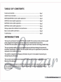
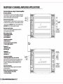
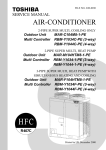
MAXP2760/MAXP2960 2 CHANNEL AMPLIFIER APPLICATIONS
FULL RANGE STEREO
This ;s the most basic application for the MAX PRO
Series 2 channel amplifiers.
FUll. RANGE
SPEAKERS
Q
1. Interconnect cable checklist:
Connect the UNE INPUTS to the Radio/CD with
good quality RCA cables.
3. Crossover frequency control checklist:
f~:
11'11
;e:
4.Line level:
Refer to the section "Setting up systems after installation
for best performance-
~ r~
b£([J1flf1:Ecm[!D
ilSl '
L""",
L
:6),
foo/
S. Bass Remote:
"C.
Plug in the Bass Remote to the amplifier -REMOTE-jack.
NOTE: Minmum tinalloudspeaker impedances:
4 & Z Ohms stereo mode or 4-Ohms mono mode
This amplifier will not do I Ohm stereo or Zli
Ohm mono operation.
FULL RANGE
~t
I
N/A for full range operation.
ro
ro
~r
Z. Crossover Switch:
The X-OVER switch must be in the FlAT position.
~
1
<!!I
TO BAITER'Y +I2V
VIA FUSE
REMOTE TIJRN-ON
:.
CHASSIS GROUND
iii
MONO
This application illustrate the basic mono bridging method
fat alllanzar amplifiers.
Interconnect cable checklist:
A MONO signal source is required. such as would be
available from the mono sub bass output of an active
crossover, whether stand alone. or built into a head
unit or equalizer. Important: Do not be tempted to
FUIl.R.\NGE
STEREO UNE INPUT
VIA. Y-I!.DAPTER
FROM MONO SOURC
Q
connect the hot, or positive outputs. from any source
together to obtain a mono signal, as this CQuid very
well damage the output stage of that source. It is
necessary to feed the SAME signal to both left and right
inputs via a Y-adapter RCA cable. Connect the mono
speaker positive terminal to the LEFT+, and its negative
terminal to RIGHT-.
Switch setting checklist:
-The AMPUFIER X-OVER switch must be in the FUU
position.
Crossover frequency control setting checklist:
N/A for full range operation.
np: If you are using the mono sub bass output of an
active crossover, there isnothing wrong with switching
in the low pass filter in these amplifiers for a steeper
low pass rolloff.
Minimum fin •• loudspeaker impedance:
-4 ohm mono.
VQ
~
~i, <! l
=-c
u--=
~ r~
~ t~
f~:
;e:
0
L
:6),
foo/
~C~ I
~
<!!I
iii
=-r
FUllAANGE
MONOSPEAKER
~ r~
LIlC:>IJ
b£([J1flf1:Ecm[!D
ilSl '
~
~
iii
I
~.
~
n...=
TO BATTER'Y + I 2V
VIA FUSE
:.
REM OTE TIJRN-ON
CHAS SIS GROUND
01
~
-
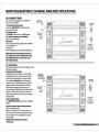
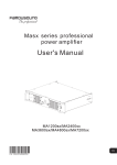
MAXP4260 4 CHANNEL AMPLIFIER APPLICATIONS
4 CHANNEL FULL RANGE SYSTEM
Here we show how to use the 4 channel amplifiers as
straightforward discrete 4 channel full range units.
~
Interconnect c.ble checldlst:
- Connect the four inputs of the amplifier to a Radio/CD
with quality RCA cables,
SWItch .enlng checklist:
-ljZCH X'()VER: FULL
-3/4CH X'()VER: FULL
Crossover frequency control checklist:
Channel. I/Z:
Channel. 3/4:
-HIGH PASS: NfA
-HIGH PASS: NfA
-LOW PASS: NfA
-LOW PASS: NfA
Level control checklist:
='-
"~
j
I"
FUIl..RANGE
co
STERfOUNE '"
INPUTS
~
~I~·
~ f!L
.2
P i
~ [1
~ [:g
~
D
~.
~COl~6(fJLrr
~
~I
I
looJ
0
~
~~I
- Refer to the section "setting up systems after installation for
best performance"
I~
"
~
u
Minimum flnalloud.......ker Impedance.:
.. Z ohm per ch.nnel.
Z or 3 CHANNEL FULL RANGE SYSTEM
Here we show how to use the 4 channel amplifiers as full range
2 or 3 channel units by taking advantage of the mono bridging
capability of alllanzar MAX PRO series amplifiers.
The follwing example shows how to create a 3 channel system
by mono bridging channel pair 3/4. In order to create a 2 channel
system. simply follow the example to also mono bridge channel pair 1f2,
.
~
~'~.~" "
~
=-r
=
:. :Ii
FUll RANGE
SPEMERS
JitO
to
to
to
TOBATTERY+I2V
VIII FUSE
REMOTE TURN-ON
CHI\S5IS GROUND
or
l~
TIP: If you are using the mono sub bass output of an active crossover, there is nothing wrong
with switching in the low pass filter in these amplifiers for a steeper low pass rolloff.
Level control checkli.t:
- Refer to the section "Setting up systems after installation for best performance"
Minmum final loudspeaker impedances:
- 2 ohm per channel in stereo mode.
- 4 ohm mono bridged.
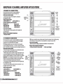
Interconnect cable checklist:
- Connect the inputs of channel pair 1/2 to a suitable stereo source,
e.g. a head unit with good quality RCA cables.
- A MONO signal source is required to bridge channel pair3/4, such
as would be available from the mono sub bass output of an active
crossover, whether standalone, or built into a head unit or equalizer.
Important: Do not be tempted to connect the hot. or positive
outputs, from any source together to obtain a mono signal, as this
could very well damage the outout stage of that source,
- It is necessary to feed the SAME signal to both lett and right inputs
via a Y-adapter RCA cable.
- Connect the mono speaker positive terminal to the RIGHT +, and
its negative terminal to LEFT - as shown.
SWItch .enlng checklist:
-I/ZCH X'()VER: FULL
-3/4CH X'()VER: FULL
Cros.over frequency control checkli.t:
chennel. I/Z:
channel. 3/4:
- HIGH PASS: NfA
_ HIGH PASS: NfA
- LOW PASS: NfA
_ LOW PASS: NfA
-
STEREO
FULL AANGE
OR HIGHS
SPENCERS
!tj
•
1 STEREO
I MONO
FUll. RANGE
UNE INPI./n
ffi
+
STEREO
FUll. RANGE
ORHIGHS
SPEAKERS
TO Bll.TTERY+1ZV
VIA FUSE
REMOTE TURN-ON
CHASSIS GROUND
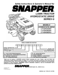
MAXP4260 4 CHANNEL AMPLIFIER APPLICATIONS
2 way active, or b .... mpllfted system with mono bass
Level control checklist:
This application shows how easily a 2 way active system can be
implemented using a MAX PRO series 4 channel amplifier. Channels
I and 2 will be used for highs, and channels 3 and 4 for mono bass.
Refer to the section "setting up systems after in stall ation for best performance"
·2 ohm per channel in stero mode
Interconnect cable checklist:
·4 ohm mono bridged.
Mlnmum ftnalloudspeaker Impedances:
- We need to feed the same signal to both sets of channels, so
must use 2 Y-adapters, one to feed the LEFT signal to channels
I and 3, and the right signal to channels 2and 4, as shown.
~
Mono bass woofer wiring
- Connect the mono speaker positive terminal to the RIGHT +,
and its negaitive terminal to LEFT -.
Switch setting checklist:
• 1/2CH X-oVER: HP
• 3/4CH X-oVER: lP
Crossover frequency control checklist:
channels 1/2
·HIGH PASS: 100 Hz
-LOW PASS: NfA
Channels 3/4:
• HIGH PASS (subsonic!: 20 Hz
• Low PASS: 100 Hz
+
SPEAKERS
!O
STEREO
FUURANGE
OR HIGHS
+
LEFT TO Cfi..\NNELS
I AND 3
STEREO
FULLMNGE
OR HIGHS
SPENCERS
~ MONO
f{tI OR SUB s.\SS
SPENCERS
TO M.TTEIn' + 12V
VIA FUSE
REMOTE TURN-ON
CH.\SSIS GROUND
Please note that these frequency points only. Refer to the
loudspeaker manufacturer specifications and the section
"setting up system after installation for best performance-
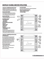
2 way active, or bl-ampllfted system with mono bass,
and faded highsj 10_
Here we present a variation of the previous system. Since
this is a 2 way system, wecan use the front outputs from
a head unit to drive the highs, and the rear output to drive
the bass This method allows the listener to easily adjust
the relative levels of bass to highs, with the front to rear
fade on the head unit. Channels 1 anf 2 will be used for
highs, and channels 3 and 4 for mono bass.
rn
+
STEREO
FUll. RANGE
OR HIGHS
SPENCERS
~STEREO
FU1J.RANGE
STEREOUNE
INPUTS
~FUURANGE
OR HIGHS
r1\
!iJ ORMONO
SUB MSS
SPENCERS
SPENCERS
interconnect cable checklist:
- Use good quality RCA leads to connect the inputs of the
amplifier to the source as shown.
- Follow the instructions as per the previous system for
switch and crossover settings.
-
MAXP42604 CHANNEL AMPLIFIER APPLICATIONS
Front/ear high pass, using a Z channel amplifier
for mono sub bass
The combination of a 2 and a 4 channel amplifier, utilizing their
built in crossovers. makes it a snap to put together a full system
with front and rear highs. with mono sub bass.
Interconnect cable checklist:
- Using good quality RCA cables. feed the front and rear outputs
of a head unit to the inputs of the 4 channel amplifier as shown.
FRONT
INPlm
REJlR
INPlm
FUll RIoNGE
SPEAKERS
- Also connect the LINE OUT of the 4 channel amplifier to the
LINE INPUT of the 2 channel amplifier as shown.
(:g
Mono bass woofer wiring:
TOBATTERY+I'lV
VIA FUSE
-REMIOTE TURN-ON
Connect the mono speaker positive terminal to the LEFT +,
and its negative terminal to RIGHT -.
Switch .etting checklist.
4 channel high. amplifier:
• 1/2CH X'()VER: HP
• 3/4CH X-OVER: HP
Z channel bilss amplifier:
• X'()VER switch: LP
Crossover frequency control checklist:
• 4 channel high. amplifier:
""'0
INlERCONNECT
RCII,"""
Channel. 1/2
• HIGH PASS: 100Hz
LOW PASS: NfA
Channel. 3/4
• HIGH PASS: 100Hz
LOW PASS: NjA
FULlRloNGE
MONO SPEAKER
2 channel bas. amplifier:
• HIGH PASS ISubsonlc filter,: 10Hz to 40Hz
Please note that these frequency points are suggestions only.
Refer to the loudspeaker manufacturer specifications and
the section 'Setting up systems after installation for best
performance"
Level control checklist:
- Refter to the section "Setting up systems after installation
for best performance-
Minimun finalloud.peaker impedances:
• Z ohm per channel in .tereo mode.
·4 ohm mono bridged.
-
TOBATTERY+I'lV
VIA FUSE
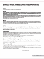
SETTING UP SYSTEMS AFTER INSTALLATION FOR BEST PERFORMANCE
General:
At this point you are ready to get more specific on the settings for your amplifier.
HIgh Pass:
-When in Hi Pass operation, this setting acts as a low frequency cut off for your system reproduction. The point that you set it at cuts off any frequencies from reproduction
beyond this point. The 12 o'clock position is a great starting point. EXAMPLE: If you adjust the High Pass to 100Hz. the amplifier will not play trequencies below 100Hz but
will play trequencies trom 100Hz to the chosen Low Pass trequency.
-When in Low Pass/Bandpass operation, this setting acts as a low frequency cut off for your system reproduction aka Subsonic Filter. The point that you set it at cuts off any
trequencies trom reproduction beyond this point. The 12 o'clock position is a great starting point. EXAMPLE: If you adjust the High Pass to 25Hz. the amplifier will not play
trequencies below 25Hz but will play frequencies from 25Hz to the chosen Low Pass frequency.
-When in Flat/Full operation, the High Pass crossover is bypassed.
BassEQ:
This setting is a fIXed bass boost at 45Hz that is variable from 0-1 OdB. This feature provides impact to your bass, but if not adjusted correctly. it can be over used and cause
damage to your speakers and amplifiers. It is best to slowly turn this setting clockwise until the desired punch is felt. it is not recommended to exceed the 12 o'clock position
unless listening at a low volume or a low recording quali1y as this can result in high distortion and possibly clipping.
Low Pass:
The Low Pass control acts as a ceiling and doesn't allow frequencies to the right of the desired setting to be reproduced. Turning the potentiometer all the way to the right
is a great starting point. EXAMPLE: If you adjust the Low Pass to 120Hz. the amplifier will not play fTequencies above 120Hz but will play frequencies from 120Hz to the
chosen Hi Pass or Subsonic trequency.
-When in Hi Pass operation, this setting is bypassed.
Level Control Setup:
Ensuse that the level is turned completely to the left prior to turning the syetem on. Next you should insert a CD or cassette that you are familiar with to use as a reference,
and turn the head unit volume control to about 80% of its full setting. The system sound level will of course be very low. and the following procedures will help you to match
the amplifier input sensitivities properly to the head unit output signal level.
It is important to match the amplifier LEVEL input sensitMty to the Radio/CD output sensitivity. This can be located in the Radio/CD manual.
If the Radio/CD output sensitivi1y is 2 volts. then adjust the amplifier LEVEL input to 2 volts.
If you are not sure what the Radio output sensitivi1y is. follow these general guide lines:
Turn the level control up SlOWly, till you hear distortion, then back off a few degrrees on the control. If at any point your amplifier goes into protection, you will need to turn
the level to the left a bit and then try again. If you reach a point where the output does not increase, stop turning the level control to the righe as the amplifier/speaker
combo has reached its maxx output in this application.
Z or:l way active systems lalll:
Always start with the bass. or low frequency amplifier as a reference. by turning its control up to the point where distortion is audible. and back it olf some. Now adjust the
level control for the highs or tweeter channels in a 2 way active system. to balance the highs to lows.
In a 3 way active system, match the midrange level to the bass, and then the highs to the midrange and bass. It may be necessary to perform a few iterations of the midrange
and highs level control settings to achieve a satisfactory sound balance.
Sit bIIck and enjoy the music!
-
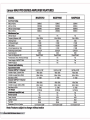
Lanzar MAX PRO SERIES AMPLIFIER FEATURES
MODEL
MAXP2760
MAXP2960
MAXP4260
Out Power Rating
RMSat40hms
MAX at 4 Ohms
MAX at 4 Ohms Bridced
RMSat 2 Ohms
500Wx2
1000Wx2
1200Wxl
BOOWx2
750Wx2
1500Wx2
3000Wxl
1200Wx2
250Wx4
500Wx4
1000Wx2
400Wx4
Yes
10Hz-40KHz
>200
> 95dB
<0.05%
>70dB
0.2V-6.0V
20kQ
Power/Protect
Yes
Yes
Yes
Yes
10Hz-40KHz
>200
> 95dB
<0.05%
>70dB
0.2V-6.0V
20kQ
Power/Protect
Yes
Yes
10Hz-40KHz
>200
> 95dB
<0.05%
>70dB
0.2V-6.0V
20kQ
Power/Protect
Yes
Yes
Yes
Yes
Yes
Hp/FULljLP-BP
40Hz- 2kHz
Hp/FULljLP-BP
40Hz- 2kHz
Hp/FULljLP-BP
40Hz- 2kHz
30Hz- 150Hz
0- 10dB
30Hz- 150Hz
0- 10dB
30Hz- 150Hz
0- 10dB
Miscellaneous Spec
Soft Start Sound
Frequency Response -3dB
Dampinc Factor
SIN Ratio(A-Weight)
THD & Noise
Channel Separation at I KHz
Varible Input Level Control
Input Impedance
Power and Diagnostic LED
Protection(DC, Short, Thermal, Overload)
Power Supply. all MOSFET PWM
MOSFET Outputs
Crossover and Swlthchlng
Input Selector Switch
Crossover SfW for I +Z channel
Variable Hi-pass / Subsonic Filter
Variable Low-pass (Mono 24dB)
Bass Boost at 45Hz
Crossover SfW for 3+4 channel
Variable Hi-pass
Variable Low-pass/ (Mono 24dB)
Bass Boost at 45Hz
UneOutput
Unbalanced InputlRCAJackJ
Remote Control
Power Terminal
Speaker Terminal
Fuse Size
Dimensions (W x H x L) Inches
40Hz- 2kHz
40Hz- 2kHz
40Hz- 2kHz
30Hz- 150Hz
0- 10dB
Full Rance
30Hz- 150Hz
0- 10dB
Full Rance
30Hz- 150Hz
0- 10dB
Full Rance
Yes
Yes
4-GA
8-GA
20Ax3
10. I 6-x2.56-xl 3.86-
Yes
Yes
4-GA
8-GA
30Ax3
10. 16-x2.56-xl 5.83-
Yes
Yes
4-GA
8-GA
40Ax2
10. 16-x2.56-xl 2.8-
Note: Features subject to change without notice
-
TROUBLESHOOTING
Before removing your amplifier, refer to the list below and follow the suggested procedures. Always test the speakers and their wires first.
AMPLIFIER WILL NOT POWER UP.
Check for good ground connection.
Check that remote DC terminal has at least 13.8v DC.
Check that there is battery power on the +terminal.
Check all fuses.
Check that Protection LED is not lit If it is lit. shut off amplifier briefly and then repower it.
HIGH HISS OR ENGINE NOISE (ALTERNATOR WHINEI IN SPEAKERS.
Disconnect all RCA inputs to the amplifierlsj-if hiss/noise disappea,,- then plug in the component drMng the amplifier and unplug its inputs. If hiss / noise
disappea,,- go on until the faulty/noisy component is found.
It is best to set the amplifier's input level as insensitive as possible. The best suQjective SIN ratio is obtainable this way. Try to drive as high a signal level
from the head unit as possible.
PROTECTION LED COMES ON W
EN THE AMPLIFIER IS POWERED UP.
Check for shorts on speaker leads.
Check that the volume control on th head unit is turne(j down low.
Remove speaker leads. and reset the a
plifier. If the Protection LED still comes on. then the amplifier is faulty.
AMPLIFIER(SI GETS VERY HOT.
Check that the minimum spe7 er im edance for that model is correct.
Check for speaker shorts.
Check that there is good airftow ar:ound the amplifier. In some applications, an external cooling fan may be required.
DISTORTED SOUND
Check that the Level controlls) is set to match the signal"level of t ' head unlu ' Check that all crossover
Check for shorts on the sP!'aker leads.
-
())
*+*
!!!"#$%&'