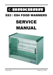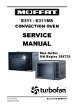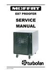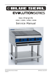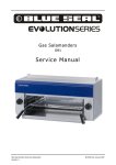
1
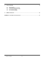
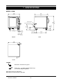
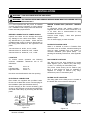
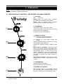
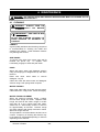
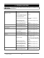
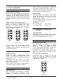
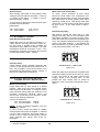
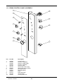
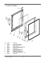
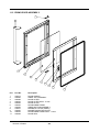
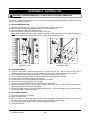
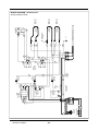
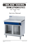
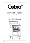
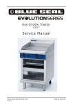
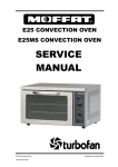
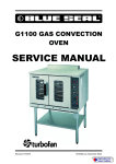
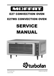
E89M / MS PROOFER AND
HOLDING CABINET
Beginning with S/N 259435
SERVICE
MANUAL
Revision 1/F3608
October, 2003
Manual P/N MOME89
CONTENTS
This manual is designed to take a more in depth look at the E89M / MS prover and holding cabinets for the
purpose of making the unit more understandable to service people.
There are settings explained in this manual that should never require to be adjusted, but for
completeness and those special cases where these settings are required to change, this manual gives a
full explanation as to how, and what effects will result.
SECTION
PAGE NO.
1.
SPECIFICATIONS .............................................................................................................................. 5
2.
INSTALLATION.................................................................................................................................. 8
3.
OPERATION....................................................................................................................................... 9
3.1
3.2
4.
Description of Controls
Explanation of Control System
MAINTENANCE ................................................................................................................................. 12
4.1
4.2
Cleaning
Routine Procedures
5.
TROUBLE SHOOTING GUIDE .......................................................................................................... 14
6.
SERVICE PROCEDURES .................................................................................................................. 16
6.1
6.2
6.3
6.4
Fault Diagnosis
Access
Replacement
Adjustment / Calibration
7.
ELECTRICAL SCHEMATICS ............................................................................................................ 27
8.
ELECTRICAL WIRING DIAGRAMS .................................................................................................. 29
9.
SPARE PARTS .................................................................................................................................. 31
10.
ACCESSORIES / OPTIONS............................................................................................................... 32
IMPORTANT: MAKING ALTERATIONS MAY VOID WARRANTIES AND APPROVALS.
Revision 1/F3608
-3-
11.
PARTS DIAGRAM.............................................................................................................................. 33
11.1
11.2
11.3
11.4
11.5
12.
Main Assembly
Control Panel Assembly (E89M)
Control Panel Assembly (E89MS)
Door Assembly (E89M)
Door Assembly (E89MS)
SERVICE CONTACTS........................................................................................................................ 39
APPENDIX A. Auto Water Fill Kit Instructions ........................................................................................ 41
Revision 1/F3608
-4-
1. SPECIFICATIONS
710
810
(28”)
(32”)
900
WATER ENTRY
515
(201/4”)
51.5
(2”)
117.5
610
(45/8”)
(24”)
68
(22/8”)
SIDE
FRONT
710
(28”)
PLAN
LEGEND
- Electrical connection entry point
- Water entry - 3/4” BSP (Autofill models only)
(1/2” ID Hose adapter supplied)
Dimensions shown in millimetres.
Dimensions in inches shown in brackets.
Revision 1/F3608
-5-
(25/8”)
66.5
(8”)
200
355
(14”)
ELECTRICAL ENTRY
(351/2”)
MODEL: E89M
710
810
(28”)
(32”)
900
WATER ENTRY
515
(201/4”)
51.5
(2”)
117.5
610
(45/8”)
(24”)
68
(22/8”)
SIDE
FRONT
710
(28”)
PLAN
LEGEND
- Electrical connection entry point
- Water entry - 3/4” BSP (Autofill models only)
(1/2” ID Hose adapter supplied)
Dimensions shown in millimetres.
Dimensions in inches shown in brackets.
Revision 1/F3608
-6-
(25/8”)
66.5
(8”)
200
(14”)
355
ELECTRICAL ENTRY
(351/2”)
MODEL: E89MS
LOCATION
To ensure correct operation the following
minimum installation clearances are to be
adhered to:
Rear
Left-hand side
Right-hand side
Provision must
opening.
0mm / 0”
0mm / 0”
25mm / 1”
be allowed
for
the
door
PROVER INTERNAL DIMENSIONS
E89M / MS
Width
Height
Depth
Prover Volume
460mm / 18”
675mm / 265/8”
700mm / 275/8”
0.22m³ / 7.8ft³
PROVER RACK/PAN SIZE CAPACITY
Width
460mm / 18” or
405mm / 16”
660mm / 26”
Depth
RACK POSITIONS
Spacing
74mm / 3”
No. of rack positions: 8
ELECTRICAL SUPPLY SPECIFICATION
OPTIONS
100-120 Volts A.C. 60 Hz, 12.5 A, 1.5kW
208-220 Volts A.C. 50/60 Hz, 6.5A, 1.45kW
220-240 Volts A.C. 50/60 Hz, 7.1 A, 1.7kW
ELECTRICAL PLUG SPECIFICATION
REQUIREMENTS
Australia
3-pin 250V 10A, AS/NZ 3112
Canada
3-pin 125V 15A, NEMA 5-15
New Zealand
3-pin 250V 10A, AS/NZ 3112
United Kingdom 3-pin 250V 13A fused, BS 1363A
United States 3-pin 125V 15A, NEMA 5-15
Other Countries 3-pin 250V 10A minimum, type
to meet country standards
WATER SUPPLY CONNECTION
(Autofill Models Only)
Max Pressure
Min Pressure
550 kPa / 5.5 bar / 80 psi
100 kPa / 1.0 bar / 15 psi
Revision 1/F3608
-7-
2. INSTALLATION
WARNING: THIS APPLIANCE MUST BE GROUNDED.
WARNING: ALL INSTALLATION AND SERVICE REPAIR WORK MUST BE CARRIED OUT BY
QUALIFIED PERSONS ONLY.
It is most important that the prover is installed
correctly and that the operation is correct before
use. Installation shall comply with local electrical,
health and safety requirements.
WATER CONNECTION (AUTOFILL MODELS
ONLY)
BEFORE CONNECTION TO POWER SUPPLY
Connect water supply - Max inlet pressure
550kPa / 80psi.
A connection elbow and sealing washer is
supplied with this unit for direct connection of a
½” ID hose, and is recommended for easy
installation and service.
Unpack and check unit for damage and report
any damage to the carrier and dealer. Report
any deficiencies to your dealer. Check that the
available power supply is correct to that shown on
the rating plate located on the right-hand side
panel.
Turn on water supply to check for leaks.
DOUBLE STACKING UNITS
When it is desired to mount a Turbofan E32
convection oven on an E89, a double stacking kit
must be used. Available from your dealer or
Turbofan distributor (see Spare Parts). For
stacking kit assembly instructions, refer Appendix
B.
100-120 Volts A.C. 60 Hz, 12.5 A, 1.5kW
208-220 Volts A.C, 50/60 Hz, 6.5A, 1.45kW
220-240 Volts A.C. 50/60 Hz, 7.1A, 1.7kW
LOCATION
To ensure correct operation the following
minimum installation clearances are to be
adhered to:
Rear
Left-hand side
Right-hand side
RACK WIDTH POSITIONS
The E89 prover has been designed to accept
either 460mm (18”) or 405mm (16”) wide trays,
1/1 GN, 1/2 /1 GN trays or USA steam pans.
0mm / 0”
0mm / 0”
25mm / 1”
The prover comes factory set for 460mm (18”)
trays, a rack spacer kit (Part no. 025685) is
required to change to 405mm (16”) trays,
Gastronorm pans or USA steam pans.
Provision must be allowed for the door opening.
RATING PLATE LOCATION
ELECTRICAL CONNECTION
The rating plate for the E89 prover is located at
the bottom left corner of the RH side panel.
E89 models are supplied with pre-fitted cords.
Ensure unit is fitted with correct cord and plug for
the installation (refer specifications section).
Should changing of the cord be necessary, gain
access to the electrical connection terminal block
and strain relief clamp by removing the RH side
panel.
L1
Phase
RED
BROWN
BLACK
L2
Ground
Neutral
BLACK
BLUE
WHITE
GREEN
GREEN/YELLOW
Rating Plate
WARNING: THIS APPLIANCE MUST
BE GROUNDED / EARTHED
Figure 2.1
Revision 1/F3608
Figure 2.3
-8-
3. OPERATION
NOTE: A full user’s operation manual is supplied with the product and can be used for further referencing
of installation, operation and service.
3.1 DESCRIPTION OF CONTROLS - E89 PROVER / HOLDING CABINETS
1. FUNCTION
OFF
Unit is off.
PROOF Unit is in proofing mode. (Indicator
illuminates when switched to this position)
89
HOLD
Unit is in holding mode. (Indicator
illuminates when switched to this position)
2. THERMOSTAT
Temperature range 0 - 85°C (32 - 185°F).
1
Indicator illuminates when elements are cycling
ON to maintain set temperature.
Controls the prover air temperature.
3. HUMIDITY CONTROL
1 to 5 Setting for butter based pastries
(croissants, Danish pastries etc.)
5 to 8 Settings for yeast based breads and
doughs.
F
OO
PR
2
Indicator illuminates when elements are cycling
ON to maintain set temperature.
(Controls the cabinet humidity in PROOF mode
only)
LD
HO
Manual Water Fill Models: Open the prover
door. Fill the water trough at the filling spout,
located at the front of the right hand side rack, to
approximately 20mm / ¾” from the top of the
trough. Remember to top up the water trough
when the water level is below the halfway level in
the trough and before the heating element is
exposed.
Auto Water Fill Models: Check that the water
trough is filling, and the heating element is well
covered.
3
4. THERMOMETER
Indicates cabinet temperature.
Dual Centigrade and Fahrenheit scale.
CONDENSATION CHANNEL
Below the door there is a condensation channel
and removable water collection drawer for the
purpose of collecting door condensation run-off.
4
Revision 1/F3608
-9-
The proofing system controls air temperature and
humidity levels by way of an air heating element
and a water tank heating element.
3.2 EXPLANATION OF CONTROL
SYSTEM
The E89M/MS Prover/Holding Cabinets feature
operator controls and an electrical circuit for
which a direct understanding of their operation is
required before carrying out any service work or
fault repair work. The control device functions
and electrical circuit are explained as follows:
The air heating element is positioned in the
bottom of the air circulation ducting inside the
cabinet and is directly controlled by the
user-adjustable thermostat mounted to the control
panel. The thermostat sensing bulb is mounted
inside the cabinet to control the cabinet air
temperature to the control panel setting. An
indicator light on the control panel above this
thermostat will illuminate when the thermostat
has the air heating element operating and will
cycle Off with the thermostat to indicate when the
temperature reaches set point.
The main
thermostat is adjustable up to 85°C (185°F).
Function Switch
A rotary switch on the control panel of these
models functions as the power On/Off switch of
the unit by isolating the Line 1 phase supply.
This switch is a 3 position, 4 pole, multi-function
switch which in the Off position opens circuits all
poles and isolates power from all control and
heating systems. The switch should operate as
illustrated below.
The humidity thermostat mounted on the control
panel controls the water tank heating element,
which in turn maintains the water temperature
between 20°C (68°F) and 85°C (185°F). The
evaporation of the water provides the cabinet
humidity. The setting of the humidity thermostat
(between 1 - 8) controls the rate of water
evaporation and therefore the level of humidity in
the cabinet.
P1 – No function / not used.
P2 – Additional air heating element.
P3 – Humidity control thermostat.
(Auto-fill models only - water solenoid, float
switch, solenoid relay)
P4 – Air heating thermostat, cabinet lights, air
circulation fan motor and control panel
power indicator.
P1
P2
D
HO L
P3
PRO
P4
PWR
OF
OFF
1
P1
2
P2
3
4
1
P1
D
HO L
2
P2
HOLD
P3
PROOF
3
P3
O
PRO
P4
PWR
4
P4
PWR
PROOF
An indicator light on the control panel above the
humidity dial illuminates when the water tank
element is On, and cycles Off when the
thermostat switches the heating element Off to
provide an indication of the humidity control. The
sensing bulb of the humidity thermostat is
mounted to the water tank heating element, which
is immersed in the water tank. Should the water
tank level drop below the heating element the
humidity thermostat will cycle Off due to the
sensing bulb reacting to the radiated heat off the
heating element and will prevent the humidity
water tank heating element burning out through
excessive temperature.
1
2
F
3
4
HOLD
Figure 3.2.1
The air circulation fan, cabinet lights and control
panel power indicator are On continuously on all
E89 models when the function switch is in either
of the PROOF or HOLD positions. The air
circulation fan mounted at the top of the air
delivery ducting ensures that the temperature and
humidity throughout the cabinet is even by
creating a low velocity air circulation system
throughout the prover cabinet.
Hold Mode
When the function switch is turned to the ‘Hold’
position the function switch pole P3 opens to turn
off the humidity control circuit, and pole P2 closes
to connect an additional air heating element to
the air temperature thermostat circuit. In this
mode the air temperature thermostat operates as
it does in the proofing mode, however, in this
case there is an additional air heating element
switched On and Off to provide extra heating
power in this mode. The additional air heating
element is also mounted in the air circulation
ducting.
Proof Mode
In the ‘Proof’ position the function switch poles
P1, P3 and P4 are closed, supplying power to the
dry heat circuit, humidity circuit, cabinet lights and
fan.
Revision 1/F3608
E89M/MS Prover/Holding Cabinets are provided
with a thermometer dial on the control panel to
-10-
provide an indication of the cabinet temperature.
The sensing bulb of this thermometer dial is
mounted next to the sensing bulb of the main
thermostat inside the cabinet.
Auto water fill (option)
E89 Auto-Water fill models provide for a mains
cold water supply connection for automatic water
tank filling and level control. Non Auto-Water fill
models require the operator to manually fill the
water tank and maintain the water tank level as
the water evaporates through operation.
On Auto-Water fill models an electric solenoid
valve, float switch and relay maintain the water
level in the humidity tank. The float switch is
mounted at the rear of the water tank, and when
the water is below the full level it open circuits,
removing power from the coil.
When deenergised, the relay removes power from the
humidity thermostat circuit (therefore switching off
the humidity element), and switches power to the
water solenoid. As the water level reaches the
full level position the float switch contact will
close, re-energising the water solenoid relay,
thereby closing the water solenoid valve and
providing power back to the humidity thermostat.
Accordingly this system will automatically
maintain a full water tank whenever the function
switch is in the “PROOF” position and the mains
water supply is turned on.
Ensuring that the function switch is in the Off
position is necessary whenever removing the
water tank for cleaning as when the water tank is
removed the float switch drops and the water
solenoid valve will open (if the unit is on).
Therefore as a precaution the mains water supply
should also be turned Off whenever removing the
water tank.
Revision 1/F3608
-11-
4. MAINTENANCE
WARNING: ALL INSTALLATION AND SERVICE REPAIR WORK MUST BE CARRIED OUT BY
QUALIFIED PERSONS ONLY.
4.1 CLEANING
WARNING: ALWAYS TURN THE
POWER SUPPLY OFF BEFORE
CLEANING.
IMPORTANT: THIS UNIT IS NOT
WATER PROOF.
DO NOT USE A WATER JET SPRAY TO
CLEAN INTERIOR OR EXTERIOR OF
THIS UNIT.
CABINET
A good quality stainless steel cleaning compound
is recommended for cleaning the inside and
outside of the cabinet. Harsh abrasive cleaners
may damage the surface.
SIDE RACKS
To remove, take hold of the centre rung and lift
towards the prover top.
To replace, hold
horizontally, engage in holes and push down.
DOOR
Wash with warm water and detergent solution
using a soft sponge in straight lines up and down
the door.
Rinse with clean,
detergent. Dry off.
warm
water
to
remove
Clean door seal with warm water and detergent
solution using a soft sponge when required.
WATER TROUGH
Open right hand side rack and remove trough.
Clean with warm, soapy water. Rinse thoroughly.
WATER TROUGH ELEMENT
When the element becomes limed / scaled,
remove water trough and clean. Replace water
trough and half fill with white vinegar or acetic
acid then fill to the normal level with water.
Switch unit on. Set humidity control to ‘8’ and run
for approximately 30 minutes. Remove trough
and clean element with damp cloth when cooled.
Wash out trough and refit.
This procedure is recommended to be done once
a week. Frequency of cleaning the element may
be increased or decreased depending on the lime
depositing on the element.
Revision 1/F3608
-12-
4.2 ROUTINE PROCEDURES
PROCEDURE
INTERVAL
WET ELEMENT
Remove scaling (refer section 4.1).
As required
DOOR SEALS
Inspect door seal on door inside for wear and tear.
DOOR HINGES
Check for wear.
12 months
ELEMENTS
Check that elements are operating.
12 months
Revision 1/F3608
-13-
6 months
5. TROUBLE SHOOTING
WARNING: ALL INSTALLATION AND SERVICE REPAIR WORK MUST BE CARRIED OUT BY
QUALIFIED PERSONS ONLY.
FAULT
THE UNIT DOES NOT
OPERATE / START
POSSIBLE CAUSE
REMEDY
The unit is not plugged into the
wall socket.
Plug in.
The mains isolating switch on the
wall, circuit breaker or fuses are
“off” at the power board.
Turn on.
The power switch on the unit is off. Turn switch on. Indicator will
illuminate.
FAN DOES NOT OPERATE
Incorrect electrical supply.
(Refer fault diagnosis 6.1.1)
Ensure electrical supply correct.
Power / Function switch faulty.
(Refer fault diagnosis 6.1.1)
Replace.
(Refer service section 6.3.2)
Fan motor faulty.
(Refer fault diagnosis 6.1.2)
Replace.
(Refer service section 6.3.9)
PROVER CABINET LIGHT(S) DO Bulb blown.
NOT OPERATE
Replace bulb
(Refer service section 6.3.8)
NO DRY HEAT
Thermostat faulty.
(Refer fault diagnosis 6.1.3)
Replace.
(Refer service section 6.3.3)
Element blown.
(Refer fault diagnosis 6.1.3)
Replace.
(Refer service section 6.3.6)
NO DRY HEAT TEMPERATURE
CONTROL
Thermostat faulty.
(Refer fault diagnosis 6.1.4)
Replace.
(Refer service section 6.3.3)
NO HUMIDITY
Unit is in “HOLD” mode.
Humidity only operates when unit
is in “PROOF” mode.
No water in trough.
Manual Fill: Fill trough with water.
Auto fill: (refer fault: Auto-fill not
filling)
Humidity thermostat faulty.
(Refer fault diagnosis 6.1.5)
Replace.
(Refer service section 6.3.4)
Power / Function switch faulty.
(Refer fault diagnosis 6.1.5)
Replace.
(Refer service section 6.3.2)
Water tank element blown.
(Refer fault diagnosis 6.1.5)
Replace.
(Refer service section 6.3.6)
Humidity thermostat faulty.
(Refer fault diagnosis 6.1.6)
Replace.
(Refer service section 6.3.4)
NO HUMIDITY CONTROL
Revision 1/F3608
-14-
FAULT
SLOW RECOVERY
POSSIBLE CAUSE
REMEDY
Overloading of product.
Reduce batch size.
Door opened unnecessarily.
Do not open unnecessarily.
Incorrect electrical supply.
(Refer fault diagnosis 6.1.1)
Check supply voltage is as per
rating plate voltage.
Door seals deteriorated.
Inspect and replace.
Fan motor faulty.
(Refer fault diagnosis 6.1.2)
Replace.
(Refer service section 6.3.9)
Power / Function faulty
(“HOLD” mode only)
(Refer fault diagnosis 6.1.1)
Replace.
(Refer service section 6.3.2)
Element faulty
(“HOLD” mode only)
(Refer fault diagnosis 6.1.3)
Replace.
(Refer service section 6.3.6)
NO HEATING / HUMIDITY
INDICATOR
Indicator faulty.
(Refer fault diagnosis 6.1.7)
Replace.
(Refer service section 6.3.1)
DOOR DOES NOT CLOSE
Tray in way of door.
Correctly position tray in rack.
Interference with door.
Inspect and repair.
Hinges damaged.
Replace.
(Refer service section 6.3.13)
AUTOFILL WATER NOT FILLING Water supply not turned on.
(Autofill models only)
Blockage in water supply.
AUTOFILL WATER
OVERFLOWING
(Autofill models only)
Revision 1/F3608
Turn water supply on.
Disconnect water supply and
inspect.
Water connection filter blocked.
Clean filter.
(Refer service section 6.3.17)
Water solenoid faulty.
(Refer fault diagnosis 6.1.9)
Replace.
(Refer service section 6.3.16)
Water level float switch faulty.
(Refer fault diagnosis 6.1.9)
Replace.
(Refer service section 6.3.18)
Solenoid relay faulty.
(Refer fault diagnosis 6.1.9)
Replace.
(Refer service section 6.3.15)
Water level float switch faulty.
(Refer fault diagnosis 6.1.9)
Replace.
(Refer service section 6.3.18)
Solenoid relay faulty.
(Refer fault diagnosis 6.1.9)
Replace.
(Refer service section 6.3.15)
Water tank not fitted.
Fit water tank.
Solenoid valve dirty.
Clean solenoid valve.
-15-
6. SERVICE PROCEDURES
WARNING: ENSURE POWER SUPPLY IS SWITCHED OFF BEFORE SERVICING.
WARNING: ALL INSTALLATION AND SERVICE REPAIR WORK MUST BE CARRIED OUT BY
QUALIFIED PERSONS ONLY.
SECTION
6.1
FAULT DIAGNOSIS ........................................................................................................................... 17
6.1.1
6.1.2
6.1.3
6.1.4
6.1.5
6.1.6
6.1.7
6.1.8
6.2
Control Panel........................................................................................................................... 19
Right Hand Side Panel ............................................................................................................ 19
Left Hand Side Panel............................................................................................................... 19
Control Panel (Rear)................................................................................................................ 19
REPLACEMENT................................................................................................................................. 20
6.3.1
6.3.2
6.3.3
6.3.4
6.3.5
6.3.6
6.3.7
6.3.8
6.3.9
6.3.10
6.3.11
6.3.12
6.3.13
6.3.14
6.3.15
6.3.16
6.3.17
6.3.18
6.4
Unit Does Not Operate / Start.................................................................................................. 17
Fan Does Not Operate ............................................................................................................ 17
No Heat ................................................................................................................................... 17
No Dry Heat Temperature Control........................................................................................... 17
No Humidity ............................................................................................................................. 17
No Humidity Control ................................................................................................................ 18
No Heating / Humidity Indicator ............................................................................................... 18
Autofill Not Filling or Overflowing (Autofill Models Only) ......................................................... 18
ACCESS ............................................................................................................................................. 19
6.2.1
6.2.2
6.2.3
6.2.4
6.3
PAGE NO.
Indicator Light .......................................................................................................................... 20
Power /Function Switch ........................................................................................................... 20
Thermostat .............................................................................................................................. 20
Humidity Thermostat ............................................................................................................... 21
Thermometer ........................................................................................................................... 21
Dry Element ............................................................................................................................. 22
Wet Element ............................................................................................................................ 22
Light Bulb / Glass .................................................................................................................... 22
Fan ......................................................................................................................................... 23
Door Handle ............................................................................................................................ 23
Door Catch Magnet ................................................................................................................. 23
Door......................................................................................................................................... 23
Door Glass............................................................................................................................... 23
Door Pivot bushes ................................................................................................................... 24
Relay ....................................................................................................................................... 24
Water Solenoid - Autofill models only...................................................................................... 24
Water Solenoid Cleaning......................................................................................................... 25
Float Switch - Autofill models only........................................................................................... 25
ADJUSTMENT / CALIBRATION........................................................................................................ 26
6.4.1 Door Reversal.......................................................................................................................... 26
Revision 1/F3608
-16-
6.1 FAULT DIAGNOSIS
wiring. Check power at terminal 2. If there is no
power then the thermostat is faulty - replace.
6.1.1 UNIT DOES NOT OPERATE / START
Alternatively the thermostat indicator light should
illuminate when thermostat set to max.
Incorrect electrical supply
Check that the supply voltage across phase and
neutral (L1 and L2) terminals of terminal block is
correct as per the voltage stated on the unit’s
electrical rating plate. If incorrect, check electrical
connection of supply cord, and/or check electrical
supply.
Element blown
Power / Function switch on unit faulty
Resistances;
Ensure that power is isolated from the unit.
Check for continuity through the switch
terminals in each of the settings. The switch
should operate as illustrated below. If not then
the switch is faulty - replace.
208 - 240V models
110 - 120V models
P1
1
P1
1
P1
P2
D
HOL
2
P2
D
HO L
2
P2
HOLD
P3
OF
PRO
3
P3
PROOF
3
P3
PRO
P4
PWR
4
P4
PWR
4
P4
PWR
OFF
PROOF
OF
With thermostat on and heating check voltage
across dry element terminals. If there is no
voltage check wiring. If voltage is correct,
element is faulty - replace.
To test element, disconnect terminals and check
resistance across element.
72 Ω ±3.6 Ω
20.5 Ω ±1 Ω
1
6.1.4 NO DRY HEAT TEMPERATURE
CONTROL
2
Thermostat faulty
3
With thermostat in off position (fully counterclockwise), the heating indicator should be off. If
not, then the thermostat is faulty - replace.
4
6.1.5 NO HUMIDITY
HOLD
Humidity thermostat faulty
Figure 6.1.1
If checks are ok and the unit still does not
operate, check the unit’s wiring and/or
re-diagnose exact fault with unit and refer to
trouble-shooting guide.
With cold proofer, set humidity to ‘8’. Check
power to terminal 1 of bottom (humidity)
thermostat. If there is no voltage then check
wiring. Check power at terminal 2. If there is no
power then the thermostat is faulty - replace.
6.1.2 FAN DOES NOT OPERATE
Alternatively the humidity thermostat indicator
light should illuminate when thermostat set to
max.
Fan motor faulty
Power / Function switch faulty
Check the supply voltage across motor
terminals. If there is no voltage with function
switch on then check the electrical connections of
supply wiring.
Ensure that power is isolated from the unit.
Check for continuity through the switch
terminals as illustrated below. If not then the
switch is faulty - replace.
If voltage is correct then isolate unit from power,
then check the oven fan for free rotation.
Remove any obstruction.
P1
If fan is free to spin and the voltage supply is
correct, then the motor is faulty—replace.
6.1.3 NO HEAT
1
P2
D
HO L
2
P3
PROOF
3
P4
PWR
4
Thermostat faulty
With cold prover, set thermostat to maximum
position. Check power to terminal 1 of top
thermostat. If there is no power then check
Revision 1/F3608
PROOF
Figure 6.1.2
-17-
Element blown
Water level float switch faulty
With humidity thermostat on and heating check
voltage across wet element terminals. If there is
no voltage check wiring. If voltage is correct,
element is faulty - replace.
To check correct operation of float switch
remove the float switch wire connections from
terminal 8 and terminal 5 on relay. With full water
tank (float switch in raised position) float switch
should be closed circuit. With empty water tank
(float switch in lower position) float switch should
be open circuit. If not, float switch is faulty—
replace.
To test element, disconnect terminals and check
resistance across element.
Resistances;
208 - 240V models
110 - 120V models
72 Ω ±3.6 Ω
20.5 Ω ±1 Ω
Solenoid relay faulty
E89 auto-fill models are fitted with a 2 pole
change over relay, with its coil controlled by the
float switch located in the water through / tank.
When the water level is below the full position the
coil is not energised, allowing the relay to supply
power to the water solenoid. In this position the
relay should have no power at terminals 3,4 and
8, but power at terminals 1,2,5, and 6,
6.1.6 NO HUMIDITY CONTROL
Humidity thermostat faulty
Switch the prover on and set the humidity to ‘4’.
Check that the humidity thermostat cycles on /
off, and using a suitable probe measure the
temperature of the water in the trough. The water
temperature should be 50°C/120°F ± 10%. If the
temperature continues to rise above this then the
humidity thermostat is faulty - replace.
6.1.7 NO HEATING / HUMIDITY INDICATOR
2
4
6
1
3
5
7
8
Indicator faulty
SOLENOID RELAY - TANK FILLING
Check voltage across indicator terminals with
controls on and appropriate thermostat turned on
fully. If the voltage is correct and indicator is not
illuminated then the indicator is faulty - replace. If
there is no voltage then check wiring.
Figure 6.1.3
When the water level reaches the full position the
float switch supply’s power to the relay coil, which
in turn cuts power to the water solenoid and
supply’s power to the humidity tank. In this
position the relay should have no power at
terminals 1 and 2, but power at terminals 3,4,5,6,
and 8.
6.1.8 AUTOFILL NOT FILLING OR OVER
FLOWING (AUTOFILL MODELS ONLY)
Water solenoid faulty
Empty water tank so float switch is in lowest
position. With power ON check voltage across
water solenoid coil terminals. If voltage is correct
(refer electrical rating plate) but solenoid is not
operating, disconnect electrical supply and
remove wire connections from solenoid. Check
solenoid coil windings resistance.
Correct coil resistance:
208 - 240 volt models
110 - 120 volt models
4
6
1
3
5
7
8
SOLENOID RELAY - TANK FULL
3650 Ω
1100 Ω
Figure 6.1.4
NOTE: If open circuit/high resistance, then the
coil is faulty– replace.
If coil is correct, rewire and listen for audible
solenoid click when power is supplied. If solenoid
can be heard functioning and water supply is
turned on but no water is entering tank, remove
water solenoid and fittings and check for
blockages.
Revision 1/F3608
2
-18-
6.2 ACCESS
6.2.4 CONTROL PANEL—REAR
6.2.1 CONTROL PANEL
1) Remove two screws at bottom of control
panel.
Power Indicator
Power / Function Switch
Two
Screws
Figure 6.2.1
Dry Heating Indicator
2) Control panel can now be lowered and hinged
on lower bracket.
3) When closing control panel ensure no wires
are trapped.
Dry Thermostat
6.2.2 RH SIDE PANEL
1) Undo the four screws holding the panel in
place.
2) Pull out at bottom, lower to remove.
Wet Heating Indicator
Wet Thermostat
Four
Screws
Thermometer
Figure 6.2.2
6.2.3 LH SIDE PANEL
Figure 6.2.4
1) Undo the four screws holding the panel in
place.
2) Pull out at bottom, lower to remove.
Four
Screws
Figure 6.2.3
Revision 1/F3608
-19-
6.3 REPLACEMENT
6.3.1 INDICATOR LIGHT
1) With control panel open (refer 6.2.1)
remove the wires from the back of the neon.
Thermostat Phial
Support
Bracket Screw
Neon Wires
Figure 6.3.3
Figure 6.3.1
4) Withdraw old thermostat phial through hole
under bracket in side of proofer.
2) From back push neon through front of panel
rotating clockwise.
5) Remove sleeving from old thermostat and fit
to replacement thermostat.
3) Push new neon in from front of panel, and
reconnect wires.
Fibreglass Sleeve
6.3.2 POWER / FUNCTION SWITCH
Thermostat Phial
1) Remove knob off front of power switch.
2) Open control panel (refer 6.2.1).
Figure 6.3.4
3) Remove two screws, remove switch.
6) Undo two screws securing thermostat to
control panel and remove.
Two
Screws
Two Screws
Figure 6.3.2
4) Mount new switch and transfer wires from the
old switch.
Figure 6.3.5
6.3.3 THERMOSTAT
1) Pull knob off front of thermostat.
7) Attach new thermostat to control panel and
transfer wires to new thermostat.
2) Open control panel (refer 6.2.1).
8) Re-assemble in reverse order.
3) With door open, remove right hand side rack.
Undo thermostat support bracket screw and
remove bracket.
9) Ensure hole in prover wall through which the
thermostat capillary passes is re-sealed with
RTV silicone sealant.
Revision 1/F3608
-20-
7) Attach new thermostat to control panel, and
transfer wires to new thermostat.
6.3.4 HUMIDITY THERMOSTAT
1) Pull knob off front of thermostat
8) Re-assemble in reverse order.
2) Open control panel (refer 6.2.1).
9) Ensure hole in prover wall through which the
thermostat capillary passes is re-sealed with
RTV silicone sealant.
3) With door open, remove right hand side rack
and water trough. Undo humidity thermostat
support bracket screw and remove bracket.
Remove clip holding capillary to element.
6.3.5 THERMOMETER
Capillary
Clip
1) Open control panel (refer 6.2.1)
2) With door open, remove right hand side rack
(Lift off supports, and remove).
Humidity
Support
Bracket
Screw
3) Undo thermometer support bracket screw and
remove bracket.
Figure 6.3.6
4) Remove thermostat support bracket in side
wall, withdraw old humidity thermostat phial
through hole under the bracket.
Support
Bracket Screw
5) Remove plastic sleeving from old thermostat
and fit to replacement thermostat.
Plastic Sleeve
Figure 6.3.9
4) Withdraw old thermometer phial through hole
under bracket in side of cabinet.
5) Undo 2 nuts securing thermometer to control
panel and remove.
Thermostat Phial
Figure 6.3.7
Two Nuts
6) Undo two screws securing thermostat to
control panel and remove.
Two Screws
Figure 6.3.10
6) Attach new thermometer to control panel.
7) Insert new thermometer phial through cabinet
side and re-attach bracket.
8) Re-assemble in reverse order.
9) Ensure hole in prover wall through which the
thermostat capillary passes is re-sealed with
RTV silicone sealant.
Figure 6.3.8
Revision 1/F3608
-21-
6.3.6 DRY ELEMENT
Capillary
Clip
1) Remove RH side panel (refer 6.2.2), remove
wires from element terminals, noting position.
Support
Bracket
Screw
2) With door open, remove right hand side rack.
Figure 6.3.13
5) Unscrew the element from RH side (outside)
of proofer.
Element
cover
Screws
Element
Screws
Figure 6.3.11
3) Undo the two screws holding the element
cover and remove cover.
Proofing
Element
Terminals
Figure 6.3.14
6) Pull element carefully into prover to remove.
7) Replace and reassemble in reverse order.
Hold Element
Terminals
Wet Element Ratings
208 - 240 Volt Models
72 Ω ±3.6 Ω.
110 - 120 Volt Models
20.5 Ω ±1 Ω
Figure 6.3.12
6.3.8 LIGHT BULB / GLASS
4) Unscrew the element from RH side (outside)
of prover. Pull element carefully to remove
from inside of proofer.
5) Replace
order.
and
re-assemble
in
1) Open the prover door.
2) Pull off lamp cover.
reverse
Dry Element Ratings
208 - 240 Volt Models
72 Ω ±3.6 Ω.
110 - 120 Volt Models
20.5 Ω ±1 Ω
Lamp
Covers
6.3.7 WET ELEMENT
1) Remove RH side panel (refer 6.2.2), and
remove wires from (rear) element terminals.
2) With door open, remove right hand side rack
and water tank.
Figure 6.3.15
3) Remove thermostat support bracket screw
(on element) and remove bracket.
3) Unscrew bulb out of fitting.
4) Remove clip securing thermostat capillary to
element.
Revision 1/F3608
4) Screw in replacement bulb.
5) Refit lamp cover.
-22-
6.3.9 FAN
6.3.11 DOOR CATCH MAGNET
1) Remove RH side panel (refer 6.2.2)
1) Open prover door.
2) Remove wires from fan motor, noting their
positions.
2) Unscrew two screws securing magnet to
door.
3) Replace magnet catch and re-assemble in
reverse order.
Fan
Motor
Bracket
Screw
Fan Motor
Terminals
Door
Magnet
Two
Screws
Figure 6.3.16
3) Remove fan motor bracket, one screw.
4) Slide fan assembly out of proofer.
5) Replace and re-assemble in reverse order.
Figure 6.3.19
6.3.12 DOOR
6.3.10 DOOR HANDLE
1) Remove two screws from top of door holding
hinge to door.
1) Open prover door.
2) Remove two screws (E89M) or four screws
(E89MS), remove handle.
Hinge Pivot
(Two Screws)
Hinge Body
Two Screws
(E89M)
Figure 6.3.20
2) Slide door out at top and remove hinge pivot.
3) Lift door vertically off bottom hinge body (if
sticky loosen bottom hinge body two screws).
Figure 6.3.17
4) Remove bottom hinge pivot from door.
Two Screws top
and bottom
(E89MS)
5) Fit hinge pivots (top and bottom) to new door.
6) Re-assemble in reverse order.
6.3.13 DOOR GLASS
1) Remove door as per steps one to three of
section 6.3.12
Figure 6.3.18
2) Lay door face down on bench and remove
door seal.
3) Replace and re-assemble in reverse order.
Revision 1/F3608
-23-
3) Remove door inner (14 screws) and remove
glass.
6.3.15 RELAY - AUTOFILL MODELS ONLY
4) Clean glass and replace in reverse order.
Ensure silicone seals have not been
displaced from door outer and door inner.
1) Remove RH side panel (refer 6.2.2).
2) Remove two screws securing relay to bracket.
Door Outer
Door Inner
Two Screws
Figure 6.3.24
Door Glass
3) Secure new relay to bracket.
14 Screws
4) Transfer wires from old relay to new relay.
Door Seal
5) Replace RH side panel.
Figure 6.3.21
5) Reassemble and refit door in reverse order.
6.3.16 WATER SOLENOID - AUTOFILL
MODELS ONLY
6.3.14 DOOR PIVOT BUSHES
1) Remove RH side panel (refer 6.2.2).
1) Remove door as per steps one to three of
section 6.3.12.
2) Remove wires from solenoid, noting their
positions.
2) Remove two screws (top and bottom) holding
hinge body to proofer.
Solenoid
Wires
Two screws
Brass Fitting
Two
Screws
Figure 6.3.25
Figure 6.3.22
3) Remove brass fitting from solenoid.
4) Remove two screws securing solenoid to
bracket, and withdraw solenoid.
3) Door pivot bush can now be removed and
replaced.
5) Secure new solenoid with screws, and
re-assemble in reverse order.
Door Pivot
Bush
Figure 6.3.23
4) Re-assemble in reverse order.
Revision 1/F3608
-24-
6.3.17 WATER SOLENOID CLEANING
Float Switch
Sleeve
1) Disconnect water supply from the water
solenoid.
2) Remove the sieve from the water valve
assembly by pulling firmly away from the
assembly with a pair of pliers.
Float Switch
Nut
Float Switch
Figure 6.3.28
8) Remove the float switch from the bracket,
replace, and reassemble in reverse order.
Sieve
NOTE: Ensure float switch bracket is RTV
silicone sealed to prevent steam leakage.
Figure 6.3.26
3) Clean the sieve, removing all dirt and grime.
4) Replace the
water supply.
sieve
and
reconnect
the
6.3.18 FLOAT SWITCH - AUTOFILL
MODELS ONLY
1) Remove RH side panel (refer 6.2.2).
2) Remove float switch
noting their positions.
wires
from
relay,
3) Remove brass fitting from rear of float switch.
4) Remove RH side rack and water trough from
inside proofer.
Two Nuts
Brass Fitting
Figure 6.3.27
5) Undo two nuts from outside cabinet, and two
screws inside cabinet securing float switch
bracket to proofer.
6) Remove float switch assembly from proofer.
NOTE: The float switch bracket has been
silicone sealed, so it may therefore be
necessary to cut around the bracket with a
sharp knife to assist with removal. Clean off
all remaining silicone.
7) Remove the float switch sleeve, and undo the
nut securing the float switch to the bracket.
Revision 1/F3608
-25-
6.4 ADJUSTMENT / CALIBRATION
When changing to LH hinged door.
6.4.1 DOOR REVERSAL
Remove magnet
opposite side.
1) Whilst supporting door remove bottom hinge
body (two screws) and remove door.
Important: Redundant plate holes in LH side
wall must be filled to stop steam ingress into
wall cavity.
plate
and
transfer
to
6) Fit bottom hinge body to top on opposite side,
centre hinge on slots.
Two Screws
7) Whilst holding door in place fit remaining
hinge body to bottom, securing door in
position.
8) Remove door handle (E89M only) (refer
6.3.10) and refit in the higher setting, using
the extra screw position.
Hinge Body
9) Ensure door seal is removed and refitted with
join at bottom, centred over middle screw
head when closed.
Figure 6.4.1
2) Remove top hinge body (two screws).
10) Refit LH side panel.
3) Remove four cover screws covering alternate
hinge holes. Refit cover screws on opposite
side.
Cover Screws
Figure 6.4.2
4) Remove LH side panel (refer 6.2.3).
5) When changing to RH hinged door.
Remove LH magnet plate cover screws and
clips from inside LH wall (Do not fit cover
screws to old magnet position).
Transfer door magnet plate to opposite side.
Magnet Cover
Screws
Magnet Plate
Figure 6.4.3
Revision 1/F3608
-26-
Revision 1/F3608
P2
2
P2
P1
1
P1
P4
4
3
P3
P4
P3
4
3
PROOF
HOLD
OFF
3
4
OF
P RO
PWR
P3
P4
GROUND
2
D
HOL
1
P2
P1
2
1
P4
4
P3
3
FUNCTION SWITCH
P2
2
P1
1
FUNCTION SWITCH OPERATION
-27HOLD
ELEMENT
600W 110V
800W 240V
PILOT
LIGHT
DRY
ELEMENT
600W 110V
800W 240V
HUMIDITY
ELEMENT
600W 110V
800W 240V
HUMIDITY
THERMOSTAT
2
2
THERMOSTAT
1
1
PILOT
LIGHT
POWER
FAN
LIGHT
2x 15W 110V
2x 25W 240V
LIGHT
7. ELECTRICAL CIRCUIT SCHEMATIC
7.1 E89 Manual Water Fill Holding / Prover Cabinet
Revision 1/F3608
GROUND
P2
2
P2
P1
1
P1
P4
4
3
P3
P4
P3
4
3
PROOF
HOLD
OFF
3
4
OF
PRO
PWR
P3
P4
HOLD
ELEMENT
600W 110V
800W 240V
2
D
HOL
1
P2
P1
2
1
P4
4
P3
3
FUNCTION SWITCH
P2
2
P1
1
FUNCTION SWITCH OPERATION
-28PILOT
DRY
ELEMENT
600W 110V
800W 240V
LIGHT
HUMIDITY
ELEMENT
600W 110V
800W 240V
POWER
PILOT
LIGHT
HUMIDITY
THERMOSTAT
2
2
THERMOSTAT
1
1
FAN
2x 15W 110V
2x 25W 240V
LIGHT
LIGHT
WATER
SOLENOID
RELAY
1
2
3
4
5
6
8
7
N/C
FLOAT
SWITCH
7.2 E89A Auto Water Fill Prover / Holding Cabinet
12
18
13
P4
4
P3
1
4
FUNCTION
SWITCH
3
P1
P2
DRY
THERMOSTAT
(0-85°C)
2
1
2
Revision 1/F3608
-29-
EARTH
1
2
WET
THERMOSTAT
(30-85°C)
1
3
6
4
18
7
11
10
23
8
3
2
5
17
1
15
14
MAINS
TERMINAL
BLOCK
HUMIDITY
INDICATOR
TEMP
INDICATOR
POWER
INDICATOR
LIGHTS
25W 240V
15W 110V
LIGHT
LIGHT
34
33
32
L
16
23
24
29
28
27
N
26
25
30
E
35
6
31
29
7
28
27
11
DRY
ELEMENT
HOLD
ELEMENT
WET
ELEMENT
26
POWER SUPPLY CORD
EARTH
WIRE MARKING
"VIVID" PEN
25
32
FAN MOTOR
600W 110V
800W 240V
600W 110V
800W 240V
600W 110V
800W 240V
8. ELECTRICAL WIRING DIAGRAM
8.1 E89 Manual Water Fill
-30-
FLOAT SWITCH
WATER
SOLENOID
22
19
20
19
21
3
1
5
6
RELAY
4
2
9
18
12
7
8
9
13
P4
4
P3
1
4
FUNCTION
SWITCH
3
P1
P2
DRY
THERMOSTAT
(0-85°C)
2
1
2
Revision 1/F3608
EARTH
1
3
6
4
18
7
11
10
23
8
3
2
WIRE MAKING
"VIVID" PEN
2
WET
THERMOSTAT
(30-85°C)
1
5
17
1
22
15
14
MAINS
TERMINAL
BLOCK
HUMIDITY
INDICATOR
TEMP
INDICATOR
POWER
INDICATOR
LIGHTS
25W 240V
15W 110V
LIGHT
LIGHT
34
33
32
L
16
23
24
29
28
27
N
26
25
30
E
35
6
31
29
7
28
27
11
DRY
ELEMENT
HOLD
ELEMENT
WET
ELEMENT
26
POWER SUPPLY CORD
EARTH
WIRE MARKING
"VIVID" PEN
25
32
FAN MOTOR
600W 110V
800W 240V
600W 110V
800W 240V
600W 110V
800W 240V
8.2 E89A Auto Water Fill
9. SPARE PARTS
REPLACEMENT PARTS LIST
CONTROLS
022789
020823
022787
024527
020823
021472
020849
023857
022788
Switch - Function
Knob - Function
Thermostat (Temperature)
Thermostat (Humidity)
Knob - Temperature Thermostat
Knob - Humidity Thermostat
Neon Indicator (240V)
Neon Indicator (110V)
Thermometer (Dual °C & °F)
AUTO FILL OPTION
020851
021617
021534
021535
022250
Solenoid Valve (240V)
Solenoid Valve (110V)
Relay (240V)
Relay (110V)
Float Switch
MOTOR & ELEMENTS
013998
013999
014001
015759
015224
015320
Fan / Motor (240V)
Fan / Motor (110V)
Dry Element - 800W (240V)
Dry Element - 600W (110V)
Wet Element - 800W (240V)
Wet Element - 600W (110V)
DOOR
SA1686
SA1687
021468
025519
020082
020083
017905
018947
025988
Door Assembly (E89M)
Door Assembly (E89MS)
Handle (E89M)
Handle (E89MS)
Hinge Top Assembly (Assembled with bush)
Hinge Bottom Assembly (Assembled with bush)
Hinge Bush
Magnetic Catch
Door Seal
RACKS
025604
025608
025685
Revision 1/F3608
Rack RH
Rack LH
Rack Spacer Kit
-31-
11. PARTS DIAGRAMS
17
36
25
27
34
1
2
3
4
5
6
8
7
10
9
11
12
13
14
15
18
16
21
20
19
22
23
26
24
28
29
30
35
31
32
AUTO-FILL
UNITS ONLY
33
37
38
11.1 MAIN ASSEMBLY
Revision 1/F3608
-33-
Pos
Part No.
Description
1
2
3
4
-----025598
020082
020083
017905
025609
025685
025608
025604
-----025566
022758
025732
025601
013890
014001
015759
013885
021342
014218
014219
025575
025567
012271
012275
015224
015230
019238
025573
013586
002441
002138
025580
013998
013999
DOOR ASSEMBLY (REFER SECTION 11.4 & 11.5)
DOOR SEAL
HINGE TOP (ASSEMBLED WITH BUSH)
HINGE BOTTOM (ASSEMBLED WITH BUSH)
HINGE BUSH
RACK SPACER (OPTIONAL EXTRA)
RACK SPACER KIT
LH RACK WA
RH RACK WA
CONTROL PANEL ASSEMBLY (REFER SECTION 11.2 & 11.3)
HANGER STUD
CATCH PLATE
CONDENSATE DRAWER
RACK STANDOFF
CASTOR - SWIVEL
DRY ELEMENT - 800W (240V)
DRY ELEMENT - 600W (110V)
CASTOR - RIGID
LAMP HOLDER (c/w 25W 240V BULB)
BULB 24W (240V)
BULB 15W (115V)
SIDE PANEL
WATER TANK
CLAMP BOTTOM
CLAMP TOP
WET ELEMENT - 800W (240V)
WET ELEMENT - 600W (110V)
SNAP BUSH 19mm
TERMINAL BLOCK PANEL
TERMINAL BLOCK
INSULATOR
CABLE CLAMP
FAN MOTOR BRACKET
MOTOR - (240V)
MOTOR - (110V)
5
6
7
8
9
10
11
12
13
14
15
16
17
18
19
20
21
22
23
24
25
26
27
Auto-fill units only
28
29
30
31
32
33
34
35
36
37
38
022097
022252
022253
022998
025574
020851
021617
022250
021534
021535
020869
024702
021619
Revision 1/F3608
SENSOR BRACKET
FLOAT SWITCH SLEEVE
ADAPTOR & LOCKNUT
REDUCING SOCKET 3/8” x 1/8”
WATER TUBE
WATER SOLENOID - (240V)
WATER SOLENOID - (110V)
FLOAT SWITCH
RELAY - (240V)
RELAY - (110V)
CONNECTOR 3/8”F x 1/4” COMPRESSION
WATER SOLENOID BRACKET
REAR SERVICE PANEL TOP
-34-
11.2 E89M CONTROL PANEL ASSEMBLY
1
2
5
3
6
4
6
7
8
9
Pos
Part No.
Description
1
004995
005002
022789
022787
024527
020849
020823
021472
022788
024694
Control panel (Blue Seal)
Control panel (Bakbar)
Selector switch
Thermostat 0-85°C (Dry)
Thermostat 30-85°C (Wet)
Pilot light (240V)
Knob
Knob (Humidity)
Thermometer
Control panel hook
2
3
4
5
6
7
8
9
Revision 1/F3608
-35-
11.3 E89MS CONTROL PANEL ASSEMBLY
1
3
2
6
4
7
5
7
8
9
10
Pos
Part No.
Description
1
2
025582
025585
025586
025584
022789
022787
024527
023857
020849
020823
021472
022788
024694
Control panel
Overlay °C (Bakbar)
Overlay °C (Blue Seal)
Overlay °F (Moffat)
Selector switch
Thermostat 0-85°C (Dry)
Thermostat 30-85°C (Wet)
Pilot light (110V)
Pilot light (240V)
Knob
Knob (Humidity)
Thermometer
Control panel hook
3
4
5
6
7
8
9
10
Revision 1/F3608
-36-
11.4 E89M DOOR ASSEMBLY
1
2
3
4
5
6
7
8
9
10
Pos
Part No.
Description
1
2
3
4
5
6
7
8
9
10
11
12
020082
025603
021468
025597
090202
025599
020083
025593
018947
025600
090203
025598
HINGE TOP ASSEMBLY
DOOR HANDLE BRACKET
DOOR HANDLE
DOOR OUTER POWDER COATED
DOOR OUTER SEAL - 2.02m
DOOR GLASS
HINGE BOTTOM ASSEMBLY
DOOR INNER FRAME
MAGNETIC CATCH (INNER)
MAGNET MOUNTING PLATE
DOOR INNER FRAME SEAL - 2.00m
DOOR SEAL
Revision 1/F3608
-37-
11
12
11.5 E89MS DOOR ASSEMBLY
2
1
3
4
5
6
7
8
9
10
11
Pos
Part No.
Description
1
2
3
4
5
6
7
8
9
10
11
025519
020082
025588
090202
025599
025593
020083
018947
025600
090203
025598
DOOR HANDLE
HINGE TOP ASSEMBLY
DOOR OUTER
DOOR OUTER SEAL - 2.02m
DOOR GLASS
DOOR INNER FRAME
HINGE BOTTOM ASSEMBLY
MAGNETIC CATCH (INNER)
MAGNET MOUNTING PLATE
DOOR INNER FRAME SEAL - 2.00m
DOOR SEAL
Revision 1/F3608
-38-
11. SERVICE CONTACTS
AUSTRALIA
VICTORIA - MOFFAT PTY
HEAD OFFICE AND MAIN WAREHOUSE
740 Springvale Road
Mulgrave VIC 3170
Spare Parts Department
NEW SOUTH WALES - MOFFAT PTY
Unit 8/142 James Ruse Drive
Rosehill NSW 2142
Spare Parts
Tel (03) 9518 3888
Fax (03) 9518 3838
Free Call 1800 337 963
Fax (03) 9518 3895
Free Call 1800 337 963
Fax (03) 9518 3895
QUEENSLAND - MOFFAT PTY
30 Prosperity Place
Geebung QLD 4034
Spare Parts
Free Call 1800 337 963
Fax (03) 9518 3895
SOUTH AUSTRALIA - MOFFAT PTY
28 Greenhill Rd
Wayville SA 5034
Spare Parts
Tel (08) 8274 2116
Free Call 1800 337 963
WESTERN AUSTRALIA - MOFFAT PTY
PO Box 689
Joondalup Business Centre WA 6027
Spare Parts
Tel (08) 9305 8855
Free Call 1800 337 963
NATIONAL COVERAGE FOR 24 HOUR SERVICE OR MAINTENANCE DIAL
FREE CALL 1800 622 216 (AUSTRALIA ONLY)
CANADA
Lessard Agencies Limited
PO Box 97
Stn “D”
Toronto, ONT M6P 3J5
Tel (416) 766 2764
Fax (416) 760 0394
Free Call 1 888 537 7273
NEW ZEALAND
CHRISTCHURCH - MOFFAT LTD
16 Osborne St
PO Box 10-001
Christchurch
Spare Parts
Free Call 0800 Moffat
(0800 663 328)
Tel (03) 389 1007
Fax (03) 389 1276
AUCKLAND - MOFFAT LTD
4 Waipuna Road
Mt Wellington
Auckland
Spare Parts
Revision 1/F3608
Tel (09) 570 6630
Fax (09) 570 0099
Free Call 0800 Moffat
(0800 663 328)
-39-
UNITED KINGDOM
BLUESEAL LTD
Units 6-7 Mount St
Business Park
Birmingham B7 5QU
England
Tel 0121-327 5575
Fax 0121-327 9711
UNITED STATES OF AMERICA
MOFFAT INC.
3765 Champion Blvd
P.O. Box 4129
Winston-Salem
NC27115
Tel 1-800 551 8795
Fax 336 661 9546
NATIONAL COVERAGE FOR SERVICE OR MAINTENANCE DIAL
FREE CALL 1800 551 8795 (USA ONLY)
Revision 1/F3608
-40-
APPENDIX A. AUTOFILL KIT
WARNING: ENSURE POWER SUPPLY IS SWITCHED OFF BEFORE COMMENCING.
To convert a manual fill E89 prover to an auto-fill model, upgrade kit #025683 (240V) or #025752 (110V)
needs to be installed as follows.
A. PROVER PREPARATION
1)
2)
3)
4)
Remove RH side panel (four screws), pull out at bottom and lower to remove.
Remove water inlet blanking plate from rear of unit (four screws). (H).
Open RH side rack and remove water trough.
Remove blanking plate from inside prover (Two bolts). (A).
Note: Blanking plate has been silicone sealed, therefore it maybe necessary to cut around the blanking
plate with a sharp knife to assist with removal. Clean off all remaining silicone.
B
A
B
E
C
G
H
D
F
INTERNAL VIEW
EXTERNAL VIEW
B. KIT INSTALLATION
1) Install the float switch bracket and assembly to inside of prover (B). Place a bead of RTV silicon
sealant around back face of float switch bracket before securing to liner to ensure prover is sealed.
2) Fit water solenoid and mounting bracket (F) to rear panel as shown (two screws).
3) Fit 1/4” copper tube (C) to outlet tube (B) and water solenoid (F) tighten all fittings.
4) Fit relay (D) to terminal block panel (two screws).
5) Connect wiring as per wiring diagram provided (refer overleaf).
6) Fit new rear service panel (G) to rear of prover.
7) Affix max water pressure label (E) to rear panel above water inlet.
8) Connect cold water supply (1/2” ID hose) to water connection elbow. Ensure leak free connection.
Maximum water pressure is 550 kPa (80psi).
9) Fit elbow to water solenoid, ensure supplied washer is used. Turn water supply on and check for leaks,
no water should be flowing into trough.
C. RE-COMMISSIONING
1) Re-fit RH side panel (four screws)
2) Replace water trough.
3) Turn the power on, check that water trough fills, and stops filling approximately 20mm from the top of
the tank. (Note: Humidity element will not heat until tank is filled to correct level).
4) Turn power supply off, empty water trough and repeat step 3 above.
5) Close RH side rack.
Revision 1/F3608
-41-
-42-
FLOAT SWITCH
WATER
SOLENOID
22
19
20
19
21
3
1
5
6
18
RELAY
4
9
2
4
7
8
9
P4
13
P3
12
4
1
3
P1
P2
DRY
THERMOSTAT
(0-85°C)
EARTH
1
3
6
4
18
7
11
10
23
8
3
2
WIRE MAKING
"VIVID" PEN
2
WET
THERMOSTAT
(30-85°C)
1
Revision 1/F3608
2
1
2
FUNCTION
SWITCH
5
17
1
22
15
14
MAINS
TERMINAL
BLOCK
HUMIDITY
INDICATOR
TEMP
INDICATOR
POWER
INDICATOR
LIGHTS
25W 240V
15W 110V
LIGHT
LIGHT
34
33
32
L
16
23
24
29
28
27
N
26
25
30
E
35
6
31
29
7
28
27
11
DRY
ELEMENT
HOLD
ELEMENT
WET
ELEMENT
26
POWER SUPPLY CORD
EARTH
WIRE MARKING
"VIVID" PEN
25
32
FAN MOTOR
600W 110V
800W 240V
600W 110V
800W 240V
600W 110V
800W 240V
Wiring changes in bold.
WIRING DIAGRAM - AUTOFILL KIT