1
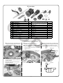
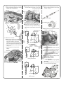
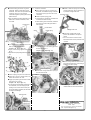
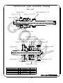
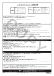
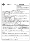
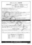
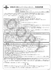
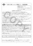
5-Speed Transmission Instruction Manual
Item No.:02−04−0077
・Thank you for purchasing one of our products. Please strictly follow the instructions to install and
use the products.
・Before installing the products, please be sure to check the contents of the kit. If you have any questions about the products, please kindly contact your local TAKEGAWA dealer.
CO
◎ Please note: Illustrations and photos may vary from actual hardware.
Applicable models and frame No.
KSR110 (A3): KL110A-A04501∼
K L X110 (A4): LX110A-A23003∼ From ‘05 models onward
Read all instructions first before starting the installation.
○ This kit is for exclusive use in KSR110 & KLX110. Please note that the kit cannot be installed on any other models of motorcycles.
○ Installation of this kit requires engine removal / mounting and crankcase splitting. At some stages of the installation, some special tools are required.
Besides, this instruction manual, as well as a HONDA’s service manual, is prepared for those who have acquired basic skill and knowledge.
Therefore, those who are not sklled or do not have sufficient knowledge may not be able to install the kit correctly.
○This instruction manual covers the installation work only after the procedures of the engine removal from the body, disassembly of a cylinder head,
cylinder, piston, clutch cover, flywheel, generator cover, and primary and scondary clutch assemblies, and the splitting of the crankcase.
Please do the removal work referring to KAWASAK’s service manual for KSR110 / KLX110 for the removal procedures before this stage.
○ Gaskets, O-rings, and packings must be replaced with new ones at the time of disassembly. Since this kit does not include gaskets, O-rings,
packings, etc. which are necessary for engine disassembly, please purchase these gaskets, O-rings, packings, etc separately.
○ This kit is applicable to ‘05 models onwards. In case this kit will be installed on ‘04 or earlier models, you are requested to purchase a KAWASAK’s
genuine change lever for ‘05 onward models.
○ You are discouraged from using this kit on a motorcycle of 138cc or 178cc engine displacement. We recommend that the kit be used on a motorcycle
of less than 125cc engine displacement.
When you use this kit on a motorcycle of 138cc or 178cc displacement, it is understood that you do so on your own responsibility, which please note.
○ Please be informed that, mainly because of improvement in performance, design changes, and cost increase, the product specifications and prices are
subject to change without prior notice.
○ This manual should be retained for future reference.
PY
Special instruction for Thailand made: KSR110 ( KL110CBF / Vin #JKAKL110CCDA00058 and up) To make smooth gearshift, please replace following
parts at the same time Kawasaki genuine parts.
14014-1118 plate position
13236-1256 lever comp
Machining of a left-side crankcase is needed for the installation of this kit. Please contact a machining workshop for this processing. Please prepare the
processing drawing. The following show the envisioned possibility of injuries to human bodies and property damage as a result of disregarding the
CAUTION following cautions.
・Before starting the installation, make sure the engine and muffler are cool at below 35 degrees Celsius. (Otherwise, you will burn you.)
・Do the installation with right tools. Always use a torque wrench to screw bolts and nuts tight and securely to the specified torque.
(Otherwise, these parts may get damaged or fall off, resulting in accidents.)
・Do not use or process other parts than those included in the kit or specified parts. Otherwise, the breakage of parts is highly likely to follow.
・The installation of this kit will change the gear change pattern to the return system of 1-down-4-up. Change gears infallibly only after you have
completely disengaged the clutch. Changing gears forcibly or without disengaging the clutch on the manual-gear shift motorcycle will cause the
gears and other parts to get damaged.
・Before riding, check every hardware like screws and nuts for slack and for abnormal sound. When you notice something abnormal with your
motorcycle while riding down a road, immediately stop riding and check what went wrong with the motorcycle.
◎ Please be informed that, mainly because of improvement in performance, design changes, and cost increase, the product specifications and rices are subject to change without prior notice.
◎ No return accepted after installation.
◎ This manual should be retained for future reference.
Important Notice from TAKEGAWA
Though we have developed and designed each tuning-up part to have a certain level of strength and durability, the wrong use or handling of them will most
likely increase the fear of parts breakage. Therefore, you are kindly requested to use these parts with great care as special parts, not as stock parts.
Features
This is a kit for 5-speed transmission with a gear-ratio for sport driving as compared with a standard 4-speed transmission. Docks of each gear are tapered
to prevent the gear from coming out. A wide range of settings will be available when this kit is used in combination with a final gear. Also available "5sp to
6sp conversion" kit (02-04-0078).
1st
2nd
3rd
4th
5th
6th
gear
gear
gear
gear
gear
gear
Stock 4-speed transmission on KSR110
3.000 (36/12)
1.937 (31/16)
1.350 (27/20)
1.086 (25/23)
TAKEGAWA's close
2,692
2.000
1.578
1.333
1.238
-1-
5-speed transmission TAKEGAWA's close 6-speed transmission
(35/13)
2,692 (35/13)
(32/16)
2.000 (32/16)
(30/19)
1.578 (30/19)
(28/21)
1.333 (28/21)
(26/21)
1.181 (26/22)
1.086 (25/23)
Dec./15/’
10
Kit includes:
7
2
1
8
CO
3
14
9
No.
1
2
3
4
5
6
7
8
9
10
11
12
13
14
15
11
10
Part Name
Main shaft assembly
Counter shaft assembly
Gear shift drum
Shift drum cam
Dowel pin, 4 x 10
Thrust washer, 12 mm
Kick starter gear, 27T
Change shaft lever COMP.
Change shaft return spring
Left gear shift fork
Center gear shift fork
Position lever spring
Return spring bolt
Shift fork shaft
Drive-shaft bearings retainer set
4
13
Qty
1
1
1
1
4
1
1
1
1
1
1
1
1
2
1
15
6
12
5
Repair Part Item No.
in packs of
Please see the Transmission Gear Assembly
Drawing on the last page of this Manual.
24301-KL1-T10
1
24411-KL1-T10
1
00-02-0049
5
00-02-0073
2
28211-KL1-T00
1
24610-KL2-T00
1
24651-KL1-T00
1
24213-KL1-T00
1
00-02-0135
1
00-02-0214
1
92001-KL1-T00
1
02-04-0029
2
00-00-0068
1
PY
※Please order repair parts with the Repair Part Item No. Without the repair part item NO., we may not be able to accept
your orders. Some parts are only available as a set. In this case, please order them with the set number.
∼ Installation Instructions ∼
1.● Process a left-side crankcase as per the
instructions. (Please see the machining drawing of the crankcase.)
3.● Prepare a suitable stand to place a
crankcase on.
● Change the spring with a provided spring.
● Aligning a hole on the shift drum cam with
●Put a stock locating pin into a gear shift drum,
and fit the drum into the right-side crankcase.
In case it’s hard to put in the pin, insert it with
a plastic hammer.
the locating pin on the drum, fix a cam. ●Install dowel pin with face down taper side.
Locating pin
Dowel pins
Position lever spring
Left-side case
2.Detaching the drive-shaft bearings retainer
from the right side crankcase, install the one
included in the Kit.
※ Install the washer with the flat surface
toward the bearings.
Torque: 10 N・m (1.0 kgf・m)
Tapered
-2-
Dec./15/’
10
● Place a holder and tighten up a cap bolt.
5.● Apply engine oil to pawls on each shift fork,
6.● Detach a stock kick gear from the kick ※ Apply screw locking agent to the cap bolt.
Torque: 6 N・m (0.6 kgf・m)
and fit the forks into grooves on each gear.
starter. And apply engine oil to a kick gear
of the kit, and fix it.
Change speed pull-rod
Cap bolt
Holder
Center fork
Left fork
CO
Starter gear
Right fork
●Set the shift drum at a NEUTRAL position.
※ Pay attention to the location of each fork.
● Apply engine oil to the supplied shift rod,
and put the rod through shift forks, sliding
each shift fork. And install this unit onto the
case.
Drum cam
3
5
14.5
2
N
1
4.● Invert the crankcase.
●After applying grease to a provided 12mm
thrust washer, attach it to the countershaft.
After putting together a mainshaft
assembly and countershaft assembly, fit
them into the right-side crankcase at a time.
※ Take care to prevent a thrust washer from
coming off.
※ Apply engine oil to every gear and
bearing.
PY
Washer
Left gear shift fork
18
● Put the kick starter into a hole on the
right-side crankcase.
※Please note that the kick starter cannot be
fixed after joining together the crankcases.
Mainshaft
30.5
Countershaft
7.● Remove dirt and dust remaining on the
mating surfaces of the right- and left-side
crankcases, and degrease the mating
surfaces.
● Apply liquid packing to the mating surface
of the left-side crankcase.
Recommended sealant:
KAWASAKI Bond
(silver-color liquid gasket)
92104-002
※ Do not apply liquid packing to the portion
A., as shown in the figure below.
Center gear shift fork
Drum
Kick starter
40
Position roller
“TAKEGAWA KL1-L”
stamped here
● Apply grease to a stock washer, and fix it
to the tip of a kick shaft.
18
40
4
Align marks each other
A
○
Right gear shift fork
(Genuine parts)
-3-
Dec./15/’
10
8.● Fix two locating pins and O-ring to the
10.Invert the crankcase.
13.● Detach a shift arm spring from a stock
crankcase. Attach a stock spacer to the mainshaft. And attach the processed left
crankcase, and join a right and left
crankcases together by hitting them with a
plastic hammer.
A
※Align the tip ○
of the kick shaft with a kick
shaft hole on the left crankcase, and fix the cases.
●Put a return spring tip into a hole on the kick shaft, and rotate the spring clockwise.
Put the other spring tip into a hole on the
crankcase.
● Attach a plastic spring guide.
※ Check that the crankshaft, mainshaft and
countershaft rotate smoothly.
※ While rotating the countershaft, rotate the
change shaft lever, which please fix to
a provided change shaft lever.
CO
Locating pins
shift drum and check if the gear shifts to each position.
Kick starter
Change shaft lever
Return spring
Guide
O-ring
Shift arm spring
14.● Insert kit’s change shaft into the
position as illustrated in the picture
below.
※ You cannot insert it into the center,
because the bolt and the protrusion will
interfere.
Stock spacer
● Fix screws on the crankcase, and screw
them up in the numerical order.
Torque: 6 N・m (0.6 kgf・m)
※ Apply screw locking agent to the screw
No.10.
※Wipe off the liquid packing that will squeeze
out.
③
④
②
PY
11.● Remove the return spring bolt in the R
crankcase. Apply screw locking agents to
kit’s bolt and tighten it.
Torque:22N・m(2.2kgf・m)
Protrusion
15.● Set the change shaft arm to the holder,
and insert the protrusion of the change
shaft into the return spting.
⑤
⑥
⑩
Return spring bolt
⑨
①
⑧
12.● Install kit’s change shaft return spring to
the case and the bolt.
⑦
9.● Attach a spring and pin to the shift drum.
● Attach an O-ring to a neutral switch, and
attach the switch to the case. ● Apply liquid packing to the lower screws,
and tighten two screws.
Torque: 3 N・m (0.3 kgf・m)
※ As a hole will be made after processing of
the crankcase, never fail to apply liquid packing to the screws at the lower part.
If no liquid packing is applied, this will cause
the engine oil leakages.
Return spring
16.● Referring to the service manual,
reinstall back the removed hardware.
Neutral switch
Co.,Ltd.
Liquid packing
applied here
3-5-16 Nishikiorihigashi Tondabayashi
Osaka Japan
TEL : 81-721-25-1357 FAX : 81-721-24-5059
URL : http://www.takegawa.co.jp
-4-
Dec./15/’
10
Crankcase Machining
Type of Cutter
:Flat end mill, or blue nosed-end mill (under R1)
CO
Process Standard:Diameter when measured with bearings in the middle
:Depth when measured with crank case's mating surface in the middle
Where to process:Shaded portion
Caution:Cover the bearings with a masking to prevent chips and shavings from falling
into them
Remark:Take note that this machining leaves a hole on the spot for mounting a lower
neutral switch
Counter shaft side
Diameter
Depth
Machining Sizes
Main shaft side
PY
67mm (2.638in) with ball bearings
in the middle
48mm (1.890in) from crankcase's
mating surface
※Rasp these
porsions to make them
1mm (0.039in) lower.
Diameter
Depth
45mm (1.772in) with needle bearings
in the middle
38mm (1.496in) from crenkcase's
mating surface
Left side crankcase
Depth should be
measured from
this point
A hole will be left on this threaded portion
5
,
Dec./15/ 10
Transmission gear assembly drawing
Main shaft
Main shaft/M2 gear(16T)
M5 gear(21T)
CO
23210―KL1―T10
23491―KL1―T10
M1 gear(13T)
M3/4 gear(19T/ 21T)
23431―KL1―T00
23461―KL1―T00
Spacer(Stock)
Spline washer 17mm
00―02―0023
PY
External circlips 17mm
00―02―0005
Counter shaft
C5 gear(26T) Thrust washer B 17mm
23501―KL1―T00
Shift clutch
23310―KL1―T00
00―02―0056
C1 gear(35T) C4 gear(28T) C3 gear(30T) C2 gear(32T)
23420―KL1―T00
23471―KL1―T00
23481―KL1―T00
23451―KL1―T10
Thrust washer 12mm
Counter shaft
00―02―0073
23221―KL1―T00
Thrust washer S 17mm
Spline washer 17mm
00―02―0024
00―02―0023
External circlips 17mm
External circlips 17mm
00―02―0005
00―02―0005
Spline washers 17mm
00―02―0023
Part Name
Spline washers 17mm
Thrust washer S 17mm
External circlips 17mm
Thrust washer B 17mm
Thrust washer 12mm
Qty
4
1
5
1
1
Repair Part Item No.
00-02-0023
00-02-0024
00-02-0005
00-02-0056
00-02-0073
In packs of
5
2
5
1
2
6
,
Dec./15/ 10