1
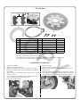
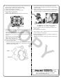
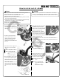
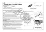
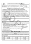
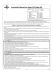
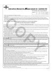
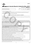
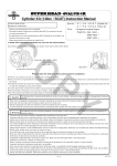
Instruction Manual for Big Floating Disk Kit
for KSR110 & KSR-I / II
CO
Item No.:06―08―1496
Fitting models & frame nos:
KSR110 :KL110A-000001 ∼
KSR- Ⅰ :MX 50B-000001∼
KSR- Ⅱ :MX 80B-000001∼
・Thank you for purchasing one of our TAKEGAWA’s products.
・You are requested to follow the below-mentioned instructions in installing this kit. Should you have any questions about the products, please kindly contact your local dealer.
◎ Please note that, in some cases, the illustrations and photos may vary from the actual hardware.
∼ Features ∼
○ The outer diameter of the disk is φ 225 (The outer diameter of KSR110’s genuine disk is φ 200, and that of KSR-II is φ 220).
○ One-way two-pot caliper is included in the Kit
○Though KSR-110, KSR-I & -II have different fork brackets, you can install this caliper onto all of them just by choosing the suitable screw mounting holes.
○ The disk is made of rust-resistant and highly durable stainless steel.
○ The rotor hub is made of A7075S.
○ This Kit comes with a stainless blade hose and banjo bolt.
PY
Please read the following instructions before installation
◎ This Kit does not come with brake fluid, which please purchase separately. (Above DOT4 or BF-4)
◎ Do not mix different brands of fluid. (The blended use of fluid may cause technical troubles or chemical change.)
◎ The thread pitch of the supplied banjo bolts is 10 x 1.25. Before starting installation, check that the master cylinder has the same thread pitch.
◎ We recommend that the brake be installed by a qualified motorcycle technician at a well-equipped facility. (Otherwise, accidents may take place.)
◎ Before driving after the installation of parts onto the motorcycle, operate the brake lever until the brake pad firmly presses the disk and the brake surely
works, (The failure of this work is likely to lead to accidents.)
◎ As the brake is not sufficiently on after the installation of a new disk and brake pad, drive carefully paying heed to how the brake works.
◎ We do not take any responsibility for any accident or damage whatsoever arising from the use of the kit not in conformity with the instructions in the manual.
◎ We shall be held free from any kind of warranty whatsoever of products other than this product if the glitch takes place on the other products than this one after the installation and use of this product.
◎ You are kindly requested not to contact us about the combination of our products with other manufacturers'.
◎Please order repair parts referring to Item Nos and reference Nos described in this manual. For further information, please contact your local motorcycle
dealers.
◎ Please do the installation securely, referring to a Kawasaki’s genuine service manual for the fitting models as described at the top right-hand corner of
this page.
The following show the envisioned possibility of injuries to human bodies and property damage as a result of disregarding the
CAUTION following cautions.
・Always try to drive your motorcycle at legal speed, abiding by the laws.
・Work only when the engine and muffler are cool. (Otherwise, you will get burned.)
・Do the installation with right tools. (Otherwise, breakage of parts or injuries to you may take place.)
・Always use a torque wrench to screw bolts and nuts tight and securely to the specified torque.
(Otherwise, these parts may get damaged or fall off, resulting in accidents.)
・As some products and frames have sharp edges or protruding portions, please work with your hands protected.
(Otherwise, you will suffer injuries.)
・Before riding, always check every hardware like screws for slack. If you find slack ones, screw them securely up to the specified torque.
(Otherwise, improper tightening may cause parts to come off.)
The following show the envisioned possibility of human death or serious injuries to human bodies as a result of disregarding the
WARNING following warnings.
・Do not get oil or grease on the brake disk rotor or brake pad. If oil &/or grease adhere to these parts, change the brake pad and/or degrease the
brake disk rotor.
・If you find damaged parts, be sure to replace them with new ones.
◎ Please be informed that, mainly because of improvement in performance, design changes, and cost increase, the product specifications and prices
are subject to change without prior notice.
◎ This manual should be retained for future reference.
-1-
Feb./24/’
09
∼ Kit includes ∼
1
2
A
CO
No.
1
2
3
4
5
6
A
3
Part Name
Front brake caliper Assy.
Disk rotor, φ225
Brake hose, 960 mm
Banjo, 25°
Banjo bolt
Sealing washer
Front brake pad set
4
Qty
1
1
1
2
2
4
1SET
5
Repair Part Item No.
06-08-117
45200-KL1-T00
02-01-0293
00-07-0037
00-07-0038
00-07-0010
06-08-0020
6
In packs of
1
1
1
1
1
10
1SET
PY
※Item No. A is included in No. 1.
※Please note that in ordering repair parts, be sure to quote the Repair Part Item No.
Otherwise, we may not be able to accept your orders.
There are some parts, however, for which we are not in a position to accept your order in just the quantity
to be used. In this case, please take them in the quantity packed.
∼ Installation Procedures ∼
1.Check the Kit contents.
5.Bleed the brake fluid.
2.Prepare tools suitable for the work.
3.Make sure your motorcycle is secure on a racing or other stand.
※ Preparation of this instruction manual is premised on the installation
onto KSR110.
4.Before raising the front tire off the ground, remove a caliper, cotter pin
and axle nut, first.
※ The motorcycle will get unstable if you do the work with the front body of the motorcycle being raised off the ground.
※ The caliper bolt will be reused.
Detach the caliper and brake hose.
※Removal of the oil bolt could cause the brake fluid to leak out of the master cylinder.
※If the brake fluid adheres to the paintwork or plated portion, it gives a severe damage like peeling or discoloring of the surface. Wash away the brake fluid with water immediately after it stuck to the surface.
-2-
Feb./24/’
09
6.First, raise the front body off the ground on a front upstand or jack,
11.Put the sealing washer, banjo and sealing washer through the
and then remove an axle shaft to detach the wheel.
※ Before working, make sure your motorcycle is secure.
7.Remove the brake disk from the wheel.
8.Replace the disk with the one coming with the Kit.
※ Apply thread lock to the disk bolt.
Torque: 27 N・m (2.8 kgf・m)
※ Be sure to degrease the mating surface of the brake disk pad.
supplied banjo bolt in this order. And install this unit onto the master cylinder and caliper.
12.Attach the brake hose to banjos. First, decide on at what angle to install the banjo and how to route the brake hose, and then tighten the
banjo bolt and fittings on the brake hose to the specified torque.
CO
Torque
for banjo bolt : 13 ∼ 15 N・m (1.3 ∼ 1.5 kgf・m)
for fittings : 5 ∼ 6 N・m (0.5 ∼ 0.6 kgf・m)
9.Mesh the protrusion inside the speedometer gear housing with the gear
drive cutout on the wheel. Mesh a gear-housing stopper with a stopper
on the fork, and install the wheel onto the front fork.
Attach the axle from the left side in the travel direction, and tighten the ※ For the air-bleeding, refer to the air-bleeding procedures in the
attached sheet.
※ Purchase brake fluid separately.
PY
axle nut loosely for now. And demount the front body from the front upstand.
Tighten the axle nut to the specified torque.
Place a new cotter pin onto the axle nut.
Torque: 64 N・m (6.5 kgf・m)
※ Be sure to use and install a new cotter pin.
10.Attach the supplied caliper.
※On the mounting surface, the caliper has mounting holes for KSR110
13.After installation of parts, check every section. And if nothing wrong
is found, test-drive your motorcycle.
※Usually, the brake is not sufficiently on just after the installation of a new disk and brake pad.
So, drive your motorcycle, carefully paying heed to how the brake works.
and KSR-I / II as shown in the fig. below. Install it referring to the fig.
Torque: 25 N・m (2.5 kgf・m)
KSR Ⅰ - Ⅱ
KSR110
Co.,Ltd.
3-5-16 Nishikiorihigashi Tondabayashi Osaka Japan
TEL : 81-721-25-1357 FAX : 81-721-24-5059
URL : http://www.takegawa.co.jp
-3-
Feb./24/’
09
How to let air out of a brake
Warning:
Notice:
CO
○ Do not get dust or water in the brake fluid when adding the fluid.
○ Do not use brake fluid, mixing different types of fluid.
○ NEVER reuse the used drained brake fluid.
○ NEVER reuse the used sealing washers.
○NEVER let the brake fluid adhere to the paintwork, plastics and rubber ○Never let the oil or grease adhere to a brake-disk rotor or brake pad. Should oil or grease adheres, degrease the rotor or change the pad.
○ In case you find damaged parts, be sure to replace them with new ones.
parts, as the fluid damages them.
○If the air gets mixed in the hydraulic system by, for example, removing the brake hose, let the air out of the hydraulic system.
○ Always follow the specified torque.
○ Always use the designated brake fluid only.
○ Detach two flat pan screws on the master cylinder assembly, and
remove a master cylinder cap and
diaphragm.
○ Connect a transparent bleeder hose to a bleeder valve on the caliper, and receive the drained brake fluid in the suitable cup placed at the tip of the other end of
the hose.
○Keep holding the brake lever, tighten
the bleeder valve on the caliper.
○ Release the brake lever slowly, and
keep the lever in the fully released
position for a few seconds.
①Holding the brake lever, ease the PY
bleeder valve on the caliper by half
a turn. And tighten up the valve again.
② Release the brake lever slowly, and keep the lever in the fully released position for a few seconds.
○ Repeat the above work of No.1 and 2 until no air bubble blows out of
bleeder valve.
☆Check the brake fluid level from time to time, and add the fluid when it is close to the lower level mark.
○If the air is not mixed in the brake oil,
tighten the bleeder valve to the
specified torque.
○ Add brake fluid to the upper level
mark in the oil cup in the master cylinder.
Note: Do not get dust or water in.
Note:Do not use brake fluid,
mixing different types of
fluid.
DOT4 brake oil (BF-4)
Note: Be sure to follow the
specified torque.
Torque: 6 N・m (0.6 kgf・m)
○ Add the brake fluid up to the upper
level mark in the oil cup. And install
the diaphragm and master cylinder
cap with a flat pan screw.
○ Ease the bleeder valve by half a
turn. And repeat squeezing and
releasing the brake lever until the
brake fluid flows out of the bleeder
valve in large amounts.
☆ Do the work, paying heed to the
remaining amounts of brake fluid.
Note: Never let in the dust or
water.
Note: Do not use brake fluid,
mixing different types of fluid.
DOT4 Brake oil (BF-4)
As the case may be, add the brake
fluid.
Brake lever