1
Errata
Title & Document Type: 11848A Phase Noise Interface Service Manual
Manual Part Number: 11848-90004
Revision Date: June 1990
HP References in this Manual
This manual may contain references to HP or Hewlett-Packard. Please note that HewlettPackard's former test and measurement, semiconductor products and chemical analysis
businesses are now part of Agilent Technologies. We have made no changes to this
manual copy. The HP XXXX referred to in this document is now the Agilent XXXX.
For example, model number HP8648A is now model number Agilent 8648A.
About this Manual
We’ve added this manual to the Agilent website in an effort to help you support your
product. This manual provides the best information we could find. It may be incomplete
or contain dated information, and the scan quality may not be ideal. If we find a better
copy in the future, we will add it to the Agilent website.
Support for Your Product
Agilent no longer sells or supports this product. You will find any other available
product information on the Agilent Test & Measurement website:
www.tm.agilent.com
Search for the model number of this product, and the resulting product page will guide
you to any available information. Our service centers may be able to perform calibration
if no repair parts are needed, but no other support from Agilent is available.
SERVICE
MANUAL
HP 11848A
PHASE NOISE
INTERFACE
n
u
SO'—
H
'-vt; = G F
™.;
%-;
B ,. t
. , » . ,j„
'.<.
■
,
-
^
-
<©; ®-
a
^•
*$.
2
CP
{&
o
9
:■ -■-
OS-it. i. ■
« i
■
#
&
«r
G)
O '■'
June 1990
11848-90004
1
".,,,.„„„
[VJ
HEWLETT
PACKARD
HP 11848 A
PHASE NOISE INTERFACE
(Including Option 301)
Service Manual
SERIAL NUMBERS
This manual applies directly to instruments with
serial numbers prefixed:
3138A and all MAJOR changes that apply to your instrument
rev.02NOV92
For additional important information about serial
numbers, refer to "INSTRUMENTS COVERED BY
THIS MANUAL" in Section 1.
Third Edition
"This material may be reproduced by or for the
U.S. Government pursuant to the Copyright License
under the clause at DFARS 52.227-7013 (APR 1988)"
Copyright ©HEWLETT-PACKARD COMPANY 1987
EAST 24001 MISSION AVENUE, TAF C-34, SPOKANE, WASHINGTON, U.S.A. 99220
Service Manual HP Part 11848-90004
Microfiche Service Manual HP Part 11848-90011
Printed In U.S.A.: MAY 1990
m
HEWLETT
PACKARD
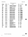
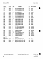
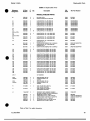
Model 11848A
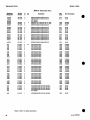
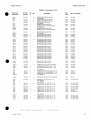
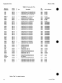
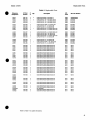
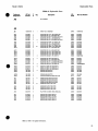
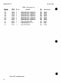
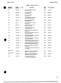
Replaceable Parts
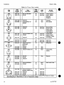
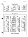
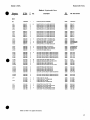
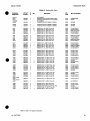
Table 6-3. Replaceable Parts
Mfr.
Code
Mfr. Part Number
ANALYZER INTERFACE ASSEMBLY (NEW)
ANALYZER INTERFACE ASSEMBLY (RESTORED)
28480
28480
11648-60103
11848-69103
1
ANALYZER INTERFACE ASSEMBLY (NEW)
28480
11848-60203
6
6
3
3
4
4
CAPACTTORfXD 1UF 10<X> 60VDC
CAPACrTOrVFXD 1UF 10% 50VDC
CAPACITORfXD 180PF +-6% 200VOC CER
CAPACrrORfXD 2.2UF +-20% 50VDC CER
CAPACrrOR-FXD .01UF +-10% 100VDC CER
28480
28480
28480
28480
28480
0160-5469
0160-5469
0160-4617
0160-0128
0160-4832
0180-1746
6
28
66289
160D166X9020B2
0160-0128
0160-0128
0160-4832
3
3
4
CAPACfTOR-FXD 16UF+-10H 20VDC TA
NOT ASSIGNED
CAPACrrOR-FXD 2£UF +-20% 60VDC CER
CAPACfTORRCD Z2UF +-20% 50VDC CER
CAPACrTOFM=XD .01 UF +-10% 100VDC CER
28480
28480
26480
0160-0128
0160-0128
0160-4832
A3C11
A3C12
A3C13
A3C14
A3C15
0160-4832
4
28480
0160-4832
0160-4822
0160-4832
2
4
CAPACTTOR-FXD .01UF + -10% 100VDC CER
NOT ASSIGNED
NOT ASSIGNED
CAPACITOR-FXD 1000PF +-5% 100VDC CER
CAPACfTORfXD .01UF +-10% 100VDC CER
28480
28480
0160-4822
0160-4832
A3C16
A3C17
A3C18
A3C19
A3C20
0180-0291
0160-5568
0160-5568
0160-5568
0160-3324
3
6
5
5
7
CAPACrrORBCD 1 U F + - 1 0 * 35VDC TA
CAPACITOR-FXD 4700PF +-5% 200VDC
CAPACITOR-FXD 4700PF + -6% 200VDC
CAPACITOR-FXD 4700PF + -6% 200VDC
CAPACrrOR-FXD 1UF +-6% 100VDC MET-POLYC
66289
28480
28480
28480
28480
150D105X9035A2
0160-5568
0160-5568
0160-5568
0160-3324
A3C21
A3C22
A3C23
A3C24
A3C25
0160-3324
0160-3324
0160-3324
0160-3324
0160-3324
7
7
7
7
7
CAPACrTOR-FXD
CAPACITOR-FXD
CAPACITOR-FXD
CAPAcrroRfXD
CAPACITOR-FXD
1UF
1UF
1UF
IUF
1UF
100VDC MET-POLYC
100VDC MET-POLYC
100VDC MET-POLYC
IOOVDC MET-POLYC
100VDC MET-POLYC
28480
28480
28480
28480
28480
0160-3324
0160-3324
0160-3324
0160-3324
0160-3324
A3C26
A3C27
A3C28
A3C29
A3C30
0160-3324
0160-3324
0160-5550
0160-5550
0160-5550
7
7
6
5
.5,
CAPACITOR-FXD
CAPACfTOR-FXD
CAPAcrror+FXD
CAPACITORfXD
CAPACITOR-FXD
1UF +-S% 100VDC MET-POLYC
1UF +-5% 100VDC MET-POLYC
. I U F +-5% IOOVDC MET-POLYC
.1UF +-5% 100VDC MET-POLYC
.1UF +-5% 100VDC MET-POLYC
28480
28480
28480
28480
28480
0160-3324
0160-3324
0160-5550
0160-5550
0160-5550
A3C31
A3C32
A3C33
A3C34
A3C35
0160-5540
0160-5540
0160-5540
0180-1746
0160-3563
3
3
3
5
6
CAPACrrOR-FXD
CAPACITOR-FXD
CAPACITOR-FXD
CAPACITOR-FXD
CAPACITOR-FXD
.01UF +-5% 100VDC
.01UF + - 5 % 100VDC
.01UF + - 5 % 100VDC
15UF+-10% 20VDC TA
10UF + - 5 % 50VDC MET-POLYC
84411
84411
84411
56289
28480
HEW-249
HEW-249
HEW-249
150D156X9020 B2
0160-3563
A3C36
A3C37
A3C38
A3C39
A3C40
0160-3324
0160-3324
0160-3324
0160-3324
0160-3324
7
7
7
7
7
CAPACITCFWCD
CAPACRTOR-FXD
CAPACITORFXD
CAPACRTOR-FXD
CAPACITOR-FXD
1UF + - 5 %
1UF +-£%
I U F +-5%
1UF + - 6 %
I U F +-S%
28480
28480
28480
28480
28480
0160-3324
0160-3324
0160-3324
0160-3324
016043324
A3C41
A3C42
A3C43
A3C44
A3C4S
0160-3324
0160-6550
0160-5550
0160-5550
0160-5540
7
5
5
5
3
CAPACITOR-FXD
CAPAcrroR-FXD
CAPACrTOR-FXD
CAPACITOR-FXD
CAPACITOR-FXD
1UF + - 5 % IOOVDC MET-POLYC
. I U F +-5% IOOVDC MET-POLYC
.1UF +-6% IOOVDC MET-POLYC
.IUF +-S% 100VDC MET-POLYC
.01UF +-5% IOOVDC
28480
28480
28480
28480
84411
0160-3324
0160-5550
0160-5550
0160-5550
HEW-249
A3C46
A3C47
A3C48
A3C49
A3C50
0160-5540
0160-5540
0160-4822
0160-4822
0160-4822
3
3
2
2
2
CAPACITOR-FXD
CAPAOTOR-FXD
CAPACfTOR-FXD
CAPACtTOR-FXD
CAPACITOR-FXD
.01UF +-5% 100VDC
.01UF +-5% 100VDC
1000PF +-5% 100VDC CER
1000PF +-S% IOOVDC CER
1000PF +-5% 100VDC CER
84411
84411
28480
28480
28480
HEW-249
HEW-249
0160-4822
0160-4822
0160-4822
HP Part
Number
C
D
11848-60103
11848-69103
3
1
1
1
11848-60203
4
A3C1
A3C2
A3C3
A3C4
A3C5
0160-5469
0160-5469
0160-4617
0160-0128
0160-4832
A3C6
A3C7
A3C8
A3C9
A3C10
Reference
Designation
Qty.
Description
A3
1621ATO3O40A
A3
A3
3138A and about
A3
1
3
6
8
3
17
fRefer to Section 7 for update information.
rev.01AUG92
7
6
1
+-6%
+-5%
+-5%
+-s%
+-S%
100VDC
100VDC
100VDC
IOOVDC
IOOVDC
MET-POLYC
MET-POLYC
MET-POLYC
MET-POLYC
MET-POLYC
^Factory Selected Component (Refer to Section 5).
A Errata part change.
31
Parts
Model
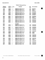
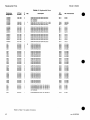
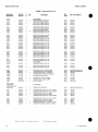
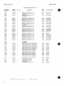
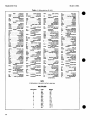
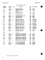
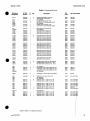
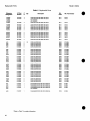
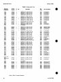
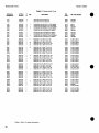
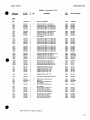
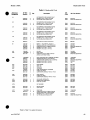
Table 5. Replaceable Parts
Reference
Designation
HP Part
Number
C
D
A3C51
A3C53
A3C54
A3C55
0160-3324
0160-4787
0160-3324
0160-4822
7
8
7
2
A3CS6
A3C57-200
A3C201
A3C202
A3C203
0160-4389
6
0180-0229
0180-0291
0160-4801
7
3
7
A3C204
A3C205
A3C206
A3C207
A3C208
01604801
0180-1746
0180-1746
0180-1746
0180-1746
A3C209
A3C210
A3C211
A3C212
A3C213
Q ^
Mfr.
Code
Description
Mfr. Part Nun
CAPACITOR-FXD
CAPACITOR-FXD
CAPACITOR-FXD
CAPACITOR-FXD
1UF+-5% 100VDC MET-POLYC
22PF+-5% 100VDC CER 0+-30
1UF +-5% 100VDC MET-POLYC
1000PF+-5% 100VDC CER
28480
28480
28480
28480
0160-3324
0160-4787
0160-3324
0160-4822
CAPACITOR-FXD
NOT ASSIGNED
CAPACITOR-FXD
CAPACITOR-FXD
CAPACITOR-FXD
100PF +-5PF 200VDC CER
28480
0160-4389
33UF+-10% 10VDCTA
1UF+-10%35VDCTA
100PF+-5% 100VDC CER
56289
56269
28480
150D336X9010B2
150D105X9035A2
01604801
7
5
S
5
5
CAPACITOR-FXD
CAPACITOR-FXD
CAPACITOR-FXD
CAPACITOR-FXD
CAPACITOR-FXD
100PF +-5% 100VDC CER
15UF+-10%20VDC TA
15UF+-10% 20VDC TA
15UF+-10% 20VDC TA
15UF+-10% 20VDC TA
28480
56289
56289
56289
56289
0160-4801
150D156X9020B2
150D156X9020B2
150D156X9020B2
150D158X9020B2
0180-1746
0180-1746
0180-1746
0180-1746
0180-1746
5
5
5
5
5
CAPACITOR-FXD
CAPACITOR-FXD
CAPACITOR-FXD
CAPACITOR-FXD
CAPACITOR-FXD
15UF+-10%20VDCTA
15UF+-10%20VDCTA
15UF+-10%20VDCTA
15UF+-10% 20VDC TA
15UF+-10% 20VDC TA
56289
56289
56289
56289
56289
150D156X9020B2
150D156X9020B2
150D156X9020B2
150D156X9020B2
150D156X9020B2
A3C214
A3C215
A3C216
A3C217
A3C218
0180-1746
0180-1746
0180-1746
0180-1746
0180-1746
5
5
5
5
5
CAPACITOR-FXD
CAPACITOR-FXD
CAPACITOR-FXD
CAPACITOR-FXD
CAPACITOR-FXD
15UF+-10% 20VDC TA
15UF+-10%20VDCTA
15UF+-10% 20VDCTA
15UF+-10% 20VDCTA
15UF+-10%20VDCTA
56289
56289
56289
56289
56289
150D156X9020B2
150D156X9020B2
150D156X9020B2
150D156X9020B2
150D156X9020B2
A3C219
A3C220
A3C221
A3C222
A3C223
0180-1746
0180-1746
0180-1746
0180-1746
0180-1746
5
S
5
5
5
CAPACITOR-FXD
CAPACITOR-FXD
CAPACITOR-FXD
CAPACITOR-FXD
CAPACITOR-FXD
15UF+-10% 20VDC TA
15UF+-10% 20VDC TA
15UF+-10% 20VDCTA
15UF+-10%20VDCTA
15UF+-10%20VDCTA
56289
56289
56289
56289
56289
150D156X9020B2
150D156X9020B2
150D156X9020B2
150D158X9020B2
150D156X9020B2
A3C224
A3C225
A3C226
0180-1746
0180-2207
0180-2667
5
5
1
CAPACITOR-FXD 15UF+-10%20VDCTA
CAPACITOR-FXD 100UF+-10% 10VDCTA
CAPACITOR-FXD 150UF+-10%20VDCTA
56289
56289
56289
150D156X9020B2
150D107X9010R2
152D157X9020S2
A3CR1
A3CR2
A3CR3
A3CR4-7
A3CR8
1901-0518
1901-0518
1901-0518
8
8
8
3
28480
28480
28480
1901-0518
1901-0518
1901-0518
1901-0418
7
4
DIODE-SM SIQ SCHOTTKY
DIODE-SM SIQ SCHOTTKY
DIODE-SM SIQ SCHOTTKY
NOT ASSIGNED
DIODE-PWR RECT400V 1.5A
28480
1901-0418
A3CR9
A3CR10
A3CR11
A3CR12
A3CR13
1901-0418
1901-0050
1901-0050
1901-0418
1901-0418
7
3
3
7
7
DIODE-PWR RECT 400V 1.5A
DIODE-SWITCHING 80V 200MA 2NS DO-35
DIODE-SWITCHING 80V 2O0MA 2NS DO-35
DIODE-PWR RECT4O0V 1.5A
DIODE-PWR RECT 400V 1.5A
28480
9N171
9N171
28480
28480
1901-0418
1N4150
1N4150
1901-0418
1901-0418
A3CR14
A3CR15
A3CR16-200
A3CR201
1901-0050
1901-0050
3
3
9N171
9N171
1N4150
1N4150
1901-0050
3
DIODE-SWITCHING 80V 200MA 2NS DO-35
DIODE-SWITCHING 80V 200MA 2NS DO-35
NOT ASSIGNED
DIODE-SWITCHING 80V 200MA 2NS DO-35
9N171
1N4150
A3F1
A3F2
A3F3
A3F4
2110-0757
21104757
2110-0757
2110-0757
1
1
1
1
FUSE-SUBMINIATURE
FUSE-SUBMINIATURE
FUSE-SUBMINIATURE
FUSE-SUBMINIATURE
75915
75915
75915
75915
251.062
251.062
251.062
251.062
3
6
8
2
1
9
0.63A 125V
0.63A 125V
0.63A 125V
0.63A 125V
.28X.095 UL
.28X.095 UL
.28X.095 UL
.28X.095 UL
f Refer to Table 7 for .update information.
rev.
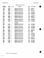
Model 11848A
Replaceable Parts
c
Mir.
Code
Mfr. Part
1.14-MM-BSC-SZ SQ
1.14-MM-BSC-SZ SO
1.14-MM-BSC-SZ SO
1.14-MM-BSC-SZ SO
1.14-MM-BSC-SZ SQ
28480
28480
28480
28480
28480
1251-0600
1251-0600
1251-0600
1251-0600
1251-0600
CONT PIN
CONT PIN
CONT PIN
CONT PIN
CONT PIN
1.14-MM-BSC-SZ SO
1.14-MM-BSC-SZ SQ
1.14-MM-BSC-SZ SQ
1.14-MM-BSC-SZ SQ
1.14-MM-BSC-SZ SQ
28480
28480
28480
28480
28480
1251-0600
1251-0600
1251-0600
1251-0600
1251-0600
CONNECTOR-SQL
CONNECTOR-SQL
CONNECTOR-SGL
CONNECTOR-SOL
CONNECTOR-SQL
CONT
CONT
CONT
CONT
CONT
PIN
PIN
PIN
PIN
PIN
1.14-MM-BSC-SZ SO
1.14-MM-BSC-SZ SO
1.14-MM-BSC-SZ SO
1.14-MM-BSC-SZ SQ
1.14-MM-BSC-SZ SQ
28480
28480
28480
28480
28480
1251-0600
1251-0600
1261-0600
1251-0600
1251-0600
0
0
0
0
0
CONNECTOR-SQL
CONNECTOR-SQL
CONNECTOR-SQL
CONNECTOR-SQL
CONNECTOR-SQL
CONT
CONT
CONT
CONT
CONT
PIN
PIN
PIN
PIN
PIN
1.14-MM-BSC-SZ
1.14-MM-BSC-SZ
1.14-MM-BSCSZ
1.14-MM-BSC-SZ
1.14-MM-BSC-SZ
SO
SQ
SQ
SQ
SO
28480
28480
28480
28480
28480
1261-0600
1251-0600
1251-0600
1251-0600
1251-0600
1251-0600
1251-0600
1251-0600
1261-0600
1251-0600
0
0
0
0
0
CONNECTOR-SQL
CONNECTORSGL
CONNECTOR-SGL
CONNECTOR-SQL
CONNECTOR-SQL
CONT
CONT
CONT
CONT
CONT
PIN
PIN
PIN
PIN
PIN
1.14-MM-BSC-SZ SQ
1.14-MM-BSC-SZ SQ
1.14-MM-BSC-SZ SQ
1.14-MM-BSC-SZ SO
1.14-MM-BSC-SZ SQ
28480
28480
28480
28480
28480
1251-0600
1251-0600
1251-0600
12514600
12514600
A3TP36
A3TP37
A3TP38
A3TP39
A3TP40
1251-0600
1251-0600
1251-0600
1251-0600
1251-0600
0
0
0
0
0
CONNECTORSGL
CONNECTORSGL
CONNECTORSGL
CONNECTOR-SGL
CONNECTOR-SGL
CONT
CONT
CONT
CONT
CONT
PIN
PIN
PIN
PIN
PIN
1.144HM-BSC-SZ SQ
1.14-MM-BSC-SZ SO
1.14-MM-BSC-SZ SQ
1.14-MM-BSC-SZ SQ
1.14-MM-BSC-SZ SQ
28480
28480
28480
26480
28480
12514600
12514600
12614600
12514600
12514600
A3TP41
A3TP42
A3TP43
A3TP44
A3TP45
1261-0600
1251-0600
1251-0600
1251-0600
1251-0600
0
0
0
0
0
CONNECTORSGL
CONNECTOR-SGL
CONNECTORSGL
CONNECTORSGL
CONNECTORSGL
CONT PIN
CONT PIN
CONT PIN
CONT PIN
CONT PIN
1.14-MM-BSC-SZ SQ
1.14-MM-BSC-SZ SQ
1.14-MM-BSC-SZ SO
1.14-MM-BSCSZ SQ
1.14-MM-BSCSZ SQ
28480
284S0
28480
28480
28480
12514600
12514600
12614600
12514600
12514600
A3TP46 A3TP47
A3TP48-200
A3TP201
A3TP202
1251-0600
1251-0600
0
0
CONT PIN 1.14-MM-BSCSZ SQ
CONT PIN 1.14-MM-SSC-SZ SQ
28480
28480
12514600
12514600
1251-0600
1251-0600
0
0
CONNECTORSGL
CONNECTORSGL
NOT ASSIGNED
CONNECTORSGL
CONNECTORSGL
CONT PIN 1.14-MM-BSCSZ SQ
CONT PIN 1.14-MM-BSCSZ SQ
28480
28480
12514600
12514600
A3TP203
A3TP204
A3TP205
A3TP206
A3TP207
1261-0600
1251-0600
1251-0600
1251-0600
1251-0600
0
0
0
0
0
CONNECTOR-SGL
CONNECTORSGL
CONNECTORSGL
CONNECTORSGL
CONNECTORSGL
CONT PIN
CONT PIN
CONT PIN
CONT PIN
CONT PIN
28480
28480
28480
28480
26460
12514600
12614600
12514600
12514600
12514600
A3U1
1620-0270
12054095
7
0
IC WIDEBAND AMPL VID TO-100 PKG
HEAT SINKSGL TCW/T039-CS
NOT ASSIGNED
NOT ASSIGNED
IC COMPARATOR PRCN 8-DIP-P PKG
07263
30161
UA733HC.
3225B
27014
LM311N
IC COMPARATOR PRCN 8-DIP-P PKG
IC OP AMP LOW-BIAS+HMPD 8-DIP-P PKG
IC OP AMP PRCN 8-OIP-C PKG
IC OP AMP LOW-NOISE DUAL 8-DIP-C PKG
IC OP AMP LOW-BIAS-H-IMPD 6-OIP-P PKG
27014
27014
06665
16324
27014
LM311N
LF356N
OP-27GZ
NE5532AFE
LF356N
Reference
designation
HP Part
Number
D
A3TP11
A3TP12
A3TP13
A3TP14
A3TP15
1251-0600
1251-0600
1251-0600
1251-0600
1251-0600
0
0
0
0
0
CONNECTOR-SQL
CONNECTOR-SQL
CONNECTOR-SQL
CONNECTOR-SQL
CONNECTORSGL
CONT PIN
CONT PIN
CONT PIN
CONT PIN
CONT PIN
A3TP16
A3TP17
A3TP18
A3TP19
A3TP20
1251-0600
1261-0600
1251-0600
1251-0600
1251-0600
0
0
0
0
0
CONNECTORSGL
CONNECTOR-SQL
CONNECTOR-SQL
CONNECTOR-SQL
CONNECTOR-SQL
A3TP21
A3TP22
A3TP23
A3TP24
A3TP25
1251-0600
1261-0600
1251-0600
1251-0600
1261-0600
0
0
0
0
0
A3TP26
A3TP27
A3TP28
A3TP29
A3TP30
1251-0600
1251-0600
1251-0600
1261-0600
1251-0600
A3TP31
A3TP32
A3TP33
A3TP34
A3TP36
Qty.
A3U2
A3 US
A3U4
A3U5
A3U6
A3U7
A3UB
A3U9
18264065
1826-2005
1826-1048
16264716
1826-2005
0
2
2
8
2
11
1
3
fRefer to Section 7 for update information.
rev.02NOV92
Description
1 14-MM-BSC-SZ SQ
1.14-MM-BSCSZ SQ
1.14-MM-BSCSZ SQ
1.14-MM-BSCSZ SQ
1.14-MM-BSCSZ SQ
"Factory Selected Component (Refer to Section 5).
A Errata part change.
37
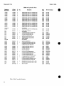
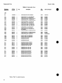
Replaceable Parts
Reference
Designation
Model 11848A
c
HP Part
Number
D
A3U10
A3U11
A3U12
A3U13
A3U14
1826-2005
1826-2005
1826-2005
1826-2005
1826-0783
2
2
2
2
9
A3U15
A3U16
A3U17
A3U18
A3U19
1820-1422
1826-1482
1626-2005
1826-2005
1826-2005
a
9
2
2
2
A3U20
A3U21
A3U22
A3U23
A3U24
1826-2005
1826-2005
1826-1150
18260718
1826-0606
2
2
6
8
S
A3U25
A3U26
A3U27
A3U28
A3U29
18264606
1826-0606
18264606
1826-0606
1626-0606
A3U30
A3U31
A3U32
A3U33
A3U34-200
Mfr.
Code
Mfr. Part N
LCW-BIAS-HJMPD 8-OIP-P PKQ
LOW-BIASJ4JMPD 8-OIP-P PKQ
LOW-BIAS-H-IMPD 8-DIP-P PKQ
LOW-BIAS-HJMPD 8-OIP-P PKQ
LOW-NOISE 8-DIP-C PKQ
27014
27014
27014
27014
52063
LF356N
LF356N
LF356N
LF356N
XR5S34ACN
IC MV TTL LS MON05TBL RETRIQ
IC OP AMP PRCN 8-DIP-C PKQ
IC OP AMP LOW-BIAS-HJMPD 8-OIP-P PKQ
IC OP AMP ICW-SIAS-H-IMPD 8-DIP-P PKQ
IC OP AMP LOW-BIAS-HJMPD 6-DIP-P PKQ
01295
06665
27014
27014
27014
SN74LS122N
OP-16EZ
LF356N
LF356N
LF3S6N
IC
IC
IC
IC
IC
OP AMP LOW-BIAS-HJMPD 6-DIP-P PKQ
OP AMP LOW-BIAS-HJMPD 8-DIP-P PKQ
OP AMP INSTM DUAL 14-DIP-C PKQ
OP AMP LOW-NOISE DUAL 6-OIP-C PKQ
SWITCH ANLQ QUAD 16-DIP-C PKQ
27014
27014
06665
18324
178S6
LF356N
LF356N
OP-227GY
NE5532AFE
DQ201BK
6
6
5
5
6
IC
IC
IC
IC
IC
SWITCH ANLQ QUAD
SWITCH ANLQ QUAD
SWITCH ANLQ QUAD
SWITCH ANLQ QUAD
SWITCH ANLQ QUAD
18-DIP-C PKQ
16-DIP-C PKQ
16-DIP-C PKQ
16-OIP-C PKQ
16-DIP-C PKQ
17856
17856
17856
17856
17856
DQ201BK
DQ201BK
DQ201BK
DQ201BK
DQ201BK
18264606
18264606
16264606
18264606
6
5
6
5
IC SWITCH ANLQ
IC SWITCH ANLQ
IC SWITCH ANLQ
IC SWITCH ANLQ
NOT ASSIGNED
16-DIP-C
16-DIP-C
16-DIP-C
160IP-C
17856
17856
17856
17856
DG201BK
DG201BK
DQ201BK
DQ201BK
A3U201
A3U202
A3U203
A3U204
A3U205
1820-1730
1820-1730
1820-1730
1820-1730
1820-1216
6
6
6
6
3
IC
IC
IC
IC
IC
COM
COM
COM
COM
01295
01295
01295
01295
01295
SN74LS273N
SN74LS273N
SN74LS273N
SN74LS273N
SN74LS138N
A3U206
A3U207
A3U20S
A3U20S
A3U210
1820-1281
1820-1216
18264188
18264188
18264766
2
3
8
8
3
1
2
IC DCDR TTL LS 2-TO-4-UNE DUAL
IC DCDR TTL LS 3-T04-UNE 3JNP
D/A 8-BIT 16-CEPdlP BPLR
D/A 8-BIT 16<!ERDIP BPLR
IC OP AMP LOW-BIAS-t+JMPD DUAL 8-DIP-C
01295
01295
04713
04713
01295
SN74LS139AN
SN74LS138N
MC1408L-8
MC1406L-8
TL072ACJQ
A3U211
A3U212
A3U213
A3U214
A3U215
1820-1416
1820-1281
1820-1416
1820-1281
1820-1201
IC
IC
IC
IC
IC
0129S
01295
01295
01295
01295
SN74LS14N
SN74LS139AN
SN74LS14N
SN74LS139AN
SN74LS08N
Description
A H
UI]
7
1
1
1
14
3
&
2
•6
2
8
IC OP AMP
IC OP AMP
IC OP AMP
IC OP AMP
IC OP AMP
QUAD
QUAD
QUAD
QUAD
PKQ
PKQ
PKQ
PKQ
FF TTL LS D-TYPE POS-EDGE-TRIG
FF TTL LS D-TYPE POS-EDGE-TRIG
FF TTL LS D-TYPE POS-EDGE-TRIG
FF TTL LS D-TYPE PCS-EDGE-TRIG
DCDR TTL LS 3-TOJJ-UNE 3JNP
SCHMITT-TRIG TTL LS INV HEX i-INP
DCDR TTL LS 2-TO44JNE DUAL
SCHMITT-TRIG TTL LS INV HEX 1-INP
DCDR TTL LS 2-TO-WJNE DUAL
GATE TTL LS AND QUAD 2-INP
16UAT01647A
A3VR1
1648A AND ABOVE
A3VR1
10024680
7
1
DIODE-ZNR 1N827 6.2V 6 * DO-7 PD . .4W
24046
1N827
A3VR2
A3VR3
A3VR4
A3VR5
18024846
18024946
18024946
18024946
6
6
4
DIOOE-ZNR
DIODE-ZNR
DIOOE-ZNR
DIODE-ZNR
26480
28480
28480
28480
19024946
19024946.
19024946
19024946
NOT ASSIGNED
e
8
fRefer to Section 7 for update information.
38
3.3V
3.3V
3.3V
3.3V
5% DO-35
5% DO-35
6% DO-35
5% DO-35
PD PD PD PD -
.4W TC ,4W TC .4W TC .4W TC -
-.039%
-.039%
-.039<K>
-.039%
•Factory Selected Component (Refer to Section 5).
A Errata part change.
rev.02NOV92
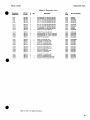
Model 11848A
Replaceable Parts
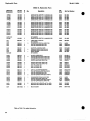
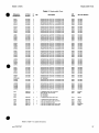
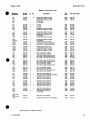
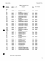
Table 6-3. Replaceable Parts
Reference
Designation
c Qty.
HP Part
Number
D
Description
MIT.
Code
Mir. Part Nur
66289
56289
28480
28480
28480
160D226X9035R2
150D226X9035R2
0160-0168
0160-0168
0160-0168
CAPACfTOR-FXD 1000PF +-6% 100VDC CER
CAPACITOR-FXD 1UF + -10% 50VDC CER
CAPACITOR-FXD 1UF + -10% S0VDC CER
CAPAOTOR-FXD47PF + -6% 100VDC CER0 + -30
CAPACITOFtFXD 51PF +-5% 100VDC CER 0 + -30
28480
28480
28480
28480
28480
0160-4822
0160-4535
0160-4535
0160-4805
0160-5348
8
7
7
8
4
CAPACrTOR-FXD
CAPACITOFtFXD
CAPACITOR-FXD
CAPACrTOR-FXD
CAPACITOR-FXD
22PF +-64* 100VDC CER 0 + -30
100PF + -6% 100VDC CER
100PF +-6% 100VDC CER
22PF +-6% 100VDC CER 0 +-30
1UF +-10<M> 50VDC CER
28480
28480
28480
28480
28480
0160-4787
0160-4801
0160-4801
0160-4787
0160-4535
0160-4535
0160-4535
0160-6616
0160-4535
4
4
6
4
CAPACrTOR-FXD
CAPACITOR-FXD
CAPACITOR-FXD
CAPACrTORFXD
1UF + -10% 50VDC CER
1UF + -10% 50VDC CER
6800PF +-10% 100VDC CER
1UF +-10% 50VDC CER
28480
28480
28480
0160-4535
0160-4535
0160-6616
28480
0160-4535
A4CR1
A4CR2
A4CR3
A4CR4
A4CR5
1901-1098
1901-1098
1901-1098
1901-1098
1901-1098
3
3
3
3
3
DIODE-SWITCHING
DIODE-SWITCHING
DIODE-SWITCHING
DIODE-SWITCHING
DIODE-SWITCHING
80V 200MA 2NS
80V 200MA 2NS
80V 200MA 2NS
80V 200MA 2NS
80V 200MA 2NS
DO-35
D035
DO-35
DO-35
DO-35
9N171
9N171
9N171
9N171
9N171
1N4150
1N4150
1N4150
1N4150
1N4150
A4CR6
A4CR7
A4CR8
A4CR9
A4CR10
1901-1098
1901-1098
1901-1098
1901-1098
1901-1098
3
3
3
3
3
DIODE-SWITCHING
DIODE-SWITCHING
DIODE-SWITCHING
DIODE-SWITCHING
DIODE-SWITCHING
80V
80V
80V
80V
80V
2NS
2NS
2NS
2NS
2NS
DO-35
D035
DO-35
DO-35
D035
9N171
9N171
9N171
9N171
9N171
1N4150
1N4150
1N4150
1N4150
1N4150
A4CR11
MCR12
A4CR13
A4CR14
A4CR15
1901-1098
1901-1098
1901-1098
1901-1098
1901-1098
3
3
3
3
3
DIODE-SWITCHING
DIODE-SWITCHING
DIODE-SWITCHING
DIODE-SWITCHING
DIODE-SWITCHING
80V 200MA 2NS
80V 200MA 2NS
80V 200MA 2NS
80V 200MA 2NS
80V 200MA 2NS
D035
DO-35
DO-35
DO-35
DO-35
9N171
9N171
9N171
9N171
9N171
1N4150
1N4150
1N4150
1N4150
1N4150
A4CR16
A4CR17
A4CR18
A4CR19
A4CR20
1901-1098
1901-1098
1901-1098
1901-1098
1901-1098
3
3
3
3"
3
DIODE-SWITCHING
DIODE-SWITCHING
DIODE-SWITCHING
DIODE-SWITCHING
DIODE-SWITCHING
80V
80V
80V
80V
80V
DO-35
DO-35
DO05
DO-35
DO-35
9N171
9N171
9N171
9N171
9N171
1N41S0
1N4150
1N4150
1N4150
1N4150
A4CR21
A4CR22
A4CR23
A4CR24
A4CR25
1901-1098
3
DIODE-SWITCHING 80V 200MA 2NS DO-35
9N171
1901-1098
1901-1098
3
3
DIODE-SWITCHING 80V 200MA 2NS DO<35
DIODE-SWITCHING 80V 200MA 2NS DO-35
9N171
9N171
1N4150
1N4150
A4CR26
A4CR27
1901-1098
1901-1098
3
3
DIODE-SWITCHING 80V 200MA 2NS DO-35
DIODE-SWITCHING 80V 200MA 2NS DO-35
9N171
9N171
1N4150
1N4150
A4CR28
A4CR29
A4CR30-200
A4CR201
A4CR202
1901-1098
1901-1098
3
3
80V 200MA 2NS DO-35
80V 200MA 2NS DO-35
9N171
9N171
1N4150
1N4150
1901-1098
1901-1098
3
3
DIODE-SWITCHING
DIODE-SWITCHING
NOT ASSIGNED
DIODE-SWITCHING
DIODE-SWITCHING
80V 200MA 2NS DO-35
80V 200MA 2NS DO-35
9N171
9N171
1N4150
1N4150
A4C213
A4C214
A4C215
A4C216
A4C217
0180-1794
0180-1794
0160-0168
0160-0168
0160-0168
A4C218
A4C219
A4C220
A4C221
A4C222
.
3
3
1
1
1
CAPACITOR-FXD
CAPACITOFtFXD
CAPACITOR-FXD
CAPACrTOR-FXD
CAPACITOR-FXD
0160-4822
0160-4535
0160-4535
0160-4805
0160-5348
2
4
4
1
9
A4C223
A4C224
A4C225
A4C226
A4C227
0160-4787
0160-4801
0160-4801
0160-4787
0160-4535
A4C228
A4C229
A4C230*
A4C231
JRefer lo Section 7 for update information.
rev.0lAUG92
22UF+ -104* 35VDC TA
22UF+-10% 35VDC TA
.1UF + -10% 200VDC POLYE
.1UF + -10% 200VDC POLYE
.1UF +-10% 200VDC POLYE
200MA
200MA
200MA
200MA
200MA
200MA
200MA
200MA
200MA
200MA
2NS
2NS
2NS
2NS
2NS
"Factory Selected Component (Refer to Section 5).
A En.ita part change.
41
Replaceable Parts
Model 11848 A
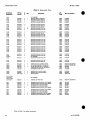
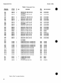
Table 5. Replaceable Parts
Reference
Designation
HP Part
Number
c
Description
Mfr.
Code
DIODE-SWITCHING 80V 200MA 2NS DO-35
DIODE-SWITCHING 80V 200MA 2NS DO-35
NOT ASSIGNED
NOT ASSIGNED
DIODE-ZNR 5.6V 5% 0O-35 PD=.4W TC=+.046%
DIODE-ZNR 5.6V 5% DO-35 PD=.4W TC=+.046%
DIODE-SWITCHING 80V 200MA 2NS DO-35
9N171
9N171
1N4150
1N4150
28480
28480
9N171
19020952
19020952
1N4150
Qty.
D
Mfr. Pat
A4CR203
A4CR204
A4CR205
A4CR206
A4CR205
A4CR206
A4CR207
1901-1098
1901-1098
3
3
19020952
19020952
1901-1098
6
6
3
A4CR208
A4CR209
A4CR210
A4CR211
A4CR212
1901-1098
1901-1098
1901-1098
1901-1098
1901-1098
3
3
3
3
3
DIODE-SWITCHING 60V 200MA 2NS DO-35
DIODE-SWITCHING 80V 200MA 2NS DO-35
DtODE-SWTTCHING 80V 200MA 2NS DO-35
DtOOE-SWITCHING 80V 200MA 2NS DO-35
DIODE-SWITCHING 80V 200MA 2NS DO-35
9N171
9N171
9N171
9N171
9N171
1N4150
1N4150
1N4150
1N4150
1N4150
A4CR213
A4CR214
A4CR215
A4CR216
A4CR217
1901-1098
1901-1098
1601-1098
1901-1098
1901-1098
3
3
3
3
3
DIODE-SWrrCHING 80V 200MA 2NS DO-35
DIODE-SWITCHING 80V 200MA 2NS DO-35
DIODE-SWITCHING 80V 200MA 2NS DO-35
DIODE-SWITCHING 80V 200MA 2NS DO-35
DtOOE-SWITCHING 80V 200MA 2NS DO-35
9N171
9N171
9N171
9N171
9N171
1N4150
1N41S0
1N4150
1N4150
1N4150
A4CR218
1901-1098
3
DtOOE-SWITCHING 80V 200MA 2NS DO-35
9N171
1N4150
A4E1
A4E2
A4E3
A4E4
A4E5
91700894
91700894
61700894
91700894
91700894
0
0
0
0
0
CORE-SHIELDING BEAD
CORE-SHIELDING BEAD
CORE-SHIELDING BEAD
CORE-SHIELDING BEAD
CORE-SHIELDING BEAD
28480
28460
28480
28480
28480
91700894
91700894
91700894
91700894
91700894
A4E6
A4E7
A4E8
A4E9
A4E10
91700894
91700894
91700894
91700894
91700894
0
0
0
0
0
CORE-SHIELDING BEAD
CORE-SHIELDING BEAD
CORE-SHIELDING BEAD
CORE-SHIELDING BEAD
CORE-SHIELDING BEAD
26480
28480
28480
28480
28480
91700894
91700894
91700894
91700894
91700894
A4E11
A4E12
A4E13
A4E14
A4E15
91700894
91700894
91700894
91700894
91700894
0
0
0
0
0
CORE-SHIELDING BEAD
CORE-SHIELDING BEAD
CORE-SHIELDING BEAD
CORE-SHIELDING BEAD
CORE-SHIELDING BEAD
28480
28480
28480
28480
28480
91700894
61700894
91700894
91700894
91700894
A4E16
A4E17
A4E18
A4E19
A4E20
91700894
91700894
91700894
91700894
91700894
0
0
0
0
0
CORE-SHIELDING BEAD
CORE-SHIELDING BEAD
CORE-SHIELDING BEAD
CORE-SHIELDING BEAD
CORE-SHIELDING BEAD
28480
26480
28480
28480
28480
91700894
91700894
9170-0894
91700894
91700894
A4E21
A4E22
A4E23
A4E24
A4E25
91700894
9170-0894
91700894
91700894
61700894
0
0
0
0
0
CORE-SHIELDING BEAD
CORE-SHIELDING BEAD
CORE-SHIELDING BEAD
CORE-SHIELDING BEAD
CORE-SHIELDING BEAD
28480
28480
28480
28480
28480
91700894
91700894
91700894
91700894
91700894
A4E26
A4E27
A4E28
9170-0894
91700894
91700894
0
0
0
CORE-SHIELDING BEAD
CORE-SHIELDING BEAD
CORE-SHIELDING BEAD
26480
28480
28480
91700894
91700894
6170O894
A4F1
A4F2
A4F3
A4F4
A4F5
21100757
21100757
21100757
21100757
1
1
1
1
FUSE-SUBMINIATURE 0.63A
FUSE-SUBMINIATURE 0.63A
FUSE-SUBMINIATURE 0.63A
FUSE-SUBMINIATURE 0.63A
NOT ASSIGNED
.28X095 UL
.28X095 UL
.28X095 UL
.28X.095 UL
75915
75915
75915
75915
251.062
251.062
251.062
251.062
A4F6
21100757
1
FUSE-SUBMINIATURE 0.63A 125V .28X.095 UL
75915
251.062
2
28
125V
125V
125V
125V
t Refer to Table 7 for update information.
42
rev.2lSEP89
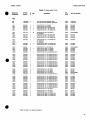
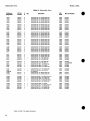
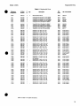
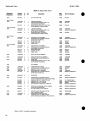
Replaceable Parts
Model 11848A
Table 63. Replaceable Parts
Reference
Designation
HP Part
Number
c
Description
Qty
D
Mfr. Part Numtx
03888
03888
03888
03888
03888
PME55-1/8-T0-21R5-F
PME5S-1/B-T0-21R5-F
PME55-1/8-T0-21R6-F
PME55-1/8-T0-21R5-F
PME55-1/8-TO-21R5-F
A4R96
A4R97
A4R98
A4R99
A4R100
0698-3430
0698-3430
0698-3430
0698-3430
0698-3430
6
5
5
5
6
RESISTOR21.6
RESISTOR21.5
RESISTOR21.5
RESISTOR 21.5
RESISTOR 21.5
A4R101
MR102
MR103
A4R104
A4R105
0698-3430
0757-0461
0767-0461
0698-3430
0698-3430
5
2
2
5
6
RESISTOR 21.5 19* .125W F T C - 0 + -100
RESISTOR 68.1K 19* .125W F T C - 0 + -100
RESISTOR 68.1K 19* .125W F T C - 0 + -100
RESISTOR21.6 19* .126W F T C - 0 + -100
RESISTOR21.5 14t> .125W F T C - 0 + -100
03888
24S46
24548
03888
03888
PME55-1/8-T0-21R5-F
CT4-1/8-T0-6812-F
CT4-1/8-T0-6812-F
PME55-1/8-T0-21FS-F
PME55-1/8-T0-21R5-F
MR106
MR107
A4R108
MR109
A4R110
0757-0442
0767-0199
0757-0394
0767-0394
0757-0394
9
3
0
0
0
RESISTOR 10K 1 * .12SW F T C - 0 + -100
RESISTOR 21.5K 19* .125W F T C - 0 + -100
RESISTOR 51.1 1 9 * . 1 2 5 W F T C - 0 + -100
RESISTOR 61.1 1 9 4 . 1 2 5 W F T C - 0 + -100
RESISTOR 51.1 1 9 * . 1 2 5 W F T C - 0 + -100
24546
24546
24546
24546
24546
CT4-1/8-TO-1002-F
CT4-1/8-T0-2152-F
CT4-1/8-T0-61R1-F
CT4-1/8-T0-61R1-F
CT4-1/8-T0-51R1-F
A4R111
A4R112
A4R113-119
A4R120
A4R121
0757-0394
0698-3447
0
4
24546
24546
CT4-1/8-T0-51R1-F
CT4-1/8-T0-422R-F
0698-3150
0757-0279
6
0
RESISTOR61.1 19* . 1 2 5 W F T C 0 + -100
RESISTOR422 19(> .125W F T C - 0 + -100
NOT ASSIGNED
RESISTOR 2.37K 1 % .125W F TC - 0 + -100
RESISTOR 3.16K 1 9 * . 1 2 5 W F T C - 0 + -100
24546
24546
CT4-1/8-T0-2371-F
CT4-1/8-T0-3161-F
A4R122
A4R123
A4R124
A4R125
A4R126
0757-0338
2
24546
NA5-1/4-TO-1001-F
0757-0394
0698-3150
0757-0394
0
6
0
RESISTOR 1K 19* .25W F T C - 0 + -100
NOT ASSIGNED
RESISTOR51.1 1 9 * . 1 2 5 W F T C - 0 + -100
RESISTOR 2.37K 1 % .125W F T C - 0 + -100
RESISTOR51.1 1 9 t > . 1 2 5 W F T C 0 + -100
24546
24546
24546
CT4-1/8-T0-61R1-F
CT4-1/8-T0-2371-F
CT4-1/8-T0-51R1-F
mil
Mir.
Code
0757-0394
0698-3150
0757-0316
0
6
6
24546
24546
28480
CT4-1/8-T0-51R1-F
CT4-1/8-T0-2371-F
0757-0316
0698-3443
0
RESISTOR51.1 191) .125W F T C - 0 + -100
RESISTOR 2.37K 19* .125W F T C - 0 + -100
RESISTOR425 19* .125W F T C - 0 + -100
NOT ASSIGNED
FIESISTOR287 19* .125W F T C - 0 + -100
24546
CT4-1/8-T0-2870-F
A4R202
A4R203
MR204
A4R205
A4R206
0757-0401
0698-4386
0698-4400
0698-3438
0698-3486
0
2
1
3
1
RESISTOR 100 19* .125W F T C - 0 + -100
RESISTOR 59 19*.125W F T C - 0 + -100
RESISTOR 93.1 1 9 6 . 1 2 5 W F T C - 0 + -100
RESISTOR 147 19* .125W F T C . 0 + -100
FIESISTOR232 19* .125W F T C . 0 + -100
24546
24546
24546
24546
24546
CT4-1/8-TO-101-F
CT4-1/8-T0-59R0-F
CT4-1/8-T0-83R1-F
CT4-1/8-TO-147R-F
CT4-1/8-T0-232R-F
A4R207
A4R208
A4R209
A4R210
A4R211
0757-0412
0698-4458
0698-4465
0757-0442
0698-0082
3
9
8'
9
7
RESISTOR 365 19* .12SW F T C 0 + -100
RESISTOR 590 1 9 * . 1 2 5 W F T C - 0 + -100
RESISTOR 931 1 9 * . 1 2 5 W F T C - 0 + -100
RESISTOR 10K 19* .125W F T C - 0 + -100
RESISTOR464 19* .125W F T C - 0 + -100
24546
24546
24546
24546
24546
CT4-1/8-T0-365R-F
CT4-1/8-TO-590R-F
CT4-1/8-T0-931R-F
CT4-1/8-T0-1002-F
CT4-1/8-T0-4640-F
A4R212
A4R213
A4R214
A4R215
A4R216
0757-0442
0698-0083
0757-0161
0698-4413
0698-3440
9
8
9
6
7
RESISTOR
RESISTOR
RESISTOR
RESISTOR
RESISTOR
24546
24546
24546
24546
24546
CT4-1/8-TO-1002-F
CT4-1/8-TO-1961-F
CT4-1/8-T0-604R-F
CT4-1/8-T0-154R-F
CT4-1/8-TO-196R-F
A4R217
A4R218
A4R219
A4R220
A4R221
0698-4421
0698-4449
0757-0413
0698-3178
0757-0418
6
8 •
4
8
S
24546
24546
24546
24546
24546
CT4-1/8-T0-249R-F
CT4-1/8-T0-309R-F
CT4-1/8-T0-392R-F
CT4-1/8-T0-487R-F
CT4-1/6-T0-619R-F
tRefer to Section 7 for u p d a t e information.
rev.01AUG92
4
1
1
1
1
1
1
1
1
1
1
1
1
1
19* -12SW
1 % .125W
19* .125W
1 * .125W
19* .125W
FTC-0
FTC-0
FTC-0
FTC-0
FTC-0
+ -100
+ -100
+ -100
+ -100
+ -100
10K 19* .125W F T C . 0 + -100
1.96K 19* .125W F T C - 0 + -100
604 19* .125W F T C - 0 + -100
154 19* .125W F T C - 0 + -100
196 19* .125W F T C - 0 + -100
RESISTOR 249
RESISTOR 309
RESISTOR392
RESISTOR487
RESISTOR 619
19*
19*
19*
19*
19*
.125W
.125W
.125W
.125W
.125W
FTC-0
FTC-0
FTC-0
FTC-0
FTC-0
+ -100
+ -100
+ -100
+ -100
+ -100
"Factory Selected C o m p o n e n t (Refer to Section 6).
A Errata p a n change.
47
Eeplaceable Parts
Model 11848A
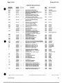
Table 6-3. Replaceable Parts
Reference
Designation
HP Part
Number
D
A4R222
A4R223
MR224
A4R225
A4R226
0757-0273
0698-8827
0698-3492
0698-4643
0698-3157
4
4
8
3
3
A4R227
A4R228
A4R229
A4R230
A4R231
0757-0442
0698-3279
0698-3150
0698-3223
0757-0420
9
0
A4R232
MR233
A4R234
A4R235
A4R236
MR237
MR238
A4R239
A4R240
A4R241
Mfr.
Code
Mfr. Part Num
RESISTOR 3.01K 1<K> .125W F T C - 0 + -100
RESISTOR 1M 14* .125W F T C - 0 + - 1 0 0
RESISTOR 2.67K 14* .125W F T C - 0 + -100
RESISTOR487K 1 % .125W F T C - 0 + -100
RESISTOR 19.6K 14* .125W F T C - 0 + -100
24546
28480
24546
26480
24546
CT4-1/8-T0-3O11-F
0698-8827
CT4-1/8-T0-2671-F
0698-4543
CT4-1/8-T0-1962-F
4
3
RESISTOR 10K 14* .125W F T C 0 + -100
RESISTOR4.99K 1 % .125W F T C . 0 + -100
RESISTOR 2.37K 14* .125W F T C - 0 + -100
RESISTOR 1.24K I t * .125W F T C - 0 + -100
RESISTOR 750 1 % .125W F T C - 0 + -100
24546
24548
24548
24546
24546
CT4-1/B-T0-1002-F
CT4-1/8-T0-4991-F
CT4-1/8-T0-2371-F
CT4-1/8-T0-1241-F
CT4-ire-T0-751-F
0698-4421
0698-4421
0698-8827
0698-4421
0757-0280
6
6
4
6
3
RESISTOR249 14b .125W F T C - 0 + -100
RESISTOR 249 14* .125W F T C - 0 + -100
RESISTOR 1M 14* .125W F T C - 0 + -100
RESISTOR 249 14* .125W F T C - 0 + -100
RESISTOR 1K 14* .125W F T C 0 + -100
24546
24546
28480
24546
24546
CT4-1/8-T0-249RF
CT4-1/8-T0-249RF
0698-8827
CT4-1/8-T0-249R-F
CT4-1/8-TO-1001-F
0757-0280
0757-0465
0698-3157
0757-0465
0698-3157
3
6
3
6
3
RESISTOR
RESISTOR
RESISTOR
RESISTOR
RESISTOR
1K 14* .125W F T C - 0 + -100
100K 1 % . 1 2 5 W F T C - 0 + -100
19.6K 1 % .125W F T C - 0 + -100
100K 1 % . 1 2 5 W F T C - 0 + -100
19.6K 1 % .125W F T C - 0 + -100
24546
24546
24546
24546
24546
CT4-1/8-T0-1001-F
CT4-1/8-T0-1003-F
CT4-1/8-T0-1962-F
CT4-1/8-T0-1003-F
CT4-1/8-T0-1962-F
24546
24546
24546
CT4-1/8-T0-1002-F
CT4-1/8-T0-2152-F
CT4-1/8-T0-4642-F
c
Description
Qtv
uiy
1
1
2
1
e
A4R242
A4R243
A4R244
MR245
A4R246
0757-0442
0757-0199
0698-3162
9
3
0
NOT ASSIGNED
NOT ASSIGNED
RESISTOR 10K 14* .125W F T C - 0 + -100
RESISTOR 21.5K 1 4* .125W F TC - 0 + -100
RESISTOR 46.4K 11t .125W F TC - 0 + -100
A4R247
A4R248
A4R249
A4R250
A4R2S1
0698-3441
0698-3441
0698-3153
0698-3155
0698-0083
8
8
9
1
8
RESISTOR 215 1 % .125W F T C - 0 + -100
RESISTOR 215 14* .125W F T C - 0 + -100
RESISTOR3.83K 14b .125W F T C - 0 + -100
RESISTOR 4.64K 14* .125W F T C 0 + -100
RESISTOR 1.96K 14* .125W F T C - 0 + -100
24546
24546
24546
24546
24546
CT4-1/8-T0-215R-F
CT4-1/8-T0-215R4:
CT4-1/8-T0-3831-F
CT4-1/B-T0-4641-F
CT4-1/8-TO-1961-F
A4R252
A4R253
A4R254
A4R255
A4R256
0698-3157
0757*465
0698-3460
0698-8827
0698-8827
3
6
1
4
4
RESISTOR 19.6K 14* .125W F T C - 0 + -100
RESISTOR 100K 14* .125W F T C - 0 + -100
RESISTOR422K 14* .125W F T C - 0 + -100
RESISTOR 1M 14* .125W F T C - 0 + -100
RESISTOR 1M 14* .125W F T C - 0 + -100
24546
24546
28480
28480
28480
CT4-1/8-T0-1962-F
CT4-1/8-TO-1003-F
0698-3460
0898-8827
0698-8827
A4R257
A4R2S8
A4R259
A4R260
A4R261
0757-0442
0757-0444
0698-3157
0757-0465
0757-0465
9
1
36
6
RESISTOR
RESISTOR
RESISTOR
RESISTOR
RESISTOR
10K 14* .125W F T C . 0 + -10O
12.1K 14* .125W F T C - 0 + -100
19.6K 14* .125W F T C - 0 + -100
100K 14* .125W F T C - 0 + -100
100K 14* .125W F T C - 0 + -100
24546
24546
24546
24546
24546
CT4-1/8-TO-1002-F
CT4-1/8-Tai212-F
CT4-1/8-T0-1962-F
CT4-1/8-T0-1003-F
CT4-1/8-T0-1003-F
A4R262
A4R263
A4R264
A4R265
A4R266
0698-3157
0757-0465
0698-8958
0757-0465
0757-0465
3
6
2
6
6
RESISTOR
RESISTOR
RESISTOR
RESISTOR
RESISTOR
19.6K 14* .125W F T C 0 + -100
100K 14* .125W F T C - 0 + -100
511K 14* .125W F T C . O + -100
100K 14* .125W F T C - 0 + -100
100K 14* .125W F T C - 0 + -100
24546
24546
28480
24546
24546
CT4-1/8-T0-1962-F
CT4-1/8-T0-1003-F
0698-8958
CT4-1/8-TCM003-F
CT4-1/8-T0-1003-F
A4R267
A4R258
A4R269
A4R270
A4R271
0757-O458
0698-3453
0698-3441
0757-0280
0757-0280
7
2 8
3
3
RESISTOR 51.1K 14* .125W F T C - 0 + -100
RESISTOR 196K 14* .125W F T C - 0 + - 1 0 0
RESISTOR215 14* .125W F T C 0 + -100
RESISTOR IK 1 4 * . 1 2 5 W F T C - 0 + -100
RESISTOR 1K 14* .125W F T C 0 + -100
24546
24546
24546
24546
24546
CT4-1/8-T0-S112-F
CT4-1/8-T0-1963-F
CT4-1/8-T0-215R-F
CT4-1/8-T0-1001-F
CT4-1/8-T0-1O01-F
tRefer to Section 7 lor update information
1
2
1
1
"Facloiy Selected Cornponeni (Refer 10 Section 5).
A E n a l a part change
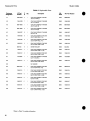
Model 11848A
Replaceable Parts
Table 6-3. Replaceable Parts
Reference
Designation
HP Part
Number
c Qty.
Description
D
Mfr.
Code
Mfr. Part Number
MB272
A4R273
MR274
A4R275
A4R276
0757-0442
0688-3157
0698-3167
0767-0438
0767-0438
RESISTOR 10K 1W -125W F T C - 0 + - 1 0 0
RESISTOR 19.6K 14» .126W F T C - 0 + - 1 0 0
RESISTOR 19.6K 1 % .125W F T C - 0 + - 1 0 0
RESISTOR 6.11K 1 % .126W F T C - 0 + -100
RESISTOR5.11K 1<M> .125W F T C 0 + -100
24546
24546
24546
24546
24546
CT4-1/8-T0-1002-F
CT4-1/8-T0-1962-F
CT4-1/8-T0-1962-F
CT4-1/8-T0-6111-F
CT4-1/8-T0-6111-F
MR277
A4R278
A4R279
MR280
A4R281
0698-0083
21004554
0767-0442
0698-3167
0698-4643
RESISTOR 1.96K 1<M> .125W F T C - 0 + -100
RESISTOR-TRMR600 10% C TOP-ADJ 1-TRN
RESISTOR 10K 1<H> .125W F T C - 0 + - 1 0 0
RESISTOR 19.6K 1<M> .125W F T C - 0 + - 1 0 0
RESISTOR487K 1«t> .125W F T C - 0 + - 1 0 0
24548
28480
24546
24546
28480
CT4-1/8-TO-1981-F
2100-0554
CT4-1/8-T0-1002-F
CT4-1/8-T0-1962-F
0698-4543
A4R282
A4R283
A4R284
A4R285
A4R286
0767-0467
0698-3582
0698-4480
0698-3497
0698-4434
1
1
1
1
1
RESISTOR 121K1W..125W F T C . 0 + - 1 0 0
RESISTOR41^K1<».125WFTC-0 + -100
RESISTOR 16.8K19t.125W F T C . 0 + -100
RESISTOR 6.04K1<H>.125WFTC-0 + -100
R E S I S T O R 2 J 2 K 1 W . 1 2 5 W F T C - 0 + -100
24546
24546
24546
24546
24646
CT4-1/8-T0-1213F
CT4-1/8-T0-4122-F
CT4-1/8-T0-1582-F
CT4-1/8-T0-604R-F
CT4-1/8-T0-2321-F
A4R287
A4R288
A4R289
A4R290
A4R291
0698-3495
0698-3443
1810-0329
0757-0199
0698-3441
1
RESISTOR 866 1 % . 1 2 5 W F T C . O + -100
RESISTOR287 1 % .125W F T C - 0 + -100
NETWORK-RES 10-SIP 7.5K OHM X 9
RESISTOR 21.6K 1 % .125W F T C - 0 + -100
RESISTOR 215 1 % .126W F T C 0 + -100
24546
24546
91637
24546
24546
CT4-1/8-T0-866R-F
CT4-1/8-T0-287RF
CSC10A01-762G/MSP10A01
CT4-1/8-T0-2162-F
CT4-1/8-T0-215RF
MR292
A4R293
A4R294
A4R295
A4R296
0757-0199
0698-3167
0698-0083
0698-4475
0698-3155
RESISTOR 21.5K 1 % .125W F T C 0 + -100
RESISTOR 19.6K 1 % .125W F T C - 0 + -100
RESISTOR 1.96K 1<H> .125W F T C - 0 + -100
RESISTOR9.76K1<H>.125WFTC0 + -100
RESISTOR4.64K 1<>» .12SW F T C - 0 + -100
24548
24546
24546
24546
24546
CT4-1/8-T0-2152-F
CT4-1/8-T0-1962-F
CT4-1/8-TO-1961-F
CT4-1/8-T0-9761-F
CT4-1/8-T0-4641-F
A4R297
0698-3162
RESISTOR46.4K 1 % .125W F T C - 0 + -100
24546
CT4-1/8-T0-4642-F
A4TP1*
A4TP2
A4TP3
A4TP4
A4TP6
1251-1998
1251-0600
1251-0600
1251-0600
1251-0600
CONNECTOR-SGL CONT SKT .02HNBSC-SZ
CONNECTORSQL CONT PIN 1.14-MM-BSC-SZ SQ
CONNECTOR-SGL CONT PIN 1.14-MM-BSC-SZ SQ
CONNECTOR-SGL CONT PIN 1.14-MM-BSC-SZ SQ
CONNECTOR-SGL CONT PIN 1.14-MM-BSC-SZ SQ
28480
28480
28480
28480
28480
1251-1998
1251-0600
1251-0600
1251-0600
1251-0600
A4TP6
A4TP7
A4TP8
A4TP9
A4TP10
1251-0600
1251-0600
1251-0600
1251-0600
1251-0600
CONNECTOR-SQL
CONNECTOR-SQL
CONNECTORSQL
CONNECTOR-SGL
CONNECTOR-SGL
CONT PIN 1.14-MM-BSC-SZ SQ
CONT PIN 1.14-MM-BSC-SZ SQ
CONT PIN 1.14-MM-BSC-SZ SQ
CONT PIN 1.14-MM-BSC-SZ SQ
CONT PIN 1.14-MM-BSC-SZ SQ
28480
28480
28480
28480
28480
1251-0600
1251-0600
1251-0600
1251-0600
1251-0600
A4TP11
A4TP12
A4TP13
A4TP14
A4TP15
1251-0600
1251-0600
1251-0600
1251-0600
1251-0600
CONNECTOR-SGL
CONNECTOPrSGL
CONNECTOR-SGL
CONNECTOR-SGL
CONNECTOR-SGL
CONT
CONT
CONT
CONT
CONT
1.14-MM-BSC-SZ SQ
1.14-MM-BSC-SZ SQ
1.14-MM-BSC-SZ SQ
1.14-MM-BSC-SZ SQ
1.14-MM-BSC-SZ SQ
28480
28480
28480
28480
28480
1251-0600
1251-0600
1251-0600
1251-0600
1261-0600
MTP16
A4TP17
A4TP18 A
A4TP19-200
A4TP201
1251-0600
1251-0600
1251-1998
CONNECTOR-SQL
CONNECTOR-SGL
CONNECTOR-SGL
NOT ASSIGNED
CONNECTOR-SGL
CONT PIN 1.14-MM-BSCSZ SQ
CONT PIN 1.14-MM-BSC-SZ SQ
CONT SKT .021-IN-BSC-SZ
28480
28480
28480
1251-0600
1251-0600
1251-1998
CONT PIN 1.14-MM-BSC-SZ SQ
28480
1251-0600
1251-0600
fRefer to Section 7 for u p d a t e i n f o r m a t i o n .
rev.0lAUG92
1
1
PIN
PIN
PIN
PIN
PIN
" F a c t o r y Selected C o m p o n e n t (Refer to S e c t i o n 5 ) .
A Errata part change.
49
Replaceable Parts
Model 11848A
Table 5. Replaceable Parts
C
0
A4TP202
A4TP203
A4TP204
A4TP205
A4TP206
1251-0600
1251-0600
1251-0600
1251-0600
1251-0600
0
0
0
0
0
CONNECTOR-SOL
CONNECTOR-SQL
CONNECTOR-SQL
CONNECTOR-SQL
CONNECTOR-SQL
1.14-MM-BSC-SZ
1.14-MM-BSC-SZ
1.14-MM-BSC-SZ
1.14-MM-BSC-SZ
1.14-MM-BSC-SZ
SO
SO
SO
SO
SO
28480
28480
28480
28480
28480
A4TP207
A4TP208
A4TP209
A4TP210
A4TP211
1251-0600
1251-0600
1251-0600
1251-0600
1251-0600
0
0
0
0
0
CONNECTOR-SQL CONT PIN 1.14-MM-BSC-SZ
CONNECTOR-SQL CONT PIN 1.14-MM-BSC-SZ
CONNECTOR-SQL CONT PIN 1.14-MM-BSC-SZ
CONNECTOR-SQL CONT PIN 1.14-MM-BSC-SZ
CONNECTOR-SQL CONT PIN 1.14-MM-BSC-SZ
SO
SO
SO
SO
SO
28460
28480
28480
28480
28480
inn
Q^
Mfr.
Code
HP Part
Number
m
Reference
Designation
A4TP212
A4TP213
A4TP214
A4TP215
A4TP216
1251-0600
1251-0600
1251-0600
1251-0600
1251-0600
0
0
0
0
0
CONNECTOR-SQL
CONNECTOR-SQL
CONNECTOR-SQL
CONNECTOR-SQL
CONNECTOR-SQL
SO
SO
SO
SO
SO
28480
28480
28480
28480
28480
12514600
12514600
12514600
12514600
12514600
A4TP217-219
A4TP220
1251-0600
0
NOT ASSIGNED
CONNECTOR-SQL CONT PIN 1.14-MM-BSC-SZ SO
28480
12514600
A4U1
A4U2
A4U3
A4U4
A4U5
0960-0640
0
1
28460
09804640
18264412
1826-0783
1826-0783
1
9
9
3
U-WAVE MIXER 1.6 QHZ MAX
NOT ASSIGNED
IC COMPARATOR PRCN DUAL 8-CHP-P PKG
IC OP AMP LOW-NOISE 8-OIP-C PKQ
IC OP AMP LOW-NOISE 8-OIP-C PKQ
27014
52063
62063
LM393N
XR5534ACN
XR5534ACN
A4U6
A4U7
A4U8
A4U9
A4U10-200
1820-1201
18584047
1858-0047
6081-2040
8
5
6
9
IC GATE TTL LS AND QUAD 2-INP
TRANSISTOR ARRAY 16-PIN PLSTC DIP
TRANSISTOR ARRAY 16-PIN PLSTC DIP
BURNIN1826-0035
NOT ASSIGNED
01295
13606
13606
28480
SN74LS0BN
ULN-2003A
ULN-2003A
6081-2040
A4U201
A4U202
A4U203
A4U204
A4U205
1826-0188
1820-1547
1820-1547
1820-1547
18264606
8
3
3
3
5
O/A 6-BIT 16-CERDIP BPLR
IC MULTIPLXR 8-CHAN-ANLQ16-OIP-C PKQ
K MULTIPLXR 8-CHAN-ANLQ 16-OIP-C PKQ
IC MULTIPLXR 8-CHAN-ANLQ 16-OIP-C PKQ
IC SWITCH ANLQ QUAD 16-DIP-C PKQ
04713
04713
04713
04713
17856
MC1408L-8
MC14051BCL
MC14051BCL
MC14051BCL
DQ201BK
A4U206
A4U207
A4U208
A4U209
A4U210
18264606
18264606
1820-1199
1820-1189
1820-1199
5
5
1
1
.1
IC SWITCH ANLQ QUAD 16-OIP-C PKQ
IC SWITCH ANLQ QUAD 16-DIP-C PKQ
IC INV TTL LS HEX 1-INP
IC INV TTL LS HEX 1-INP
IC INV TTL LS HEX 1-INP
17856
17856
01295
01295
01295
A4U211
A4U212
A4U213
A4U214
A4U215
1820-1112
16264785
18264783
16264783
18264753
8
1
9
9
3
IC FF TTL LS D-TYPE POS-EDQE-TRIQ
IC OP AMP LOW-BIAS-H-IMPD DUAL 8-DIP-C
IC OP AMP LOW-NOISE 8-DIP-C PKQ
IC OP AMP LOW-NOISE 8-DIP-C PKQ
IC OP AMP LOW-BIAS-H-IMPD QUAD 14-OIP-C
01295
01295
52063
52063
04713
SN74LS74AN
TL072ACJQ
XR5534ACN
XR5534ACN
MC34004BL
A4U216
A4U217
A4U218
A4U219
18264759
18264606
18264753
18264716
9
5
3
8
1
IC COMPARATOR QP QUAD 14-OIP-C PKQ
IC SWITCH ANLQ QUAD 16-DIP-C PKQ
IC OP AMP LOW-BIAS-H-IMPD QUAD 14-OIP-C
IC OP AMP LOW-NOISE DUAL 8-DIP-C PKQ
04713
17856
04713
16324
LM339J
DQ201BK
MC34004BL
NE5532AFE
A4VR1
A4VR2
19024952
19024952
6
6
2
WODE-ZNR 6.6V 5% DC-35 PD».4W TC—1--046%
OIODE-ZNR 5.6V 5% DO-35 PD».4W TC—f .046%
28480
28480
19024952
19024952
A4W1
35601-61622
2
1
3
2
SR 2.18 NO CONN
t Refer to Table 7 for update information.
50
CONT
CONT
CONT
CONT
CONT
CONT
CONT
CONT
CONT
CONT
PIN
PIN
PIN
PIN
PIN
PIN
PIN
PIN
PIN
PIN
1.14-MM-BSC-SZ
1.14-MM-BSC-SZ
1.14-MM-BSC-SZ
1.14-MM-BSC-SZ
1.14-MM-BSC-SZ
Mfr. Part h
ill
1
Description
3560141622
Replaceable Parts
Model 11848A
Table 6*3. Replaceable Parts
c
HP Part
Number
D
MP34A
11848-00020
7
1
MP35
0516-0682
7
2
UP36
21800584
0
2
MP37
0380-1739
0
2
MP38
0515-1246
1
19
MP39
1251-1249
3
1
MP40
0515-1246
1
MP41
1400-0249
MP42
1400-0062
MP43
MP44
Reference
Designation
MP45
Otv
uiy
11648-00020
O R D E R BY DESCRIPTION
28480
2190-0584
28480
0380-1739
SCREW-MACH M3 X 0.S 6MM-LQ PAN-HD
(ATTACH MIXER BRACKET TO DECK: OPTION 201 ONLY)
28480
0515-1246
ADAPTEftCOAX RTnANGLE F-SMA M-SMA
(OPTION 201 ONLY)
28480
0515-1246
19
SCREW-MACH M3 X 0.5 6MM4.G PAN-HD
(ATTACH A4 ASSEMBLY TO DECK)
28480
0515-1246
0
28
1400-0249
2
28480
1400-0062
1400-0611
0
6
CABLE TIE .062-.625-DIA .091-WD NYL
CLAMP-CABLE .375-DIA .38-WD SPR-STL
CLAMP-FL-CA 1-WD
28480
5
28480
14000611
11848-00004
7
2
1184800004
6
10
28480
0890340024
2
1
28480
12000819
0890300024
0515-1246
1
19
28480
0515-1246
0515-1402
1
30
REGULATOR BRACKET
SOCKET-XSTR 2-CONT TO3 SLDR-EYE
STRIP CUSHION S
SCREW-MACH M3 X 0.5 6MM-LG PAN-HD
(ATTACH REGULATOR BRACKET TO SIDE RAIL)
SCREW-MACH M3.5 X 0.6 8MM-LG PAN-HD
(ATTACH REGULATOR BRACKET TO MAIN DECK)
NOT ASSIGNED
CONNECTOR 2-PIN M UTILITY
CONTACT-CONN U/W-UTIL MALE CRP
CONNECTOR 2-PIN F UTILITY
CONTACT-CONN U/W-UTIL FEM CRP
FASTENER-SNAP IN PLUNGER
FASTENER-SNAP IN GROMMET
28480
1200-0819
6
1
1251-2097
3
2
1251-5037
7
2
1251-2418
2
2
1390-0365
8
2
1390-0366
9
2
MPS1
11848-00014
7
1
MPS2
0890-0025
6
1
MP53
0515-1362
6
6
R1
0757-0408
7
4
R2
0698-3152
8
4
R3
0757-0408
7
R4
0698-3152
8-
S1
3101-2216
3
T1
9100-4210
5
0362-0265
7
1400-0611
0
6
3050-2007
1
4
1826-1181
3
1
1826-0169
5
1
0340-0580
3
1820-0430
1
MP49
MPSO
U1
A
U2
U3
U4
U5
U6
VR1
VR2
VR3
1
3
.
1
1826-0523
5
1
0340-0580
3
3
18260423
4
1
0340-0580
3
3
0955-0162
0
1
1902-1369
1
2
0360-1700
3
2
1902-1369
1
0360-0040
2
2
4
0360-1089
1
2
1902-1217
8
1
0360-0016
2
4
fRefer to Section 7 for update information.
reu.0lAUG92
Mfr. Part Number
00000
1251-5036
MP48
MIXER BRACKET (OPTION 201 ONLY)
SCREW-MACH M3 X 0.5 18MM-LG PAN-HO
(ATTACH MIXER (U6) TO BRACKET: OPTION 201 ONLY)
WASHER-LK HLCL 3.0 MM 3.1-MM-IC
(OPTION 201 ONLY)
STANDOFF-HEX 11-MM-LQ M3.0 X 0.5 THD
(UNDER MIXER BRACKET: OPTION 201 ONLY)
Mfr.
Code
28480
MP46
MP47
Description
ORDER BY DESCRIPTION
28480
1251-5036
28480
1251-2097
28480
1251-5037
28480
1251-2418
28480
13900365
28480
13900366
REFERENCE BRACE ONCLUDES ATTACHING HARDWARE)
SPIRAL WRAP .188-2-OIA POLYETH (FOR CABLE HARNESS)
SCREW-MACH M3.5 X 0.6 6MM-LG
28480
28480
1184800014
1184800014
28480
0515-1382
RESISTOR 243 1 % .125W F T C - 0 + -100
RESISTOR 3.48K 1<H> .125W F T C - 0 + -100
RESISTOR 243 1 % .125W F T C - 0 + -100
RESISTOR 3.48K 1 % .125W F T C - 0 + -100
SWITCH-PD DPDT ALTNG 4A 250VAC
24546
CT4-1/8-T0-243R-F
24546
CT4-1/8-T0-3481-F
24546
CT4-1/8-T0-243R-F
24546
CT4-1/8-T0-3481-F
28480
3101-2216
TRANSFORMER-POWER 100/120/220/240V
CONNECTOR SGL CONT SKT 1.14-MM-BSC-SZ
CLAMP-FL-CA 1-WD
WASHERSHLDR NO. 6 .169-IN-1D .375-INJDD
28480
9100-4210
28480
03620265
IC340AKM1 P15V
IC V RGLTR TO-3
INSULATOR-XSTR THRM-CNDCT
IC 309 V RGLTR TOO
IC 337 V RGLTR T 0 3
INSULATOR-XSTR THRM-CNDCT
28480
1826-1181
27014
LM320K-15
28480
07263
0340-0580
LM309K
IC V RGLTR T 0 3
INSULATOR-XSTR THRWCNDCT
U-WAVE MIXER 26 GHZ MAX
27014
LM317K
28480
0340-0580
28480
09550162
DIODE-ZNR 1N3316B 17V 5% P D - 5 0 W I R - 6 U A
TERMINAL-SLDR LUG LK-MTG FOR#10-SCR
DIODE-ZNR 1N3316B 17V 5% P D - 5 0 W IR-5UA
TERMINAL-SLDR LUG LK-MTG FOFUH1/4-SCR
TERMINAL-SLDR LUG PL-MTG FOFW1/2-SCR
DIODE-ZNR 6.2V 5% D 0 4 PD - 10W TC - + .035%
TERMINAL-SLDR LUG LK-MTG FCfl-*4-SCR
28480
14000611
06540
2711-21562-PHF169-30
27014
LM337K
28480
03400580
28480
1902-1369
28480
0360-1700
26480
1902-1369
28480
03600040
28480
0360-1089
28480
1902-1217
28480
03600016
"Factory Selected Component (Refer to Section 5).
A Errata part change.
67
Replaceable Parts
Model 1184 8 A
Table 5. Replaceable Parts
Reference
Designation
HP Part
Number
C
D
W1
UBooO 00050
2
COAX CABLE ASSEMBLY F S.B-SMB
A3J16 TO A4J204 (3)
28480
0866040056
W2
1184841006
7
COAX CABLE ASSEMBLY F SMB-SMB
A3J1 TO A4J205 (1)
26460
1164841006
W3
•6601-60036
1
COAX CABLE ASSEMBLY F SMB-SMB
A3J2 TO A4J201 (6)
26480
•660140036
W4
•8601-60069
0
COAX CABLE ASSEMBLY F SMB-SMB
A3J3TOA4J10(89)
26460
8660140069
ws
1184641007
8
COAX CABLE ASSEMBLY F SMB-SMB
A3J4 TO C1 (4)
88480
1184841007
W6
11848-61008
8
COAX CABLE ASSEMBLY F BNC-SMB
A3J5 TO REAR PANEL J17 (5)
28480
1184641008
W7
1184641009
0
COAX CABLE ASSEMBLY F BNC-SMB
A3J8 TO REAR PANEL J14 (7)
28480
1184641009
W8
11846-61010
3
COAX CABLE ASSEMBLY F BNC-SMB
A3J7 TO FRONT PANEL J1 (80)
26480
1164841010
6040-7624
9
WASHER SHOULDER
28480
6040-7624
11648-61011
4
COAX CABLE ASSEMBLY F BNC-SMB
A3J8 TO FRONT PANEL J11 (87)
26480
1184641011
11648-61012
S
COAX CABLE ASSEMBLY F BNC-SMB
A6J2 TO FRONT PANEL J7 (85)
28480
1184841012
11672-60004
1
COAX CABLE ASSEMBLY F SMB-SMB
A3J10 TO A4J206 (2)
28460
1167240004
1164841013
6
COAX CABLE ASSEMBLY F BNC-SMB
A8J2 TO FRONT PANEL J8 (86)
26460
1164641013
W9
W10
W11
W12
Oty.
Description
*"''•
Code
Mfr. Part Number
NOT ASSIGNED
W13
W14
0895440105
7
COAX CABLE ASSEMBLY F BNC-SMB
A6J3 TO REAR PANEL J15 (6)
26480
0895440105
W15
1184841014
7
COAX CABLE ASSEMBLY F BNC-SMB
A7J2 TO FRONT PANEL J9 (81)
26480
1164S41014
W16
1184641015
8
COAX CABLE ASSEMBLY F BNC-SMB
ABJ2 TO FRONT PANEL J10 (83)
26460
1184841015
W17
1184841016
9
COAX CABLE ASSEMBLY F SMB-SMB
A3J9 TO A7J3 (82)
28480
1164641016
W18
1184841017
0
COAX CABLE ASSEMBLY F BNC-SMB
A4J9 TO REAR PANEL J18 (84)
28480
1164841017
W19
1184641018
1
COAX CABLE ASSEMBLY F BNC-SMB
A4J2 TO FRONT PANEL J1S (96)
28480
1184841018
W20
1164641019
2
COAX CABLE ASSEMBLY F BNC-SMB
A4J16 TO FRONT PANEL J12 (97)
28480
1184641019
fRefer to Table 7 for update information.
68
Service
Model 11848A
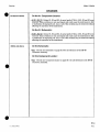
CHANGES
2749A and Above
On the A3 Component Locator:
• A3R208 - Change the reference designator of R208 to VRl.
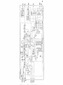
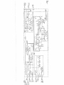
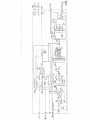
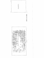
On the A3 Schematic:
• A3R207, R208, R209 - Change the value of R207 to 1.33k. Change the value of
R209 to 2.61k. Change the reference designator of R208 to VRl; connect the anode
to ground. Connect the cathode to the line connecting R207 and pin 15 of U208.
3138Aand Above
On the A3 Schematic:
• Change the board number to 11848-60203.
A3a
rev.01AUG92
96.1
Model 11848A
Service
Reserved for future
changes.
reu.01AUG92
Model 11848A
All serial prefixes
Service
On the A3 schematic:
R36 - Change the value of R36 to 261K ohms.
R41.R42, R51.R52 - Under 1 kHz LOW-PASS FILTER change R41 26.1K
to R51 2.61K and change R42 4.22K to R52 422K.
R41.R42, R56, R57 - Under 10 kHz LOW-PASS FILTER change R41 26.1K
to R56 2.61K and change R42 4.22K to R57 422K.
C34, R61 - Under AC/DC ADAPTIVE COUPLER locate U15 pin 13 and add
R61 251K in series with the +5V supply. Add C34 15 uF between U15 pin
13andR61.
R76, R82 - Under 10 Hz HIGH-PASS FILTER connect R76 to R79. Under
100 Hz HIGH-PASS FILTER connect R82 to R85.
3138Aand Above
On the A3 Schematic:
• Change the board number to 11848-60203.
rev.01AUG92
Service
Model 11848A
Reserved for future
changes.
A3b
98.2
rev.0lAUG92
Model 11848A
Service
CHANGES
2717A and Above
On the A3 Schematic:
• A3R110, R113 - Change the value of RllO to 2.5k. Change the value of R113 to
2.61k.
3138Aand Above
On the A3 Schematic:
• Change the board number to 11848-60203.
A3c
rev.0lAUG92
100.1
Model 11848A
Service
Reserved for future
changes
A3c
100.2
reu.0lAUG92
Model 11848 A
Service
CHANGES
All serial prefixes
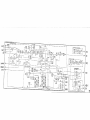
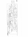
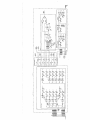
On the A4 schematic:
C14 - In OVERLOAD DETECTOR, change the value of C14 to 18pF.
2830A and above
On the schematic:
• L15 - In the upper right hand corner of the A4b schematic change the value
ofL15tol00UH.
• R35 - In the upper right hand corner of the A4b schematic change the value
ofR35to2.15Kohm.
Errata
On the A4 Schematic:
• C230 - Under PROGRAMMABLE AMPLIFIERS, near TP201, change the
value of C230 to 6800pF.
• R201 - Under PROGRAMMABLE AMPLIFIERS, near TP201, change the
valueofR201to287Q.
A4b
rev.01AUG92
104.1
Service
Model 11848 A
Reserved for future
changes.
A4b
104.2
rev.01AUG92
HP 11848A
PHASE NOISE INTERFACE
(Including Option 301)
Service Manual
SERIAL NUMBERS
This manual applies directly to instruments with
serial numbers prefixed:
2621A and all MAJOR changes that apply to your instrument
rev.lOJAN91
For additional important information about serial
numbers, refer to "INSTRUMENTS COVERED BY
THIS MANUAL" in Section 1.
Third Edition
"This material may be reproduced by or for the
U.S. Government pursuant to the Copyright License
under the clause at DFARS 52.227-7013 (APR 1988)"
Copyright ©HEWLETT-PACKARD COMPANY 1987
EAST 24001 MISSION AVENUE, TAF C-34, SPOKANE, WASHINGTON, U.S.A. 99220
Service Manual HP Part 11848-90004
Microfiche Service Manual HP Part 11848-90011
Printed in U.S.A. : MAY 1990
HEWLETT
EM PACKARD
fnm
Model 11848A Option 301
General Information
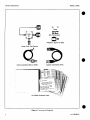
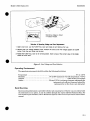
ACCESSORIES SUPPLIED
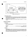
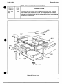
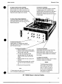
The accessories supplied are pieces of equipment that are shipped with every Interface. The
accessories are shown in Figure 1.
Line Power Cable. The line power cable may be supplied in several plug configurations, depending
on the destination of the original shipment. Refer to Power Cables in the Installation section of this
Service manual.
Fuses. Fuses with a 0.75A rating for 115 Vac (HP part number 2110-0063) and a 0.5A rating for 230
Vac (HP part number 2110-0012) are supplied. One fuse is factory installed according to the voltage
available in the country of original destination. Refer to Power Requirements in the Installation of
this Service manual.
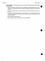
HP 3048A Option 301 Software and Manual Set. The HP 3048A software and associated manuals
are shipped with the Interface.
HP 3048A Software (HP part number 03048-10015).
HP 11848A Service Manual (HP part number 11848-90004).
HP 3048A Option 301 Installation Guide (HP part number 03048-90043).
HP 3048A Option 301 Operating Manual (HP part number 03048-90042).
HP 3048A Option 301 System Calibration Manual (HP part number 03048-90041).
HP 3048A Option 301 Reference Manual (HP part number 03048-90040).
50Q Termination. This 50O load is used to terminate the Interface's Spectrum Analyzer output if
no RF spectrum analyzer is available (HP part number 1250-0207).
Adapters, Type-N to BNC. Three adapters are provided for system operation (HP part number
1250-0780).
Cable Assemblies: BNC. Two 30 cm (12 in.) cables are provided for system operation (HP part
number 8120-1838).
Noise Floor Test Fixture. This test fixture is used to run performance tests (HP part number
11848-61032).
Cable Assembly: BNC to SMB. This cable assembly can be used during troubleshooting (HP part
number 08954-60105).
rev.WJANQl
General Information
Model 11848A Option 301
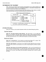
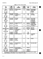
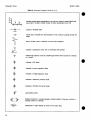
RECOMMENDED TEST EQUIPMENT
Table 1 lists the test equipment and accessories recommended for use in testing, adjusting, and
servicing the Interface. If any of the recommended equipment is unavailable, instruments with
equivalent minimum specifications may be substituted.
Tests for the Interface are performed during the HP 3048A Performance Tests which are available
in the HP 3048A Option 301 System Calibration Manual in Performance Tests.
Table 1. Recommended Test Equipment
Instrument Type
Dynamic Signal Analyzer
Counter (550 MHz)
Function Generator
Oscilloscope
Power Meter and Sensor
Model Number
HP 3561A
HP 5383A, HP 5386A
HP 3312A, HP 3325A
HP 1740 A
HP435BorHP436Awith
HP8481AorHP8482A
Use*
A.C.P.T**
P
P.T
T
T
* A = Adjustments, C = Functional Checks, P = Performance Tests, T = Troubleshooting
"" The HP 3561A is included with the HP 3048A system.
OPTIONS AVAILABLE
Options are variations on the standard instrument which can be ordered during the purchase.
Electrical Options
Option 201: Add High Frequency Phase Detector. This option adds a 1.2 to 18 GHz phase
detector to the Interface. This phase detector extends the range of carrier frequencies that can
be demodulated within the Interface without external down conversion by the System. All of the
HP 3048A specifications from 1.6 to 18 GHz carrier frequency are valid with this option.
Mechanical Options
Option 907: Front-Handle Kit. Front handles are provided when Option 907 is ordered. After
shipment, you can order a Front-Handle Kit as HP part number 5061-9689.
Option 908: Rack-Flange Kit. Rack flanges are provided for the HP 11848A Phase Noise Interface
when Option 908 is ordered. After shipment, you can order a Rack-Flange Kit as HP part number
5061-9677.
Option 909: Rack-Flange and Front-Handle Combination Kit. This is not a Front-Handle Kit and
a Rack-Flange Kit packaged together; it is a unique part that combines both functions. Combination
kits are provided for the HP 11848A Phase Noise Interface when Option 909 is ordered. After
shipment, you can order a Rack-Flange and Front-Handle Combination Kit as HP part number
5061-9683.
22.6
Replaceable Parts
Model 11848 A
Table 5. Replaceable Parts
Reference
Designation
A3J1-11
HP Part
Number
D
c
Qty
1260-1255
1
14
A3J12A
Description
CONNECTOR-RF SMB M PC 50 OHM
Mfr.
Code
Mfr. Part Num
28480
1250-1255
1250-1255
NOT ASSIGNED
A3J13
1250-1255
1
14
CONNECTOR-RF SMB M PC 50 OHM
28480
A3JH
1250-1255
1
14
CONNECTOR-RF SMB M PC 50 OHM
28480
1250-1255
1205-0095
0
1
HEAT SINK SGL TO-5/TO-39-CS
30161
1205-0095
A3J16
1251-4670
2
CONNECTOR 3-PIN M POST TYPE
28480
1251-4670
A3J201
1251-7264
6
CONN-POST TYPE .100-PIN-SPCG 34-CONT
28480
1251-7264
A3J15
NOT ASSIGNED
A3J202
NOT ASSIGNED
A3J203
1251-3825
7
CONNECTOR 5-PIN M POST TYPE
28480
1251-3825
A3J204
1251-8472
0
1
CONN-POST TYPE .100-PIN-SPCG 26-CONT
28480
1251-8472
A3L1
9100-1661
4
2
INDUCTOR RF-CH-MLD 2.2MH 5%
28480
9100-1661
9100-3560
A3L2-200
NOT ASSIGNED
A3L201
9100-3560
6
INDUCTOR RF-CH-MLD 5.6UH 5%
28480
A3L202
9100-3560
6
INDUCTOR RF-CH-MLD 5.6UH 5%
28480
9100-3560
A3L203
9100-3560
6
INDUCTOR RF-CH-MLD 5.6UH 5%
28480
9100-3560
A3L204
9140-0210
INDUCTOR RF-CH-MLD 100UH 5%
28480
9140-0210
A3L205
9140-0210
INDUCTOR RF-CH-MLD 100UH 5%
28480
9140-0210
A3L206
9140-0210
INDUCTOR RF-CH-MLD 100UH 5<M>
28480
9140-0210
A3L207
9140-0210
INDUCTOR RF-CH-MLD 100UH 5%
28480
9140-0210
A3L208
9140-0210
INDUCTOR RF-CH-MLD 100UH 5%
28480
9140-0210
A3L209
9140-0210
A3L210
9140-0137
A3L211
25
INDUCTOR RF-CH-MLD 100UH 5%
28480
9140-0210
INDUCTOR RF-CH-MLD 1MH 5%
28480
9140-0137
9140-0210
INDUCTOR RF-CH-MLD 100UH 5%
28480
9140-0210
A3L212
9140-0210
INDUCTOR RF-CH-MLD 100UH 5%
28480
9140-0210
A3L213
9140-0210
INDUCTOR RF-CH-MLD 100UH 5%
28480
9140-0210
A3L214
9140-0210
INDUCTOR RF-CH-MLD 100UH 5%
28480
9140-0210
A3L215
9140-0210
INDUCTOR RF-CH-MLD 100UH 5%
28480
9140-0210
A3L216
9140-0210
INDUCTOR RF-CH-MLD 100UH 5%
28480
9140-0210
A3L217
9140-0210
INDUCTOR RF-CH-MLD 100UH 5%
28480
9140-0210
A3L218
9140-0210
INDUCTOR RF-CH-MLD 100UH 5%
28480
9140-0210
A3L219
9140-0210
INDUCTOR RF-CH-MLD 100UH 5%
28480
9140-0210
A3L220
9140-0137
INDUCTOR RF-CH-MLD 1 MH 5%
28480
9140-0137
5
A3MP1a
1251-1998
1
CONNECTOR-SGL CONT SKT .025-IN-BSC-S2
28480
1251-1998
A3MP2
1390-0457
9
FASTENER-SNAP-IN PLGR 0.076 IN - .165 IN
28480
1390-0457
A3MP3
1390-0458
0
FASTENER-SNAP-IN GROM 0.076 IN - .165 IN
28480
1390-0458
A302
1855-0410
0
TRANSISTOR J-FET N-CHAN D-MODE TO-18 SI
28480
1855-0410
A3Q3
1855-0410
0
TRANSISTOR J-FET N-CHAN D-MODE TO-18 SI
28480
1855-0410
A3Q4
1855-0410
0
TRANSISTOR J-FET N-CHAN D-MODE TO-18 SI
28480
1B55-0410
TRANSISTOR J-FET 2N4416A N-CHAN D-MODE
04713
2N4416A
RESISTOR 1K 1 % .125W FTC = 0 + -100
24546
CT4-1/8-T0-1001-F
8
NOT ASSIGNED
A3Q1
3
NOT ASSIGNED
A3Q5-200
A3Q201
1855-0276
6
1
A3R1
0757-0280
3
12
NOT ASSIGNED
A3R2
NOT ASSIGNED
A3R3
A3R4
0698-3157
3
RESISTOR 19.6K 1 % ,125WFTC = 0 + -100
24546
CT4-1/8-T0-1962-F
A3R5
0698-3157
3
RESISTOR 19.6K 1 % .125W F T C 0 + - 1 0 0
24546
CT4-1/8-T0-1962-F
A3R6
0698-3157
3
RESISTOR 19.6K 1 % .125W F T C 0 + -100
24546
CT4-1/8-T0-1962-F
A3R7
0698-3157
3
RESISTOR 19.6K 1 % .125W F TC = 0 + -100
24546'
CT4-1/8-T0-1962-F
A3R8
0698-3157
3
RESISTOR 19.6K 1 % .126W F TC =0 +-100
24546
CT4-1/8-T0-1962-F
A3R9
0698-3460
1
8
RESISTOR 422K 1 % . 125W F TC = 0 + -100
28480
0698-3460
A3R10
0698-3454
3
3
RESISTOR 215K 1 % .125W FTC = 0 + -100
24546
CT4-1/8-T0-2153-F
A3R15
0757-0444
1
4
RESISTOR 12.1K 1 % .125W FTC = 0 + -100
24546
CT4-1/8-TO-1212-F
A3R16
0698-3157
3
RESISTOR 19.6K 1 % .125W F TC = 0 +-100
24546
CT4-1/8-T0-1962-F
A3R17
0698-3157
3
RESISTOR 19.6K 1 % .125W F T C . 0 + -100
24546
CT4-1/8-T0-1962-F
A3R18
0698-3450
9
RESISTOR 42.2K 1 % .125W F T C = 0 + -100
24546
CT4-1/B-T0^I222-F
20
A3R11-14
NOT ASSIGNED
4
fRtrf'tM- to Table 7 for update i n f o r m fit inn.
rev.09OCT90
.A E r r a t a part change
33
Model 11848A
Replaceable Parts
Table 5. Replaceable Parts
Reference
Designation
HP Part
Number
c
Orv
u i y
3
29
9
8
4
12
D
A3R19
A3R20
A3R21
A3R22
A3R23
0757-0438
0698-0084
0698-8827
0757-0280
0698-3223
A3R24
A3R25
A3R26
A3R27
A3R28
0757-0420
0698^t421
0698-4421
0698-4421
0757-0422
3
4
6
11
A3R29
A3R30
A3R31
A3R32
A3R33
0757-0422
0757-0417
0757-0400
0698-0084
0698-0084
5
A3R34
A3R35
A3R36
A3R37
A3R38
0698-3460
0698-3460
0698-3455
0698-3450
0757-0438
A3R39
A3R40
A3R41
A3R42
A3R43
0757-0438
0698-3450
0698-3159
0698-3154
0757-0438
3
A3R44
A3R45
A3R46
A3R47
A3R48
0757-0438
0698-3154
0698-0085
0698-3447
0757-0438
3
A3R49
A3R50
A3R51
A3R52
A3R53
0757-0438
0698-3154
0698-0085
0698-3447
0757-0438
3
A3R54
A3R55
A3R56
A3R57
A3R58
0757-0438
0698-3154
0698-0085
0698-3447
0757-0438
3
A3R59
A3R60
A3R61
A3R62
A3R63
0757-0438
0698^1421
0698-3454
0698-0084
0698-8827
3
A3R64
A3R65
A3R66
A3R67
A3R68
0698-3460
0698-3154
0767-O438
0757-0438
2100-0558
3
4
3
6
6
5
2
Description
Mfr. Part Num
RESISTOR
RESISTOR
RESISTOR
RESISTOR
RESISTOR
5.11K 1 % .125W F T C - 0 + -100
2.15K 1 % .125W F T C 0 + -100
1M 1 % .125W F T C = 0 + -100
1K 1%.125W F T C = 0 + -100
1.24K 1 tf> . 125W F TC - 0 + -100
24546
24546
28480
24546
24546
CT4-1/8-T0-5111-F
CT4-1/8-T0-2151-F
0698-8827
CT4-1/8-T0-1001-F
CT4-1/8-T0-1241-F
RESISTOR
RESISTOR
RESISTOR
RESISTOR
RESISTOR
750
249
249
249
909
24546
24546
24546
24546
24546
CT4-1/8-T0-751-F
CT4-1/8-T0-249R-F
CT4-1/8-T0-249R-F
CT4-1/8-T0-249R-F
CT4-1/8-T0-809R-F
24546
24546
24546
24546
24546
CT4-1/8-T0-909R-F
CT4-1/8-T0-562R-F
CT4-1/8-T0-90R9-F
CT4-1/8-T0-2151-F
CT4-1/8-T0-2151-F
1 % .12SW F T C - 0 + -100
1 % .125W F TC = 0 + -100
1 % . 125W F TC = 0 + -100
1 % .125W F T C 0 + -100
1 % . 125W F TC = 0 + -100
8
1
9
1
RESISTOR 909 1 % . 125W F TC - 0 + -100
RESISTOR 562 1 % . 125W F TC - 0 + -100
RESISTOR 90.9 1 % .125W F TC = 0 + -100
RESISTOR 2.15K 1<K> .125W FTC = 0 + -100
RESISTOR 2.15K 1 % .125W F TC = 0 + -100
1
RESISTOR 422K 1 % . 125W F TC - 0 + -100
RESISTOR 422K 1 % . 125W F TC - 0 + -100
RESISTOR 261K 1 % .125W FTC = 0 + -100
RESISTOR 42.2K 1 % .125W F TC = 0 + -100
RESISTOR 5.11K 1 % .125W F T C = 0 + -100
28480
28480
24546
24546
24546
0698-3460
0698-3460
CT4-1/8-T0-2613-F
CT4-1/8-T0-4222-F
CT4-1/8-T0-5111-F
5
1
0
10
RESISTOR 5.11K
RESISTOR 42.2K
RESISTOR 26.1K
RESISTOR 4.22K
RESISTOR 5.1 IK
24546
24546
24546
24546
24546
CT4-1/8-T0-5111-F
CT4-1/8-T0^l222-F
CT4-1/8-T0-2612-F
CT4-1/8-T04221-F
CT4-1/8-T0-5111-F
RESISTOR 5.11K 1 % .125W F T C 0 + -100
RESISTOR 4.22K 1 % .125W FTC = 0 + -100
RESISTOR 2.61K 1 % .125W FTC = 0 + -100
RESISTOR 422 1 % .125W F TC = 0 + -100
RESISTOR 5.11K1W . 1 2 5 W F T C O + -100
24546
24546
24546
24546
24546
CT4-1/8-T0-5111-F
CT4-1/8-TCM221-F
CT4-1/8-T0-2611-F
CT4-1/8-T0-422R-F
CT4-1/8-T0-5111-F
RESISTOR 5.11K 1 % .125W FTC = 0+-100
RESISTOR 4.22K 1 % .125W F T C 0 + -10O
RESISTOR 2.61K 1 % .125W FTC = 0 + -100
RESISTOR 422 1 % .125W F TC = 0 + -100
RESISTOR 5.11K 1 % .125W F T C 0 + -100
24546
24546
24546
24546
24546
CT4-1/8-T0-5111-F
CT4-1/8-TO-4221-F
CT4-1/8-T0-2611-F
CT4-1/8-T0-422R-F
CT4-1/8-T0-5111-F
RESISTOR 5.UK 1 % .125W F T C - 0 + -100
RESISTOR 4.22K 1 % . 125W F TC = 0 + -100
RESISTOR 2.61K 1 % .125W FTC = 0 + -100
RESISTOR 422 1 % .125W FTC = 0 + -100
RESISTOR 5.11K 1 % .125W F T C 0 + -10O
24546
24546
24546
24546
24546
CT4-1/8-T0-5111F
CT4-1/8-TCM221-F
CT4-1/8-T0-2611-F
CT4-1/8-T0422R-F
CT4-1/8-T0-5111-F
RESISTOR
RESISTOR
RESISTOR
RESISTOR
RESISTOR
24546
24546
24546
24546
28480
CT4-1/8-T0-5111-F
CT4-1/8-T0-249R-F
CT4-1/8-T0-2153-F
CT4-1/8-T0-2151-F
0698-8827
28480
24546
24546
24546
28480
0698-3460
CT4-1/8-TO-4221-F
CT4-1/8-T0-5111-F
CT4-1/8-T0-5111-F
2100-0558
9
9
1
1
4
9
3
9
3
0
0
3
4
5
3
0
0
4
3
0
0
4
3
6
3
9
4
1
0
3
3
9
6
1 % .125W F T C O + -100
1 % . 125W F TC = 0 + -100
1 % .125W F T C - 0 + -100
1 % . 125W F TC = 0 + -100
1 % .125W F T C - 0 + -100
5.11K Wo .125W FTC = 0 + -100
249 1 % .125W F TC = 0 +-100
215K 1 % . 125W F TC = 0 + -100
2.15K 1 % .125W FTC = 0+-100
1M 1 % .125W FTC = 0 + -100
RESISTOR 422K 1 % . 125W F TC - 0 + -100
RESISTOR 4.22K Wo .125W F T C 0 + -100
RESISTOR 5.1 IK 1 % .125W FTC = 0 + -100
RESISTOR 5.11K 1 % .125W F T C . 0 + -100
RESISTOR-TRMR 20K 10% C TOP-ADJ 1-TRN
j Refer to Table 7 for update i n f o r m a t i o n .
34
Mir.
Code
A E r r a t a part change
Replaceable Parts
Model 11848A
Table 5. Replaceable Parts
Description
Mfr.
Code
CAPACITOR-FXD
CAPACITOR-FXD
CAPACITOR-FXD
CAPACITOR-FXD
CAPACITOR-FXD
22UF+-10% 35VDC TA
22UF+-10% 35VDC TA
1UF +-10% 200VDC POLYE
1UF +-10% 200VDC POLYE
.1UF +-10% 200VDC POLYE
56289
56289
28480
28480
28480
150D226X9035R2
150D226X9035R2
0160-0168
0160-0168
0160-0168
2
4
4
1
9
CAPACITOR-FXD
CAPACITOR-FXD
CAPACITOR-FXD
CAPACITOR-FXD
CAPACITOR-FXD
1000PF +-5% 100VDC CER
1UF +-10% 50VDC CER
1UF +-10% 50VDC CER
47PF +-5% 100VDC CER 0+-30
51PF +-5% 100VDC CER 0+-30
28480
28480
28480
28480
28480
0160-4822
0160-4535
0160-4535
0160-4805
0160-5348
0160-4787
0160-4801
0160-4801
0160-4787
0160-4535
8
7
7
8
4
CAPACITOR-FXD
CAPACITOR-FXD
CAPACITOR-FXD
CAPACITOR-FXD
CAPACITOR-FXD
22PF +-5% 100VDC CER 0+-30
100PF +-5% 100VDC CER
100PF +-5% 100VDC CER
22PF +-5% 100VDC CER 0+-30
1UF +-10% 50VDC CER
28480
28480
28480
28480
28480
0160-4787
0160-4801
0160-4801
0160-4787
0160-4535
A4C228
A4C229
A4C230
A4C231
0160-4535
0160-4535
0160-4831
0160-4535
4
4
3
4
CAPACITOR-FXD
CAPACITOR-FXD
CAPACITOR-FXD
CAPACITOR-FXD
1UF +-10% 50VDC CER
1UF +-10% 50VDC CER
4700PF +-10% 100VDC CER
1UF +-10% 50VDC CER
28480
28480
28480
28480
0160-4535
0160-4535
0160-4831
0160-4535
A4CR1
A4CR2
A4CR3
A4CR4
A4CR5
1901-1098
1901-1098
1901-1098
1901-1098
1901-1098
3
3
3
3
3
DIODE-SWITCHING
DIODE-SWITCHING
DIODE-SWITCHING
DIODE-SWITCHING
DIODE-SWITCHING
80V 200MA
80V 200MA
80V 200MA
80V 200MA
80V 200MA
2NS
2NS
2NS
2NS
2NS
DO-35
DO-35
DO-35
DO-35
DO-35
9N171
9N171
9N171
9N171
9N171
1N4150
1N4150
1N4150
1N4150
1N4150
A4CR6
A4CR7
A4CR8
A4CR9
A4CR10
1901-1098
1901-1098
1901-1098
1901-1098
1901-1098
3
3
3
3
3
DIODE-SWITCHING
DIODE-SWITCHING
DIODE-SWITCHING
DIODE-SWITCHING
DIODE-SWITCHING
80V 200MA
80V 200MA
80V 200MA
80V 200MA
80V 200MA
2NS
2NS
2NS
2NS
2NS
DO-35
DO-35
DO-35
DO-35
DO-35
9N171
9N171
9N171
9N171
9N171
1N4150
1N4150
1N4150
1N4150
1N4150
A4CR11
A4CR12
A4CR13
A4CR14
A4CR15
1901-1098
1901-1098
1901-1098
1901-1098
1901-1098
3
3
3
3
3
DIODE-SWITCHING
DIODE-SWITCHING
DIODE-SWITCHING
DIODE-SWITCHING
DIODE-SWITCHING
80V 200MA
80V 200MA
80V 200MA
80V 200MA
80V 200MA
2NS
2NS
2NS
2NS
2NS
DO-35
DO-35
DO-35
DO-35
DO-35
9N171
9N171
9N171
9N171
9N171
1N4150
1N4150
1N4150
1N4150
1N4150
A4CR16
A4CR17
A4CR18
A4CR19
A4CR20
1901-1098
1901-1098
1901-1098
1901-1098
1901-1098
3
3
3
3
3
DIODE-SWITCHING
DIODE-SWITCHING
DIODE-SWITCHING
DIODE-SWITCHING
DIODE-SWITCHING
80V 200MA
80V 200MA
80V 200MA
80V 200MA
80V 200MA
2NS
2NS
2NS
2NS
2NS
DO-35
DO-35
DO-35
DO-35
DO-35
9N171
9N171
9N171
9N171
9N171
1N4150
1N4150
1N4150
1N4150
1N4150
A4CR21
A4CR22
A4CR23
A4CR24
A4CR25
1901-1098
3
DIODE-SWITCHING 80V 200MA 2NS DO-35
9N171
1N4150
1901-1098
1901-1098
3
3
DIODE-SWITCHING 80V 200MA 2NS DO-35
DIODE-SWITCHING 80V 200MA 2NS DO-35
9N171
9N171
1N4150
1N4150
A4CR26
A4CR27
1901-1098
1901-1098
3
3
DIODE-SWITCHING 80V 200MA 2NS DO-35
DIODE-SWITCHING 80V 200MA 2NS DO-35
9N171
9N171
1N4150
1N4150
A4CR28
A4CR29
A4CR30-200
A4CR201
A4CR202
1901-1098
1901-1098
3
3
80V 200MA 2NS DO-35
80V 200MA 2NS DO-35
9N171
9N171
1N4150
1N4150
1901-1098
1901-1098
3
3
DIODE-SWITCHING
DIODE-SWITCHING
NOT ASSIGNED
DIODE-SWITCHING
DIODE-SWITCHING
80V 200MA 2NS DO-35
80V 200MA 2NS DO-35
9N171
9N171
1N4150
1N4150
HP Part
Number
c
A4C213
A4C214
A4C215
A4C216
A4C217
0180-1794
0180-1794
0160-0168
0160-0168
0160-0168
3
3
1
1
1
A4C218
A4C219
A4C220
A4C221
A4C222
0160-4822
0160-4535
0160-4535
0160-4805
0160-5348
A4C223
A4C224
A4C225
A4C226
A4C227
Reference
Designation
Qty.
D
Mfr. Part Nun
f Refer to Table 7 for update information.
rev.2lSEP89
41
Model 11848A
Replaceable Parts
Table 5. Replaceable Parts
Reference
Designation
HP Part
Number
c
Qty.
Mfr.
Code
Description
D
A4CR203
A4CR204
A4CR205
A4CR206
A4CR205
A4CR206
A4CR207
1901-1098
1901-1098
3
3
1902-0952
1902-0952
1901-1098
A4CR208
A4CR209
A4CR210
A4CR211
A4CR212
Mfr. Pai
9N171
9N171
1N4150
1N4150
6
6
3
DIODE-SWITCHING 80V 200MA 2NS DO-35
DIODE-SWITCHING 80V 200MA 2NS DO-35
NOT ASSIGNED
NOT ASSIGNED
DIODE-ZNR 5.6V 5% DO-35 PD=.4W TC=+.046%
DIODE-ZNR 5.6V 5% DO-35 PD=.4W TC=+.046%
DIODE-SWITCHING 80V 200MA 2NS DO-35
28480
28480
9N171
1902-0952
1902-0952
1N4150
1901-1098
1901-1098
1901-1098
1901-1098
1901-1098
3
3
3
3
3
DIODE-SWITCHING 80V
DIODE-SWITCHING 80V
DIODE-SWITCHING 80V
DIODE-SWITCHING 80V
DIODE-SWITCHING 80V
200MA 2NS DO-35
200MA 2NS DO-35
200MA 2NS DO-35
200MA 2NS DO-35
200MA 2NS DO-35
9N171
9N171
9N171
9N171
9N171
1N4150
1N4150
1N4150
1N4150
1N4150
A4CR213
A4CR214
A4CR215
A4CR216
A4CR217
1901-1098
1901-1098
1901-1098
1901-1098
1901-1098
3
3
3
3
3
DIODE-SWITCHING 80V
DIODE-SWITCHING 80V
DIODE-SWITCHING 80V
DIODE-SWITCHING 80V
DIODE-SWITCHING 80V
200MA 2NS DO-35
200MA 2NS DO-35
200MA 2NS DO-35
200MA 2NS DO-35
200MA 2NS DO-35
9N171
9N171
9N171
9N171
9N171
1N4150
1N4150
1N4150
1N4150
1N4150
A4CR218
1901-1098
3
DIODE-SWITCHING 80V 200MA 2NS DO-35
A4E1
A4E2
A4E3
A4E4
A4E5
9170-0894
9170-0894
9170-0894
9170-0894
9170-0894
0
0
0
0
0
CORE-SHIELDING BEAD
CORE-SHIELDING BEAD
CORE-SHIELDING BEAD
CORE-SHIELDING BEAD
CORE-SHIELDING BEAD
28480
28480
28480
28480
28480
9170-0894
9170-0894
9170-0894
9170-0894
9170-0894
A4E6
A4E7
A4E8
A4E9
A4E10
9170-0894
9170-0894
9170-0894
9170-0894
9170-0894
0
0
0
0
0
CORE-SHIELDING BEAD
CORE-SHIELDING BEAD
CORE-SHIELDING BEAD
CORE-SHIELDING BEAD
CORE-SHIELDING BEAD
28480
28480
28480
28480
28480
9170-0894
9170-0894
9170-0894
9170-0894
9170-0894
A4E11
A4E12
A4E13
A4E14
A4E15
9170-0894
9170-0894
9170-0894
9170-0894
9170-0894
0
0
0
0
0
CORE-SHIELDING BEAD
CORE-SHIELDING BEAD
CORE-SHIELDING BEAD
CORE-SHIELDING BEAD
CORE-SHIELDING BEAD
28480
28480
28480
28480
28480
9170-0894
9170-0894
9170-0894
9170-0894
9170-0894
A4E16
A4E17
A4E18
A4E19
A4E20
9170-0894
9170-0894
9170-0894
9170-0894
9170-0894
0
0
0
0
0
CORE-SHIELDING BEAD
CORE-SHIELDING BEAD
CORE-SHIELDING BEAD
CORE-SHIELDING BEAD
CORE-SHIELDING BEAD
28480
28480
28480
28480
28480
9170-0894
9170-0894
9170-0894
9170-0894
9170-0894
A4E21
A4E22
A4E23
A4E24
A4E25
9170-0894
9170-0894
9170-0894
9170-0894
9170-0894
0
0
0
0
0
CORE-SHIELDING BEAD
CORE-SHIELDING BEAD
CORE-SHIELDING BEAD
CORE-SHIELDING BEAD
CORE-SHIELDING BEAD
28480
28480
28480
28480
28480
9170-0894
9170-0894
9170-0894
9170-0894
9170-0894
A4E26
A4E27
A4E28
9170-0894
9170-0894
9170-0894
0
0
0
CORE-SHIELDING BEAD
CORE-SHIELDING BEAD
CORE-SHIELDING BEAD
28480
28480
28480
9170-0894
9170-0894
9170-0894
A4F1
A4F2
A4F3
A4F4
A4F5
2110-0757
2110-0757
2110-0757
2110-0757
1
1
1
1
FUSE-SUBMINIATURE 0.63A
FUSE-SUBMINIATURE 0.63A
FUSE-SUBMINIATURE 0.63A
FUSE-SUBMINIATURE 0.63A
NOT ASSIGNED
75915
75915
75915
75915
251.062
251.062
251.062
251.062
A4F6
2110-0757
1
FUSE-SUBMINIATURE 0.63A 125V .28X.095 UL
125V
125V
125V
125V
.28X.095 UL
.28X095 UL
.28X.095 UL
.28X.095 UL
1N4150
251.062
f Refer to Table 7 for update information.
42
rev.21SEP89
Model 11848 A
Replaceable
Table 5. Replaceable Parts
Reference
Designation
HP Part
Number
Qty.
Description
Mfr.
Code
Mfr. Part
A4J1
A4J2
A4J3-J5 A
1250-1255
1250-1255
CONNECTOR-RF SMB M PC 50-OHM
CONNECTOR-RF SMB M PC 50-OHM
NOT ASSIGNED
28480
28480
1250-1255
1250-1255
A4J6
A4J7
A4J8
A4J9
A4J10
5021-2826
5021-2826
5021-2826
1250-1255
1250-1255
RFFTTNG
RFFTTNG
RFFTTNG
CONNECTOR-RF SMB M PC 50-OHM
CONNECTOR-RF SMB M PC 50-OHM
28480
28480
28480
28480
28480
5021-2826
5021-2826
5021-2826
1250-1255
1250-1255
CONNECTOR-RF SMA M PC 50-OHM
CONNECTOR 5-PIN M POST TYPE
NOT ASSIGNED
CONNECTOR-RF SMB M PC 50-OHM
28480
28480
1250-1707
1251-3825
28480
1250-1255
CONNECTOR-RF SMB M PC 50-OHM
NOT ASSIGNED
CONNECTOR-RF SMB M PC 50-OHM
CONN-POST TYPE .100-PIN-SPCG 50-CONT
CONN-POST TYPE .100-PIN-SPCG 10-CONT
28480
1250-1255
28480
28480
28480
1250-1255
1251-8929
1252-0243
A4J11A
A4J12
A4J13
A4J14
A4J15
NOT ASSIGNED
1250-1707
1251-3825
A4J16
A4J17-200
A4J201
A4J202
A4J203
1250-1255
A4J204
A4J205
A4J206
A4J207 A
12514670
1250-1255
1250-1255
CONNECTOR 3-PIN M POST TYPE
CONNECTOR-RF SMB M PC 50-OHM
CONNECTOR-RF SMB M PC 50-OHM
NOT ASSIGNED
28480
28480
28480
12514670
1250-1255
1250-1255
A4K1
A4K2
A4K3
A4K4
A4K5
0490-1318
0490-1318
0490-0916
0490-0916
0490-1515
RELAY 2C 12VDC-COIL .5A 28VDC
RELAY 2C 12VDC-COIL .5A 28VDC
RELAY-REED 1A 500MA 100VDC 5VDC-COIL
RELAY-REED 1A 500MA 100VDC 5VDC-COIL
RELAY-REED 1C 1A 150VDC 5VDC-COIL 3VA
28480
28480
28480
28480
71707
0490-1318
0490-1318
0490-0916
0490-0916
2911-05-300
A4K6
A4K7
A4K8
A4K9
A4K10
0490-0916
0490-0916
0490-1318
0490-1318
0490-0916
RELAY-REED 1A 500MA 100VDC 5VDC-COIL
RELAY-REED 1A 500MA 100VDC 5VDC-COIL
RELAY 2C 12VDC-COIL ,5A 28VOC
RELAY 2C 12VDC-COIL .5A 28VDC
RELAY-REED 1A 500MA 100VDC 5VDC-COIL
28480
28480
28480
28480
28480
0490-0916
0490-0916
0490-1318
0490-1318
0490-0916
A4K11
A4K12
A4K13
A4K14
0490-1318
0490-1318
0490-1515
0490-1318
RELAY 2C 12VDC-COIL ,5A 28VDC
RELAY 2C 12VDC-COIL .5A 28VDC
RELAY-REED 1C 1A 150VDC 5VDC-COIL3VA
RELAY 2C 12VDC-COIL .5A 28VDC
28480
28480
71707
28480
0490-1318
0490-1318
2911-05-300
0490-1318
A4L1
A4L2
A4L3
A4L4
A4L5
9100-3818
9140-0637
9100-3807
9140-0638
9140-0262
INDUCTOR
INDUCTOR
INDUCTOR
INDUCTOR
INDUCTOR
RF-CH-MLD
RF-CH-MLD
RF-CH-MLD
RF-CH-MLD
RF-CH-MLD
47NH 20%
68NH 20% .166DX.385LG
110NH 5%
510NH 5%
200NH 5%
28480
28480
28480
28480
28480
9100-3818
9140-0637
9100-3807
9140-0638
9140-0262
A4L6
A4L7
A4L8
A4L9
A4L10
9140-0262
9140-0261
9140-0399
9100-3913
9100-3912
INDUCTOR
INDUCTOR
INDUCTOR
INDUCTOR
INDUCTOR
RF-CH-MLD
RF-CH-MLD
RF-CH-MLD
RF-CH-MLD
RF-CH-MLD
200NH 5%
100NH 5%
2.2UH 5%
3.3UH 5%
15UH 5%
28480
28480
28480
28480
28480
9140-0262
9140-0261
9140-0399
9100-3913
9100-3912
A4L11
A4L12
A4L13
A4L14
9100-3561
9100-3561
9140-0285
INDUCTOR RF-CH-MLD 6.2UH 5%
INDUCTOR RF-CH-MLD 6.2UH 5%
INDUCTOR RF-CH-MLD 3UH 5%
NOT ASSIGNED
28480
28480
28480
9100-3561
9100-3561
9140-0285
9140-0137
INDUCTOR RF-CH-MLD 1MH 5%
28480
9140-0137
9140-0210
INDUCTOR RF-CH-MLD 100UH 5% .166DX.385LG
28480
9140-0210
1250-1255
1251^929
12524243
2621A to 28ISA
A4L1B
2830A AND AliOVK
A4L1S
i Refer to Table 7 for update i n f o r m a t i o i
rev.OOOCTOO
A
E r r a t a part change
Replaceable Parts
Model 11848A
Table 5. Replaceable Parts
Reference
Designation
HP Part
Number
c
D
9140-0636
9140-0131
9100-1661
9140-0210
A4L21
A4L22
A4L23
A4L24
A4L25
9100-3560
9140-0210
9140-0137
9140-0144
9140-0144
6
A4L26
A4L27
A4L28
A4L29
A4L30
9140-0144
9140-0137
9140-0144
9140-0144
9140-0144
0
A4L31
A4L32
A4L33
A4L34
A4L35
9140-0144
9140-0144
9140-0144
9140-0144
9140-0144
0
A4L36
A4L37
A4L38
A4L39
A4L40
9140-0144
9140-0144
9140-0144
9140-0144
9140-0144
0
A4L41
A4L42
A4L4M5
A4L46
9140-0144
9140-0144
0
9140-0144
0
A4L47
A4L48
9140-0144
9140-0138
0
2
1
A4MP1
A4MP2
A4MP3
A4MP4 A
A4MP5
0515-0655
0535-0004
0535-0034
1251-1998
1251-5595
4
2
A4MP6
A4MP7
A4MP8
2190-0584
3050-0891
35601-01209
0
2
7
2
9
1
5
1
5
1
4
1
1
1
23
0
1
0
0
0
0
0
0
0
0
0
0
0
0
9
5
Mfr. Part Number
NOT ASSIGNED
INDUCTOR 40MH 5% .55DX.45LQ
INDUCTOR RF-CH-MLD 10MH 5 1 *
INDUCTOR RF-CH-MLD 2.2MH 5%
INDUCTOR RF-CH-MLD 100UH 5%
28480
28480
28480
28480
9140-0636
9140-0131
9100-1661
9140-0210
INDUCTOR
INDUCTOR
INDUCTOR
INDUCTOR
INDUCTOR
RF-CH-MLD
RF-CH-MLD
RF-CH-MLD
RF-CH-MLD
RF-CH-MLD
5.6UH 5%
100UH 5%
1MH 5%
4.7UH 10%
4.7UH 10%
28480
28480
28480
28480
28480
9100-3560
9140-0210
9140-0137
9140-0144
9140-0144
INDUCTOR
INDUCTOR
INDUCTOR
INDUCTOR
INDUCTOR
RF-CH-MLD 4.7UH 10%
RF-CH-MLD 1MH 5%
RF-CH-MLD 4.7UH 10%
RF-CH-MLD 4.7UH 10%
RF-CH-MLD 4.7UH 10%
28480
28480
28480
28480
28480
9140-0144
9140-0137
9140-0144
9140-0144
9140-0144
INDUCTOR
INDUCTOR
INDUCTOR
INDUCTOR
INDUCTOR
RF-CH-MLD 4.7UH
RF-CH-MLD 4.7UH
RF-CH-MLD 4.7UH
RF-CH-MLD 4.7UH
RF-CH-MLD 4.7UH
10%
10%
10%
10%
10%
28480
28480
28480
28480
28480
9140-0144
9140-0144
9140-0144
9140-0144
9140-0144
INDUCTOR
INDUCTOR
INDUCTOR
INDUCTOR
INDUCTOR
RF-CH-MLD
RF-CH-MLD
RF-CH-MLD
RF-CH-MLD
RF-CH-MLD
10%
10%
10%
10%
10%
28480
28480
28480
28480
28480
9140-0144
9140-0144
9140-0144
9140-0144
9140-0144
INDUCTOR RF-CH-MLD 4.7UH 10%
INDUCTOR RF-CH-MLD 4.7UH 10%
NOT ASSIGNED
INDUCTOR RF-CH-MLD 4.7UH 10%
28480
28480
9140-0144
9140-0144
28480
9140-0144
INDUCTOR RF-CH-MLD 4.7UH 10%
INDUCTOR RF-CH-MLD 180UH 5%
28480
28480
9140-0144
9140-0138
SCREW-MACH M3 X 0.5 8MM-LG PAN-HD
NUT-HEX DBL-CHAM M3 X 0.5 2.4MM-THK
NUT-HEX DBL-CHAM M4 X 0.7 3.2MM-THK
CONNECTOR-SGL CONT SKT .021-IN-BSC-SZ
POLARIZING KEY-POST CONN
00000
00000
28480
28480
28480
ORDER BY DESCRIPTION
ORDER BY DESCRIPTION
0535-0034
1251-1998
1251-5595
WASHER-LK HLCL 3.0 MM 3.1-MM-ID
WASHER-FL MTLC 3.0 MM 3.3-MM-ID
BRACKET-MIXER-1
28480
28480
28480
2190-0584
3050-0891
35601-01209
v*iy
A4L16
A4L17
ML18
A4L19
A4L20
0
Mfr.
Code
Description
Otv
3
1
2
4.7UH
4.7UH
4.7UH
4.7UH
4.7UH
2621A to 2924A
A4MP9-MP12
2938A AND ABOVE
A4MP9-MP10
0360-0535
0
4
TERMINAL TEST POINT PCB
A4Q1
A4Q2
A4Q3
A4Q4
A4QS
1854-0247
1854-0247
1853-0354
1854-0795
1854-0247
9
6
TRANSISTOR
TRANSISTOR
TRANSISTOR
TRANSISTOR
TRANSISTOR
NPN SI TO-39
NPN SI TO-39
PNP SI TO-92
NPN SI TO-92
NPN SI TO-39
PD = 1W FT = 800MHZ
PD.1WFT.800MHZ
PD = 350MW
PD = 625MW
PD = 1W FT - 800MHZ
28480
28480
28480
04713
28480
1854-0247
1854-0247
1853-0354
MPSH10
1854-0247
A4Q6
A4Q7
A4Q8
A4Q9
A4Q10
1854-0247
1853-0354
1854-0215
1854-0637
1853-0459
9
TRANSISTOR
TRANSISTOR
TRANSISTOR
TRANSISTOR
TRANSISTOR
NPN SI TO-39 PD = 1W FT = 800MHZ
PNP SI TO-92 PD = 350MW
NPN SI TO-92 PD = 350MW
NPN 2N2219A SI TO-5 PD - 800MW
PNP SI PD - 625MW FT = 200MHZ
28480
28480
04713
01295
28480
1854-0247
1853-0354
2N3904
2N2219A
1853-0459
NOT ASSIGNED
9
7
2
2
1
9
7
1
1
1
3
3
9
f Refer to Table 7 for update informatif
44
ORDER BY DESCRIPTION
A Errata part change
rev.OOOCrOO
Model 11848A
Replaceable Parts
Table 5. Replaceable Parts
Reference
Designation
Mfr.
Code
Mfr. Part Number
24546
24546
24546
24546
24546
CT4-1/8-T0-1002-F
CT4-1/8-T0-1962-F
CT4-1/8-T0-1962-F
CT4-1/8-T0-5111-F
CT4-1/8-T0-5111-F
RESISTOR 1.96K 1 % .125W F TC = 0 + -100
RESISTOR-TRMR 500 10% C TOP-ADJ 1-TRN
RESISTOR 10K 1 % .125W F T C 0 + -100
RESISTOR 19.6K 1 % .125W F TC = 0 + -100
RESISTOR 487K 1 % .125W F T C 0 + -100
24546
28480
24546
24546
28480
CT4-1/8-TO-1961-F
2100-0554
CT4-1/8-T0-1002-F
CT4-1/8-T0-1962-F
0698-4543
1
1
1
1
1
RESISTOR
RESISTOR
RESISTOR
RESISTOR
RESISTOR
24546
24546
24546
24546
24546
CT4-1/8-T0-1213-F
CT4-1/8-T0-4122-F
CT4-1/8-T0-1582-F
CT4-1/8-T0-604R-F
CT4-1/8-T0-2321-F
1
RESISTOR 866 1 % .125W F T C 0 + -100
RESISTOR 287 1 % .125W F T C 0 + -100
NETWORK-RES 10-SIP 7.5K OHM X 9
RESISTOR 21.5K 1 % .125W F TC - 0 + -100
RESISTOR 215 1 % .125W F T C 0 + -100
24546
24546
91637
24546
24546
CT4-1/8-T0-866R-F
CT4-1/8-T0-287R-F
CSC10A01-752G/MSP10A01
CT4-1/8-T0-2152-F
CT4-1/8-T0-215R-F
RESISTOR
RESISTOR
RESISTOR
RESISTOR
RESISTOR
24546
24546
24546
24546
24546
CT4-1/8-T0-2152-F
CT4-1/8-T0-1962-F
CT4-1/8-TO-1961-F
CT4-1/8-T0-9761-F
CT4-1/8-T0-4641-F
" p P.art
Number
£
D
A4R272
A4R273
A4R274
A4R275
A4R276
0757-0442
0698-3157
0698-3157
0757-0438
0757-0438
9
3
3
3
3
RESISTOR
RESISTOR
RESISTOR
RESISTOR
RESISTOR
A4R277
A4R278
A4R279
A4R280
A4R281
0698-0083
2100-0554
0757-0442
0698-3157
0698-4543
8
5
9
3
3
A4R282
A4R283
A4R284
A4R285
A4R286
0757-0467
0698-3582
0698-4480
0698-3497
0698-4434
8
8
7
4
1
A4R287
A4R288
A4R289
A4R290
A4R291
0698-3495
0698-3443
1810-0329
0757-0199
0698-3441
2
0
6
3
8
A4R292
A4R293
A4R294
A4R295
A4R296
0757-0199
0698-3157
0698-0083
0698-4475
0698-3155
3
3
8
0
1
A4R297
0698-3162
RESISTOR 46.4K 1 % .125W FTC = 0 + -100
A4TP1
A4TP2
A4TP3
A4TP4
A4TP5
1251-2194
1251-0600
1251-0600
1251-0600
1251-0600
CONNECTOR-SGL
CONNECTOR-SGL
CONNECTOR-SGL
CONNECTOR-SGL
CONNECTOR-SGL
CONT
CONT
CONT
CONT
CONT
SKT .021-IN-BSC-SZ
PIN 1.14-MM-BSC-SZ
PIN 1.14-MM-BSC-SZ
PIN 1.14-MM-BSC-SZ
PIN 1.14-MM-BSC-SZ
SQ
SQ
SQ
SQ
28480
28480
28480
28480
28480
1251-2194
1251-0600
1251-0 600
1251-0600
1251-0600
A4TP6
A4TP7
A4TP8
A4TP9
A4TP10
1251-0600
1251-0600
1251-0600
1251-0600
1251-0600
CONNECTOR-SGL
CONNECTOR-SGL
CONNECTOR-SGL
CONNECTOR-SGL
CONNECTOR-SGL
CONT
CONT
CONT
CONT
CONT
PIN
PIN
PIN
PIN
PIN
1.14-MM-BSC-SZ
1.14-MM-BSC-SZ
1.14-MM-BSC-SZ
1.14-MM-BSC-SZ
1.14-MM-BSC-SZ
SQ
SQ
SQ
SQ
SQ
28480
28480
28480
28480
28480
1251-0600
1251-0600
1251-0600
1251-0600
1251-0600
A4TP11
A4TP12
A4TP13
A4TP14
A4TP15
1251-0600
1251-0600
1251-0600
1251-0600
1251-0600
CONNECTOR-SGL
CONNECTOR-SGL
CONNECTOR-SGL
CONNECTOR-SGL
CONNECTOR-SGL
CONT
CONT
CONT
CONT
CONT
PIN
PIN
PIN
PIN
PIN
1.14-MM-BSC-SZ
1.14-MM-BSC-SZ
1.14-MM-BSC-SZ
1.14-MM-BSC-SZ
1.14-MM-BSC-SZ
SQ
SQ
SQ
SQ
SQ
28480
28480
28480
28480
28480
1251-0600
1251-0600
1251-0600
1251-0600
1251-0600
A4TP16
A4TP17
A4TP18
A4TP19-200
A4TP201
1251-0600
1251-0600
1251-2194
CONNECTOR-SGL
CONNECTOR-SGL
CONNECTOR-SGL
NOT ASSIGNED
CONNECTOR-SGL
CONT PIN 1.14-MM-BSC-SZ SQ
CONT PIN 1.14-MM-BSC-SZ SQ
CONT SKT .021-IN-BSC-SZ
28480
28480
28480
1251-0600
1251-0600
1251-2194
CONT PIN 1.14-MM-BSC-SZ SQ
28480
1251-0600
1251-0600
Qty.
1
1
Description
10K 1 % . 125W F TC - 0 + -100
19.6K 1 % .125W F TC = 0 + -100
19.6K 1 % .125W F TC = 0 + -100
5.11K 1 % .125W F TC = 0 + -100
5.1 IK 1 % .125W F TC = 0 + -100
121K 1 % .125W F T C O + -100
41.2K 1<M> .125W F TC = 0 + -100
15.8K 1 % .125W F TC = 0 + -100
6.04K 1 % .125W F TC = 0 + -100
2.32K I'M) .125W F TC = 0 + -100
21.5K
19.6K
1.96K
9.76K
4.64K
"i'Rtrf'er t<> T a b l e 7 f o r u p d a t e i n f o r m a t i o n .
1 % .125W F T C 0 + -100
1 % .125W F TC = 0 + -100
19* .125W F T C 0 + -100
1 % .125W F T C - 0 + -100
1 % .125WF TC = 0 + -100
A
CT4-1/8-T0^t642-F
E r r a t a part change
49
Replaceable Parts
Model 11848A
Table 5. Replaceable Parts
Reference
Designation
HP Part
Number
A4TP202
A4TP203
A4TP204
A4TP205
A4TP206
1251-0600
1251-0600
1251-0600
1251-0600
1251-0600
A4TP207
A4TP208
A4TP209
A4TP210
A4TP211
c
Description
Qty.
D
o
o
Mfr.
Code
Mfr. Part 1
0
0
0
CONNECTOR-SGL
CONNECTOR-SGL
CONNECTOR-SGL
CONNECTOR-SGL
CONNECTOR-SGL
CONT
CONT
CONT
CONT
CONT
PIN
PIN
PIN
PIN
PIN
1.14-MM-BSC-SZ SQ
1.14-MM-BSC-SZ SQ
1.14-MM-BSC-SZ SQ
1.14-MM-BSC-SZ SQ
1.14-MM-BSC-SZ SQ
28480
28480
28480
28480
28480
1251-0600
1251-0600
1251-0600
1251-0600
1251-0600
1251-0600
1251-0600
1251-0600
1251-0600
1251-0600
0
0
0
0
0
CONNECTOR-SGL
CONNECTOR-SGL
CONNECTOR-SGL
CONNECTOR-SGL
CONNECTOR-SGL
CONT
CONT
CONT
CONT
CONT
PIN
PIN
PIN
PIN
PIN
1.14-MM-BSC-SZ SQ
1.14-MM-BSC-SZ SQ
1.14-MM-BSC-SZ SQ
1.14-MM-BSC-SZ SQ
1.14-MM-BSC-SZ SQ
28480
28480
28480
28480
28480
1251-0600
1251-0 600
1251-0600
1251-0600
1251-0600
A4TP212
A4TP213
A4TP214
A4TP215
A4TP216
1251-0600
1251-0600
1251-0600
1251-0600
1251-0600
0
0
0
0
0
CONNECTOR-SGL
CONNECTOR-SGL
CONNECTOR-SGL
CONNECTOR-SGL
CONNECTOR-SGL
CONT
CONT
CONT
CONT
CONT
PIN
PIN
PIN
PIN
PIN
1.14-MM-BSC-SZ SQ
1.14-MM-BSC-SZ SQ
1.14-MM-BSC-SZ SQ
1.14-MM-BSC-SZ SQ
1.14-MM-BSC-SZ SQ
28480
28480
28480
28480
28480
1251-0600
1251-0600
1251-0600
1251-0600
1251-0600
A4TP217-219
A4TP220
1251-0600
0
NOT ASSIGNED
CONNECTOR-SGL CONT PIN 1.14-MM-BSC-SZ SQ
28480
1251-0600
A4U1A
A4U2
A4U3
A4U4
A4U5
11848-80007
8
28480
11848-80007
27014
52063
52063
LM393N
XR5534ACN
XR5534ACN
A4U6
A4U7
A4U8
A4U9
A4U10-200
1820-1201
1858-0047
1858-0047
5081-2040
IC GATE TTL LS AND QUAD 2-INP
TRANSISTOR ARRAY 16-PIN PLSTC DIP
TRANSISTOR ARRAY 16-PIN PLSTC DIP
BURNIN 1826-0035
NOT ASSIGNED
01295
13606
13606
28480
SN74LS08N
ULN-2003A
ULN-2003A
5081-2040
A4U201
A4U202
A4U203
A4U204
A4U205
1826-0188
1820-1547
1820-1547
1820-1547
1826-0606
D/A 8-BIT 16-CERDIPBPLR
IC MULTIPLXR 8-CHAN-ANLG 16-DIP-C PKG
IC MULTIPLXR 8-CHAN-ANLG 16-DIP-C PKG
IC MULTIPLXR 8-CHAN-ANLG 16-DIP-C PKG
IC SWITCH ANLG QUAD 16-DIP-C PKG
04713
04713
04713
04713
17856
MC1408L-8
MC14051BCL
MC14051BCL
MC14051BCL
DG201BK
A4U206
A4U207
A4U208
A4U209
A4U210
1826-0606
1826-0606
1820-1199
1820-1199
1820-1199
IC
IC
IC
IC
IC
17856
17856
01295
01295
01295
DG201BK
DG201BK
SN74LS04N
SN74LS04N
SN74LS04N
A4U211
A4U212
A4U213
A4U214
A4U215
1820-1112
1826-0785
1826-0783
1826-0783
1826-0753
IC FF TTL LS D-TYPE POS-EDGE-TRIG
IC OP AMP LOW-BIAS-H-IMPD DUAL 8-DIP-C
IC OP AMP LOW-NOISE 8-DIP-C PKG
IC OP AMP LOW-NOISE 8-DIP-C PKG
IC OP AMP LOW-BIAS-H-IMPD QUAD 14-DIP-C
01295
01295
52063
52063
04713
SN74LS74AN
TL072ACJG
XR5534ACN
XRS534ACN
MC34004BL
A4U216
A4U217
A4U218
A4U219
1826-0759
1826-0606
1826-0753
1826-0716
IC
IC
IC
IC
04713
17856
04713
18324
LM339J
DG201BK
MC34004BL
NE5532AFE
1826-0412
1826-0783
1826-0783
A4VR1
A4VR2
MIXER-SELECTED
NOT ASSIGNED
IC COMPARATOR PRCN DUAL 8-DIP-P PKG
IC OP AMP LOW-NOISE 8-DIP-C PKG
IC OP AMP LOW-NOISE 8-DIP-C PKG
SWITCH ANLG QUAD 16-DIP-C PKG
SWITCH ANLG QUAD 16-DIP-C PKG
INVTTLLSHEX 1-INP
INVTTLLS HEX 1-INP
INVTTLLS HEX 1-INP
COMPARATOR GP QUAD 14-DIP-C PKG
SWITCH ANLG QUAD 16-DIP-C PKG
OP AMP LOW-BIAS-H-IMPD QUAD 14-DIP-C
OP AMP LOW-NOISE DUAL 8-DIP-C PKG
NOT ASSIGNED
NOT ASSIGNED
35601-61622
SR2.18 NO CONN
]" R e f e r t o T ; i h l e 7 I'm- u p d a t e i n f ' m m a t m n .
50
35601-61622
A
E r r a t a part change
rev.09OCT<)0
Replaceable Parts
Model 11848 A
Table 5. Replaceable Parts
Reference
Designation
HP Part
Number
C
D
11848-60109
9
1
0160-4522
9
1
0160-3873
1
1
0160^1040
6
0160-4382
9
A9C6
A9C7
A9C8
A9C9
A9C10
0160-3879
7
0180-2821
9
0180-2816
1
0180-2821
9
A9C11
A9C12
A9C13
A9C14 A
A9C15 A
01604040
6
Description
Qty.
Mfr.
Code
Mfr. Part Number
A9
A9
A9C1
A9C2
A9C3
A9C4
A9C5
1
400MHZ OSCILLATOR ASSEMBLY
NOT ASSIGNED
CAPACITOR-FXD
CAPACITOR-FXD
CAPACITOR-FXD
CAPACITOR-FXD
13PF +-5% 200VDC CER 0 +-30
4.7PF +-.5PF 200VDC CER
1000PF +-5% 100VDC CER
3.3PF +-.25PF 200VDC CER
0160^040
28480
0160-4382
0160-3879
0180-2821
28480
0180-2815
28480
0180-2821
CAPACITOR-FXD
NOT ASSIGNED
CAPACITOR-FXD
CAPACITOR-FXD
CAPACITOR-FXD
1000PF +-5% 100VDC CER
28480
0160-4040
1000PF +-5% 100VDC CER
100PF +-5% 200VDC CER
100PF +-5% 200VDC CER
28480
0160-4040
28480
0160-3877
28480
0160-3877
CAPACITOR-FXD
CAPACITOR-FXD
CAPACITOR-FXD
CAPACITOR-FXD
CAPACITOR-FXD
1000PF +-5% 100VDC CER
100PF +-5% 200VDC CER
1000PF +-5% 100VDC CER
100PF +-5% 200VDC CER
1000PF +-5% 100VDC CER
28480
0160^1040
28480
0160-3877
28480
0160-4040
28480
0160-3877
28480
0160-4040
22PF + -5% 200VDC CER 0 + -30
33UF+-10% 10VDC TA
22UF+-10% 15VDC TA
28480
0160-3875
25088
D33GS1B10K
25088
D22GS1B15K
.01UF +-20% 100VDC CER
28480
0160-3879
0160-3877
5
A9C16
01604040
6
A9C17 A
A9C18
A9C19 A
A9C20
0160-3877
5
01604040
6
0160-3877
5
01604040
6
A9C21
A9C22
A9C23
A9C24
A9C25
0160-3875
3
0180-2618
2
0180-2619
3
0160-3879
7
CAPACITOR-FXD
CAPACITOR-FXD
CAPACITOR-FXD
NOT ASSIGNED
CAPACITOR-FXD
1901-0050
3
NOT ASSIGNED
DIODE-SWITCHING 80V 200MA 2NS DO-35
1251-6341
8
1250-1611
3
1251-6341
8
1251-6341
8
9140-1253
4
9100-2251
0
9140-0129
1
9100-2251
0
9100-3922
4
9100-2251
0
A9L11
A9L12
A9L13.
A9L14
9100-2251
0
9100-3922
4
9100-3560
6
9100-3922
A9MP1
A9Q1
A9Q2
A9Q3
A9Q4
A9Q5
rev.09OCT90
0160-3873
28480
28480
6
A9L6
A9L7
A9L8
A9L9
A9L10
0160^1522
28480
28480
5
A9L1
A9L2
A9L3
A9L4
A9L5
28480
.01UF +-20% 100VDC CER
22UF+-20% 35VDC TA
100UF + -20% 10VDC TA
22UF+ -20% 35VDC TA
0160-3877
A9J1
A9J2
A9J3
A9J4
11848-60109
CAPACITOR-FXD
CAPACITOR-FXD
CAPACITOR-FXD
CAPACITOR-FXD
NOT ASSIGNED
0160^1040
A9CR1-4
A9CR4
28480
9N171
28480
1251-6341
28480
1250-1611
28480
1251-6341
28480
1251-6341
28480
9140-1253
28480
9100-2251
28480
9140-0129
28480
9100-2251
28480
9100-3922
28480
9100-2251
28480
9100-2251
28480
9100-3922
28480
9100-3560
4
INDUCTOR RF-CH-MLD 220NH 10%
INDUCTOR-FIXED 120-1300 HZ
INDUCTOR RF-CH-MLD 5.6UH 5%
INDUCTOR-FIXED 120-1300 HZ
28480
9100-3922
1200-0173
5
INSULATOR-XSTR DAP-GL
28480
1200-0173
1854-0810
2
28480
1853-0459
1854-0810
2
28480
1854-O810
1854-0247
9
1853-0314
9
NPN SI PD = 625MW FT = 200MHZ
PNP SI PD - 625MW FT « 200MHZ
NPN SI PD - 625MW FT = 200MHZ
NPN SI TO-39 PD= 1W FT = 800MHZ
PNP 2N2905A SI TO-39 PD= 600MW
1854-0810
3
TRANSISTOR
TRANSISTOR
TRANSISTOR
TRANSISTOR
TRANSISTOR
28480
1853-0459
i R e f e r to Table 7 f'nr update i n f o r m a t i o n .
A E n a t a part change
CONNECTOR 2-PIN F POST TYPE
CONNECTOR-RF SMB M PC 50-OHM
CONNECTOR 2-PIN F POST TYPE
CONNECTOR 2-PIN F POST TYPE
1
NOT ASSIGNED
INDUCTOR-ADJ 2-1/2 TURN 12NH NOMINAL ■
INDUCTOR RF-CH-MLD 220NH 10%
NOT ASSIGNED
INDUCTOR RF-CH-MLD 220UH 5%
NOT ASSIGNED
INDUCTOR RF-CH-MLD 220NH 10%
INDUCTOR-FIXED 120-1300 HZ
NOT ASSIGNED
INDUCTOR RF-CH-MLD 220NH 10%
28480
1854-0247
04713
2N2905A
59
Replaceable Parts
Model 11848 A
Table 5. Replaceable Parts
Reference
Designation
HP Part
Number
D
Mfr.
Code
Mfr. Part Number
0698-7243
0698-7243
6
6
RESISTOR 1.96K 1 % .05W F T C - 0 + -100
RESISTOR 1,96K 1 % .05W F TC = 0 + -100
NOT ASSIGNED
RESISTOR 19.6 1 % .05W F TC - 0 + -100
NOT ASSIGNED
24546
24546
C3-1/8-T0-1961-F
C3-1/8-T0-1961-F
0698-7195
7
A9R6
A9R7
A9R8
A9R9
A9R10
0698-7271
0698-7271
0698-7260
0698-7228
0698-7212
0
0
7
7
9
RESISTOR 28.7K 1 % .05W F T C - 0 + -100
RESISTOR 28.7K 1 <H> .05W F TC = 0 + -100
RESISTOR 10K 11* .05W FTC = 0 + -100
RESISTOR 464 1 % .05W F T C - 0 + -100
RESISTOR 100 1 % .05W FTC = 0+-100
24546
24546
24546
24546
24546
C3-1/8-T0-2872-F
C3-1/8-T0-2872-F
C3-1/8-TO-1002-F
C3-1/8-TO-464R-F
C3-1/8-TO-100R-F
A9R11
A9R12
A9R13
A9R14
A9R15
0698-7195
0698-7228
7
7
24546
24546
C3-1/8-TO-19R6-F
C3-1/8-T0464R-F
1
9
RESISTOR 19.6 1 <M> .05W F TC = 0 + -100
RESISTOR 464 1 <M> .05W F TC - 0 + -100
NOT ASSIGNED
RESISTOR 56.2 1 % .05W F TC = 0 + -100
RESISTOR 100 1 % .05W FTC = 0 + -100
0698-7206
0698-7212
24546
24546
C3-1/8-TO-56R2-F
C3-1/8-TO-100R-F
A9R16
A9R17
A9R18
A9R19
A9R20
0698-7228
0698-7206
0698-7206
0698-7236
0698-8827
7
1
1
7
4
RESISTOR 464 1 <M> .05W F TC - 0 + -100
RESISTOR 56.2 1 % .05W FTC = 0 + -100
RESISTOR 56.2 1 % .05W F TC = 0 + -100
RESISTOR 1K 1 % .05W FTC = 0 + -100
RESISTOR 1M 1<M>.125WFTC = 0 + -100
24546
24546
24546
24546
28480
C3-1/8-TCM64R-F
C3-1/8-TO-56R2-F
C3-1/8-TO-56R2-F
C3-1/8-T0-1001-F
0698-8827
A9R21
A9R22
A9R23
A9R24
A9R25
0698-8827
0698-7243
0698-7228
0698-7228
0698-7228
4
6
7
7
7
RESISTOR 1M 1 % .125WFTC = 0 + -100
RESISTOR 1.96K 1 % .05W F T C = 0 + -100
RESISTOR 464 1 % .05W FTC = 0 + -100
RESISTOR 464 1 % .05W F TC = 0 + -100
RESISTOR 464 1 % .05W FTC = 0 + -100
28480
24546
24546
24546
24546
0698-8827
C3-1/8-T0-1961-F
C3-1/8-TO-464R-F
C3-1/8-TO-464R-F
C3-1/8-T0464R-F
A9R26
A9R27
0698-7228
0698-7212
7
9
RESISTOR 464 1 % .05W F TC = 0 + -100
RESISTOR 100 1 % .05W FTC = 0 + -100
24546
24546
C3-1/8-T&464R-F
C3-1/8-TO-100R-F
NOT ASSIGNED
NOT ASSIGNED
CONNECTOR-SGL CONT PIN 1.14-MM-BSC-SZ SQ
CONNECTOR-SGL CONT PIN 1.14-MM-BSC-SZ SQ
CONNECTOR-SGL CONT PIN 1.14-MM-BSC-SZ SQ
28480
28480
28480
1251-0600
1251-0 600
1251-0600
CONNECTOR-SGL CONT PIN 1.14-MM-BSC-SZ SQ
CONNECTOR-SGL CONT PIN 1.14-MM-BSC-SZ SQ
CONNECTOR-SGL CONT PIN 1.14-MM-BSC-SZ SQ
CONNECTOR-SGL CONT SKT .021-IN-BSC-SZ
CONNECTOR-SGL CONT SKT .021-IN-BSC-SZ
28480
28480
28480
28480
28480
1251-0600
1251-0600
1251-0600
1251-2194
1251-2194
A9R1
A9R2
A9R3
A9R4
A9R5
c Qty.
3
Description
C3-1/8-TO-19R6-F
A9TP1
A9TP2
A9TP3
A9TP4
A9TP5
1251-0600
1251-0600
1251-0600
0
0
0
A9TP6
A9TP7
A9TP8
A9TP9
A9TP10
1251-0600
1251-0600
1251-0600
1251-2194
1251-2194
0
0
0
A9TP11
A9TP12
A9TP13
A9TP14
A9TP15
1251-2194
1251-2194
1251-2194
1251-2194
1251-2194
CONNECTOR-SGL CONT SKT
CONNECTOR-SGL CONT SKT
CONNECTOR-SGL CONT SKT
CONNECTOR-SGL CONT SKT
CONNECTOR-SGL CONT SKT
.021-IN-BSC-SZ
.021-IN-BSC-SZ
.021-IN-BSC-SZ
.021-IN-BSC-SZ
.021-IN-BSC-SZ
28480
28480
28480
28480
28480
1251-2194
1251-2194
1251-2194
1251-2194
1251-2194
A9TP16
1251-2194
CONNECTOR-SGL CONT SKT .021-IN-BSC-SZ
28480
1251-2194
A9U1
A9U2
A9U3
A9U4
A9U5
1813-0211
1813-0211
1813-0212
2
04713
04713
04713
MWA110
MWA110
MWA120
1826-0783
9
IC WIDEBAND AMPL TO-39 PKG
IC WIDEBAND AMPL TO-39 PKG
IC WIDEBAND AMPL TO-39 PKG
NOT ASSIGNED
IC OP AMP LOW-NOISE 6-DIP-C PKG
52063
XR5534ACN
2
1
TRef'er t o T a b l e 7 f o r u p d a t e i n f o r m a t i o n .
60
A
E r r a t a part change
Replaceable Parts
Model 11848 A
Table 5. Replaceable Parts
Reference
Designation
HP Part
Number
C
D
0960-0679
02932-00038
5
1
1
2
0960-0443
1
1
Mfr.
Code
Mfr. Part Number
LINE POWER MODULE
COMPONENT CLIP
28480
28480
0960-0679
02932-00038
LINE POWER MODULE
28480
0960-0443
Qty.
Description
A10
2621A ONLY
A10
2647A AND ABOVE
A10
f Refer to Table 7 for update i n f o r m a t i o n .
A Errata part change
6]
Replaceable Parts
Model 11848 A
Table 5. Replaceable Parts
Reference
Designation
A11
HP Part
Number
Description
Qty.
Mfr.
Code
Mfr. Part Number
35601-66562 - SERIAL PREFIX 3001A TO 2938A
A11
35601-66562
3
1
HP-IB CONNECTOR ASSEMBLY
28480
35601-66562
A11J1
1251-5768
1
1
CONN-RECT MICRORBN 24-CKT 24-CONT
28480
1251-5768
A11MP1
A11MP2
A11MP3
A11MP4
A11MP5
0380-1180
05150105
05350004
1531-0076
2190-0019
5
9
9
8
6
2
2
2
2
STANDOFF-HEX 5-MM-LQ M3.5 X 0.6-THD
SCREW-MACH M3 X 0.5 12MM-LQ PAN-HD
NUT-HEX DBL-CHAM M3 X 0.5 2.4MM-THK
MACHINED PART-BRS CLEVIS
WASHER-LK HLCL NO. 4 .115-IN-ID
28480
28480
00000
28480
28480
0380-1180
0515-0105
ORDER BY DESCRIPTION
1531-0076
2190-0019
A11MP6
2190-0034
5
2
WASHER-LK HLCL NO. 10 .194-IN-ID
28480
2190-0034
A11S1
3101-2215
2
1
SWITCH-RKR DIP-RKR-ASSY 7-1A .05A 30VDC
28480
3101-2215
A11W1
A11W2
8120-3139
8150-4816
6
1
1
1
FLAT RIBBON ASSY 28-AWQ 34-COND .16-M-LG
WIRE 22AWQ 1X22 105C
28480
28480
8120-3139
8150-4816
A11
11848-60114 - SERIAL PREFIX 3040A AND ABOVE
A11
11848-60114
6
1
C1
C2
C3
C4
C5
0160-5962
0160-5962
0160-5962
0160-5962
0160-5962
3
3
3
3
3
C6
C7
C8
C9
C10
0160-5962
0160-5962
0160-5962
0160-5962
0160-5962
C11
C12
C13
HP-IB CONNECTOR ASSY
28480
11848-60114
13
13
13
13
13
CAPACITOR-FXD
CAPACITOR-FXD
CAPACITOR-FXD
CAPACITOR-FXD
CAPACrrOR-FXD
15PF50V
15PF 50V
15PF 50V
15PF50V
15PF 50V
06352
06352
06352
06352
06352
C2012COG1H150J
C2012COG1H150J
C2012COG1H150J
C2012COG1H150J
C2012COG1H150J
3
3
3
3
3
13
13
13
13
13
CAPACITOR-FXD
CAPACITOR-FXD
CAPACITOR-FXD
CAPACITOR-FXD
CAPACITOR-FXD
15PF50V
15PF 50V
15PF 50V
15PF 50 V
15PF 50V
06352
06352
06352
06352
06352
C2012COG1H150J
C2012COG1H150J
C2012COQ1H150J
C2012COG1H150J
C2012COG1H150J
0160-5962
0160-5962
0160-5962
3
3
3
13
13
13
CAPACITOR-FXD 15PF50V
CAPACITOR-FXD 15PF50V
CAPACITOR-FXD 15PF 50V
06352
06352
06352
C2012COQ1H150J
C2012COG1H150J
C2012COG1H150J
L1
L2
L3
L4
L5
9140-1121
9140-1121
9140-1121
9140-1121
9140-1121
5
5
5
5
5
13
13
13
13
13
INDUCTOR
INDUCTOR
INDUCTOR
INDUCTOR
INDUCTOR
100UH
100UH
100UH
100UH
100UH
+-5%
+-5%
+-5%
+-5%
+-5%
3.4W
3.4W
3.4W
3.4W
3.4W
06352
06352
06352
06352
06352
NL453232T-101J
NL453232T-101J
NL453232T-101J
NL453232T-101J
NL453232T-101J
L6
L7
L8
L9
L10
9140-1121
9140-1121
9140-1121
9140-1121
9140-1121
5
5
5
5
5
13
13
13
13
13
INDUCTOR
INDUCTOR
INDUCTOR
INDUCTOR
INDUCTOR
100UH
100UH
100UH
100UH
100UH
+-5%
+-5%
+-5%
+-5%
+-5%
3.4W
3.4W
3.4W
3.4W
3.4W
06352
06352
06352
06352
06352
NL453232T-101J
NL453232T-101J
NL453232T-101J
NL453232T-101J
NL453232T-101J
L11
L12
L13
9140-1121
9140-1121
9140-1121
5
5
5
13
13
13
INDUCTOR 100UH +-5% 3.4W
INDUCTOR 100UH +-5% 3.4W
INDUCTOR 100UH +-5% 3.4W
06352
06352
06352
NL453232T-101J
NL453232T-101J
NL453232T-101J
f Refer to Table 7 for update information.
62
A Errata part change
rev.09JAN91
Replaceable Parts
Model 11848A
Table 5. Replaceable Parts
Mfr.
Code
Mfr. Part Number
LNA2 ASSEMBLY
28480
11848-60110
CAPACITOR-FXD .1UF +-20% 50VDC CER
CAPACITOR-FXD .1UF +-20% 50VDC CER
CAPACITOR-FXD 4.7PF + -.5PF 200VDC CER
CAPACITOR-FXD .1UF +-20% 50VDC CER
CAPACITOR-FXD .1UF +-20% 50VDC CER
28480
28480
28480
28480
28480
0160-0576
0160-0576
0160-3873
0160-0576
0160-0576
CAPACITOR-FXD 4.7PF + -.5PF 200VDC CER
CAPACITOR-FXD 1UF 10% 50VDC
CAPACITOR-FXD 1UF +-10% TA 0 OHM
CAPACITOR-FXD 10UF +-10% TA 0 OHM
CAPACITOR-FXD 10UF +-10% TA 0 OHM
28480
28480
28480
28480
28480
0160-3873
0160-5469
0180-3771
0180-3831
0180-3831
5
3
0
3
5
CAPACITOR-FXD
CAPACITOR-FXD
CAPACITOR-FXD
CAPACITOR-FXD
CAPACITOR-FXD
28480
28480
28480
28480
28480
0160-0576
0180-3831
0180-3771
0180-3831
0160-0576
5
2
CAPACITOR-FXD .1UF +-20% 50VDC CER
CAPACITOR-FXD 10PF +-5% 200VDC CER 0 +-30
NOT ASSIGNED
SEE A12 MISCELLANEOUS PARTS
28480
28480
0160-0576
0160^3874
HP Part
Number
C
D
A12
11848-60110
2
1
A12C1
A12C2
A12C3
A12C4
A12C5
0160-0576
0160-0576
0160-3873
0160-0576
0160-0576
5
5
1
5
5
7
A12C6
A12C7
A12C8
A12C9
A12C10
0160-3873
0160-5469
0180-3771
0180-3831
0180-3831
1
5
0
3
3
A12C11
A12C12
A12C13
A12C14
A12C15
0160-0576
0180-3831
0180-3771
0180-3831
0160-0576
A12C16
A12C17* A
A12C18
A12C19-C21
0160-0576
0160-3874
Reference
Designation
Description
Qty.
A12
1
2
4
.1UF +-20% 50VDC CER
10UF +-10% TA 0 OHM
1UF +-10% TA 0 OHM
10UF +-10% TA 0 OHM
.1UF +-20% 50VDC CER
SEE A12 MISCELLANEOUS PARTS
A12J1, J2
1
RELAY 2C 12VDC-COIL .5A 28 VDC
28480
0480-1318
A12L1
A12L2
9100-3922
9100-3922
2
INDUCTOR-FIXED 120-1300 HZ 4.25 UH 4 1 %
INDUCTOR-FIXED 120-1300 HZ 4.25 UH 4 1 %
28480
28480
9100-3922
9100-3922
A12Q1
A12Q2
1854-0637
1853-0314
1
1
TRANSISTOR NPN 2N2219A SI TO-5 PD-800MW
TRANSISTOR PNP 2N2905A SI TO-39 PD . 600MW
01295
04713
2N2219A
2N2905A
A12R1
A12R2
A12R3
A12R4
A12R5
0698-7205
0698-7236
0698-7236
0698-7205
0698-7205
6
5
RESISTOR51.1 1 % .05W F T C = 0 + -100
RESISTOR 1K 1 % .05W F T C - 0 + -100
RESISTOR 1K 1 % .05W F TC . 0 + -100
RESISTOR51.1 1 % . 0 5 W F T C 0 + -100
RESISTOR51.1 1 % .05WFTC = 0+-100
24546
24546
24546
24546
24546
CT3-1/8-TO-51R1-F
CT3-1/8-T0-1001-F
CT3-1/8-T0-1001-F
CT3-1/8-TO-51R1-F
CT3-1/8-TO-51R1-F
A12R6
A12R7
A12R8
A12R9
A12R10
0698-7206
0698-7229
0698-7205
0698-7205
0698-7205
1
1
RESISTOR 56.2 1 % .05W FTC = 0 + -100
RESISTOR 511 1 % .05W F TC = 0 + -100
RESISTOR51.1 1 % .05W FTC = 0 + -100
RESISTOR51.1 1 % .05W FTC = 0 + -100
RESISTOR 51.1 1 % . 0 5 W F T C 0 + -100
24546
24546
24546
24546
24546
CT3-1/8-TO-56R2-F
CT3-1/8-T0-511R-F
CT3-1/8-TO-51R1-F
CT3-1/8-TO-51R1-F
CT3-1/8-TO-51R1-F
A12R11
A12R12
A12R13
A12R14
A12R15
0698-7260
0698-7260
0698-7236
0698-7236
0698-7253
2
RESISTOR
RESISTOR
RESISTOR
RESISTOR
RESISTOR
10K 1 % .05W F T C 0 + -100
10K 1 % .05W FTC = 0 + -100
1 K 1 % . 0 5 W F T C O + -100
1 K 1 % . 0 5 W F T C 0 + -100
5.11K 1 % .05W FTC = 0 +-100
24546
24546
24546
24546
24546
CT3-1/8-TO-1002-F
CT3-1/8-T0-1002-F
CT3-1/8-T0-1001-F
CT3-1/8-T0-1001-F
CT3-1/8-T0-5111-F
A12R16
A12R17
0698-7236
0698-7253
RESISTOR 1K 1 % .05W F TC - 0 + -100
RESISTOR 5.11K 1 % .05W FTC = 0 + -100
24546
24546
CT3-1/8-T0-1O01-F
CT3-1/8-T0-5111-F
A12U1
A12U2
A12U3
A12U4
1826-2081
1826-2081
1826-2074
1826-0716
IC404AJ P1 OP AMP
IC 404AJ P1 OP AMP
IC 587J P1 VREF
IC OP AMP LOW-NOISE DUAL 8-DIP-C PKG
28480
28480
28480
18324
1826-2081
1826-2081
1826-2074
NE5532AFE
A12W1
A12W2
A12W3
1
8
0
0
0
2
4
4
5
8
2
1
3
USE 24 AWG WIRE (RED)
USE 24 AWG WIRE (BROWN)
USE 24 AWG WIRE (BLUE)
t R e f e r to Table 7 for update i n f o r m a t i o n .
rev.09OCT90
A E r r a t a part change
62.1
Replaceable Parts
Model 11848 A
Table 5. Replaceable Parts
Reference
Designation
HP Part
Number
C
D
Description
Qty.
Mfr.
Code
Mfr. Part Number
A12 Miscellaneous Parts
A12C19
A12C20
A12C21
0160-2437
0160-2437
0160-2437
1
1
1
CAPACITOR-FEEDTHRU 6000PF +80 -20% 200V
CAPACITOR-FEEDTHRU 5000PF +80 -20% 200V
CAPACITOR-FEEDTHRU 5000PF +80 -20% 200V
28480
28480
28480
0160-2437
0160-2437
0160-2437
A12J1
A12J2
11848-20111
11848-20111
9
9
CONNECTOR SMA
CONNECTOR SMA
28480
28480
11848-20111
11848-20111
A12MP10
A12MP11
A12MP12
A12MP13
A12MP14
11848-20114
11848-20113
11848-20112
11848-00030
11848-00029
2
1
0
9
6
CAN
TOP COVER
BOTTOM COVER
ADHESIVE LABEL
CLIP CONNECTOR
28480
28480
26480
28480
28480
11848-20114
11848-20113
11848-20112
11848-00030
11848-00029
A12MP1S
A12MP16
A12MP17
A12MP18
A12MP19
11848-00029
11848-XXXXX
11848-XXXXX
2200-0170
2200-0170
6
X
X
3
3
CLIP CONNECTOR
NUT (PART NUMBER NOT YET AVAILABLE
NUT (PART NUMBER NOT YET AVAILABLE
SCREW-MACH 4-40 .625-IN-LG 82 DEG
SCREW-MACH 4^t0 .625-IN-LG 82 DEG
28480
28480
28480
00000
00000
11848-00029
11848-XXXXX
11848-XXXXX
ORDER BY DESCRIPTION
ORDER BY DESCRIPTION
A12MP20
A12MP21
A12MP22
A12MP23
A12MP24
2200-0170
2200-0170
2190-0009
2190-0009
0360-0269
SCREW-MACH 4^10 .625-IN-LG 82 DEG
SCREW-MACH 4^10 .625-IN-LG 82 DEG
WASHER-LK INTL T NO. 8 .168-IN-ID
WASHER-LK INTL T NO. 8 .168-IN-ID
TERMINAL SLDR LUG LK-MTG FOR #8 SCR
00000
00000
00000
00000
00000
ORDER
ORDER
ORDER
ORDER
ORDER
A12MP25
A12MP26
2190-0068
2190-0068
WASHER-LK INTL T 1/2 IN .505-IN-ID
WASHER-LK INTL T 1/2 IN .505-IN-ID
00000
00000
ORDER BY DESCRIPTION
ORDER BY DESCRIPTION
A12W4-7.W19, W39
11848-61035
WIRING HARNESS
28480
11848-61035
t Refer to T a b l e 7 for update i n f o r m a t i o n .
62.2
_\ E r r a t a part c h a n g e
BY
BY
BY
BY
BY
DESCRIPTION
DESCRIPTION
DESCRIPTION
DESCRIPTION
DESCRIPTION
Model 11848A
Replaceable Parts
Table 5. Replaceable Parts
Reference
Designation
HP Part
Number
C
D
Qty.
Mfr.
Code
Description
Mfr. Part Number
MISCELLANEOUS PARTS
FANTBAX18-CFM
CONTACT-CONN U/W-UTIL MALE CRP
28480
28480
3160-0494
1251-2097
0
0
0
0
0
CAPACITOR-FXD
CAPACITOR-FXD
CAPACITOR-FXD
CAPACITOR-FXD
CAPACITOR-FXD
50VDC TA
50VDC TA
50VDC TA
50VDC TA
50VDC TA
56289
56289
56289
56289
56289
150D105X0050A2
150D105X0050A2
150D105X0050A2
150D105X0050A2
150D105X0050 A2
0180-0230
0180-0230
0180-0230
0
0
0
CAPACITOR-FXD 1UF+-20% 50VDC TA
CAPACITOR-FXD 1UF+-20% 50VDC TA
CAPACITOR-FXD 1UF+-20% 50VDC TA
56289
56289
56289
150D105X0050A2
150D105X0050 A2
150D105X0050A2
0160-3094
0160-3094
8
8
CAPACITOR-FXD .1UF +-10% 100VDC CER
CAPACITOR-FXD .1UF +-10% 100VDC CER
28480
28480
0160-3094
0160-3094
0160-3670
0160-3670
6
6
CAPACITOR-FXD 1UF +-20% 200VDC CER
CAPACITOR-FXD .1UF +-20% 200VDC CER
28480
28480
0160-3670
0160-3670
C11
0160-4835
7
28480
0160-4835
0515-0430
0160-4835
3
7
2
C12
00000
28480
ORDER BY DESCRIPTION
0160-4835
0515-0430
3
2
CAPACITOR-FXD .1UF +-10% 50VDC CER
(ATTACHED TO J11)
SCREW-MACHINE ASSEMBLY M3 X 0.5 6MM-LG
CAPACITOR-FXD .1UF +-10% 50VDC CER
(ATTACHED TO J1)
SCREW-MACHINE ASSEMBLY M3 X 0.5 6MM-LG
00000
ORDER BY DESCRIPTION
C13
C14
C15
0160-3036
0160-3036
0160-3036
8
8
8
15
CAPACITOR-FDTHRU 5000PF +80 -20% 200V
CAPACITOR-FDTHRU 5000PF +80 -20% 200V
CAPACITOR-FDTHRU 5000PF +80 -20% 200V
28480
28480
28480
0160-3036
0160-3036
0160-3036
C16
C17
C18
C19
C20
0160-3036
0160-3036
0160-3036
0160-3036
0160-3036
8
8
8
8
8
CAPACITOR-FDTHRU
CAPACITOR-FDTHRU
CAPACITOR-FDTHRU
CAPACITOR-FDTHRU
CAPACITOR-FDTHRU
5000PF
5000PF
5000PF
5000PF
5000PF
+80
+80
+80
+80
+80
-20% 200V
-20% 200V
-20% 200V
-20% 200V
-20% 200V
28460
28480
28480
28480
28480
0160-3036
0160-3036
0160-3036
0160-3036
0160-3036
C21
C22
C23
C24
C25
0160-3036
0160-3036
0160-3036
0160-3036
0160-3036
6
8
8
8
8
CAPACITOR-FDTHRU
CAPACITOR-FDTHRU
CAPACITOR-FDTHRU
CAPACITOR-FDTHRU
CAPACITOR-FDTHRU
5000PF
5000PF
5000PF
5000PF
5000PF
+80
+80
+80
+80
+80
-20% 200V
-20% 200V
-20% 200V
-20% 200V
-20% 200V
28480
28480
28480
28480
28480
0160-3036
0160-3036
0160-3036
0160-3036
0160-3036
C26
C27
C28
C28
0160-3036
0160-3036
0160-4065
0160-4065
8
8
CAPACITOR-FDTHRU 5000PF +80 -20% 200V
CAPACITOR-FDTHRU 5000PF +80 -20% 200V
CAPACITOR-FXD .1UF +-20% 250VAC (RMS)
CAPACITOR-FXD .1UF +-20% 250VAC (RMS)
28480
28480
28480
28480
0160-3036
0160-3036
0160-4065
0160-4065
B1
3160-0494
1251-2097
9
3
C1
C2
C3
C4
C5
0180-0230
0180-0230
0180-0230
0180-0230
0180-0230
C6
C7
ce
2621A to 2720A
C9
CW
2815A and above
C9
C10
1
2
16
4
1UF+-20%
1UF+-20%
1UF+-20%
1UF+-20%
1UF+-20%
NOT ASSIGNED
CR1-17
1906-0065
1251-7362
1252-0470
1906-0065
1251-7362
1252-0470
DIODE-FW BRDG 100V 10A
CONNECTOR BODY 4 PIN
CONTACT
DIODE-FW BRDG 100V 10A
CONNECTOR BODY 4 PIN
CONTACT
28480
28480
28480
28480
28480
28480
1906-0065
1251-7362
1252-0470
1906-0065
1251-7362
1252-0470
F1
2110-0063
28480
2110-0063
F1
2110-0012
FUSE ,75A 250V NTD 1.25X.25 UL
(FOR 110/120V OPERATION)
FUSE .5A 250V NTD 1.25X.25 UL
(FOR 220/240V OPERATION)
28480
2110-0012
REFERENCE DECK HARDWARE ASSEMBLY
INCLUDES HARDWARE FOR A6-A9 ASSEMBLIES
SPACER-RND .125-IN-LG 18-IN-ID
SCREW-MACH M4 X 0.7 12 MM-LG PAN-HD
NUT-HEX W/EXT-T-LKWR M4 X 0.7 3.2MM-THK
WASHER-LK INTL T NO. 10 ,195-IN-ID
NUT-HEX-DBL-CHAM 10-32-THD .067-IN-THK
WASHER-FL MTLC 4.0 MM 4.4-MM-ID
28480
28480
28480
00000
00000
28480
28480
28480
11848-61027
CR18
CR18J18
CR19
CR19J19
11848-61027
0380-0003
0515-1139
0535-0082
2190-0124
2950-0078
3050-0893
9
3
3
3
11
11
3
0380-0003
ORDER BY DESCRIPTION
ORDER BY DESCRIPTION
2190-0124
2950-0078
3050-0893
tRefer to Table 7 for update information.
rev.20APR88
63
Replaceable Parts
Model 11848A
Table 5. Replaceable Parts
Reference
Designation
HP Part
Number
c
2950-0054
5040-7624
0360-1089
1
9
1
3
4
2
1250-1811
2190-0054
2950-0054
5
9
1
3
3
1250-1811
2190-0054
2950-0054
5
9
1
3
J4
6960-0132
1
2
J4
1250-1811
5
2190-0054
2950-0054
D
Description
Qtv
mir.
Mfr. Part Number
Code
NOT SEPARATELY REPLACEABLE P/0 WB
NUT-HEX-DBL-CHAM 1/2-28-THD .125-IN-THK
WASHER SHOULDER
TERMINAL-SLDR LUG PL-MTG FOR-//1/2-SCR
00000
2B490
2B4B0
ORDER BY DESCRIPTION
5040-7624
0360-1089
ADAPTER-COAX STR F-N F-SMA
WASHER-LK INTL T 1/2 IN .505-IN-ID
NUT-HEX-DBL-CHAM 1/2-28-THD .125-IN-THK
28480
28480
00000
1250-1B11
2190-0054
ORDER BY DESCRIPTION
ADAPTER-COAX STR F-N F-SMA
WASHER-LK INTL T 1/2 IN .505-IN-ID
NUT-HEX-DBL-CHAM 1/2-28-THD .125-IN-THK
2B4B0
28480
00000
1250-1811
2190-0054
ORDER BY DESCRIPTION
2B4B0
6960-0132
28480
1250-1811
9
1
PLUG-HOLE FL-HD FOR .5-D-HOLE NYL
(EXCEPT OPTION 201)
ADAPTER-COAX STR F-N F-SMA
(OPTION 201 ONLY)
WASHER-LK INTL T 1/2 IN .505-IN-ID
NUT-HEX-DBL-CHAM 1/2-28-THD .125-IN-THK
284B0
00000
2190-0054
ORDER BY DESCRIPTION
1250-1811
2190-0054
2950-0054
5
9
1
ADAPTER-COAX STR F-N F-SMA
WASHER-LK INTL T 1/2 IN .505-IN-ID
NUT-HEX-DBL-CHAM 1/2-28-THD .125-IN-THK
2B480
28480
00000
1250-1811
2190-0054
ORDER BY DESCRIPTION
J6
6960-0132
1
28480
6960-0132
J6
1250-1811
5
2B4B0
1250-1811
2190-0054
2950-0054
9
1
PLUG-HOLE FL-HD FOR ,5-D-HOLE NYL
(EXCEPT OPTION 201)
ADAPTER-COAX STR F-N F-SMA
(OPTION 201 ONLY)
WASHER-LK INTL T 1/2 IN .505-IN-ID
NUT-HEX-DBL-CHAM 1/2-28-THD .125-IN-THK
28480
00000
2190-0054
ORDER BY DESCRIPTION
2190-0054
2950-0054
9
1
3
NOT SEPARATELY REPLACEABLE P/O W10
WASHER-LK INTL T 1/2 IN .505-IN-ID
NUT-HEX-DBL-CHAM 1/2-28-THD .125-IN-THK
28480
00000
2190-0054
ORDER BY DESCRIPTION
2190-0054
2950-0054
9
1
3
NOT SEPARATELY REPLACEABLE P/O W12
WASHER-LK INTL T 1/2 IN .505-IN-ID
NUT-HEX-DBL-CHAM 1/2-2B-THD .125-IN-THK
28480
00000
2190-0054
ORDER BY DESCRIPTION
2190-0054
2950-0054
9
1
3
NOT SEPARATELY REPLACEABLE P/O W15
WASHER-LK INTL T 1/2 IN .505-IN-ID
NUT-HEX-DBL-CHAM 1/2-2B-THD. 125-IN-THK
28480
00000
2190-0054
ORDER BY DESCRIPTION
2190-0054
2950-0054
9
1
3
NOT SEPARATELY REPLACEABLE P/O W16
WASHER-LK INTL T 1/2 IN .505-IN-ID
NUT-HEX-DBL-CHAM 1/2-2B-THD .125-IN-THK
28480
00000
2190-0054
ORDER BY DESCRIPTION
2950-0054
5040-7624
0360-1089
1
9
1
3
4
2
NOT SEPARATELY REPLACEABLE P/O W9
NUT-HEX-DBL-CHAM 1/2-28-THD .125-IN-THK
WASHER SHOULDER
TERMINAL-SLDR LUG PL-MTG FOR-//1/2-SCR
00000
2B480
28480
ORDER BY DESCRIPTION
5040-7624
0360-1089
2190-0054
2950-0054
9
1
3
NOT SEPARATELY REPLACEABLE P/O W20
WASHER-LK INTL T 1/2 IN .505-IN-ID
NUT-HEX-DBL-CHAM 1/2-28-THD .125-IN-THK
28480
00000
2190-0054
ORDER BY DESCRIPTION
2190-0054
2950-0054
9
1
3
NOT SEPARATELY REPLACEABLE P/O W19
WASHER-LK INTL T 1/2 IN .505-IN-ID
NUT-HEX-DBL-CHAM 1/2-2B-THD .125-IN-THK
28480
00000
2190-0054
ORDER BY DESCRIPTION
2190-0102
2950-0035
9
9
5
13
NOT SEPARATELY REPLACEABLE P/O W7
WASHER-LK INTL T 15/32 IN .472-IN-ID
NUT-HEX-DBL-CHAM 15/32-32-THD
28480
00000
2190-0102
ORDER BY DESCRIPTION
2190-0102
2950-0035
8
8
5
13
NOT SEPARATELY REPLACEABLE P/O W14
WASHER-LK INTL T 15/32 IN .472-IN-ID
NUT-HEX-DBL-CHAM 15/32-32-THD
28480
00000
2190-0102
ORDER BY DESCRIPTION
J2
J7
J8
J14
J15
fRefer to Tnble 7 for update informntion.
64
rcv.S'OAUGSV
Model 11848A
Replaceable P a r t s
Table 5. Replaceable Parts
HP Part
Number
Reference
Designation
c
Qty.
J16
NOT SEPARATELY REPLACEABLE P/O W24
WASHER-LK INTL T 15/32 IN .472-IN-ID
NUT-HEX-DBL-CHAM 15/32-32-THD
28480
00000
2190-0102
ORDER BY DESCRIPTION
2190-0102
2950-0035
5
13
NOT SEPARATELY REPLACEABLE P/O W6
WASHER-LK INTL T 15/32 IN .472-IN-ID
NUT-HEX-DBL-CHAM 15/32-32-THD
28480
00000
2190-0102
ORDER BY DESCRIPTION
2190-0102
2950-0035
5
13
NOT SEPARATELY REPLACEABLE P/O W18
WASHER-LK INTL T 15/32 IN .472-IN-ID
NUT-HEX-DBL-CHAM 15/32-32-THD
28480
00000
2190-0102
ORDER BY DESCRIPTION
PLUG-HOLE FL-HD FOR .5-D-HOLE NYL
2B480
6960-0041
METER +- 1 MILLIAMP FULL SCALE; 0.1
TERMINAL-SLDR LUG PL-MTG FOR-//6-SCR
SCREW-MACH M3.5 X 0.6 25MM-LG PAN-HD
WASHER-LK HLCL NO. 6.141-IN-ID
WASHER-FL MTLC NO. 6 ,147-IN-ID
28480
2B4B0
00000
284B0
73734
1120-1587
0360-0036
ORDER BY DESCRIPTION
2190-0918
1451
HP LOGO
28480
7120-4963
PANEL FRONT
SCREW-MACH M3 X 0.5 6MM-LG PAN-HD
(ATTACH A2 TO FRONT PANEL)
28480
00000
11848-00027
ORDER BY DESCRIPTION
FRONT SUB PANEL AND A4 ASSEMBLY SUB DECK
GROMMET-RND .25-IN-ID .375-IN-GRV-OD
SCREW-MACHINE ASSEMBLY M3 X 0.5 6MM-LG
WASHER-LK HLCL NO. 6 ,141-IN-ID
WASHER-FL MTLC NO. 6.147-IN-ID
2B4B0
28480
00000
284 80
73734
11B4B-00003
0400-0010
ORDER BY DESCRIPTION
2190-0918
1451
2B4B0
2B4B0
28480
28480
28480
28480
28480
28480
28480
294B0
28480
5021-8403
5041-8802
5001-0539
5062-3736
7120-8607
5041-8819
0515-1331
5062-3705
5041-8820
0515-1331
5062-3838
28480
5021-5838
6960-0041
M1
1120-1597
0360-0036
0515-0069
2190-0918
3050-0066
1
2
2
13
5
MP1
7120-4963
1
MPS
MP9
UP HI
Mr
ii
MP12
eOBJAandalxm:
MP13
£l)£4AandalxmMP1S
MP14
Mfr. Part Number
5
13
J19
£«£1AU>£.«!I0A
MPJ
UPS
MPli
Mr 7
MPS
MP'.I
MP10
MP11
£f)£4A<indalim)t!
MPj
MPS
MPO
Mn
Mfr.
Code
2190-0102
2950-0035
J1B
SOSlAto SSSOA
Mrs
SUSJAandaliovc
Mrs
Description
D
NO LONGER AVAILABLE, SEE SECTION 7
1184B-00027
0515-1246
4
1
1
4
11B48-00003
0400-0010
0515-0430
2190-091B
3050-0066
6
2
3
4
B
1
4
2
13
5
NO
NO
NO
NO
NO
NO
NO
NO
LONGER
LONGER
LONGER
LONGER
LONGER
LONGER
LONGER
LONGER
AVAILABLE, SEE SECTION 7
AVAILABLE, SEE SECTION 7
AVAILABLE,
AVAILABLE,
AVAILABLE,
AVAILABLE,
AVAILABLE,
AVAILABLE,
SEE SECTION 7
SEE SECTION 7
SEE SECTION 7
SEE SECTION 7
SEE SECTION 7
SEE SECTION 7
5021-8403
5041-8802
5001-0539
5062-3736
7120-6607
5041-8819
0515-1331
5062-3705
5041-8820
0515-1331
5062-3838
1
1
2
1
4
2
4
2
2
2
FRONT FRAME
TRIM, TOP
TRIM, SIDE
TOP COVER
LABEL: METRIC/ENGLISH HARDWARE
HANDLE CAP, FRONT
SCREW-METRIC SPECIALTY M4 X 0.7 THD 6
STRAP HANDLE
HANDLE CAP, REAR
SCREW-METRIC SPECIALTY M4 X 0.7 THD 6
SIDE COVER, PERFORATED
5021-5838
4
CORNER STRUT (SIDE RAILS)
NO LONGER AVAILABLE, SEE SECTION 7
FOOT FULL-1/2 MOD
NOT ASSIGNED
JRefer l.o Tab)*1 7 for updnt.p information.
rev.S0AUG89
65
Replaceable Parts
Model 11848A
Table 5. Replaceable
HP Part
Number
Reference
Designation
C
D
Description
Qty.
20£4Aandal«m:
MP1S
gf)S4Aandal/imi
Parts
Mfr.
Code
Mfr. Part Number
NO LONGER AVAILABLE, SEE SECTION 7
Mnr,
5062-3748
1
BOTTOM COVER
28480
5062-3748
MP16
5021-5804
1
REAR FRAME
28480
5021-5804
MP17
MP1B
11848-00006
0515-0212
9
9
REAR PANEL
27
28480
2B4B0
11848-00006
0515-0212
2190-0102
2950-0035
5041-0201
8
8
6
5
13
1
28480
00000
28480
2190-0102
ORDER BY DESCRIPTION
5041-0201
11848-00007
0515-1412
0
3
1
2
LINE SWITCH BRACKET
SCREW-MACHINE ASSEMBLY M2.5 X 0.45
(ATTACH SWITCH TO BRACKET)
SCREW-METRIC SPECIALTY M4 X 0.7 THD 6
(ATTACH BRACKET TO FRONT FRAME)
28480
2B4B0
11848-00007
0515-1412
28480
0515-1331
LINE SWITCH BRACKET
SCREW-MACHINE ASSEMBLY M2.5 X 0.45
(ATTACH SWITCH TO BRACKET)
SCREW-MACH M3X5 X 0.6 8-MM LG
(ATTACH BRACKET TO FRONT FRAME)
28480
00000
11848-00007
ORDER BY DESCRIPTION
28480
0515-0657
MAIN DECK (FOR A3 ASSEMBLY)
SCREW-MACH M3.5 X 0.6 8MM-LG PAN-HD
(ATTACH DECK TO SIDE RAIL)
SPACER-INSULATING
CLAMP-FL-CA 1-WD
CABLE CLAMP
28480
00000
11B48-00001
ORDER BY DESCRIPTION
28480
28480
28480
4040-1415
1400-061 1
1400-2493
1
SCREW-MACH M3.5 X 0.6 6MM-LG PAN-HD
(ATTACH REAR PANEL TO REAR FRAME)
WASHER-LK INTL T 15/32 IN .472-IN-ID
NUT-HEX-DBL-CHAM 15/32-32-THD
KEY CAP, WHITE (LINE)
eneiAtosojOA
MPSO
6
S70.1Aandal/cmr.
MPeo
11848-21001
0515-0367
8
5
6
0515-0657
nneiAto H70HA
MPSl
B71.1Aan.dal/mic
MP£1
11848-00001
0515-1402
4
1
1
30
4040-1415
1400-0611
1400-2493
3
0
0
21
6
3
11848-00025
0515-1402
2
1
1
30
4040-1415
1400-0611
1400-2493
3
0
0
21
6
3
MP22
11848-00010
MP23
11B48-00009
0400-0010
5001-8232
0515-1331
MP24
1
2
1
MP25
MAIN DECK (FOR A3 ASSEMBLY)
SCREW-MACH M3.5 X 0.6 8MM-LG PAN-HD
(ATTACH DECK TO SIDE RAIL)
SPACER-INSULATING
CLAMP-FL-CA 1-WD
CABLE CLAMP
28480
00000
11848-00025
ORDER BY DESCRIPTION
28480
28480
28480
4040-1415
1400-0611
1400-2493
SHIELD TOP (FOR A4 ASSEMBLY)
2B4B0
11848-00010
SHIELD BOTTOM (FOR A4 ASSEMBLY)
GROMMET-RND .25-IN-ID .375-IN-GRV-OD
GUSSET SIDE
SCREW-METRIC SPECIALTY M4 X 0.7 THD 6
(ATTACH GUSSET TO SIDE RAIL)
28490
28480
28480
28480
11848-00009
0400-0010
5001-8232
0515-1331
TRANSFRMR/FAN/A10 SHIELD
SCREW-MACH M3.5 X 0.6 6MM-LG PAN-HD
WASHER-FL MTLC NO. 6 ,147-IN-ID
BOARD DECK (FOR A1 ASSEMBLY)
SCREW-MACH M3.5 X 0.6 BMM-LG PAN-HD
(ATTACH DECK TO SIDE RAIL)
28480
28480
73734
28480
00000
11848-00008
0515-0212
1451
11848-00005
ORDER BY DESCRIPTION
NOT ASSIGNED
MP26
MP27
MP28
MP29
11848-00008
0515-0212
3050-0066
11848-00005
0515-1402
1
9
8
8
1
1
27
5
1
30
MP30
35601-04103
8
1
COVER XFMR
2B480
35601-04103
MP31
0515-1408
4
00000
ORDER BY DESCRIPTION
3050-2007
2190-0009
3050-0071
0535-0082
4
4
5
4
SCREW-MACH M4 X 0.7 60MM-LG PAN-HD
(ATTACH TRANSFORMER AND COVER TO REAR PANEL)
WASHER-SHLDR NO. 6 .169-IN-ID .375-IN-OD
WASHER-LK INTL T NO 8 ,168-IN-ID
WASHER-FL MTLC NO. 8 .169-IN-ID
NUT-HEX W/EXT-T-LKWR M4 X 0.7 3.2MM-THK
06540
00000
28480
00000
2711-21562-PHF169-30
ORDER BY DESCRIPTION
3050-0071
ORDER BY DESCRIPTION
0515-0664
10
00000
ORDER BY DESCRIPTION
0535-0031
7
SCREW-MACHINE ASSEMBLY M3 X 0.5 12MM-LG
(ATTACH FAN TO REAR PANEL)
NUT-HEX W/LKWR M3 X 0.5 2.4MM-THK
00000
ORDER BY DESCRIPTION
0380-1677
4
STANDOFF-HEX 32-MM-LG M3.0 X 0.5THD
(FOR A4 ASSEMBLY SHIELD)
06540
19981-SS-0350
MP33
f Refer to Tnblp 7 for update information.
66
re.v.SOA UG89
Model 11848A
Replaceable Parts
Table 5. Replaceable Parts
Reference
Designation
HP Part
Number
D
c
uiy
MP34
MP35
11848-00200
5
1
0515-0682
7
2
MP36
2190-0584
0
2
0380-1739
0
2
0515-1246
1
19
1251-1249
3
1
0515-1246
1
MP41
MP42
MP43
1400-0249
1400-0062
MP44
MP37
MP38
MP39
MP40
MP46
MP47
MP48
MP49
MP50
MP51
MP52
MP53
R1
R2
R3
R4
S1
T1
U1£
U2
U3
U4
U5
U6
VR1
VR2
Description
Qtv
Mfr. Part Number
MIXER BRACKET (OPTION 201 ONLY)
SCREW-MACH M3 X 0.5 18MM-LG PAN-HD
(ATTACH MIXER (U6) TO BRACKET: OPTION 20V ONLY)
WASHER-LK HLCL 3.0 MM 3.1-MM-IC
(OPTION 201 ONLY)
STANDOFF-HEX 11-MM-LG M3.0 X 0.5 THD
(UNDER MIXER BRACKET: OPTION 201 ONLY)
28480
11848-00200
00000
O R D E R BY D E S C R I P T I O N
28480
2190-0584
28480
0380-1739
SCREW-MACH M3 X 0.5 6MM-LG PAN-HD
(ATTACH MIXER BRACKET TO DECK: OPTION 201 ONLY)
28480
0515-1246
ADAPTER-COAX RT-ANGLE F-SMA M-SMA
(OPTION 201 ONLY)
28480
0515-1248
19
SCREW-MACH M3 X 0.5 6MM-LG PAN-HD
(ATTACH A4 ASSEMBLY TO DECK)
28480
0515-1246
0
28
1400-0249
2
28480
1400-0062
1400-0611
0
6
CABLE TIE .062-.625-DIA .091-WD NYL
CLAMP-CABLE .375-DIA .38-WD SPR-STL
CLAMP-FL-CA 1-WD
28480
5
28480
1400-0611
11848-00004
7
2
28480
11848-00004
1200-0819
6
10
08903-00024
2
1
0515-1246
1
19
0515-1402
1
30
1251-5036
6
1
1251-2097
3
2
1251-5037
7
2
1251-2418
2
2
1390-O365
8
2
1390-0366
9
2
11848-00014
7
1
0890-0025
6
1
0515-1382
6
6
0757-0408
7
4
0698-3152
8
4
0757-0408
7
0698-3152
8
3101-2216
3
9100-4210
5
0362-0265
7
1
1400-0611
0
6
3050-2007
1
4
1826-1181
3
1
1826-0169
5
1
0340-0580
3
3
1820-0430
1
1
1826-0523
5
1
0340-0580
3
3
1826-0423
4
1
0340-0580
3
3
0955-0162
0
1
1902-1369
1
2
0360-1700
3
2
1902-1369
1
2
0360-0040
2
4
0360-1089
1
2
1902-1217
8
1
0360-0016
2
4
REGULATOR BRACKET
SOCKET-XSTR 2-CONT TO-3 SLDR-EYE
STRIP CUSHION S
SCREW-MACH M3 X 0.5 6MM-LG PAN-HD
(ATTACH REGULATOR BRACKET TO SIDE RAIL)
SCREW-MACH M3.5 X 0.6 8MM-LG PAN-HD
(ATTACH REGULATOR BRACKET TO MAIN DECK)
NOT ASSIGNED
CONNECTOR 2-PIN M UTILITY
CONTACT-CONN U/W-UTIL MALE CRP
CONNECTOR 2-PIN F UTILITY
CONTACT-CONN U/W-UTIL FEM CRP
FASTENER-SNAP IN PLUNGER
FASTENER-SNAP IN GROMMET
28480
1200-0819
28480
08903-00024
28480
0515-1246
ORDER BY DESCRIPTION
28480
1251-5036
28480
1251-2097
28480
1251-5037
28480
1251-2418
28480
1390-0365
28480
1390-0366
REFERENCE BRACE (INCLUDES ATTACHING HARDWARE)
SPIRAL WRAP .188-2-DIA POLYETH (FOR CABLE HARNESS)
SCREW-MACH M3.5 X 0.6 6MM-LG
28480
11848-00014
28480
11848-00014
28480
0515-1382
RESISTOR 243 1 % .125W F TC =0 + -100
RESISTOR 3.48K 1 % . 125W F TC - 0 + -100
RESISTOR 243 1 % .125W FTC = 0 + -100
RESISTOR 3.48K 1 % .125W FTC = 0 + -100
SW1TCH-PD DPDT ALTNG 4A 250VAC
24546
CT4-1/8-T0-243R-F
24546
CT4-1/8-T0-3481-F
24546
CT4-1/8-T0-243R-F
24546
CT4-1/8-T0-3481-F
28480
3101-2216
TRANSFORMER-POWER 100/120/220/240V
CONNECTOR SGL CONT SKT 1.14-MM-BSC-SZ
CLAMP-FL-CA 1-WD
WASHER-SHLDR NO. 6 .169-IN-ID .375-IN-OD
28480
9100-4210
28480
0362-0265
IC 340AK M1 P15V
IC V RGLTR TO-3
INSULATOR-XSTR THRM-CNDCT
IC 309 V RGLTR TO-3
IC 337 V RGLTR TO-3
INSULATOR-XSTR THRM-CNDCT
28480
1826-1181
27014
LM320K-15
28480
0340-0580
07263
LM309K
27014
LM337K
28480
0340-0580
IC V RGLTR TO-3
INSULATOR-XSTR THRM-CNDCT
U-WAVE MIXER 26 GHZ MAX
27014
LM317K
28480
0340-0580
28480
0955-0162
DIODE-ZNR 1N33168 17V 5% PD = 50W IR = 5UA
TERMINAL-SLDR LUG LK-MTG FOR-#10-SCR
DIODE-ZNR 1N3316B 17V 5% PD = 50W IR= 5UA
TERMINAL-SLDR LUG LK-MTG FOR-#1/4-SCR
TERMINAL-SLDR LUG PL-MTG FOR-01/2-SCR
28480
1902-1369
28480
0360-1700
DIODE-ZNR 6.2V 5fo DOJ P D - 10WTC = +.035%
TERMINAL-SLDR LUG LK-MTG FOR-44-SCR
28480
1902-1217
28480
0360-0016
'('Refer to Table 7 tor update i n f o r m a t i o n .
rcr.09OCT90
Mfr.
Code
28480
1400-0611
06540
2711-21562-PHF169-30
28480
1902-1369
28480
0360-0040
28480
0360-1089
A Errata part change
67
Replaceable Parts
Model 11848 A
Table 5. Replaceable Parts
Reference
Designation
Mfr.
HP Part
Number
C
0
08660-60056
2
COAX CABLE ASSEMBLY F S.B-SMB
A3J16TOA4J204(3)
28480
08660-60056
11848-61006
7
COAX CABLE ASSEMBLY F SMB-SMB
A3J1 TOA4J205(1)
28480
11848-61006
86601-60036
1
COAX CABLE ASSEMBLY F SMB-SMB
A3J2 TO A4J201 (8)
28480
86601-60036
86601-60069
0
COAX CABLE ASSEMBLY F SMB-SMB
A3J3TOA4J10(89)
28480
86601-60069
11848-61007
8
COAX CABLE ASSEMBLY F SMB-SMB
A3J4 TO C1 (4)
28480
11848-61007
11848-61008
9
COAX CABLE ASSEMBLY F BNC-SMB
A3J5 TO REAR PANEL J17 (5)
28480
11848-61008
W7
11848-61009
0
COAX CABLE ASSEMBLY F BNC-SMB
A3J6 TO REAR PANEL J14 (7)
28480
11848-61009
W8
11848-61010
3
COAX CABLE ASSEMBLY F BNC-SMB
A3J7 TO FRONT PANEL J1 (80)
28480
11848-61010
6040-7624
9
WASHER SHOULDER
28480
5040-7624
11848-61011
4
COAX CABLE ASSEMBLY F BNC-SMB
A3J8 TO FRONT PANEL J11 (87)
28480
11848-61011
11848-61012
5
COAX CABLE ASSEMBLY F BNC-SMB
A6J2 TO FRONT PANEL J7 (85)
28480
11848-61012
11672-60004
1
COAX CABLE ASSEMBLY F SMB-SMB
A3J10TOA4J206(2)
28480
11672-60004
11848-61013
6
COAX CABLE ASSEMBLY F BNC-SMB
A8J2 TO FRONT PANEL J8 (86)
28480
11848-61013
W3
W5
W12
W13
Description
Qty.
4
Code
Mfr. Part Number
NOT ASSIGNED
W14
08954-60105
7
COAX CABLE ASSEMBLY F BNC-SMB
A6J3 TO REAR PANEL J15 (6)
28480
08954-60105
W15
11848-61014
7
COAX CABLE ASSEMBLY F BNC-SMB
A7J2 TO FRONT PANEL J9 (81)
28480
11848-61014
11848-61015
8
COAX CABLE ASSEMBLY F BNC-SMB
A8J2 TO FRONT PANEL J10 (83)
28480
11848-61015
11848-61016
9
COAX CABLE ASSEMBLY F SMB-SMB
A3J9 TO A7J3 (82)
28480
11848-61016
11848-61017
0
COAX CABLE ASSEMBLY F BNC-SMB
A4J9 TO REAR PANEL J18 (84)
28480
11848-61017
11848-61018
1
COAX CABLE ASSEMBLY F BNC-SMB
A4J2 TO FRONT PANEL J13 (96)
28480
11848-61018
11648-61019
2
COAX CABLE ASSEMBLY F BNC-SMB
A4J16 TO FRONT PANEL J12 (97)
28480
11848-61019
W17
f Refer to Table 7 for update i n f o r m a t i o n .
68
A E r r a t a part elianfj
Model 11848 A
Replaceable Parts
Table 7. Update Information for Instrument Changes
Reference
Designator
Serial
Prefix
Description of Change
A1S1, A1S2,
A1S3
2720A
Instruments with serial prefixes prior to 2720A have components A1S1, A1S2 and A1S3
installed. These switches are not used, and if improperly set can cause the instrument
to malfunction. Any or all of the switches may be removed without affecting the
operation of the instrument.
These switches are not loaded in instruments with serial prefixes 2720A and above.
MP2,
MP4-MP11,
MP13, MP15
2924A
CABINET PARTS COLOR CHANGE
Serial Prefix 2924A changes color of the instrument covers and accessories. The old
color cover and accessories are no longer available. If your instrument has serial
prefixes 2830A and below, and you must replace one of these parts, we recommend
that you order the full set of covers and accessories. See table 5.
J1
All Prefixes The voltage output from the rear panelat J1 is the opposite polarity of the front panel
voltage. Silk screening has been added to the rear panel "Tune Voltage Output" which
reads: "Caution: Inverted Output".
Replaceable Parts
Model 11848A
MP1 M1
J1
C11 and
hardware
attached
behind J1
J5
C12and
hardware
attached
J9 behind J11 J11
J7
11 4 8 * PHASE NOISE INTERFACE
UNI
VOLT*C[
s - * c t ptjT^iis
0
0
fh,-' MOItf INPUT f.
f
MP19
J4
J6
J8
(Opt 201 only) (Opt 201 only)
MP17
A11J1
| W4«A PHASE hltSE MEASUREMENT B
A11MP1
MP32
A10
MP31
MP30
J10
J14
J13 J12
J15 J17
J16
Figure 7. Parts Identification (Front Panel View and Rear Panel View)
72
J19 J18
Model 11848A
Schematic Notes
Table 9. Cross Reference Index
Reference
Designator
Assembly Name
Schematic
Service Sheet
Number
Parts
List
Page No.
A1a, A1b
27
A4b
30
A3a, A3b, A3c
31
A4a, A4b, A4C, A4d
39
A1
HP-IB Interfacing/Power Supply Assembly
A2
LED Assembly
A3
Analyzer Interface Assembly
A4
Phase Detector Assembly
A5
Not Assigned
A6
10 MHz VCXO A Assembly
A6
51
A7
10 MHz Modulated VCXO B Assembly
A7
54
A8
350-500 MHz VCO Assembly
A8
57
A9
400 MHz Oscillator Assembly
A9
59
A10
Line Power Module
A1b
61
A11
HP-IB Connector Assembly
A1a
62
A12
LNA2 Assembly
A12
62.1
Table 10. Factory Selected Components
Reference
Designator
Service
Sheet
A12C17
A12
rev.09OCT90
Range of
Values
4.7pF to 22pF
Basis of Selection
Selected to provide optimum flatness in the X5 gain function of LNA2.
Increase the value of C17 to provide more gain, and decrease peaking,
at the high end (40 MHz) of the amplifier output. Decrease the value
of C17 to compensate for excess roll-off at the high end. This will have
little or no effect at the low end ( <10 MHz). The input and output of
LNA2 should be isolated from the 11848A signal paths to observe the
most evident changes.
Schematic Notes
Model 11848A
1. Switches on tlhe Block Diagram are shown in
their HP-IB preset state. At Interface turn-on
with no controller connected, the power-up state
is the same as the HP-IB preset state except:
a. ATTEN 1 is set to an open-circuit
(non-programmable) state, and
b. the switches of cluster S5 through S8 are
all open.
4. Assemblies A6, A8, and A9 are controlled as
follows:
State
Control Line
L17
L18
L17, L18
2. The transfer function of GAIN 2 also has a
lead-lag response as follows:
A6
A8
A9
Off
Off
On
On
On
Off
On
Off
Off
33.5 kHz
6
dB
67
kHz
3. The transfer function of Lag-Lead Network 1 is
as follows:
5. The transfer functions of Lag-Lead Network 2
on A4 and the Lag-Lead Network on A3 are
both as follows:
67 kHz
3.35 kHz
20 dB
26 dB
33.5 kHz
3.35 kHz
To this transfer function is added a
programmable lag-lead with the following poles
and zeros:
Lag-Lead
Number
0
1
2
3
4
5
6
7
Pole
Frequency
4.82
8.01
9.17
9.68
9.95
9.95
9.95
9.95
Hz
Hz
Hz
Hz
Hz
Hz
Hz
Hz
Zero
Frequency
Attenuation
9.95 Hz
40.1 Hz
115.9 Hz
306 Hz
784 Hz
1.985 kHz
5.00 kHz
12.58 kHz
6dB
14 dB
22 dB
30 dB
38 dB
46 dB
54 dB
62 dB
Block
90
Diagram
The passband gain of the High-Pass Filters is 2
(as measured from TP17 to the respective filter
output). The gain settings of the GAIN 3
amplifier and attenuator include the passband
gain of the High-Pass Filters.
Notes
Service
Model 11848A
CHANGES
All Serial Prefixes
On the A1 Component Locator:
• A1S1.S2. S3 - Delete SI, S2 and S3. At serial prefix 2720A, AlSl, S2 and S3 were
removed. These switches are not used (open) and could cause the instrument to fail
or malfuntion if improperly set. Any or all of the switches may be removed without
affecting the operation of the instrument.
On the A1 Schematic:
• A1S1.S2, S3 - Delete SI, S2 and S3. At serial prefix 2720A, AlSl, S2 and S3 were
removed. These switches are not used (open) and could cause the instrument to fail
or malfuntion if improperly set. Any or all of the switches may be removed without
affecting the operation of the instrument.
3040A and above
On the Schematic:
• A11 - Use the new schematic on page 92.3 for all references to the HP-IB
Connector Assembly.
On the Component Locator:
• A11 - Use the new component locator on page 92.4 for all references to the HP-IB
Connector Assembly.
A1a
rcv.09JAN9l
92.1
Model 11848 A
Service
Reserved for Future Updates.
A1a
92.2
rcv.09JAN9l
Service
Model 11848A
HI
ji-i)
MM
w" «
CM-I
i
C12
V
Jl-2>—US
& .
rrm
(pi-!)
Ctf
V
j|-|)
8181
rm ■
(Pl-15
T st
Jl-*)_aUB
m m _ .
CP1-J7
ISp
I
«M
_QI_
ll-t)
W
r
_BQ_
Sp
„_,
SB4£_
?
C)
Sp
TTT
WWW & » .
I f19p
_Q1_
I
-<PI-I
-<Pl-2
-<P1-H
—<PI-5
«TE
-<Pl-»
-<Pl-7
_JBUU_
VA
All Schematic - HP-IB Assembly
Sei'ial Prefix 3(M0A and above
rev.09JAN9l
A1a
92.3
Model 11848 A
ro
is
om
L2
oAogO,
M o,
OOO
TO
O
m
lUilUJ
Sg O
L5
JI
ly
D
D
D
O
o
oeio
yj
1
(MCT
on
OifjO
L7
O
33
3~)
Lfc
O
O
corn
L8
L9
y
y ogo
03
o.
_
_
o
P»,
O
rf^
Lis:
y ot^o
&&o
A1a
92.4
>ti7 Component Locator - HP-ID Assembly
Serial Prefix 3040A and above
Service
Model 11848A
CHANGES
All Serial Prefixes
On the A1 b Schematic:
• J18, J19 - Change the reference designator of J18 to CR18J18, and J19 to
CR19J19.
A1b
rev.0DOCT90
94.1
Model 11848 A
Service
Reserved for future
A1b
94.2
changes.
Service
Model 11848 A
CHANGES
2749A and above
On the A3 Component Locator:
• A3R208 - Change the reference designator of R208 to VRl.
On the A3 Component Locator:
• A3R207, R208, R209 - Change the value of R207 to 1.33k. Change the value of
R209 to 2.61k. Change the reference designator of R208 to VRl; connect the anode
to ground. Connect the cathode to the line connecting R207 and pin 15 of U208.
A3a
rev.09OCT90
96.1
Model 11848A
Service
Reserved for future
A3a
96.2
changes.
Model 11848A
All serial prefixes
Service
On the A3 schematic:
R36 - Change the value of R36 to 261K ohms.
R41, R42, R51, R52 - Under 1 kHz LOW-PASS FILTER change R41 26.1K
to R51 2.61K and change R42 4.22K to R52 422K.
R41, R42, R56, R57 - Under 10 kHz LOW-PASS FILTER change R41 26.1K
to R56 2.61K and change R42 4.22K to R57 422K.
C34, R61 - Under AC/DC ADAPTIVE COUPLER locate U15 pin 13 and
add R61 251K in series with the +5V supply. Add C34 15 uF between U15
pin 13 and R61.
R76, R82 - Under 10 Hz HIGH-PASS FILTER connect R76 to R79. Under
100 Hz HIGH-PASS FILTER connect R82 to R85.
rev.05JUL89
Service
Model 11848A
CHANGES
2717A and above
On the A3 Schematic:
• A3R110, R113 - Change the value of RllO to 2.5k. Change the value of R113 to
2.61k.
A3c
rei:09OCT90
100.1
Model 11848 A
Service.
Reserved for future
A3c
100.2
changes
Model 11848A
Service
CHANGES
All serial prefixes
On the A4 schematic:
• C14 - In OVERLOAD DETECTOR, change the value of C14 to 18pF.
2830A and above
On the schematic:
• L15 - In the upper right hand corner of the A4b schematic change the value
of L15 to 100UH.
• R35 - In the upper right hand corner of the A4b schematic change the value
of R35 to 2.15K ohm.
A4b
rev.05JUL89
104.1
Service
Model 11848A
CHANGES
All serial prefixes
On the A7 schematic:
• In PHASE MODULATOR, draw a line to connect U3 pin 5 to R25.
A7
rev.05JUL89
112.1
Service
Model 11848 A
CHANGES
All Serial Prefixes
On the A9 Schematic:
C14 Under 50dB PAD change the value of C14 to lOOpF.
• C15.C17.C19 - Under AMPLIFIERS (42dB) change the value of C15, C17 and
C19tol00pF.
A9
rev.09OCT90
116.1
Model 11848A
Service
Reserved for future
A9
116.2
changes.
Service
m
Model 11848 A
CHANGES
2938A and above
A12 Component Locator:
• Use the new A12 component locator on page 118.3.
A12 Schematic:
• Use the new A12 schematic on page 119.
All Serial Prefixes
On the A12 Schematic:
• C17 - Change C17 to a star value component by adding an asterisk (*) next to
the reference designator.
• C17 - Change the value of C17 to 10 pF.
• C17 - Use Table lO.Factory Selected Components on page 89 for selection.
A12
rev.OOOCTOO
119
Model 11848A
Service
Reserved for future changes
A12
120
HP 11848A
PHASE NOISE INTERFACE
(Including Option 301)
Service Manual
SERIAL NUMBERS
This manual applies directly to instruments with
serial numbers prefixed:
2621A and all MAJOR changes that apply to your instrument
rev.l5NOV90
For additional important information about serial
numbers, refer to "INSTRUMENTS COVERED BY
THIS MANUAL" in Section 1.
Third Edition
"This material may be reproduced by or for the
U.S. Government pursuant to the Copyright License
under the clause at DFARS 52.227-7013 (APR 1988)"
Copyright ©HEWLETT-PACKARD COMPANY 1987
EAST 24001 MISSION AVENUE, TAF C-34, SPOKANE, WASHINGTON, U.S.A. 99220
Service Manual HP Part 11848-90004
Microfiche Service Manual HP Part 11848-90011
Printed in U.S.A. : MAY 1990
l/l
HEWLETT
PACKARD
CERTIFICATION
Hewlett-Packard Company certifies that this product met its published specifications at the time of shipment.
from the factory. Hewlett-Packard further certifies that its calibration measurements are traceable to the United
States National Bureau of Standards, to the extent allowed by the Bureau's calibration facility, and to the
calibration facilities of other International Standards Organization members.
WARRANTY
This Hewlett-Packard instrument product is warranted against defects in material and workmanship for a period
of one year from date of shipment. During the warranty period, Hewlett-Packard Company will at its option,
either repair or replace products which prove to be defective.
For warranty service or repair, this product must be returned to a service facility designated by H P . Buyer shall
prepay shipping charges to H P and H P shall pay shipping charges to return the product to Buyer. However, Buyer
shall pay all shipping charges, duties, and taxes for products returned to H P from another country.
H P warrants that its software and firmware designated by H P for use with an instrument will execute its
programming instructions when properly installed on that instrument. H P does not warrant that the operation
of the instrument, or software, or firmware will be uninterrupted or error free.
LIMITATION OF WARRANTY
The foregoing warranty shall not apply to defects resulting from improper or inadequate maintenance by Buyer,
Buyer-supplied software or interfacing, unauthorized modification or misuse, operation outside of the environmental
specifications for the product, or improper site preparation or maintenance.
NO OTHER WARRANTY IS EXPRESSED OR IMPLIED. H P SPECIFICALLY DISCLAIMS T H E IMPLIED
WARRANTIES OF MERCHANTABILITY AND FITNESS FOR A PARTICULAR PURPOSE.
EXCLUSIVE REMEDIES
T H E REMEDIES PROVIDED HEREIN ARE BUYER'S SOLE AND EXCLUSIVE REMEDIES. H P SHALL
NOT BE LIABLE FOR ANY DIRECT, INDIRECT, SPECIAL, INCIDENTAL, OR CONSEQUENTIAL
DAMAGES, WHETHER BASED ON CONTRACT, TORT, OR ANY OTHER LEGAL THEORY.
ASSISTANCE
Product maintenance
products.
agreements and other customer assistance agreements are available for
For any assistance, contact your nearest Hewlett-Packard
the back of this manual.
Hewlett-Packard
Sales and Service Office. Addresses are provided at
SAFETY CONSIDERATIONS
GENERAL
This product and related documentation must be re
viewed for familiarization with safety markings and
instructions before operation.
This product is a Safety Class I instrument (provided
with a protective earth terminal).
BEFORE APPLYING POWER
Verify that the product is set to match the available
line voltage and the correct fuse is installed.
SAFETY EARTH GROUND
An uninterruptible safety earth ground must be pro
vided from the main power source to the product input
wiring terminals, power cord, or supplied power cord
set.
SAFETY SYMBOLS
/\
Instruction manual symbol: the product will
/ • \ be m a r k e d w i t h t h i s symbol w h e n it
is necessary for the user to refer to the instruction
manual (refer to Table of Contents).
*
—
Indicates hazardous voltages.
Indicates earth (ground) terminal.
( WARNING
I
T n e
WARNING sign denotes a
hazard. It calls a t t e n t i o n to a
procedure, practice, or the like, which, if not correctly
performed or adhered to, could result in personal in
jury. Do not proceed beyond a WARNING sign until
the indicated conditions are fully understood and met.
■^■^H^HBIJ
The CAUTION sign denotes a haz
a r d . I t calls a t t e n t i o n to an
operating procedure, practice, or the like, which, if not
correctly performed or adhered to, could result in dam
age to or destruction of part or all of the product. Do
not proceed beyond a CAUTION sign until the indi
cated conditions are fully understood and met.
CAUTION
WARNING
Any interruption of the protective (grounding) conductor (inside or outside the instrument) or disconnecting the protective earth
terminal will cause a potential shock hazard
that could result in personal injury. (Grounding one conductor of a two conductor outlet
is not sufficient protection).
Whenever it is likely that the protection has
been impaired, the instrument must be made
inoperative and be secured against any unintended operation.
If this instrument is to be energized via an
autotransformer (for voltage reduction) make
sure the common terminal is connected to the
earth terminal of the power source.
Servicing instructions are for use by servicetrained personnel only. To avoid dangerous
electric shock, do not perform any servicing
unless qualified to do so.
Adjustments described in the manual are performed with power supplied to the instrument
while protective covers are removed. Energy
available at many points may, if contacted, result in personal injury.
Capacitors inside the instrument may still be
charged even if the instrument has been disconnected from its source of supply.
For continued protection against fire hazard,
replace the line fuse(s) only with 250V fuse(s)
of the same current rating and type (for example, normal blow, time delay, etc.). Do not use
repaired
fuses
or short
circuited
fuseholders.
ATTENTION
Static Sensitive
Devices
This instrument was constructed in an ESD (electro-static discharge) protected environment. This is because most of the semiconductor devices used in this instrument are susceptible to damage
by static discharge.
Depending on the magnitude of the charge, device substrates can
be punctured or destroyed by contact or mere proximity of a static
charge. The results can cause degradation of device performance,
early failure, or immediate destruction.
These charges are generated in numerous ways such as simple contact, separation of materials, and normal motions of persons
working with static sensitive devices.
When handling or servicing equipment containing static sensitive
devices, adequate precautions must be taken to prevent device damage or destruction.
Only those who are thoroughly familiar with industry accepted
techniques for handling static sensitive devices should attempt to
service circuitry with these devices.
In all instances, measures must be taken to prevent static charge
build-up on work surfaces and persons handling the devices.
For further information on ESD precautions, refer to "SPECIAL
HANDLING CONSIDERATIONS FOR STATIC
SENSITIVE
DEVICES" in Section VIII Service Section.
Table of Contents
Model 11848 A
TABLE OF CONTENTS
General Information
Introduction
Instruments Covered by this Manual
Specifications
Performance Tests
Calibration
Documentation Updating
Safety Considerations
Accessories Supplied
Recommended Test Equipment
Options Available
INSTALLATION
Introduction
Initial Inspection
Preparation for Use
Storage and Shipment
Principles of Operation for the Block Diagram
General
Measurement Modes
A4 Phase Detector
A3 Analyzer Interface Assembly
A6 10 MHz VCXO A Assembly
A7 10 MHz Modulated VCXO B Assembly
A8 400 MHz VCO Assembly
A9 400 MHz Oscillator Assembly
Al HP-IB Input/Output Assembly
Troubleshooting
General
Troubleshooting Helps in the Main System Software
Running the Diagnostic Program
Features of the Diagnostic Program
Option 301
General Information
INSTALLATION
Troubleshooting
Replaceable Parts
Introduction to this Section
Reference Designations and Abbreviations Used in this Manual
Replaceable Parts List
Mechanical and Chassis Part Locations and Reference Designations
Recommended Spares List
Disassembly
Schematic Symbology and Schematic Diagram Notes
Cross Reference Index
Block Diagram Notes
rev.!5NOV90
1
1
1
1
1
1
3
3
5
6
6
'. . 7
7
7
7
11
13
13
13
15
18
19
20
20
20
20
21
21
21
22
22
22.1
22.1
22.7
22.13
23
23
23
23
24
24
77
78
89
90
Model 11848A
General Information
General Information
INTRODUCTION
This Service Manual contains information for installation of the Hewlett-Packard Model 11848A
Phase Noise Interface.
The HP 11848A is the Phase Noise Interface for the HP 3048A Phase Noise Measurement System.
The Interface supports several measurement techniques for phase noise and AM noise measurements.
Inside the Interface are the phase detectors, amplifiers, filters, and switches necessary to measure
phase noise over a frequency range of 5 MHz to 18 GHz. An input for an external phase detector
outside that frequency range is also provided. The built-in sources allow the system to functionally
check all of its signal handling circuits to insure proper operation before measurements are made.
INSTRUMENTS COVERED BY THIS MANUAL
Attached to the instrument is a serial number plate. The serial number is in the form 1234A00123.
The first four digits and the letter are the serial prefix. The last five digits form the sequential suffix
that is unique to each instrument.
SPECIFICATIONS
The specifications for the Interface are included in the specifications for the HP 3048A Phase Noise
Measurement System which specifies the entire system. There are no specifications that apply to the
Interface alone.
PERFORMANCE TESTS
The performance Tests for the Interface are included in the performance tests for the HP 3048A Phase
Noise Measurement System. These tests can be found in the HP 3048A System Calibration Manual.
It is not necessary to run the System performance tests after the System is initially installed. These
tests are performed at the factory before shipment. However, performance tests should be run every
12 months or whenever the Interface has been repaired.
CALIBRATION
The calibration of the Interface consists of generating correction factors for the various measurement
paths and storing them on the software disc for corrections of 0 Hz to 100 kHz as CALDATALO and
100 kHz to 40 MHz as CALDATAHI. Stored with CALDATAHI are the nominal voltages (VNOMs)
to set each internal source to its nominal frequency.
The calibration of the Interface is only part of the calibration of the HP 3048A Phase Noise
Measurement System and must be done with the System. For calibration refer to the HP 3048A
Phase Noise Measurement System Calibration Manual.
rev.30MAY89
General Information
Model 11848A
The complete calibration for a HP 3048A Phase Noise Measurement System includes the following:
1. HP 3561A Dynamic Signal Analyzer bench calibration.
2. RF Analyzer bench calibration. (If an RF analyzer is configured in the system.)
3. HP 3048A Functional Checks.
4. HP 11848A Adjustments. (The adjustments should only be run if the Functional Checks show a
problem.)
5. HP 3048A System Calibration Option 2. (This is total calibration of the HP 11848A Interface's
measurement paths.)
6. HP 3048A Performance Tests.
Before calibrating the System, the HP 3561A Dynamic Signal Analyzer and any configured RF analyzer
should be separately bench calibrated if they are beyond their calibration period.
NOTE
Measurement of phase noise is a ratio measurement where both the
numerator (the noise power) and the denominator (the carrier's power)
of the ratio are measured by the same system spectrum analyzer(s). The
accuracy of this relative measurement depends on the amplitude linearity
of the spectrum analyzer. A precision attenuator is used, in turn, to verify
the linearity specification of the spectrum analyzer. The amplitude linearity
calibration of the spectrum analyzer will be traceable to the National Bureau
of Standards (NBS) if the precision attenuator and other instrumentation
used to perform the calibration is traceable to NBS.
The following are guidelines as to when the Interface hardware calibration and System performance
tests should be run:
• It is not necessary to calibrate the Interface after the System is initially installed. The calibration
procedure is done at the factory before shipment, and the unique calibration data for the Interface
is stored on a software disc. This disc is included within the software set shipped with your
Interface.
• Whenever the environment changes 10° C or more, Option 1 calibration should be run to generate
new calibration data for the Interface to ensure accurate System performance.
• Once a year, after a repair of the Interface, or when a problem is suspected in the Interface the
following test should be run to ensure accurate System measurement results:
a. Functional Checks.
b. Adjustments. (The adjustments should only be run if the Functional Checks show a problem.)
c. Calibration Option 2. (This is a total calibration of the Interface measurement paths.)
d. Performance Tests.
The performance tests can be run more often if desired to ensure that the system meets the published
specifications contained in Section 1 of the HP 3048A Operating Manual.
It is suggested that the performance test be run in the following order:
1. Spur Accuracy Performance Test (spurious signal).
2. Noise Flatness Performance Test. (This test need only be run if an RF analyzer is included in
the system configuration.)
3. Noise Floor Performance Test.
Model 11848A
General Information
DOCUMENTATION UPDATING
An instrument manufactured after the printing of these manuals may have a serial-number prefix that
is not listed on the manual title page. Having a serial-number prefix that is greater than that shown on
the title page indicates that the instrument is slightly different from those documented in the manual.
In this case, your manual may be provided with updating information to make it as current as possible.
This updating information contains all major change information that applies to instruments beyond
the serial-prefix range defined on the title page. Minor changes may not be included but will be covered
in subsequent updates you can receive by joining the Documentation Update Service.
A Description of the Manual Update Packet
A Manual Update packet consists of replacement and addition pages which should be incorporated in
your manual to bring it up to date. (An addition page results when new information won't fit on a
replacement page.)
Signing Up for the Documentation Update Service
Hewlett-Packard offers a Documentation Update Service that will provide you with further updates
and changes as they become available. If you have not received update information that matches the
serial number of your instrument, you can receive this information through the Update Service.
If you operate or service instruments with different serial prefixes, we strongly recommend that you
join this service immediately to ensure that your manual is kept current.
For more information, refer to the Documentation Update Service reply card included in this manual
or contact:
Hewlett-Packard Company
Technical Writing Department
24001 E. Mission-TAF C-34
Spokane, WA 99220
(509) 922-4001
Also, if you join the update service, you can indicate whether you choose to be contacted in the
future about the quality of the documentation you receive. We are constantly trying to provide the
best documentation possible and periodically survey our customers as to their expectations and the
usability of the manuals we provide.
SAFETY CONSIDERATIONS
The Interface is a Safety Class I instrument (that is, provided with a protective earth terminal). Before
operation, look over the Phase Noise Interface and its related documentation to get familiar with
safety markings and instructions. Refer to the Safety Considerations page found at the beginning of
this manual for a summary of the safety information. Safety information that applies to the specific
task at hand (for example, installation) is found in this manual.
3
General Information
Model 11848A
Fuses
^=CS
S ? Mini-Circuits
»Stt
1
E
50n Termination
SPUTT6R
2F6C-S-*!
Adapters, Type-N to BNC
Noise Floor Test Fixture
Cables Assemblies; BNC
Cable Assembly; BNC to SMB
\ *IT% HEWLETT [r\i J
1 f f g | PACKARD Si*.
MICRO
FLEXIBLE
OiSC
DOUBLE*
SIDED
L , , : 0WH8-10001
• A U RiBhM " » " f
W-«1Z
ot
the " • s f t -
HP 3048A Software Discs
Figure 1. Accessories Supplied
rev.l5DEC87
General Information
Model 11848A
ACCESSORIES SUPPLIED
The accessories supplied are pieces of equipment that are shipped with every Interface. The accessories
are shown in Figure 1.
Line Power Cable. The line power cable may be supplied in several plug configurations, depending
on the destination of the original shipment. Refer to Power Cables in the Installation section of this
Service manual.
Fuses. Fuses with a 0.75A rating for 115 Vac (HP part number 2110-0063) and a 0.5A rating for 230
Vac (HP part number 2110-0012) are supplied. One fuse is factory installed according to the voltage
available in the country of original destination. Refer to Power Requirements in the Installation of this
Service manual.
HP 3048A Software Discs and Manual Set. The HP 3048A software set and associated manuals are
shipped with the Interface.
HP 3048A Software Set (HP part number 11848-61026).
HP 11848A Service Manual (HP part number 11848-90004).
HP 3048A Operating Manual (HP part number 03048-90001).
HP 3048A Reference Manual (HP part number 03048-90002).
50fi Termination. This 50fi load is used to terminate the Interface's Spectrum Analyzer output if no
RF spectrum analyzer is available (HP part number 1250-0207).
Adapters, Type-N to BNC. Three adapters are provided for system operation (HP part number
1250-0780).
Cable Assemblies: BNC. Two 30 cm (12 in.) cables are provided for system operation (HP part
number 8120-1838).
Noise Floor Test Fixture. This test fixture is used to run performance tests (HP part number
11848-61032).
Cable Assembly: BNC to SMB. This cable assembly can be used during troubleshooting (HP part
number 08954-60105).
5
General Information
Model 11848A
RECOMMENDED TEST EQUIPMENT
Table 1 lists the test equipment and accessories recommended for use in testing, adjusting, and servicing
the Interface. If any of the recommended equipment is unavailable, instruments with equivalent
minimum specifications may be substituted.
Tests for the Interface are performed during the HP 3048A Performance Tests which are available in
the HP 3048A Operating Manual in Appendix B, Performance Tests.
Table 1. Recommended Test Equipment
Instrument Type
Dynamic Signal Analyzer
Counter (550 MHz)
Function Generator
Oscilloscope
Power Meter and Sensor
Model Number
HP 3561A
HP 5383A, HP 5386A
HP3312A, HP3325A
HP1740A
HP 435B or HP 436A with
HP8481AorHP8482A
Use*
A,C,P,T "
P
P.T
T
T
* A=Adjustments, C=Functional Checks, P=Performance Tests, Troubleshooting
** The HP 3561A is included with the HP 3048A system.
OPTIONS AVAILABLE
Options are variations on the standard instrument which can be ordered during the purchase.
Electrical Options
Option 201: Add High Frequency Phase Detector. This option adds a 1.2 to 18 GHz phase
detector to the Interface. This phase detector extends the range of carrier frequencies that can be
demodulated within the Interface without external down conversion by the System. All of the HP 3048A
specifications from 1.6 to 18 GHz carrier frequency are valid with this option.
Mechanical Options
Option 907: Front-Handle Kit. Front handles are provided when Option 907 is ordered. After shipment,
you can order a Front-Handle Kit as HP part number 5061-9689.
Option 908: Rack-Flange Kit. Rack flanges are provided for the HP 11848A Phase Noise Interface
when Option 908 is ordered. After shipment, you can order a Rack-Flange Kit as HP part number
5061-9677.
Option 909: Rack-Flange and Front-Handle Combination Kit. This is not a Front-Handle Kit and a
Rack-Flange Kit packaged together; it is a unique part that combines both functions. Combination kits
are provided for the HP 11848A Phase Noise Interface when Option 909 is ordered. After shipment,
you can order a Rack-Flange and Front-Handle Combination Kit as HP part number 5061-9683.
6
rev.l5DEC87
Installation
Model 11848A
INSTALLATION
INTRODUCTION
This section provides the information needed to install the HP 11848A Phase Noise Interface. Included
is information pertinent to initial inspection, power requirements, line voltage selection, power cables,
environment, storage, and shipment.
INITIAL INSPECTION
WARNING
To avoid hazardous electrical shock, do not perform electrical tests when
there are signs of shipping damage to any portion of the outer enclosure
(covers and panels).
Inspect the shipping container for damage. If the shipping container or cushioning material is
damaged, it should be kept until the contents of the shipment have been checked for completeness
and the instrument has been checked mechanically and electrically. Procedures for checking electrical
performance are given in the Confidence Check found in the HP 3048A Operating Manual. If the
contents are incomplete, if there is mechanical damage or defect, or if the instrument does not pass
the electrical performance test, notify the nearest Hewlett-Packard office. If the shipping container
is damaged, or the cushioning material shows signs of stress, notify the carrier as well as the
Hewlett-Packard office. Keep the shipping materials for the carrier's inspection.
PREPARATION FOR USE
Power Requirements
The HP 11848A requires a power source of 100 Vac (90 to 105 Vac), 120 Vac (108 to 126 Vac), 220 Vac
(198 to 231 Vac), or 240 Vac (216 to 252 Vac), 47.5 to 440 Hz single phase. Power consumption is
260 VA maximum.
WARNING
This is a Safety Class I product (i.e., provided with a protective earth
terminal). An uninterrupted safety earth ground must be provided from the
Mains power source to the product input wiring terminals, power cord, or
supplied power cord set. Whenever it is likely that the protection has been
impaired, the instrument must be made inoperative and be secured against
any unintended operation.
If this instrument is to be energized via an external autotransformer for
voltage reduction, make sure that the common terminal is connected to the
earth pole of the power source.
CAUTION
BEFORE PLUGGING THIS INSTRUMENT into the Mains (line) voltage,
be sure the correct voltage and fuse have been selected.
7
Installation
Model 11848A
A rear-panel, line power module permits operation from 100, 120, 220, or 240 Vac. The number visible
in the window (located on the module) indicates the nominal line voltage to which the instrument
must be connected. Verify that the line voltage selection and the fuse are matched to the power source.
Refer to Figure 2, Line Voltage and Fuse Selection.
Two fuses are supplied with each instrument. One fuse has the proper rating for 110/120 Vac line
operation (HP part number 2110-0063; 0.75A, 250V, non-time-delay). The other fuse is rated for
200/220 Vac operation (HP part number 2110-0012; 0.5A, 250V, non-time-delay).
One fuse is installed in the instrument at the time of shipment. The rating of the installed fuse is
selected according to the line voltage specified by the customer. If the voltage is not specified, the
rating of the installed fuse will be selected according to the country of destination.
WARNING
For protection against fire hazard, the line fuse should only be a 250V
normal blow fuse with the correct current rating.
Power Cables
WARNING
BEFORE CONNECTING THIS INSTRUMENT, the protective earth
terminal of the instrument must be connected to the protective conductor
of the (mains) power cord. The mains plug shall only be inserted in a
socket outlet provided with a protective earth contact. The protective action
must not be negated by the use of an extension cord (power cable) without
a protective conductor (grounding). Grounding one conductor of a two
conductor outlet is not sufficient protection.
This instrument is equipped with a three-wire power cable. When connected to an appropriate ac power
receptacle, this cable grounds the instrument cabinet. The type of power cable plug shipped with each
instrument depends on the country of destination. Refer to Table 2 on for the part numbers of the
power cables and Mains plugs available.
Mating Connectors
Coaxial Connectors. Coaxial mating connectors used with the Phase Noise Interface should be either
the 50-ohm BNC male connectors or 50-ohm Type-N male connectors that are compatible with those
specified in US MIL-C-39012.
The application note, "Principles of Microwave Connector Care" (HP part number 5958-7442) can help
you improve measurements and reliability. Suggestions in the application note will help you get the best
performance from all microwave connectors. It will show what to look for when cleaning and inspecting
connectors (in order to preserve their precision and extend their life) and how to make the best possible
microwave connections (improving the accuracy and repeatability of all your measurements).
8
Installation
Model 11848A
Operating voltage is shown
in module window.
Selection of Operating Voltage and Fuse Replacement
1. Open cover door, pull the FUSE PULL lever and rotate to left. Remove the fuse.
2. Remove the Line Voltage Selection Card. Position the card so the line voltage appears at top-left
corner. Push the card firmly into the slot.
3. Rotate the FUSE PULL lever to its normal position. Insert a fuse of the correct value in the holder.
Close the cover door.
Figure 2. Line Voltage and Fuse Selection
Operating Environment
The operating environment should be within the following limitations:
Temperature
Humidity
Altitude
Airflow
0°C to +55°C
5% to 95% (maximum wet bulb temperature = 40°C)
<4600 meters (15 000 feet)
5.8 mm (0.23 in.) minimum clearance underneath the
instrument and sufficient clearance behind the
instrument for air flow that is not obstructed.
Rack Mounting
Rack mounting information is provided with the rack mounting kit. If the kit was not ordered with the
instrument as an option, it may be ordered through the nearest Hewlett-Packard office. For rack-mount
kit part numbers, refer to Mechanical Options in the General Information section of this manual.
9
Installation
Model 11848A
Table 2. AC Power Cables Available
Cable
Length
(inches)
Cable
Color
90°/STR BS1363A*
90°/90°
90
90
Mint Gray
Mint Gray
8120-1369
8120-0696
STR/STR
NZSS198/ASC112*
STR/90°
79
80
Gray
Gray
250V
8120-1689
8120-1692
STR/STR*
STR/900
79
79
Mint Gray
Mint Gray
125V
8120-1378
8120-1521
STR/STR NEMA5-15P*
STR/900
80
80
Jade Gray
Jade Gray
8120-1751
STR/STR
90
Jade Gray
East and West
Europe, Saudi
Arabia, Egypt,
(unpolarized in
many nations)
United States,
Canada, Mexico,
Phillipines, Taiwan
U.S./Canada
8120-4753
8120-4754
8120-2104
STR/STR
STR/900
STR/STR SEV1011
1959-24507
Type 12
STR/90 0
STR/900
STR/STR NEMA6-15P
90
90
79
Dark Gray
Dark Gray
Gray
Japan only
Japan only
Switzerland
79
177
Gray
Gray
90
Black
United States,
Canada
79
Gray
Denmark
79
79
Black
Gray
South Africa, India
Plug
Type
Cable
HP Part
Number
250V
8120-1351
8120-1703
250V
100V
(Same plug as above)
250V
<co»
250V
250V
250V
8120-2296
8120-3997
8120-0698
Plug
Description
8120-2956
8120-2957
8120-3997
90°/90°
8120-4211
8120-4600
STR/STR*IEC83-B1
STR/900
10
United Kingdom,
Cyprus, Nigeria,
Rhodesia,
Singapore
Austrailia,
New Zealand
STR/STR
STR/STR*CEE22-V1
59
Jade
(Systems Cabinet Use)
31
Jade
8120-1575
STR/STR
59
Jade
8120-2191
STR/90°
Jade
8120-4379
80
90°/90°
Part number shown for plug is industry identifier for plug only. Number shown for cable is
cable including plug. E = Earth Ground; L = Line; N — Neutral; STR = Straight
250V
8120-1860
90°/STR
For Use
In Country
Gray
Gray
Gray
Gray
HP Part Number for complete
rev.07OCT87
Model 11848 A
Installation
QDUOD
1 2
3
4
5
6
7
SWITCH SETTING
11848A REAR PANEL
Figure 3. HP-IB Address Switch
HP-IB Address Selection
The HP-IB address is selectable using rocker switches on the rear-panel of the Phase Noise Interface.
These rocker switches are set up in a binary format with switch number 1 as the least significant digit
and switch number 5 as the most significant digit. (Switches 6 and 7 are not used.) Any one of 31
HP-IB addresses can be set (00 through 30).
The address of the HP 11848A is set to 20 at the factory (switches 3 and 5 high; 16 + 4 = 20). Refer
to Figure 3.
STORAGE AND SHIPMENT
Environment
The instrument should be stored in a clean, dry environment. The following environmental limitations
apply to both storage and shipment:
Temperature
Humidity
Altitude
-55°C to +75°C
5% to 95% (maximum wet-bulb temperature = 40°C)
15 300 meters (50 000 feet)
Packaging
Original Packaging. Containers and materials identical to those used in factory packaging are available
through Hewlett-Packard offices. If the instrument is being returned to Hewlett-Packard for servicing,
attach a tag indicating the type of service required, return address, model number, and full serial
number. Also mark the container FRAGILE to assure careful handling. In any correspondence refer to
the instrument by model number and full serial number.
11
Installation
Model 11848A
Other Packaging. The following general instructions should be used for repackaging with commercially
available materials:
1. Wrap the instrument in heavy paper or plastic. (If shipping to a Hewlett-Packard office or service
center, attach a tag indicating the service required, return address, model number, and full serial
number.)
2. Use a strong shipping container. A double wall carton made of 2.4 MPa (350 psi) test material is
adequate.
3. Use enough shock-absorbing material (75 to 100 mm layer; 3 to 4 in.) around all sides of the
instrument to provide firm cushion and prevent movement in the container. Protect the front
panel with cardboard.
4. Seal the shipping container securely.
5. Mark the shipping container FRAGILE to ensure careful handling.
12
Service
Model 11848A
Principles of Operation for the Block Diagram
General
The HP 11848A Phase Noise Interface is the central instrument in the HP 3048A Phase Noise
Measurement System. It is a collection of circuits configured under computer control to make accurate
phase-noise measurements on a wide variety of devices-under-test and using several test methods.
Besides the Interface, the System includes:
• a Fast-Fourier-Transform (FFT) spectrum analyzer (the HP 3561A Dynamic Signal Analyzer)
that measures the demodulated phase noise as a function of frequency offset from the carrier,
• optionally, an additional RF spectrum analyzer that extends the frequency-offset measurement
range,
• optionally, reference sources with high spectral purity, and
• the system controller.
Some of the interface circuits in the HP 11848A Phase Noise Interface include:
• numerous signal-routing switches,
• an RF phase detector and optionally a microwave phase detector (1) for demodulation of phase
noise to be measured by the spectrum analyzers and (2) to provide a tune voltage to phase lock
the input sources in quadrature when the phase-noise-using-a-phase-lock-loop method is used,
• various networks which process the phase detector output for voltage control of the input sources,
• various networks which process the noise for measurement by the spectrum analyzer,
• detectors which sense erroneous measurement conditions,
• four RF sources for system calibration verification, and
• control circuits which interface with the controller via HP-IB.
The maximum frequency offset from the carrier that can be measured by the system is 100 kHz for
the standard system and 40 MHz with an additional RF spectrum analyzer (such as the HP 3585A)
supported by the system.
NOTE
In the text that follows, the primary discussion of a functional circuit
is indicated by lettering the circuit description in boldface, for example,
RF Phase Detector. The term "Interface" refers to the HP 11848A
Phase Noise Interface; "System" refers to the HP 3048A Phase Noise
Measurement System. An RF spectrum analyzer is assumed to be connected
to the System.
Measurement Modes
To clearly understand the functions of the Interface, it is helpful to see the relationship of the Interface
to the other System instruments and the device-under-test in a phase noise measurement. Refer to
Figure 4.
Figure 4 shows the most basic measurement mode where the noise on the source has been demodulated
externally and fed into the front-panel NOISE INPUT. In this mode of operation the Interface serves
mainly to condition (amplify and filter) the noise. The conditioned noise is then measured (in the
frequency domain) by the spectrum analyzers. The measured noise is then analyzed, mathematically
manipulated, and plotted by the controller. The noise need not be exclusively phase noise; it could also
be AM (from an AM detector), FM (from an FM discriminator), or baseband (0.01 Hz to 40 MHz)
noise.
13
Model
HPU848A PHASE NOISE INTERFACE
PHASE
DETECTOR
OUTPUT TO
HP3561A
INPUT
DEMODULATOR
Figure 4. Noise Measurement with an External Demodulator
HP11848A PHASE NOISE INTERFACE
PHASE
DETECTOR
OUTPUT TO
HP3561A
INPUT
SPECTRUM
ANALYZER
TUNE VOLTAGE
OUTPUT
Figure 5. Noise Measurement with the Internal Phase Demodulator
Service
Model 11848A
In the diagram, the Low-Pass Filter removes carrier-related signals to reject them from the circuits
that follow. The Low-Noise Amplifier improves the measurement noise floor. The Output Conditioning
circuits set the proper level to the FFT spectrum analyzer and limit the frequency range of the noise
for the frequency segment being measured.
Figure 5 shows the more common measurement mode where two RF sources are phase-locked together
in quadrature (that is, the phase difference of the sources is 90°). In this situation the Phase Detector
outputs a signal proportional to the sum of the phase fluctuations on the two sources. The output from
the Phase Detector is switched (by the Input Switch) into the same path as in the previous example.
For this method to give valid results several conditions must be met.
• The L and R ports of the Phase Detector may be interchanged, and either source may be the local
oscillator (the higher level "L" source). Neither source should exceed the specified maximum level.
• Either source can be the VCO (Voltage-Controlled Oscillator), but it must be tuneable with dc
(dc FM) and compatible with the other source and the Interface.
• The VCO must be characterized (its tuning constant measured) before valid measurements can
be made. This is done by the software after some general characteristics are input by the user.
• The two signals must remain in quadrature during the measurement. The Interface meter (not
shown) is useful for visually monitoring phase quadrature drift between the two sources.
• The rms sum of the phase noise of both sources is measured inseparably.
• The conditioning circuits within the Interface must have been characterized before any measure
ments are made with the Interface. This is usually done annually; calibration data is stored in
mass storage.
NOTE
When configuring the system for a phase-noise measurement, one source is
arbitrarily defined as the "Device-under-Test" (DUT) and the other source
as the "Reference". Either source can be the L source and either source can
be the VCO.
Characterization of the phase-lock loop (PLL) is critical. If the loop is incorrectly set up, the loop may
not acquire lock, may be unstable or even oscillate (create discrete FM), may track out the phase noise,
or may generate erroneous results. Selection of the proper loop parameters is the task of the controller
which, based on measured and user-input data, chooses the device parameters in the Tune Voltage
Conditioning circuits which best match the VCO. The parameters that the controller can manipulate
in the PLL are gain, offset, and frequency-response shaping (selection of poles and zeros).
A4 Phase Detector Assembly
Refer now to the main Block Diagram. The Phase Detector Assembly can conveniently be broken
into three functional circuit blocks: (1) the phase demodulation circuits, (2) calibration signal routing
circuits, and (3) tune-voltage conditioning circuits.
Phase Demodulation Circuits
If the phase noise on the device-under-test (DUT) has been demodulated externally, the demodulated
phase noise is fed directly into the Interface via the front-panel NOISE INPUT connector. More
commonly, the RF signal is demodulated by an internal RF or an optional microwave phase detector.
15
Model 11848A
The phase detectors are doubly balanced mixers. The standard RF Phase Detector covers the RF
input range 5 to 1600 MHz; the Microwave Phase Detector (a chassis-mounted part) covers the range
1.2 to 18 GHz. With either detector, when the LO (L) and signal (R) inputs are in quadrature (that
is, when the phase difference between the two signals is 90°), the detector's output is proportional to
sum of the phase fluctuations of the two sources. The phase detector is selected by switch K13.
At this point the demodulated phase noise is fed into circuits that condition the signal to be measured
by the spectrum analyzers or for voltage control of an external, voltage-tuneable source. Switch K1
selects either the phase detector output or an external input. Kl also routes the signal from the NOISE
INPUT to switch K12 when an internal phase detector has been selected.
NOTE
The circuits in the following discussions process "low-frequency" baseband
signals (actually dc to 40 MHz) which are the demodulated phase noise from
the RF and microwave input sources. To relate these low-frequency signals
to the signal from the input sources, the following convention is used: the
"noise signal" refers to the demodulated phase noise, "level" refers to the
phase deviation of the phase noise, and "frequency" refers to the offset from
the carrier (corresponding to the rate of the phase modulation).
Two filters in series, the 200 MHz Low-Pass Filter and the 60 MHz Low-Pass Filter, remove unwanted
high-frequency components from the input noise signal itself or the internal phase detectors. Both
filters are constant-resistance (or diplexer) types which match the 50f2 source impedance in both the
passband and stopband. The 200 MHz Low-Pass Filter is a simpler, single-pole type; it comes first
since it more efficiently terminates high-frequency mixing products. The 2 MHz Low-Pass Filter is
switched in by K8 and K9 for carrier frequencies below 95 MHz. It too is a constant-resistance type.
The output of the 60 MHz Low-Pass Filter is sensed by the Overload Detector. Should the noise
signal level at that point exceed IV peak, the detector via the Overload Flip-Flop de-energizes switches
Kl, K12, K l l , K14, and K10 (that is, they are set to the state shown in the block diagram), and
the overloading noise signal is routed to the front-panel SPECTRUM ANALYZER connector. The
overloading noise signal is thus prevented from overdriving the active circuits that follow. The Overload
Flip-Flop also lights the front-panel OVERLOAD annunciator. The condition of the Overload Flip-Flop
is read by the FFT spectrum analyzer (used as a dc voltmeter) via the 21.5 kO resistor and switch F6
in the A3 Analyzer Interface Assembly. This readback function is shared by the Out-of-Lock Flip-Flop.
The Low-Noise Amplifier (LNA) is switched in by K11 and K14 for maximum sensitivity whenever
the noise signal level permits. The two switches are switched together. The gain of the amplifier is 40
dB open circuit.
For frequencies (that is, phase noise offsets) greater than 100 kHz, the measurement is made at the
front-panel SPECTRUM ANALYZER connector where the RF spectrum analyzer is connected. The
signal to this port comes from switch K9 through switches K l l and K14 (and the Low-Noise Amplifier
when switched in) and switch K12. If an RF spectrum analyzer is not connected, the SPECTRUM
ANALYZER connector must be terminated in 50ft to preserve calibration.
For frequencies less than 100 kHz, the measurement is made at the front-panel TO HP 3561A INPUT
connector, where the FFT spectrum analyzer is connected. When the Low-Noise Amplifier is switched
in, the signal to this port comes from switch K9 through switch K l l , the Low-Noise Amplifier, S7, and
various switches, amplifiers, and filters in the A3 Analyzer Interface Assembly. When the Low-Noise
Amplifier is bypassed, the path from switch K9 is through K l l , K14, K12, S8, and the circuits in A3.
Switch K12 routes the noise signal from Kl or K14 to the output paths to be discussed shortly.
When the noise signal from Kl is selected, the output of the Low-Noise Amplifier (with its series 50O
resistor) is terminated in 50fi. Similarly, when the noise signal from K14 is selected, the signal from
Kl is terminated in 50O.
Model 11848A
Service
The output from K12 is routed as follows:
• To the front-panel SPECTRUM ANALYZER connector through a high-pass filter formed by an
RLC network. The filter prevents overloading the RF spectrum analyzer by blocking low-frequency
signals (<50 kHz). (Note that phase noise typically increases as the offset frequency decreases.)
• To switch S8 for further processing on the A3 Analyzer Interface Assembly eventually to reach
the front-panel TO HP 3561A INPUT connector.
• To the front-panel AUX MONITOR connector via Buffer 1. The dc path for the noise signal is
through the 5 kQ resistor. The ac path is through the buffer amplifier and the 0.01 fjF capacitor.
The AUX MONITOR port is normally used to study (in the time domain) the quality of the noise
signal being measured by the spectrum analyzer and to assist in obtaining a proper beat note
during initial setup of the sources. The oscilloscope must have a high input impedance (>1 Mfi).
• To the 10 Hz/50 kHz High-Pass Filter on the A3 Analyzer Interface Assembly.
Calibration Signal Routing Circuits
During system hardware calibration (which is normally run annually to generate new calibration
coefficients), the controller runs a series of tests to characterize the transfer function of many of the
circuits in the Interface. The signal sources used during this calibration are the noise source in the
FFT spectrum analyzer (when the frequency is less than 100 kHz) and the tracking generator in the
RF spectrum analyzer (for frequencies to 40 MHz). The noise source in the FFT spectrum analyzer is
also used when the Functional Tests are requested.
The noise source in the FFT spectrum analyzer is connected to the rear-panel NOISE INPUT
FROM HP 3561A SOURCE OUTPUT connector. It is then routed through the A3 Analyzer Interface
Assembly (through a 20 dB Pad) to switch K5. The tracking generator in the RF spectrum analyzer
is connected to the rear-panel INPUT FROM HP 3585A TRACKING GENERATOR connector. It is
then routed through switch K7 and a 35 dB pad (Pad 4) to K5.
Switch K5 routes the calibration input sources to K2 via a series of 3 dB pads and switches (Pad 1,
Pad 2, Pad 3, and switches K4 and K3). Having two switches and three pads improves the isolation in
the open state. K4 and K3 switch together.
Tune-Voltage Conditioning Circuits
Refer now to switch K10, which is at the output of switch K9. When phase noise is measured using
a phase-lock loop, the noise signal from K10 is the signal which, after further processing, tunes the
external voltage-controlled oscillator (VCO) to phase lock it to a second source. The signal path splits
at the output of Buffer 2 to drive two tuning ports: the front-panel and rear-panel TUNE VOLTAGE
OUTPUT connectors. The path to the rear panel is for user convenience, and is inverted to that of
the front-panel.
A fixed 12 dB Amplifier, a programmable amplifier (Gain 1), a fixed 6 dB pad (Pad 4), and a second
programmable amplifier (Gain 2) set the path gain up to the Integrator. The Integrator has very high
gain at low-frequencies to hold the phase detector error near zero in the presence of source drift.
Noise signals in excess of 2.5V (positive or negative) at the input and output of the Integrator are
sensed by the Comparator which trips the Out-of-Lock Flip-Flop. This condition occurs when the two
input sources go out of lock or when the tune voltage exceeds 25% of its entered tuning range or when
a phase transient exceeds 0.25 rad even though the sources are still locked. The flip-flop shorts the
feedback path of the Integrator (forcing it to unity gain) and lights the front-panel OUT OF LOCK
annunciator. The condition of the Out-of-Lock Flip-Flop is read by the FFT spectrum analyzer (used
as a dc voltmeter) via the 46.4 kf2 resistor and switch F6 in the A3 Analyzer Interface Assembly. This
readback function is shared by the Overload Flip-Flop.
17
Service
Model 11848A
The output of the Integrator, where the panel Meter is placed, is the most sensitive point to monitor
phase quadrature error. When a measurement is made using a phase-lock loop, the meter indicates
whether or not the control voltage being sent to an external VCO is in an acceptable range. In particular,
it warns the user when one of the input sources is drifting (before the loop unlocks). Note, however,
that the meter will also read near zero when phase lock is broken because the average dc voltage in a
beatnote between two sources is near zero and the Out-of-Lock Flip-Flop forces the Integrator to unity
gain.
Switch S3 (with switch K10) closes the phase-lock loop. S3 is opened when a noise measurement
is made without using a phase-lock loop to uncouple the output circuits but leave the Meter in.
Attenuator 2 can be set to either 0 or 6 dB; it controls the signal level into the Summing Junction.
The Summing Junction has several functions:
• It sums the phase-error signal with a programmable dc output from DAC 1 which tunes the
external VCO.
• It routes the noise source from the FFT spectrum analyzer (via switch S1) to the output
circuits when the error transfer function of the closed phase-lock loop is measured. From this
measurement, correction factors are calculated in the phase-noise measurement. (S2 is unused.)
• It enables the Search Oscillator when switch S4 is closed and the phase-lock loop is unlocked.
The oscillator starts automatically when the loop goes out of lock and provides a 1.6 Hz search
signal which sweeps the external VCO until the VCO is captured by the loop. When the Search
Oscillator is oscillating, the Oscillation Detector sets the Out-of-Lock Flip-Flop.
Before the tune voltage is applied to the VCO (connected to the rear-panel TUNE VOLTAGE
OUTPUT connector), it passes through programmable Lag-Lead Network 1, Buffer 2, programmable
Attenuator 1, Buffer 3, and Lag-Lead Network 2. The latter three circuits are duplicated in the
A3 Analyzer Interface Assembly which output the tune voltage to the front-panel TUNE VOLTAGE
OUTPUT connector. (The front-panel output is preferred because of a floating amplifier which breaks
potential ground loops.)
The lag-lead networks shape the tune voltage to give the phase-lock loop maximum low-frequency
gain (for good drift tracking) while maintaining loop stability. The frequency responses of the lag-lead
networks are shown in the block diagram notes. Lag-Lead Network 1 is programmable; the controller
selects the optimum pole and zero frequencies based on the measured tuning characteristics of the VCO.
A3 Analyzer Interface Assembly
The primary function of the A3 Analyzer Interface Assembly is to condition the output noise signal
to be measured by the FFT spectrum analyzer. The noise signal is routed from the A4 Phase Detector
Assembly through switches S7 and S8 in that assembly. The noise signal passes through a series of
amplifiers and filters.
Gain stage Gain 3 has two parts: (1) a programmable-gain amplifier (6, 12, 20, and 26 dB) with an
output at switch L4 and (2) an additional 6 dB attenuator with its output through switch L3. (The
gains stated for Gain 3 are for the entire path from the input of the amplifier to the output of the
High-Pass Filters. The High-Pass Filters have a passband gain of 6 dB.) The controller sets the gain
so as to present an optimum level for the input to the FFT spectrum analyzer.
After passing through Buffer 1, the signal is low-pass filtered. Since the measurement range of the
FFT spectrum analyzer is 100 kHz, the signal is filtered by the 100 kHz Low-Pass Filter then passed
through one of a set of decade-spaced Low-Pass Filters as selected by switches F0 through F5. The
filters match the default sweep ranges of the FFT spectrum analyzer and remove the high-frequency,
out-of-range components. (The filters match the default sweep ranges even when sweep segments other
than default are selected.)
Model 11848A
Service
After passing through Buffer 2, the signal is high-pass filtered. The decade-spaced High-Pass Filters,
selected by H1 through H5, are set to block low-frequency components from dc to one-tenth the sweep
range of the FFT spectrum analyzer. This is necessary because the noise signal frequently has very
large, low-frequency components due to the nature of phase noise. (As with the Low-Pass Filters,
these filters match the default sweep ranges when other sweep segments are selected.) The AC/DC
Adaptive Coupler, when set to dc, restores the dc component of the noise signal when the need arises
to measure it with the FFT spectrum analyzer. In the ac mode, the AC/DC Adaptive Coupler is a
16 MHz high-pass filter.
The noise signal is finally sent to the front-panel TO HP 3561A INPUT connector via Floating
Amplifier 2 which has a gain of - 1 . Having a floating output improves rejection of line-related signals
resulting from ground loops.
The remaining circuits in the A3 Analyzer Interface Assembly do not directly relate to the measurement
of the noise signal by the FFT spectrum analyzer.
The Calibration Oscillator outputs a 100 kHz squarewave. It is switched on when a new measurement
is selected to compare the amplitude calibration of the RF spectrum analyzer relative to the FFT
spectrum analyzer. (The frequency ranges of the two spectrum analyzers overlap at 100 kHz.)
The 10 Hz/50 kHz High-Pass Filter, Peak Detector, and Peak Hold circuits have three functions:
(1) to sense the presence of a beatnote when measuring phase noise using a phase lock loop, (2) to
determine whether to insert the Low-Noise Amplifier in the A4 Phase Detector Assembly, and (3) to
provide signal level information for ranging the RF spectrum analyzer. The first two functions use the
10 Hz high-pass filter; the third function uses the 50 kHz filter (which matches filtering to the RF
analyzer input provided by the 0.068 fiF capacitor at J2 on A4.)
DAC 2, DAC 3, and the DAC SUMMING JUNCTION output a programmable dc voltage to tune three
VCOs: (1) the 400 MHz VCO on A8, (2) the 10 MHz VCXO on A7, and (3) the 10 MHz VCXO on A6.
DAC 3 has 1 mV resolution; DAC 2 has 50 mV resolution. Switch L11 enables the same three VCOs
to be tuned as the VCO in a measurement of phase noise using a phase-lock loop. Note that the VCOs
are all tuned simultaneously. (See the discussions below about the function of these VCOs.)
Attenuator 3, Floating Amplifier 1, and the Lag-Lead Network duplicate the function of Attenuator 1,
Buffer 3, and Lag-Lead Network 2 on the A4 Phase Detector Assembly. The path is enabled by switch
L10. Floating Amplifier 1 breaks up ground loops on the VCO tune voltage and makes the front-panel
TUNE VOLTAGE OUTPUT the preferred output. (See the discussion on Lag-Lead Network 2 on A4
for the function of the Lag-Lead Network.)
Switch L8 routes the rear-panel TONE INPUT or the NOISE INPUT FROM HP 3561A SOURCE
OUTPUT to the Phase Modulator in the A7 10 MHz Modulated VCXO B Assembly.
A6 10 MHz VCXO A Assembly
The 10 MHz ±100 Hz VCXO (voltage controlled crystal oscillator) provides a very clean, tuneable source
available at the front-panel 10 MHz A connector or the rear-panel 10 MHz SOURCE A OUTPUT OR
AMP INPUT connector. This source can be used as a tuneable VCO for measurement of 10 MHz
sources or in conjunction with the 10 MHz ±1 kHz VCXO in A7 for demonstration purposes. The
Power Amplifier boosts the signal level high enough that it can serve as the signal to the L port of the
input phase detectors.
The switch at the output of the oscillator allows the amplifier to be used by itself in other applications
such as boosting the power level of the 10 MHz ± 1 kHz VCXO in A7.
19
Service
Model 11848A
A7 10 MHz Modulated VCXO B Assembly
The 10 MHz ±1 kHz VCXO (voltage controlled crystal oscillator) provides a clean, tuneable source
available at the front-panel 10 MHz B connector. This source can be used as a tuneable VCO for
measurement of 10 MHz sources or in conjunction with the 10 MHz ±100 Hz VCXO in A6 for
demonstration purposes. It can also be phase modulated by the Phase Modulator for testing phase
noise accuracy in the system performance tests.
A8 400 MHz VCO Assembly
The 400 MHz VCO provides a clean, wide-range, tuneable source available at the front-panel 350500 MHz connector. This source can be used as a tuneable VCO for measurement of 350-500 MHz
sources or in conjunction with the 400 MHz Oscillator in A9 to test flatness in phase-noise measurement
or by itself for noise-floor testing using a power splitter and delay line.
Pad 1, Amplifier 1, Pad 2, Amplifier 2, and Amplifier 3 provide the correct level to the front-panel
connector for driving the input phase detector. The 550 MHz Low-Pass Filter removes harmonics of
the signal.
A9 400 MHz Oscillator Assembly
The 400 MHz Oscillator provides a fixed source available at the front-panel 400 MHz connector.
The 50 dB Pad lowers the signal level to reduce the signal-to-noise ratio. The Amplifiers boost the
signal level back up but also add noise of their own. This source is primarily used in conjunction with
the 350-500 MHz VCO in A8 to check the flatness of the broadband noise beyond 500 kHz or for
demonstration purposes.
A1 HP-IB Input/Output Assembly
The Al HP-IB Input/Output Assembly (not shown in the block diagram) contains the digital circuitry
to interface the controllable hardware with the controller via HP-IB. It also contains the power supplies.
The power supplies are +5V, +15V, and -15V.
Service
Model 11848A
Troubleshooting
General
Troubleshooting the HP 11848A Phase Noise Interface usually begins with troubleshooting a problem
in the HP 3048A Phase Noise Measurement System. Several programs in the System-supplied main
software can assist in isolating the fault to a System device. Details on these programs are found in the
HP 3048A Reference Manual for the System or in the main software under the Help function. Some
general guidelines are discussed below. It is usually more efficient to use these programs until they point
to the Interface as the faulty System device; the Diagnostic program is then loaded to troubleshoot the
Interface itself.
Troubleshooting Helps in the Main System Software
Some of the features in the main software which are useful in isolating the faulty System device are
found in the following list. To call these programs, go to the main menu and press the softkey labeled
Spcl. Funct'n. A menu of Advanced-User Functions will appear from which the programs can be
selected or other menus called.
Calibrate System. A series of transfer function measurements are made on various signal paths in
the Interface. The measurement data is stored as calibration factors which the controller uses (either
directly or in more involved calculations) to correct the measured phase noise data whenever that signal
path is used. Normally the Calibrate System program is invoked only for the annual System calibration
or when the Interface has been repaired. Any difficulties encountered when the calibration program is
being run may point to the Interface. For example, a catastrophic failure of a high-pass filter in the
Interface will generate data that is too far out of limits to be accepted as a legitimate transfer function;
the program will then abort the measurement.
Performance Tests. To verify that the system meets its published specifications, a series of
Performance Tests can be run. The failure of a test may contain enough clues to point to a failure
in the Interface.
Internal Adjustments. Often small out-of-specification results of the Performance Tests or Functional
Checks can be corrected by means of adjustments, particularly if the condition is due to a dc offset
voltage that is out of limits.
Functional Checks. These tests are an extension of the Performance Tests that test the general
operational integrity of the Interface itself. The test limits are generally loose. (The tests in the
Diagnostic program are similar to the Functional Checks, but they attempt to diagnose the failure
in addition to simply indicating out-of-limits data.)
HP 11848A Control. Arbitrary and complete control of the programmable functions of the Interface
from the controller keyboard is provided by the HP 11848A Control program. A single display contains
all the Interface state information. Because of the compactness of the state information, you should
consult the HP 3048A Reference Manual when running the program. (The keyboard control feature of
the Diagnostic program is similar to this program.)
Troubleshoot Mode. When the Troubleshoot Mode (a subset of Test Mode) is enabled, information
beyond simple error messages can be invoked. For example, tests can be aborted to the HP 11848A
Control mode which shows the Interface state when the abort occurred.
21
Service
Model 11848A
Running the Diagnostic Program
The Diagnostic program is independent of the main System software. To run the Diagnostic program:
1. Gather and connect the equipment. You will need, in addition to the faulty Interface, the following
equipment:
• HP 3561A Dynamic Signal Analyzer (preferably the one in the System),
• HP Series 200 or 300 Computer with disc drive and HP-IB, and
• optionally, a printer compatible with the System Controller.
2. Reset the computer. If the computer is not running BASIC, boot up BASIC 4.0. (BASIC 4.0 is
the supplied operating system. BASIC 2.1 and 3.0 will also work.)
3. Key in LOAD "Diagnostic" and press RUN.
4. If a display appears which indicates that the HP 3561 A, HP 11848A, or printer HP-IB addresses
are not correct, you can (1) physically change the address of the device to match the displayed
address or (2) change the displayed address of the device using the cursor control keys (the knob,
arrow keys, tab keys, backspace key, or space bar); then press ENTER. If the display still indicates
an incorrect address, then the device does not respond when it is addressed. (It may be broken
or turned off.) If a printer is not available, it can be deleted at this time.
5. The display will now show the Task Selection menu screen. This is the main screen for the
Diagnostic program. The program is now ready for troubleshooting the Interface.
Features of the Diagnostic Program
Most explanations you will need to use the program are part of the program itself either as prompts
on the bottom line of the display or as entire displays of information.
Softkeys are not used in the program. Instead, highlighted (inverse video) characters are displayed;
pressing a key matching the highlighted character initiates the selected action. Very often the letter
"F in the word "Information" will be highlighted. Pressing "I" immediately brings on to the display
information pertinent to the current display. Use it often. It is the Operating Manual for the Diagnostic
program.
The Diagnostic program is referenced to the Block Diagram found herein. Refer to it frequently.
The program has two basic modes of operation.
• It runs tests, displays results, and in many cases will attempt to pinpoint the failure.
• It gives you arbitrary control over any programmable circuit device in the Interface.
When you use the Diagnostic program to troubleshoot the Interface, the normal procedure is:
1. Run tests which you think might locate the fault. (When running the test for the first time,
respond with "No" when prompted "Stop on failure?".)
2. When a failure is noted in a test, rerun the test and request stopping when a failure is detected.
When stopped, request to view the Interface setup.
3. The display will now show the current state of the Interface and enables you to alter the state
to check the functioning of a suspected circuit. Often a faulty control line will cause a circuit to
malfunction. To check for this,
• Press the key corresponding to the desired type of the circuit. (For example, press "A", for
"Attenuator", if one of the programmable amplifiers is to be checked.)
• Now press "I" to display the information for the circuit type (for example, programmable
attenuators). The information will show the logic control states of all the circuits of that
type. (At this point, if a printer is attached, you may wish to print the information display.)
• Now return to the previous screen (press "X", for exit) and follow the logic levels through
the control circuits to the (Al) control assembly.
4. Once the faulty circuit or control line has been isolated, you can continue isolation to the faulty
component or replace the faulty assembly. (Some assemblies are on an exchange program.)
Option 301 Service Supplement
Model 11848A Option 301
General Information
General Information
INTRODUCTION
This Service Manual contains information for installation of the Hewlett-Packard Model 11848A
Phase Noise Interface.
The HP 11848A is the Phase Noise Interface for the HP 3048A Option 301 Phase Noise Measure
ment System. The Interface supports several measurement techniques for phase noise and AM noise
measurements. Inside the Interface are the phase detectors, amplifiers, filters, and switches neces
sary to measure phase noise over a frequency range of 5 MHz to 18 GHz. An input for an external
phase detector outside that frequency range is also provided. The built-in sources allow the system to
functionally check all of its signal handling circuits to insure proper operation before measurements
are made.
INSTRUMENTS COVERED BY THIS MANUAL
Attached to the instrument is a serial number plate. The serial number is in the form 1234A00123.
The first four digits and the letter are the serial prefix. The last five digits form the sequential suffix
that is unique to each instrument.
SPECIFICATIONS
The specifications for the Interface are included in the specifications for the HP 3048A Option 301
Phase Noise Measurement System which specifies the entire system. There are no specifications that
apply to the Interface alone.
PERFORMANCE TESTS
The performance Tests for the Interface are included in the performance tests for the HP 3048A
Option 301 Phase Noise Measurement System. These tests can be found in the HP 3048A Option
301 System Calibration Manual.
It is not necessary to run the System performance tests after the System is initially installed. These
tests are performed at the factory before shipment. However, performance tests should be run every
12 months or whenever the Interface has been repaired.
CALIBRATION
The calibration of the Interface consists of generating correction factors for the various measurement
paths and storing them on the software disc for corrections of 0 Hz to 100 kHz as LOWDATA.CAL
and 100 kHz to 40 MHz as HIGHDATA.CAL. Also stored in these files are the nominal voltages to
set each internal source to its nominal frequency.
The calibration of the Interface is only part of the calibration of the HP 3048A Option 301 Phase
Noise Measurement System and must be done with the System. For calibration refer to the HP
3048A Option 301 Phase Noise Measurement System Calibration Manual.
22.1
General Information
Model 11848A Option 301
The complete calibration for a HP 3048A Phase Noise Measurement System includes the following:
1. HP 3561A Dynamic Signal Analyzer bench calibration.
2. RF Analyzer bench calibration. (If an RF analyzer is configured in the system.)
3. HP 3048A Functional Checks.
4. HP 11848 A Adjustments. (The adjustments should only be run if the Functional Checks show
a problem.)
5. HP 3048A System Calibration Option 2. (This is total calibration of the HP 11848A Interface's
measurement paths.)
6. HP 3048A Performance Tests.
Before calibrating the System, the HP 3561A Dynamic Signal Analyzer and any configured RF
analyzer should be separately bench calibrated if they are beyond their calibration period.
NOTE
The measurement of phase noise, as implemented in the HP 3048A, is a
ratio measurement where both the numerator (the noise power) and the
denominator (the carrier's power) of the ratio are measured by the same
system spectrum analyzer(s). The accuracy of this measured ratio depends
on the amplitude linearity of the spectrum analyzer. The amplitude linearity calibration of the spectrum analyzer will be traceable to the National
Institute of Standards (NIST) if the instrumentation used to perform the
calibration is traceable to NIST.
The following are guidelines as to when the Interface hardware calibration and System performance
tests should be run:
• It is not necessary to calibrate the Interface after the System is initially installed. The
calibration procedure is done at the factory before shipment, and the unique calibration data
for the Interface is stored on the software disc.
• Whenever the environment changes 10° C or more, Option 1 calibration should be run to
generate new calibration data for the Interface to ensure accurate System performance.
• Once a year, after a repair of the Interface, or when a problem is suspected in the Interface the
following test should be run to ensure accurate System measurement results:
a. Functional Checks.
b. Adjustments. (The adjustments should only be run if the Functional Checks show a
problem.)
c. Calibration Option 2. (This is a total calibration of the Interface measurement paths.)
d. Performance Tests.
The performance tests can be run more often if desired to ensure that the system meets the published
specifications contained in Section 1 of the HP 3048A Option 301 Operating Manual.
It is suggested that the performance test be run in the following order:
1. Spur Accuracy Test (spurious signal).
2. Noise Flatness Test. (This test need only be run if an RF analyzer is included in the system
configuration.)
3. Internal Noise Floor.
22.2
Model 11848A Option 301
General Information
DOCUMENTATION UPDATING
An instrument manufactured after the printing of these manuals may have a serial-number prefix
that is not listed on the manual title page. Having a serial-number prefix that is greater than that
shown on the title page indicates that the instrument is slightly different from those documented
in the manual. In this case, your manual may be provided with updating information to make it as
current as possible. This updating information contains all major change information that applies
to instruments beyond the serial-prefix range defined on the title page. Minor changes may not be
included but will be covered in subsequent updates you can receive by joining the Documentation
Update Service.
A Description of the Manual Update Packet
A Manual Update packet consists of replacement and addition pages which should be incorporated
in your manual to bring it up to date. (An addition page results when new information won't fit on
a replacement page.)
Signing Up for the Documentation Update Service
Hewlett-Packard offers a Documentation Update Service that will provide you with further updates
and changes as they become available. If you have not received update information that matches
the serial number of your instrument, you can receive this information through the Update Service.
If you operate or service instruments with different serial prefixes, we strongly recommend that you
join this service immediately to ensure that your manual is kept current.
For more information, refer to the Documentation Update Service reply card included in this manual
or contact:
Hewlett-Packard Company
Product Support Department
24001 E. Mission-TAF C-34
Spokane, WA 99220
(509) 921-4001
Also, if you join the update service, you can indicate whether you choose to be contacted in the
future about the quality of the documentation you receive. We are constantly trying to provide the
best documentation possible and periodically survey our customers as to their expectations and the
usability of the manuals we provide.
SAFETY CONSIDERATIONS
The Interface is a Safety Class I instrument (that is, provided with a protective earth terminal).
Before operation, look over the Phase Noise Interface and its related documentation to get familiar
with safety markings and instructions. Refer to the Safety Considerations page found at the
beginning of this manual for a summary of the safety information. Safety information that applies
to the specific task at hand (for example, installation) is found in this manual.
22.3
General Information
Model 11848A Option 301
e.
_a
Fuses
S
^*~ == ^C3
50ft Termination
H
Adapters, Type-N to BNC
Noise Floor Test Fixture
Cable Assembly; BNC to SMB
Cables Assemblies; BNC
Figure 1. Accessories Supplied
22.4
Model 11848A Option 301
General Information
ACCESSORIES SUPPLIED
The accessories supplied are pieces of equipment that are shipped with every Interface. The
accessories are shown in Figure 1.
Line Power Cable. The line power cable may be supplied in several plug configurations, depending
on the destination of the original shipment. Refer to Power Cables in the Installation section of this
Service manual.
Fuses. Fuses with a 0.75Arating for 115 Vac (HP part number 2110-0063) and a 0.5A ratingfor 230
Vac (HP part number 2110-0012) are supplied. One fuse is factory installed according to the voltage
available in the country of original destination. Refer to Power Requirements in the Installation of
this Service manual.
HP 3048A Option 301 Software and Manual Set. The HP 3048A software and associated manuals
are shipped with the Interface.
HP 3048A Software (HP part number 11838-10002).
HP 11848A Service Manual (HP part number 11848-90004).
HP 3048A Option 301 Installation Guide (HP part number 03048-90043).
HP 3048A Option 301 Operating Manual (HP part number 03048-90042).
HP 3048A Option 301 System Calibration Manual (HP part number 03048-90041).
HP3048A Option 301 Reference Manual (HP part number 03048-90040).
50fi Termination. This 50fl load is used to terminate the Interface's Spectrum Analyzer output if
no RF spectrum analyzer is available (HP part number 1250-0207).
Adapters, Type-N to BNC. Three adapters are provided for system operation (HP part number
1250-0780).
Cable Assemblies: BNC. Two 30 cm (12 in.) cables are provided for system operation (HP part
number 8120-1838).
Noise Floor Test Fixture. This test fixture is used to run performance tests (HP part number
11848-61032).
Cable Assembly: BNC to SMB. This cable assembly can be used during troubleshooting (HP part
number 08954-60105).
22.5
General Information
Model 11848A Option 301
RECOMMENDED TEST EQUIPMENT
Table 1 lists the test equipment and accessories recommended for use in testing, adjusting, and
servicing the Interface. If any of the recommended equipment is unavailable, instruments with
equivalent minimum specifications may be substituted.
Tests for the Interface are performed during the HP 3048A Performance Tests which are available
in the HP 3048A Option 301 System Calibration Manual in Performance Tests.
Table 1. Recommended Test Equipment
Instrument Type
Dynamic Signal Analyzer
Counter (550 MHz)
Function Generator
Oscilloscope
Power Meter and Sensor
Model Number
HP 3561A
HP 5383A, HP 5386A
HP3312A, HP3325A
HP 1740A
HP 435B or HP 436A with
HP8481AorHP8482A
Use*
A.CP.T **
P
P.T
T
T
* A=Adjustments, C = Functional Checks, P = Performance Tests, T=Troubleshooting
** The HP 3561A is included with the HP 3048A system.
OPTIONS AVAILABLE
Options are variations on the standard instrument which can be ordered during the purchase.
Electrical Options
Option 201: Add High Frequency Phase Detector. This option adds a 1.2 to 18 GHz phase
detector to the Interface. This phase detector extends the range of carrier frequencies that can
be demodulated within the Interface without external down conversion by the System. All of the
HP 3048A specifications from 1.6 to 18 GHz carrier frequency are valid with this option.
Mechanical Options
Option 907: Front-Handle Kit. Front handles are provided when Option 907 is ordered. After
shipment, you can order a Front-Handle Kit as HP part number 5061-9689.
Option 908: Rack-Flange Kit. Rack flanges are provided for the HP 11848A Phase Noise Interface
when Option 908 is ordered. After shipment, you can order a Rack-Flange Kit as HP part number
5061-9677.
Option 909: Rack-Flange and Front-Handle Combination Kit. This is not a Front-Handle Kit and
a Rack-Flange Kit packaged together; it is a unique part that combines both functions. Combination
kits are provided for the HP 11848A Phase Noise Interface when Option 909 is ordered. After
shipment, you can order a Rack-Flange and Front-Handle Combination Kit as HP part number
5061-9683.
22.6
Installation
Model 11848A Option 301
INSTALLATION
INTRODUCTION
This section provides the information needed to install the H P 11848A Phase Noise Interface.
Included is information pertinent to initial inspection, power requirements, line voltage selection,
power cables, environment, storage, and shipment.
INITIAL INSPECTION
WARNING |
To avoid hazardous electrical shock, do not perform electrical tests when
there are signs of shipping damage to any portion of the outer enclosure
(covers and panels).
Inspect the shipping container for damage. If the shipping container or cushioning material is
damaged, it should be kept until the contents of the shipment have been checked for completeness
and the instrument has been checked mechanically and electrically. Procedures for checking
electrical performance are given in the Confidence Check found in the HP 3048A Option 301
Operating Manual. If the contents are incomplete, if there is mechanical damage or defect, or if
the instrument does not pass the electrical performance test, notify the nearest Hewlett-Packard
office. If the shipping container is damaged, or the cushioning material shows signs of stress, notify
the carrier as well as the Hewlett-Packard office. Keep the shipping materials for the carrier's
inspection.
PREPARATION FOR USE
Power Requirements
The H P 11848A requires a power source of 100 Vac (90 to 105 Vac), 120 Vac (108 to 126 Vac), 220 Vac
(198 to 231 Vac), or 240 Vac (216 to 252 Vac), 47.5 to 440 Hz single phase. Power consumption is
260 VA maximum.
WARNING
This is a Safety Class I product (i.e., provided with a protective earth
terminal). An uninterrupted safety earth ground must be provided from
the Mains power source to the product input wiring terminals, power cord,
or supplied power cordset. Whenever it is likely that the protection has been
impaired, the instrument must be made inoperative and be secured against
any unintended operation.
If this instrument is to be energized via an external autotransformer for
voltage reduction, make sure that the common terminal is connected to the
earth pole of the power source.
CAUTION
BEFORE PLUGGING THIS INSTRUMENT
into the Mains (line) voltage,
be sure the correct voltage and fuse have been selected.
22.7
Installation
Model 11848A Option 301
A rear-panel, line power module permits operation from 100, 120, 220, or 240 Vac. The number
visible in the window (located on the module) indicates the nominal line voltage to which the
instrument must be connected. Verify that the line voltage selection and the fuse are matched to
the power source. Refer to Figure 2, Line Voltage and Fuse Selection.
Two fuses are supplied with each instrument. One fuse has the proper rating for 110/120 Vac line
operation (HP part number 2110-0063; 0.75A, 250V, non-time-delay). The other fuse is rated for
200/220 Vac operation (HP part number 2110-0012; 0.5A, 250V, non-time-delay).
One fuse is installed in the instrument at the time of shipment. The rating of the installed fuse is
selected according to the line voltage specified by the customer. If the voltage is not specified, the
rating of the installed fuse will be selected according to the country of destination.
WARNING
For protection against fire hazard, the line fuse should only be a 250V
normal blow fuse with the correct current rating.
Power Cables
WARNING
BEFORE CONNECTING THIS INSTRUMENT, the protective earth
terminal of the instrument must be connected to the protective conductor
of the (mains) power cord. The mains plug shall only be inserted in a
socket outlet provided with a protective earth contact. The protective action
must not be negated by the use of an extension cord (power cable) without
a protective conductor (grounding). Grounding one conductor of a two
conductor outlet is not sufficient protection.
This instrument is equipped with a three-wire power cable. When connected to an appropriate ac
power receptacle, this cable grounds the instrument cabinet. The type of power cable plug shipped
with each instrument depends on the country of destination. Refer to Table 2 on for the part numbers
of the power cables and Mains plugs available.
Mating Connectors
Coaxial Connectors. Coaxial mating connectors used with the Phase Noise Interface should be
either the 50-ohm BNC male connectors or 50-ohm Type-N male connectors that are compatible with
those specified in US MTL-C-39012.
The application note, "Principles of Microwave Connector Care" (HP part number 5958-7442) can
help you improve measurements and reliability. Suggestions in the application note will help you
get the best performance from all microwave connectors. It will show what to look for when cleaning
and inspecting connectors (in order to preserve their precision and extend their life) and how to
make the best possible microwave connections (improving the accuracy and repeatability of all your
measurements).
22.8
Installation
Model 11848A Option 301
Figure 2. Line Voltage and Fuse Selection
Operating Environment
The operating environment should be within the following limitations:
Temperature
Humidity
Altitude
Airflow
0°C to +55°C
5% to 95% (maximum wet bulb temperature = 40°C)
<4600 meters (15 000 feet)
5.8 mm (0.23 in.) minimum clearance underneath the
instrument and sufficient clearance behind the
instrument for air flow that is not obstructed.
Rack Mounting
Rack mounting information is provided with the rack mounting kit. If the kit was not ordered with
the instrument as an option, it may be ordered through the nearest Hewlett-Packard office. For
rack-mount kit part numbers, refer to Mechanical Options in the General Information section of this
manual.
22.9
Installation
Model 11848A Option 301
Table 2. AC Power Cables Available
Cable
Length
(Inches)
Cable
Color
90°/STR BS1363A*
90°/90°
90
90
Mint Gray
Mint Gray
8120-1369
8120-0696
STR/STR
NZSS198/ASC112*
STR/900
79
80
Gray
Gray
250V
8120-1689
8120-1692
STR/STR*
STR/900
79
79
Mint Gray
Mint Gray
125V
8120-1378
8120-1521
STR/STR NEMA5-15P*
STR/90 0
80
80
Jade Gray
Jade Gray
8120-1751
STR/STR
90
Jade Gray
East and West
Europe, Saudi
Arabia, Egypt,
(unpolarized in
many nations)
United States,
Canada, Mexico,
Phillipines, Taiwan
U.S./Canada
8120-4753
8120-4754
STR/STR
STR/90 0
STR/STR SEV1011
1959-24507
90
90
Dark Gray
Dark Gray
Japan only
Japan only
79
Gray
Switzerland
79
177
90
Gray
Gray
Black
Plug
Type
Cable
HP Part
Number
250V
8120-1351
8120-1703
100V
(Same plug as above)
250V
8120-2104
Plug
Description
For Use
In Country
United Kingdom,
Cyprus, Nigeria,
Rhodesia,
Singapore
Austrailia,
New Zealand
250V
8120-0698
Type 12
STR/900
STR/900
STR/STR NEMA6-15P
250V
8120-2956
8120-2957
8120-3997
90°/STR
90°/90°
STR/STR
79
Gray
Denmark
250V
8120-4211
8120-4600
STR/STR*IEC83-B1
STR/900
79
79
Black
Gray
South Africa, India
250V
8120-1860
STR/STR*CEE22-V1
(Systems Cabinet Use)
STR/STR
STR/900
59
Jade Gray
31
59
80
Jade Gray
Jade Gray
Jade Gray
to ^ OS
8120-2296
8120-3997
8120-1575
8120-2191
8120-4379
90°/90°
United States,
Canada
* Part number shown for plug is industry identifier for plug only. Number shown for cable is HP Part Number for complete
cable including plug. E = Earth Ground; L = Line; N = Neutral; STR = Straight
22.10
Model 11848A Option 301
Installation
onunu
1 2
3
4
5
6
7
SWITCH SETTING
11848A REAR PANEL
Figure 3. HP-IB Address Switch
HP-IB Address Selection
The HP-IB address is selectable using rocker switches on the rear-panel of the Phase Noise Interface.
These rocker switches are set up in a binary format with switch number 1 as the least significant
digit and switch number 5 as the most significant digit. (Switches 6 and 7 are not used.) Any one of
31 HP-IB addresses can be set (00 through 30).
The address of the HP 11848 A is set to 20 at the factory (switches 3 and 5 high; 16 + 4 = 20). Refer
to Figure 3.
STORAGE AND SHIPMENT
Environment
The instrument should be stored in a clean, dry environment. The following environmental
limitations apply to both storage and shipment:
Temperature
Humidity
Altitude
-55°Cto+75°C
5% to 95% (maximum wet-bulb temperature = 40°C)
15 300 meters (50 000 feet)
Packaging
Original Packaging. Containers and materials identical to those used in factory packaging are
available through Hewlett-Packard offices. If the instrument is being returned to Hewlett-Packard
for servicing, attach a tag indicating the type of service required, return address, model number,
and full serial number. Also mark the container FRAGILE to assure careful handling. In any
correspondence refer to the instrument by model number and full serial number.
22.11
Installation
Model 11848A Option 301
Other Packaging. The following general instructions should be used for repackaging with commer
cially available materials:
1. Wrap the instrument in heavy paper or plastic. (If shipping to a Hewlett-Packard office or
service center, attach a tag indicating the service required, return address, model number, and
full serial number.)
2. Use a strong shipping container. A double wall carton made of 2.4 MPa (350 psi) test material
is adequate.
3. Use enough shock-absorbing material (75 to 100 mm layer; 3 to 4 in.) around all sides of the
instrument to provide firm cushion and prevent movement in the container. Protect the front
panel with cardboard.
4. Seal the shipping container securely.
5. Mark the shipping container FRAGILE to ensure careful handling.
22.12
Model 11848A Option 301
Troubleshooting
Troubleshooting
General
Troubleshooting the HP 11848A Phase Noise Interface usually begins with troubleshooting a
problem in the HP 3048A Option 301 Phase Noise Measurement System. Some general guidelines
are discussed below.
Troubleshooting Helps in the Main System Software
The HP 3048A Option 301 Software has two programs to calibrate and test the system. For
information on using these programs, refer to the HP 3048A Option 301 System Calibration Manual.
Calibrate System. A series of transfer function measurements are made on various signal paths
in the Interface. The measurement data is stored as calibration factors which the controller uses
(either directly or in more involved calculations) to correct the measured phase noise data whenever
that signal path is used. Normally the Calibrate System program is invoked only for the annual
System calibration or when the Interface has been repaired. Any difficulties encountered when the
calibration program is being run may point to the Interface. For example, a catastrophic failure of
a high-pass filter in the Interface will generate data that is too far out of limits to be accepted as a
legitimate transfer function; the program will then abort the measurement.
Performance Tests. To verify that the system meets its published specifications, a series of
Performance Tests can be run. The failure of a test may contain enough clues to point to a failure in
the Interface.
Internal Adjustments. Often small out-of-specification results of the Performance Tests or Func
tional Checks can be corrected by means of adjustments, particularly if the condition is due to a dc
offset voltage that is out of limits.
Functional Checks. These tests are an extension of the Performance Tests that test the general
operational integrity of the Interface itself. The test limits are generally loose.
HP 11848A Control. Arbitrary and complete control of the programmable functions of the Interface
from the controller keyboard is provided by the HP 11848A Control program. A single display
contains all the Interface state information. Because of the compactness of the state information,
you should consult the HP 3048A Option 301 Reference Manual when running the program.
Troubleshoot Mode. When the Troubleshoot Mode (selected from the Advanced Functions Menu)
is enabled, information beyond simple error messages can be invoked. For example, tests can be
aborted to the HP 11848A Control mode which shows the Interface state when the abort occurred.
22.13
CD
ST
o
CD
CD
60
Replaceable Parts
Model 11848A
Replaceable Parts
INTRODUCTION TO THIS SECTION
This section contains information for ordering parts. Table 3 lists reference designations, and Table 4
lists abbreviations that are used in the Replaceable Parts List. Table 5 lists all replaceable parts in
the instrument. Table 6 contains the names and addresses that correspond to the manufacturer's
code numbers listed in Table 5. Also included in this section are photographs and drawings to aid in
identifying and ordering chassis mounted parts and mechanical parts.
REFERENCE DESIGNATIONS AND ABBREVIATIONS USED IN THIS MANUAL
Table 3 lists the reference designation letters for electrical parts in the instrument. The letter
designations found in Table 3 are coupled with numeric designations to provide a unique reference
designation for each part in the instrument. For example A6R1 is the reference designation of a
particular resistor Rl on assembly A6.
Table 4 lists abbreviations used in the parts list and on schematics.
REPLACEABLE PARTS LIST
Table 5 is a list of replaceable parts and is organized as follows:
a. Electrical assemblies and their components with reference designations in alphanumeric order.
b. Chassis-Mounted parts with reference designations in alphanumeric order.
c. Mechanical parts with reference designations in alphanumeric order.
Ordering Parts.
Instrument Serial Numbers.
Attached to the rear of the instrument is a serial-number plate. The first four digits and the letter
are the instrument serial-number prefix. The last five digits (serial-number suffix) are unique to each
instrument. When parts in the instrument are changed, the serial-number prefix of the instrument may
also change. This means that sometimes a part will be listed more than once in the the replaceable
parts list along with a serial-number prefix or range of serial-number prefixes. Find the serial-number
prefix on the serial plate of your instrument and order the part listed under the corresponding prefix
in the table. If no serial prefix information is listed, the part is compatible in instruments of all serial
numbers.
NOTE
It is possible that some assemblies in your instrument have been updated
(through service or retrofitting) to reflect changes made to instruments with
serial-number prefixes later than that shown on your instrument serialnumber tag. Be sure to note the board number of the assembly being repaired
or replaced when ordering parts for your instrument.
23
Replaceable Parts
Model 11848A
How to Order
To order a part in the Replaceable Parts List, call or write the nearest Hewlett-Packard Sales Office.
Have the following information ready to speed the ordering process:
1. The Hewlett-Packard part number with the check digit. (The check digit will ensure accurate and
timely processing of your order.)
2. The quantity required.
3. An approved purchase order number. (Sometimes required.)
NOTE
Within the USA, it is better to order directly from the HP Parts Center in
Mountain View California. Ask your nearest HP office for information and
forms for the "Direct Order System".
Replaceable Parts List Updating (Manual Updates)
A "MANUAL UPDATES" packet is shipped with the manual, when necessary, to provide the most
current information available at the time of shipment. These packets consist of replacement and
addition pages which should be incorporated into the manual to bring it up to date.
Hewlett-Packard offers a Documentation Update Service that will provide you with further updates
as they become available. If you operate or service instruments of different serial prefixes, we strongly
recommend that you join this service immediately to ensure that you manual is kept current. For more
information, refer to the Documentation Update Service reply card included in this manual, or call:
Technical Writing Department (509) 922-4001,
or write:
Hewlett-Packard Company
Technical Writing Department
24001 E. Mission - TAF C-34
Spokane, WA 99220
MECHANICAL AND CHASSIS PART LOCATIONS AND REFERENCE DESIGNATIONS
Most mechanical parts are identified in Figures 6 to 10. These figures are located at the end of this
section. Major mechanical parts have reference designations that begin with the letters MP. To find the
part number and description of a mechanical part, find the part in one of the photographs or drawings,
and then look up the reference designation in Table 5. Mechanical hardware not shown in the figures,
such as screws, are listed under the part which they attach. For example, the screws that attach the
fan (Bl) to the rear panel are listed under Bl. Many of the cable assemblies have their reference
designation (for example, W21) and color codes (WHT/ORN) silkscreened on the board assembly next
to the connector to which they attach. Since these cables are indicated in this way, their reference
designators are not called out in the photographs.
RECOMMENDED SPARES LIST
Stocking spare parts for an instrument is often done to ensure quick return to service after a malfunction
occurs. Hewlett-Packard has prepared a "Recommended Spares" list for this instrument. The contents
of the list are based on failure reports and repair data. Quantities given are for one year of parts
support. You can request a complimentary copy of the "Recommended Spares" list from your nearest
Hewlett-Packard office.
When stocking parts to support more than one instrument or to support a variety of Hewlett-Packard
instruments, it may be more economical to work from one consolidated list rather than simply
adding together stocking quantities from the individual instrument lists. Hewlett-Packard will prepare
consolidated "Recommended Spares" lists for any number or combination of instruments. Contact your
nearest Hewlett-Packard office for details.
Replaceable Parts
Model 11848A
Table 3. Reference Designations
REFERENCE DESIGNATIONS
A
AT
B
BT
C
CP
CR
DC
DL
DS
assembly
attenuator; isolator;
termination
fan; motor
battery
capacitor
coupler
diode; diode
thyristor; varactor
directional coupler
delay line
annunciator;
signaling device
(audible or visual);
lamp; LED
E
miscellaneous
electrical part
fuse
filter
hardware
circulator
electrical connector
(stationary portion);
jack
relay
coil; inductor
meter
miscellaneous
mechanical part
F
FL
H
HY
J
K
L
M
MP
P
Q
R
RT
S
T
TB
TC
TP
electrical connector
(movable portion);
plug
transistor; SCR;
triode thyristor; FET
resistor
thermistor
switch
transformer
terminal board
thermocouple
test point
U
V
VR
W
X
Y
Z
integrated circuit;
microcircuit
electron tube
voltage regulator;
breakdown diode
cable; transmission
path; wire
socket
crystal unit (piezo
electric or quartz)
tuned cavity; tuned
circuit
Table 4. Abbreviations (1 of 2)
ABBREVIATIONS
A
ac
ACCESS
ADJ
A/D
AF
AFC
AGC
AL
ALC
AM
AMPL
APC
ASSY
AUX
avg
AWG
BAL
BCD
BD
BECU
BFO
BH
BKDN
BP
BPF
BRS
BWO
CAL
ccw
CER
CHAN
cm
CMO
COAX
ampere
alternating current
accessory
adjustment
analog-to-digital
audio frequency
automatic
frequency control
automatic gain
control
aluminum
automatic level
control
amplitude modulation
amplifier
automatic phase
control
assembly
auxiliary
average
American wire
gauge
balance
binary coded
decimal
board
beryllium copper
beat frequency
oscillator
binder head
breakdown
bandpass
bandpass filter
brass
backware-wave
oscillator
calibrate
counter-clockwise
ceramic
channel
centimeter
cabinet mount only
coaxial
COEF
COM
COMP
COMPL
CONN
CP
CRT
CTL
coefficient
common
composition
complete
connector
cadmium plate
cathode-ray tube
complementary
transistor logic
CW
continuous wave
cw
clockwise
cm
centimeter
D/A
digital-to-analog
dB
decibel
dBm
decibel referred
to 1 mW
dc
direct current
deg
degree (temperature
interval or difference)
..."
degree (plane
angle)
°C
degree Celsius
(centigrade)
°F
degree Fahrenheit
°K
degree Kelvin
DEPC
deposited carbon
DET
detector
diam
diameter
DIA
diameter (used in
parts list)
DIFF AMPL
differential
amplifier
div
division
DPDT
double-pole,
double-throw
OR
drive
DSB
double sideband
DTL
diode transistor
logic
DVM
digital voltmeter
ECL
emitter coupled
logic
EMF
electromotive force
EDP
electronic data
processing
ELECT
electrolytic
ENCAP
encapsulated
EXT
external
F
farad
FET . . . . field-effect transistor
F/F
flip-flop
FH
flat head
FIL H
fillister head
FM
frequency modulation
FP
front panel
FREQ
frequency
FXD
fixed
g
gram
GE
germanium
GHz
gigahertz
GL
glass
GRD
ground(ed)
H
henry
h
hour
HET
heterodyne
HEX
hexagonal
HD
head
HDW
hardware
HF
high frequency
HG
mercury
HI
high
HP
Hewlett-Packard
HPF
high pass filter
HR
hour (used in
parts list)
HV
high voltage
Hz
Hertz
IC
integrated circuit
ID
inside diameter
IF
intermediate
frequency
IMPG
impregnated
in
incandescent
INCL
included)
INP
input
INS
insulation
INT
kg
kHz
k
kV
lb
LC
internal
kilogram
kilohertz
kilohm
kilovolt
pound
Inductancecapacitance
LED
light-emitting diode
LF
low frequency
LG
long
LH
left hand
LIM
limit
LIN
linear taper (used
in parts list)
LK WASH
lock washer
LO
low; local oscillator
LOG
logarithmic taper
(used in parts list)
log
logarithm(ic)
LPF
low pass filter
LV
low voltage
m
meter (distance)
mA
milliampere
MAX
maximum
M
megohm
MEG
meg (106) (used
in parts list)
MET FLM
metal film
MET OX
metallic oxide
MF
medium frequency;
microfarad (used in
parts list)
MFR
manufacturer
mg
milligram
MHz
megahertz
mH
millihenry
mho
mho
min
minute (time)
minute (plane angle)
MINAT
miniature
mm
millimeter
NOTE
All abbreviations in the parts list will be in upper-case.
25
Replaceable Parts
Model 11848A
Table 4. Abbreviations (2 of 2)
MOD
modulator
momentary
metal-oxide
semiconductor
ms
millisecond
MTQ
mounting
MTR
meter (indicating
device)
mV
millivolt
mVac
millivolt, ac
mVdc
millivolt, dc
mVpk
millivolt, peak
mVp-p
millivolt, peakto-peak
mVrms
millivolt, rms
mW
milliwatt
MUX
multiplex
MY
mylar
pA
microampere
MF
microfarad
MH
microhenry
Mmho
micromho
its
microsecond
«tV
microvolt
jiVac
microvolt, ac
MVdc
microvolt, dc
pVpk
microvolt, peak
MVD-P
microvolt, peakto-peak
MVrms
microvolt, rms
MW
microwatt
nA
nanoampere
NC
no connection
N/C
normally closed
NE
neon
NEQ
negative
nF
nanofarad
Nl PL
nickel plate
N/O
normally open
NOM
nominal
NORM
normal
NPN
negative-positivenegative
NPO
negative-positive
zero (zero tempera
ture coefficient)
NRFR
not recommended
for field replacement
NSR
not separately
replaceable
ns
nanosecond
nW
nanowatt
OBD . . . . order by description
MOM
MOS
OD
outside diameter
OH
oval head
OP AMPL
operational
amplifier
OPT
option
OSC
oscillator
OX
oxide
oz
ounce
a
ohm
P
peak (used in parts
list)
PAM
pulse-amplitude
modulation
PC
printed circuit
PCM
pulse-code modula
tion; pulse-count
modulation
POM
pulse-duration
modulation
pF
picofarad
PH BRZ
phosphor bronze
PHL
Phillips
PIN
positive-intrinsicnegative
PIV
peak inverse voltage
pk
peak
PL
phase lock
PLO
phase lock oscillator
PM
phase modulation
PNP
positive-negativepositive
P/O
part of
POLY
polystyrene
PORC
porcelain
POS
positive; position(s)
(used in parts list)
POSN
position
POT
potentiometer
p-p
peak-to-peak
PP
peak-to-peak (used
in parts list)
PPM
pulse-position
modulation
PREAMPL
preamplifier
PRF
pulse-repetition
frequency
PRR
pulse repetition rate
ps
picosecond
PT
point
PTM
pulse-time
modulation
PWM
pulse-width
modulation
PWV
peak working
voltage
RC
resistancecapacitance
RECT
rectifier
REF
reference
REG
regulated
REPL
replaceable
RF
radio frequency
RFI
radio frequency
interference
RH . . . round head; right hand
RLC
resistanceinductancecapacitance
RMO
rack mount only
rms
root-mean-square
RND . •.
round
ROM
read-only memory
R&P
rack and panel
RWV
reverse working
voltage
S
scattering parameter
s
second (time)
..."
second (plane angle)
S-B
slow-blow (fuse)
(used in parts list)
SCR
silicon controlled
rectifier; screw
SE
selenium
SECT
sections
SEMICON
semiconductor
SHF
superhigh frequency
SI
silicon
SIL
silver
SL
slide
SNR . . . . signal-to-noise ratio
SPDT
single-pole,
double-throw
SPG
spring
SR
split ring
SPST
single-pole,
single-throw
SS
Service Sheet
SSB
single sideband
SST
stainless steel
STL
steel
SQ
square
SWR . . . . standing-wave ratio
SYNC
synchronize
T
timed (slow-blow fuse)
TA
tantalum
TC
temperature
compensating
NOTE
All abbreviations in the parts list will be in upper-case.
MULTIPLIERS
Abbreviation
Prefix
T
G
M
k
da
d
c
m
tera
giga
mega
kilo
deka
deci
cent!
milli
micro
nano
pico
femto
atto
M
n
P
f
a
26
Multiple
10 12
109
106
103
10
10" 1
10-2
10~ 3
10-6
10" 9
10~ 12
10- 1 S
10-18
TD
TERM
TFT
TGL
THD
THRU
Tl
TOL
TRIM
TSTR
TTL
time delay
terminal
thin-film transistor
toggle
thread
through
titanium
tolerance
trimmer
transistor
transistor-transistor
logic
TV
television
TVI
television interference
TWT
traveling wave tube
U
micro (10 - 6 ) (used
in parts list)
UF
microfarad (used in
parts list)
UHF
ultrahigh frequency
UNDEF
undefined
UNREG
unregulated
V
volt
VA
voltampere
Vac
volts, ac
VAR
variable
VCO
voltage-controlled
oscillator
Vdc
volts, dc
VOCW
volts, dc, working
(used in parts list)
V(F)
volts, filtered
VFO
variable-frequency
oscillator
VHF
very-high frequency
Vpk
volts, peak
Vp-p
volts, peak-to-peak
Vrms
volts, rms
VSWR
voltage standing
wave ratio
VTO
voltage-tune
oscillator
VTVM
vacuum-tube
voltmeter
V(X)
volts, switched
W
watt
W/
with
WIV
working inverse
voltage
WW
wirewound
W/O
without
YIG
yttrium-iron-garnet
Z„
characteristic
impedance
Replaceable Parts
Model 11848A
Table 5. Replaceable Parts
HP Part
Number
C
D
A1
11848-60101
1
1
A1C1
A1C2
A1C3
A1C4
A1C5
0160-4571
0160-4571
0160-4571
0160-4571
0160-4571
8
8
8
8
8
51
A1C6
A1C7
A1C8
A1C9
A1C10
0160-4571
0160-4571
0160-4571
0160-4571
0160-4571
8
8
8
8
8
A1C11
A1C12
A1C13
A1C14
A1C15
0160-2204
0160-2204
0180-0229
0180-0291
0160-4571
0
0
7
3
8
2
A1C16
A1C17
A1C18
A1C19
0180-0228
0180-2396
0180-2396
0180-3961
6
3
3
0
2
2
A1CR1
A1CR2
A1CR3
A1CR4
A1CR5
1990-0486
1990-0486
1990-0486
1990-0486
1990-0486
6
6
6
6
6
8
A1CR6
A1CR7
A1CR8
A1CR9
A1CR10
1901-0050
1902-0958
1901-0026
1901-0026
1902-0958
3
2
3
3
2
53
2
6
A1CR11
A1CR12
A1CR13
A1CR14
A1CR15
1901-0026
1901-0026
1901-0026
1901-0026
1990-0486
A1CR16
A1CR17
Reference
Designation
Mfr.
Code
Description
Qty.
Mfr. Part Number
A1
HP-IB INPUT/OUTPUT ASSEMBLY
28480
11848-60101
CAPACITOR-FXD
CAPACITOR-FXD
CAPACITOR-FXD
CAPACITOR-FXD
CAPACITOR-FXD
.1UF +80-20% 50VDC CER
.1UF +80-20% 50VDC CER
.1UF +80-20% 50VDC CER
.1UF +80-20% 50VDC CER
.1UF +80-20% 50VDC CER
28480
28480
28480
28480
28480
0160-4571
0160-4571
0160-4571
0160-4571
0160-4571
CAPACITOR-FXD
CAPACITOR-FXD
CAPACITOR-FXD
CAPACITOR-FXD
CAPACITOR-FXD
1UF +80-20% 50VDC CER
1 UF +80-20% 50VDC CER
1 UF +80-20% 50VDC CER
1 UF +80-20% 50VDC CER
1 UF +80-20% 50VDC CER
28480
28480
28480
28480
28480
0160-4571
0160-4571
0160-4571
0160-4571
0160-4571
CAPACITOR-FXD
CAPACITOR-FXD
CAPACITOR-FXD
CAPACITOR-FXD
CAPACITOR-FXD
100PF +-5% 300VDC MICA
100PF +-5% 300VDC MICA
33UF+-10% 10VDC TA
1UF+-10% 35VDC TA
.1UF +80-20% 50VDC CER
28480
28480
56289
56289
28480
0160-2204
0160-2204
150D336X9010B2
150D105X9035A2
0160-4571
CAPACITOR-FXD
CAPACITOR-FXD
CAPACITOR-FXD
CAPACITOR-FXD
22UF+-10% 15VDC TA
1000UF+75-10% 75VDC AL
1000UF+75-10% 75VDC AL
5600U 35VDC AL
56289
56289
56289
28480
150D226X9015B2
39D108G075JP4
39D108G075JP4
0180-3961
28480
28480
28480
28480
28480
HLMP-1301
HLMP-1301
HLMP-1301
HLMP-1301
HLMP-1301
DIODE-SWITCHING 80V 200MA 2NS DO-35
DIODE-ZNR 10V 5% DO-35 PD=.4W TC=+.075%
DIODE-PWR RECT 200V 750MA DO-29
DIODE-PWR RECT 200V 750MA DO-29
DIODE-ZNR 10V 5% DO-35 PD=.4W TC=+.075%
9N171
28480
28480
28480
28480
1N4150
1902-0958
1901-0026
1901-0026
1902-0958
3
3
3
3
6
DIODE-PWR RECT 200V 750MA DO-29
DIODE-PWR RECT 200V 750MA DO-29
DIODE-PWR RECT 200V 750MA DO-29
DIODE-PWR RECT 200V 750MA DO-29
LED-LAMP LUM-INT=2MCD IF=25MA-MAX BVR=5V
28480
28480
28480
28480
28480
1901-0026
1901-0026
1901-0026
1901-0026
HLMP-1301
1990-0486
1990-0486
6
6
LED-LAMP LUM-INT=2MCD IF=25MA-MAX BVR=5V
LED-LAMP LUM-INT=2MCD IF=25MA-MAX BVR=5V
28480
28480
HLMP-1301
HLMP-1301
A1F1
2110-0381
2110-0269
2110-0381
2110-0269
7
0
7
0
2
4
FUSE 3A 250V TD1.25X.25
FUSEHOLDER-CLIP TYPE.25D-FUSE
FUSE 3A 250V TD 1.25X.25
FUSEHOLDER-CLIP TYPE.25D-FUSE
28480
28480
28480
28480
2110-0381
2110-0269
2110-0381
2110-0269
A1J1
A1J2
A1J3
A1J4
A1J5
1251-5041
1251-8929
1251-5041
1251-7264
1251-7264
3
2
3
6
6
2
2
CONNECTOR 5-PIN M POST TYPE
CONN-POST TYPE .100-PIN-SPCG 50-CONT
CONNECTOR 5-PIN M POST TYPE
CONN-POST TYPE .100-PIN-SPCG 34-CONT
CONN-POST TYPE .100-PIN-SPCG 34-CONT
22526
28480
22526
28480
28480
65500-105
1251-8929
65500-105
1251-7264
1251-7264
2
3
1
3
LED-LAMP
LED-LAMP
LED-LAMP
LED-LAMP
LED-LAMP
LUM-INT=2MCD
LUM-INT=2MCD
LUM-INT=2MCD
LUM-INT=2MCD
LUM-INT=2MCD
IF=25MA-MAX
IF=25MA-MAX
IF=25MA-MAX
IF=25MA-MAX
IF=25MA-MAX
BVR=5V
BVR=5V
BVR=5V
BVR=5V
BVR=5V
fRefer to Table 7 for update information.
27
Replaceable Parts
Model 11848A
Table 5. Replaceable Parts
Mfr.
Code
HP Part
Number
c
A1J6
A1J7
A1J8
A1J9
A1J10-17
1251-3825
1251-3750
1251-3638
1251-3825
7
7
0
7
4
1
1
CONNECTOR 5-PIN M POST TYPE
CONNECTOR 10-PIN M POST TYPE
CONNECTOR 6-PIN M POST TYPE
CONNECTOR 5-PIN M POST TYPE
NOT ASSIGNED
28480
28480
28480
28480
1251-3825
1251-3750
1251-3638
1251-3825
A1J18
A1J19
1251-4969
1251-4969
2
2
2
CONNECTOR 4-PIN M POST TYPE
CONNECTOR 4-PIN M POST TYPE
28480
28480
1251-4969
1251-4969
A1L1
9100-3560
6
11
INDUCTOR RF-CH-MLD 5.6UH 5%
28480
9100-3560
A1MP1
A1MP2
A1MP3
A1MP4
A1MP5
1390-0457
1390-0458
1400-0482
1251-5595
1251-5595
9
0
3
2
2
21
21
1
4
FASTENER-SNAP-IN PLGR 0.076 IN - .165 IN
FASTENER-SNAP-IN GROM 0.076 IN - .165 IN
CABLE TIE .062-3-DIA .14-WD NYL
POLARIZING KEY-POST CONN
POLARIZING KEY-POST CONN
28480
28480
28480
28480
28480
1390-0457
1390-0458
1400-0482
1251-5595
1251-5595
A1R1
A1R2
A1R3
A1R4
A1R5
0757-0442
0757-0442
0696-3439
0757-0317
0757-0317
9
9
4
7
7
23
RESISTOR
RESISTOR
RESISTOR
RESISTOR
RESISTOR
10K 1 % .125W F TC=0+-100
10K 1 % .125W F TC=0+-100
178 1 % .125W F TC=0+-100
1.33K 1 % .125W F TC=0+-100
1.33K 1 % .125W F TC=0+-100
24546
24546
24546
24546
24546
CT4-1/8-T0-1002-F
CT4-1/8-T0-1002-F
CT4-1/8-T0-178R-F
CT4-1/8-T0-1331-F
CT4-1/8-T0-1331-F
A1R6
A1R7
A1R8
A1R9
A1R10
0757-0317
0757-0317
0757-0317
0757-0442
0757-0442
7
7
7
9
9
RESISTOR
RESISTOR
RESISTOR
RESISTOR
RESISTOR
1.33K 1 % .125W F TC=0+-100
1.33K 1 % .125W F TC=0+-100
1.33K 1 % .125W F TC=0+-100
10K 1 % .125W F TC=0+-100
10K 1 % .125W F TC=0+-100
24546
24546
24546
24546
24546
CT4-1/8-T0-1331-F
CT4-1/8-T0-1331-F
CT4-1/8-T0-1331-F
CT4-1/8-T0-1002-F
CT4-1/8-T0-1002-F
A1R11
A1R12
A1R13
A1R14
A1R15
0757-0461
0696-3162
0757-0317
0757-0317
0757-0317
2
0
7
7
7
4
6
RESISTOR
RESISTOR
RESISTOR
RESISTOR
RESISTOR
68.1K
46.4K
1.33K
1.33K
1.33K
24546
24546
24546
24546
24546
CT4-1/8-T0-6812-F
CT4-1/8-T0-4642-F
CT4-1/8-T0-1331-F
CT4-1/8-T0-1331-F
CT4-1/8-T0-1331-F
A1R16
A1R17
1810-0269
1810-0269
3
3
2
NETWORK-RES 9-SIP 10.0K OHM X 8
NETWORK-RES 9-SIP 10.0K OHM X 8
28480
28480
1810-0269
1810-0269
Reference
Designation
Qty
Description
D
3
8
1 % .125W
1 % .125W
1 % .125W
1 % .125W
1 % .125W
F TC=0+-100
F TC=0+-100
F TC=0+-100
F TC=0+-100
F TC=0+-100
Mfr. Part Numl
NOT ASSIGNED
A1S1-S3 f
A1TP1
A1TP2
A1TP3
A1TP4
A1TP5
1251-0600
1251-0600
1251-0600
1251-0600
1251-0600
CONNECTOR-SGL
CONNECTOR-SGL
CONNECTOR-SGL
CONNECTOR-SGL
CONNECTOR-SGL
CONT
CONT
CONT
CONT
CONT
PIN
PIN
PIN
PIN
PIN
1.14-MM-BSC-SZ
1.14-MM-BSC-SZ
1.14-MM-BSC-SZ
1.14-MM-BSC-SZ
1.14-MM-BSC-SZ
SQ
SQ
SQ
SQ
SQ
28480
28480
28480
28480
28480
1251-0600
1251-0600
1251-0600
1251-0600
1251-0600
A1TP6
A1TP7
A1TP8
A1TP9
A1TP10
1251-0600
1251-0600
1251-0600
1251-0600
1251-0600
CONNECTOR-SGL
CONNECTOR-SGL
CONNECTOR-SGL
CONNECTOR-SGL
CONNECTOR-SGL
CONT
CONT
CONT
CONT
CONT
PIN
PIN
PIN
PIN
PIN
1.14-MM-BSC-SZ
1.14-MM-BSC-SZ
1.14-MM-BSC-SZ
1.14-MM-BSC-SZ
1.14-MM-BSC-SZ
SQ
SQ
SQ
SQ
SQ
28480
28480
28480
28480
28480
1251-0600
1251-0600
1251-0600
1251-0600
1251-0600
A1TP11
1251-0600
CONNECTOR-SGL CONT PIN 1.14-MM-BSC-SZ SQ
28480
1251-0600
A1U1
A1U2
A1U3
A1U4
A1U5
1820-1730
1820-1730
1820-1730
1820-1730
1820-1730
IC
IC
IC
IC
IC
01295
01295
01295
01295
01295
SN74LS273N
SN74LS273N
SN74LS273N
SN74LS273N
SN74LS273N
FF TTL
FF TTL
FF TTL
FF TTL
FF TTL
LS
LS
LS
LS
LS
f Refer to Table 7 for update information.
28
D-TYPE POS-EDGE-TRIG
D-TYPE POS-EDGE-TRIG
D-TYPE POS-EDGE-TRIG
D-TYPE POS-EDGE-TRIG
D-TYPE POS-EDGE-TRIG
COM
COM
COM
COM
COM
Model 11848A
Replaceable Parts
Table 5. Replaceable Parts
HP Part
Number
c
D
Otv
A1U6
A1U7
A1U8
A1U9
A1U10
1820-1689
1820-1689
1820-1730
1820-1730
1820-1730
4
4
6
6
6
4
A1U11
A1U12
A1U13
A1U14
A1U15
1820-1730
1820-1730
1820-1689
1820-1689
1820-1216
6
6
4
4
3
A1U16
A1U17
A1U18
A1U19
A1U20
1820-1216
1820-1444
1820-1470
1820-1470
1820-1917
3
9
1
1
1
A1U21
A1U22
A1U23
A1U24
A1U2S
1820-1492
1820-1201
1820-1419
1820-1201
1820-1197
7
6
8
6
9
1
5
2
A1U26
A1U27
A1U28
A1U29
A1U30
1820-1208
1820-1204
1820-1199
1820-1201
1820-1207
3
9
1
6
2
1
1
4
A1U31
A1U32
A1U33
A1U34
1820-1419
1820-1144
1820-1423
1820-1416
8
6
4
5
Reference
Designation
Description
wiy
Mfr.
Code
Mfr. Part N
IC TRANSCEIVER TTL INSTR-BUS IEEE-488
IC TRANSCEIVER TTL INSTR-BUS IEEE-488
IC FF TTL LS D-TYPE POS-EDGE-TRIG COM
IC FF TTL LS D-TYPE POS-EDGE-TRIG COM
IC FF TTL LS D-TYPE POS-EDGE-TRIG COM
04713
04713
01295
01295
01295
MC3446AP
MC3446AP
SN74LS273N
SN74LS273N
SN74LS273N
IC FF TTL LS D-TYPE POS-EDGE-TRIG COM
IC FF TTL LS D-TYPE POS-EDGE-TRIG COM
IC TRANSCEIVER TTL INSTR-BUS IEEE-488
IC TRANSCEIVER TTL INSTR-BUS IEEE-488
IC DCDR TTL LS 3-TO-8-LINE 3-INP
01295
01295
04713
04713
01295
SN74LS273N
SN74LS273N
MC3446AP
MC3446AP
SN74LS138N
IC
IC
IC
IC
IC
DCDR TTL LS 3-TO-8-LINE 3-INP
MUXR/DATA-SEL TTL LS 2-TO-1-LINE QUAD
MUXR/DATA-SEL TTL LS 2-TO-1-LINE QUAD
MUXR/DATA-SEL TTL LS 2-TO-1-LINE QUAD
DRVR TTL LS LINE OCTL
01295
01295
01295
01295
01295
SN74LS138N
SN74LS298N
SN74LS157N
SN74LS157N
SN74LS240N
IC
IC
IC
IC
IC
BFR TTL LS INV HEX 1-INP
GATE TTL LS AND QUAD 2-INP
COMPTR TTL LS MAGTD 4-BIT
GATE TTL LS AND QUAD 2-INP
GATE TTL LS NAND QUAD 2-INP
01295
01295
01295
01295
01295
SN74LS368AN
SN74LS08N
SN74LS85N
SN74LS08N
SN74LS00N
1
IC GATE TTL LS OR QUAD 2-INP
IC GATE TTL LS NAND DUAL 4-INP
IC INV TTL LS HEX 1-INP
IC GATE TTL LS AND QUAD 2-INP
IC GATE TTL LS NAND 8-INP
01295
01295
01295
01295
01295
SN74LS32N
SN74LS20N
SN74LS04N
SN74LS08N
SN74LS30N
1
1
3
IC
IC
IC
IC
01295
01295
01295
01295
SN74LS85N
SN74LS02N
SN74LS123N
SN74LS14N
4
1
2
1
1
COMPTR TTL LS MAGTD 4-BIT
GATE TTL LS NOR QUAD 2-INP
MV TTL LS MONOSTBL RETRIG DUAL
SCHMITT-TRIG TTL LS INV HEX 1-INP
fRefer to Table 7 for update information.
29
Replaceable Parts
Model 11848A
Table 5. Replaceable Parts
HP Part
Number
C
D
Qty.
A2
11848-60102
2
1
LEO ASSEMBLY
28480
11848-60102
A2DS1
1990-0487
0340-1195
1990-0487
0340-1195
1990-0487
0340-1195
7
2
7
2
7
2
4
4
LED-LAMP LUM-INT=2MCD BVR=5V
MOUNT- L.E.D. .120 IN ID; .187 IN OD
LED-LAMP LUM-INT=2MCD BVR=5V
MOUNT- L.E.D. .120 IN ID; .187 IN OD
LED-LAMP LUM-INT=2MCD BVR=5V
MOUNT-L.E.D. .120 IN ID; .187 IN OD
28480
32559
28480
32559
28480
32559
HLMP-1401
908-150
HLMP-1401
908-150
HLMP-1401
908-150
A2DS4
1990-0487
0340-1195
7
2
LED-LAMP LUM-INT=2MCD BVR=5V
MOUNT-L.E.D. .120 IN ID; .187 IN OD
28480
32559
HLMP-1401
908-150
A2J1
A2J2
1252-0243
1251-4670
9
2
CONN-POST TYPE .100-PIN-SPCG 10-CONT
CONNECTOR 3-PIN M POST TYPE
28480
28480
1252-0243
1251-4670
Reference
Designation
Description
Mfr.
Code
Mfr. Part Number
A2
A2DS2
A2DS3
2
3
f Refer to Table 7 for update information.
30
Model 11848A
Replaceable Parts
Table 5. Replaceable Parts
HP Part
Number
C
D
Qty.
Description
Mfr.
Code
A3
A3
11848-60103
11848-69103
3
1
1
1
ANALYZER INTERFACE ASSEMBLY (NEW)
ANALYZER INTERFACE ASSEMBLY (RESTORED)
28480
28480
11848-60103
11848-69103
A3C1
A3C2
A3C3
A3C4
A3C5
0160-5469
0160-5469
0160-4617
0160-0128
0160-4632
5
5
3
3
4
4
CAPACITOR-FXD
CAPACITOR-FXD
CAPACITOR-FXD
CAPACITOR-FXD
CAPACITOR-FXD
1UF 10% 50VDC
1UF 10% 50VDC
180PF +-5% 200VDC CER
2.2UF +-20% 50VDC CER
.01UF +-10% 100VDC CER
28480
28480
28480
28480
28480
0160-5469
0160-5469
0160-4617
0160-0128
0160-4832
A3C6
A3C7
A3C8
A3C9
A3C10
0180-1746
5
28
15UF+-10% 20VDC TA
56289
150D156X9020B2
0160-0128
0160-0128
0160-4832
3
3
4
CAPACITOR-FXD
NOT ASSIGNED
CAPACITOR-FXD
CAPACITOR-FXD
CAPACITOR-FXD
2.2UF +-20% 50VDC CER
2.2UF +-20% 50VDC CER
.01 UF +-10% 100VDC CER
28480
28480
28480
0160-0128
0160-0128
0160-4832
A3C11
A3C12
A3C13
A3C14
A3C15
0160-4832
4
28480
0160-4832
0160-4822
0160-4832
2
4
CAPACITOR-FXD .01 UF +-10% 100VDC CER
NOT ASSIGNED
NOT ASSIGNED
CAPACITOR-FXD 1000PF +-5% 100VDC CER
CAPACITOR-FXD .01 UF +-10% 100VDC CER
28480
28480
0160-4822
0160-4832
A3C16
A3C17
A3C18
A3C19
A3C20
0180-0291
0160-5568
0160-5568
0160-5568
0160-3324
3
5
5
5
7
CAPACITOR-FXD
CAPACITOR-FXD
CAPACITOR-FXD
CAPACITOR-FXD
CAPACITOR-FXD
1UF+-10% 35VDC TA
4700PF +-5% 200VDC
4700PF +-5% 200VDC
4700PF +-5% 200VDC
1UF +-5% 100VDC MET-POLYC
56289
28480
28480
28480
28480
150D105X9035 A2
0160-5568
0160-5568
0160-5568
0160-3324
A3C21
A3C22
A3C23
A3C24
A3C25
0160-3324
0160-3324
0160-3324
0160-3324
0160-3324
7
7
7
7
7
CAPACITOR-FXD
CAPACITOR-FXD
CAPACITOR-FXD
CAPACITOR-FXD
CAPACITOR-FXD
1UF +-5%
1UF +-5%
1UF +-5%
1UF +-5%
1UF +-5%
MET-POLYC
MET-POLYC
MET-POLYC
MET-POLYC
MET-POLYC
28480
28480
28480
28480
28480
0160-3324
0160-3324
0160-3324
0160-3324
0160-3324
A3C26
A3C27
A3C28
A3C29
A3C30
0160-3324
0160-3324
0160-5550
0160-5550
0160-5550
7
7
5
5
5
CAPACPTOR-FXD
CAPACITOR-FXD
CAPACITOR-FXD
CAPACITOR-FXD
CAPACITOR-FXD
1UF +-5% 100VDC MET-POLYC
1UF +-5% 100VDC MET-POLYC
.1UF +-5% 100VDC MET-POLYC
.1UF +-5% 100VDC MET-POLYC
.1UF +-5% 100VDC MET-POLYC
284S0
28480
28480
28480
28480
0160-3324
0160-3324
0160-5550
0160-5550
0160-5550
A3C31
A3C32
A3C33
A3C34
A3C35
0160-5540
0160-5540
0160-5540
0180-1746
0160-3563
3
3
3
5
6
CAPACITOR-FXD
CAPACITOR-FXD
CAPACITOR-FXD
CAPACITOR-FXD
CAPACITOR-FXD
.01 UF +-5% 100VDC
.01 UF +-5% 100VDC
.01 UF +-5% 100VDC
15UF+-10% 20VDC TA
10UF +-5% 50VDC MET-POLYC
84411
84411
84411
56289
28480
HEW-249
HEW-249
HEW-249
150D156X9020B2
0160-3563
A3C36
A3C37
A3C38
A3C39
A3C40
Hi
7
7
7
7
7
CAPACITOR-FXD
CAPACITOR-FXD
CAPACITOR-FXD
CAPACITOR-FXD
CAPACITOR-FXD
1UF
1UF
1UF
1UF
1UF
MET-POLYC
MET-POLYC
MET-POLYC
MET-POLYC
MET-POLYC
28460
28480
28480
28480
28480
0160-3324
0160-3324
0160-3324
0160-3324
0160-3324
A3C41
A3C42
A3C43
A3C44
A3C45
0160-3324
0160-5550
0160-5550
0160-5550
0160-5540
7
5
5
5
3
CAPACITOR-FXD
CAPACITOR-FXD
CAPACITOR-FXD
CAPACITOR-FXD
CAPACITOR-FXD
1UF +-5% 100VDC MET-POLYC
.1UF +-5% 100VDC MET-POLYC
.1UF +-5% 100VDC MET-POLYC
.1UF +-5% 100VDC MET-POLYC
.01 UF +-5% 100VDC
28480
28480
28480
28480
84411
0160-3324
0160-5550
0160-5550
0160-5550
HEW-249
A3C46
A3C47
A3C48
A3C49
A3C50
0160-5540
0160-5540
0160-4822
0160-4822
0160-4822
3
3
2
2
2
CAPACITOR-FXD
CAPACITOR-FXD
CAPACITOR-FXD
CAPACITOR-FXD
CAPACITOR-FXD
.01 UF +-5% 100VDC
.01 UF +-5% 100VDC
1000PF +-5% 100VDC CER
1000PF +-5% 100VDC CER
1000PF +-5% 100VDC CER
84411
84411
28480
26480
28480
HEW-249
HEW-249
0160-4822
0160-4822
0160-4822
Reference
Designation
Mfr. Part Number
A3
1
3
6
9
3
17
7
6
1
+-5%
+-5%
+-5%
+-5%
+-5%
100VDC
100VDC
100VDC
100VDC
100VDC
100VDC
100VDC
100VDC
100VDC
100VDC
tRefer to Table 7 for update information.
31
Replaceable Parts
Model 11848A
Table 5. Replaceable Parts
HP Part
Number
c
A3C51
A3C53
A3C54
A3C55
0160-3324
0160-4787
0160-3324
0160-4822
7
8
7
2
A3C56
A3C57-200
A3C201
A3C202
A3C203
0160-4389
6
0180-0229
0180-0291
0160-4801
7
3
7
A3C204
A3C205
A3C206
A3C207
A3C208
0160-4801
0180-1746
0180-1746
0180-1746
0180-1746
A3C209
A3C210
A3C211
A3C212
A3C213
Reference
Designation
Description
Mfr.
Code
CAPACITOR-FXD 1UF +-5% 100VDC MET-POLYC
CAPACITOR-FXD 22PF +-5% 100VDC CER 0+-30
CAPACITOR-FXD 1UF +-5% 100VDC MET-POLYC
CAPACITOR-FXD 1000PF +-5% 100VDC CER
28480
28480
28480
28480
0160-3324
0160-4787
0160-3324
0160-4822
CAPACITOR-FXD 100PF +-5PF 200VDC CER
NOT ASSIGNED
CAPACITOR-FXD 33UF+-10% 10VDC TA
CAPACITOR-FXD 1UF+-10% 35VDC TA
CAPACITOR-FXD 100PF +-5% 100VDC CER
28480
0160-4389
56289
56289
28480
150D336X9010B2
150D105X9035 A2
0160-4801
7
5
5
5
5
CAPACITOR-FXD
CAPACITOR-FXD
CAPACITOR-FXD
CAPACITOR-FXD
CAPACITOR-FXD
100PF +-5% 100VDC CER
15UF+-10% 20VDC TA
15UF+-10% 20VDC TA
15UF+-10% 20VDC TA
15UF+-10% 20VDC TA
28480
56289
56289
56289
56289
0160-4801
150D156X9020B2
150D156X9020B2
150D156X9020B2
150D156X9020B2
0180-1746
0180-1746
0180-1746
0180-1746
0180-1746
5
5
5
5
5
CAPACITOR-FXD
CAPACITOR-FXD
CAPACITOR-FXD
CAPACITOR-FXD
CAPACITOR-FXD
15UF+-10% 20VDC TA
15UF+-10% 20VDC TA
15UF+-10% 20VDC TA
15UF+-10% 20VDC TA
15UF+-10% 20VDC TA
56289
56289
56289
56289
56289
150D156X9020B2
150D156X9020B2
150D156X9020B2
150D156X9020B2
150D156X9020B2
A3C214
A3C215
A3C216
A3C217
A3C218
0180-1746
0180-1746
0180-1746
0180-1746
0180-1746
5
5
5
5
5
CAPACITOR-FXD
CAPACITOR-FXD
CAPACITOR-FXD
CAPACITOR-FXD
CAPACITOR-FXD
15UF+-10% 20VDC TA
15UF+-10% 20VDC TA
15UF+-10% 20VDC TA
15UF+-10% 20VDC TA
15UF+-10% 20VDC TA
56289
56289
56289
56289
56289
150D156X9020B2
150D156X9020B2
150D156X9020B2
150D156X9020B2
150D156X9020B2
A3C219
A3C220
A3C221
A3C222
A3C223
0180-1746
0180-1746
0180-1746
0180-1746
0180-1746
5
5
5
5
5
CAPACITOR-FXD
CAPACITOR-FXD
CAPACITOR-FXD
CAPACITOR-FXD
CAPACITOR-FXD
15UF+-10% 20VDC TA
15UF+-10% 20VDC TA
15UF+-10% 20VDC TA
15UF+-10% 20VDC TA
15UF+-10% 20VDC TA
56289
56289
56289
56289
56289
150D156X9020B2
150D156X9020B2
150D156X9020B2
150D156X9020B2
150D156X9020B2
A3C224
A3C225
A3C226
0180-1746
0180-2207
0180-2667
5
5
1
CAPACITOR-FXD 15UF+-10% 20VDC TA
CAPACITOR-FXD 100UF+-10% 10VDC TA
CAPACITOR-FXD 150UF+-10% 20VDC TA
56289
56289
56289
150D156X9020B2
150D107X9010R2
152D157X9020S2
A3CR1
A3CR2
A3CR3
A3CR4-7
A3CR8
1901-0518
1901-0518
1901-0518
8
8
8
3
28480
28480
28480
1901-0518
1901-0518
1901-0518
1901-0418
7
4
DIODE-SM SIG SCHOTTKY
DIODE-SM SIG SCHOTTKY
DIODE-SM SIG SCHOTTKY
NOT ASSIGNED
DIODE-PWR RECT 400V 1.5A
28480
1901-0418
A3CR9
A3CR10
A3CR11
A3CR12
A3CR13
1901-0418
1901-0050
1901-0050
1901-0418
1901-0418
7
3
3
7
7
DIODE-PWR RECT 400V 1.5A
DIODE-SWITCHING 80V 200MA 2NS DO-35
DIODE-SWITCHING 80V 200MA 2NS DO-35
DIODE-PWR RECT 400V 1.5A
DIODE-PWR RECT 400V 1.5A
28480
9N171
9N171
28480
28480
1901-0418
1N4150
1N4150
1901-0418
1901-0418
A3CR14
A3CR15
A3CR16-200
A3CR201
1901-0050
1901-0050
3
3
9N171
9N171
1N4150
1N4150
1901-0050
3
DIODE-SWITCHING 80V 200MA 2NS DO-35
DIODE-SWITCHING 80V 200MA 2NS DO-35
NOT ASSIGNED
DIODE-SWITCHING 80V 200MA 2NS DO-35
9N171
1N4150
A3F1
A3F2
A3F3
A3F4
2110-0757
2110-0757
2110-0757
2110-0757
1
1
1
1
75915
75915
75915
75915
251.062
251.062
251.062
251.062
Qty
D
3
6
8
2
1
9
FUSE-SUBMINIATURE
FUSE-SUBMINIATURE
FUSE-SUBMINIATURE
FUSE-SUBMINIATURE
0.63A
0.63A
0.63A
0.63A
125V
125V
125V
125V
28X.095
.28X.095
.28X.095
.28X.095
UL
UL
UL
UL
Mfr. Part Nun
tRefer to Table 7 for update information.
32
rev.01JUL88
Replaceable Parts
Model 11848A
Table 5. Replaceable Parts
Reference
Designation
HP Part
Number
c
D
Qtv
1250-1255
1205-0095
1
0
14
1
1251-4670
1251-7264
2
6
1251-3825
1251-8472
7
0
1
A3L1
A3L2-200
A3L201
A3L202
A3L203
9100-1661
4
2
9100-3560
9100-3560
9100-3560
6
6
6
A3L204
A3L205
A3L206
A3L207
A3L208
9140-0210
9140-0210
9140-0210
9140-0210
9140-0210
A3L209
A3L210
A3L211
A3L212
A3L213
9140-0210
9140-0137
9140-0210
9140-0210
9140-0210
A3L214
A3L215
A3L216
A3L217
A3L218
A3J1-14
A3J15
A3J16
A3J201
A3J202
A3J203
A3J204
Description
«iy
CONNECTOR-RF SMB M PC 50 OHM
HEAT SINK SGL TO-5/TO-39-CS
NOT ASSIGNED
CONNECTOR 3-PIN M POST TYPE
CONN-POST TYPE .100-PIN-SPCG 34-CONT
NOT ASSIGNED
CONNECTOR 5-PIN M POST TYPE
CONN-POST TYPE .100-PIN-SPCG 26-CONT
M'rCode
Mfr. Part Number
28480
30161
1250-1255
1205-0095
28480
28480
1251-4670
1251-7264
28480
1251-3825
28480
1251-8472
28480
9100-1661
28480
28480
28480
9100-3560
9100-3560
9100-3560
INDUCTOR RF-CH-MLD
NOT ASSIGNED
INDUCTOR RF-CH-MLD
INDUCTOR RF-CH-MLD
INDUCTOR RF-CH-MLD
2.2MH 5%
INDUCTOR
INDUCTOR
INDUCTOR
INDUCTOR
INDUCTOR
RF-CH-MLD
RF-CH-MLD
RF-CH-MLD
RF-CH-MLD
RF-CH-MLD
100UH
100UH
100UH
100UH
100UH
5%
5%
5%
5%
5%
28480
28480
28480
28480
28480
9140-0210
9140-0210
9140-0210
9140-0210
9140-0210
INDUCTOR
INDUCTOR
INDUCTOR
INDUCTOR
INDUCTOR
RF-CH-MLD
RF-CH-MLD
RF-CH-MLD
RF-CH-MLD
RF-CH-MLD
100UH 5%
1MH 5%
100UH 5%
100UH 5%
100UH 5%
28480
28480
28480
28480
28480
9140-0210
9140-0137
9140-0210
9140-0210
9140-0210
9140-0210
9140-0210
9140-0210
9140-0210
9140-0210
INDUCTOR
INDUCTOR
INDUCTOR
INDUCTOR
INDUCTOR
RF-CH-MLD
RF-CH-MLD
RF-CH-MLD
RF-CH-MLD
RF-CH-MLD
100UH
100UH
100UH
100UH
100UH
5%
5%
5%
5%
5%
28480
28480
28480
28480
28480
9140-0210
9140-0210
9140-0210
9140-0210
9140-0210
A3L219
A3L220
9140-0210
9140-0137
INDUCTOR RF-CH-MLD 100UH 5%
INDUCTOR RF-CH-MLD 1MH 5%
28480
28480
9140-0210
9140-0137
A3MP1
A3MP2
A3MP3
1251-2194
1390-0457
1390-0458
1
9
0
27
CONNECTOR-SGL CONT SKT .021-IN-BSC-SZ
FASTENER-SNAP-IN PLGR 0.076 IN - .165 IN
FASTENER-SNAP-IN GROM 0.076 IN - .165 IN
28480
28480
28480
1251-2194
1390-0457
1390-0458
A3Q1
A3Q2
A3Q3
A3Q4
A3Q5-200
1855-0410
1855-0410
1855-0410
0
0
0
3
NOT ASSIGNED
TRANSISTOR J-FET N-CHAN D-MODE TO-18 SI
TRANSISTOR J-FET N-CHAN D-MODE TO-18 SI
TRANSISTOR J-FET N-CHAN D-MODE TO-18 SI
NOT ASSIGNED
28480
28480
28480
1855-0410
1855-0410
1855-0410
A3Q201
1855-0276
6
1
TRANSISTOR J-FET 2N4416A N-CHAN D-MODE
04713
2N4416A
A3R1
A3R2
A3R3
A3R4
A3R5
0757-0280
3
12
24546
CT4-1/8-T0-1001-F
0698-3157
0698-3157
3
3
20
RESISTOR 1K 1 % .125W F TC=0+-100
NOT ASSIGNED
NOT ASSIGNED
RESISTOR 19.6K 1 % .125W F TC=0+-100
RESISTOR 19.6K 1 % .125W F TC=0+-100
24546
24546
CT4-1/8-T0-1962-F
CT4-1/8-T0-1962-F
A3R6
A3R7
A3R8
A3R9
A3R10
0698-3157
0698-3157
0698-3157
0698-3460
0698-3454
3
3
3
1
3
RESISTOR
RESISTOR
RESISTOR
RESISTOR
RESISTOR
24546
24546
24546
28480
24546
CT4-1/8-T0-1962-F
CT4-1/8-T0-1962-F
CT4-1/8-T0-1962-F
0698-3460 I
CT4-1/8-T0-2153-F
A3R11-14
A3R15
A3R16
A3R17
A3R18
0757-0444
0698-3157
0698-3157
0698-3450
1
3
3
9
24546
24546
24546
24546
CT4-1/8-TO-1212-F
CT4-1/8-T0-1962-F
CT4-1 /8-T0-1S 62-F
CT4-1/8-T0-4! 22-F
25
5
8
3
4
4
5.6UH 5%
5.6UH 5%
5.6UH 5%
19.6K 1 % .125W F TC=0+-100
19.6K 1 % .125W F TC=0+-100
19.6K 1 % .125W F TC=0+-100
422K 1 % .125W F TC=0+-100
215K 1 % .125W F TC=0+-100
NOT ASSIGNED
RESISTOR 12.1K
RESISTOR 19.6K
RESISTOR 19.6K
RESISTOR 42.2K
1 % .125W
1 % .125W
1 % .125W
1 % .125W
F
F
F
F
TC=0+-100
TC=0+-100
TC=0+-100
TC=0+-100
t Refer to Table 7 for update information.
rev.07OCT87
33
Replaceable Parts
Model 11848A
Table 5. Replaceable Parts
Reference
Designation
HP Part
Number
c
D
Otv
A3R19
A3R20
A3R21
A3R22
A3R23
0757-0438
0698-0084
0698-8827
0757-0280
0698-3223
3
9
4
3
4
29
8
12
A3R24
A3R2S
A3R26
A3R27
A3R28
0757-0420
0698-4421
0698-4421
0698-4421
0757-0422
3
6
6
6
5
4
11
A3R29
A3R30
A3R31
A3R32
A3R33
0757-0422
0757-0417
0757-0400
0698-0084
0698-0084
5
8
9
9
9
A3R34
A3R35
A3R36
A3R37
A3R38
0698-3460
0698-3460
0698-3455
0698-3450
0757-0438
1
1
4
9
3
A3R39
A3R40
A3R41
A3R42
A3R43
0757-0438
0698-3450
0698-3159
0698-3154
0757-0438
3
9
5
0
3
A3R44
A3R45
A3R46
A3R47
A3R48
0757-0438
0698-3154
0698-0085
0698-3447
0757-0438
3
0
0
4
3
A3R49
A3R50
A3R51
A3R52
A3R53
0757-0438
0698-3154
0698-0085
0698-3447
0757-0438
A3R54
A3RSS
A3R56
A3R57
A3R58
Description
wiy
Mfr.
Code
Mfr. Part Numl
RESISTOR
RESISTOR
RESISTOR
RESISTOR
RESISTOR
5.11K 1 % .125W F TC=0+-100
2.15K 1 % .125W F TC=0+-100
1M 1 % .125W F TC=0+-100
1K 1 % .125W F TC=0+-100
1.24K 1 % .125W F TC=0+-100
24546
24546
28480
24546
24546
CT4-1/8-T0-5111-F
CT4-1/8-T0-2151-F
0698-8827
CT4-1/8-T0-10O1-F
CT4-1/8-T0-1241-F
RESISTOR
RESISTOR
RESISTOR
RESISTOR
RESISTOR
750
249
249
249
909
24546
24546
24546
24546
24546
CT4-1/8-T0-751-F
CT4-1/8-T0-249R-F
CT4-1/8-T0-249R-F
CT4-1/8-T0-249R-F
CT4-1/8-T0-909R-F
RESISTOR
RESISTOR
RESISTOR
RESISTOR
RESISTOR
909 1 % .125W F TC=0+-100
562 1 % .125W F TC=0+-100
90.9 1 % .125W F TC=0+-100
2.15K 1 % .125W F TC=0+-100
2.15K 1 % .125W F TC=0+-100
24546
24546
24546
24546
24546
CT4-1/8-T0-909R-F
CT4-1/8-T0-562R-F
CT4-1/8-T0-90R9-F
CT4-1/8-T0-2151-F
CT4-1/8-T0-2151-F
RESISTOR
RESISTOR
RESISTOR
RESISTOR
RESISTOR
422K 1 % .125W F TC=0+-100
422K 1 % .125W F TC=0+-100
261K 1 % .125W F TC=0+-100
42.2K 1 % .125W F TC=0+-100
5.11K 1 % .125W F TC=0+-100
28480
28480
24546
24546
24546
0698-3460
0698-3460
CT4-1/8-T0-2613-F
CT4-1/8-T&4222-F
CT4-1/8-T0-5111-F
RESISTOR
RESISTOR
RESISTOR
RESISTOR
RESISTOR
5.11K 1 % .125W F TC=0+-100
42.2K 1 % .125W F TC=0+-100
26.1 K 1 % .125W F TC=0+-100
4.22K 1 % .125W F TC=0+-100
5.11K 1 % .125W F TC=0+-100
24546
24546
24546
24546
24546
CT4-1/8-T0-5111-F
CT4-1/8-T0-4222-F
CT4-1/8-T0-2612-F
CT4-1/8-TO-4221-F
CT4-1/8-T0-5111-F
RESISTOR
RESISTOR
RESISTOR
RESISTOR
RESISTOR
5.11K 1 % .125W F TC=0+-100
4.22K 1 % .125W F TC=0+-100
2.61 K 1 % .125W F TC=0+-100
422 1 % .125W F TC=0+-100
5.11K 1%.125WFTC=0+-100
24546
24546
24546
24546
24546
CT4-1/8-T0-5111-F
CT4-1/8-TO-4221-F
CT4-1/8-T0-2611-F
CT4-1/8-T0-422R-F
CT4-1/8-T0-5111-F
3
0
0
4
3
RESISTOR
RESISTOR
RESISTOR
RESISTOR
RESISTOR
5.11K 1 % .125W F TC=0+-100
4.22K 1 % .125W F TC=0+-100
2.61K 1 % .125W F TC=0+-100
422 1 % .125W F TC=0+-100
5.11K 1 % .125W F TC=0+-100
24546
24546
24546
24546
24546
CT4-1/8-T0-5111-F
CT4-1/8-TO-4221-F
CT4-1/8-T0-2611-F
CT4-1/8-T0-422R-F
CT4-1/8-T0-5111-F
0757-0438
0698-3154
0698-0085
0698-3447
0757-0438
3
0
0
4
3
RESISTOR
RESISTOR
RESISTOR
RESISTOR
RESISTOR
5.11K 1 % .125W F TC=0+-100
4.22K 1 % .125W F TC=0+-100
2.61 K 1 % .125W F TC=0+-100
422 1 % .125W F TC=0+-100
5.11K 1 % .125W F TC=0+-100
24546
24546
24546
24546
24546
CT4-1/8-T0-5111-F
CT4-1/8-TO-4221-F
CT4-1/8-T0-2611-F
CT4-1/8-T0-422R-F
CT4-1/8-T0-5111-F
A3RS9
A3R60
A3R61
A3R62
A3R63
0757-0438
0698-4421
0698-3454
0698-0084
0698-8827
3
6
3
9
4
RESISTOR
RESISTOR
RESISTOR
RESISTOR
RESISTOR
5.11K 1 % .125W F TC=0+-100
249 1 % .125W FTC=0+-100
215K 1 % .125W F TC=0+-100
2.15K 1 % .125W F TC=0+-100
1M 1 % .125W F TC=0+-100
24546
24546
24546
24546
28480
CT4-1/8-T0-5111-F
CT4-1/8-T0-249R-F
CT4-1/8-T0-2153-F
CT4-1/8-T0-2151-F
0698-8827
A3R64
A3R65
A3R66
A3R67
A3R68
0698-3460
0698-3154
0757-0438
0757-0438
2100-0558
1
0
3
3
9
RESISTOR 422K 1 % .125W F TC=0+-100
RESISTOR 4.22K 1 % .125W F TC=0+-100
RESISTOR 5.11K 1 % .125W F TC=0+-100
RESISTOR 5.11K 1 % .125W F TC=0+-100
RESISTOR-TRMR 20K 10% C TOP-ADJ 1-TRN
28480
24546
24546
24546
28480
0698-3460
CT4-1/8-TO-4221-F
CT4-1/8-T0-5111-F
CT4-1/8-T0-5111-F
2100-0558
3
2
1
1
1
1
10
3
5
6
fRefer to Table 7 for update information.
34
1 % .125W
1 % .125W
1 % .125W
1 % .125W
1 % .125W
F TC=0+-100
F TC=0+-100
F TC=0+-100
F TC=0+-100
F TC=0+-100
Replaceable Parts
Model 11848A
Table 5. Replaceable Parts
Mfr.
Code
Mfr. Part Num
24546
24546
28480
24546
24546
CT4-1/8-T0-1003-F
CT4-1/8-T0-2153-F
0698-3457
CT4-1/8-T0-5111-F
CT4-1/8-T0-5111-F
RESISTOR-TRMR 20K 10% C TOP-ADJ 1-TRN
RESISTOR 10K 1 % .125W F TC=0+-100
RESISTOR 21.5K 1 % .125W F TC=0+-100
RESISTOR 31 6K 1 % .125W F TC=0+-100
RESISTOR 5.11K 1 % .125W F TC=0+-100
28480
24546
24546
24546
24546
2100-0558
CT4-1/8-T0-1002-F
CT4-1/8-T0-2152-F
CT4-1/8-T0-3162-F
CT4-1/8-T0-5111-F
3
9
9
3
8
RESISTOR 5.11K 1 % .125W F TC=0+-100
RESISTOR-TRMR 20K 10% C TOP-ADJ 1-TRN
RESISTOR 10K 1 % .125W F TC=0+-100
RESISTOR 21.5K 1 % .125W F TC=0+-100
RESISTOR 31.6K 1 % .125W F TC=0+-100
24546
28480
24546
24546
24546
CT4-1/8-T0-5111-F
2100-0558
CT4-1/8-T0-1002-F
CT4-1/8-T0-2152-F
CT4-1/8-T0-3162-F
0757-0438
0757-0438
2100-0558
0757-0442
0757-0199
3
3
9
9
3
RESISTOR 5.11K 1 % .125W F TC=0+-100
RESISTOR 5.11K 1 % .125W F TC=0+-100
RESISTOR-TRMR 20K 10% C TOP-ADJ 1-TRN
RESISTOR 10K 1 % .125W F TC=0+-100
RESISTOR 21.5K 1 % .125W F TC=0+-100
24546
24546
28480
24546
24546
CT4-1/8-T0-5111-F
CT4-1/8-T0-5111-F
2100-0558
CT4-1/8-TO-1002-F
CT4-1/8-T0-2152-F
A3R89
A3R90
A3R91
A3R92
A3R93
0698-3160
0757-0438
0757-0438
2100-0558
0757-0442
8
3
3
9
9
RESISTOR 31.6K 1 % .125W F TC=0+-100
RESISTOR 5.11K 1 % .125W F TC=0+-100
RESISTOR 5.11K 1 % .125W FTC=0+-100
RESISTOR-TRMR 20K 10% C TOP-ADJ 1-TRN
RESISTOR 10K 1 % .125W F TC=0+-100
24546
24546
24546
28480
24546
CT4-1/8-T0-3162-F
CT4-1/8-T0-5111-F
CT4-1/8-T0-5111-F
2100-0558
CT4-1/8-T0-1002-F
A3R94
A3R95
A3R96
A3R97
A3R98
0757-0199
0698-3160
0757-0438
0757-0438
2100-0558
3
8
3
3
9
RESISTOR 21.5K 1 % .125W F TC=0+-100
RESISTOR 31.6K 1 % .125W F TC=0+-100
RESISTOR 5.11K 1 % .125W F TC=0+-100
RESISTOR 5.11K 1 % .125W F TC=0+-100
RESISTOR-TRMR 20K 10% C TOP-ADJ 1-TRN
24546
24546
24546
24546
28480
CT4-1/8-T0-2152-F
CT4-1/8-T0-3162-F
CT4-1/8-T0-5111-F
CT4-1/8-T0-5111-F
2100-0558
A3R99
A3R100
A3R101
A3R102
A3R103
0757-0280
0757-0438
0757-0401
0757-0401
0757-0438
3
3
0
0
3
RESISTOR
RESISTOR
RESISTOR
RESISTOR
RESISTOR
1K 1 % .125W F TC=0+-100
5.11K 1 % .125W F TC=0+-100
100 1 % .125W F TC=0+-100
100 1 % .125W F TC=0+-100
5.11K 1 % .125W F TC=0+-100
24546
24546
24546
24546
24546
CT4-1/8-T0-1001-F
CT4-1/8-T0-5111-F
CT4-1/8-TO-101-F
CT4-1/8-TO-101-F
CT4-1/8-T0-5111-F
A3R104
A3R105
A3R106
A3R107
A3R108
0757-0316
0698-3223
0757-0420
0698-4421
0698-4421
6
4
3
6
6
RESISTOR
RESISTOR
RESISTOR
RESISTOR
RESISTOR
42.2 1 % .125W F TC=0+-100
1.24K 1 % .125W F TC=0+-100
750 1 % .125W F TC=0+-100
249 1 % .125W F TC=0+-100
249 1 % .125W F TC=0+-100
28480
24546
24546
24546
24546
0757-0316
CT4-1/8-T0-1241-F
CT4-1/8-T0-751-F
CT4-1/8-T0-249R-F
CT4-1/8-T0-249R-F
A3R109
0698-4421
6
RESISTOR 249 1 % .125W F TC=0+-100
24546
CT4-1/8-T0-249R-F
0698-0083
8
RESISTOR 1.96K 1 % .125W F TC=0+-100
24546
CT4-1/8-TO-1961-F
0698-6250
3
RESISTOR 2.5K 1 % .125W F TC=0+-100
24546
CT4-1/8-TO-2501-F
0757-0401
0757-0401
0
0
RESISTOR 100 1 % 125W F TC=0+-100
RESISTOR 100 1 % .125W F TC=0+-100
24546
24546
CT4-1/8-TO-101-F
CT4-1/8-TO-101-F
0698-0084
9
RESISTOR 2.15K 1 % .125W F TC=0+-100
24546
CT4-1/8-T0-2151-F
0698-0085
0
RESISTOR 2.61K 1 % .125W F TC=0+-100
24546
CT4-1/8-T0-2161-F
0698-3430
0698-3447
0698-4037
5
4
0
03888
24546
28480
PME55-1/8-T0-21R5-F
CT4-1/8-T0-422R-F
0698-4037
0757-0420
3
RESISTOR 21.5 1 % .125W F TC=0+-100
RESISTOR 422 1 % .125W F TC=0+-100
RESISTOR 46.4 1 % .125W F TC=0+-100
NOT ASSIGNED
RESISTOR 750 1 % .125W F TC=0+-100
24546
CT4-1/8-T0-751-F
Reference
lesignation
HP Part
Number
D
Qty
A3R69
A3R70
A3R71
A3R72
A3R73
0757-0465
0698-3454
0698-3457
0757-0438
0757-0438
6
3
6
3
3
10
A3R74
A3R75
A3R76
A3R77
A3R78
2100-0558
0757-0442
0757-0199
0698-3160
0757-0438
9
9
3
8
3
A3R79
A3R80
A3R81
A3R82
A3R83
0757-0438
2100-0558
0757-0442
0757-0199
0698-3160
A3R84
A3R85
A3R86
A3R87
A3R88
2621A TO 2713A
A3RU0
271','A AND ABOVE
A3R110
A3R111
A3R112
2621A TO 2713A
A3R113
2717A AND ABOVE
A3R113
A3R114
A3R115
A3R116
A3R117
A3R118
1
13
5
12
4
5
16
2
Description
RESISTOR
RESISTOR
RESISTOR
RESISTOR
RESISTOR
100K 1 % .125W F TC=0+-100
215K 1 % .125W F TC=0+-100
316K 1 % .125W F TC=0+-100
5.11K 1 % .125W F TC=0+-100
5.11K 1 % .125W F TC=0+-100
f Refer to Table 7 for update information.
35
Replaceable Parts
Model 11848A
Table 5. Replaceable Parts
Reference
Designation
HP Part
Number
c
A3R119
A3R120
A3R121
A3R122
A3R123
0757-0395
0757-0416
0698-4037
0757-0316
0698-3157
1
7
0
6
3
A3R124
A3R125
A3R126
A3R127
A3R128
0698-3450
0698-3154
0698-3154
0698-3154
0698-3460
A3R129
A3R130
A3R131
A3R132
A3R133
A3R134
A3R135
A3R136
A3R137
A3R138
D
Description
Otv
\4l|
Mfr. Part Number
RESISTOR
RESISTOR
RESISTOR
RESISTOR
RESISTOR
56.2 1 % .125W F TC=0+-100
511 1 % .125W FTC=0+-100
46.4 1 % .125W F TC=0+-100
42.2 1 % .125W F TC=0+-100
19.6K 1 % .125W F TC=0+-100
24546
24546
28480
28480
24546
CT4-1/8-T0-56R2-F
CT4-1/8-T0-511R-F
0698-4037
0757-0316
CT4-1/8-T0-1962-F
9
0
0
0
1
RESISTOR
RESISTOR
RESISTOR
RESISTOR
RESISTOR
42.2K 1 % .125W F TC=0+-100
4.22K 1 % .125W F TC=0+-100
4.22K 1 % .125W F TC=0+-100
4.22K 1 % .125W F TC=0+-100
422K 1 % .125W F TC=0+-100
24546
24546
24546
24546
28480
CT4-1/8-T0-4222-F
CT4-1/8-TO-4221-F
CT4-1/8-TO-4221-F
CT4-1/8-TO-4221-F
0698-3460
0757-0442
0698-3460
0698-3154
2100-3345
0757-0346
9
1
0
8
2
RESISTOR 10K 1 % .125W FTC=0+-100
RESISTOR 422K 1 % .125W F TC=0+-100
RESISTOR 4.22K 1 % .125W F TC=0+-100
RESISTOR-TRMR 10 10% CTOP-ADJ 1-TRN
RESISTOR 1 0 1 % .125W F TC=0+-100
24546
28480
24546
28480
28480
CT4-1/8-T0-1002-F
0698-3460
CT4-1/8-TO-4221-F
2100-3345
0757-0346
2100-3345
0757-0346
0757-0199
0698-3460
0698-3154
8
2
3
1
0
RESISTOR-TRMR 10 10% CTOP-ADJ 1-TRN
RESISTOR 10 1 % .125W F TC=0+-100
RESISTOR 21.5K 1 % .125W F TC=0+-100
RESISTOR 422K 1 % .125W F TC=0+-100
RESISTOR 4.22K 1 % .125W F TC=0+-100
28480
28480
24546
28480
24546
2100-3345
0757-0346
CT4-1/8-T0-2152-F
0698-3460
CT4-1/8-TO-4221-F
0757-0280
3
24546
CT4-1/8-TO-1001-F
0757-0465
6
24546
CT4-1/8-T0-1003-F
A3R144
A3R145-200
A3R201
A3R202
A3R203
0757-0280
3
0698-3162
0757-0461
0698-3157
A3R204
A3R205
A3R206
A3R139
A3R140
A3R141
A3R142
A3R143
1
5
M'rCode
2
2
NOT ASSIGNED
RESISTOR 1K 1 % .125W F TC=0+-100
NOT ASSIGNED
NOT ASSIGNED
RESISTOR 100K 1 % .125W F TC=0+-100
24546
CT4-1/8-T0-1001-F
0
2
3
RESISTOR 1K 1 % .125W F TC=0+-100
NOT ASSIGNED
RESISTOR 46.4K 1 % .125W F TC=0+-100
RESISTOR 68.1K 1 % .125W F TC=0+-100
RESISTOR 19.6K 1 % .125W F TC=0+-100
24546
24546
24546
CT4-1/8-T0-4642-F
CT4-1/8-T0-6812-F
CT4-1/8-T0-1962-F
0757-0442
0698-0084
2100-0554
9
9
5
RESISTOR 10K 1 % .125W F TC=0+-100
RESISTOR 2.15K 1 % .125W F TC=0+-100
RESISTOR-TRMR 500 10% C TOP-ADJ 1-TRN
24546
24546
28480
CT4-1/8-TO-1002-F
CT4-1/8-T0-2151-F
2100-0554
0698-3157
0757-0442
0698-0084
3
9
9
RESISTOR 19.6K 1 % .125W F TC=0+-100
RESISTOR 10K 1 % 125W F TC=0+-100
RESISTOR 2.15K 1 % .125W F TC=0+-100
24546
24546
24546
CT4-1/8-T0-1962-F
CT4-1/8-T0-1002-F
CT4-1/8-T0-2151-F
RESISTOR 1.33K 1 % .125W F TC=0+-100
NOT ASSIGNED
RESISTOR 2.61K 1 % .125W F TC=0+-100
24546
CT4-1/8-T0-1331-F
24546
CT4-1/8-T0-2611-F
RESISTOR-TRMR 500 10% C TOP-ADJ 1-TRN
RESISTOR 196 1 % .125W F TC=0+-100
RESISTOR 10K 1 % .125W F TC=0+-100
RESISTOR 1K 1 % .125W F TC=0+-100
RESISTOR 1K 1 % .125W F TC=0+-100
28480
24546
24546
24546
24546
2100-0554
CT4-1/8-TO-196R-F
CT4-1/8-T0-1002-F
CT4-1/8-T0-1001-F
CT4-1/8-T0-1001-F
RESISTOR 825 1 % .125W F TC=0+-100
RESISTOR 5.11K 1 % .125W F TC=0+-100
24546
24546
CT4-1/8-TO-825R-F
CT4-1/8-T0-5111-F
4
2621A TO 2647A
A3R207
A3R208
A3R209
2649A AND ABOVE
A3R207
A3R208
A3R209
0757-0317
7
0698-0085
0
A3R210
A3R211
A3R212
A3R213
A3R214
2100-0554
0698-3440
0757-0442
0757-0280
0757-0280
5
7
9
3
3
A3R215
A3R216
0757-0421
0757-0438
4
3
A3TP1
A3TP2
A3TP3
A3TP4
A3TP5
1251-0600
1251-0600
1251-0600
1251-0600
1251-0600
0
0
0
0
0
CONNECTOR-SGL
CONNECTOR-SGL
CONNECTOR-SGL
CONNECTOR-SGL
CONNECTOR-SGL
CONT
CONT
CONT
CONT
CONT
PIN
PIN
PIN
PIN
PIN
1.14-MM-BSC-SZ
1.14-MM-BSC-SZ
1.14-MM-BSC-SZ
1.14-MM-BSC-SZ
1.14-MM-BSC-SZ
SQ
SQ
SQ
SQ
SQ
28480
28480
28480
28480
28480
1251-0600
1251-0600
1251-0600
1251-0600
1251-0600
A3TP6
A3TP7
A3TP8
A3TP9
A3TP10
1251-0600
1251-0600
1251-0600
1251-0600
1251-0600
0
0
0
0
0
CONNECTOR-SGL
CONNECTOR-SGL
CONNECTOR-SGL
CONNECTOR-SGL
CONNECTOR-SGL
CONT
CONT
CONT
CONT
CONT
PIN
PIN
PIN
PIN
PIN
1.14-MM-BSC-SZ
1.14-MM-BSC-SZ
1.14-MM-BSC-SZ
1.14-MM-BSC-SZ
1.14-MM-BSC-SZ
SQ
SQ
SQ
SQ
SQ
28480
28480
28480
28480
28480
1251-0600
1251-0600
1251-0600
1251-0600
1251-0600
5
1
fRefer to Table 7 for update information.
36
Replaceable Parts
Model 11848A
Table 5. Replaceable Parts
Mfr.
Code
HP Part
Number
c
A3TP11
A3TP12
A3TP13
A3TP14
A3TP15
1251-0600
1251-0600
1251-0600
1251-0600
1251-0600
0
0
0
0
0
CONNECTOR-SGL
CONNECTOR-SGL
CONNECTOR-SGL
CONNECTOR-SGL
CONNECTOR-SGL
CONT
CONT
CONT
CONT
CONT
PIN
PIN
PIN
PIN
PIN
1.14-MM-BSC-SZ
1.14-MM-BSC-SZ
1.14-MM-BSC-SZ
1.14-MM-BSC-SZ
1.14-MM-BSC-SZ
SQ
SQ
SQ
SQ
SQ
28480
28480
28480
28480
28480
1251-0600
1251-0600
1251-0600
1251-0600
1251-0600
A3TP16
A3TP17
A3TP18
A3TP19
A3TP20
1251-0600
1251-0600
1251-0600
1251-0600
1251-0600
0
0
0
0
0
CONNECTOR-SGL
CONNECTOR-SGL
CONNECTOR-SGL
CONNECTOR-SGL
CONNECTOR-SGL
CONT
CONT
CONT
CONT
CONT
PIN
PIN
PIN
PIN
PIN
1.14-MM-BSC-SZ
1.14-MM-BSC-SZ
1.14-MM-BSC-SZ
1.14-MM-BSC-SZ
1.14-MM-BSC-SZ
SQ
SQ
SQ
SQ
SQ
28480
28480
28480
28480
28480
1251-0600
1251-0600
1251-0600
1251-0600
1251-0600
A3TP21
A3TP22
A3TP23
A3TP24
A3TP25
1251-0600
1251-0600
1251-0600
1251-0600
1251-0600
0
0
0
0
0
CONNECTOR-SGL
CONNECTOR-SGL
CONNECTOR-SGL
CONNECTOR-SGL
CONNECTOR-SGL
CONT
CONT
CONT
CONT
CONT
PIN
PIN
PIN
PIN
PIN
1.14-MM-BSC-SZ
1.14-MM-BSC-SZ
1.14-MM-BSC-SZ
1.14-MM-BSC-SZ
1.14-MM-BSC-SZ
SQ
SQ
SQ
SQ
SQ
28480
28480
28480
28480
28480
1251-0600
1251-0600
1251-0600
1251-0600
1251-0600
A3TP26
A3TP27
A3TP28
A3TP29
A3TP30
1251-0600
1251-0600
1251-0600
1251-0600
1251-0600
0
0
0
0
0
CONNECTOR-SGL
CONNECTOR-SGL
CONNECTOR-SGL
CONNECTOR-SGL
CONNECTOR-SGL
CONT
CONT
CONT
CONT
CONT
PIN
PIN
PIN
PIN
PIN
1.14-MM-BSC-SZ
1.14-MM-BSC-SZ
1.14-MM-BSC-SZ
1.14-MM-BSC-SZ
1.14-MM-BSC-SZ
SQ
SQ
SQ
SQ
SQ
28480
28480
28480
28480
28480
1251-0600
1251-0600
1251-0600
1251-0600
1251-0600
A3TP31
A3TP32
A3TP33
A3TP34
A3TP35
1251-0600
1251-0600
1251-0600
1251-0600
1251-0600
0
0
0
0
0
CONNECTOR-SGL
CONNECTOR-SGL
CONNECTOR-SGL
CONNECTOR-SGL
CONNECTOR-SGL
CONT
CONT
CONT
CONT
CONT
PIN
PIN
PIN
PIN
PIN
1.14-MM-BSC-SZ
1.14-MM-BSC-SZ
1.14-MM-BSC-SZ
1.14-MM-BSC-SZ
1.14-MM-BSC-SZ
SQ
SQ
SQ
SQ
SQ
28480
28480
28480
28480
28480
1251-0600
1251-0600
1251-0600
1251-0600
1251-0600
A3TP36
A3TP37
A3TP38
A3TP39
A3TP40
1251-0600
1251-0600
1251-0600
1251-0600
1251-0600
0
0
0
0
0
CONNECTOR-SGL
CONNECTOR-SGL
CONNECTOR-SGL
CONNECTOR-SGL
CONNECTOR-SGL
CONT
CONT
CONT
CONT
CONT
PIN
PIN
PIN
PIN
PIN
1.14-MM-BSC-SZ
1.14-MM-BSC-SZ
1.14-MM-BSC-SZ
1.14-MM-BSC-SZ
1.14-MM-BSC-SZ
SQ
SQ
SQ
SQ
SQ
28480
28480
28480
28480
28480
1251-0600
1251-0600
1251-0600
1251-0600
1251-0600
A3TP41
A3TP42
A3TP43
A3TP44
A3TP45
1251-0600
1251-0600
1251-0600
1251-0600
1251-0600
0
0
0
0
0
CONNECTOR-SGL
CONNECTOR-SGL
CONNECTOR-SGL
CONNECTOR-SGL
CONNECTOR-SGL
CONT
CONT
CONT
CONT
CONT
PIN
PIN
PIN
PIN
PIN
1.14-MM-BSC-SZ
1.14-MM-BSC-SZ
1.14-MM-BSC-SZ
1.14-MM-BSC-SZ
1.14-MM-BSC-SZ
SQ
SQ
SQ
SQ
SQ
28480
28480
28480
28480
28480
1251-0600
1251-0600
1251-0600
1251-0600
1251-0600
A3TP46
A3TP47
A3TP48-200
A3TP201
A3TP202
1251-0600
1251-0600
0
0
CONT PIN 1.14-MM-BSC-SZ SQ
CONT PIN 1.14-MM-BSC-SZ SQ
28480
28480
1251-0600
1251-0600
1251-0600
1251-0600
0
0
CONNECTOR-SGL
CONNECTOR-SGL
NOT ASSIGNED
CONNECTOR-SGL
CONNECTOR-SGL
CONT PIN 1.14-MM-BSC-SZ SQ
CONT PIN 1.14-MM-BSC-SZ SQ
28480
28480
1251-0600
1251-0600
A3TP203
A3TP204
A3TP205
A3TP206
A3TP207
1251-0600
1251-0600
1251-0600
1251-0600
1251-0600
0
0
0
0
0
CONNECTOR-SGL
CONNECTOR-SGL
CONNECTOR-SGL
CONNECTOR-SGL
CONNECTOR-SGL
CONT
CONT
CONT
CONT
CONT
28480
28480
28480
28480
28480
1251-0600
1251-0600
1251-0600
1251-0600
1251-0600
A3U1
1820-0270
1205-0095
7
0
1
07263
30161
UA733HC
3225B
A3U2
A3U3
A3U4
1826-0065
0
2
IC WIDEBAND AMPL VID TO-100 PKG
HEAT SINK-SGL TO-5/TO-39-CS
NOT ASSIGNED
NOT ASSIGNED
IC COMPARATOR PRCN 8-DIP-P PKG
A3U5
A3U6
A3U7
A3U8
A3U9
1826-0065
1826-1557
1826-1049
1826-0716
1826-1557
0
7
2
8
7
11
1
3
IC COMPARATOR PRCN 8-DIP-P PKG
IC OP AMP LOW-BIAS-H-IMPD TO-99 PKG
IC OP AMP PRCN 8-DIP-C PKG
IC OP AMP LOW-NOISE DUAL 8-DIP-C PKG
IC OP AMP LOW-BIAS-H-IMPD TO-99 PKG
27014
27014
06665
18324
27014
Reference
Designation
D
Otv
Description
vniy
PIN
PIN
PIN
PIN
PIN
1.14-MM-BSC-SZ
1.14-MM-BSC-SZ
1.14-MM-BSC-SZ
1.14-MM-BSC-SZ
1.14-MM-BSC-SZ
SQ
SQ
SQ
SQ
SQ
Mfr. Pai
LM311N
LM311N
LF356H
OP-27GZ
NE5532AFE
LF356H
f Refer to Table 7 for update information.
rev.07OCT87
37
Replaceable Parts
Model 11848A
Table 5. Replaceable Parts
HP Part
Number
c
A3U10
A3U11
A3U12
A3U13
A3U14
1826-1557
1826-1557
1826-1557
1826-1557
1826-0783
7
7
7
7
9
A3U15
A3U16
A3U17
A3U18
A3U19
1820-1422
1826-1492
1826-1557
1826-1557
1826-1557
3
9
7
7
7
A3U20
A3U21
A3U22
A3U23
A3U24
1826-1557
1826-1557
1826-1150
1826-0716
1826-0606
7
7
6
8
5
A3U25
A3U26
A3U27
A3U28
A3U29
1826-0606
1826-0606
1826-0606
1826-0606
1826-0606
A3U30
A3U31
A3U32
A3U33
A3U34-200
Qty
Mfr.
Code
Description
D
7
1
1
PKG
PKG
PKG
PKG
27014
27014
27014
27014
52063
LF356H
LF356H
LF356H
LF356H
XR5534ACN
MV TTL LS MONOSTBL RETRIG
OP AMP PRCN 8-DIP-C PKG
OP AMP LOW-BIAS-H-IMPD TO-99 PKG
OP AMP LOW-BIAS-H-IMPD TO-99 PKG
OP AMP LOW-BIAS-H-IMPD TO-99 PKG
01295
06665
27014
27014
27014
SN74LS122N
OP-16EZ
LF356H
LF356H
LF356H
IC OP AMP
IC OP AMP
IC OP AMP
IC OP AMP
IC OP AMP
IC
IC
IC
IC
IC
Mfr. Part N
LOW-BIAS-H-IMPD TO-99
LOW-BIAS-H-IMPD TO-99
LOW-BIAS-H-IMPD TO-99
LOW-BIAS-H-IMPD TO-99
LOW-NOISE 8-DIP-C PKG
IC OP AMP
IC OP AMP
IC OP AMP
IC OP AMP
IC SWITCH
LOW-BIAS-H-IMPD TO-99 PKG
LOW-BIAS-H-IMPD TO-99 PKG
INSTM DUAL 14-DIP-C PKG
LOW-NOISE DUAL 8-DIP-C PKG
ANLG QUAD 16-DIP-C PKG
27014
27014
06665
18324
17856
LF356H
LF356H
OP-227GY
NE5532AFE
DG201BK
5
5
5
5
5
IC SWITCH
IC SWITCH
IC SWITCH
IC SWITCH
IC SWITCH
ANLG QUAD
ANLG QUAD
ANLG QUAD
ANLG QUAD
ANLG QUAD
1826-0606
1826-0606
1826-0606
1826-0606
5
5
5
5
IC SWITCH ANLG
IC SWITCH ANLG
IC SWITCH ANLG
IC SWITCH ANLG
NOT ASSIGNED
iiiii
Reference
Designation
1820-1730
1820-1730
1820-1730
1820-1730
1820-1216
6
6
6
6
3
IC
IC
IC
IC
IC
iilil
1820-1281
1820-1216
1826-0188
1826-0188
1826-0785
2
3
8
8
1
A3U211
A3U212
A3U213
A3U214
A3U215
1820-1416
1820-1281
1820-1416
1820-1281
1820-1201
5
2
5
2
6
1
14
3
3
2
16-DIP-C
16-DIP-C
16-DIP-C
16-DIP-C
16-DIP-C
PKG
PKG
PKG
PKG
PKG
17856
17856
17856
17856
17856
DG201BK
DG201BK
DG201BK
DG201BK
DG201BK
16-DIP-C
16-DIP-C
16-DIP-C
16-DIP-C
PKG
PKG
PKG
PKG
17856
17856
17856
17856
DG201BK
DG201BK
DG201BK
DG201BK
01295
01295
01295
01295
01295
SN74LS273N
SN74LS273N
SN74LS273N
SN74LS273N
SN74LS138N
IC DCDR TTL LS 2-TO-4-LINE DUAL
IC DCDR TTL LS 3-TO-8-LINE 3-INP
D/A 8-BIT 16-CERDIP BPLR
D/A 8-BIT 16-CERDIP BPLR
IC OP AMP LOW-BIAS-H-IMPD DUAL 8-DIP-C
01295
01295
04713
04713
01295
SN74LS139AN
SN74LS138N
MC1408L-8
MC1408L-8
TL072ACJG
IC SCHMITT-TRIG TTL LS INV HEX 1-INP
IC DCDR TTL LS 2-TO-4-LINE DUAL
IC SCHMITT-TRIG TTL LS INV HEX 1-INP
IC DCDR TTL LS 2-TO-4-LINE DUAL
IC GATE TTL LS AND QUAD 2-INP
01295
01295
01295
01295
01295
SN74LS14N
SN74LS139AN
SN74LS14N
SN74LS139AN
SN74LS08N
QUAD
QUAD
QUAD
QUAD
FF TTL LS D-TYPE POS-EDGE-TRIG
FF TTL LS D-TYPE POS-EDGE-TRIG
FF TTL LS D-TYPE POS-EDGE-TRIG
FF TTL LS D-TYPE POS-EDGE-TRIG
DCDR TTL LS 3-TO-8-LINE 3-INP
COM
COM
COM
COM
2621A TO 2647A
A3VR1
2649A AND ABOVE
A3VR1
1902-0680
7
1
DIODE-ZNR 1N827 6.2V 5% DO-7 PD=.4W
24046
A3VR2
A3VR3
A3VR4
A3VR5
1902-0946
1902-0946
1902-0946
1902-0946
8
8
8
8
4
DIODE-ZNR
DIODE-ZNR
DIODE-ZNR
DIODE-ZNR
28480
28480
28480
28480
NOT ASSIGNED
3.3V
3.3V
3.3V
3.3V
5%
5%
5%
5%
DO-35
DO-35
DO-35
DO-35
PD=.4W
PD=.4W
PD=.4W
PD=.4W
TC=-.039%
TC=-.039%
TC=-.039%
TC=-.039%
1902-0946
1902-0946
1902-0946
1902-0946
f Refer to Table 7 for update information.
38
rev.07OCT87
Replaceable Parts
Model 11848A
Table 5. Replaceable Parts
HP Part
Number
C
D
A4
A4
11848-60104
11848-69104
4
2
1
1
A4C1
A4C2
A4C3
A4C4
A4C5
0160-3879
0160-3879
0160-3879
0160-3879
0160-4383
7
7
7
7
0
15
A4C6
A4C7
A4C8
A4C9
A4C10
0160-3874
0160-3874
0160-4386
0160-4386
0160-4350
2
2
3
3
1
4
A4C11
A4C12
A4C13
A4C14
A4C15
0160-4389
0160-4350
0160-3874
0160-4791
0160-4571
6
1
2
4
8
A4C16
A4C17
A4C18
A4C19
A4C20
0160-4791
0160-4571
0160-4791
0160-4822
0160-4822
4
8
4
2
2
A4C21
A4C22
A4C23
A4C24
A4C25
0160-4819
0160-5100
0160-4820
0160-4808
0160-4819
7
1
0
4
7
A4C26
A4C27
A4C2S
A4C29
A4C30
0160-4819
0160-4535
0180-0228
0160-4571
0180-2207
7
4
6
8
5
A4C31
A4C32
A4C33
A4C34
A4C35
0160-4571
0121-0451
0160-4383
0160-3324
0180-1746
8
3
0
7
5
A4C36
A4C37
A4C38
A4C39
A4C40
0180-1746
0180-1746
0180-1746
0160-4571
0160-4571
A4C41
A4C42
A4C43
A4C44
A4C4S
0160-4571
0180-1746
0160-4571
0160-4571
0160-4571
Reference
Designation
Description
Qty.
Mfr.
Code
Mfr. Part Number
A4
PHASE DETECTOR ASSEMBLY (NEW)
PHASE DETECTOR ASSEMBLY (RESTORED)
28480
28480
11848-60104
11848-69104
CAPACITOR-FXD .01UF +-20%
CAPACITOR-FXD .01 UF +-20%
CAPACITOR-FXD .01 UF +-20%
CAPACITOR-FXD .01 UF +-20%
CAPACITOR-FXD 6.8PF +-.5PF
28480
28480
28480
28480
20932
0160-3879
0160-3879
0160-3879
0160-3879
5024E0200RD689D
CAPACITOR-FXD 10PF +-.5PF 200VDC CER
CAPACITOR-FXD 10PF +-.5PF 200VDC CER
CAPACITOR-FXD 33PF +-5% 200VDC CER 0+-30
CAPACITOR-FXD 33PF +-5% 200VDC CER 0+-30
CAPACITOR-FXD 68PF +-5% 200VDC CER 0+-30
28480
28480
28480
28480
28480
0160-3874
0160-3874
0160-4386
0160-4386
0160-4350
CAPACITOR-FXO 100PF +-5PF 200VDC CER
CAPACITOR-FXD 68PF +-5% 200VDC CER 0+-30
CAPACITOR-FXD 10PF +-.5PF 200VDC CER
CAPACITOR-FXD 10PF +-5% 100VDC CER 0+-30
CAPACITOR-FXD .1UF +80-20% 50VDC CER
28480
28480
28480
28480
28480
0160-4389
0160-4350
0160-3874
0160-4791
0160-4571
CAPACITOR-FXD
CAPACITOR-FXD
CAPACITOR-FXD
CAPACITOR-FXD
CAPACITOR-FXD
28480
28480
28480
28480
28480
0160-4791
0160-4571
0160-4791
0160-4822
0160-4822
CAPACITOR-FXD 2200PF +-5% 100VDC CER
CAPACITOR-FXD 2700PF +-5% 100VDC CER
CAPACITOR-FXD 1800PF +-5% 100VDC CER
CAPACITOR-FXD 470PF +-5% 100VDC CER
CAPACITOR-FXD 2200PF +-5% 100VDC CER
28480
16299
28480
28480
28480
0160-4819
VAC05COG272J100A
0160-4820
0160-4808
0160-4819
CAPACITOR-FXD 2200PF +-5% 100VDC CER
CAPACITOR-FXD 1UF +-10% 50VDC CER
CAPACITOR-FXD 22UF+-10% 15VDC TA
CAPACITOR-FXD .1UF +80-20% 50VDC CER
CAPACITOR-FXD 100UF+-10% 10VDC TA
28480
28480
56289
28480
56289
0160-4819
0160-4535
150D226X9015B2
0160-4571
150D107X9010R2
CAPACITOR-FXD .1UF +80-20% 50VDC CER
CAPACITOR-V TRMR-AIR 1.7-11PF 175V
CAPACITOR-FXD 6.8PF +-.5PF 200VDC CER
CAPACITOR-FXD 1UF +-5% 100VDC MET-POLYC
CAPACITOR-FXD 15UF+-10% 20VDC TA
28480
74970
20932
28480
56289
0160-4571
187-0106-028
5024E0200RD689D
0160-3324
150D156X9020B2
5
5
5
8
8
CAPACITOR-FXD 15UF+-10% 20VDC TA
CAPACITOR-FXD 15UF+-10% 20VDC TA
CAPACITOR-FXD 15UF+-10% 20VDC TA
CAPACITOR-FXD .1UF +80-20% 50VDC CER
CAPACITOR-FXD .1UF +80-20% 50VDC CER
56289
56289
56289
28480
28480
150D156X9020B2
150D156X9020B2
150D156X9020B2
0160-4571
0160-4571
8
5
8
8
8
CAPACITOR-FXD .1UF +80-20% 50VDC CER
CAPACITOR-FXD 15UF+-10% 20VDC TA
CAPACITOR-FXD .1UF +80-20% 50VDC CER
CAPACITOR-FXD .1UF +80-20% 50VDC CER
CAPACITOR-FXD .1UF +80-20% 50VDC CER
28480
56289
28480
28480
28480
0160-4571
150D156X9020B2
0160-4571
0160-4571
0160-4571
2
4
2
3
3
1
1
1
7
1
100VDC CER
100VDC CER
100VDC CER
100VDC CER
200VDC CER
10PF +-5% 100VDC CER 0+-30
.1UF +80-20% 50VDC CER
10PF +-5% 100VDC CER 0+-30
1000PF +-5% 100VDC CER
1000PF +-5% 100VDC CER
fRefer to Table 7 for update information.
39
Replaceable Parts
Model 11848A
Table 5. Replaceable Parts
HP Part
Number
c
A4C46
A4C47
A4C48
A4C49
A4C50
0160-4571
0160-4571
0160-4571
0160-4571
0160-4571
8
8
8
8
8
CAPACITOR-FXD
CAPACITOR-FXD
CAPACITOR-FXD
CAPACITOR-FXD
CAPACITOR-FXD
50VDC CER
50VDC CER
50VDC CER
50VDC CER
50VDC CER
28480
28480
28480
28480
28480
0160-4571
0160-4571
0160-4571
0160-4571
0160-4571
A4C51
A4C52
A4C53
A4C54
A4C55
0160-4571
0160-4571
0160-4571
0160-4571
0160-4571
8
8
8
8
8
CAPACITOR-FXD .1UF +80-20% 50VDC CER
CAPACITOR-FXD .1 UF +80-20% 50VDC CER
CAPACITOR-FXD .1 UF +80-20% 50VDC CER
CAPACITOR-FXD .1 UF +80-20% 50VDC CER
CAPACITOR-FXD .1 UF +80-20% 50VDC CER
28480
28480
28480
28480
28480
0160-4571
0160-4571
0160-4571
0160-4571
0160-4571
A4C56
A4C57
A4C58
A4C59
A4C60
0160-4571
0160-4571
0160-4571
0160-4571
0160-4571
8
8
8
8
8
CAPACITOR-FXD
CAPACITOR-FXD
CAPACITOR-FXD
CAPACITOR-FXD
CAPACITOR-FXD
.1UF +80-20% 50VDC CER
.1 UF +80-20% 50VDC CER
.1 UF +80-20% 50VDC CER
.1 UF +80-20% 50VDC CER
.1 UF +80-20% 50VDC CER
28480
28480
28480
28480
28480
0160-4571
0160-4571
0160-4571
0160-4571
0160-4571
A4C61
A4C62
A4C63
A4C64
A4C65
0160-4571
0160-4571
0160-4571
0160-4571
0160-4571
8
8
8
8
8
CAPACITOR-FXD
CAPACITOR-FXD
CAPACITOR-FXD
CAPACITOR-FXD
CAPACITOR-FXD
.1 UF +80-20% 50VDC CER
.1 UF +80-20% 50VDC CER
.1UF +80-20% 50VDC CER
.1UF +80-20% 50VDC CER
.1 UF +80-20% 50VDC CER
28480
28480
28480
28480
28480
0160-4571
0160-4571
0160-4571
0160-4571
0160-4571
A4C66
A4C67
A4C68
A4C69
A4C70
0160-4571
0160-4571
0160-4571
0160-4571
0160-4571
8
8
8
8
8
CAPACITOR-FXD
CAPACITOR-FXD
CAPACITOR-FXD
CAPACITOR-FXD
CAPACITOR-FXD
.1UF
.1UF
.1UF
.1UF
.1UF
50VDC CER
50VDC CER
50VDC CER
50VDC CER
50VDC CER
28480
28480
28480
28480
28480
0160-4571
0160-4571
0160-4571
0160-4571
0160-4571
A4C71
A4C72
A4C73
A4C74
A4C75
0160-4571
0160-4571
0160-4571
0160-0576
0160-0576
8
8
8
5
5
CAPACITOR-FXD
CAPACITOR-FXD
CAPACITOR-FXD
CAPACITOR-FXD
CAPACITOR-FXD
.1UF +80-20% 50VDC CER
.1UF +80-20% 50VDC CER
.1UF +80-20% 50VDC CER
.1UF +-20% 50VDC CER
.1UF +-20% 50VDC CER
28480
28480
28480
28480
28480
0160-4571
0160-4571
0160-4571
0160-0576
0160-0576
A4C76
A4C77
A4C78
A4C80
A4C81
0160-0576
0180-1746
0160-4801
0160-5549
0160-4822
5
5
7
2
2
CAPACITOR-FXD
CAPACITOR-FXD
CAPACITOR-FXD
CAPACITOR-FXD
CAPACITOR-FXD
.1UF +-20% 50VDC CER
15UF+-10% 20VDC TA
100PF +-5% 100VDC CER
.068UF +-5% 100VDC
1000PF +-5% 100VDC CER
28480
56289
28480
28480
28480
0160-0576
150D156X9020B2
0160-4801
0160-5549
0160-4822
A4C83
A4C84
A4C8S-200
A4C201
A4C202
0160-4832
0180-2815
4
1
.01UF +-10% 100VDC CER
100UF+-20% 10VDC TA
28480
28480
0160-4832
0180-2815
0160-4571
0160-4571
8
8
CAPACITOR-FXD
CAPACITOR-FXD
NOT ASSIGNED
CAPACITOR-FXD
CAPACITOR-FXD
.1UF +80-20% 50VDC CER
.1UF +80-20% 50VDC CER
28480
28480
0160-4571
0160-4571
A4C203
A4C204
A4C205
A4C206
A4C207
0160-4803
0160-4801
0160-4846
0160-3531
0160-4801
9
7
0
8
7
1
CAPACITOR-FXD 68PF +-5% 100VDC CER 0+-30
CAPACITOR-FXD 100PF +-5% 100VDC CER
CAPACITOR-FXD 1500PF +-5% 100VDC CER
CAPACITOR-FXD 2UF +-5% 50VDC MET-POLYC
CAPACITOR-FXD 100PF +-5% 100VDC CER
28480
28480
28480
28480
28480
0160-4803
0160-4801
0160-4846
0160-3531
0160-4801
A4C208
A4C209
A4C210
A4C211
A4C212
0160-5527
0160-5348
0160-4812
0160-4832
0160-4801
6
9
0
4
7
1
2
1
CAPACITOR-FXD .033UF +-5% 100VDC
CAPACITOR-FXD 51 PF +-5% 100VDC CER 0+-30
CAPACITOR-FXD 220PF +-5% 100VDC CER
CAPACITOR-FXD .01UF +-10% 100VDC CER
CAPACITOR-FXD 100PF +-5% 100VDC CER
28480
28480
28480
28480
28480
0160-5527
0160-5348
0160-4812
0160-4832
0160-4801
Reference
Designation
Description
Qtj
11
1
3
1
1
fRefer to Table 7 for update information.
40
mir.
Code
D
.1UF
.1UF
.1UF
.1UF
.1UF
+80-20%
+80-20%
+80-20%
+80-20%
+80-20%
+80-20%
+80-20%
+80-20%
+80-20%
+80-20%
Mfr. Part Nun
Model 11848A
Replaceable Parts
Table 5. Replaceable Parts
Mfr.
Code
HP Part
Number
C
D
A4C213
A4C214
A4C215
A4C216
A4C217
0180-1794
0180-1794
0160-0168
0160-0168
0160-0168
3
3
1
1
1
CAPACITOR-FXD
CAPACITOR-FXD
CAPACITOR-FXD
CAPACITOR-FXD
CAPACITOR-FXD
22UF+-10% 35VDC TA
22UF+-10% 35VDC TA
.1UF +-10% 200VDC POLYE
.1UF +-10% 200VDC POLYE
1UF +-10% 200VDC POLYE
56289
56289
28480
28480
28480
150D226X9035R2
150D226X9035R2
0160-0168
0160-0168
0160-0168
A4C218
A4C219
A4C220
A4C221
A4C222
0160-4822
0160-4535
0160-4535
0160-4805
0160-5348
2
4
4
1
9
CAPACITOR-FXD
CAPACITOR-FXD
CAPACITOR-FXD
CAPACITOR-FXD
CAPACITOR-FXD
1000PF +-5% 100VDC CER
1UF +-10% 50VDC CER
1UF +-10% 50VDC CER
47PF +-5% 100VDC CER 0+-30
51PF +-5% 100VDC CER 0+-30
28480
28480
28480
28480
28480
0160-4822
0160-4535
0160-4535
0160-4805
0160-5348
A4C223
A4C224
A4C225
A4C226
A4C227
0160-4787
0160-4801
0160-4801
0160-4787
0160-4535
6
7
7
4
CAPACITOR-FXD
CAPACITOR-FXD
CAPACITOR-FXD
CAPACITOR-FXD
CAPACITOR-FXD
22PF +-5% 100VDC CER 0+-30
100PF +-5% 100VDC CER
100PF +-5% 100VDC CER
22PF +-5% 100VDC CER 0+-30
1UF +-10% 50VDC CER
28480
28480
28480
28480
28480
0160-4787
0160-4801
0160-4801
0160-4787
0160-4535
A4C228
A4C229
A4C230
A4C231
0160-4535
0160-4535
0160-4831
0160-4535
4
4
3
4
CAPACITOR-FXD
CAPACITOR-FXD
CAPACITOR-FXD
CAPACITOR-FXD
1UF +-10% 50VDC CER
1UF +-10% 50VDC CER
4700PF +-10% 100VDC CER
1UF +-10% 50VDC CER
28480
28480
28480
28480
0160-4535
0160-4535
0160-4831
0160-4535
A4CR1
A4CR2
A4CR3
A4CR4
A4CR5
1901-0050
1901-0050
1901-0050
1901-0050
1901-0050
3
3
3
3
3
DIODE-SWITCHING
DIODE-SWITCHING
DIODE-SWITCHING
DIODE-SWITCHING
DIODE-SWITCHING
80V
80V
80V
80V
80V
200MA
200MA
200MA
200MA
200MA
2NS
2NS
2NS
2NS
2NS
DO-35
DO-35
DO-35
DO-35
DO-35
9N171
9N171
9N171
9N171
9N171
1N4150
1N4150
1N4150
1N4150
1N4150
A4CR6
A4CR7
A4CR8
A4CR9
A4CR10
1901-0050
1901-0050
1901-0050
1901-0050
1901-0050
3
3
3
3
3
DIODE-SWITCHING
DIODE-SWITCHING
DIODE-SWITCHING
DIODE-SWITCHING
DIODE-SWITCHING
80V
80V
80V
80V
80V
200MA 2NS
200MA 2NS
200MA 2NS
200MA 2NS
200MA 2NS
DO-35
DO-35
DO-35
DO-35
DO-35
9N171
9N171
9N171
9N171
9N171
1N4150
1N4150
1N4150
1N4150
1N4150
A4CR11
A4CR12
A4CR13
A4CR14
A4CR15
1901-0050
1901-0050
1901-0050
1901-0050
1901-0050
3
3
3
3
3
DIODE-SWITCHING 80V 200MA 2NS DO-35
DIODE-SWITCHING 80V 200MA 2NS DO-35
DIODE-SWITCHING 80V 200MA 2NS DO-35
DIODE-SWITCHING 80V 200MA 2NS DO-35
9N171
9N171
9N171
9N171
9N171
1N4150
1N4150
1N4150
1N4150
1N4150
A4CR16
A4CR17
A4CR18
A4CR19
A4CR20
1901-0050
1901-0050
1901-0050
1901-0050
1901-0050
3
3
3
3
3
DIODE-SWITCHING
DIODE-SWITCHING
DIODE-SWITCHING
DIODE-SWITCHING
DIODE-SWITCHING
9N171
9N171
9N171
9N171
9N171
1N4150
1N4150
1N4150
1N4150
1N4150
A4CR21
A4CR22
A4CR23
A4CR24
A4CR2S
1901-0050
3
DIODE-SWITCHING 80V 200MA 2NS DO-35
1901-0050
1901-0050
3
3
DIODE-SWITCHING 80V 200MA 2NS DO-35
DIODE-SWITCHING 80V 200MA 2NS DO-35
9N171
9N171
1N4150
1N4150
A4CR26
A4CR27
1901-0050
1901-0050
3
3
DIODE-SWITCHING 80V 200MA 2NS DO-35
DIODE-SWITCHING 80V 200MA 2NS DO-35
9N171
9N171
1N4150
1N4150
A4CR28
A4CR29
A4CR30-200
A4CR201
A4CR202
1901-0050
1901-0050
3
3
60V 200MA 2NS DO-35
60V 200MA 2NS DO-35
9N171
9N171
1N4150
1N4150
1901-0050
1901-0050
3
3
DIODE-SWITCHING
DIODE-SWITCHING
NOT ASSIGNED
DIODE-SWITCHING
DIODE-SWITCHING
80V 200MA 2NS DO-35
80V 200MA 2NS DO-35
9N171
9N171
1N4150
1N4150
Reference
Designation
e
Description
Qty.
D I O D E - S W I T C H I N G 80V 2 0 0 M A 2 N S DO-35
80V
80V
80V
80V
80V
200MA
200MA
200MA
200MA
200MA
2NS
2NS
2NS
2NS
2NS
DO-35
DO-35
DO-35
DO-35
DO-35
Mfr. Part Nun
1N4150
f Refer to Table 7 for update information.
41
Replaceable Parts
Model 11848A
Table 5. Replaceable Parts
Reference
Designation
HP Part
Number
c
Qty.
Mfr.
Code
Description
D
Mfr. Part Number
9N171
9N171
1N4150
1N4150
3
DIODE-SWITCHING 80V 200MA 2NS DO-35
DIODE-SWITCHING 80V 200MA 2NS DO-35
NOT ASSIGNED
NOT ASSIGNED
DIODE-SWITCHING 80V 200MA 2NS DO-35
9N171
1N4150
1901-0050
1901-0050
1901-0050
1901-0050
1901-0050
3
3
3
3
3
DIODE-SWITCHING 80V
DIODE-SWITCHING 80V
DIODE-SWITCHING 80V
DIODE-SWITCHING 80V
DIODE-SWITCHING 80V
2NS
2NS
2NS
2NS
2NS
DO-35
DO-35
DO-35
DO-35
DO-35
9N171
9N171
9N171
9N171
9N171
1N4150
1N4150
1N4150
1N4150
1N4150
A4CR213
A4CR214
A4CR215
A4CR216
A4CR217
1901-0050
1901-0050
1901-0050
1901-0050
1901-0050
3
3
3
3
3
DIODE-SWITCHING 80V 200MA 2NS
DIODE-SWITCHING 80V 200MA 2NS
DIODE-SWITCHING 80V 200MA 2NS
DIODE-SWITCHING 80V 200MA 2NS
DIODE-SWITCHING 80V 200MA 2NS
DO-35
DO-35
DO-35
DO-35
DO-35
9N171
9N171
9N171
9N171
9N171
1N4150
1N4150
1N4150
1N4150
1N4150
A4CR218
1901-0050
3
DIODE-SWITCHING 80V 200MA 2NS DO-35
9N171
1N4150
A4E1
A4E2
A4E3
A4E4
A4E5
9170-0894
9170-0894
9170-0894
9170-0894
9170-0894
0
0
0
0
0
CORE-SHIELDING
CORE-SHIELDING
CORE-SHIELDING
CORE-SHIELDING
CORE-SHIELDING
BEAD
BEAD
BEAD
BEAD
BEAD
28480
28480
28480
28480
28480
9170-0894
9170-0894
9170-0894
9170-0894
9170-0894
A4E6
A4E7
A4E8
A4E9
A4E10
9170-0894
9170-0894
9170-0894
9170-0894
9170-0894
0
0
0
0
0
CORE-SHIELDING
CORE-SHIELDING
CORE-SHIELDING
CORE-SHIELDING
CORE-SHIELDING
BEAD
BEAD
BEAD
BEAD
BEAD
28480
28480
28480
28480
28480
9170-0894
9170-0894
9170-0894
9170-0894
9170-0894
A4E11
A4E12
A4E13
A4E14
A4E15
9170-0894
9170-0894
9170-0894
9170-0894
9170-0894
0
0
0
0
0
CORE-SHIELDING BEAD
CORE-SHIELDING BEAD
CORE-SHIELDING BEAD
CORE-SHIELDING BEAD
CORE-SHIELDING BEAD
28480
28480
28480
28480
28480
9170-0894
9170-0894
9170-0894
9170-0894
9170-0894
A4E16
A4E17
A4E18
A4E19
A4E20
9170-0894
9170-0894
9170-0894
9170-0894
9170-0894
0
0
0
0
0
CORE-SHIELDING
CORE-SHIELDING
CORE-SHIELDING
CORE-SHIELDING
CORE-SHIELDING
BEAD
BEAD
BEAD
BEAD
BEAD
28480
28480
28480
28480
28480
9170-0894
9170-0894
9170-0894
9170-0894
9170-0894
A4E21
A4E22
A4E23
A4E24
A4E25
9170-0894
9170-0894
9170-0894
9170-0894
9170-0894
0
0
0
0
0
CORE-SHIELDING
CORE-SHIELDING
CORE-SHIELDING
CORE-SHIELDING
CORE-SHIELDING
BEAD
BEAD
BEAD
BEAD
BEAD
28480
28480
28480
28480
28480
9170-0894
9170-0894
9170-0894
9170-0894
9170-0894
A4E26
A4E27
A4E28
9170-0894
9170-0894
9170-0894
0
0
0
CORE-SHIELDING BEAD
CORE-SHIELDING BEAD
CORE-SHIELDING BEAD
28480
28480
28480
9170-0894
9170-0894
9170-0894
A4F1
A4F2
A4F3
A4F4
A4F5
2110-0757
2110-0757
2110-0757
2110-0757
1
1
1
1
FUSE-SUBMINIATURE 0.63A 125V
FUSE-SUBMINIATURE 0.63A 125V
FUSE-SUBMINIATURE 0.63A 125V
FUSE-SUBMINIATURE 0.63A 125V
NOT ASSIGNED
UL
UL
UL
UL
75915
75915
75915
75915
251.062
251.062
251.062
251.062
A4F6
2110-0757
1
FUSE-SUBMINIATURE 0.63A 125V .28X.095 UL
75915
251.062
A4CR203
A4CR204
A4CR205
A4CR206
A4CR207
1901-0050
1901-0050
3
3
1901-0050
A4CR208
A4CR209
A4CR210
A4CR211
A4CR212
28
f Refer to Table 7 for update information.
42
200MA
200MA
200MA
200MA
200MA
.28X.095
.28X.095
.28X095
.28X.095
Replaceable Parts
Model 11848A
Table 5. Replaceable Parts
Mfr.
Code
Mfr. Part Number
CONNECTOR-RF SMB M PC 50-OHM
CONNECTOR-RF SMB M PC 50-OHM
CONNECTOR-RF SMB M PC 50-OHM
NOT ASSIGNED
NOT ASSIGNED
28480
28480
28480
1250-1255
1250-1255
1250-1255
RFFTTNG
RFFTTNG
RFFTTNG
CONNECTOR-RF SMB M PC 50-OHM
CONNECTOR-RF SMB M PC 50-OHM
28480
28480
28480
28480
28480
5021-2826
5021-2826
5021-2826
1250-1255
1250-1255
CONNECTOR-RF SMB M PC 50-OHM
CONNECTOR-RF SMA M PC 50-OHM
CONNECTOR 5-PIN M POST TYPE
NOT ASSIGNED
CONNECTOR-RF SMB M PC 50-OHM
28480
28480
28480
1250-1255
1250-1707
1251-3825
28480
1250-1255
28480
1250-1255
1
2
9
CONNECTOR-RF SMB M PC 50-OHM
NOT ASSIGNED
CONNECTOR-RF SMB M PC 50-OHM
CONN-POST TYPE .100-PIN-SPCG 50-CONT
CONN-POST TYPE .100-PIN-SPCG 10-CONT
28480
28480
28480
1250-1255
1251-8929
1252-0243
1251-4670
1250-1255
1250-1255
1250-1255
2
1
1
1
CONNECTOR 3-PIN M POST TYPE
CONNECTOR-RF SMB M PC 50-OHM
CONNECTOR-RF SMB M PC 50-OHM
CONNECTOR-RF SMB M PC 50-OHM
28480
28480
28460
28480
1251-4670
1250-1255
1250-1255
1250-1255
A4K1
A4K2
A4K3
A4K4
A4K5
0490-1318
0490-1318
0490-0916
0490-0916
0490-1515
4
4
6
6
3
RELAY 2C 12VDC-COIL .5A 28VDC
RELAY 2C 12VDC-COIL .5A28VDC
RELAY-REED 1A 500MA 100VDC 5VDC-COIL
RELAY-REED 1A 500MA 100VDC 5VDC-COIL
RELAY-REED 1C 1A 150VDC 5VDC-COIL 3VA
28480
28480
28480
28480
71707
0490-1318
0490-1318
0490-0916
0490-0916
2911-05-300
A4K6
A4K7
A4K8
A4K9
A4K10
0490-0916
0490-0916
0490-1318
0490-1318
0490-0916
6
6
4
4
6
RELAY-REED 1A 500MA 100VDC 5VDC-COIL
RELAY-REED 1A 500MA 1O0VDC 5VDC-COIL
RELAY 2C 12VDC-COIL .5A 28VDC
RELAY 2C 12VDC-COIL .5A 28VDC
RELAY-REED 1A 500MA 100VDC 5VDC-COIL
28480
28480
26480
28480
28480
0490-0916
0490-0916
0490-1318
0490-1318
0490-0916
A4K11
A4K12
A4K13
A4K14
0490-1318
0490-1318
0490-1515
0490-1318
4
4
3
4
RELAY 2C 12VDC-COIL .5A 28VDC
RELAY 2C 12VDC-COIL .5A 28VDC
RELAY-REED 1C 1A 150VDC 5VDC-COIL 3VA
RELAY 2C 12VDC-COIL .5A 28VDC
28480
28480
71707
26480
0490-1318
0490-1318
2911-05-300
0490-1318
A4L1
A4L2
A4L3
A4L4
A4L5
9100-3818
9140-0637
9100-3807
9140-0638
9140-0262
7
6
4
7
3
1
1
1
1
2
INDUCTOR
INDUCTOR
INDUCTOR
INDUCTOR
INDUCTOR
RF-CH-MLD
RF-CH-MLD
RF-CH-MLD
RF-CH-MLD
RF-CH-MLD
47NH 20%
68NH 20% .166DX.385LG
110NH 5%
510NH 5%
200NH 5%
28480
28480
28480
28480
26480
9100-3818
9140-0637
9100-3807
9140-0638
9140-0262
A4L6
A4L7
A4L8
A4L9
A4L10
9140-0262
9140-0261
9140-0399
9100-3913
9100-3912
3
2
7
3
2
1
1
1
1
INDUCTOR
INDUCTOR
INDUCTOR
INDUCTOR
INDUCTOR
RF-CH-MLD
RF-CH-MLD
RF-CH-MLD
RF-CH-MLD
RF-CH-MLD
200NH 5%
100NH 5%
2.2UH 5%
3.3UH 5%
15UH 5%
28480
28480
28480
28480
28480
9140-0262
9140-0261
9140-0399
9100-3913
9100-3912
A4L11
A4L12
A4L13
A4L14
9100-3561
9100-3561
9140-0285
7
7
0
INDUCTOR RF-CH-MLD 6.2UH 5%
INDUCTOR RF-CH-MLD 6.2UH 5%
INDUCTOR RF-CH-MLD 3UH 5%
NOT ASSIGNED
28480
28480
28480
9100-3561
9100-3561
9140-0285
9140-0137
1
INDUCTOR RF-CH-MLD 1MH 5%
28480
9140-0137
9140-0210
1
INDUCTOR RF-CH-MLD 100UH 5% .166DX.385LG
28480
9140-0210
HP Part
Number
c
A4J1
A4J2
A4J3
A4J4
A4J5
1250-1255
1250-1255
1250-1255
1
1
1
12
A4J6
A4J7
A4J8
A4J9
A4J10
5021-2826
5021-2826
5021-2826
1250-1255
1250-1255
3
3
3
1
1
3
A4J11
A4J12
A4J13
A4J14
A4J15
1250-1255
1250-1707
1251-3825
1
8
7
1250-1255
1
A4J16
A4J17-200
A4J201
A4J202
A4J203
1250-1255
1
1250-1255
1251-8929
1252-0243
A4J204
A4J205
A4J206
A4J207
Reference
Designation
2621Ato281BA
A4L1S
2830A and above
A4L1S
Description
Qty.
D
1
7
7
2
2
1
fRefer to Table 7 for update information.
rev.l5JUN88
Replaceable Parts
Model 11848A
Table 5. Replaceable Parts
Reference
Designation
HP Part
Number
c
Qty.
Description
D
A4L16
A4L17
A4L18
A4L19
A4L20
9140-0636
9140-0131
9100-1661
91400210
A4L21
A4L22
A4L23
A4L24
A4L25
9100-3560
9140-0210
9140-0137
9140-0144
9140-0144
6
A4L26
A4L27
A4L28
A4L29
A4L30
9140-0144
9140-0137
9140-0144
9140-0144
9140-0144
A4L31
A4L32
A4L33
A4L34
A4L35
Mfr.
Code
Mfr. Part Number
NOT ASSIGNED
INDUCTOR 40MH 5% .55DX.45LG
INDUCTOR RF-CH-MLD 10MH 5%
INDUCTOR RF-CH-MLD 2.2MH 5%
INDUCTOR RF-CH-MLD 100UH 5%
28480
28480
28480
28480
9140-0636
9140-0131
91001661
91400210
INDUCTOR
INDUCTOR
INDUCTOR
INDUCTOR
INDUCTOR
RF-CH-MLD
RF-CH-MLD
RF-CH-MLD
RF-CH-MLD
RF-CH-MLD
5.6UH 5%
100UH 5%
1MH 5%
4.7UH 10%
4.7UH 10%
28480
28480
28480
28480
28480
9100-3560
9140-0210
91400137
9140-0144
91400144
0
1
0
0
0
INDUCTOR
INDUCTOR
INDUCTOR
INDUCTOR
INDUCTOR
RF-CH-MLD
RF-CH-MLD
RF-CH-MLD
RF-CH-MLD
RF-CH-MLD
4.7UH 10%
1MH 5%
4.7UH 10%
4.7UH 10%
4.7UH 10%
28480
28480
28480
28480
28480
9140-0144
91404)137
9140-0144
91400144
91400144
9140-0144
9140-0144
9140-0144
9140-0144
9140-0144
0
0
0
0
0
INDUCTOR
INDUCTOR
INDUCTOR
INDUCTOR
INDUCTOR
RF-CH-MLD
RF-CH-MLD
RF-CH-MLD
RF-CH-MLD
RF-CH-MLD
4.7UH 10%
4.7UH 10%
4.7UH 10%
4.7UH 10%
4.7UH 10%
28480
28480
28480
28480
28480
91400144
91400144
91400144
9140-0144
91400144
A4L36
A4L37
A4L38
A4L39
A4L40
9140-0144
9140-0144
9140-0144
9140-0144
9140-0144
0
0
0
0
0
INDUCTOR
INDUCTOR
INDUCTOR
INDUCTOR
INDUCTOR
RF-CH-MLD
RF-CH-MLD
RF-CH-MLD
RF-CH-MLD
RF-CH-MLD
4.7UH 10%
4.7UH 10%
4.7UH 10%
4.7UH 10%
4.7UH 10%
28480
28480
28480
28480
28480
9140-0144
91400144
91400144
91400144
91400144
A4L41
A4L42
A4L43-45
A4L46
9140-0144
91400144
0
0
INDUCTOR RF-CH-MLD 4.7UH 10%
INDUCTOR RF-CH-MLD 4.7UH 10%
NOT ASSIGNED
INDUCTOR RF-CH-MLD 4.7UH 10%
28480
28480
91400144
91400144
28480
91400144
A4L47
A4L48
91400144
9140-0138
INDUCTOR RF-CH-MLD 4.7UH 10%
INDUCTOR RF-CH-MLD 180UH 5%
28480
28480
91400144
9140-0138
A4MP1
A4MP2
A4MP3
A4MP4
A4MP5
0515-0655
0535-0004
0535-0034
1251-2194
1251-5595
2
3
SCREW-MACH M3 X 0.5 8MM-LG PAN-HD
NUT-HEX DBL-CHAM M3 X 0.5 2.4MM-THK
NUT-HEX DBL-CHAM M4 X 0.7 3.2MM-THK
CONNECTOR-SGL CONT SKT .021-IN-BSC-SZ
POLARIZING KEY-POST CONN
00000
00000
28480
28480
28480
ORDER BY DESCRIPTION
ORDER BY DESCRIPTION
0535-0034
1251-2194
1251-5595
A4MP6
A4MP7
A4MP8
21900584
3050-0891
35601-01209
2
2
1
WASHER-LK HLCL 3.0 MM 3.1 -MM-ID
WASHER-FL MTLC 3.0 MM 3.3-MM-ID
BRACKET-MIXER-1
28480
28480
28480
2190-0584
30500891
35601-01209
2621A to 2924A
A4MP9-MP12
2938A and above
A4MP9-MP10
1
1
1
1
0
0
23
91400144
1
NOT ASSIGNED
0360-0535
0
4
TERMINAL TEST POINT PCB
00000
ORDER BY DESCRIPTION
A4Q1
A4Q2
A4Q3
A4Q4
A4Q5
1854-0247
9
6
TRANSISTOR NPN SI TO-39 PD=1W FT=800MHZ
1854-0247
1853-0354
1854-0795
1854-0247
9
7
2
9
2
1
TRANSISTOR
TRANSISTOR
TRANSISTOR
TRANSISTOR
NPN SI TO-39
PNP SI TO-92
NPN SI TO-92
NPN SI TO-39
PD=1W FT=800MHZ
PD=350MW
PD=625MW
PD=1W FT=800MHZ
28480
28480
28480
04713
28480
1854-0247
1854-0247
1853-0354
MPSH10
1854-0247
A4Q6
A4Q7
A4Q8
A4Q9
A4Q10
1854-0247
1853-0354
1854-0215
1854-0637
1853-0459
9
7
1
1
3
TRANSISTOR
TRANSISTOR
TRANSISTOR
TRANSISTOR
TRANSISTOR
NPN SI TO-39 PD=1W FT=800MHZ
PNP SI TO-92 PD=350MW
NPN SI TO-92 PD=350MW
NPN 2N2219A SI TO-5 PD=800MW
PNP SI PD=625MW FT=200MHZ
28480
28480
04713
01295
28480
1854-0247
1853-0354
2N3904
2N2219A
18534)459
1
3
9
f Refer to Table 7 for update information.
44
rev.2lSEP89
Replaceable Parts
Model 11848A
Table 5. Replaceable Parts
HP Part
Number
c
1855-0235
1854-0637
7
1
1853-0459
3
A4Q202
A4Q203
1853-0459
1854-0810
3
2
A4R1
A4R2
A4R3
A4R4
A4RS
0757-0394
0698-3443
0757-0294
0698-3443
0698-3443
0
0
9
0
0
A4R6
A4R7
A4R8
A4R9
A4R10
0757-0294
0698-3443
0698-3443
0757-0294
0698-3443
9
0
0
9
0
A4R11
A4R12
A4R13
A4R14
A4R15
0757-0398
0698-3437
0698-3433
0698-3440
0757-0394
4
2
8
7
0
A4R16
A4R17
A4R18
A4R19
A4R20
0757-0401
0757-0401
0757-0401
0757-0401
0757-0394
A4R21
A4R22
A4R23
A4R24
A4R25
Reference
Designation
A4Q11-13
A4Q14
A4Q15
A4Q16-200
A4Q201
D
Qtv
Description
«iy
NOT ASSIGNED
TRANSISTOR J-FET N-CHAN D-MODE TO-52 SI
TRANSISTOR NPN 2N2219A SI TO-5 PD=800MW
NOT ASSIGNED
TRANSISTOR PNP SI PD=625MW FT=200MHZ
Mfr.
Code
Mfr. Part Numbe
04713
01295
U310(SELECTED)
2N2219A
28480
1853-0459
TRANSISTOR PNP SI PD=625MW FT=200MHZ
TRANSISTOR NPN SI PD=625MW FT=200MHZ
28480
28480
1853-0459
1854-0810
RESISTOR
RESISTOR
RESISTOR
RESISTOR
RESISTOR
51.1 1 % .125W F TC=0+-100
287 1 % .125W F TC=0+-100
17.8 1 % .125W F TC=0+-100
287 1 % .125W F TC=0+-100
287 1 % .125W F TC=0+-100
24546
24546
19701
24546
24546
CT4-1/8-T0-51R1-F
CT4-1/8-T0-287R-F
5033R-1/8-T0-17R8-F
CT4-1/8-T0-287R-F
CT4-1/8-T0-287R-F
RESISTOR
RESISTOR
RESISTOR
RESISTOR
RESISTOR
17.8 1 % .125W F TC=0+-100
287 1 % .125W F TC=0+-100
287 1 % .125W F TC=0+-100
17.8 1 % .125W F TC=0+-100
287 1 % .125W F TC=0+-100
19701
24546
24546
19701
24546
5033R-1/8-T0-17R8-F
CT4-1/8-T0-287R-F
CT4-1/8-T0-287R-F
5033R-1/8-T0-17R8-F
CT4-1/8-T0-287R-F
RESISTOR 75 1 % .125W F TC=0+-100
RESISTOR 133 1 % 125W F TC=0+-100
RESISTOR 28.7 1 % .125W F TC=0+-100
RESISTOR 196 1 % .125W F TC=0+-100
RESISTOR 51.1 1 % .125W F TC=0+-100
24546
24546
03888
24546
24546
CT4-1/8-T0-75R0-F
CT4-1/8-T0-133R-F
PME55-1/8-T0-2BR7-F
CT4-1/8-TO-196R-F
CT4-1/8-T0-51R1-F
0
0
0
0
0
RESISTOR
RESISTOR
RESISTOR
RESISTOR
RESISTOR
100 1 % .125W F TC=0+-100
100 1 % .125W F TC=0+-100
100 1 % .125W F TC=0+-100
100 1 % .125W F TC=0+-100
51.1 1 % .125W F TC=0+-100
24546
24546
24546
24546
24546
CT4-1/8-TO-101-F
CT4-1/8-TO-101-F
CT4-1/8-TO-101-F
CT4-1/8-TO-101-F
CT4-1/8-T0-51R1-F
0698-3162
0698-3162
0699-0073
0698-3452
0698-3260
0
0
8
1
9
RESISTOR
RESISTOR
RESISTOR
RESISTOR
RESISTOR
46.4K 1 % .125W F TC=0+-100
46.4K 1 % .125W F TC=0+-100
10M 1 % .125W F TC=0+-150
147K 1 % .125W F TC=0+-100
464K 1 % .125W F TC=0+-100
24546
24546
28480
24546
28480
CT4-1/8-T0-4642-F
CT4-1/8-T0-4642-F
0699-0073
CT4-1/8-T0-1473-F
0698-3260
A4R26
A4R27
A4R28
A4R29
A4R30
0757-0444
0757-0199
0757-0442
0757-0199
0698-3260
1
3
9
3
9
RESISTOR
RESISTOR
RESISTOR
RESISTOR
RESISTOR
12.1K 1 % .125W F TC=0+-100
21.5K 1 % .125W F TC=0+-100
10K 1 % .125W F TC=0+-100
21.5K 1 % .125W F TC=0+-100
464K 1 % .125W F TC=0+-100
24546
24546
24546
24546
28480
CT4-1/8-TO-1212-F
CT4-1/8-T0-2152-F
CT4-1/8-T0-1002-F
CT4-1/8-T0-2152-F
0698-3260
A4R31
A4R32
A4R33
A4R34
2621A to 2815A
A4R35
2830A and above
A4R35
0757-0444
0699-0073
0698-3452
0757-0394
1
8
1
0
RESISTOR
RESISTOR
RESISTOR
RESISTOR
12.1K 1 % .125W F TC=0+-100
10M 1 % .125W F TC=0+-150
147K 1 % .125W F TC=0+-100
51.1 1 % .125W F TC=0+-100
24546
28480
24546
24546
CT4-1/8-TO-1212-F
0699-0073
CT4-1/8-T0-1473-F
CT4-1/8-T0-51R1-F
0698-3156
2
1
RESISTOR 14.7K 1 % .125W F TC=0+-100
24546
CT4-1/8-T0-1472-F
0698-0084
9
1
RESISTOR 215K 1 % .125W F TC=0+-100
24546
C4-1/8-T0-2151-F
A4R36
A4R37
A4R38
A4R39
A4R40
0757-0401
0757-0442
2100-3214
0757-0199
0698-4123
0
9
0
3
5
1
RESISTOR 100 1 % .125W F TC=0+-100
RESISTOR 10K 1 % .125W F TC=0+-100
RESISTOR-TRMR 100K 10% C TOP-ADJ 1-TRN
RESISTOR 21.5K 1 % .125W F TC=0+-100
RESISTOR 499 1 % .125W F TC=0+-100
24546
24546
28480
24546
24546
CT4-1/8-TO-101-F
CT4-1/8-T0-1002-F
2100-3214
CT4-1/8-T0-2152-F
CT4-1/8-T0-499R-F
1
9
20
8
3
1
1
1
2
2
2
1
fRefer to Table 7 for update information.
rev.l5JUN88
45
Replaceable Parts
Model 11848A
Table 5. Replaceable Parts
HP Part
Number
c
A4R41
A4R42
A4R43
A4R44
A4R45
0757-0427
0757-0394
0757-0394
0757-0440
0757-0401
0
0
0
7
0
A4R46
A4R47
A4R48
A4R49
A4R50
0757-0416
0698-3160
0757-0458
0698-3158
0757-0458
7
8
7
4
7
A4R51
A4R52
A4R53
A4R54
A4R55
2100-3252
0698-3434
0757-0401
0757-0418
6
9
0
9
A4R56
A4R57
A4RS8
A4R59
A4R60
0698-3429
0698-3429
0698-3441
2
2
8
2
0698-0082
7
5
A4R61
A4R62
A4R63
A4R64
A4R65
0757-0199
0757-0394
0757-0442
0698-0082
0757-0442
A4R66
A4R67
A4R68
A4R69
A4R70
Reference
Designation
Qt>
Description
D
1
Mfr.
Code
Mfr. Part Numbe
RESISTOR
RESISTOR
RESISTOR
RESISTOR
RESISTOR
1.5K 1 % .125W F TC=0+-100
51.1 1 % .125W F TC=0+-100
51.1 1 % .125W F TC=0+-100
7.5K 1 % .125W F TC=0+-100
100 1 % .125W F TC=0+-100
24546
24546
24546
24546
24546
CT4-1/8-T0-1501-F
CT4-1/8-T0-51R1-F
CT4-1/8-T0-51R1-F
CT4-1/8-TO-7501-F
CT4-1/8-TO-101-F
RESISTOR
RESISTOR
RESISTOR
RESISTOR
RESISTOR
511 1 % .125W F TC=0+-100
31.6K 1 % .125W F TC=0+-100
51.1K 1 % .125W F TC=0+-100
23.7K 1 % .125W F TC=0+-100
51.1K 1 % .125W F TC=0+-100
24546
24546
24546
24546
24546
CT4-1/8-T0-511R-F
CT4-1/8-T0-3162-F
CT4-1/8-T0-5112-F
CT4-1/8-T0-2372-F
CT4-1/8-T0-5112-F
RESISTOR-TRMR 5K 10% C TOP-ADJ 1-TRN
RESISTOR 34.8 1 % .125W F TC=0+-100
RESISTOR 100 1 % .125W FTC=0+-100
RESISTOR 619 1 % .125W F TC=0+-100
NOT ASSIGNED
28480
28480
24546
24546
2100-3252
0698-3434
CT4-1/8-TO-101-F
CT4-1/8-T0-619R-F
RESISTOR 19.6 1 % .125W F TC=0+-100
RESISTOR 19.6 1 % .125W F TC=0+-100
RESISTOR 215 1 % .125W F TC=0+-100
NOT ASSIGNED
RESISTOR 464 1 % .125W F TC=0+-100
03888
03888
24546
PME55-1/8-T0-19R6-F
PME55-1/8-T0-19R6-F
CT4-1/8-T0-215R-F
24546
CT4-1/8-T0-4640-F
3
0
9
7
9
RESISTOR
RESISTOR
RESISTOR
RESISTOR
RESISTOR
24546
24546
24546
24546
24546
CT4-1/8-T0-2152-F
CT4-1/8-T0-51R1-F
CT4-1/8-T0-1002-F
CT4-1/8-T0-4640-F
CT4-1/8-T0-1002-F
0757-0416
2100-3409
0698-3151
0757-0394
2100-0554
7
5
7
0
5
RESISTOR 511 1 % .125W FTC=0+-100
RESISTOR-TRMR 20 10% C TOP-ADJ 1-TRN
RESISTOR 2.87K 1 % .125W F TC=0+-100
RESISTOR 51.1 1 % .125W FTC=0+-100
RESISTOR-TRMR 500 10% C TOP-ADJ 1-TRN
24546
28480
24546
24546
28480
CT4-1/8-T0-511R-F
2100-3409
CT4-1/8-TO-2871-F
CT4-1/8-T0-51R1-F
2100-0554
A4R71
A4R72
A4R73
A4R74
A4R75
0698-3132
0757-0424
0757-0416
0757-0440
0698-0084
4
7
7
7
9
RESISTOR
RESISTOR
RESISTOR
RESISTOR
RESISTOR
261 1 % .125W F TC=0+-100
1.1 K 1 % .125W FTC=0+-100
511 1 % .125W F TC=0+-100
7.5K 1 % .125W FTC=0+-100
2.15K 1 % .125W F TC=0+-100
24546
24546
24546
24546
24546
CT4-1/8-T0-2610-F
CT4-1/8-T0-1101-F
CT4-1/8-T0-511R-F
CT4-1/8-T0-7501-F
CT4-1/8-T0-2151-F
A4R76
A4R77
A4R78
A4R79
A4R80
0757-0419
0698-0082
0698-3444
0757-0338
0757-0280
0
7
1
2
3
RESISTOR
RESISTOR
RESISTOR
RESISTOR
RESISTOR
681 1 % .125W F TC=0+-100
464 1 % .125W F TC=0+-100
316 1 % .125W F TC=0+-100
1K 1 % .25W F TC=0+-100
1K 1 % .125W F TC=0+-100
24546
24546
24546
24546
24546
CT4-1/8-T0-681R-F
CT4-1/8-T0-4640-F
CT4-1/8-T0-316R-F
NA5-1/4-TO-1001-F
CT4-1/8-TO-1001-F
A4R81
A4R82
A4R83
A4R84
A4R8S
0757-0316
0757-0394
0757-0394
0757-0394
0757-0394
6
0
0
0
0
RESISTOR
RESISTOR
RESISTOR
RESISTOR
RESISTOR
42.2
51.1
51.1
51.1
51.1
F TC=0+-100
FTC=0+-100
FTC=0+-100
FTC=0+-100
F TC=0+-100
28480
24546
24546
24546
24546
0757-0316
CT4-1/8-T0-51R1-F
CT4-1/8-T0-51R1-F
CT4-1/8-T0-51R1-F
CT4-1/8-T0-51R1-F
0757-0416
7
RESISTOR 511 1 % .125W F TC=0+-100
24546
CT4-1/8-T0-511R-F
0757-0280
3
RESISTOR 1K 1 % .125W F TC=0+-100
24546
C4-1/8-T0-1001-F
A4R88
A4R88
A4R89
A4R90
0698-3430
0757-0394
0698-3430
5
0
5
RESISTOR 21.5 1 % .125W F TC=0+-100
RESISTOR 51.1 1 % .125W F TC=0+-100
RESISTOR 21.5 1 % .125W F TC=0+-100
03888
24546
03888
PME55-1/8-T0-21R5-F
CT4-1/8-T0-51R1-F
PME55-1/8-T0-21R5-F
A4R91
A4R92
A4R93
A4R94
A4R95
0698-3430
0698-3430
0698-3430
0698-3430
0698-3430
5
5
5
5
5
RESISTOR
RESISTOR
RESISTOR
RESISTOR
RESISTOR
03888
03888
03888
03888
03888
PME55-1/8-T0-21R5-F
PME55-1/8-T0-21R5-F
PME55-1/8-T0-21R5-F
PME55-1/8-T0-21R5-F
PME55-1/8-T0-21R5-F
262M to 281SA
A4R86
2830A and above
A4R86
3
1
1
1
2
5
2
21.5K 1 % .125W F TC=0+-100
51.1 1 % .125W F TC=0+-100
10K 1 % .125W FTC=0+-100
464 1 % .125W F TC=0+-100
10K 1 % .125W FTC=0+-100
1 % .125W
1 % .125W
1 % .125W
1 % .125W
1 % .125W
NOT ASSIGNED
21.5
21.5
21.5
21.5
21.5
1 % .125W
1 % .125W
1 % .125W
1 % .125W
1 % .125W
F TC=0+-100
F TC=0+-100
F TC=0+-100
F TC=0+-100
F TC=0+-100
fRefer to Table 7 for update information.
46
rev.l5JUN88
Replaceable Parts
Model 11848A
Table 5. Replaceable Parts
Description
Mfr.
Code
Mfr. Part Numbe
1 % .125W
1 % .125W
1 % .125W
1 % .125W
1 % .125W
03888
03888
03888
03888
03888
PME55-1/8-T0-21R5-F
PME55-1/8-T0-21R5-F
PME55-1/8-T0-21R5-F
PME55-1/8-T0-21R5-F
PME55-1/8-T0-21R5-F
21.5 1 % .125W F TC=0+-100
68.1K 1 % .125W F TC=0+-100
68.1K 1 % .125W F TC=0+-100
21.5 1 % .125W F TC=0+-100
21.5 1 % .125W F TC=0+-100
03888
24546
24546
03888
03888
PME55-1/8-T0-21R5-F
CT4-1/8-T0-6812-F
CT4-1/8-T0-6812-F
PME55-1/8-T0-21R5-F
PME55-1/8-T0-21R5-F
10K 1 % .125W F TC=0+-100
21.5K 1 % .125W F TC=0+-100
51.1 1 % .125W F TC=0+-100
51.1 1 % .125W F TC=0+-100
51.1 1 % .125W F TC=0+-100
24546
24546
24546
24546
24546
CT4-1/8-T0-1002-F
CT4-1/8-T0-2152-F
CT4-1/8-T0-51R1-F
CT4-1/8-T0-51R1-F
CT4-1/8-T0-51R1-F
RESISTOR 51.1 1 % .125W F TC=0+-100
RESISTOR 422 1 % .125W F TC=0+-100
NOT ASSIGNED
RESISTOR 2.37K 1 % .125W F TC=0+-100
RESISTOR 3.16K 1 % .125W F TC=0+-100
24546
24546
CT4-1/8-T0-51R1-F
CT4-1/8-T0-422R-F
24546
24546
CT4-1/8-T0-2371-F
CT4-1/8-T0-3161-F
RESISTOR 1K 1 % .25W FTC=0+-100
NOT ASSIGNED
RESISTOR 51.1 1 % .125W F TC=0+-100
RESISTOR 2.37K 1 % .125W F TC=0+-100
RESISTOR 51.1 1 % .125W F TC=0+-100
24546
NA5-1/4-TO-1001-F
24546
24546
24546
CT4-1/8-T0-51R1-F
CT4-1/8-T0-2371-F
CT4-1/8-T0-51R1-F
RESISTOR 51.1 1 % .125W F TC=0+-100
RESISTOR 2.37K 1 % .125W F TC=0+-100
RESISTOR 42.2 1 % .125W F TC=0+-100
NOT ASSIGNED
RESISTOR 464 1 % .125W F TC=0+-100
24546
24546
28480
CT4-1/8-T0-51R1-F
CT4-1/8-T0-2371-F
0757-0316
24546
CT4-1/8-T0-4640-F
RESISTOR
RESISTOR
RESISTOR
RESISTOR
RESISTOR
100 1 % .125W F TC=0+-100
59 1 % .125W F TC=0+-100
93.1 1 % .125W F TC=0+-100
147 1 % 125W F TC=0+-100
232 1 % .125W F TC=0+-100
24546
24546
24546
24546
24546
CT4-1/8-TO-101-F
CT4-1/8-TO-59R0-F
CT4-1/8-T0-93R1-F
CT4-1/8-TO-147R-F
CT4-1/8-T0-232R-F
RESISTOR
RESISTOR
RESISTOR
RESISTOR
RESISTOR
365 1 % .125W F TC=0+-100
590 1 % .125W F TC=0+-100
931 1 % .125W F TC=0+-100
10K 1 % .125W F TC=0+-100
464 1 % .125W F TC=0+-100
24546
24546
24546
24546
24546
CT4-1/8-T0-365R-F
CT4-1/8-T0-590R-F
CT4-1/8-T0-931R-F
CT4-1/8-T0-1002-F
CT4-1/8-T0-4640-F
RESISTOR
RESISTOR
RESISTOR
RESISTOR
RESISTOR
10K 1 % .125W F TC=0+-100
1.96K 1 % .125W F TC=0+-100
604 1 % .125W F TC=0+-100
154 1 % .125W F TC=0+-100
196 1 % .125W F TC=0+-100
24546
24546
24546
24546
24546
CT4-1/8-T0-1002-F
CT4-1/8-TO-1961-F
CT4-1/8-T0-604R-F
CT4-1/8-T0-154R-F
CT4-1/8-TO-196R-F
RESISTOR
RESISTOR
RESISTOR
RESISTOR
RESISTOR
249
309
392
487
619
24546
24546
24546
24546
24546
CT4-1/8-T0-249R-F
CT4-1/8-T0-309R-F
CT4-1/8-T0-392R-F
CT4-1/8-T0-487R-F
CT4-1/8-T0-619R-F
HP Part
Number
c
D
A4R96
A4R97
A4R98
A4R99
A4R100
0698-3430
0698-3430
0698-3430
0698-3430
0698-3430
5
5
5
5
5
RESISTOR
RESISTOR
RESISTOR
RESISTOR
RESISTOR
21.5
21.5
21.5
21.5
21.5
A4R101
A4R102
A4R103
A4R104
A4R105
0698-3430
0757-0461
0757-0461
0698-3430
0698-3430
5
2
2
5
5
RESISTOR
RESISTOR
RESISTOR
RESISTOR
RESISTOR
A4R106
A4R107
A4R108
A4R109
A4R110
0757-0442
0757-0199
0757-0394
0757-0394
0757-0394
9
3
0
0
0
RESISTOR
RESISTOR
RESISTOR
RESISTOR
RESISTOR
A4R111
A4R112
A4R113-119
A4R120
A4R121
0757-0394
0698-3447
0
4
0698-3150
0757-0279
6
0
A4R122
A4R123
A4R124
A4R125
A4R126
0757-0338
2
0757-0394
0698-3150
0757-0394
0
6
0
A4R127
A4R128
A4R130
A4R131-200
A4R201
0757-0394
0698-3150
0757-0316
0
6
6
0698-0082
7
A4R202
A4R203
A4R204
A4R205
A4R206
0757-0401
0698-4386
0698-4400
0698-3438
0698-3486
0
2
1
3
1
A4R207
A4R208
A4R209
A4R210
A4R211
0757-0412
0698-4458
0698-4465
0757-0442
0698-0082
3
9
8
9
7
A4R212
A4R213
A4R214
A4R21S
A4R216
0757-0442
0698-0083
0757-0161
0698-4413
0698-3440
9
8
9
6
7
A4R217
A4R218
A4R219
A4R220
A4R221
0698-4421
0698-4449
0757-0413
0698-3178
0757-0418
6
8
4
8
9
Reference
Designation
Qtv
\*iy
4
1
1
1
1
1
1
1
1
1
1
1
1
1
1 % .125W
1 % .125W
1 % .125W
1 % .125W
1 % .125W
F TC=0+-100
F TC=0+-100
F TC=0+-100
F TC=0+-100
F TC=0+-100
F TC=0+-100
F TC=0+-100
F TC=0+-100
F TC=0+-100
F TC=0+-100
fRefer to Table 7 for update information.
47
Replaceable Parts
Model 11848A
Table 5. Replaceable Parts
Reference
Designation
HP Part
Number
C
D
A4R222
A4R223
A4R224
A4R225
A4R226
0757-0273
0698-8827
0698-3492
0698-4543
0698-3157
4
4
9
3
3
A4R227
A4R228
A4R229
A4R230
A4R231
0757-0442
0698-3279
0698-3150
0698-3223
0757-0420
9
0
6
4
3
A4R232
A4R233
A4R234
A4R235
A4R236
0698-4421
0698-4421
0698-8827
0698-4421
0757-0280
A4R237
A4R238
A4R239
A4R240
A4R241
0757-0280
0757-0465
0698-3157
0757-0465
0698-3157
Q
^
1
Description
Mfr.
Code
Mfr. Part Numl
RESISTOR
RESISTOR
RESISTOR
RESISTOR
RESISTOR
3.01K 1 % .125W F TC=0+-100
1 M 1 % .125W FTC=0+-100
2.67K 1 % .125W FTC=0+-100
487K1% .125W F TC=0+-100
19.6K 1 % .125W F TC=0+-100
24546
28480
24546
28480
24546
CT4-1/8-T0-3011-F
0698-8827
CT4-1/8-T0-2671-F
0698-4543
CT4-1/8-T0-1962-F
RESISTOR
RESISTOR
RESISTOR
RESISTOR
RESISTOR
1 0 K 1 % .125W FTC=0+-100
4.99K 1 % .125WFTC=0+-100
2.37K 1 % .125W FTC=0+-100
1.24K 1 % ,125WFTC=0+-100
7 5 0 1 % .125W FTC=0+-100
24546
24546
24546
24546
24546
CT4-1/8-TO-1002-F
CT4-1/8-T0-4991-F
CT4-1/8-T0-2371-F
CT4-1/8-T0-1241-F
CT4-1/8-T0-751-F
6
6
4
6
3
RESISTOR
RESISTOR
RESISTOR
RESISTOR
RESISTOR
2 4 9 1 % .125W FTC=0+-100
2 4 9 1 % .125W FTC=0+-100
1M 1 % .125W FTC=0+-100
2 4 9 1 % .125W FTC=0+-100
1 K 1 % .125W FTC=0+-100
24546
24546
28480
24546
24546
CT4-1/8-T0-249R-F
CT4-1/8-T0-249R-F
0698-8827
CT4-1/8-TO-249R-F
CT4-1/8-T0-1001-F
3
6
3
6
3
RESISTOR
RESISTOR
RESISTOR
RESISTOR
RESISTOR
1 K 1 % .125W FTC=0+-100
100K 1 % .125W F TC=0+-100
19.6K 1 % .125W FTC=0+-100
100K1% .125W FTC=0+-100
19.6K 1 % .125W F TC=0+-100
24546
24546
24546
24546
24546
CT4-1/8-T0-1001-F
CT4-1/8-TO-1003-F
CT4-1/8-T0-1962-F
CT4-1/8-T0-1003-F
CT4-1/8-T0-1962-F
24546
24546
24546
CT4-1/8-T0-1002-F
CT4-1/8-T0-2152-F
CT4-1/8-T0-4642-F
1
2
1
A4R242
A4R243
A4R244
A4R245
A4R246
0757-0442
0757-0199
0698-3162
9
3
0
NOT ASSIGNED
NOT ASSIGNED
RESISTOR 10K 1 % .125W F TC=0+-100
RESISTOR 21.5K 1 % .125W F TC=0+-100
RESISTOR 46.4K 1 % .125W F TC=0+-100
A4R247
A4R248
A4R249
A4R250
A4R251
0698-3441
0698-3441
0698-3153
0698-3155
0698-0083
8
8
9
1
8
RESISTOR
RESISTOR
RESISTOR
RESISTOR
RESISTOR
215 1 % .125W F
215 1 % .125W F
3.83K 1 % .125W
4.64K 1 % .125W
1.96K 1 % .125W
TC=0+-100
TC=0+-100
F TC=0+-100
F TC=0+-100
F TC=0+-100
24546
24546
24546
24546
24546
CT4-1/8-T0-215R-F
CT4-1/8-T0-215R-F
CT4-1/8-T0-3831-F
CT4-1/8-T0-4641-F
CT4-1/8-TO-1961-F
A4R252
A4R253
A4R254
A4R255
A4R256
0698-3157
0757-0465
0698-3460
0698-8827
0698-8827
3
6
1
4
4
RESISTOR
RESISTOR
RESISTOR
RESISTOR
RESISTOR
19.6K 1 % .125W F TC=0+-100
100K 1 % .125W F TC=0+-100
422K 1 % 125W F TC=0+-100
1M 1 % .125W F TC=0+-100
1M 1 % .125W F TC=0+-100
24546
24546
28480
28480
28480
CT4-1/8-T0-1962-F
CT4-1/8-T0-1003-F
0698-3460
0698-8827
0698-8827
A4R257
A4R258
A4R259
A4R260
A4R261
0757-0442
0757-0444
0698-3157
0757-0465
0757-0465
9
1
3
6
6
RESISTOR
RESISTOR
RESISTOR
RESISTOR
RESISTOR
10K 1 % .125W F TC=0+-100
12.1K 1 % .125W F TC=0+-100
19.6K 1 % .125W F TC=0+-100
100K 1 % .125W F TC=0+-100
100K 1 % .125W FTC=0+-100
24546
24546
24546
24546
24546
CT4-1/8-T0-1002-F
CT4-1/8-TO-1212-F
CT4-1/8-T0-1962-F
CT4-1/8-T0-1003-F
CT4-1/8-T0-1003-F
A4R262
A4R263
A4R264
A4R265
A4R266
0698-3157
0757-0465
0698-8958
0757-0465
0757-0465
3
6
2
6
6
RESISTOR
RESISTOR
RESISTOR
RESISTOR
RESISTOR
19.6K 1 % .125W F TC=0+-100
100K 1 % .125W FTC=0+-100
511K 1 % .125W FTC=0+-100
100K 1 % .125W FTC=0+-100
100K 1 % .125W F TC=0+-100
24546
24546
28480
24546
24546
CT4-1/8-T0-1962-F
CT4-1/8-TO-1003-F
0698-8958
CT4-1/8-T0-1003-F
CT4-1/8-T0-1003-F
A4R267
A4R268
A4R269
A4R270
A4R271
0757-0458
0698-3453
0698-3441
0757-0280
0757-0280
7
2
8
3
3
RESISTOR
RESISTOR
RESISTOR
RESISTOR
RESISTOR
51.1K 1 % .125W FTC=0+-100
196K 1 % .125W F TC=0+-100
215 1 % .125W F TC=0+-100
1K 1%'.125W F TC=0+-100
1K 1 % .125W F TC=0+-100
24546
24546
24546
24546
24546
CT4-1/8-T0-5112-F
CT4-1/8-T0-1963-F
CT4-1/8-T0-215R-F
CT4-1/8-T0-1001-F
CT4-1/8-TO-1001-F
1
2
1
1
t Refer to Table 7 for update information.
48
Model 11848A
Replaceable Parts
Table 5. Replaceable Parts
Reference
Designation
HP Part
Number
C
D
Description
A4R272
A4R273
A4R274
A4R275
A4R276
0757-0442
0698-3157
0898-3157
0757-0438
0757-0438
9
3
3
3
3
RESISTOR
RESISTOR
RESISTOR
RESISTOR
RESISTOR
A4R277
A4R278
A4R279
A4R280
A4R281
0698-0083
2100-0554
0757-0442
0698-3157
0698-4543
8
5
9
3
3
A4R282
A4R283
A4R284
A4R28S
A4R288
0757-0467
0698-3582
0698-4480
0698-3497
0698-4434
8
8
7
4
1
A4R287
A4R288
A4R289
A4R290
A4R291
0698-3495
0698-3443
1810-0329
0757-0199
0698-3441
2
0
6
3
8
A4R292
A4R293
A4R294
A4R29S
A4R296
0757-0199
0698-3157
0698-0083
0698-4475
0698-3155
3
3
8
0
1
A4R297
0698-3162
0
A4TP1
A4TP2
A4TP3
A4TP4
A4TP5
1251 -2194
1251-0600
1251-0600
1251-0600
1251-0600
A4TP8
A4TP7
A4TP8
A4TP9
A4TP10
Qty
10K 1 % .125W F TC=0+-100
19.6K 1 % .125W F TC=0+-100
19.6K 1 % .125W F TC=0+-100
5.11K 1 % .125WFTC=0+-100
5.11K 1 % .125W F TC=0+-100
Mfr.
Code
Mfr. Part Number
24546
24546
24546
24546
24546
CT4-1/8-T0-1002-F
CT4-1/8-T0-1962-F
CT4-1/8-T0-1962-F
CT4-1/8-T0-5111-F
CT4-1/8-T0-5111-F
RESISTOR 1.96K 1 % .125W F TC=0+-100
RESISTOR-TRMR50010%CTOP-ADJ 1-TRN
RESISTOR 10K 1 % .125W F TC=0+-100
RESISTOR 19.6K 1 % .125W F TC=0+-100
RESISTOR 487K 1 % .125W F TC=0+-100
24546
28480
24546
24546
28480
CT4-1/8-TO-1961-F
2100-0554
CT4-1/8-T0-1002-F
CT4-1/8-T0-1962-F
0698-4543
1
1
1
1
1
RESISTOR
RESISTOR
RESISTOR
RESISTOR
RESISTOR
121K 1 % .125W FTC=0+-100
41.2K 1 % .125W FTC=0+-100
15.8K 1 % .125W F TC=0+-100
6.04K 1 % .125W FTC=0+-100
2.32K 1 % .125W F TC=0+-100
24546
24546
24546
24546
24546
CT4-1/8-T0-1213-F
CT4-1/8-T0-4122-F
CT4-1/8-T0-1582-F
CT4-1/8-T0-604R-F
CT4-1/8-T0-2321-F
1
RESISTOR 8 6 6 1 % .125W FTC=0+-100
RESISTOR 287 1 % .125W F TC=0+-100
NETWORK-RES 10-SIP7.5K OHM X 9
RESISTOR 21.5K 1 % .125W FTC=0+-100
RESISTOR 2 1 5 1 % .125W F TC=0+-100
24546
24546
91637
24546
24546
CT4-1/8-T0-866R-F
CT4-1/8-T0-287R-F
CSC10A01-752G/MSP10A01
CT4-1/8-T0-2152-F
CT4-1/8-T0-215R-F
RESISTOR
RESISTOR
RESISTOR
RESISTOR
RESISTOR
24546
24546
24546
24546
24546
CT4-1/8-T0-2152-F
CT4-1/8-T0-1962-F
CT4-1/8-TO-1961-F
CT4-1/8-T0-9761-F
CT4-1/8-T0-4641-F
RESISTOR 46.4K 1 % .125W FTC=0+-100
24546
CT4-1/8-T0-4642-F
1
0
0
0
0
CONNECTOR-SQL
CONNECTOR-SQL
CONNECTOR-SQL
CONNECTOR-SGL
CONNECTOR-SGL
CONT
CONT
CONT
CONT
CONT
SKT .021 -IN-BSC-SZ
PIN 1.14-MM-BSC-SZ SQ
PIN 1.14-MM-BSC-SZ SQ
PIN 1.14-MM-BSC-SZ SQ
PIN 1.14-MM-BSC-SZ SQ
28480
28480
28480
28480
28480
1251-2194
1251-0600
1251-0600
1251-0600
1251-0600
1251-0600
1251-0600
1251-0600
1251-0600
1251-0600
0
0
0
0
0
CONNECTOR-SGL
CONNECTOR-SGL
CONNECTOR-SGL
CONNECTOR-SGL
CONNECTOR-SGL
CONT
CONT
CONT
CONT
CONT
PIN
PIN
PIN
PIN
PIN
1.14-MM-BSC-SZ SQ
1.14-MM-BSC-SZ SQ
1.14-MM-BSC-SZ SQ
1.14-MM-BSC-SZ SQ
1.14-MM-BSC-SZ SQ
28480
28480
28480
28480
28480
1251-0600
1251-0600
1251-0600
1251-0600
1251-0600
A4TP11
A4TP12
A4TP13
A4TP14
A4TP15
1251-0600
1251-0600
1251-0600
1251-0600
1251-0600
0
0
0
0
0
CONNECTOR-SGL
CONNECTOR-SGL
CONNECTOR-SGL
CONNECTOR-SGL
CONNECTOR-SGL
CONT
CONT
CONT
CONT
CONT
PIN
PIN
PIN
PIN
PIN
1.14-MM-BSC-SZ SQ
1.14-MM-BSC-SZ SQ
1.14-MM-BSC-SZ SQ
1.14-MM-BSC-SZ SQ
1.14-MM-BSC-SZ SQ
28480
28480
28480
28480
28480
1251-0600
1251-0600
1251-0600
1251-0600
1251-0600
A4TP18
A4TP17
A4TP18
A4TP19-200
A4TP201
1251-0600
1251-0600
1251-2194
0
0
1
CONT PIN 1.14-MM-BSC-SZ SQ
CONT PIN 1.14-MM-BSC-SZ SQ
CONT SKT .021-IN-BSC-SZ
28480
28480
28480
1251-0600
1251-0600
1251-2194
1251-0600
0
CONNECTOR-SGL
CONNECTOR-SGL
CONNECTOR-SGL
NOT ASSIGNED
CONNECTOR-SGL
CONT PIN 1.14-MM-BSC-SZ SQ
28480
1251-0600
1
1
21.5K 1 % .125W F TC=0+-100
19.6K 1 % .125W F TC=0+-100
1,96K 1 % .125W F TC=0+-100
9.76K 1 % .125W F TC=0+-100
4.64K 1 % .125W F TC=0+-100
t Refer to Table 7 for update information.
49
Replaceable Parts
Model 11848A
Table 5. Replaceable Parts
Reference
Designation
HP Part
Number
c
A4TP202
A4TP203
A4TP204
A4TP205
A4TP206
1251-0600
1251-0600
1251-0600
1251-0600
1251-0600
o
A4TP207
A4TP208
A4TP209
A4TP210
A4TP211
1251-0600
1251-0600
1251-0600
1251-0600
1251-0600
A4TP212
A4TP213
A4TP214
A4TP215
A4TP216
1251-0600
1251-0600
1251-0600
1251-0600
1251-0600
A4TP217-219
A4TP220
1251-0600
Qty.
Mfr.
Code
Description
D
0
0
0
o
o
0
0
0
0
0
0
0
0
0
Mfr. Part t
CONNECTOR-SGL
CONNECTOR-SGL
CONNECTOR-SGL
CONNECTOR-SGL
CONNECTOR-SGL
CONT
CONT
CONT
CONT
CONT
PIN
PIN
PIN
PIN
PIN
1.14-MM-BSC-SZ
1.14-MM-BSC-SZ
1.14-MM-BSC-SZ
1.14-MM-BSC-SZ
1.14-MM-BSC-SZ
SQ
SQ
SQ
SQ
SQ
28480
28480
28480
28480
28480
1251-0600
1251-0600
1251-0600
1251-0600
1251-0600
CONNECTOR-SGL
CONNECTOR-SGL
CONNECTOR-SGL
CONNECTOR-SGL
CONNECTOR-SGL
CONT
CONT
CONT
CONT
CONT
PIN
PIN
PIN
PIN
PIN
1.14-MM-BSC-SZ
1.14-MM-BSC-SZ
1.14-MM-BSC-SZ
1.14-MM-BSC-SZ
1.14-MM-BSC-SZ
SQ
SQ
SQ
SQ
SQ
28480
28480
28480
28480
28480
1251-0600
1251-0600
1251-0600
1251-0600
1251-0600
CONNECTOR-SGL
CONNECTOR-SGL
CONNECTOR-SGL
CONNECTOR-SGL
CONNECTOR-SGL
CONT
CONT
CONT
CONT
CONT
PIN
PIN
PIN
PIN
PIN
1.14-MM-BSC-SZ
1.14-MM-BSC-SZ
1.14-MM-BSC-SZ
1.14-MM-BSC-SZ
1.14-MM-BSC-SZ
SQ
SQ
SQ
SQ
SQ
28480
28480
28480
28480
28480
1251-0600
1251-0600
1251-0600
1251-0600
1251-0600
NOT ASSIGNED
CONNECTOR-SGL CONT PIN 1.14-MM-BSC-SZ SQ
28480
1251-0600
28480
0960-0640
27014
52063
52063
LM393N
XR5534ACN
XR5534ACN
A4U1
A4U2
A4U3
A4U4
A4U5
0960-0640
A4U6
A4U7
A4U8
A4U9
A4U10-200
1820-1201
1858-0047
1858-0047
5081-2040
IC GATE TTL LS AND QUAD 2-INP
TRANSISTOR ARRAY 16-PIN PLSTC DIP
TRANSISTOR ARRAY 16-PIN PLSTC DIP
BURNIN 1826-0035
NOT ASSIGNED
01295
13606
13606
28480
SN74LS08N
ULN-2003A
ULN-2003A
5081-2040
A4U201
A4U202
A4U203
A4U204
A4U20S
1826-0188
1820-1547
1820-1547
1820-1547
1826-0606
D/A 8-BIT 16-CERDIP BPLR
IC MULTIPLXR 8-CHAN-ANLG 16-DIP-C PKG
IC MULTIPLXR 8-CHAN-ANLG 16-DIP-C PKG
IC MULTIPLXR 8-CHAN-ANLG 16-DIP-C PKG
IC SWITCH ANLG QUAD 16-DIP-C PKG
04713
04713
04713
04713
17856
MC1408L-8
MC14051BCL
MC14051BCL
MC14051BCL
DG201BK
A4U206
A4U207
A4U208
A4U209
A4U210
1826-0606
1826-0606
1820-1199
1820-1199
1820-1199
IC SWITCH ANLG QUAD 16-DIP-C PKG
IC SWITCH ANLG QUAD 16-DIP-C PKG
ICINVTTLLSHEX1-INP
ICINVTTLLSHEX1-INP
IC INV TTL LS HEX 1-INP
17856
17856
01295
01295
01295
DG201BK
DG201BK
SN74LS04N
SN74LS04N
SN74LS04N
A4U211
A4U212
A4U213
A4U214
A4U215
1820-1112
1826-0785
1826-0783
1826-0783
1826-0753
IC FF TTL LS D-TYPE POS-EDGE-TRIG
IC OP AMP LOW-BIAS-H-IMPD DUAL 8-DIP-C
IC OP AMP LOW-NOISE 8-DIP-C PKG
IC OP AMP LOW-NOISE 8-DIP-C PKG
IC OP AMP LOW-BIAS-H-IMPD QUAD 14-DIP-C
01295
01295
52063
52063
04713
SN74LS74AN
TL072ACJG
XR5534ACN
XR5534ACN
MC34004BL
A4U216
A4U217
A4U218
A4U219
1826-0759
1826-0606
1826-0753
1826-0716
IC COMPARATOR GP QUAD 14-DIP-C PKG
IC SWITCH ANLG QUAD 16-DIP-C PKG
IC OP AMP LOW-BIAS-H-IMPD QUAD 14-DIP-C
IC OP AMP LOW-NOISE DUAL 8-DIP-C PKG
04713
17856
04713
18324
LM339J
DG201BK
MC34004BL
NE5532AFE
A4VR1
A4VR2
1902-0952
1902-0952
DIODE-ZNR 5.6V 5% DO-35 PD=.4W TC=+.046%
DIODE-ZNR 5.6V 5% DO-35 PD=.4W TC=+.046%
28480
28480
1902-0952
1902-0952
SR 2.18 NO CONN
28480
35601-61622
U-WAVE MIXER 1.5 GHZ MAX
NOT ASSIGNED
IC COMPARATOR PRCN DUAL 8-DIP-P PKG
IC OP AMP LOW-NOISE 8-OIP-C PKG
IC OP AMP LOW-NOISE 8-DIP-C PKG
1826-0412
1826-0783
1826-0783
35601-61622
6
f Refer to Table 7 for update information.
50
Replaceable Parts
Model 11848A
Table 5. Replaceable Parts
Reference
Designation
HP Part
Number
C
D
Qty.
A5
Description
Code
Mfr. Part Number
NOT ASSIGNED
A6
A6
11848-60106
6
A6C1
A6C2
A6C3
A6C4
A6C5
0160-3879
0160-0576
0160-4386
0160-3874
0160-4387
7
5
3
2
4
A6C6
A6C7
A6C8
A6C9
A6C10
0160-4766
0160-0576
0160-4389
0160-4040
0160-0576
5
5
6
6
S
A6C11
A6C12
A6C13
A6C14
A6C15
0160-0576
0160-3879
0160-3879
0160-3879
0160-2618
5
7
7
7
2
A6C16
A6C17
A6C18
A6C19
A8C20
0160-0491
0160-0576
0160-4387
0160-4387
0180-0197
5
5
4
4
8
2
A6CR1
A6CR2
A6CR3
A6CR4
A6CR5
0122-0167
0122-0167
0122-0167
1901-0539
1901-0539
0
0
0
3
3
8
A6CR6
A6CR7
1901-0539
1901-0050
3
3
A6J1
A6J2
A6J3
A6J4
A6J5
1250-1611
1250-1611
1250-1611
1250-1611
1251-6341
3
3
3
3
8
A6J6
A6J7
A6J8
1251-6341
1251-6341
1251-6341
A6K1
A6L1
A6L2
A6L3
A6L4
A6L5
1
10MHZ VCXO A ASSEMBLY
28480
11848-60106
6
CAPACITOR-FXD
CAPACITOR-FXD
CAPACITOR-FXD
CAPACITOR-FXD
CAPACITOR-FXD
.01UF +-20% 100VDC CER
.1UF +-20% 50VDC CER
33PF +-5% 200VDC CER 0+-30
10PF +-.5PF 200VDC CER
47PF +-5% 200VDC CER 0+-30
28480
28480
28480
28480
28480
0160-3879
0160-0576
0160-4386
0160-3874
0160-4387
CAPACITOR-FXD
CAPACITOR-FXD
CAPACITOR-FXD
CAPACITOR-FXD
CAPACITOR-FXD
470PF +-5% 100VDC CER
.1UF +-20% 50VDC CER
100PF +-5PF 200VDC CER
1000PF +-5% 100VDC CER
.1UF +-20% 50VDC CER
28480
28480
28480
28480
28480
0160-4768
0160-0576
0160-4389
0160-4040
0160-0576
CAPACITOR-FXD
CAPACITOR-FXD
CAPACITOR-FXD
CAPACITOR-FXD
CAPACITOR-FXD
.1UF +-20% 50VDC CER
.01 UF +-20% 100VDC CER
.01 UF +-20% 100VDC CER
.01 UF +-20% 100VDC CER
33UF+-10% 10VDC TA
28480
28480
28460
28480
25088
0160-0576
0160-3879
0160-3879
0160-3879
D33GS1B10K
CAPACITOR-FXD 10UF+-20% 25VDC TA
CAPACITOR-FXD .1UF +-20% 50VDC CER
CAPACITOR-FXD 47PF +-5% 200VDC CER 0+-30
CAPACITOR-FXD 47PF +-5% 200VDC CER 0+-30
CAPACITOR-FXD 2.2UF+-10% 20VDC TA
28480
26480
28480
28480
56289
0180-0491
0160-0576
0160-4387
0160-4387
150D225X9020A2
DIODE-WC 5.05PF 10% C3/C25-MIN=5
DIODE-WC 5.05PF 10% C3/C25-MIN=5
DIODE-WC 5.05PF 10% C3/C25-MIN=5
DIODE-SM SIG SCHOTTKY
DIODE-SM SIG SCHOTTKY
28480
28480
28480
28480
28480
0122-0167
0122-0167
0122-0167
1901-0539
1901-0539
DIODE-SM SIG SCHOTTKY
DIODE-SWITCHING 80V 200MA 2NS DO-35
28480
9N171
1901-0539
1N4150
CONNECTOR-RF SMB M PC 50-OHM
CONNECTOR-RF SMB M PC 50-OHM
CONNECTOR-RF SMB M PC 50-OHM
CONNECTOR-RF SMB M PC 50-OHM
CONNECTOR 2-PIN F POST TYPE
28480
28480
28480
28480
28480
1250-1611
1250-1611
1250-1611
1250-1611
1251-6341
8
8
8
CONNECTOR 2-PIN F POST TYPE
CONNECTOR 2-PIN F POST TYPE
CONNECTOR 2-PIN F POST TYPE
28480
28480
28480
1251-6341
1251-6341
1251-6341
0490-0916
6
RELAY-REED 1A 500MA 100VDC 5VDC-COIL
28480
0490-0916
9140-0210
9100-3560
9140-0144
9140-0210
9140-0210
1
6
0
1
1
INDUCTOR
INDUCTOR
INDUCTOR
INDUCTOR
INDUCTOR
28480
28480
28480
28480
28480
9140-0210
9100-3560
9140-0144
9140-0210
9140-0210
1
24
3
2
6
11
15
RF-CH-MLD
RF-CH-MLD
RF-CH-MLD
RF-CH-MLD
RF-CH-MLD
100UH 5%
5.6UH 5%
4.7UH 10%
100UH 5%
100UH 5%
fRefer to Table 7 for update information.
51
Replaceable Parts
Model 11848A
Table 5. Replaceable Parts
Reference
Designation
HP Part
Number
c
A6L6
A6L7
A6L8
9100-3560
9100-3560
9140-0210
6
6
1
A6Q1
A6Q2
A6Q3
A6Q4
A6Q5
1854-0345
1854-0345
1854-0809
1854-0378
1854-0810
8
8
9
7
2
A6Q6
A6Q7
A6Q8
A6Q9
1854-0810
1853-0459
1853-0314
1853-0459
2
3
9
3
A6R1
A6R2
A6R3
A6R4
A6RS
0698-7236
0698-7236
0698-7228
0698-7252
0698-7260
7
7
7
7
7
11
A6R6
A6R7
A6R8
A6R9
A6R10
0698-7195
0698-7228
0698-7195
0698-7228
0698-7195
7
7
7
7
7
A6R11
A6R12
A6R13
A6R14
A6R15
0698-7243
0698-7195
0698-7267
0698-7236
0698-7260
A6R16
A6R17
A6R18
A6R19
A6R20
D
Description
Oh
WIJ
4
2
1
3
Mfr.
Code
Mfr. Part Numl
INDUCTOR RF-CH-MLD 5.6UH 5%
INDUCTOR RF-CH-MLD 5.6UH 5%
INDUCTOR RF-CH-MLD 100UH 5%
28480
28480
28480
9100-3560
9100-3560
9140-0210
TRANSISTOR
TRANSISTOR
TRANSISTOR
TRANSISTOR
TRANSISTOR
NPN
NPN
NPN
NPN
NPN
2N5179 SI TO-72 PD=200MW
2N5179 SI TO-72 PD=200MW
2N2369A SI TO-18 PD=360MW
2N5109 SI TO-39 PD=800MW
SI PD=625MW FT=200MHZ
04713
04713
28480
3L585
28480
2N5179
2N5179
1854-0809
2N5109
1854-0810
TRANSISTOR
TRANSISTOR
TRANSISTOR
TRANSISTOR
NPN SI PD=625MW FT=200MHZ
PNP SI PD=625MW FT=200MHZ
PNP 2N2905A SI TO-39 PD=600MW
PNP SI PD=625MW FT=200MHZ
28480
28480
04713
28480
1854-0810
1853-0459
2N2905A
1853-0459
RESISTOR
RESISTOR
RESISTOR
RESISTOR
RESISTOR
1K 1 % .05W F TC=0+-100
1K 1 % .05W F TC=0+-100
464 1 % .05W F TC=0+-100
4.64K 1 % .05W F TC=0+-100
10K 1 % .05W F TC=0+-100
24546
24546
24546
24546
24546
C3-1/8-TO-1001-F
C3-1/8-TO-1001-F
C3-1/8-TO-464R-F
C3-1/8-TO4641-F
C3-1/8-T0-1002-F
16
RESISTOR
RESISTOR
RESISTOR
RESISTOR
RESISTOR
19.6 1 % .05W F TC=0+-100
464 1 % .05W F TC=0+-100
19.6 1 % .05W F TC=0+-100
464 1 % .05W F TC=0+-100
19.6 1 % ,05W F TC=0+-100
24546
24546
24546
24546
24546
C3-1/8-TO-19R6-F
C3-1/8-TO-464R-F
C3-1/8-TO-19R6-F
C3-1/8-TO-464R-F
C3-1/8-TO-19R6-F
6
7
4
7
7
8
RESISTOR
RESISTOR
RESISTOR
RESISTOR
RESISTOR
1.96K 1 % .05W F TC=0+-100
19.6 1 % .05W F TC=0+-100
19.6K 1 % .05W F TC=0+-100
1K 1 % .05W F TC=0+-100
10K 1 % .05W F TC=0+-100
24546
24546
24546
24546
24546
C3-1/8-T0-1961-F
C3-1/8-TO-19R6-F
C3-1/8-T0-1962-F
C3-1/8-TO-1001-F
C3-1/8-T0-1002-F
0698-7279
0698-7236
0698-7236
0698-3439
0698-7205
8
7
7
4
0
1
RESISTOR
RESISTOR
RESISTOR
RESISTOR
RESISTOR
61.9K 1 % .05W FTC=0+-100
1K 1 % .05W F TC=0+-100
1K 1 % .05W F TC=0+-100
178 1 % .125W F TC=0+-100
51.1 1 % .05W F TC=0+-100
24546
24546
24546
24546
24546
C3-1/8-T0-6192-F
C3-1/8-T0-1001-F
C3-1/8-T0-1001-F
CT4-1/8-T0-178R-F
C3-1/8-TO-51R1-F
A6R21
A6R22
A6R23
A6R24
A6R25
0698-7205
0698-7272
0698-7260
0698-7260
0698-7243
0
1
7
7
6
RESISTOR
RESISTOR
RESISTOR
RESISTOR
RESISTOR
51.1 1 % 05W F TC=0+-100
31.6K 1 % .05W FTC=0+-100
10K 1 % .05W F TC=0+-100
10K 1 % .05W F TC=0+-100
1.96K 1 % .05W F TC=0+-100
24546
24546
24546
24546
24546
C3-1/8-TO-51R1-F
C3-1/8-T0-3162-F
C3-1/8-T0-1002-F
C3-1/8-T0-1002-F
C3-1/8-T0-1961-F
A6R26
A6R27
A6R28
A6R29
A6R30
0698-7260
0698-7284
0698-7284
0698-8627
0698-7195
7
5
5
4
7
RESISTOR
RESISTOR
RESISTOR
RESISTOR
RESISTOR
10K 1 % .05W F TC=0+-100
100K 1 % .05W F TC=0+-100
100K 1 % .05W F TC=0+-100
1M 1 % .125W F TC=0+-100
19.6 1 % .05W F TC=0+-100
24546
24546
24546
28480
24546
C3-1/8-T0-1002-F
C3-1/8-T0-1003-F
C3-1/8-T0-1003-F
0698-8827
C3-1/8-TO-19R6-F
A6R31
A6R32
A6R33
A6R34
0698-7195
0698-3439
0698-7228
0698-7260
7
4
7
7
RESISTOR
RESISTOR
RESISTOR
RESISTOR
19.6 1 % .05W F TC=0+-100
178 1 % .125W F TC=0+-100
464 1 % .05W F TC=0+-100
10K 1 % ,05W F TC=0+-100
24546
24546
24546
24546
C3-1/8-TO-19R6-F
CT4-1/8-T0-178R-F
C3-1/8-TO-464R-F
C3-1/8-T0-1002-F
20
2
16
5
4
1
6
t Refer to Table 7 for update information.
52
Model 11848A
Replaceable Parts
Table
Reference
Designation
5. Replaceable
Parts
HP Part
Number
c
A6TP1
A6TP2
A6TP3
A6TP4
A6TP5
1251-0600
1251-0600
1251-0600
1251-0600
1251-0600
0
0
0
0
0
CONNECTOR-SQL
CONNECTOR-SGL
CONNECTOR-SGL
CONNECTOR-SGL
CONNECTOR-SGL
CONT
CONT
CONT
CONT
CONT
PIN 1.14-MM-BSC-SZ SQ
PIN 1.14-MM-BSC-SZ SQ
PIN 1.14-MM-BSC-SZ SQ
PIN 1.14-MM-BSC-SZ SQ
PIN 1.14-MM-BSC-SZ SQ
28480
28480
28480
28480
28480
1251-0600
1251-0600
1251-0600
1251-0600
1251-0600
A6TP6
A6TP7
A6TP8
A6TP9
1251-0600
1251-0600
1251-0600
1251-0600
0
0
0
0
CONNECTOR-SGL
CONNECTOR-SGL
CONNECTOR-SGL
CONNECTOR-SGL
CONT PIN 1.14-MM-BSC-SZ SQ
CONT PIN 1.14-MM-BSC-SZ SQ
CONT PIN 1.14-MM-BSC-SZ SQ
CONT PIN 1.14-MM-BSC-SZ SQ
28480
28480
28480
28480
1251-0600
1251-0600
1251-0600
1251-0600
A6U1
A6U2
1813-0216
1826-0412
6
1
IC WIDEBAND AMPL TO-39 PKG
IC COMPARATOR PRCN DUAL 8-DIP-P PKG
04713
27014
MWA230
LM393N
A6Y1
0410-1857
8
CRYSTAL-QUARTZ 10.00 MHz
01409
8-337-5
Qty.
Description
D
Mfr.
Code
Mfr. Pai
f Refer to Table 7 for update information.
rev.2lFEB89
53
Replaceable Parts
Model 11848A
Table 5. Replaceable Parts
HP Part
Number
c
Qty.
A7
11848-60107
7
1
A7C1
A7C2
A7C3
A7C4
A7C5
0160-3879
0160-0576
0160-4386
0160-4389
0160-4387
7
5
3
6
4
A7C6
A7C7
A7C8
A7C9
A7C10
0160-4030
0160-0576
0160-4389
0160-4040
0160-0574
4
5
6
6
3
A7C11
A7C12
A7C13
A7C14
A7C15
0160-0576
0180-0491
0160-3879
5
5
7
0160-4527
4
A7C16
A7C17
A7C18
0160-4387
0160-4387
01804197
A7CR1
A7CR2
A7CR3
A7CR4
A7CR5
0122-0167
0122-0167
0122-0167
1901-0539
1901-0539
A7CR6
Reference
Designation
0
Description
Mfr.
Code
Mfr. Part Number
A7
10MHZ MODULATED VCXOB ASSEMBLY
28480
11848-60107
CAPACITOR-FXD
CAPACITOR-FXD
CAPACITOR-FXD
CAPACITOR-FXD
CAPACITOR-FXD
.01UF +-20% 100VDC CER
.1UF +-20% 50VDC CER
33PF +-5% 200VDC CER 0+-30
100PF +-5PF 200VDC CER
47PF +-5% 200VDC CER 0+-30
28480
28480
28480
28480
28480
0160-3879
0160-0576
0160-4386
0160-4389
0160-4387
1
CAPACITOR-FXD
CAPACITOR-FXD
CAPACITOR-FXD
CAPACITOR-FXD
CAPACITOR-FXD
820PF +-5% 100VDC CER
.1UF +-20% 50VDC CER
100PF +-5PF 200VDC CER
1000PF +-5% 100VDC CER
.022UF +-20% 100VDC CER
28480
28480
28480
28480
28480
0160-4030
0160-0576
0160-4389
0160-4040
0160-0574
.1UF +-20% 50VDC CER
10UF+-20% 25VDC TA
.01UF +-20% 100VDC CER
28480
28480
28480
0160-0576
0180-0491
0160-3879
1
CAPACITOR-FXD
CAPACITOR-FXD
CAPACITOR-FXD
NOT ASSIGNED
CAPACITOR-FXD
56PF +-5% 200VDC CER 0+-30
28480
0160-4527
4
4
8
CAPACITOR-FXD 47PF +-5% 200VDC CER 0+-30
CAPACITOR-FXD 47PF +-5% 200VDC CER 0+-30
CAPACITOR-FXD 2.2UF+-10% 20VDC TA
28480
28480
56289
0160-4387
0160-4387
150D225X9020A2
0
0
0
3
3
DIODE-WC 5.05PF 10% C3/C25-MIN=5
DIODE-WC 5.05PF 10% C3/C25-MIN=5
DIODE-WC 5.05PF 10% C3/C25-MIN=5
DIODE-SM SIG SCHOTTKY
DIODE-SM SIG SCHOTTKY
28480
28480
28480
28480
28480
0122-0167
0122-0167
0122-0167
1901-0539
1901-0539
1901-0539
DIODE-SM SIG SCHOTTKY
28480
1901-0539
A7J1
A7J2
A7J3
A7J4
A7J5
1250-1611
1250-1611
1250-1611
1250-1611
1251-6341
CONNECTOR-RF SMB M PC 50-OHM
CONNECTOR-RF SMB M PC 50-OHM
CONNECTOR-RF SMB M PC 50-OHM
CONNECTOR-RF SMB M PC 50-OHM
CONNECTOR 2-PIN F POST TYPE
28480
28480
28480
28480
28480
1250-1611
1250-1611
1250-1611
1250-1611
1251-6341
A7J6
A7J7
A7J8
1251-6341
1251-6341
1251-6341
CONNECTOR 2-PIN F POST TYPE
CONNECTOR 2-PIN F POST TYPE
CONNECTOR 2-PIN F POST TYPE
28480
28480
28480
1251-6341
1251-6341
1251-6341
A7L1
A7L2
A7L3
A7L4
A7L5
9140-0210
9100-3560
9140-0144
9140-0210
9140-0210
INDUCTOR
INDUCTOR
INDUCTOR
INDUCTOR
INDUCTOR
100UH 5%
5.6UH 5%
4.7UH 10%
100UH 5%
100UH 5%
28480
28480
28480
28480
28480
9140-0210
9100-3560
9140-0144
9140-0210
9140-0210
A7L6
A7L7
9140-0210
9140-0144
INDUCTOR RF-CH-MLD 100UH 5%
INDUCTOR RF-CH-MLD 4.7UH 10%
28480
28480
9140-0210
9140-0144
1
RF-CH-MLD
RF-CH-MLD
RF-CH-MLD
RF-CH-MLD
RF-CH-MLD
tRefer to Table 7 for update information.
54
Replaceable Parts
Model 11848A
Table 5. Replaceable Parts
Mfr.
Code
HP Part
Number
c
A7MP1
1200-0173
5
INSULATOR-XSTR DAP-GL
28480
1200-0173
A70.1
A7Q2
A7Q3
A7Q4
A7Q5
1854-0345
1854-0345
1854-0809
1854-0637
1854-0810
8
8
9
1
2
TRANSISTOR
TRANSISTOR
TRANSISTOR
TRANSISTOR
TRANSISTOR
NPN
NPN
NPN
NPN
NPN
2N5179 SI TO-72 PD=200MW
2N5179 SI TO-72 PD=200MW
2N2369A SI TO-18 PD=360MW
2N2219A SI TO-5 PD=800MW
SI PD=625MW FT=200MHZ
04713
04713
28480
01295
28480
2N5179
2N5179
1854-0809
2N2219A
1854-0810
A7Q6
A7Q7
A7Q8
A7Q9
A7Q10
1854-0810
1853-0459
1853-0314
1853-0459
1855-0421
2
3
9
3
3
TRANSISTOR
TRANSISTOR
TRANSISTOR
TRANSISTOR
TRANSISTOR
NPN SI PD=625MW FT=200MHZ
PNP SI PD=625MW FT=200MHZ
PNP 2N2905A SI TO-39 PD=600MW
PNP SI PD=625MW FT=200MHZ
J-FET 2N5114 P-CHAN D-MODE
28480
28480
04713
28480
17856
1854-0810
1853-0459
2N2905A
1853-0459
2N5114
A7R1
A7R2
A7R3
A7R4
A7R5
0698-7236
0698-7236
0698-7228
0698-7252
0698-7260
7
7
7
7
7
RESISTOR
RESISTOR
RESISTOR
RESISTOR
RESISTOR
1K 1 % .05W F TC=0+-100
1K 1 % .05W FTC=0+-100
464 1 % .05W FTC=0+-100
4.64K 1 % .05W F TC=0+-100
10K 1 % .05W FTC=0+-100
24546
24546
24546
24546
24546
C3-1/8-T0-1001-F
C3-1/8-TO-1001-F
C3-1/8-TO-464R-F
C3-1/8-T0-4641-F
C3-1/8-T0-1002-F
A7R6
A7R7
A7R8
A7R9
A7R10
0698-7195
0698-7228
0698-7195
0698-7228
0698-7195
7
7
7
7
7
RESISTOR
RESISTOR
RESISTOR
RESISTOR
RESISTOR
19.6 1 % .05W F TC=0+-100
464 1 % .05W FTC=0+-100
19.6 1 % .05W F TC=0+-100
464 1 % .05W F TC=0+-100
19.6 1 % .05W F TC=0+-100
24546
24546
24546
24546
24546
C3-1/8-TO-19R6-F
C3-1/8-TO-464R-F
C3-1/8-TO-19R6-F
C3-1/8-TO-464R-F
C3-1/8-TO-19R6-F
A7R11
A7R12
A7R13
A7RU
A7R15
0698-7243
0698-7195
0698-7267
0698-7236
0698-7260
6
7
4
7
7
RESISTOR
RESISTOR
RESISTOR
RESISTOR
RESISTOR
1.96K 1 % .05W F TC=0+-100
19.6 1 % .05W F TC=0+-100
19.6K 1 % .05W F TC=0+-100
1K 1 % .05W F TC=0+-100
10K 1 % .05W F TC=0+-100
24546
24546
24546
24546
24546
C3-1/8-T0-1961-F
C3-1/8-TO-19R6-F
C3-1/8-T0-1962-F
C3-1/8-TO-1001-F
C3-1/8-T0-1002-F
A7R18
A7R17
A7R18
A7R19
A7R20
0698-7273
0698-7236
0698-3440
0698-7284
0698-8827
2
7
7
5
4
RESISTOR
RESISTOR
RESISTOR
RESISTOR
RESISTOR
34.8K 1 % .05W F TC=0+-100
1K 1 % .05W F TC=0+-100
196 1 % .125W F TC=0+-100
100K 1 % .05W F TC=0+-100
1M 1 % .125W F TC=0+-100
24546
24546
24546
24546
28480
C3-1/8-T0-3482-F
C3-1/8-T0-1001-F
CT4-1/8-TO-196R-F
C3-1/8-T0-1003-F
0698-8827
A7R21
A7R22
A7R23
A7R24
A7R25
0698-7205
0698-7205
0
0
24546
24546
C3-1/8-TO-51R1-F
C3-1/8-TO-51R1-F
0698-7228
0698-7206
7
1
RESISTOR 51.1 1 % .05W F TC=0+-100
RESISTOR 51.1 1 % .05W F TC=0+-100
NOT ASSIGNED
RESISTOR 464 1 % .05W FTC=0+-100
RESISTOR 56.2 1 % .05W F TC=0+-100
24546
24546
C3-1/8-TO-464R-F
C3-1/8-TO-56R2-F
A7R26
A7R27
A7R28
A7R29
A7R30
0698-7228
0698-7284
0698-7284
0698-7260
0698-7260
7
5
5
7
7
RESISTOR
RESISTOR
RESISTOR
RESISTOR
RESISTOR
464 1 % .05W F TC=0+-100
100K 1 % .05W F TC=0+-100
100K 1 % ,05W F TC=0+-100
10K 1 % .05W F TC=0+-100
10K 1 % ,05W F TC=0+-100
24546
24546
24546
24546
24546
C3-1/8-TO-464R-F
C3-1/8-T0-1003-F
C3-1/8-T0-1003-F
C3-1/8-T0-1002-F
C3-1/8-T0-1002-F
A7R31
A7R32
A7R33
A7R34
A7R35
0698-7243
0698-7284
0698-7267
0698-7260
0698-7267
6
5
4
7
4
RESISTOR
RESISTOR
RESISTOR
RESISTOR
RESISTOR
1.96K 1 % .05W F TC=0+-100
100K 1 % .05W F TC=0+-100
19.6K 1 % .05W F TC=0+-100
10K 1 % .05W F TC=0+-100
19.6K 1 % .05W F TC=0+-100
24546
24546
24546
24546
24546
C3-1/8-T0-1961-F
C3-1/8-T0-1003-F
C3-1/8-T0-1962-F
C3-1/8-T0-1002-F
C3-1/8-T0-1962-F
A7R36
A7R37
A7R38
A7R39
A7R40
0698-7260
0698-7260
0698-7195
0698-7195
0698-3440
7
7
7
7
7
RESISTOR
RESISTOR
RESISTOR
RESISTOR
RESISTOR
10K 1 % .05W F TC=0+-100
10K 1 % .05W F TC=0+-100
19.6 1 % .05W F TC=0+-100
19.6 1 % ,05W F TC=0+-100
196 1 % .125W F TC=0+-100
24546
24546
24546
24546
24546
C3-1/8-TO-1002-F
C3-1/8-T0-1002-F
C3-1/6-TO-19R6-F
C3-1/8-TO-19R6-F
CT4-1/8-TO-196R-F
A7R41
A7R42
0698-7260
0698-7222
7
1
RESISTOR 10K 1 % ,05W F TC=0+-100
RESISTOR 261 1 % .05W F TC=0+-100
24546
24546
C3-1/8-T0-1002-F
C3-1/8-TO-261R-F
Reference
Designation
D
Description
Qty.
Mfr. Part Numl
t Refer to Table 7 for update information.
55
Replaceable Parts
Model 11848A
Table 5. Replaceable Parts
Reference
Designation
HP Part
Number
c
A7TP1
A7TP2
A7TP3
A7TP4
A7TP5
1251-0600
1251-0600
1251-0600
1251-0600
1251-0600
0
0
0
0
0
CONNECTOR-SGL
CONNECTOR-SGL
CONNECTOR-SGL
CONNECTOR-SGL
CONNECTOR-SGL
CONT
CONT
CONT
CONT
CONT
PIN
PIN
PIN
PIN
PIN
1.14-MM-BSC-SZ
1.14-MM-BSC-SZ
1.14-MM-BSC-SZ
1.14-MM-BSC-SZ
1.14-MM-BSC-SZ
SQ
SQ
SQ
SQ
SQ
28480
28480
28480
28480
28480
1251-0600
1251-0600
1251-0600
1251-0600
1251-0600
A7TP6
A7TP7
A7TP8
A7TP9
1251-0600
1251-0600
1251-0600
1251-0600
0
0
0
0
CONNECTOR-SGL
CONNECTOR-SGL
CONNECTOR-SGL
CONNECTOR-SGL
CONT
CONT
CONT
CONT
PIN
PIN
PIN
PIN
1.14-MM-BSC-SZ
1.14-MM-BSC-SZ
1.14-MM-BSC-SZ
1.14-MM-BSC-SZ
SQ
SQ
SQ
SQ
28480
28480
28480
28480
1251-0600
1251-0600
1251-0600
1251-0600
A7U1
A7U2
A7U3
0955-0409
1826-0412
0955-0292
8
1
7
POWER SPLITTER 10MHZ 90-DEGREE
IC COMPARATOR PRCN DUAL 8-DIP-P PKG
U-WAVE MIXER 600 MHZ MAX
28480
27014
28480
0955-0409
A7Y1
0410-0649
4
CRYSTAL-QUARTZ 10.000 MHZ
28480
0410-0649
Qty.
f Refer to Table 7 for update information.
56
Mfr.
Code
Description
D
Mfr. Part Number
LM393N
0955-0292
Model 11848A
Replaceable Parts
Table 5. Replaceable Parts
Mfr.
Code
HP Part
Number
C
D
A8
11848-60108
8
1
400 MHZ VCO ASSEMBLY
28480
11848-60108
A8C1
A8C2
A8C3
A8C4
A8C5
0180-2821
0160-3879
0160-4389
0160-4040
0160-4040
9
7
6
6
6
5
CAPACITOR-FXD
CAPACITOR-FXD
CAPACITOR-FXD
CAPACITOR-FXD
CAPACITOR-FXD
22UF+-20% 35VDC TA
.01UF +-20% 100VDC CER
100PF +-5PF 200VDC CER
1000PF +-5% 100VDC CER
1000PF +-5% 100VDC CER
28480
28480
28480
28480
28480
0180-2821
0160-3879
0160-4389
0160-4040
0160-4040
A8C6
A8C7
A8C8
A8C9
A8C10
0160-3879
0180-2821
0180-2815
0180-2821
7
9
1
9
CAPACITOR-FXD
CAPACITOR-FXD
CAPACITOR-FXD
CAPACITOR-FXD
NOT ASSIGNED
.01 UF +-20% 100VDC CER
22UF+-20% 35VDC TA
100UF+-20% 10VDC TA
22UF+-20% 35VDC TA
28480
28480
28480
28480
0160-3879
0180-2821
0180-2815
0180-2821
A8C11
A8C12
A8C13
A8C14
A8C15
0160-4040
0160-4040
0160-4040
0160-4040
0160-4040
6
6
6
6
6
CAPACITOR-FXD
CAPACITOR-FXD
CAPACITOR-FXD
CAPACITOR-FXD
CAPACITOR-FXD
1000PF
1000PF
1000PF
1000PF
1000PF
+-5%
+-5%
+-5%
+-5%
+-5%
100VDC
100VDC
100VDC
100VDC
100VDC
CER
CER
CER
CER
CER
28480
28480
28480
28480
28480
0160-4040
0160-4040
0160-4040
0160-4040
0160-4040
A8C16
A8C17
A8C18
A8C19
A8C20
0160-4040
0160-4040
0160-4040
0160-4040
0160-4040
6
6
6
6
6
CAPACITOR-FXD
CAPACITOR-FXD
CAPACITOR-FXD
CAPACITOR-FXD
CAPACITOR-FXD
1000PF
1000PF
1000PF
1000PF
1000PF
+-5%
+-5%
+-5%
+-5%
+-5%
100VDC
100VDC
100VDC
100VDC
100VDC
CER
CER
CER
CER
CER
28480
28480
28480
28480
28480
0160-4040
0160-4040
0160-4040
0160-4040
0160-4040
A8C21
A8C22
A8C23
A8C24
A8C25
0160-3875
0180-2618
0180-2619
0160-5550
0160-3879
3
2
3
5
7
CAPACITOR-FXD
CAPACITOR-FXD
CAPACITOR-FXD
CAPACITOR-FXD
CAPACITOR-FXD
22PF +-5% 200VDC CER 0+-30
33UF+-10% 10VDC TA
22UF+-10% 15VDC TA
.1UF +-5% 100VDC MET-POLYC
.01 UF +-20% 100VDC CER
28480
25088
25088
28480
28480
0160-3875
D33GS1B10K
D22GS1B15K
0160-5550
0160-3879
A8CR1
A8CR2
A8CR3
A8CR4
0122-0167
0122-0167
1901-0050
1901-0050
0
0
3
3
DIODE-WC 5.05PF 10% C3/C25-MIN=5
DIODE-WC 5.0SPF 10% C3/C25-MIN=5
DIODE-SWITCHING 80V 200MA 2NS DO-35
DIODE-SWITCHING 80V 200MA 2NS DO-35
28480
28480
9N171
9N171
0122-0167
0122-0167
1N4150
1N4150
A8J1
A8J2
A8J3
A8J4
A8J5
1250-1611
1250-1611
1251-6341
1251-6341
1251-6341
3
3
8
8
8
CONNECTOR-RF SMB M PC 50-OHM
CONNECTOR-RF SMB M PC 50-OHM
CONNECTOR 2-PIN F POST TYPE
CONNECTOR 2-PIN F POST TYPE
CONNECTOR 2-PIN F POST TYPE
28480
28480
28480
28480
28480
1250-1611
1250-1611
1251-6341
1251-6341
1251-6341
A8J6
1251-6341
8
CONNECTOR 2-PIN F POST TYPE
28480
1251-6341
A8K1
0490-0916
6
RELAY-REED 1A 500MA 100VDC 5VDC-COIL
28480
0490-0916
A8L1
A8L2
A8L3
A8L4
A8L5
9100-2251
08901-00068
9100-2251
0
2
0
10
1
INDUCTOR RF-CH-MLD 220NH 10%
28480
28480
28480
9100-2251
08901-00068
9100-2251
9140-0129
1
2
28480
9140-0129
A8L6
A8L7
A8L8
A8L9
A8L10
9100-2251
9100-3922
9100-2251
9100-2251
0
4
0
0
NOT ASSIGNED
INDUCTOR RF-CH-MLD 220NH 10%
INDUCTOR-FIXED 120-1300 HZ
INDUCTOR RF-CH-MLD 220NH 10%
INDUCTOR RF-CH-MLD 220NH 10%
28480
28480
28480
28480
9100-2251
9100-3922
9100-2251
9100-2251
A8L11
A8L12
A8L13
A8L14
9100-2251
9100-3922
9100-3560
9100-3922
0
4
6
4
INDUCTOR RF-CH-MLD 220NH 10%
INDUCTOR-FIXED 120-1300 HZ
INDUCTOR RF-CH-MLD 5.6UH 5%
INDUCTOR-FIXED 120-1300 HZ
28480
28480
28480
28480
9100-2251
9100-3922
9100-3560
9100-3922
Reference
Designation
Description
City.
Mfr. Part Number
A8
2
2
6
INDUCTOR
INDUCTOR RF-CH-MLD 220NH 10%
NOT ASSIGNED
INDUCTOR RF-CH-MLD 220UH 5%
t Refer to Table 7 for update information.
57
Replaceable Parts
Model 11848A
Table 5. Replaceable Parts
Reference
)esignation
HP Part
Number
c
A8MP1
1200-0173
5
INSULATOR-XSTR DAP-GL
28480
1200-0173
A8Q1
A8Q2
A8Q3
A8Q4
1854-0810
1853-0459
1854-0810
1854-0247
2
3
2
9
TRANSISTOR
TRANSISTOR
TRANSISTOR
TRANSISTOR
28480
28480
28480
28480
1854-0810
1853-0459
1854-0810
1854-0247
A8R1
A8R2
A8R3
A8R4
A8R5
0698-7267
0698-7234
0698-7204
0698-7195
4
5
9
7
RESISTOR 19.6K 1 % .05W F TC=0+-100
RESISTOR 825 1 % .05W F TC=0+-100
RESISTOR 46.4 1 % .05W F TC=0+-100
RESISTOR 19.6 1 % .05W F TC=0+-100
NOT ASSIGNED
24546
24546
24546
24546
C3-1/8-T0-1962-F
C3-1/8-T0-825R-F
C3-1/8-TO-46R4-F
C3-1/8-TO-19R6-F
A8R6
A8R7
A8R8
A8R9
A8R10
0698-7271
0698-7271
0698-7260
0698-3443
0698-7204
0
0
7
0
9
RESISTOR
RESISTOR
RESISTOR
RESISTOR
RESISTOR
28.7K 1 % .05W F TC=0+-100
28.7K 1 % .05W F TC=0+-100
10K 1 % .05W F TC=0+-100
287 1 % .125W F TC=0+-100
46.4 1 % .05W F TC=0+-100
24546
24546
24546
24546
24546
C3-1/8-T0-2872-F
C3-1/8-T0-2872-F
C3-1/8-T0-1002-F
CT4-1/8-T0-287R-F
C3-1/8-TO-46R4-F
A8R11
A8R12
A8R13
A8R14
A8R1S
0698-7195
0698-7200
0698-7218
0698-7218
0698-7211
7
5
5
5
8
RESISTOR
RESISTOR
RESISTOR
RESISTOR
RESISTOR
19.6 1 % .05W F TC=0+-100
31.6 1 % .05W F TC=0+-100
178 1 % .05W F TC=0+-100
178 1 % .05W F TC=0+-100
90.9 1 % .05W F TC=0+-100
24546
24546
24546
24546
24546
C3-1/8-TO-19R6-F
C3-1/8-TO-31R6-F
C3-1/8-TO-178R-F
C3-1/8-TO-178R-F
C3-1/8-TO-90R9-F
A8R16
A8R17
A8R18
A8R19
A8R20
0698-7200
0698-7218
0698-7218
0698-7236
0698-8827
5
5
5
7
4
RESISTOR
RESISTOR
RESISTOR
RESISTOR
RESISTOR
31.6 1 % .05W F TC=0+-100
178 1 % .05W F TC=0+-100
178 1 % .05W FTC=0+-100
1K 1 % .05W F TC=0+-100
1M 1 % .125W F TC=0+-100
24546
24546
24546
24546
28480
C3-1/8-TO-31R6-F
C3-1/8-TO-178R-F
C3-1/8-TO-178R-F
C3-1/8-T0-1001-F
0698-8827
A8R21
A8R22
A8R23
A8R24
A8R25
0698-8827
0698-7243
0698-7228
0698-7228
0698-7228
4
6
7
7
7
RESISTOR
RESISTOR
RESISTOR
RESISTOR
RESISTOR
1M 1 % .125W F TC=0+-100
1.96K 1 % .05W FTC=0+-100
464 1 % .05W F TC=0+-100
464 1 % .05W F TC=0+-100
464 1 % .05W F TC=0+-100
28480
24546
24546
24546
24546
0698-8827
C3-1/8-T0-1961-F
C3-1/8-TO-464R-F
C3-1/8-TO-464R-F
C3-1/8-TO-464R-F
A8R26
0698-7228
24546
C3-1/8-TO-464R-F
A8TP1
A8TP2
A8TP3
A8TP4
A8TP5
1251-0600
1251-0600
1251-0600
1251-0600
1251-0600
0
0
0
0
0
A8TP6
A8TP7
A8TP8
A8TP9
A8TP10
1251-0600
1251-0600
1251-2194
1251-2194
0
0
A8TP11
A8TP12
A8TP13
A8TP14
A8TP15
1251-2194
1251-2194
1251-2194
1251-2194
1251-2194
A8TP16
1251-2194
A8U1
A8U2
A8U3
A8U4
A8U5
1813-0215
1813-0215
1813-0216
0955-0410
1826-0783
Of)
1
2
4
2
4
1
NPN SI PD=625MW FT=200MHZ
PNP SI PD=625MW FT=200MHZ
NPN SI PD=625MW FT=200MHZ
NPN SI TO-39 PD=1W FT=800MHZ
RESISTOR 464 1 % .05W F TC=0+-100
1.14-MM-BSC-SZ
1.14-MM-BSC-SZ
1.14-MM-BSC-SZ
1.14-MM-BSC-SZ
1.14-MM-BSC-SZ
Mfr. Part Num
CONNECTOR-SGL
CONNECTOR-SGL
CONNECTOR-SGL
CONNECTOR-SGL
CONNECTOR-SGL
CONT
CONT
CONT
CONT
CONT
PIN
PIN
PIN
PIN
PIN
SQ
SQ
SQ
SQ
SQ
28480
28480
28480
28480
28480
1251-0600
1251-0600
1251-0600
1251-0600
1251-0600
NOT ASSIGNED
CONNECTOR-SGL
CONNECTOR-SGL
CONNECTOR-SGL
CONNECTOR-SGL
CONT
CONT
CONT
CONT
PIN 1.14-MM-BSC-SZ SQ
PIN 1.14-MM-BSC-SZ SQ
SKT .021-IN-BSC-SZ
SKT .021-IN-BSC-SZ
28480
28480
28480
28480
1251-0600
1251-0600
1251-2194
1251-2194
CONNECTOR-SGL
CONNECTOR-SGL
CONNECTOR-SGL
CONNECTOR-SGL
CONNECTOR-SGL
CONT
CONT
CONT
CONT
CONT
SKT
SKT
SKT
SKT
SKT
.021-IN-BSC-SZ
.021-IN-BSC-SZ
.021-IN-BSC-SZ
.021-IN-BSC-SZ
.021-IN-BSC-SZ
28480
28460
28480
28480
28480
1251-2194
1251-2194
1251-2194
1251-2194
1251-2194
1
CONNECTOR-SGL CONT SKT .021-IN-BSC-SZ
28480
1251-2194
5
5
6
1
9
IC WIDEBAND AMPL TO-39 PKG
IC WIDEBAND AMPL TO-39 PKG
IC WIDEBAND AMPL TO-39 PKG
550 MHZ LOW PASS FILTER
IC OP AMP LOW-NOISE 8-DIP-C PKG
04713
04713
04713
28480
52063
MWA220
MWA220
MWA230
0955-0410
XR5534ACN
| Refer to Table 7 for update information.
58
Mfr.
Code
Description
D
Replaceable Parts
Model 11848A
Table 5. Replaceable Parts
Reference
Designation
HP Part
Number
c
O
h
W1J
A9
11848-60109
9
1
A9C1
A9C2
A9C3
A9C4
A9C5
0160-4522
0160-3873
0160-4040
0160-4382
9
1
6
9
1
1
A9C6
A9C7
A9C8
A9C9
A9C10
0160-3879
0180-2821
0180-2815
0180-2821
7
9
1
9
A9C11
A9C12
A9C13
A9C14
A9C15
0160-4040
6
0160-4040
0160-4040
0160-4040
A9C16
A9C17
A9C18
A9C19
A9C20
A9C21
A9C22
A9C23
A9C24
A9C2S
D
Mfr.
Code
Description
Mfr. Part Number
A9
400MHZ OSCILLATOR ASSEMBLY
28480
11848-60109
NOT ASSIGNED
CAPACITOR-FXD
CAPACITOR-FXD
CAPACITOR-FXD
CAPACITOR-FXD
13PF +-5% 200VDC CER 0+-30
4.7PF +-.5PF 200VDC CER
1000PF +-5% 100VDC CER
3.3PF +-.25PF 200VDC CER
28480
28480
28480
28480
0160-4522
0160-3873
0160-4040
0160-4382
CAPACITOR-FXD
CAPACITOR-FXD
CAPACITOR-FXD
CAPACITOR-FXD
NOT ASSIGNED
.01UF +-20% 100VDC CER
22UF+-20% 35VDC TA
100UF+-20% 10VDC TA
22UF+-20% 35VDC TA
28480
28480
28460
28480
0160-3879
0180-2821
0180-2815
0180-2821
1000PF +-5% 100VDC CER
28480
0160-4040
6
6
6
CAPACITOR-FXD
NOT ASSIGNED
CAPACITOR-FXD
CAPACITOR-FXD
CAPACITOR-FXD
1000PF +-5% 100VDC CER
1000PF +-5% 100VDC CER
1000PF +-5% 100VDC CER
28480
28480
28480
0160-4040
0160-4040
0160-4040
0160-4040
0160-4040
0160-4040
0160-4040
0160-4040
6
6
6
6
6
CAPACITOR-FXD
CAPACITOR-FXD
CAPACITOR-FXD
CAPACITOR-FXD
CAPACITOR-FXD
1000PF +-5%
1000PF +-5%
1000PF +-5%
1000PF +-5%
1000PF +-5%
28480
28460
28480
28480
28480
0160-4040
0160-4040
0160-4040
0160-4040
0160-4040
0160-3875
0180-2618
0180-2619
3
2
3
22PF +-5% 200VDC CER 0+-30
33UF+-10% 10VDC TA
22UF+-10% 15VDC TA
28480
25088
25088
0160-3875
D33GS1B10K
D22GS1B15K
0160-3879
7
CAPACITOR-FXD
CAPACITOR-FXD
CAPACITOR-FXD
NOT ASSIGNED
CAPACITOR-FXD
.01 UF +-20% 100VDC CER
28480
0160-3879
A9CR1-4
A9CR4
1901-0050
3
NOT ASSIGNED
DIODE-SWITCHING 80V 200MA 2NS DO-35
9N171
A9J1
A9J2
A9J3
A9J4
1251-6341
1250-1611
1251-6341
1251-6341
8
3
8
8
CONNECTOR 2-PIN F POST TYPE
CONNECTOR-RF SMB M PC 50-OHM
CONNECTOR 2-PIN F POST TYPE
CONNECTOR 2-PIN F POST TYPE
28480
28480
28480
28480
1251-6341
1250-1611
1251-6341
1251-6341
9140-1253
9100-2251
4
0
28480
26480
9140-1253
9100-2251
9140-0129
1
28480
9140-0129
28480
26480
9100-2251
9100-3922
28480
9100-2251
28480
28480
28480
28480
9100-2251
9100-3922
9100-3560
9100-3922
A9L1
A9L2
A9L3
A9L4
A9L5
1
1
100VDC CER
100VDC CER
100VDC CER
100VDC CER
100VDC CER
NOT ASSIGNED
INDUCTOR-ADJ 2-1/2 TURN 12NH NOMINAL
INDUCTOR RF-CH-MLD 220NH 10%
NOT ASSIGNED
INDUCTOR RF-CH-MLD 220UH 5%
NOT ASSIGNED
INDUCTOR RF-CH-MLD 220NH 10%
INDUCTOR-FIXED 120-1300 HZ
NOT ASSIGNED
INDUCTOR RF-CH-MLD 220NH 10%
A9L6
A9L7
A9L8
A9L9
A9L10
9100-2251
9100-3922
0
4
9100-2251
0
A9L11
A9L12
A9L13
A9L14
9100-2251
9100-3922
9100-3560
9100-3922
0
6
4
INDUCTOR RF-CH-MLD 220NH 10%
INDUCTOR-FIXED 120-1300 HZ
INDUCTOR RF-CH-MLD 5.6UH 5%
INDUCTOR-FIXED 120-1300 HZ
A9MP1
1200-0173
5
INSULATOR-XSTR DAP-GL
28480
1200-0173
A9Q1
A9Q2
A9Q3
A9Q4
A9Q5
1854-0810
1853-0459
1854-0810
1854-0247
1853-0314
2
3
2
9
9
TRANSISTOR
TRANSISTOR
TRANSISTOR
TRANSISTOR
TRANSISTOR
28480
28480
28480
28480
04713
1854-0810
1853-0459
1854-0810
1854-0247
2N2905A
4
NPN SI PD=625MW FT=200MHZ
PNP SI PD=625MW FT=200MHZ
NPN SI PD=625MW FT=200MHZ
NPN SI TO-39 PD=1W FT=800MHZ
PNP 2N2905A SI TO-39 PD=600MW
f Refer to Table 7 for update information.
59
Replaceable Parts
Model 11848A
Table 5. Replaceable Parts
Reference
Designation
HP Part
Number
c
D
A9R1
A9R2
A9R3
A9R4
A9RS
0698-7243
0698-7243
6
6
0698-7195
7
A9R6
A9R7
A9R8
A9R9
A9R10
0698-7271
0698-7271
0698-7260
0698-7228
0698-7212
0
0
7
7
9
A9R11
A9R12
A9R13
A9R14
A9R15
0698-7195
0698-7228
7
7
0698-7206
0698-7212
A9R16
A9R17
A9R18
A9R19
A9R20
Description
Qti
»**
3
M'rCode
Mtr. Part Number
RESISTOR 1.96K 1 % .05W F TC=0+-100
RESISTOR 1.96K 1 % .05W F TC=0+-100
NOT ASSIGNED
RESISTOR 19.6 1 % .05W FTC=0+-100
NOT ASSIGNED
24546
24546
C3-1/8-T0-1961-F
C3-1/8-T0-1961-F
24546
C3-1/8-TO-19R6-F
RESISTOR
RESISTOR
RESISTOR
RESISTOR
RESISTOR
24546
24546
24546
24546
24546
C3-1/8-T0-2872-F
C3-1/8-T0-2872-F
C3-1/8-T0-1002-F
C3-1/8-TO-464R-F
C3-1/8-TO-100R-F
28.7K 1 % .05W F TC=0+-100
28.7K 1 % .05W F TC=0+-100
10K 1 % .05W FTC=0+-100
464 1 % .05W F TC=0+-100
100 1 % .05W F TC=0+-100
24546
24546
C3-1/8-TO-19R6-F
C3-1/8-TO-464R-F
1
9
RESISTOR 19.6 1 % .05W F TC=0+-100
RESISTOR 464 1 % ,05W F TC=0+-100
NOT ASSIGNED
RESISTOR 56.2 1 % .05W F TC=0+-100
RESISTOR 100 1 % .05W F TC=0+-100
24546
24546
C3-1/8-TO-56R2-F
C3-1/8-TO-100R-F
0698-7228
0698-7206
0698-7206
0698-7236
0698-8827
7
1
1
7
4
RESISTOR
RESISTOR
RESISTOR
RESISTOR
RESISTOR
464 1 % .05W F TC=0+-100
56.2 1 % .05W FTC=0+-100
56.2 1 % .05W FTC=0+-100
1K 1 % .05W F TC=0+-100
1M 1 % .125W FTC=0+-100
24546
24546
24546
24546
28480
C3-1/8-TO-464R-F
C3-1/8-TO-56R2-F
C3-1/8-TO-56R2-F
C3-1/8-T0-1001-F
0698-8827
A9R21
A9R22
A9R23
A9R24
A9R2S
0698-8827
0698-7243
0698-7228
0698-7228
0698-7228
4
.6
7
7
7
RESISTOR
RESISTOR
RESISTOR
RESISTOR
RESISTOR
1M 1 % .125W FTC=0+-100
1.96K 1 % .05W F TC=0+-100
464 1 % ,05W F TC=0+-100
464 1 % .05W F TC=0+-100
464 1 % .05W F TC=0+-100
28480
24546
24546
24546
24546
0698-8827
C3-1/8-T0-1961-F
C3-1/8-TO-464R-F
C3-1/8-TO-464R-F
C3-1/8-TO-464R-F
A9R26
A9R27
0698-7228
0698-7212
7
9
RESISTOR 464 1 % .05W F TC=0+-100
RESISTOR 100 1 % .05W F TC=0+-100
24546
24546
C3-1/8-TO-464R-F
C3-1/8-TO-100R-F
NOT ASSIGNED
NOT ASSIGNED
CONNECTOR-SGL CONT PIN 1.14-MM-BSC-SZ SQ
CONNECTOR-SGL CONT PIN 1.14-MM-BSC-SZ SQ
CONNECTOR-SGL CONT PIN 1.14-MM-BSC-SZ SQ
28480
28480
28480
1251-0600
1251-0600
1251-0600
CONNECTOR-SGL
CONNECTOR-SGL
CONNECTOR-SGL
CONNECTOR-SGL
CONNECTOR-SGL
CONT
CONT
CONT
CONT
CONT
PIN 1.14-MM-BSC-SZ SQ
PIN 1.14-MM-BSC-SZ SQ
PIN 1.14-MM-BSC-SZ SQ
SKT .021-IN-BSC-SZ
SKT .021-IN-BSC-SZ
28480
28480
28480
28480
28480
1251-0600
1251-0600
1251-0600
1251-2194
1251-2194
CONT
CONT
CONT
CONT
CONT
SKT
SKT
SKT
SKT
SKT
A9TP1
A9TP2
A9TP3
A9TP4
A9TP5
1251-0600
1251-0600
1251-0600
0
0
0
A9TP6
A9TP7
A9TP8
A9TP9
A9TP10
1251-0600
1251-0600
1251-0600
1251-2194
1251-2194
0
0
0
A9TP11
A9TP12
A9TP13
A9TP14
A9TP15
1251-2194
1251-2194
1251-2194
1251-2194
1251-2194
CONNECTOR-SGL
CONNECTOR-SGL
CONNECTOR-SGL
CONNECTOR-SGL
CONNECTOR-SGL
.021-IN-BSC-SZ
.021-IN-BSC-SZ
.021-IN-BSC-SZ
.021-IN-BSC-SZ
.021-IN-BSC-SZ
28480
28480
28480
28480
28480
1251-2194
1251-2194
1251-2194
1251-2194
1251-2194
A9TP16
1251-2194
CONNECTOR-SGL CONT SKT .021-IN-BSC-SZ
28480
1251-2194
A9U1
A9U2
A9U3
A9U4
A9U5
1813-0211
1813-0211
1813-0212
2
04713
04713
04713
MWA110
MWA110
MWA120
1826-0783
9
IC WIDEBAND AMPL TO-39 PKG
IC WIDEBAND AMPL TO-39 PKG
IC WIDEBAND AMPL TO-39 PKG
NOT ASSIGNED
IC OP AMP LOW-NOISE 8-DIP-C PKG
52063
XR5534ACN
2
1
j Refer to Table 7 for update information.
60
Model 11848A
Replaceable Parts
Table 5. Replaceable Parts
Reference
Designation
HP Part
Number
C
D
Qty.
0960-0679
02932-00038
5
1
1
2
LINE POWER MODULE
COMONENT CLIP
0960-0443
1
1
LINE POWER MODULE
Description
Mfr.
Code
Mfr. Part Number
A10
2621A ONLY
A10
28480
28480
0960-0679
02932-00038
2647k AND ABOVE
A10
f Refer to Table 7 for update information.
61
Replaceable Parts
Model 11848A
Table 5. Replaceable Parts
Reference
Designation
HP Part
Number
c
A11
35601-66562
3
A11J1
1251-5768
A11MP1
A11MP2
A11MP3
A11MP4
A11MP5
Description
Mfr.
Code
1
HP-IB CONNECTOR ASSEMBLY
28480
35601-66562
1
1
CONN-RECT MICRORBN 24-CKT 24-CONT
28480
1251-5768
0380-1180
0515-0105
0535-0004
1531-0076
2190-0019
5
9
9
8
6
2
2
2
2
STANDOFF-HEX 5-MM-LG M3.5 X 0.6-THD
SCREW-MACH M3 X 0.5 12MM-LG PAN-HD
NUT-HEX DBL-CHAM M3 X 0.5 2.4MM-THK
MACHINED PART-BRS CLEVIS
WASHER-LK HLCL NO. 4 .115-IN-ID
28480
28480
00000
28480
28480
0380-1180
0515-0105
ORDER BY DESCRIPTION
1531-0076
2190-0019
A11MP6
2190-0034
5
2
WASHER-LK HLCL NO. 10 .194-IN-ID
28480
2190-0034
A11S1
3101-2215
2
1
SWITCH-RKR DIP-RKR-ASSY 7-1A .05A 30VDC
28460
3101-2215
A11W1
A11W2
8120-3139
8150-4816
6
1
1
1
FLAT RIBBON ASSY 28-AWG 34-COND .16-M-LG
WIRE 22AWG 1X22 105C
28480
28480
8120-3139
8150-4816
Qty
D
Mfr. Part Number
A11
62
Model 11848A
Replaceable Parts
Table 5. Replaceable Parts
Reference
Designation
HP Part
Number
C
D
Qty.
A12
11848-60110
2
1
LNA2 ASSEMBLY
A12C1
A12C2
A12C3
A12C4
A12C5
0160-0576
0160-0576
0160-3873
0160-0576
0160-0576
5
5
1
5
5
7
CAPACITOR-FXD
CAPACITOR-FXD
CAPACITOR-FXD
CAPACITOR-FXD
CAPACITOR-FXD
A12C6
A12C7
A12C8
A12C9
A12C10
0160-3873
0160-5469
0180-3771
0180-3831
0180-3831
1
5
0
3
3
A12C11
A12C12
A12C13
A12C14
A12C15
0160-0576
0180-3831
0180-3771
0180-3831
0160-0576
A12C16
A12C17
A12C18
A12C19-C21
0160-0576
0160-4385
Description
Mfr.
Code
Mfr. Part Number
A12
28480
11848-60110
.1UF+-20% 50VDC CER
.1UF +-20% 50VDC CER
4.7PF +-.5PF 200VDC CER
.1 UF +-20% 50VDC CER
.1 UF +-20% 50VDC CER
28480
28480
28480
28480
28480
0160-0576
0160-0576
0160-3873
0160-0576
0160-0576
CAPACITOR-FXD
CAPACITOR-FXD
CAPACITOR-FXD
CAPACITOR-FXD
CAPACITOR-FXD
4.7PF+-.5PF 200VDC CER
1 UF 10% 50VDC
1UF+-10%TA0 OHM
10UF+-10% TA 0 OHM
10UF+-10% TAO OHM
28480
28480
28480
28480
28480
0160-3873
0160-5469
0180-3771
0180-3831
0180-3831
5
3
0
3
5
CAPACITOR-FXD
CAPACITOR-FXD
CAPACITOR-FXD
CAPACITOR-FXD
CAPACITOR-FXD
.1 UF +-20% 50VDC CER
10UF +-10% TA 0 OHM
1 UF +-10% TA 0 OHM
10UF +-10% TA 0 OHM
. 1 UF +-20% 50VDC CER
28480
28480
28480
28480
28480
0160-0576
0180-3831
0180-3771
0180-3831
0160-0576
5
2
CAPACITOR-FXD . 1 UF +-20% 50VDC CER
CAPACITOR-FXD 15PF +-5% 200VDC CER 0+-30
NOT ASSIGNED
SEE A12 MISCELLANEOUS PARTS
28480
28480
0160-0576
0160-4385
1
2
4
A12J1.J2
SEE A12 MISCELLANEOUS PARTS
A12K1
0490-1318
4
1
RELAY 2C 12VDC-COIL 5A 28 VDC
28480
0480-1318
A12L1
A12L2
9100-3922
9100-3922
4
4
2
INDUCTOR-FIXED 120-1300 HZ 4.25 UH 4 1 %
INDUCTOR-FIXED 120-1300 HZ 4.25 UH 4 1 %
28480
28480
9100-3922
9100-3922
A12Q1
A12Q2
1854-0637
1853-0314
1
9
1
1
TRANSISTOR NPN 2N2219A SI TO-5 PD=800MW
TRANSISTOR PNP 2N2905A SI TO-39 PD=600MW
01295
04713
2N2219A
2N2905A
A12R1
A12R2
A12R3
A12R4
A12R5
0698-7205
0698-7236
0698-7236
0698-7205
0698-7205
0
7
7
0
0
6
5
RESISTOR
RESISTOR
RESISTOR
RESISTOR
RESISTOR
51.1 1 % .05W F TC=0+-100
1K 1 % .05W F TC=0+-100
1K 1 % .05W F TC=0+-100
51.1 1 % 05W F TC=0+-100
51.1 1 % .05W F TC=0+-100
24546
24546
24546
24546
24546
CT3-1/8-TO-51R1-F
CT3-1/8-T0-1001-F
CT3-1/8-T0-1001-F
CT3-1/8-TO-51R1-F
CT3-1/8-TO-51R1-F
A12R6
A12R7
A12R8
A12R9
A12R10
0698-7206
0698-7229
0698-7205
0698-7205
0698-7205
1
8
0
0
0
1
1
RESISTOR
RESISTOR
RESISTOR
RESISTOR
RESISTOR
56.2 1 % .05W F TC=0+-100
511 1 % .05W F TC=0+-100
51.1 1 % .05W F TC=0+-100
51.1 1 % .05W F TC=0+-100
51.1 1 % ,05W F TC=0+-100
24546
24546
24546
24546
24546
CT3-1/8-TO-56R2-F
CT3-1/8-T0-511R-F
CT3-1/8-TO-51R1-F
CT3-1/8-TO-51R1-F
CT3-1/8-TO-51R1-F
A12R11
A12R12
A12R13
A12R14
A12R15
0698-7260
0698-7260
0698-7236
0698-7236
0698-7253
7
7
7
7
8
2
RESISTOR
RESISTOR
RESISTOR
RESISTOR
RESISTOR
10K 1 % .05W F TC=0+-100
10K 1 % .05W F TC=0+-100
1K 1 % 05W F TC=0+-100
1K 1 % .05W F TC=0+-100
5.11K 1 % .05W FTC=0+-100
24546
2*546
24546
24546
24546
CT3-1/8-T0-1002-F
CT3-1/8-T0-1002-F
CT3-1/8-T0-1001-F
CT3-1/8-TO-1001-F
CT3-1/8-T0-5111-F
A12R16
A12R17
0698-7236
0698-7253
7
8
RESISTOR 1K 1 % .05W F TC=0+-100
RESISTOR 5.11K 1 % .05W F TC=0+-100
24546
24546
CT3-1/8-T0-1001-F
CT3-1/8-T0-5111-F
A12U1
A12U2
A12U3
A12U4
1826-2081
1826-2081
1826-2074
1826-0716
4
4
5
8
IC 404AJ P1 OP AMP
IC 404AJ P1 OP AMP
IC 587J P1 VREF
IC OP AMP LOW-NOISE DUAL 8-DIP-C PKG
28480
28480
28480
18324
1826-2081
1826-2081
1826-2074
NE5532AFE
A12W1
A12W2
A12W3
2
2
1
3
USE 24 AWG WIRE (RED)
USE 24 AWG WIRE (BROWN)
USE 24 AWG WIRE (BLUE)
f Refer to Table 7 for update information.
62.1
Replaceable Parts
Model 11848A
Table 5. Replaceable Parts
Reference
Designation
HP Part
Number
C
D
Description
Qty.
Mfr.
Code
Mfr. Part Number
A12 Miscellaneous Parts
A12C19
A12C20
A12C21
0160-2437
0160-2437
0160-2437
A12J1
A12J2
11848-20111
11848-20111
A12MP10
A12MP11
A12MP12
A12MP13
A12MP14
11848-20114
11848-20113
11848-20112
11848-00030
11848-00029
A12MP15
A12MP16
A12MP17
A12MP18
A12MP19
11848-00029
11848-XXXXX
11848-XXXXX
22004)170
22004)170
A12MP20
A12MP21
A12MP22
A12MP23
A12MP24
1
1
1
3
3
3
CAPACITOR-FEEDTHRU 5000PF +80 -20% 200V
CAPACITOR-FEEDTHRU 5000PF +80 -20% 200V
CAPACITOR-FEEDTHRU 5000PF +80 -20% 200V
28480
28480
28480
0160-2437
0160-2437
0160-2437
2
2
CONNECTOR SMA
CONNECTOR SMA
28480
28480
11848-20111
11848-20111
2
1
0
9
6
CAN
TOP COVER
BOTTOM COVER
ADHESIVE LABEL
CLIP CONNECTOR
28480
28480
28480
28480
28480
11848-20114
11848-20113
11848-20112
118484)0030
118484)0029
6
X
X
3
3
4
4
CLIP CONNECTOR
NUT (PART NUMBER NOT YET AVAILABLE
NUT (PART NUMBER NOT YET AVAILABLE
SCREW-MACH 4-40 .625-IN-LG 82 DEG
SCREW-MACH 4-40 .625-IN-LG 82 DEG
28480
28480
28480
00000
00000
11848-00029
11848-XXXXX
11848-XXXXX
ORDER BY DESCRIPTION
ORDER BY DESCRIPTION
2200-0170
22004)170
21904)009
21904)009
03600269
4
4
2
2
1
SCREW-MACH 4-40 .625-IN-LG 82 DEG
SCREW-MACH 4-40 .625-IN-LG 82 DEG
WASHER-LK INTL T NO. 8 .168-IN-ID
WASHER-LK INTL T NO. 8 .168-IN-ID
TERMINAL SLDR LUG LK-MTG FOR # 8 SCR
00000
00000
00000
00000
00000
ORDER
ORDER
ORDER
ORDER
ORDER
A12MP25
A12MP26
2190-0068
2190-0068
2
2
WASHER-LK INTL T 1/2 IN .505-IN-ID
WASHER-LK INTL T 1 /2 IN .505-IN-ID
00000
00000
ORDER BY DESCRIPTION
ORDER BY DESCRIPTION
A12W4-7, W19, W39
11848-61035
1
WIRING HARNESS
28480
118484*1035
fRefer to Table 7 for update information.
62.2
BY DESCRIPTION
BY DESCRIPTION
BY DESCRIPTION
BY DESCRIPTION
BY DESCRIPTION
Model 11848A
Replaceable Parts
MP13
MP21
MP20
A12 Miscellaneous Parts
62.3
Model 11848A
Replaceable Parts
Table 5. Replaceable Parts
Reference
Designation
HP Part
Number
C
D
Qty.
Mfr.
Code
Description
Mfr. Part Number
MISCELLANEOUS PARTS
B1
3160-0494
1251-2097
9
3
C1
C2
C3
C4
CS
0180-0230
0180-0230
0180-0230
0180-0230
0180-0230
C6
C7
C8
2621A to 2720A
C9
C10
2815A and above
C9
C10
1
2
FAN TBAX 18-CFM
CONTACT-CONN U/W-UTIL MALE CRP
28480
28480
3160-0494
1251-2097
0
0
0
0
0
CAPACITOR-FXD
CAPACITOR-FXD
CAPACITOR-FXD
CAPACITOR-FXD
CAPACITOR-FXD
1UF+-20% 50VDC TA
1UF+-20% 50VDC TA
1UF+-20% 50VDC TA
1UF+-20% 50VDC TA
1UF+-20% 50VDC TA
56289
56289
56269
56289
56289
150D105X0050A2
150D105X0050A2
150D105X0050A2
150D105X0050A2
150D105X0050A2
0180-0230
0180-0230
0180-0230
0
0
0
CAPACITOR-FXD 1UF+-20% 50VDC TA
CAPACITOR-FXD 1UF+-20% 50VDC TA
CAPACITOR-FXD 1UF+-20% 50VDC TA
56289
56289
56289
150D105X0050A2
150D105X0050A2
150D105X0050A2
0160-3094
0160-3094
8
8
CAPACITOR-FXD .1UF +-10% 100VDC CER
CAPACITOR-FXD .1UF +-10% 100VDC CER
28480
28480
0160-3094
0160-3094
0160-3670
0160-3670
6
6
CAPACITOR-FXD .1UF +-20% 200VDC CER
CAPACITOR-FXD .1UF +-20% 200VDC CER
28480
28480
0160-3670
0160-3670
C11
0160-4835
7
28480
0160-4835
0515-0430
0160-4835
3
7
2
C12
00000
28480
ORDER BY DESCRIPTION
0160-4835
0515-0430
3
2
CAPACITOR-FXD .1UF +-10% 50VDC CER
(ATTACHED TO J11)
SCREW-MACHINE ASSEMBLY M3 X 0.5 6MM-LQ
CAPACITOR-FXD .1UF +-10% 50VDC CER
(ATTACHED TO J1)
SCREW-MACHINE ASSEMBLY M3 X 0.5 6MM-LG
00000
ORDER BY DESCRIPTION
C13
C14
C15
0160-3036
0160-3036
0160-3036
8
8
8
15
CAPACITOR-FDTHRU 5000PF +80 -20% 200V
CAPACITOR-FDTHRU 5000PF +80 -20% 200V
CAPACITOR-FDTHRU 5000PF +80 -20% 200V
28480
28480
28480
0160-3036
0160-3036
0160-3036
C16
C17
C18
C19
C20
0160-3036
0160-3036
0160-3036
0160-3036
0160-3036
8
8
8
8
8
CAPACITOR-FDTHRU
CAPACITOR-FDTHRU
CAPACITOR-FDTHRU
CAPACITOR-FDTHRU
CAPACITOR-FDTHRU
5000PF
5000PF
5000PF
5000PF
5000PF
+80
+80
+80
+80
+80
-20% 200V
-20% 200V
-20% 200V
-20% 200V
-20% 200V
28480
26480
28480
28480
28480
0160-3036
0160-3036
0160-3036
0160-3036
0160-3036
C21
C22
C23
C24
C25
0160-3036
0160-3036
0160-3036
0160-3036
0160-3036
8
8
8
8
8
CAPACITOR-FDTHRU
CAPACITOR-FDTHRU
CAPACITOR-FDTHRU
CAPACITOR-FDTHRU
CAPACITOR-FDTHRU
5000PF +80
5000PF +80
5000PF +80
5000PF +80
5000PF +80
-20% 200V
-20% 200V
-20% 200V
-20% 200V
-20% 200V
28480
28480
28480
28480
28480
0160-3036
0160-3036
0160-3036
0160-3036
0160-3036
C26
C27
C28
C28
0160-3036
0160-3036
0160-4065
0160-4065
8
8
CAPACITOR-FDTHRU 5000PF +80 -20% 200V
CAPACITOR-FDTHRU 5000PF +80 -20% 200V
CAPACITOR-FXD .1UF +-20% 250VAC (RMS)
CAPACITOR-FXD .1UF +-20% 250VAC (RMS)
26480
26480
28480
28480
0160-3036
0160-3036
0160-4065
0160-4065
16
4
CR1-17
NOT ASSIGNED
1906-0065
1251-7362
1252-0470
1906-0065
1251-7362
1252-0470
DIODE-FW BRDG 100V 10A
CONNECTOR BODY 4 PIN
CONTACT
DIODE-FW BRDG 100V 10A
CONNECTOR BODY 4 PIN
CONTACT
28460
28480
28480
28480
28480
28480
1906-0065
1251-7362
1252-0470
1906-0065
1251-7362
1252-0470
F1
2110-0063
28480
2110-0063
F1
2110-0012
FUSE .75A 250V NTD 1.25X.25 UL
(FOR 110/120V OPERATION)
FUSE .5A 250V NTD 1.25X.25 UL
(FOR 220/240V OPERATION)
28480
2110-0012
H1
11846-61027
REFERENCE DECK HARDWARE ASSEMBLY
INCLUDES HARDWARE FOR A6-A9 ASSEMBLIES
SPACER-RND .125-IN-LG .18-IN-ID
SCREW-MACH M4 X 0.7 12 MM-LG PAN-HD
NUT-HEX W/EXT-T-LKWR M4 X 0.7 3.2MM-THK
WASHER-LK INTL T NO. 10 .195-IN-ID
NUT-HEX-DBL-CHAM 10-32-THD .067-IN-THK
WASHER-FL MTLC 4.0 MM 4.4-MM-ID
28480
28480
28480
00000
00000
28460
28480
28480
11848-61027
CR18
CR18J18
CR19
CR19J19
0380-0003
0515-1139
0535-0082
2190-0124
2950-0078
3050-0893
9
3
3
3
11
11
3
0380-0003
ORDER BY DESCRIPTION
ORDER BY DESCRIPTION
2190-0124
2950-0078
3050-0893
fRefer to Table 7 for update information.
rev.20APR88
63
Replaceable Parts
Model 11848A
Table 5. Replaceable Parts
Reference
Designation
HP Part
Number
c
Qty
Description
D
JI
■
1
9
1
3
4
2
3
3
Mfr.
Code
Mfr. Part Number
NOT SEPARATELY REPLACEABLE P/0 W8
NUT-HEX-DBL-CHAM 1/2-28-THD .125-IN-THK
WASHER SHOULDER
TERMINAL-SLDR LUG PL-MTG FOR-#1/2-SCR
00000
28480
28480
ORDER BY DESCRIPTION
5040-7624
0360-1089
ADAPTER-COAX STR F-N F-SMA
WASHER-LK INTLT 1/2 IN .505-IN-ID
NUT-HEX-DBL-CHAM 1/2-28-THD .125-IN-THK
28480
28480
00000
1250-1811
2190-0054
ORDER BY, DESCRIPTION
ADAPTER-COAX STR F-N F-SMA
WASHER-LK INTL T 1/2 IN .505-IN-ID
NUT-HEX-DBL-CHAM 1/2-28-THD .125-IN-THK
28480
28480
00000
1250-1811
2190-0054
ORDER BY DESCRIPTION
28480
6960-0132
28480
1250-1811
28480
00000
2190-0054
ORDER BY DESCRIPTION
J2
1250-1811
2190-0054
2950-0054
5
9
1
J3
1250-1811
2190-0054
2950-0054
5
9
1
3
J4
6960-0132
1
2
J4
1250-1811
5
2190-0054
2950-0054
9
1
PLUG-HOLE FL-HD FOR .5-D-HOLE NYL
(EXCEPT OPTION 201)
ADAPTER-COAX STR F-N F-SMA
(OPTION 201 ONLY)
WASHER-LK INTL T 1/2 IN .505-IN-ID
NUT-HEX-DBL-CHAM 1/2-28-THD .125-IN-THK
J5
1250-1811
2190-0054
2950-0054
5
9
1
ADAPTER-COAX STR F-N F-SMA
WASHER-LK INTL T 1/2 IN .505-IN-ID
NUT-HEX-DBL-CHAM 1/2-28-THD .125-IN-THK
28480
28480
00000
1250-1811
2190-0054
ORDER BY DESCRIPTION
J6
6960-0132
1
28480
6960-0132
J6
1250-1811
5
2190-0054
2950-0054
9
1
PLUG-HOLE FL-HD FOR .5-D-HOLE NYL
(EXCEPT OPTION 201)
ADAPTER-COAX STR F-N F-SMA
(OPTION 201 ONLY)
WASHER-LK INTL T 1/2 IN .505-IN-ID
NUT-HEX-DBL-CHAM 1/2-28-THD .125-IN-THK
2190-0054
2950-0054
9
1
3
2190-0054
2950-0054
9
1
2190-0054
2950-0054
28480
1250-1811
28480
00000
2190-0054
ORDER BY DESCRIPTION
NOT SEPARATELY REPLACEABLE P/O W10
WASHER-LK INTL T 1/2 IN .505-IN-ID
NUT-HEX-DBL-CHAM 1/2-28-THD .125-IN-THK
28480
00000
2190-0054
ORDER BY DESCRIPTION
3
NOT SEPARATELY REPLACEABLE P/O W12
WASHER-LK INTL T 1/2 IN .505-IN-ID
NUT-HEX-DBL-CHAM 1/2-28-THD .125-IN-THK
28480
00000
2190-0054
ORDER BY DESCRIPTION
9
1
3
NOT SEPARATELY REPLACEABLE P/O W15
WASHER-LK INTLT 1/2 IN .505-IN-ID
NUT-HEX-DBL-CHAM 1/2-28-THD .125-IN-THK
28480
00000
2190-0054
ORDER BY DESCRIPTION
2190-0054
2950-0054
9
1
3
NOT SEPARATELY REPLACEABLE P/O W16
WASHER-LK INTL T 1/2 IN .505-IN-ID
NUT-HEX-DBL-CHAM 1/2-28-THD .125-IN-THK
28480
00000
2190-0054
ORDER BY DESCRIPTION
2950-0054
5040-7624
0360-1089
1
9
1
3
4
2
NOT SEPARATELY REPLACEABLE P/O W9
NUT-HEX-DBL-CHAM 1/2-28-THD .125-IN-THK
WASHER SHOULDER
TERMINAL-SLDR LUG PL-MTG FOR-#1/2-SCR
00000
28480
28480
ORDER BY DESCRIPTION
5040-7624
0360-1089
2190-0054
2950-0054
9
1
3
NOT SEPARATELY REPLACEABLE P/O W20
WASHER-LK INTL T 1/2 IN .505-IN-ID
NUT-HEX-DBL-CHAM 1/2-28-THD .125-IN-THK
28480
00000
2190-0054
ORDER BY DESCRIPTION
2190-0054
2950-0054
9
1
3
NOT SEPARATELY REPLACEABLE P/O W19
WASHER-LK INTL T 1/2 IN .505-IN-ID
NUT-HEX-DBL-CHAM 1/2-28'THD .125-IN-THK
28480
00000
2190-0054
ORDER BY DESCRIPTION
J7
J8
J9
J10
J11
J12
J13
t Refer to Table 7 for update information.
Model 11848A
Replaceable Parts
Table 5. Replaceable Parts
Reference
Designation
HP Part
Number
c
Description
Qty.
D
Mfr.
Code
Mfr. Part Number
2190-0102
2950-0035
5
13
NOT SEPARATELY REPLACEABLE P/O W7
WASHER-LK INTL T 15/32 IN .472-IN-ID
NUT-HEX-DBL-CHAM 15/32-32-THD
28480
00000
2190-0102
ORDER BY DESCRIPTION
2190-0102
2950-0035
5
13
NOT SEPARATELY REPLACEABLE P/O W14
WASHER-LK INTL T 15/32 IN 472-IN-ID
NUT-HEX-DBL-CHAM 15/32-32-THD
28480
00000
2190-0102
ORDER BY DESCRIPTION
2190-0102
2950-0035
5
13
NOT SEPARATELY REPLACEABLE P/O W24
WASHER-LK INTL T 15/32 IN .472-IN-ID
NUT-HEX-DBL-CHAM 15/32-32-THD
28480
00000
2190-0102
ORDER BY DESCRIPTION
2190-0102
2950-0035
5
13
NOT SEPARATELY REPLACEABLE P/O W6
WASHER-LK INTL T 15/32 IN .472-IN-ID
NUT-HEX-DBL-CHAM 15/32-32-THD
28480
00000
2190-0102
ORDER BY DESCRIPTION
2190-0102
2950-0035
5
13
NOT SEPARATELY REPLACEABLE P/O W18
WASHER-LK INTL T 15/32 IN .472-IN-ID
NUT-HEX-DBL-CHAM 15/32-32-THD
28480
00000
2190-0102
ORDER BY DESCRIPTION
PLUG-HOLE FL-HD FOR .5-D-HOLE NYL
28480
6960-0041
METER +- 1 MILLIAMP FULL SCALE; 0.1
TERMINAL-SLDR LUG PL-MTG FOR-#6-SCR
SCREW-MACH M3.5 X 0.6 25MM-LG PAN-HD
WASHER-LK HLCL NO. 6 .141-IN-ID
WASHER-FL MTLC NO. 6 .147-IN-ID
28480
28480
00000
28480
73734
1120-1587
0360-0036
ORDER BY DESCRIPTION
2190-0918
1451
1
1
4
HP LOGO
PANEL FRONT
SCREW-MACH M3 X 0.5 6MM-LG PAN-HD
(ATTACH A2 TO FRONT PANEL)
28480
28480
00000
7120-4963
11848-00002
ORDER BY DESCRIPTION
1
4
2
5
FRONT SUB PANEL AND A4 ASSEMBLY SUB DECK
GROMMET-RND .25-IN-ID .375-1N-GRV-OD
SCREW-MACHINE ASSEMBLY M3 X 0.5 6MM-LG
WASHER-LK HLCL NO. 6 .141-IN-ID
WASHER-FL MTLC NO. 6 .147-IN-ID
28480
28480
00000
28480
73734
11848-00003
0400-0010
ORDER BY DESCRIPTION
2190-0918
1451
5021-5803
5040-7202
5001-0439
5061-9436
7120-8607
5041-6819
0515-1331
1
1
2
1
4
2
4
FRONT FRAME
TRIM, TOP
TRIM, SIDE
TOP COVER
LABEL: METRIC/ENGLISH HARDWARE
HANDLE CAP, FRONT
SCREW-METRIC SPECIALTY M4 X 0.7 THD 6
28480
28480
28480
28480
28480
28480
28480
5021-5803
5040-7202
5001-0439
5061-6436
7120-8607
5041-6819
0515-1331
MP9
MP10
5060-9805
5041-6820
0515-1331
2
2
STRAP HANDLE
HANDLE CAP, REAR
SCREW-METRIC SPECIALTY M4 X 0.7 THD 6
28480
28480
28480
5060-6805
5041-6820
0515-1331
MP11
MP12
MP13
5060-9938
5021-5838
5040-7201
SIDE COVER, PERFORATED
CORNER STRUT (SIDE RAILS)
FOOT FULL-1/2 MOD
28480
28480
28480
5060-6638
5021-5838
5040-7201
BOTTOM COVER
REAR FRAME
28480
28480
5061-9448
5021-5804
REAR PANEL
SCREW-MACH M3.5 X 0.6 6MM-LG PAN-HD
(ATTACH REAR PANEL TO REAR FRAME)
WASHER-LK INTL T 15/32 IN .472-IN-ID
NUT-HEX-DBL-CHAM 15/32-32-THD
28480
28480
11848-00006
0515-0212
28480
00000
2190-0102
ORDER BY DESCRIPTION
J15
J16
J17
J18
J19
6960-0041
M1
1120-1587
0360-0036
0515-0069
2190-0918
3050-0066
MP1
MP2
7120-4963
11848-00002
0515-1246
MP3
11848-00003
0400-0010
0515-0430
2190-0918
3050-0066
MP4
MP5
MP6
MP7
MP8
1
2
2
13
5
1
5
1
13
MP14
NOT ASSIGNED
MP15
MP16
5061-9448
5021-5804
3
3
1
1
MP17
MP18
11848-00006
0515-0212
9
9
1
27
2190-0102
2950-0035
8
8
5
13
f Refer to Table 7 for update information.
rev.07OCT87
65
Model 11848A
Replaceable Parts
Table 5. Replaceable Parts
Reference
designation
Mfr.
Code
HP Part
Number
c
D
5041-0201
6
1
KEY CAP, WHITE (LINE)
28480
5041-0201
11848-00007
0515-1412
0
3
1
2
28480
28480
11848-00007
0515-1412
0515-1331
5
6
LINE SWITCH BRACKET
SCREW-MACHINE ASSEMBLY M2.5 X 0.45
(ATTACH SWITCH TO BRACKET)
SCREW-METRIC SPECIALTY M4 X 0.7 THD 6
(ATTACH BRACKET TO FRONT FRAME)
28480
0515-1331
11848-21001
0515-0367
8
5
1
2
28480
00000
11848-00007
ORDER BY DESCRIPTION
0515-0657
6
6
LINE SWITCH BRACKET
SCREW-MACHINE ASSEMBLY M2.5 X 0.45
(ATTACH SWITCH TO BRACKET)
SCREW-MACH M3X5 X 0.6 8-MM LG
(ATTACH BRACKET TO FRONT FRAME)
28480
0515-0657
11848-00001
0515-1402
4
1
1
30
28480
00000
11848-00001
ORDER BY DESCRIPTION
4040-1415
1400-0611
1400-2493
3
0
0
21
6
3
MAIN DECK (FOR A3 ASSEMBLY)
SCREW-MACH M3.5 X 0.6 8MM-LG PAN-HD
(ATTACH DECK TO SIDE RAIL)
SPACER-INSULATING
CLAMP-FL-CA1-WD
CABLE CLAMP
28480
28480
28480
4040-1415
1400-0611
1400-2493
11848-00025
0515-1402
2
1
1
30
28480
00000
11848-00025
ORDER BY DESCRIPTION
4040-1415
1400-0611
1400-2493
3
0
0
21
6
3
MAIN DECK (FOR A3 ASSEMBLY)
SCREW-MACH M3.5 X 0.6 8MM-LG PAN-HD
(ATTACH DECK TO SIDE RAIL)
SPACER-INSULATING
CLAMP-FL-CA 1-WD
CABLE CLAMP
28480
28480
28480
4040-1415
1400-0611
1400-2493
MP22
11848-00010
5
1
SHIELD TOP (FOR A4 ASSEMBLY)
28480
11848-00010
MP23
11848-00009
0400-0010
5001-8232
0515-1331
2
2
5
5
1
4
1
8
SHIELD BOTTOM (FOR A4 ASSEMBLY)
GROMMET-RND .25-IN-ID .375-IN-GRV-OD
GUSSET SIDE
SCREW-METRIC SPECIALTY M4 X 0.7 THD 6
(ATTACH GUSSET TO SIDE RAIL)
28480
28480
28480
28480
11848-00009
0400-0010
5001-8232
0515-1331
TRANSFRMR/FAN/A10 SHIELD
SCREW-MACH M3.5 X 0.6 6MM-LG PAN-HD
WASHER-FL MTLC NO. 6 .147-IN-ID
BOARD DECK (FOR A1 ASSEMBLY)
SCREW-MACH M3.5 X 0.6 8MM-LG PAN-HD
(ATTACH DECK TO SIDE RAIL)
28480
28480
73734
28480
00000
11848-00008
0515-0212
1451
11848-00005
ORDER BY DESCRIPTION
MP19
2621A TO 2649A
MP20
2703A AND ABOVE
MP20
2621A TO 2706A
MP21
2713A AND ABOVE
MP21
MP24
Qtv
\«ij
Description
Mfr. Part Number
NOT ASSIGNED
MP25
MP26
MP27
MP28
MP29
11848-00008
0515-0212
3050-0066
11848-00005
0515-1402
1
9
8
8
1
1
27
5
1
30
MP30
35601-04103
8
1
COVER XFMR
28480
35601-04103
MP31
0515-1408
7
4
00000
ORDER BY DESCRIPTION
3050-2007
2190-0009
3050-0071
0535-0082
1
4
5
3
4
4
5
4
SCREW-MACH M4 X 0.7 60MM-LG PAN-HD
(ATTACH TRANSFORMER AND COVER TO REAR PANEL)
WASHER-SHLDR NO. 6.169-IN-ID ,375-IN-OD
WASHER-LKINTLTN0 8.168-IN-ID
WASHER-FL MTLC NO. 8.169-IN-ID
NUT-HEX W/EXT-T-LKWR M4 X 0.7 3.2MM-THK
06540
00000
28480
00000
2711-21562-PHF169-30
ORDER BY DESCRIPTION
3050-0071
ORDER BY DESCRIPTION
0515-0664
5
10
00000
ORDER BY DESCRIPTION
0535-0031
2
7
SCREW-MACHINE ASSEMBLY M3 X 0.5 12MM-LG
(ATTACH FAN TO REAR PANEL)
NUT-HEX W/LKWR M3 X 0.5 2.4MM-THK
00000
ORDER BY DESCRIPTION
MP33
0380-1677
5
4
06540
19981-SS-0350
MP34
MP35
11848-00200
0515-0682
5
7
1
2
STANDOFF-HEX 32-MM-LG M3.0 X 0.5-THD
(FOR A4 ASSEMBLY SHIELD)
MIXER BRACKET (OPTION 201 ONLY)
SCREW-MACH M3 X 0.5 18MM-LG PAN-HD
(ATTACH MIXER (U6) TO BRACKET: OPTION 201 ONLY)
28480
00000
11848-00200
ORDER BY DESCRIPTION
MP32
t Refer to Table 7 for update information.
11848A
Replaceable
Table 5. Replaceable
Parts
Mfr.
Code
HP Part
Number
c
MP36
2190-0584
0
WASHER-LK HLCL 3.0 MM 3.1-MM-IC
(OPTION 201 ONLY)
28480
2190-0584
MP37
0380-1739
0
STANDOFF-HEX 11-MM-LG M3.0 X 0.5 THD
(UNDER MIXER BRACKET: OPTION 201 ONLY)
28480
0380-1739
MP38
0515-1246
1
19
SCREW-MACH M3 X 0.5 6MM-LG PAN-HD
(ATTACH MIXER BRACKET TO DECK: OPTION 201 ONLY)
28480
0515-1246
MP39
1251-1249
3
1
ADAPTER-COAX RT-ANGLE F-SMA M-SMA
(OPTION 201 ONLY)
28480
0515-1246
MP40
0515-1246
1
19
SCREW-MACH M3 X 0.5 6MM-LG PAN-HD
(ATTACH A4 ASSEMBLY TO DECK)
28480
0515-1246
MP41
MP42
MP43
1400-0249
1400-0062
1400-0611
0
5
0
28
2
6
CABLE TIE .062-.625-DIA .091-WD NYL
CLAMP-CABLE .375-DIA 38-WD SPR-STL
CLAMP-FL-CA 1-WD
28480
28480
28480
1400-0249
1400-0062
1400-0611
MP44
11848-00004
1200-0819
08903-00024
0515-1246
7
6
2
1
2
10
1
19
28480
28480
28480
28480
11848-00004
1200-0819
08903-00024
0515-1246
0515-1402
1
30
00000
ORDER BY DESCRIPTION
MP49
MP50
7120-8053
1251-5036
1251-2097
1251-5037
1251-2418
1390-0365
1390-0366
6
3
7
2
8
9
1
1
2
2
2
2
2
REGULATOR BRACKET
SOCKET-XSTR 2-CONT TO-3 SLDR-EYE
STRIP CUSHION S
SCREW-MACH M3 X 0.5 6MM-LG PAN-HD
(ATTACH REGULATOR BRACKET TO SIDE RAIL)
SCREW-MACH M3.5 X 0.6 8MM-LG PAN-HD
(ATTACH REGULATOR BRACKET TO MAIN DECK)
LABEL: FIRE WARNING
CONNECTOR 2-PIN M UTILITY
CONTACT-CONN U/W-UTIL MALE CRP
CONNECTOR 2-PIN F UTILITY
CONTACT-CONN U/W-UTIL FEM CRP
FASTENER-SNAP IN PLUNGER
FASTENER-SNAP IN GROMMET
28480
28480
28480
28480
28480
28480
28480
7120-8053
1251-5036
1251-2097
1251-5037
1251-2418
1390-0365
1390-0366
MP51
MP52
MPS3
11848-00014
0890-0025
0515-1382
7
6
6
1
1
6
REFERENCE BRACE (INCLUDES ATTACHING HARDWARE)
SPIRAL WRAP ,188-2-DIA POLYETH (FOR CABLE HARNESS)
SCREW-MACH M3.5 X 0.6 6MM-LG
28480
28480
28480
11848-00014
11848-00014
0515-1382
R1
R2
R3
R4
S1
0757-0408
0698-3152
0757-0408
0698-3152
3101-2216
7
8
7
8
3
4
4
RESISTOR 243 1 % .125W F TC=0+-100
RESISTOR 3.48K 1 % .125W F TC=0+-100
RESISTOR 243 1 % .125W F TC=0+-100
RESISTOR 3.48K 1 % .125W F TC=0+-100
SWITCH-PD DPDT ALTNG 4A 250VAC
24546
24546
24546
24546
28480
CT4-1/8-T0-243R-F
CT4-1/8-T0-3481-F
CT4-1/8-T0-243R-F
CT4-1/8-T0-3481-F
3101-2216
9100-4210
0362-0265
1400-0611
3050-2007
5
7
0
1
1
6
4
TRANSFORMER-POWER 100/120/220/240V
CONNECTOR SGL CONT SKT 1.14-MM-BSC-SZ
CLAMP-FL-CA 1-WD
WASHER-SHLDR NO. 6 .169-IN-ID ,375-IN-OD
28480
28480
28480
06540
9100-4210
0362-0265
1400-0611
2711 -21562-PHF169-30
1826-0203
1826-0169
0340-0580
1820-0430
1826-0523
0340-0580
8
5
3
1
5
3
1
1
3
1
1
3
IC 7815 VRGLTR TO-3
IC V RGLTR TO-3
INSULATOR-XSTR THRM-CNDCT
IC 309 V RGLTR TO-3
IC 337 V RGLTR TO-3
INSULATOR-XSTR THRM-CNDCT
07263
27014
28480
07263
27014
28480
7815KC
LM320K-15
0340-0580
LM309K
LM337K
0340-0580
1826-0423
0340-0580
0955-JW6S'
4
3
0
1
3
1
IC V RGLTR TO-3
INSULATOR-XSTR THRM-CNDCT
U-WAVE MIXER 26 GHZ MAX
27014
28480
28480
LM317K
0340-0580
0955-0162
1902-1369
0360-1700
1902-1369
0360-0040
0360-1089
1
3
1
2
1
2
2
2
4
2
DIODE-ZNR 1N3316B 17V 5% PD=50W IR=5UA
TERMINAL-SLDR LUG LK-MTG FOR-#10-SCR
DIODE-ZNR 1N3316B 17V 5% PD=50W IR=5UA
TERMINAL-SLDR LUG LK-MTG FOR-#1/4-SCR
TERMINAL-SLDR LUG PL-MTG FOR-#1/2-SCR
28480
28480
28480
28480
28480
1902-1369
0360-1700
1902-1369
0360-0040
0360-1089
1902-1217
0360-0016
8
2
1
4
DIODE-ZNR 6.2V S% DO-4 PD=10W TC=+.035%
TERMINAL-SLDR LUG LK-MTG FOR-#4-SCR
28480
28480
1902-1217
0360-0016
Reference
Designation
MP45
MP46
MP47
MP48
U1
U2
U3
U4
US
U6
VR1
VR2
Qty.
Description
D
f Refer to Table 7 for update information.
.120CT87
Mfr. Part
Replaceable Parts
Model 11848A
Table
Reference
Designation
W3
W6
W8
5. Replaceable
Parts
HP Part
Number
C
D
08660-60056
2
COAX CABLE ASSEMBLY F S.B-SMB
A3J16TOA4J204(3)
28480
08660-60056
11848-61006
7
COAX CABLE ASSEMBLY F SMB-SMB
A3J1 TO A4J205 (1)
28480
11848-61006
86601-60036
1
COAX CABLE ASSEMBLY F SMB-SMB
A3J2 TO A4J201 (8)
28480
86601-60036
COAX CABLE ASSEMBLY F SMB-SMB
A3J3TOA4J10(89)
28480
86601-60069
Qty.
Description
Mfr.
Code
Mfr. Part Number
11848-61007
8
COAX CABLE ASSEMBLY F SMB-SMB
A3J4 TO C1 (4)
28480
11848-61007
11848-61008
9
COAX CABLE ASSEMBLY F BNC-SMB
A3J5 TO REAR PANEL J17 (5)
28480
11848-61008
11848-61009
0
COAX CABLE ASSEMBLY F BNC-SMB
A3J6 TO REAR PANEL J14 (7)
28480
11848-61009
11848-61010
3
COAX CABLE ASSEMBLY F BNC-SMB
A3J7 TO FRONT PANEL J1 (80)
28480
11848-61010
5040-7624
9
WASHER SHOULDER
28480
5040-7624
11848-61011
4
COAX CABLE ASSEMBLY F BNC-SMB
A3J8 TO FRONT PANEL J11 (87)
28480
11848-61011
11848-61012
5
COAX CABLE ASSEMBLY F BNC-SMB
A6J2 TO FRONT PANEL J7 (85)
28480
11848-61012
11672-60004
1
COAX CABLE ASSEMBLY F SMB-SMB
A3J10TOA4J206(2)
28480
11672-60004
11848-61013
6
COAX CABLE ASSEMBLY F BNC-SMB
A8J2 TO FRONT PANEL J8 (86)
28480
11848-61013
W9
W10
W12
NOT ASSIGNED
W13
W14
08954-60105
7
COAX CABLE ASSEMBLY F BNC-SMB
A6J3 TO REAR PANEL J15 (6)
28480
08954-60105
W15
11848-61014
7
COAX CABLE ASSEMBLY F BNC-SMB
A7J2 TO FRONT PANEL J9 (81)
28480
11848-61014
W16
11848-61015
8
COAX CABLE ASSEMBLY F BNC-SMB
A8J2 TO FRONT PANEL J10 (83)
28480
11848-61015
11848-61016
9
COAX CABLE ASSEMBLY F SMB-SMB
A3J9 TO A7J3 (82)
28480
11848-61016
W18
11848-61017
0
COAX CABLE ASSEMBLY F BNC-SMB
A4J9 TO REAR PANEL J18 (84)
28480
11848-61017
W19
11848-61018
1
COAX CABLE ASSEMBLY F BNC-SMB
A4J2 TO FRONT PANEL J13 (96)
28480
11848-61018
W20
11848-61019
2
COAX CABLE ASSEMBLY F BNC-SMB
A4J16 TO FRONT PANEL J12 (97)
28480
11848-61019
f Refer to Table 7 for update information.
68
Model 11848A
Replaceable Parts
Table 5. Replaceable Parts
HP Part
Number
C
D
Mfr.
Code
Mfr. Part Number
W21
11848-61020
S
COAX CABLE ASSEMBLY F SMB-SMB
A3J13TOA4J15(93)
28480
11848-61020
W22
86603-60012
5
COAX CABLE ASSEMBLY
A7J4 TO A8J1 (0)
28480
86603-60012
W23
86603-60012
5
COAX CABLE ASSEMBLY
A6J4 TO A7J1 (0)
28480
86603-60012
11848-61021
6
COAX CABLE ASSEMBLY F BNC-SMB
A4J1 TO REAR PANEL J16 (839)
28480
11848-61021
35601-61621
5
CABLE ASSEMBLY MCNDCT 2CKT
A3J16TOA4J204(8,2)
28480
35601-61621
W26
8120-3185
2
FLAT RIBBON ASSY 28-AWG 34-COND
A3J201 TO A1J5
28480
8120-3185
W27
35601-61612
4
CABLE ASSEMBLY MCNDCT 4CKT
A3J203 TO A1J6 (3,2,1,0)
28480
35601-61612
W28
35601-61614
6
CABLE ASSEMBLY MCNDCT 4CKT
A1J9 TO A4J13 (3,2,1,0)
28480
35601-61614
11848-61005
6
RIBBON CABLE ASSEMBLY 50CNDCT28AWG
A4J202TOA1J2
28480
11848-61005
W30
11848-61001
2
SEMI-RIGID CABLE ASSEMBLY 2.18 SMA-NONE
A4J8 TO FRONT PANEL J2
28480
11848-61001
W31
11848-61002
3
SEMI-RIGID CABLE ASSEMBLY 2.18 SMA-NONE
A4J6 TO FRONT PANEL J5
28480
11848-61002
W32
11848-61002
3
SEMI-RIGID CABLE ASSEMBLY 2.18 SMA-NONE
A4J7 TO FRONT PANEL J3
28480
11848-61002
W33
11848-61004
5
SEMI-RIGID CABLE ASSEMBLY 2.18 SMA-NONE
U6 TO FRONT PANEL J4 (OPTION 201 ONLY)
28480
11848-61004
W34
11848-61003
4
SEMI-RIGID CABLE ASSEMBLY 2.18 SMA-NONE
U6 TO FRONT PANEL J6 (OPTION 201 ONLY)
28480
11848-61003
W35
11848-61024
9
RIBBON CABLE ASSEMBLY 10CNDCT28AWG
A4J203 TO A2J1
28480
11848-61024
W36
35601-61620
4
CABLE ASSEMBLY MCNDCT 2CKT METER CABLE
M1 TO A2J2 (3,4)
28480
35601-61620
2621A TO 2706A
W37
11848-61022
7
RIBBON CABLE ASSEMBLY 26CNDCT28AWG
A3J204 TO A1J1, A1J2, A6, A7, A8, A9
28480
11848-61022
W37
11848-61031
8
1
RIBBON CABLE ASSEMBLY 26CNDCT28AWG
A3J204 TO A1J1, A1J2, A6, A7, A8, A9
28480
11848-61031
W38
35601-61610
2
1
CABLE ASSEMBLY MCNDCT 4CKT
A10 TO FRONT PANEL POWER SWITCH
28480
35601-61610
Reference
Designation
Qty.
1
Description
2713A AND ABOVE
Model 11848A
Replaceable Parts
Table 6. Code List of Manufacturers
Mfr.
Code
00000
01295
03888
04713
05791
06383
06540
06665
07263
13606
16179
16299
17856
18324
19701
20932
22526
24546
25088
27014
27264
28480
3L585
32559
52063
56289
71707
73734
74970
75915
76680
84411
9N171
91637
70
Manufacturer Name
ANY SATISFACTORY SUPPLIER
TEXAS INSTR INC SEMICOND CMPNT DIV
K D I PYROFILM CORP
MOTOROLA SEMICONDUCTOR PRODUCTS
LYN-TRON INC
PANDUIT CORP
AMATOM ELEK HARDWARE DIV OF MITE
PRECISION MONOLITHICS INC
FAIRCHILD SEMICONDUCTOR DIV
SPRAGUE ELECTRIC SEMICON DIV
M/A-COM OMNI SPECTRA INC
CORNING GLASS WKS COMPONENT DIV
SILICONIX INC
SIGNETICS CORP
MEPCO/ELECTRA CORP
EMCON DIV ITW
DUPONT CONNECTOR SYSTEMS
CORNING GLASS WORKS (BRADFORD)
SIEMENS CORP
NATIONAL SEMICONDUCTOR CORP
MOLEX PRODUCTS CO
HEWLETT-PACKARD CO CORPORATE HQ
RCA CORP SOLID STATE DIV
BIVAR INC
EXAR INTEGRATED SYSTEMS INC
SPRAGUE ELECTRIC CO
COTO CORP
FEDERAL SCREW PRODUCTS CO
JOHNSON E F CO
LITTELFUSE INC
FEDERAL-MOGUL CORP RBR & PLSTC GP
TRW CAPACITOR DIV
UNITRODE CORP
DALE ELECTRONICS INC
Address
DALLAS, TX
WHIPPANY, NJ
PHOENIX, AZ
BURBANK, CA
TINLEY PARK, IL
NEW ROCHELLE, NY
SANTA CLARA, CA
MOUNTAIN VIEW, CA
CONCORD, NH
MERRIMACK, NH
RALEIGH, NC
SANTA CLARA, CA
SUNNYVALE, CA
MINERAL WELLS, TX
SAN DIEGO, CA
CAMP HILL, PA
BRADFORD, PA
ISELIN, NJ
SANTA CLARA, CA
LISLE, IL
PALO ALTO, CA
SOMERVILLE, NJ
SANTA ANA, CA
SUNNYVALE, CA
NORTH ADAMS, MA
PROVIDENCE, Rl
CHICAGO, IL
WASECA, MN
DES PLAINES, IL
REDWOOD CITY, CA
OGALLALA, NE
LEXINGTON, MA
COLUMBUS, NE
Zip Code
75222
07981
85008
91505
60477
06515
95050
94042
03301
03054
27604
95054
94086
76067
92129
17011
16701
08830
95051
60632
94304
92705
94086
01247
02905
60618
56093
60016
94062
69153
02173
68601
H P 11848A
Replaceable Parts
Figure 6. Cabinet Parts
rev.S0AUG89
70.1
Replaceable Parts
Model 11848A
Table 7. Update Information for Instrument Changes
Reference
Designator
A1S1, A1S2,
A1S3
Serial
Prefix
2720A
Description of Change
Instruments with serial prefixes prior to 2720A have components A1S1, A1S2 and
A1S3 installed. These switches are not used, and if improperly set can cause the
instrument to malfunction. Any or all of the switches may be removed without affecting
the operation of the instrument.
These switches are not loaded in instruments with serial prefixes 2720A and above.
Figure 6. Cabinet Parts
71
Model 11848A
Replaceable Parts
MP1
M1
J1
C11 and
hardware
attached
behind J1
J7
J9
C12 and
hardware
attached
behind J11 J11
11 4BA PHASE NOiSE (HTEBFACE
MP19
J4
J6
J8
(Opt 201 only) (Opt 201 only)
MP17
A11J1
A11MP1
MP32
A10
MP31
J10
J14
MP30
J13
J15
J16
Figure 7. Parts Identification (Front Panel View and Rear Panel View)
72
J19
J12
J17
J18
Replaceable Parts
Model 11848A
Feedthrough
capacitors
C13-28
MP47
MP48
MP49,
(plungers)
H1
Reference
deck
'■ hardware
assembly
(does not
include
A6-A9)
MP50.
MP21
Deck
MP44
Board
assemblies
inside cans
Figure 8. Parts and Cable Identification (Top View)
rev.2lSEP89
73
Model 11848A
Replaceable Parts
MP43
W34
MP37
(Standoff
MP34
under
(Opt 201) bracket)
MP38
MP3 MP20
(Opt 201)
MP21
MP39
(Opt 201)
MP41
MP52
(under)
MP42
MP35
MP36
(Opt 201)
U6
(Opt 201)
MP23
MP22
(Top
shield
removed)
MP40
MP33
Figure 9. Parts and Cable Identification (Top View)
74
S1
Model 11848A
Replaceable Parts
NSR =
Not separately
replaceable
CR18
J18
A1J7
'NSR*
W27
MP26
W26
W29'
MP18
P/O W37
MP29
A11W1
Figure 10. Parts and Cable Identification (Top View)
75
Replaceable Parts
Model 11848A
Figure 11. Parts Identification (Regulator Assembly)
76
o
CO
3
a*
Schematic Notes
Model 11848A
To replace reference deck assembly:
Insert two small posts on right side of reference
deck into bottom row of holes in top side rail. Line
up black plastic plungers with their mounting holes
Press left side and plungers down into place.
To access A1 Assembly:
Pull up the two black plastic plungers on left side
of reference deck and lift out reference deck
assembly (A6-A9). Insert small post on right side of
reference deck into hole in top row of side rail.
Slide left side of reference deck into slot in bracket
to stand upright.
To Access Power Supply Regulators:
Remove strap handle on left side of instrument
(two screws). Remove handle caps (front and rear)
Remove left side cover.
To close the front panel
Replace shield on A4 Assembly (four screws).
Align edges of deck with tracks in instrument and
push front panel into place.
To remove A4 Assembly
1. Remove all flexible coax and ribbon cables.
2. Remove 5 screws mounting A4 Assembly to
deck (3 screws, Option 201).
3. For Option 201 instruments remove
semi-rigid cables W34, W35, right angle
adapter, and two screws mounting mixer
bracket.
4. Remove standoffs from four corners of A4
Assembly.
5. Disconnect semi-rigid cables W31 and W32
from their front panel connections J3 and
J5.
6. Disconnect semi-rigid cable W30.
NOTE
J1 (TUNE VOLTAGE OUTPUT) and J11 (TO HP 3561A INPUT)
are not connected to chassis ground.
To access A4 Assembly:
Remove plastic trim strip from top of front frame.
Remove three screws in top of front frame.
Remove three screws in bottom of front frame. Pull
front panel out. Remove shield from A4 Assembly
(four screws).
To replace A4 Assembly:
Reverse the order of the steps in the A4 removal
procedure to replace the A4 Assembly.
Caution
The A4 Assembly should slide to
ward the rear of the instrument
as this semi-rigid cable is loos
ened. If it does not, check to
be sure that all mounting hard
ware (screws and standoffs) for
A3 Assembly is removed.
HP 11848A Shown in Service Position
77
Schematic Notes
Model 11848A
SCHEMATIC SYMBOLOGY AND SCHEMATIC DIAGRAM NOTES
Table 8 summarizes the symbology used in presenting many devices found in the instrument. The logic
symbols used in this manual are based on the Institute of Electrical and Electronic Engineers (IEEE)
in IEEE-STD 91-1984, Graphic Symbols for Logic Functions. This publication may be purchased from:
Institute of Electrical and Electronic Engineers
345 East 47th Street
New York, NY 10017
Table 8.Schematic Diagram Notes (1 of 11)
Test points: symbols
are numbered for easy
correlation to schematic
diagrams, procedures.
and component location
diagrams. Connection to
circuit signifies
neasuring aid (metal
post, circuit pad.
etc.) provided.
Board
Assembly
designation
Plug-in
information;
number
indicates
pin of socket
(XA2) .
Interconnect
information;
Circled letter
with adjacent
number indicates
circuit-path
continuation to
another service
sheet (3. in
this example).
Look for same
circled letter
on the indicated
service sheet.
Non-plug-in
information.
Solder point
numbered.
Hire color code.
Code used
(MIL-STD-681)
is the same
as the resistor
color code.
First number
identifies the
base color.
second number
the wider stripe.
and the third
number the
narrower stripe.
Serial prefix of
instrument to
which schematic
directly applies.
Example:
denotes white base,
yellow wide stripe.
violet narrow stripe.
78
Reference
designations
within outlined
assemblies are
abbreviated. Full
designation includes
assembly number:
for example,
Bl of assembly
A3 is A2R1.
Designations of
other components
are complete
as shown.
Connector symbols within
the borderlines of board
assemblies signify
connections to the assembly
which are separate
from those made through
the integral plug part
of the assembly.
Asterisk indicates factory
selected components. (See
Section S) .
Value selected for best operation.
Value shown is average or most
eommonly selected value.
"Large numbers
in lower
right corners of
schematic diagrams
are service
sheet numbers.
Schematic Notes
Model 11848A
Table 8. Schematic Diagram Notes (2 of 11)
Values for all components are marked in units of farads, henries, and ohms unless otherwise specified.
Asterisk denotes a factory-selected value. Value shown is typical. See Section V.
Tool-aided adjustment.
@
Encloses front-panel designation.
Encloses rear-panel designation
Circuit assembly borderline.
Other assembly borderline.
Heavy line with arrows indicates path and direction of main signal.
Heavy dashed line with arrows indicates path and direction of main feedback.
Indicates stripline (i.e., RF transmission line above ground).
Wiper moves toward cw with clockwise rotation of control (as viewed from shaft or
knob).
TPl
Numbered Test Point
measurement aid provided.
Encloses wire or cable color code. Code used is the same as the resistor color code.
First number identifies the base color, second number identifies the wider stripe, and
the third number identifies the narrower stripe, e.g., d © denotes white base, yellow
wide stripe, violet narrow stripe.
A direct conducting connection to earth, or a conducting connection to a structure
that has a similar function (e.g., the frame of an air, sea, or land vehicle).
A conducting connection to a chassis or frame.
Common connections. All like-designation points are connected.
D 12
ZP
THIS
PA6E
Letter = off-page connection.
Number = Service Sheet number for off-page connection.
In the example, signal flow is continued on Service Sheet 12, at the point
marked
Number (only) = on-page connection.
Schematic Notes
Model 11848A
Table 8. Schematic Diagram Notes (3 of 11)
A
Jvlv
3
2
Indicates multiple paths represented by only one line. Letters or names identify indi
vidual paths. Numbers indicate number of paths represented by the line.
2
Coaxial or shielded cable.
-0-
Ferrite bead. (Increases the self-inductance of the conductor passing through the
bead.)
"0
Relay. Contact moves in direction of arrow when energized.
o
T
+
Indicates a pushbutton switch with a momentary (ON) position.
Feedthrough capacitor. (Acts as a feedthrough terminal when mounted on a chassis
or a frame.)
Indicates a PIN diode.
Indicates a current regulation diode.
Indicates a voltage regulation diode.
4
Indicates a capacitive (varactor) diode.
Indicates a Schottky (hot-carrier) diode.
f
Light-emitting diode.
Multiple transistors in a single package—physical location of the pins is shown in
package outline on schematic.
=£>80
Identification of logic families as shown (in this case, ECL).
Schematic Notes
Model 11848A
Table 8. Schematic Diagram Notes (4 of 11)
DIGITAL SYMBOLOGY REFERENCE INFORMATION
Input and Output Indicators
Implied Indicator—Absence of polarity indicator (see below) implies that the active
state is a relative high voltage level. Absence of negation indicator (see below) im
plies that the active state is a relative high voltage level at the input or output.
Polarity Indicator—The active state is a relatively low voltage level.
- >
Dynamic Indicator—The active state is a transition from a relative low to a relative
high voltage level.
Inhibit Input—Input that, when active, inhibits (blocks) the active state outputs of a
digital device.
n
Analog Input—Input that is a continuous signal function (e.g., a sine wave).
-*+■
Polarity Indicator used with Inhibit Indicator—Indicates that the relatively low level
signal inhibits (blocks) the active state outputs of a digital device.
Output Delay—Binary output changes state only after the referenced input (m) re
turns to its inactive state (m should be replaced by appropriate dependency or func
tion symbols).
o
Open Collector Output.
o
Open Emitter Output.
v—
Three-state Output—Indicates outputs can have a high impedance (disconnect) state
in addition to the normal binary logic states.
81
Schematic Notes
Model 11848A
Table 8. Schematic Diagram Notes (5 of 11)
DIGITAL SYMBOLOGY REFERENCE INFORMATION
Combinational Logic Symbols and Functions
2
Summing Junction—Outputs added together at a common point.
&
AND—All inputs must be active for the output to be active.
>1
OR—One or more inputs being active will cause the output to be active.
>m
Logic Threshold—m or more inputs being active will cause the output to be active
(replace m with a number).
=1
EXCLUSIVE OR—Output will be active when one (and only one) input is active.
=m
m and only m—Output will be active when m (and only m) inputs are active (replace
m with a number).
Logic Identity—Output will be active only when all or none of the inputs are active
(i.e., when all inputs are identical, output will be active).
Amplifier—The output will be active only when the input is active (can be used with
polarity or logic indicator at input or output to signify inversion).
X/Y
Signal Level Converter—Input level(s) are different than output level(s).
Bilateral Switch—Binary controlled switch which acts as an on/off switch to analog
or binary signals flowing in both directions. Dependency notation should be used
to indicate affecting/affected inputs and outputs. Note: amplifier symbol (with depen
dency notation) should be read to indicate unilateral switching.
X—Y
Coder—Input code (X) is converted to output code (Y) per weighted values or a table.
(Functional Labels)
The following labels are to be used as necessary to ensure rapid identification of
device function.
MUX
DEMUX
CPU
Multiplexer—The output is dependent only on the selected input.
Demultiplexer—Only the selected output is a function of the input.
Central Processing Unit
Schematic Notes
Model 11848A
Table 8. Schematic Diagram Notes (6 of 11)
DIGITAL SYMBOLOGY REFERENCE INFORMATION
Sequential Logic Functions
i_n_
Monostable—Single shot multivibrator. Output becomes active when the input be
comes active. Output remains active (even if the input becomes inactive) for a period
of time that is characteristic of the device and/or circuit.
G
Oscillator—The output is a uniform repetitive signal which alternates between the
high and low state values. If an input is shown, then the output will be active if an
only if the input is in the active state.
_n_n_n_
FF
Flip-Flop—Binary element with two stable states, set and reset. When the flip-flop
is set, its outputs will be in their active states. When the flip-flop is reset, its outputs
will be in their inactive states.
T
Toggle Input—When active, causes the flip-flop to change states.
S
Set Input—When active, causes the flip-flop to set.
R
Reset Input—When active, causes the flip-flop to reset.
J
J Input—Analogous to set input.
K
K Input—Analogous to reset input.
D
Data Input—Always enabled by another input (generally a C input—see Dependency
Notation). When the D input is dependency-enabled, a high level at D will set the
flip-flop; a low level will reset the flip-flop. Note: strictly speaking, D inputs have no
active or inactive states—they are just enabled or disabled.
+m
Count-Up Input—When active, increments the contents (count) of a counter by "m"
counts (m is replaced with a number).
-m
Count-Down Input—When active, decrements the contents (count) of a counter by
"m" counts (m is replaced with a number).
-»m
Shift Right (Down) Input—When active, causes the contents of a shift register to
shift to the right or down "m" places (m is replaced with a number).
—m
Shift Left (Up) Input—When active, causes the contents of a shift register to shift
to the left or up "m" places (m is replaced with a number).
NOTE
For the four functions shown above, if m is one, it is omitted.
(Functional Labels)
The following functional labels are to be used as necessary in symbol build-ups to
ensure rapid identification of device function.
mCNTR
Counter—Array of flip-flops connected to form a counter with modules m (m is re
placed with a number that indicates the number of states: 5 CNTR, 10 CNTR, etc.).
Schematic Notes
Model 11848A
Table 8. Schematic Diagram Notes (7 of 11)
DIGITAL SYMBOLOGY REFERENCE INFORMATION
Sequential Logic Functions (Cont'd)
REG
Register—Array of unconnected flip-flops that form a simple register or latch.
SREG
Shift Register—Array of flip-flops that form a register with internal connections that
permit shifting the contents from flip-flop to flip-flop.
ROM
Read Only Memory—Addressable memory with read-out capability only.
RAM
Random Access Memory—Addressable memory with read-in and read-out
capability.
Dependency Notation
Cm
Control Dependency—Binary affecting input used where more than a simple AND
relationship exists between the C input and the affected inputs and outputs (used
only with D-type flip-flops).
Gm
Gate (AND) Dependency—Binary affecting input with an AND relationship to those
inputs or outputs labeled with the same identifier. The m is replaced with a number
or letter (the identifier).
Vm
OR Dependency—Binary affecting input with an OR relationship to those inputs or
outputs labeled with the same identifier. The m is replaced with a number or the
letter (the identifier).
mAm
Address Dependency—Binary affecting inputs of affected outputs. The m prefix is
replaced with a number that differentiates between several address inputs, indicates
dependency, or indicates demultiplexing of address inputs and outputs. The m suffix
indicates the number of cells that can be addressed.
ENm
Enable Dependency—Binary affecting input which, when active enables all outputs.
When inactive open-collector and open-emitter outputs are off, and three-state out
puts are at an external high impedance state.
When the enable input affects only certain inputs and outputs, they will be numbered
to indicate the logic connection.
Xm
Transmission Dependency—Binary affecting input which bidirectionally connects de
pendent inputs and outputs.
Mm
Mode Dependency—Binary affecting input used to indicate that the effects of partic
ular inputs and outputs of an element depend on the mode in which the element
is operating. The m is replaced with a number or letter (the identifier).
Zm
Interconnection Dependency—Indicates the existence of internal logic connections
between inputs, outputs, internal inputs, and/or internal outputs. The m is replaced
with a number (the identifier).
■
Comma—AND Function.
/
Slant—OR Function.
NOTE
The identifier (m) is omitted if it is one—that is, when there is only one depen
dency relationship of that kind in a particular device. When this is done, the de
pendency indicator itself (G, C, EN, or V) is used to prefix or suffix the affected
(dependent) input or output.
84
Schematic Notes
Model 11848A
Table 8. Schematic Diagram Notes (8 of 11)
DIGITAL SYMBOLOGY REFERENCE INFORMATION
Miscellaneous
[~T~
Active
Schmitt Trigger—Input characterized by hysteresis; one threshold for positive going
signals and a second threshold for negative going signals.
Active State—A binary physical or logical state that corresponds to the true state
of an input, an output, or a function. The opposite of the inactive state.
Model 11848A
Schematic Notes
Table 8. Schematic Diagram Notes (9 of 11)
NAND GATE
A-
AND GATE
AB-
>
*
& \
X
A
B
X
B-
H
H
L
L
H
L
H
L
H
L
L
L
OR GATE WITH
INVERTED INPUTS
A-
A
B
X
H
H
L
L
H
L
H
L
L
H
H
H
A
B
X
H
H
L
L
H
L
H
L
L
L
L
H
^1
NOR GATE
OR GATE
^1
A
B
X
H
H
L
L
H
L
H
L
H
H
H
L
AND GATE WITH
INVERTED INPUTS
AB-
Q>
BUFFER
EXCLUSIVE-OR
GATE
AB-
=1
A
B
X
H
H
L
L
H
L
H
L
L
H
H
L
A
X
H
L
H
L
A
X
H
L
L
H
INVERTER
OPEN COLLECTOR
OUTPUTS (TTL)
INPUTS
OPEN EMITTER
OUTPUTS (ECL)
+v
EXTERNAL
PULL-UP
RESISTOR
INPUTS
EXTERNAL
PULL-DOWN
RESISTOR
86
Schematic Notes
Model 11848A
Table 8. Schematic Diagram Notes (10 of 11)
ACTIVE LEVELS
Active High Input
/
\
j ACTIVE u _
■ LEVEL .
ACTIVE HIGH inputs and outputs are indicated by the absence of the polarity indicator symbol.
1
ACTIVE LOW inputs and outputs are indicated by the presence of the polarity indicator symbol ( k.).
Active High Output
Active Low Input
,
' ^__
'/
V
_ j ACTIVE i _
LEVEL
Active Low Output
EDGE SENSITIVE INPUTS
'4
INPUT
>
Low-to-High
Edge Sensitive
EDGE SENSITIVE (low-to-high) inputs are indicated by the
presence of the dynamic indicator symbol ( — K ) .
OUTPUT ■ i
INPUT
'
EDGE SENSITIVE (high-to-low) inputs are indicated by the
presence of both the dynamic indicator and the polarity in
dicator symbols ( - 4 > ) .
_ /
"*>
High-to-Low
Edge Sensitive
OUTPUT
DELAYED OUTPUT RESPONSE
INPUT
1
OUTPUT
Delayed Output
(Active High Input)
I
I
J~
INPUT
_k
OUTPUT DELAY indicator symbol ( - ] ) shows that the out
put becomes effective after the input signal returns to its
inactive state.
1
Delayed Output
(Active Low Input)
OUTPUT
!/
INHIBIT INPUTS
INHIBIT indicator symbol (+) indicates an input that, when
active, inhibits (blocks) the output(s) from achieving their
active states (the outputs remain inactive).
ANALOG LINES
ANALOG indicator symbol ( P i ) indicates a line that has
an analog input or output.
i
T
NONLOGIC CONNECTION
The Nonlogic Connection symbol (X) indicates a connec
tion that does not carry any logic information.
87
Schematic Notes
Model 11848A
Table 8. Schematic Diagram Notes (11 of 11)
AND
The input that controls or gates other inputs is labeled with a C or a G,
followed by an identifying number.
The controlled or gated input or output is labeled with the same number.
In this example, 1 is controlled by G1.
- Q1
■ 1
OR
■ 61
■ 1
When a V input is active, the output will be in its active state. With the
V input inactive, the device functions as if the V input doesn't exist.
1,2
■ V2
ENABLE
When the EN input is active, the output is enabled to function normally.
When the EN input is inactive, the three-state output ( V ), in this case,
becomes a high impedance, effectively removing that device from the
circuit.
Q1
■1
V
■ EN
TRANSMISSICIN
XI
Q_
-£—
When the X1 input is active, the associated input-output pair are bidirectionally connected together. When X1 is inactive, the connection is
broken.
CONTROL
C1
When the controlled or gated input or output already has a functional
label (D is used here), that label will be prefixed by the identifying
number.
1D
G1
If the input or output is affected by more than one gate or control input,
then the identifying numbers of each gate or control input will appear
separated by commas.
G2
1.2
ADDRESS
X —»■ Y
A3
t
r.SA
88
A2
A1
AO
When GA is active, the active address line (0 through 3) is the decoded
value of the 1 and 2 binarv inputs. When the controlled address lines
have a functional value, that value will be prefixed by the identifying
letter.
Model 11848A
Schematic Notes
Table 9. Cross Reference Index
Reference
Designator
rev.2lSEP89
Assembly Name
Schematic
Service Sheet
Number
Parts
List
Page No.
A1a, A1b
27
A4b
30
A3a, A3b, A3c
31
A4a, A4b, A4c, A4d
39
A1
HP-IB Interfacing/Power Supply Assembly
A2
LED Assembly
A3
Analyzer Interface Assembly
A4
Phase Detector Assembly
A5
Not Assigned
A6
10 MHz VCXO A Assembly
A6
51
A7
10 MHz Modulated VCXO B Assembly
A7
54
A8
350-500 MHz VCO Assembly
A8
57
A9
400 MHz Oscillator Assembly
A9
59
A10
Line Power Module
A1b
61
A11
HP-IB Connector Assembly
A1a
62
A12
LNA2 Assembly
A12
62.1
Schematic Notes
Model 11848A
1. Switches on tlhe Block Diagram are shown in
their HP-IB preset state. At Interface turn-on
with no controller connected, the power-up state
Is the same as the HP-IB preset state except:
a. ATTEN 1 is set to an open-circuit
(non-programmable) state, and
b. the switches of cluster S5 through S8 are
all open.
4. Assemblies A6, A8, and A9 are controlled as
follows:
State
Control Line
L17
L18
L17, L18
2. The transfer function of GAIN 2 also has a
lead-lag response as follows:
33.5
A6
A8
A9
Off
Off
On
On
On
Off
On
Off
Off
kHz
"T"
6 dB
_i_
67
kHz
3. The transfer function of Lag-Lead Network 1 is
as follows:
5. The transfer functions of Lag-Lead Network 2
on A4 and the Lag-Lead Network on A3 are
both as follows:
67 kHz
3.35 kHz
20 dB
26 dB
_±_
3.35 kHz
33.5 kHz
To this transfer function is added a
programmable lag-lead with the following poles
and zeros:
Lag-Lead
Number
0
1
2
3
4
5
6
7
Pole
Frequency
4.82
8.01
9.17
9.68
9.95
9.95
9.95
9.95
Hz
Hz
Hz
Hz
Hz
Hz
Hz
Hz
Zero
Frequency
Attenuation
9.95 Hz
40.1 Hz
115.9 Hz
306 Hz
784 Hz
1.985 kHz
5.00 kHz
12.58 kHz
6dB
14 dB
22 dB
30 dB
38 dB
46 dB
54 dB
62 dB
Block
90
Diagram
6. The passband gain of the High-Pass Filters is 2
(as measured from TP17 to the respective filter
output). The gain settings of the GAIN 3
amplifier and attenuator include the passband
gain of the High-Pass Filters.
Notes
Service
Model 11848A
CHANGES
2938A and above
On the schematic:
Use the block diagram partial on page 90.3.
BD1
rev.2lSEP89
90.1
Model 11848A
Service
Reserved for future changes
BD1
90.2
rev.21SEP89
Service
Model 11848A
PAD 4
35 dB
0.068uF =2=
W24
1
INPUT FROM HP3585A .
TRACKING GENERATOR '
> J16
"'" Q W
I
K7
I
L _ _ _ _ _ _ J
K6
Jl
I Jll
J3
1
__ *__ _____ A _____ A ___ _ _ ___
J 2
__
NC
1
I
I
W19
SPECTRUM ANALYZER
TERMINATE 50ohm
J13
a-
J^wC<f3^J.
LOW NOISE
AUX MONITOR
AMPLIFIER
14dB
J12
&
BDl Block Diagram Partial
BD1
rev.2lSEP89
90.3
ar
BLOCK
SEE REVERSE SIDE
DIAGRAM
BD
HP H 9 m <
PHASE TOISC 1NTERTACE <«nt i .
A9 <BB MHJ OSCIU.ATOH ASSEMSUV
r~ V~—7.Z-
1
■ -
.-■*
JTI*
TP16
I
BLOCK
DfAQftAW
eoi
Q
CD
V
4
J^l
iHa ats a H a Ws
sift
-•(
R R R R R HE
U
LJ U
eeii
U
B
U
LJ
i Q0
U
0
Model 11848A
Service
CHANGES
All serial prefixes
On the A1 component locator:
•
AlSl, S2. S3 - Delete SI, S2, S3. At serial prefix 2720A AlSl,
S2, and S3 were removed. These switches are not used (open)
and could cause the instrument to fail or malfunction if im
properly set. Any or all of the switches may be removed with
out affecting the operation of the instrument.
On the A1 schematic:
•
AlSl, S2, S3 - Delete SI, S2 and S3. At serial prefix 2720A
AlSl, S2, and S3 were removed. These switches are not used
(open) and could cause the instrument to fail or malfunction if
improperly set. Any or all of the switches may be removed
without affecting the operation of the instrument.
rev.26JUN87
A1a
92.1
ntf
13
If
[SB
ss sm
ii
<h1
M
( o
ȴYrT
* «s=is
mm .3 m
sss*
3 a i
e
3sss"
3;:
r^iojirr™
if ai
S1i i
UtiHi
nnni"
~A
S5JJB
wm
Ml
8
ff^4l
fff+4t
*4 4* %«
A
~«IT
:
,
,4 ~.i
<»»§
4-l-W
WV
1
h ■<^hi
tt
» 6 a
2 I i
P
<$-**■
5
»;:S88S
2 5
I
,
1
in
iS
5w
Ml
-ts
N
<•»
-^?»8 <K
I*tq
"H*«
:« ®y
^>
WSs rpA PJ¥\S n^Pte [yft rLrft rpFl* rpiP
I
b b i i j i i i b a j l l i i ^iH.M... ^bbhb&b SAiji&i!) IsWilgM bfcfcibhij t'obtSiit ibbibbb
si&bfctjb
j s p i i : iESggp ;s|gss5 =:s*sis «««§* BSSSS!! S5?|SS? ;lis§5J 55551"-
KSSBS:
)
.J
CD„
Oatt |
1. - 1
r^n
L ■• t
i.■ B 1-
m
i
I"
'
ng!3
l„ "»■ l
^ C H l
lilaOlaai rrsri
I
—
•"•
I
=■
ra
1
nnn
T^l»
1*11
0
__E~"-
CHI
Egg
I- w i
<
I- " » l
ra
|
-
v^
CEO
r
in
H mht ' :at
571 _
r^l
\
nan
17""^ \
nan
BH3J '
I
^QgfX"'
EB]
i
c
' "
C5E3
i ii
i "
-^
I
i i
tia4S-60iai
Ccnpoftent Loeato
<
P/0
Al
IHTEHTME
A 1
3
Component Locator Qr~aul ng
Model 11848A
Service
CHANGES
AH serial prefixes
On the A1 b schematic:
•
J18, J19 - Change the reference designator J18 to CR 18J18
and change the reference designator J19 to CR 19J19.
A1b
94.1
n*i
•-■<&»
m5-HH>i
h*\®t>
LJ
^ £ 1
r»t*>4
W*
5H h
A
H«> fHH> H«>
^
rrn
4>
I »|
i
S
r
y
a5-|4 - ? 4 t
i-f- -f f- ^
-[]
J
s1-
U
V
V
Model 11848A
Service
CHANGES
2749A and Above
On the A3 component locator:
•
A3R208 - Change R208 to VRl.
On the A3 schematic:
•
A3R207, R208, R209 - Change the value of R207 to 1.33k.
Change the value of R209 to 2.61k. Change R208 to VRl;
connect the anode to ground and the cathode to the line con
necting R207 and pin 15 of U208.
rev.26JUN87
A 3a
96.1
no
5
r"
M§4 U\
liH
S3 M
11"
iC
I
P
1
I*
its
8*-
it
JBM
Iftft
it
H4-C5
1= n«
ja
!*
i —*W—[?
SI 3*
©
liffl i|®
il©
p@
m
|@
V
10
<
El
v
i
!
I I I t If I I
I IS
I
M
! I
♦ ' M u m TT
I©
/ 4-ftjil'l
ME
^ fti©
p, lit m
9a
u
J
■ JJ "
®> 8|T6HP n
^
§ m Una.
n
n
H
iffl
V
CO
<
5
!
I
m
! ! I S I I ( J ! (
' » f
I '
ID
J
0 § lin*
Model 11848A
Service
CHANGES
2717 A and above
On the A 3 schematic:
•
A3R110, Rl 13 - Change the value of Rl 10 to 2.5k. Change
the value of Rl 13 to 2.61k.
rev.26JUN87
A 3c
100.1
i
c
i.
5
o
V
V
Service
Model 11848A
CHANGES
All serial prefixes
On the A4 schematic:
• R44 - Change the value of R44 to 7.5k ohms.
2830A and above
On the schematic:
• R86 - In the upper left hand corner of the A4a schematic change the value of
R86 to IK ohm.
2938A and above
On the schematic:
• Use the schematic partial on page 102.3.
A4a
rev.21SEP89
102.1
Model 11848A
Service
Reserved for future changes
A4a
102.2
rev.2lSEP89
Model 11848A
Service
BUFFER 1
HI 9
Q-H
TO LNA2
INPUT
NC
II—l-<
vA !
A4a Schematic Partial
A4a
rev.2lSEP89
102.3
ft ft
2=
ft
V
%W
5©
g(f)
10
L....*.
1A A _ ™ T A
A A
__- A A — , A A ^ A
A __ A A
&.
§5i a©
ft
EI«I
M!|S
«,«^™_
„ J
10
<
Model 11848A
Service
CHANGES
2830A and above
On the schematic:
• L15 - In the upper right hand corner of the A4b schematic change the value
6TX15 to 100UH.
• R35 - In the upper right hand corner of the A4b schematic change the value
oTR35 to 2.15K ohm.
A4b
104.1
V
D
S
V
Model 11848A
Service
CHANGES
AH serial prefixes
On the schematic:
• BULLET 'GA' - In the upper right hand corner of the A4c schematic under
the A2 LED ASSEMBLY change the bullet GA to CG that connects to the
A3b schematic.
A4c
rev.l5MAR89
106.1
0
<
\° ■i
V
Model 11848A
Service
CHANGES
2938A and above
On the schematic:
• Use the schematic partial on page 108.3.
A4d
rev.21SEP89
108.1
Model 11848A
Service
Reserved for future changes
A4d
108.2
rev.2lSEP89
Model 11848A
Service
POWER SUPPLY
TP15
+ 15V
-(ZP)
E7 E8
E9 E10 E l l
MP11
M
.r
+ 15V
C75
j a . IU
L22
100U
L27
1M
L28
4.7U
E12
-oow-
A12
*I
VD
+ 15V1
L21
5.6U
/"
~t
- T 0 . IU
VD
C36
MP10
+5V
J_C76
GND
ClP) A12
-15V
- f ^ T ) A12
E3 E4
MP12
"\
^
L20
100U
L23
1M
*—t
I
r^r
-15V
C45
0. IU
L24
4.7U
-15V1
RELAY DRIVERS
TO LNA2
RELAY
-GD
+ 15V
U8C
RD8
/
3
r^.'
Vy°l
A12
9
I
14
L37
4.7U
-1m n n — t * 2.7
P/O K6
C68
0. IU
MP9
3.6
138
4.7U
+5V
. C69
0. IU
VA
A4d Schematic Partial
A4d
rev.2lSEP89
108.3
IP 5
*58SS
Jl 11111111
w
i
I I III
j mi 111
I HI
>
1
V
fit
E-MiE#
I
—
'-'
*l—
LI5LI
. [ r«j
r-*i
u
W I O t-EVEL OOMTBOL fALCl
BUFFE8 AMPLIFIER
_LCL0
■y B.IU
"®-
1=
TP3
1
» WHTCi
■TOM J.3J4
(j i^=»i(ii^=(i^=«>
W9
£"
CWKEO
»■,
™
^
L
-,„,. w r 7 " " -
!£:!*■*&£[:
1 [7.. .?■?..
M
it-
1
I
0
SOURCE * OUTPUT J
Qfl AMP INPUT ]
V*
*
ON/OFF CONTROL
£
; POWER SLPPLY
~~F
TT .
TP*
^
,
fi
T ■"^
«
•
^rV-
tt
i
*.
113 M H z V C X O A
A6
<
«5
V
I
m
S
fMCD TiM:
if
iw*
I
in
I
CD—a>Q-> >+&
^
^
^
£
IB MHz HOD VCXD B
A7
113
<
J
V
r^H rrW/t\ IVI ^
*0
All "
©1c
ra
111 (5) 53
r*gi
ZE2 H
CSD
ftiil
a0
M GBI |»3|
<] 1 1
t»
£•
S 4*
r
"1
•-\f{
si A*
i5
— V V V - ^
all
itf.i.
J
■—IK?
si ■■
I
Ib-^i
-H>
'<%
E
i
A
A
i1.
«S -
*
t
I
,l»-
j *
8
5K* 5 H>"
ta
^K>"
e H?
iW>"
4
?
B H>'
St1
I
V
QTJ]
Dm
real
\
^•il
til "L "
8?
r"
"~!
en
j«4^
51
■x
A.
!*
4
-H>
=5
MH>
g|
; A*
§ i«4f
—vX—{>
—*AV+{>
W f ^
£5 ,
8
!•rt>
ES+
-W^-l—Wi—
J .1
Tie
4>
3
3 • [
^
8
t&:
1
El
§
:<
f
i«§- , ! * • - s8
1«
4*
s
HhrfS
=i
s
I
H>"
a H>*
§
6f
A9
400 MHz OSC
SEE REVERSE SIDE
A9
Service
Model 11848A
CHANGES
2938A and above
Component Locator:
• Add the component locator, page 117.
Schematic:
• Add the new schematic, page 119.
A12
rev.2lSEP89
118.1
Model 11848A
Service
Reserved for future changes
A12
118.2
rev.21SEP89
Model 11848A
Service
Component Locator
A12
rev.2lSEP89
118.3
BNN
BE
^<
(DhJ
3-ID
m »-<
- O
-.2
3
o
J
ft
"1
E3±
3ri^«
r - ^ ^ yV.J-1
*?*
U
«<i
r 4 * 1 r-fc
r ! 4i
S5l:
u
is;!
*5
HK 5
«s
s
^
!"
it
£#;
SB*
ll
5
•*Mr$
i5
4H*
L
H?
fa*-
■rlhS
-IMS
31*
M?
8 K
_.J
-> *
*0
SO
s*
i|g)l
JCD ' O
ft
REGIONAL SALES AND SERVICE OFFICES
NORTH/CENTRAL AFRICA
EASTERN EUROPE
EASTERN USA
Hewlett-Packard S.A.
7, Rue du Bois-du-Lan
CH-1217 MEYRIN 2, Switzerland
Tel: (022) 83 12 12
Telex: 27835 hpse
Cable: HEWPACKSA Geneve
Hewlett-Packard Ges.m.b.h.
Lieblgasse 1
P.O. Box 72
A-1222 VIENNA, Austria
Hewlett-Packard Co.
4 Choke Cherry Road
ROCKVILLE, MD 20850
Tel: (301) 258-2000
Tel: (222) 2365110
Telex: 1 3 4425 HEPA A
MIDWESTERN USA
ASIA
NORTHERN EUROPE
Hewlett-Packard Asia Ltd.
6th Floor, Sun Hung Kai Centre
30 Harbour Rd.
G.P.O. Box 795
HONG KONG
Tel: 5-832 3211
Hewlett-Packard S.A.
Uilenstede 475
P.O. Box 999
NL-1180 AZ AMSTELVEEN
The Netherlands
After Jan. 1, 1984
47th Floor, China Resources BIdg.
26 Harbour Rd., Wanchai
HONG KONG
Telex: 66678 HEWPA HX
Cable: HEWPACK HONG KONG
CANADA
Hewlett-Packard (Canada) Ltd.
6877 Goreway Drive
MISSISSAUGA, Ontario L4V 1M8
Tel: (416) 678-9430
Telex: 610-492-4246
MEDITERRANEAN AND
MIDDLE EAST
Hewlett-Packard S.A.
Mediterranean and Middle East
Operations
Atrina Centre
32 Kifissias Ave.
Paradissos-Amarousion, ATHENS
Greece
Tel: 682 88 11
Telex: 21-6588 HPAT GR
Cable: HEWPACKSA Athens
Tel: 20 437771
SOUTH EAST EUROPE
Hewlett-Packard S.A.
7, Rue du Bois-du-Lan
CH-1217 MEYRIN 2, Switzerland
Tel: (022) 83 12 12
Telex: 27835 hpse
Cable HEWPACKSA Geneve
OTHER EUROPE
Hewlett-Packard S.A.
P.O. Box
150, Rte du Nant-D'Avril
CH-1217 MEYRIN 2, Switzerland
Tel: (022) 83 8111
Telex: 22486 hpsa
Cable: HEWPACKSA Geneve
Hewlett-Packard Co.
5201 Tollview Drive
ROLLING MEADOWS, IL 60008
Tel: (312) 255-9800
SOUTHERN USA
Hewlett-Packard Co.
2000 South Park Place
P.O. Box 105005
ATLANTA, GA 30348
Tel: (404) 955-1500
WESTERN USA
Hewlett-Packard Co.
3939 Lankershim Blvd.
P.O. Box 3919
LOS ANGELES, CA 91604
Tel: (213) 506-3700
OTHER INTERNATIONAL AREAS
Hewlett-Packard Co.
Intercontinental Headquarters
3495 Deer Creek Road
PALO ALTO, CA 94304
Tel: (415) 857-1501
Telex: 034-8300
Cable: HEWPACK
11848A-02
S
E
R
V
I
C
E
N
O
T
E
SUPERSEDES
11848A Phase Noise Interface
Serial Numbers: 0OOOA00OOO/2938A0O470
A9 Assembly/A9C14>C15,Cl7,C19
Modification to Eliminate Peak in Noise Flatness Test
To Be Performed By: HP-Qualified Personnel
Parts Required:
Qty.
Description
IIPP/N
4
Capacitor, 100 pF 200V
0160-3877
Situation:
When performing the HP 3048A Noise Flatness Test, some instruments will exhibit a
noise peak at approximately 2.2 MHz offset from the carrier. This noise peak is caused
by the A9 400 MHz Oscillator Assembly and will only be observed durring the Noise
Flatness Test. This modification will have no effect on other noise problems that may
occur.
Continued
DATE 06 AUGUST 1990
ADMINISTRATIVE INFORMATION
SERVICE NOTE CLASSIFICATION:
MODIFICATION RECOMMENDED
ACTION
CATEGORY:
□ IMMEDIATELY
■ ON SPECIFIED FAILURE
□ AGREEABLE TIME
STANDARDS:
LOCATION
CATEGORY:
□ CUSTOMER INSTALLABLE
□ ON-SITE
■ HP LOCATION
SERVICE
INVENTORY:
AVAILABILITY:
PRODUCT'S SUPPORT LIFE
RESPONSIBLE ENTITY: 1000
AUTHOR: BH
ENTITY: 1000
ADDITIONAL INFORMATION:
©1990 HEWLETT-PACKARD COMPANY
PRINTED IN U.S.A.
LABOR 2.0 HOURS
■ RETURN
D SCRAP
D SEE TEXT
USED
PARTS:
■ RETURN
□ SCRAP
□ SEE TEXT
UNTIL SEPTEMBER 1993
Th~n\ HEWLETT
%l!HM PACKARD
lof2
2 of 2
Service Note
11848A-02
Solution/Action:
Replace A9C14,C15,C17,C19 with the HP part number noted above under parts re
quired. Complete re-calibration of the instrument or system is not required. The HP
3048A Noise Flatness-Test and Noise Floor Test may be performed to verify the repair.
11848A-03
R
V
I
N
O
SUPERSEDES: None
HP 11848A Phase Noise Interface
Serial Numbers: 3138A00888 / 9999A99999
Clarification of functional and diagnostic test failures due to
an 11848A PC board modification (A3 board).
Duplicate Service Notes:3048A-02
3048MS-02
Situation:
In some applications using an unmodifed 11848A, where the peak tuning range is typically
greater than 50 MHz, the phase lock loop (PLL) may not lock up. If it does lock up, there
may be an otherwise unexplained noise peak displayed in the plot of phase noise for the de
vice under test (DUT). This noise peak may have the appearance of a wide spurious signal
several dB above the average noise floor, and typically shows up at an offset from the carrier
of about 500 KHz to 2 MHz.
Starting in November 1992, the A3 board (p/n 11848-60203) in new 11848As was modified
by cutting a trace. This eliminated a feedback path that was either generating noise or pre
venting lockup of the phase lock loop. While this modification did not affect the application
measurement software for the 3048A, it did impact some test programs.
The 3 048 A Functional test #4 (Lag-Lead Transfer Functions Test) may fail depending upon
what software revision is being used (see below).
Continued
DATE: August 1994
ADMINISTRATIVE INFORMATION
SERVICE NOTE CLASSIFICATION:
INFORMATION ONLY
AUTHOR:
ENTITY:
KD
5340
© 1994 HEWLETT-PACKARD COMPANY
PRINTED IN U.S.A.
ADDITIONAL INFORMATION:
EWLETT
LVIPPACKARD
lof 3
Service Note 11848A-03
11848A Diagnostic Software Tests will always fail since they attempt to test a circuit that
uses the cut trace, and this diagnostic software (now obsolete) was never revised.
On the A3 board (p/n 11848-60203), the trace was cut between U25 (15) and U30 (2) on the
component side of the board. All boards shipped in 11848As, serial numbers 3138A00888
and up, weremodified. In addition, all exchange assemblies (p/n 11848-69103) are being
modified as they go through the repair process at the factory. Therefore, a user could send in
a failed (unmodified) board for a different reason and receive a working modified one (cut
trace) in return. Tests that did not fail previously may now fail.
Solution/Action:
This service note provides information on acceptable performance for the 11848A under cer
tain known situations where some specific tests may fail but the 11848A is functioning nor
mally. The user may either disregard test failures where the cause is known and the 3048A
system is otherwise performing normally, or if that is unacceptable, the user may upgrade his
3 048A software to the latest version.
Performance specifications and functionality of the 11848A are not affected by the cut trace
since it was part of an unused circuit designed in for future enhancements of the 11848A that
were never implemented. However, testing of that circuit was designed into the test software
so some tests can fail.
For the 11848A Diagnostic program (now obsolete), some tests will always fail when the
trace is cut since there was only one version of the program and it expects the trace to be a
valid circuit path. The diagnostic program was only intended to be used as an aid for isolat
ing failures uncovered by other means and not as a verification of system or instrument op
erational status. If the system checks in the 3048A software (as described in the 3048A
System Calibra- tion manual) all pass, and the system makes valid phase noise measure
ments, the results of the diagnostic tests can be ignored.
For Functional Test #4 (Lag-lead test), the test results are determined by the 3048A software
revision as follows:
3048A RMB Software Rev A.02.0x and a cut trace on A3:
Functional Test #4 fails. However, if the 10 MHz A vs B test (Quick Check) passes, there is
a very high confidence level ( 90%) that the lag-lead circuits are OK so the test is not really
needed.
3048A RMB Software Rev A.03.00:
Functional Test #4 (under investigation) was removed from the software so as not to hold up
release of this revision. Therefore a cut trace on A3 will not cause a functional test failure
with this revision.
3048A RMB Software Rev A.03.0x and a cut trace:
Functional Test #4 (modified) was put back in the software at Rev A.03.01 & up, but now it
does not test the path where the trace was cut so it should pass as long as nothing else is
wrong with the instrument.
3048A DOS Software (Option 301) Rev A.00.02:
Same as for RMB software Rev A.02.Ox.
Service Note 11848A-03
•
Page 3
3048A DOS Software (Option 301) Rev A.01.0x:
Same as for RMB software Rev A.03.0x.
CAUTION:
Customers and HP personnel should not automatically assume that
an uncut trace on an unmodified 11848A is causing a problem they
may be seeing. Only the specific symptoms noted above have a
high confidence level of being corrected by cutting the subject
trace.
Cutting the trace, if it does notfixthe problem, may disrupt test continuity and, in some
cases, service traceability. The new test failures may also then mask valid failures later on.
It is recommended that the factory be contacted first and the problem discussed before cut
ting the trace. It may be that an invalid application is contributing to the problem or that a
software upgrade may be a wiser solution. The 3048A software system checks described in
the 3048A Calibration manual should run to verify system operation. HP customers can re
ceive needed technical support through their closest HP Sales or Service office.