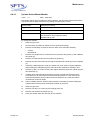
1
ICP
Service Manual
The information contained in this manual is applicable to the following system:
Handling System:
Process Module:
Software Release:
CPX / VPX and MPX / LPX
ICP
Release 2009 Vol.1 Build 1
Version 2.4
SPP Process Technology Systems UK Limited
Imperial Park
Newport
NP10 8UJ
UK
This Page is Intentionally Blank
Preliminary
This Page is Intentionally Blank
Table of Contents
P1
P2
P3
P4
P5
P6
P7
P8
P9
P10
P11
P12
P13
P14
P15
P16
P17
Version 1.4
Preface ....................................................................................................................... 5
About this Manual ..................................................................................................... 6
Assumptions ............................................................................................................. 7
Acknowledgements .................................................................................................. 8
Warnings, Cautions and Notes ................................................................................ 9
Safety Introduction ................................................................................................. 10
P6.1 Responsibilities ............................................................................................ 10
P6.2 Guide for a Safe Way To Work .................................................................... 11
General Safety ......................................................................................................... 12
P7.1 Actions in the Event of Fire or other Emergency .......................................... 12
P7.2 Hazardous Conditions .................................................................................. 12
P7.3 Hazardous Locations.................................................................................... 13
Personal Safety ....................................................................................................... 14
P8.1 Personal Protective Equipment .................................................................... 14
Specific Physical Hazards...................................................................................... 15
P9.1 Viton Synthetic Rubber and Fluoroelastomer Products................................ 15
P9.2 IPA................................................................................................................ 15
Mechanical Safety ................................................................................................... 17
Manual Handling ..................................................................................................... 18
Compressed Air ...................................................................................................... 19
P12.1 Pneumatic Isolation ...................................................................................... 19
Vacuum Pumps ....................................................................................................... 20
Electrical Safety ...................................................................................................... 21
P14.1 Radio Frequency (RF) Power....................................................................... 21
P14.2 Live Works.................................................................................................... 21
P14.3 Uninterruptible Power Supply (UPS) ............................................................ 22
P14.4 Electro-Magnetic Radiation .......................................................................... 22
P14.5 Laser Devices............................................................................................... 23
P14.6 Lock Off Procedure ...................................................................................... 24
P14.6.1 Mains Isolation .............................................................................. 24
P14.6.2 PDU / Electronics Rack Isolation .................................................. 24
Gas Safety................................................................................................................ 25
P15.1 General......................................................................................................... 25
P15.2 Discovering a Gas Leak ............................................................................... 25
P15.3 Treatment of Exhaust Gases........................................................................ 25
P15.4 Contamination of Components ..................................................................... 26
P15.5 Flammable Gases ........................................................................................ 26
P15.6 Gas Lines (Toxic and Non-toxic) .................................................................. 26
Hazardous Substances........................................................................................... 28
P16.1 Working with Hazardous Substances........................................................... 28
P16.2 Spillage of Hazardous Substances .............................................................. 28
P16.3 Additional Safety Notes ................................................................................ 28
P16.4 System Cleaning .......................................................................................... 29
P16.5 Unintended and Intended Releases ............................................................. 29
Disposal of SPTS Equipment................................................................................. 30
P17.1 Decommissioning and Disposal Process ..................................................... 30
P17.1.1 Hazardous Contamination List ...................................................... 30
P17.1.2 Areas of Contamination................................................................. 30
P17.1.3 Disposal ........................................................................................ 31
P17.2 Recycling ...................................................................................................... 32
P-3
Preliminary
Figures
P.1
Preliminary
Hazardous Locations .............................................................................. 13
P-4
Version 1.4
P1
Preface
Welcome to the service manual.
The manual is organised into chapters as follows:
Chapter 1 - Introduction
This chapter introduces the system, discusses its major components and summarises the
main features.
Chapter 2 - Control System and Power Distribution
This chapter details the control systems that govern all process operations, as well as detailing
the components that provide AC and DC power.
Chapter 3 - Manual Control and Software Utilities
This chapter describes how to manually control individual system devices (e.g. valves, MFCs,
pumps, etc.) and how to use the software utilities that enable troubleshooting of the system.
Chapter 4 - Maintenance
This chapter describes the periodic maintenance procedures as well as replacement
procedures and assembly instructions for common equipment items.
Version 1.4
P-5
Preliminary
P2
About this Manual
© This manual is protected by copyright and may not, in whole or part, be stored in a retrieval
system, or transmitted in any form, or by any means, copied, photocopied, translated or
reduced to any machine readable form without prior consent in writing from SPP Process
Technology Systems UK Limited.
Owing, in most part, to SPTS equipment being used by purchasers for their unique
applications, NO liability can be accepted for any inaccuracies or omissions in this publication,
although every possible care has been taken to make it as complete and accurate as possible.
SPP Process Technology Systems UK Limited reserves the right to make changes and alter
specifications without prior notice and without incurring an obligation to make changes to
products manufactured previously. You are advised to contact your nearest SPTS office for the
latest information on product improvements, incorporated after this publication.
All information contained in this manual is based on the latest product information available at
the time of publication. Graphics and illustrations in this publication are intended for reference
use only and may not depict actual machine configuration, or component parts.
All rights reserved, © 2009 SPP Process Technology Systems UK Limited
Preliminary
P-6
Version 1.4
P3
Assumptions
This manual has been produced to assist operators and system engineers to perform their
tasks safely and competently. SPP Process Technology Systems UK Limited has assumed
that personnel operating this equipment are fully conversant with all appropriate safety issues,
familiar with the technology the system represents, and are competent users of Windows
based computer operating systems.
Version 1.4
P-7
Preliminary
P4
Acknowledgements
All product names mentioned are acknowledged as the trademarks or registered trade marks
of their respective owners.
Preliminary
P-8
Version 1.4
P5
Warnings, Cautions and Notes
Warnings, Cautions and Notes are used throughout this manual. Warnings are highlighted by
use of an international hazard symbol. The following definitions of these notices are shown in
the way that they are presented in the manual.
WARNINGS
A warning is given to alert the user of possible hazards which may cause loss of life, physical
injury or ill health in any form. An example warning is shown below.
POTENTIALLY LETHAL VOLTAGES ARE PRESENT IN THIS EQUIPMENT. SWITCH OFF
AND ISOLATE ALL ELECTRICAL SUPPLIES BEFORE REMOVING ANY COVERS. TAKE
PRECAUTIONS AGAINST ELECTRIC SHOCK WHEN WORKING ON LIVE EQUIPMENT
WITH THE COVERS REMOVED.
Warnings can be considered to fall into two categories, those due to hazardous materials and
those due to hazardous operations. Where appropriate, a second international hazard symbol
is used for specific hazards.
CAUTIONS
A caution is given to alert of possible hazards which may cause damage to equipment. An
example caution is shown below.
CAUTION: Consult the safety procedures and carry out those that are necessary for
switching off the system.
NOTES
A Note is used to convey or draw attention to information that is extraneous to the immediate
subject of the text. An example note is shown below.
Note: The screens shown in this manual represent a “typical” machine, and may NOT
reflect the machine configuration exactly.
Version 1.4
P-9
Preliminary
P6
Safety Introduction
All the Safety precautions displayed in this chapter MUST be read and understood prior
to operating, maintaining or repairing the equipment.
Owing, in most part, to SPP Process Technology Systems UK Limited equipment being used
by customers for their own unique applications, the information contained in this section is
included as a guide ONLY.
It is recommended that ALL subsequent information contained in this chapter be used in
conjunction with the customers national, local and in-house safety procedures and policies.
NO liability can be accepted for any inaccuracies or omissions in this publication, although
every possible care has been taken to make it as complete and accurate as possible and
represent the minimum safety precautions to be taken.
This chapter also contains guidance about additional health and safety procedures applicable
to the equipment and its uses.
SPP Process Technology Systems UK Limited does not accept liability for any by-products
resulting from the customer’s application.
P6.1
Responsibilities
It is the responsibility of the service engineer/operator to be aware of:
•
•
This document
Their responsibilities and that they are provided with adequate resources to carry out
their job whilst complying with all health and safety requirements
It is the responsibility of the service engineer/operator to comply with these procedures and
with all local health and safety legislation.
Preliminary
P-10
Version 1.4
P6.2
Guide for a Safe Way To Work
1. Start
Plan the Task
Consider the Risks
Think about the
Dangers
Review environmental
conditions and
Hazards
Consider all the
appropriate Safety
Precautions
Familiarise yourself with all the relevant COSHH, MSDS and RAs
associated with the task.
Any local procedures related to this must be followed.
2. Preparation
Ensure the Work area
is Free of all
extraneous material
Ensure appropriate
Safety Clothing is
Worn
Assemble all necessary
tools and spare parts to
undertake the task
Ensure that all relevant
WARNING and
CAUTION safety
notices are clearly
displayed
Obtain permission to
undertake work on the
equipment from your
supervisor
Review the procedures
associated with the
task
3. Undertake the task
Work in a logical
sequence
4. Completion
On completion of the
task, test the system for
serviceability
When the work is
completed, inform the
supervisor. Complete
the required paperwork
Remove All safety
notices from the
equipment
Ensure the machine
and work area is free of
all extraneous material
Version 1.4
P-11
Preliminary
P7
General Safety
P7.1
Actions in the Event of Fire or other Emergency
•
•
•
•
P7.2
Hazardous Conditions
•
•
•
Preliminary
Service engineers/operators must familiarise themselves with local procedures for
raising and reacting to, fire, gas and any other alarms
In particular, location of alarm call points, emergency exits and assembly points,
various alarm sounds and roll call procedures must be known
Procedures for obtaining first aid assistance must be known
All of the above apply to procedures during and out of normal working hours
Service engineers/operators must be aware of, and act accordingly to, local conditions
of high magnetic fields, RF radiation, laser radiation, high or low temperature or
humidity
Service engineers/operators must be aware that substrate samples may be at elevated
temperatures after processing
Service engineers/operators must be aware that substrate samples may contain
substances hazardous to health
P-12
Version 1.4
P7.3
Hazardous Locations
Service engineers/operators must be aware of the following specific hazardous locations
Hazard
Location
Description
Inside AC Enclosure
High voltages are present within
the AC enclosure
Inside DC Enclosure
High voltages are present within
the DC enclosure
Electronics Rack AC
Distribution Panel
High voltages are present within
the electronic rack AC distribution
panel
Electronics Rack PLC Drawer
High voltages are present within
the E-Rack PLC drawer
Source Matching Units
High RF voltages are present
within the source matching units
Bias Decoupling Unit
High RF voltages are present
within the bias decoupling unit
Foreline
Hot surfaces are present on the
heated foreline
Lower RF Enclosure
Hot surfaces are present within
the lower RF enclosure
High Voltage
Hazard Label
High RF Voltage
Hot Surface
Hot surfaces are present within
the loadlock
Loadlock
(LPX only)
Cold Surface
Lower RF Enclosure
Cold surfaces are present within
the lower RF enclosure
Crush Hazard
Lower RF Enclosure
A crush hazard is present within
the lower RF enclosure
Non-Ionising
Radiation
Lower RF Enclosure
Non-Ionising radiation is present
within the lower RF enclosure
Strong Magnetic
Field
Source Enclosure
Strong magnetic fields are
present within the source covers
Laser
Loadlock
A class1 laser is present within
the loadlock
(MPX and MACS only)
Note: The gasbox will contain gases that are specific to each process requirement.
The actual hazard labels used will be dependant upon the gases present.
Corrosive /
Explosive /
Flammable/
Oxidising / Toxic
Gases
Corrosive / explosive / flammable
/ oxidising / toxic gases are
present within the equipment
located inside the gasbox
Gasbox
P.1
Version 1.4
Hazardous Locations
P-13
Preliminary
P8
Personal Safety
Before undertaking any maintenance or repair of the equipment, review the guide to a safe way
to work.
P8.1
Personal Protective Equipment
Provided the system is process contaminant free, routine maintenance can be undertaken
wearing a face mask, ‘double-gloved’ nitrile gloves and chemically resistant goggles that
comply with BS EN 166 and/or ANSI Z87.1.
WHEN THE SYSTEM CANNOT BE VENTED, THERE ARE STRICT PROCEDURES
THAT MUST BE FOLLOWED AND FULL PPE SUITABLE FOR DEALING WITH
HAZARDOUS GASES AND THEIR BY-PRODUCTS MUST BE WORN. PLEASE REFER
TO THE MSDS FOR DETAILS ON THE PPE AND CONTACT SPTS AS SOON AS
PRACTICABLE FOR INSTRUCTION.
ALL PPE MUST BE USED IN ACCORDANCE WITH THE MANUFACTURER’S
INSTRUCTIONS OR LOCAL PPE REQUIREMENTS.
BEFORE BREAKING SEALS AND UNDERTAKING AIR SAMPLING CHECKS, FULL
PERSONAL PROTECTIVE EQUIPMENT MUST BE WORN INCLUDING A
RESPIRATOR.
THE IMMEDIATE AREA MUST BE WELL VENTILATED. ALL NON-ESSENTIAL
PERSONNEL MUST BE EVACUATED TO A SAFE AREA AND AIR SAMPLING
WARNING NOTICES MUST BE DISPLAYED IN THE IMMEDIATE VICINITY.
WHEN UNDERTAKING AIR SAMPLING TESTS, CHECKS MUST BE MADE TO
ASCERTAIN THE CONCENTRATION OF RESIDUAL GASES AND HAZARDOUS BYPRODUCT GASES.
IT IS RECOMMENDED THAT MAINTENANCE PERSONNEL WEAR SAFETY
GOGGLES THAT CONFORM TO THE CURRENT LOCAL SAFETY STANDARDS OR
MINIMALLY TO BS EN 166 AND/OR ANSI Z87.1
Preliminary
P-14
Version 1.4
P9
Specific Physical Hazards
This section details the specific physical hazards that arise from materials used commonly in
all system applications. Other hazardous materials may also be present, for example
hazardous gases may be used for particular process requirements.
Always refer to the manufacturer’s MSDS information for each of these hazardous materials
before performing any maintenance or repair procedures.
P9.1
Viton Synthetic Rubber and Fluoroelastomer Products
SEVERE BURNS CAN RESULT FROM THE HANDLING OF VITON ‘O’-RINGS WHICH
HAVE BEEN EXPOSED TO EXCESSIVELY HIGH TEMPERATURES. HOWEVER,
SERVICE ENGINEERS ARE ASSURED THAT WHEN USED UNDER THEIR DESIGN
CONDITIONS THEY ARE SAFE.
Viton is a fluoroelastomer which is a synthetic rubber-like material containing fluorine. If this
material is exposed to temperatures in the region of 400°C or higher, the material decomposes
and one of the products formed is hydrofluoric acid. This is an extremely corrosive
substance and is almost impossible to remove once it contaminates the skin and first aid
assistance must be sought.
If it is required to inspect equipment which has been exposed to very high temperatures (e.g.
if it has been involved in a fire), examine closely to ascertain if any seals have suffered
decomposition, in which case they will appear charred.
If such indications are visible, do not touch the seals or the installation. Report the incident to
your safety officer who should arrange to decontaminate the area.
DO NOT TOUCH ANYTHING IN THE VICINITY OF THE DECOMPOSED MATERIAL
UNTIL IT HAS BEEN DECONTAMINATED.
Note: There is no such hazard for natural rubber Nitrile seals.
P9.2
IPA
IPA (Isopropyl Alcohol) is used for cleaning purposes.
Safe handling data applicable to Isopropyl Alcohol is as follows:
Manufacturer
Microchem Systems Ltd
Physical Data
Boiling point: 82 - 83°C.
Specific gravity: 0.785 - 0.786 (H2O=1).
Vapour pressure: 4100 Pa.
Solubility in water: Completely miscible in water at 20°C
Evaporation rate: 1.5.
Fire And Explosive Hazard Data
Highly Flammable
Flash point: 12°C.
Extinguishing medium: Alcohol-resistant foam, water spray or fog. Dry chemical powder,
carbon dioxide, sand or earth may be used for small fires only. Do NOT use water in a jet.
Special fire fighting procedures: Keep adjacent containers cool by spraying with water.
Version 1.4
P-15
Preliminary
Unusual fire and explosive hazards: Hazardous combustion products may include carbon
monoxide. The vapour is heavier than air, spreads along the ground and distant ignition is
possible.
Health Hazard Data
Skin: Wash skin with water using soap if available. If persistent irritation occurs, obtain medical
attention.
Eyes: Flush eye with water. Obtain immediate medical attention.
Inhalation: Remove to fresh air. If rapid recovery does not occur, obtain medical attention.
Ingestion: Do not induce vomiting. If rapid recovery does not occur, obtain medical attention.
Give water to drink, providing patient is conscious.
Incompatibility: Reacts with strong oxidising agents. Reacts with strong acids.
Spill Or Leak Procedures/Waste Disposal
Prevent contamination of soil and water. Prevent from spreading or entering into drains,
ditches or rivers by using sand, earth or other appropriate barriers.
Risk of explosion. Inform the emergency services if liquid enters surface water drains. Vapour
may form an explosive mixture with air.
Special Protection/Special Precautions
Avoid contact with eyes. Avoid prolonged or repeated contact with skin. Extinguish any naked
flames. Remove ignition sources. Avoid sparks. Do not smoke. Do not empty into drains. Earth
all equipment used for product transfer.
Preliminary
P-16
Version 1.4
P10
Mechanical Safety
MAINTENANCE AND REPAIR PROCEDURES MAY ONLY BE UNDERTAKEN BY
SPTS APPROVED TECHNICALLY QUALIFIED PERSONNEL WHO ARE FULLY
AWARE OF ALL RELEVANT SAFETY PRECAUTIONS.
ENSURE THE CHAMBER IS AT AMBIENT TEMPERATURE BEFORE OPENING.
WHEN A CHAMBER HAS BEEN PROCESSING WITH TOXIC GASES, OR HAS TOXIC
GASES CONNECTED, THE FOLLOWING SAFETY MEASURES SHOULD BE CARRIED
OUT BEFORE THE CHAMBER IS VENTED TO ATMOSPHERE.
1.
ENSURE THE GAS LINES HAVE BEEN PUMP PURGED AND BACK FILLED
WITH N2 BEFORE VENTING (see Chapter 4 for further information on purging
the gas lines).
2.
ENSURE ALL APPROPRIATE ANALYTICAL AND SAFETY EQUIPMENT IS
AVAILABLE AND IS USED AS NECESSARY.
3.
ENSURE THE CHAMBER IS IN A SAFE STATE TO BE VENTED. IF TOXIC
GASES ARE PRESENT AFTER VENTING, BREATHING APPARATUS MUST BE
WORN BEFORE OPENING THE CHAMBER.
IF A CLEANING RECIPE CANNOT BE RUN, OR IF TOXIC GASES HAVE BEEN USED
IN THE PROCESS CHAMBER THEN PPE MUST BE WORN BEFORE OPENING THE
CHAMBER (SEE P8).
THE GASBOX CONTAINS EQUIPMENT THAT MAY CONTAIN HAZARDOUS GASES.
ONLY SPTS APPROVED TECHNICALLY QUALIFIED PERSONNEL WHO ARE FULLY
AWARE OF ALL RELEVANT SAFETY PRECAUTIONS MAY OPEN THE GASBOX.
ENSURE THAT THE GASBOX EXTRACT IS RUNNING BEFORE OPENING THE
GASBOX DOOR.
ENSURE THE GASBOX DOOR IS CLOSED AND LOCKED DURING PROCESSING.
Version 1.4
P-17
Preliminary
P11
Manual Handling
•
•
•
•
Preliminary
All operations involving manual handling must be in accordance with the local manual
handling operations regulations
In particular all mechanical handling aids provided must be used
Handling without mechanical aids must be a last resort and is in any case forbidden for
any single person handling of any component weighing 25 kg or more
Care must be taken with any component awkwardly located, or with any component
which has any other potentially hazardous characteristics, such as high or low
temperature, sharp edges, etc.
P-18
Version 1.4
P12
Compressed Air
Many devices on the system are operated pneumatically.
EYE PROTECTION SHOULD BE WORN WHEN WORKING ON PNEUMATIC SYSTEMS
AS A LOOSE PIPE WHICH IS PRESSURISED MAY CAUSE EYE DAMAGE.
ALWAYS DIRECT COMPRESSED AIR AWAY FROM EYES AND SKIN.
Compressed air is safe when used correctly. However, open ended pipes must never be
brought into close contact with bare skin, since air may penetrate the skin and may form
embolisms in the bloodstream.
If compressed air is used for blowing away dust or swarf or for cooling purposes, then
appropriate eye protection must be worn to prevent particles of foreign matter from being blown
into the eyes.
Hoses, fittings, regulators, and valves should be inspected periodically for leaks, damage and
other defects.
P12.1
Pneumatic Isolation
Pneumatic isolation valves are located in the following areas:
Version 1.4
•
CPX / VPX systems
On the air preparation assembly located in the lower enclosure below the handler.
•
MPX systems
On the air preparation assembly located between the carousel and the process
module.
•
LPX systems
On the air preparation assembly located directly below the loadlock.
P-19
Preliminary
P13
Vacuum Pumps
Refer to the manufacturer’s instructions for all information on the safe operation of the pumping
equipment.
ENSURE THAT THE MANUFACTURER’S RECOMMENDATIONS FOR NITROGEN
PURGES ARE FOLLOWED BEFORE PERFORMING ANY SERVICE PROCEDURE ON
THE PUMPING EQUIPENT.
THE SYSTEM’S HELIUM SUPPLY MUST BE ISOLATED BEFORE STOPPING THE
LOCAL EXHAUST VENTILATION (LEV) SYSTEM.
Preliminary
P-20
Version 1.4
P14
Electrical Safety
TO PREVENT RISK OF INJURY, ALL MAINTENANCE AND REPAIR PROCEDURES
MUST BE UNDERTAKEN BY TECHNICALLY QUALIFIED PERSONNEL WHO ARE
FULLY AWARE OF ALL RELEVANT SAFETY PRECAUTIONS ASSOCIATED WITH
PROCESSING, OPERATING AND MAINTAINING THE EQUIPMENT. IN ADDITION,
SUCH PERSONS MUST BE CAPABLE OF OPERATING SPTS SOFTWARE.
POTENTIALLY LETHAL VOLTAGES (IN EXCESS OF 30 VOLTS AC AND 50 VOLTS
DC) ARE PRESENT ON THE EQUIPMENT. TO PREVENT INJURY, ENSURE THE
SYSTEM, CIRCUIT OR COMPONENT IS ISOLATED AND ‘LOCKED OFF’ FROM ITS
SOURCE OF SUPPLY PRIOR TO UNDERTAKING ANY MAINTENANCE OR REPAIR
OF THE EQUIPMENT. DO NOT RELY ON CONTROL SYSTEM INTERLOCKS OR VDU
DISPLAYS AS AN INDICATION THAT IT IS SAFE TO WORK ON POTENTIALLY
HAZARDOUS ITEMS.
WHEN UNDERTAKING ELECTRICAL MAINTENANCE AND REPAIR PROCEDURES,
NEVER WORK ALONE.
P14.1
Radio Frequency (RF) Power
The system uses RF power during processing. All enclosures inside which RF power is present
are clearly marked and the covers are fitted with electrical interlocks. Anyone requiring access
to the source must be fully aware of the hazards of RF power.
The relevant parts of the system must be electrically isolated before any work is carried out
inside these enclosures. Apart from the risk of electrical shock, severe burns are possible if live
conductors are touched.
All securing fasteners on RF panels should be refitted before using the system.
P14.2
Magnetic Fields
The source contains strong magnetic fields. Strong magnetic fields may cause pacemakers to
malfunction. Damage to magnetic-sensitive devices (bank/credit cards, watches, etc.) may
also result. Magnetic field strength is negligible at distances over 30cm from the source.
P14.3
Live Works
Whenever work is being carried out on live conductors, suitable warning notices should be
posted close to the machine to alert other people of the hazard. The machine should never be
left unattended. Live electrical work should never be carried out by a lone worker.
If electrical equipment is to be isolated using a breaker tripped to ‘off’ a DVM must be used to
ensure that the equipment is no longer energised.
Version 1.4
P-21
Preliminary
P14.4
Uninterruptible Power Supply (UPS)
On MPX and MACS systems an uninterruptible power supply (UPS) will continue to provide
power to specific areas of the loadlock after an emergency off (EMO) and / or after the main
breaker is off. The UPS is located in the enclosure underneath the loadlock.
The power is used to enable a current wafer transfer operation to complete and for the gate
valve to close thereby isolating the loadlock from the process module.
The areas that the UPS supplies power to are:
•
•
•
•
•
Loadlock PC
24V DC PSU (including carousel)
PC monitor
Cleanroom panel interface
Cleanroom panel adderlink (including KVM switch)
ALWAYS REFER TO THE POWER WIRING DIAGRAM FOR THE LOADLOCK SUPPLIED
IN THE DRAWING PACKAGE BEFORE PERFORMING ANY MAINTENANCE WORK ON
THE LOADLOCK
P14.5
Electro-Magnetic Radiation
To ensure that compliance with the electro-magnetic compatibility (EMC) directive is
maintained, all covers should remain correctly fitted and secured at all times except when their
removal is required for maintenance purposes. When refitting covers, ensure that they are
secured with a full complement of the fixing items (i.e. screws, clips, wire locking, etc.) with
which they were originally secured. Ensure that all earth leads are connected and all hardware
interlocks are operating correctly.
Non-ionising radiation is located in the source and upper & lower electrodes and has the
following properties:
Preliminary
Frequency
Power
Mode
Wavelength
13.56MHz
Upto 600W
Continuous
22.1m
380KHz
Upto 1KW
Continuous
788.9m
P-22
Version 1.4
P14.6
Laser Devices
The system makes use of laser devices to map substrates.
THE LASERS USED ARE CLASS 2 DEVICES. THIS CLASS IS SAFE FOR ACCIDENTAL
VIEWING UNDER ALL OPERATING CONDITIONS. HOWEVER THIS CLASS IS
CONSIDERED HAZARDOUS IF A PERSON STARES DIRECTLY INTO THE LASER
BEAM.
The following table provides details of the laser devices fitted to each handling system:
Handling System
Laser Details
CPX / VPX
Each VCE contains a laser for cassette mapping. Please refer to
the handler OEM documentation for details on the laser device.
MACS
A laser is located behind the carousel in front of the chamber gate
and is used to map the carousel and verify a substrate’s presence
or absence during handling. The laser data sheet is as follows:
Manufacturer: Omron, equipment model number: E3C-LD11,
Wavelength: 650nm, Power: 2.5mW max., FDA: Class II, JIS:
Class 2.
A laser is also located on the robot situated directly adjacent to
the carousel and is used to map the cassettes. Please refer to the
robot OEM documentation for details on the laser device.
MPX
A laser is located behind the carousel in front of the chamber
gate. The laser data sheet is as follows:
Manufacturer: Omron, equipment model number: E3C-LD11,
Wavelength: 650nm, Power: 2.5mW max., FDA: Class II, JIS:
Class 2.
LPX
The LPX system does not make use of laser devices.
In addition to this, lasers may be used for optional EPD purposes. In such cases please refer
to the EPD OEM documentation for details on the laser devices.
Version 1.4
P-23
Preliminary
P14.7
Lock Off Procedure
ELECTRICAL SUPPLIES AT VOLTAGES ABOVE 30 VOLTS AC AND 50 VOLTS
DC CAN KILL. BEFORE WORKING ON ANY OF THE SYSTEM’S ELECTRICAL
EQUIPMENT, ALWAYS SWITCH OFF THE SUPPLY AT THE CIRCUIT BREAKER
AND ENSURE IT IS LOCKED OFF.
TO PREVENT ANYONE FROM RE-CONNECTING THE SUPPLY, A SIGN
‘DANGER ELECTRICIAN AT WORK’ MUST BE DISPLAYED.
P14.7.1
Mains Isolation
Where practicable always isolate the power supply to the machine (equipment) at its mains
isolator.
P14.7.2
1.
Identify the mains isolator.
Refer to the Service Manual to ensure the correct isolator is identified.
2.
Place the isolator in the OFF position.
3.
Insert the lock-out and secure with a padlock.
4.
Remove the key and retain it.
5.
With the lock-out in place test the lockout to ensure that it prevents the isolator from
being moved to the ON position.
6.
If a lock-out clasp is already in place another lockout MUST be added to the clasp. The
lock-out clasp should have the facility for at least two padlocks to be fixed to it.
7.
Use a test lamp or DVM to ensure that the equipment is isolated.
8.
After maintenance has been completed, ensure that all guards and interlocks have
been replaced before removing the lockout.
PDU / Electronics Rack Isolation
If the power supply cannot be isolated at the mains isolator then the following procedure must
be followed:
Preliminary
1.
Identify the PDU / electronics rack that serves the tool.
2.
The PDU / electronics rack is fitted with a main circuit breaker and individual sub-circuit
breakers. Where practicable, the main circuit breaker should be locked-out. Only when
power is necessary on another part of the tool (e.g. to keep pumps running, etc.)
should a sub-circuit breaker isolation be made. Appropriate lock-out toggles MUST be
used to make isolations at the PDU / electronics rack.
3.
Place the isolator in the OFF position.
4.
Insert the lock-out and secure with a padlock.
5.
Remove the key and retain it.
6.
With the lock-out in place test the lockout to ensure that it prevents the isolator from
being moved to the ON position.
7.
If a lock-out clasp is already in place another lockout MUST be added to the clasp. The
lock-out clasp should have the facility for at least two padlocks to be fixed to it.
8.
Use a test lamp or DVM to ensure that the equipment is isolated.
9.
After maintenance has been completed, ensure that all guards and interlocks have
been replaced before removing the lockout.
P-24
Version 1.4
P15
Gas Safety
TO PREVENT INJURY, ALL MAINTENANCE AND REPAIR PROCEDURES MUST
BE UNDERTAKEN BY TECHNICALLY QUALIFIED PERSONNEL WHO ARE
FULLY AWARE OF ALL RELEVANT SAFETY PRECAUTIONS ASSOCIATED
WITH PROCESSING, OPERATING AND MAINTAINING THE EQUIPMENT. IN
ADDITION, SUCH PERSONS MUST BE CAPABLE OF OPERATING SPTS
SOFTWARE.
Surface Technology Systems plc. recommend that customers contact their local gas supplier
for all information about safety precautions and first aid treatment relating to the specific gases
used on their systems before connection.
P15.1
General
1.
P15.2
P15.3
Know the following:
1.1
The location of the nearest manual gas leak alarm call point.
1.2
The sound and sight of the gas leak alarm.
1.3
The boundaries of the gas risk area.
2.
On hearing the gas leak alarm, if you are in the gas risk area leave the gas risk area by
the nearest exit.
3.
Remain out of the gas risk area until it is safe to return.
4.
After a gas leak alarm be ready to carry out a full building evacuation if the fire alarm is
subsequently activated. In this event follow normal fire procedures.
Discovering a Gas Leak
1.
If the alarm has not already been activated by an automatic gas leak detection system,
sound the gas alarm.
2.
Leave the gas risk area by the nearest exit.
3.
Go to the designated assembly point and provide the incident personnel with as much
information as you can regarding the location and type of leak.
Treatment of Exhaust Gases
It is the customer’s responsibility to ensure exhaust gases from the backing pump are abated
in a manner that conforms to national and/or local environmental and safety regulations. The
following information is for guidance only.
There are three techniques for the treatment of harmful gases. Where more than one option is
available, the choice of technique should be that which minimises overall environmental
impact.
1.
Incineration/Oxidation
Most flammable gases can be readily oxidised either by passing them into a separately
fuelled flame or, in some instances, by passing them into a suitable oxidising chemical
reagent (solid or liquid). The properties of the resultant oxidised material (which may be
gaseous, liquid or solid) should be considered with a view to establishing further
treatment for environmentally appropriate disposal. Liquid and solid wastes may need
to be referred to specialist disposal contractors. Where the incineration process results
in the formation of particulate matter, further treatment in the form of filtration, water
spray or other techniques for removing particles from gas, should be used before
discharge of the gas to atmosphere or, if the gas remains an environmental hazard, the
next treatment process.
Version 1.4
P-25
Preliminary
2.
Chemical scrubbing
Some reactive gases can be absorbed by a suitable liquid or solid state chemical
scrubber. Designs can include scrubber liquid baths into which the waste gas is
bubbled; pumped scrubber liquor systems involving packed columns and/or spray
nozzles to improve gas/liquor contact; and packed solid reagent beds into which the
waste gas is passed. The chemical reagents used in all such equipment shall be
closely monitored to ensure continued efficiency. The ‘spent’ scrubber liquid, or solid,
will require disposal in an environmentally acceptable manner.
3.
Absorption
Some waste gases can be absorbed onto suitable materials, such as charcoal,
molecular sieve and chemically impregnated absorbent. These are often appropriate
for localised equipment or gas cabinet exhaust treatment, but usually still exhaust into
a main duct leading to a main scrubber to ensure absolute risk minimisation. Again,
‘spent’ cartridges must be correctly disposed to minimise environmental impact.
P15.4
Contamination of Components
Fluorocarbons will produce HF by-products and components in the gas train will become
contaminated. The exact nature of by-products will depend on the gases used, substrates and
processes. All parts of the system will have contamination, including the pumps and pump oil.
P15.5
Flammable Gases
Where flammable gases are used (the exhaust must be non-flammable), there is dilution of the
exhaust gases, which is controlled and monitored by the system’s N2 pump purge panel.
P15.6
Gas Lines (Toxic and Non-toxic)
WHEN A CHAMBER HAS BEEN PROCESSING WITH TOXIC GASES, OR HAS TOXIC
GASES CONNECTED, THE FOLLOWING SAFETY MEASURES SHOULD BE
CARRIED OUT BEFORE THE CHAMBER IS VENTED TO ATMOSPHERE.
Preliminary
1.
ENSURE THE CHAMBER IS IN A SAFE STATE TO BE VENTED. IF TOXIC
GASES ARE PRESENT AFTER VENTING, BREATHING APPARATUS MUST BE
WORN BEFORE OPENING THE CHAMBER.
2.
ENSURE THE GAS LINES HAVE BEEN PUMP PURGED AND BACK FILLED
WITH N2 BEFORE VENTING (see Chapter 3 for further information on purging
the gas lines).
3.
PROPER PURGING AND VENTING PROCEDURES MUST BE FOLLOWED
PRIOR TO OPENING THE CHAMBER TO ENSURE THAT ANY RESIDUE FROM
TOXIC PROCESS GASES AND THEIR BY-PRODUCTS HAVE BEEN REMOVED.
DUE TO THE HIGHLY TOXIC NATURE OF THESE RESIDUES, BREATHING
APPARATUS SHOULD ALWAYS BE WORN WHEN OPENING THE CHAMBER
UNLESS CHEMICAL SAMPLING IS CONDUCTED TO SHOW THE ABSENCE OF
ANY HAZARDOUS GASES AT CONCENTRATIONS ABOVE THE
OCCUPATIONAL EXPOSURE LIMIT (OEL).
4.
CHILLERS MUST BE SET AT AMBIENT TEMPERATURE BEFORE THE
CHAMBER IS OPENED TO AVOID THE OPERATOR BEING EXPOSED TO HOT
OR COLD SURFACES.
P-26
Version 1.4
EVACUATE HAZARDOUS GAS FROM THE GAS LINE AND BACK FILL THE GAS
LINE WITH N2 BEFORE COMMENCING A PROCESS CHAMBER CLEAN
PROCEDURE.
DECOMMISSION GAS LINES (HAZARDOUS AND NON HAZARDOUS) BEFORE
CARRYING OUT MAINTENANCE ON GAS LINES BETWEEN THE CUSTOMER
SUPPLIED GAS SOURCE ISOLATION VALVE AND THE GAS OUTLET VALVE TO THE
PROCESS CHAMBER.
WHEN UNDERTAKING MAINTENANCE ON HAZARDOUS AND NON-HAZARDOUS
GAS LINES, WARNING NOTICES MUST BE DISPLAYED TO IDENTIFY THE STATUS
OF SPECIFIC GAS LINE VALVES AND ASSOCIATED SOLENOID VALVES. WHEN
INDIVIDUAL GAS LINE VALVES ARE SHUT, THEY MUST BE LOCKED SHUT TO
PREVENT INADVERTENT OPERATION.
TO PREVENT AN UNCONTROLLED HAZARDOUS GAS FLOW TO THE PROCESS
CHAMBER, WHICH COULD RESULT IN PERSONAL INJURY, DO NOT OPEN THE BYPASS VALVE WHEN FLOWING A HAZARDOUS GAS.
TO PREVENT RISK OF PERSONNEL INJURY, THE HELIUM LEAK CHECK MUST BE
UNDERTAKEN BY SUITABLY QUALIFIED PERSONNEL WHO ARE FULLY AWARE OF
ALL RELEVANT SAFETY PRECAUTIONS ASSOCIATED WITH PROCESSING,
OPERATING AND MAINTAINING THE EQUIPMENT.
BEFORE UNDERTAKING HELIUM LEAK CHECK, CHECK THE STATUS OF THE
CHAMBER WITH THE SYSTEM’S PROCESS ENGINEER. SEEK GUIDANCE ON THE
APPROPRIATE CHAMBER CLEANING PROCESS TO RUN.
BEFORE UNDERTAKING AIR SAMPLING CHECKS, FULL PROTECTIVE CLOTHING
MUST BE WORN INCLUDING A RESPIRATOR. THE IMMEDIATE AREA MUST BE
WELL VENTILATED. ALL NON-ESSENTIAL PERSONNEL MUST BE EVACUATED TO
A SAFE AREA AND AIR SAMPLING WARNING NOTICES MUST BE DISPLAYED IN
THE IMMEDIATE VICINITY. WHEN UNDERTAKING AIR SAMPLING TESTS, CHECKS
MUST BE MADE TO ASCERTAIN THE CONCENTRATION OF RESIDUAL GASES AND
HAZARDOUS BY-PRODUCT GASES SUCH AS HCL AND HF.
Version 1.4
P-27
Preliminary
P16
Hazardous Substances
P16.1
Working with Hazardous Substances
•
•
•
•
•
P16.2
All work with any hazardous substance must be in accordance with the manufacturer’s
instructions, material safety data sheet (MSDS) and local regulations concerning the
control of substances hazardous to health
The substance’s MSDS must be consulted prior to the start of any work if the user is
not familiar with the hazardous material
Special care must be exercised with substances provided by the customer
It is the responsibility of the customer to ensure that any substance provided is suitable
for its intended purpose and is safe to use in that context
MSDSs must always be consulted for health and safety information for any substance
with which the service engineer is not completely familiar
Spillage of Hazardous Substances
If a spillage occurs:
•
•
•
•
•
•
•
•
•
•
P16.3
Additional Safety Notes
•
Preliminary
The manager of the area together with the environmental & safety manager must be
informed immediately and the area cleared of personnel depending on the liquid
released
PPE may be required. Collect the spillage kit and immediately surround the spillage
with the absorbent cloths, pillows, etc., until the spillage has been contained
Obtain the MSDS and read the section which relates to emergency release measures.
The MSDS will also give you the relevant information on the chemical make up of the
liquid
Clean up the spillage as quickly as possibly by following the instructions on the MSDS.
Further information can be obtained by speaking with the environmental & safety
manager
The MSDS will also inform you of what disposal methods may be required. Some
liquids do not mix with water and by adding water to dilute the spillage the following
may occur: fumes or an acidic liquid. NEVER add water to a liquid spillage unless you
have consulted the MSDS first
Using the correct PPE (As stated on the MSDS), clean up the contaminated absorbent
and place into the empty Spillage Kit
Label the spillage kit stating that the kit has been used for a liquid spillage. Together
with this place a copy of the MSDS onto the outside of the container
Inform site services as soon as the clean up procedure has been completed so they
can arrange for collection of the spillage kit into the designated holding area.
Remember to inform site services of the location of this used spillage kit
Inform the environmental & safety manager when the spillage has been dealt with so a
report can be created
When it is safe to re-enter the area inform this fact to the Manager of the area
To maintain cleanliness within the vacuum system and to prevent contamination,
corrosion, and reduce particulate levels; consideration must be given to preventing air
from coming into contact with gases or process by-products in the vacuum system.
This can be achieved by means of nitrogen purging, oxygen plasma cleans, etc.
P-28
Version 1.4
P16.4
System Cleaning
The actual cleaning procedure to follow is entirely process dependant. Please contact SPTS
for details on how to perform the mechanical clean.
•
•
•
P16.5
An etchback process must be run before any system cleaning takes place. This will
minimise the manual cleaning required
During the cleaning procedures, contaminated particulate material will created. All
appropriate safety precautions must be observed for this kind of hazard. Ensure that
contaminated material is disposed of in accordance with appropriate site policy and
procedures
Cleanroom wipes and abrasives will become contaminated during cleaning
procedures. Ensure that contaminated wipes and abrasives are placed inside a clearly
labelled bag and disposed of in accordance with appropriate site policy and procedures
Unintended and Intended Releases
The system is designed to operate at negative pressures, consequently any leaks will usually
be ‘in to’ not ‘out of’ the system. These ingresses will therefore be pumped away by the
pumping system to the customer’s local exhaust ventilation (LEV) system.
Should an over-pressure condition occur in the process module, an over-pressure relief valve
rated at 5psig will release gas through the gasbox to the customer’s local exhaust ventilation
(LEV) system.
The system does not produce intentional releases. After processing, all waste products are
pumped away by the pumping system to the customer’s local exhaust ventilation (LEV)
system.
Version 1.4
P-29
Preliminary
P17
Disposal of SPTS Equipment
SPTS tools may make use of hazardous substances, gases and liquids during the processing
of semiconductor substrates. Also, the residues that may be produced during processing can
be hazardous. The exact chemistry of the hazards will depend on:
•
•
•
Process chemicals
Wafer type and composition
Process conditions.
SPTS is not responsible for the decommissioning and disposal of its products. Furthermore,
SPTS is not a specialist in the disposal of hazardous chemicals and their by-products used on
or created by its goods. It is the user’s responsibility to make certain that appropriate licensed
disposal authorities and/or contractors are consulted to ensure that the disposal of the tool is
in line with local safety and environmental laws.
When decommissioning the system, particular attention should be paid to those areas of the
tool that may contain hazardous materials or by-products. These are typically going to be:
•
•
•
P17.1
Gas delivery system
Process chamber
Pumping system
Decommissioning and Disposal Process
SPTS is not responsible for making any recommendation for the decommissioning or disposal
of the facilities to the tool. These are wholly the user’s responsibility.
P17.1.1
Hazardous Contamination List
When planning the decommissioning and disposal of an SPTS plasma-processing tool, a
consideration must be made of all the process gases, liquids and their associated by-products
that have been used and/or created during the tool’s lifetime. SPTS recommends creating and
maintaining a list of the following:
•
•
All the process gases and fluids used during processing
All the possible by-products that may have formed and passed through the pumping
line
An example of such a table for a typical etch chamber is shown below:
Typical Inputs
Typical Contaminates
Form
For GaAs etching:
HCl, As, GaCl3, B2O3, AsCl3, CN, GaBr3, As,
AsH3, AsBr3
Solid / Gas
HCl, P, InCl3, PCl3, SiCl4, InBr, P, PH3
Solid / Gas
GaCl3, SiCl4.
Gas
HF, S variants, SO, SO2, CO, CO2
Solid / Gas
BCl3, Cl2, HBr, N2
For InP etching:
N2, Cl2, HBr, N2
For GaN etching:
Cl2,Ar, He
For Si etching:
SF6, O2, C4F8
The site health & safety advisor’s input should be sought to ensure that local and national
regulations relating to the disposal of the potential by-products are complied with, where there
are specific chemicals and by-products identified. No work should take place until a complete
plan for decommissioning and disposal is completed, including the identification of specialist
contractors who may be required to ensure that there is no exposure risk to site workers.
Preliminary
P-30
Version 1.4
P17.1.2
Areas of Contamination
DI Water and Town Water
The SPTS tool does not contaminate the cooling water during use. Disposal of any fluids left
in the tool should be in line with local practice.
Chiller Fluids (excluding DI water)
MSDS for these fluids (Syltherm XLT, Galden, DI ethanol mixtures, etc.) are provided with the
tool. The disposal instructions contained in the MSDS should be followed when these products
are drained from the tool. Chillers should then be disposed of, in line with local regulations, as
recommended in the OEM manuals.
Process Chamber
The process chamber is likely to have significant contamination following processes that may
be of a hazardous nature. The full decommissioning process should include:
•
•
•
•
P17.1.3
30 minute etchback process or whatever duration is required by process flow to
achieve a clean chamber
Full chamber clean
Isolation and pump out of gas lines
To include a minimum of five pump purge cycles followed by a minimum pump out
period of 24Hrs (see Chapter 3)
Power down of the tool
Disposal
Gas supply system
Following decommissioning, the gas lines should not contain residues that will cause exposure
over the TLV. However, a specialist contractor should be consulted to ensure that the
decommissioning procedure used will meet the minimum requirements for disposal of the
pipework and valves.
Process chambers
Following decommissioning, the process chamber should not contain residues that will cause
exposure over the TLV. However, a specialist contractor should be consulted to ensure that
the decommissioning procedure used will meet the minimum requirements for the chamber’s
disposal.
Pumping system
The turbo molecular pump (if fitted), APC, HiVac, foreline and backing pump may contain a
build up of process residues that may be toxic or corrosive and therefore represent a contact
or vapour hazard. Some residues may react when exposed to atmospheric moisture. Local
procedures or those of a specialist contractor should be consulted before creating the
decommissioning and disposal plan. Some residues will require disposal within a time limit
after breaking vacuum, or immediate sealing in appropriate containers for later
decontamination and disposal. Pumps should be decontaminated and disposed of as
described in the manufacturer’s recommendations and in line with local practice, as directed
by local policy.
OEM Equipment
All valves that are contacted by process chemicals should be dealt with as directed above.
All OEMs (and other components) that are contacted by cooling fluids represent no hazard and
require no special precautions. Disposal should be in line with local regulations.
Version 1.4
P-31
Preliminary
Electrical Items
SPTS tools are exempt from the RoHS directive. However all Pro tools manufactured after
December 2006 use RoHS compliant components and many OEM components used on the
tool before this date were already compliant. If there is any doubt, the OEM manufacturer
should be consulted.
Before selling on any electrical equipment it is the responsibility of the user to ensure that these
products are safe and in an appropriate condition for resale. SPTS accepts no liability for the
forward sale of components used on its tools, or warranty on them.
P17.2
Recycling
SPTS equipment is comprised of the following materials:
Group
Material
Panelling
Mild Steel (Painted)
Chamber Components
Aluminium 6082, 5083 / Stainless Steel 316L, 304 / FKM / FFKM
/ Nickel
Chamber Block
Aluminium 6082
Frame
Mild Steel (Painted)
Ceramics
Alumina / Aluminium Nitride
Conductors
Copper
Electrical Isolators
Tufnol / PTFE / PEEK
General Plastics
Nylon / Polypropylene / PVC
Recycling can only apply to those assemblies and components that have not been
contaminated or have been cleaned in accordance with local laws. A specialist contractor
should be consulted to ensure that any contaminated materials have been cleaned sufficiently
for recycling purposes.
Preliminary
P-32
Version 1.4
Chapter 1
Introduction
This Page is Intentionally Blank
Introduction
Table of Contents
1.1 Introduction ............................................................................................................... 6
1.2 System Overview ...................................................................................................... 7
1.2.1 Substrate Processing ..................................................................................... 9
1.3 Process Module....................................................................................................... 10
1.3.1 Source Assembly ......................................................................................... 11
1.3.1.1 Source Enclosure.......................................................................... 11
1.3.1.2 Coil Matching Unit ......................................................................... 11
1.3.2 Lower Chamber ............................................................................................ 11
1.3.3 Electrode Assembly...................................................................................... 11
1.3.3.1 Platen ............................................................................................ 12
1.3.3.2 Lift Assemblies .............................................................................. 12
1.3.4 External Components ................................................................................... 13
1.3.4.1 Combined APC/HiVac Valve......................................................... 13
1.3.4.2 HiVac Gauge................................................................................. 13
1.3.4.3 Process Pressure Gauge .............................................................. 13
1.3.4.4 Roughing Gauge ........................................................................... 13
1.3.4.5 Over Pressure Switch ................................................................... 13
1.3.4.6 Atmosphere Switch ....................................................................... 13
1.3.4.7 Over Pressure Check Valve.......................................................... 13
1.3.4.8 Process Module Wall Heaters....................................................... 14
1.3.4.9 Anti-condensation Measures......................................................... 14
1.3.4.10 End Point Detection ...................................................................... 14
1.3.5 Frame ........................................................................................................... 14
1.3.6 RF Generators.............................................................................................. 14
1.3.6.1 Source RF Generator.................................................................... 14
1.3.6.2 Platen RF Generator ..................................................................... 14
1.3.7 Gasbox ......................................................................................................... 15
1.3.7.1 Gasbox Door Interlock .................................................................. 15
1.3.7.2 Gasbox Extract Sensor ................................................................. 16
1.3.8 Electronics Rack........................................................................................... 17
1.3.9 Power Distribution Unit ................................................................................. 18
1.4 Tool Control............................................................................................................. 19
1.4.1 Operator Station Interface ............................................................................ 20
1.4.2 Industrial PC ................................................................................................. 21
1.4.3 Control Logic Programmable Logic Controller (PLC) ................................... 21
1.4.3.1 555 Logix Controller ...................................................................... 21
1.4.3.2 Ethernet Card................................................................................ 21
1.4.3.3 DeviceNet Card............................................................................. 21
1.4.4 System Nodes .............................................................................................. 22
1.4.4.1 Optional Nodes ............................................................................. 23
1.4.5 I/O Bus Terminals......................................................................................... 24
1.4.5.1 Bus Coupler .................................................................................. 24
1.4.5.2 I/O Slices....................................................................................... 25
1.4.6 Valve Islands ................................................................................................ 25
1.4.6.1 SMC Valve Island.......................................................................... 26
1.4.6.2 Norgren Valve Island..................................................................... 26
1.5 Pumping System ..................................................................................................... 27
1.5.1 Turbo Pump.................................................................................................. 28
1.5.2 Backing Pumps ............................................................................................ 28
1.5.3 Pumping Procedure...................................................................................... 28
1.6 Cooling and Heating Systems ............................................................................... 29
1.6.1 Cooling System ............................................................................................ 29
1.6.1.1 Chillers .......................................................................................... 30
1.6.2 Heating System ............................................................................................ 30
1.7 System Pneumatics ................................................................................................ 31
Version 2.4
1-3
Service Manual
Introduction
1.7.1 Gasbox Valve Island .................................................................................... 32
1.7.2 Chamber Valve Island .................................................................................. 33
1.7.3 Chamber Pneumatic Schematic................................................................... 34
1.8 Vacuum System ...................................................................................................... 35
1.9 Service Connection Overview ............................................................................... 36
1.9.1 Service Panel ............................................................................................... 36
Service Manual
1-4
Version 2.4
Introduction
Figures
Figure 1.1
Figure 1.2
Figure 1.3
Figure 1.4
Figure 1.5
Figure 1.6
Figure 1.7
Figure 1.8
Figure 1.9
Figure 1.10
Figure 1.11
Figure 1.12
Figure 1.13
Figure 1.14
Figure 1.15
Figure 1.16
Figure 1.17
Figure 1.18
Figure 1.19
Figure 1.20
Figure 1.21
Figure 1.22
Figure 1.23
Figure 1.24
Figure 1.25
Figure 1.26
Figure 1.27
Figure 1.28
Figure 1.29
Figure 1.30
Figure 1.31
Figure 1.32
Version 2.4
System Overview ...................................................................................... 6
CPX System Layout Example................................................................... 7
VPX System Layout Example ................................................................... 8
MPX System Layout Example .................................................................. 8
Process Module Assembly...................................................................... 10
Source Assembly .................................................................................... 11
Gasbox Valve Arrangement.................................................................... 15
Gasbox Door Switch ............................................................................... 15
Gasbox Extract Sensor ........................................................................... 16
Electronics Rack (Typical Arrangement)................................................. 17
PDU - Typical Arrangement .................................................................... 18
Control System Layout............................................................................ 19
Operator Station Interface....................................................................... 20
Example Control Screen ......................................................................... 20
Control Logix PLC................................................................................... 21
ICP Node Layout Schematic................................................................... 22
Example Bus Terminal............................................................................ 24
Bus Coupler ............................................................................................ 24
Example I/O Slice ................................................................................... 25
SMC Valve Island ................................................................................... 26
Norgren Valve Island .............................................................................. 26
MPX Pumping Schematic ....................................................................... 27
CPX/VPX Pumping Schematic ............................................................... 27
Typical Backing Pump ............................................................................ 28
System Coolant Schematic..................................................................... 29
Example Heater/Chiller ........................................................................... 30
System Pneumatics ................................................................................ 31
Gasbox Valve Island ............................................................................... 32
Chamber Valve Island............................................................................. 33
Chamber Pneumatic Schematic ............................................................. 34
Vacuum Schematic ................................................................................. 35
Service Panel.......................................................................................... 36
1-5
Service Manual
Introduction
1.1
Introduction
This manual is intended to provide service and operator information to qualified STS trained
service personnel.
TO PREVENT RISK OF INJURY, ALL MAINTENANCE AND REPAIR PROCEDURES
MUST BE UNDERTAKEN BY TECHNICALLY QUALIFIED PERSONNEL WHO ARE
FULLY AWARE OF ALL RELEVANT SAFETY PRECAUTIONS ASSOCIATED WITH
PROCESSING, OPERATING AND MAINTAINING THE EQUIPMENT. IN ADDITION,
SUCH PERSONS MUST BE CAPABLE OF OPERATING SURFACE TECHNOLOGY
SYSTEMS (STS) SOFTWARE.
This manual has been prepared to provide service engineers and maintenance personnel with
the following:
•
•
•
•
A system introduction
Control system overview and manual control system operation
Description of the mechanical assemblies
Maintenance procedures
Figure 1.1
Service Manual
1-6
System Overview
Version 2.4
Introduction
1.2
System Overview
The system consists of the following components:
•
•
•
•
•
•
•
•
•
PLC Control System
Process Chamber
Electronics Rack Including the Power Distribution System
Pumping System
Compressed Air Distribution System
Gas Supply System
Heaters/Chillers
RF Supplies
Handling/Transport System
Examples of possible system components and related equipment are shown below:
Figure 1.2
Version 2.4
CPX System Layout Example
1-7
Service Manual
Introduction
Service Manual
Figure 1.3
VPX System Layout Example
Figure 1.4
MPX System Layout Example
1-8
Version 2.4
Introduction
1.2.1
Substrate Processing
Once a substrate has been loaded, the substrate platen is raised to process height and the
substrate is clamped to the substrate platen by electrostatic attraction/weighted clamp. The
helium backside cooling (HBC) circuit then applies helium to the rear of the substrate at a predefined pressure before the flow of process gases is started.
After a user defined period for gas stabilisation, the R.F. comes on to start substrate
processing. Processing continues until either the pre-set R.F. excitation time is reached or the
end point detection (EPD) system detects a finishing point. The flow of process gases stops,
the helium backside cooling is switched off (and pumped out) and the clamping is removed.
The substrate platen is lowered and the process chamber is pumped down to base pressure.
Version 2.4
1-9
Service Manual
Introduction
1.3
Process Module
The process module assembly is shown in Figure 1.5. Its principal functional components are:
•
•
•
•
•
Source Assembly
Gasbox
Lower Chamber
Electrode Assembly
External Components (not shown)
Gasbox
Source Assembly
Lower Chamber
Electrode Assembly
Figure 1.5
Service Manual
Process Module Assembly
1-10
Version 2.4
Introduction
1.3.1
Source Assembly
The source assembly consists of a plasma source enclosure and a coil matching unit.
Under PLC control, process gases are introduced to the chamber under vacuum conditions. A
plasma is then struck and maintained at 13.56MHz RF whilst the processing occurs. The coil
matching unit maintains maximum power transfer to maintain optimum process conditions.
Temperature controlled heaters are used within the source assembly to maintain process
stability.
Source Enclosure
Coil Matching Unit
Figure 1.6
1.3.1.1
Source Assembly
Source Enclosure
The source enclosure forms the upper half of the source assembly and contains the ceramics,
RF generating coils and solenoids. It also houses a cable heater and has a view port located
on the top. End point detection systems can be attached to the top of the source enclosure to
make use of the view port.
1.3.1.2
Coil Matching Unit
The coil matching unit (CMU) is used to impedance match the RF source with that of the
process chamber. The unit contains three stepper motor driven capacitors that are rapidly
tuned to maintain optimal power transfer.
Temperature control of the CMU is regulated by internal electrical fans.
1.3.2
Lower Chamber
The lower chamber, which is manufactured from a single block of aluminium, contains two
openings are located on opposite sides near the top of the chamber. One provides access to
the substrate platen for the transport module. The other is a port connecting to a combined
automatic pressure control valve/HiVac valve and a vacuum pumping system.
1.3.3
Electrode Assembly
The electrode assembly is housed within the lower chamber and is comprised of the platen and
lift assemblies.
Version 2.4
1-11
Service Manual
Introduction
1.3.3.1
Platen
The platen consists of the electrode block which is connected to RF power, fluid cooling and
helium back cooling supplies. If an electrostatic clamping system is fitted, a high voltage DC
supply is connected through the electrode to the electrostatic chuck. The substrate platen is
supported on a stainless steel bellows and is connected to the electrode lift assembly, which
is used to raise it to the process level. The flexible bellows, which is differentially pumped, sits
on an adapter which is secured to the process module base plate.
1.3.3.2
Lift Assemblies
There are two lifts located in the RF chamber below the process module. The substrate lift is
used to raise/lower the substrate from/to the robot arm during loading and unloading. The
platen lift is used to raise the platen to processing height. Each of the lift assemblies are
comprised of an air cylinder and piston arrangement. The electrode lift assemblies are partly
contained in the bottom RF enclosure with their air cylinders beneath this in the frame. The
platen lift height is controlled by stops and is dependant on process height requirements.
Service Manual
1-12
Version 2.4
Introduction
1.3.4
External Components
The process chamber external components consist of the following:
•
•
•
•
•
•
•
•
•
1.3.4.1
Combined APC/HiVac valve
HiVac gauge
Process pressure gauge
Vacuum switch
Atmosphere switch
Burst pressure kit
Process module wall heaters
Anti-condensation measures (optional)
End point detection system (optional)
Combined APC/HiVac Valve
The combined automatic pressure controller/high vacuum (APC/HiVac) valve is located at the
back of the process chamber. It sits directly between the process chamber and turbo pump.
The valve acts in two ways: As an on/off isolation valve isolating the turbo from the process
chamber and as a throttle valve, varying its opening to maintain the required process pressure.
The APC valve can operate in either manual or automatic mode depending on the selection
made in the recipe editor. In manual mode, a percentage valve ‘open’ from 100 to 0%
corresponding to an angle of opening between 0.1 and 90 degrees can be selected. In
automatic mode, the angle is pressure dependent. The valve opens and closed automatically
to maintain the pressure set in the recipe editor under the control of a pressure controller.
1.3.4.2
HiVac Gauge
An active inverted magnatron (AIM) gauge is used to measure the process module base
pressure. It generally operates in the range 1x10⁻² to 1x10⁻⁶ Torr.
1.3.4.3
Process Pressure Gauge
A capacitance manometer is used to measure the process pressure. This gauge is isolated
from the process chamber for pressures outside the gauge’s range (e.g. during venting, etc.).
The actual gauge fitted will vary for different process pressure requirements.
1.3.4.4
Roughing Gauge
The roughing gauge is used to measure chamber pressures up to 10 Torr. Output from this
gauge is used by the software to control the APC/HiVAC valve thereby protecting the turbo
from over pressure conditions.
1.3.4.5
Over Pressure Switch
An over pressure switch is used as a safety interlock in the 24V DC supply to the gasbox
solenoid. If the pressure exceeds 3.7 Torr, the pressure switch operates cutting off the process
gas supply to the process module. It operates in a fail-safe mode.
1.3.4.6
Atmosphere Switch
The atmosphere pressure switch is used by the control system to terminate the vent to
atmosphere sequence. It also acts to prevent electrostatic clamping (if fitted) when the process
chamber is at atmosphere.
1.3.4.7
Over Pressure Check Valve
An over pressure check valve is used to protect the process module against over pressure
during venting. It is rated at 5 psig. The extract is fed into the gasbox extract for safety.
Version 2.4
1-13
Service Manual
Introduction
1.3.4.8
Process Module Wall Heaters
Heaters are located in the magnetic confinement chamber, the lower chamber and the upper
section of the source so as to keep plasma facing surfaces at temperatures suited to the
required process.
1.3.4.9
Anti-condensation Measures
Nitrogen is supplied to the lower electrode RF enclosure to prevent condensation damage.
When the chiller temperature drops below 10oC an electrically operated solenoid releases N2
into the lower electrode RF enclosure. The flow of N2 continues until the chiller temperature
rises above 20oC.
1.3.4.10
End Point Detection
The process module can accommodate various types of end point detection systems
including:
•
•
•
1.3.5
Single Frequency Optical Emission Spectroscopy (OES)
Scanning OES
Laser Interferometry
Frame
The frame is used to support the process chamber and enclose the electrode lift air cylinders.
The frame design complies with SEMI MESC and E25 standards.
1.3.6
RF Generators
The RF generators are used in conjunction with the process gases to produce a plasma that
is inductively coupled at 13.56 MHz via a matching unit and coil assembly located outside the
process module. This provides a high-density plasma capable of operating in a very wide
process range. Two RF generators are used, one for the source and one for the platen bias.
1.3.6.1
Source RF Generator
The source RF generator’s controls and indicators are described in the manufacturer’s
literature.
1.3.6.2
Platen RF Generator
The platen RF generator’s output is adjustable and its controls and indicators are described in
the manufacturer’s literature.
Note: There is an optional low frequency RF bias generator available for processes that
require SOI etching. This generator is coupled at 380KHz RF and is applied in pulses
defined by a pulse generator. The pulse generator is a Beckhoff slice within the
chamber I/O inside the DC panel.
Service Manual
1-14
Version 2.4
Introduction
1.3.7
Gasbox
The gasbox receives the process and purge gases and distributes them to the process
chamber. Flow rates for the process gases are controlled by dedicated mass flow controllers
(MFCs), which are in turn controlled via the I/O bus terminal located at the back of the gasbox.
Figure 1.7
1.3.7.1
Gasbox Valve Arrangement
Gasbox Door Interlock
The gasbox contains a mechanical door switch located at the lower right hand side of the
enclosure. This switch forms part of the software gasbox interlock and detects when the
gasbox door is open. When the door is open, the gasbox door software interlock is broken and
processing will be prevented.
Door Switch
Figure 1.8
Version 2.4
1-15
Gasbox Door Switch
Service Manual
Introduction
1.3.7.2
Gasbox Extract Sensor
A differential pressure sensor is used to ensure that gasbox extraction is present. Gasbox
pressure is measured near the sensor display at the bottom of the gasbox and also at the
extract point. Should the pressure differential between these two points fall below a preset
value, the gasbox extract software interlock will be broken and processing will be prevented.
Extract Point
Sensor Display
Figure 1.9
Service Manual
1-16
Gasbox Extract Sensor
Version 2.4
Introduction
1.3.8
Electronics Rack
The electronics rack houses the following equipment:
•
•
•
•
•
•
Power Distribution (see Chapter 2)
PLC Drawer
Electromagnet Power supply
LF & HF Platen Generators (see 1.3.6)
Source HF Generator (see 1.3.6)
End Point Detector PC (option)
EPD PC (Optional)
User PC (LPX Only)
Power Distribution
PLC Drawer
Electromagnet Power Supply
LF & HF Platen Generators
Source HF Generator
Figure 1.10
Version 2.4
Electronics Rack (Typical Arrangement)
1-17
Service Manual
Introduction
1.3.9
Power Distribution Unit
VPX
2 to 3
YES
VPX
1
OPTIONAL
MPX
1
NO
MACS
1
NO
LPX
1
NO
CB1
CB12
YES
SPD1
1 to 4
CB16
CPX
CB15
PDU Used?
CB14
No. of Process Modules
CB13
System
XL1
Certain system configurations require the use of a power distribution unit (PDU) To route
power to each process module’s electronics rack. The following table details the various
system configurations and shows where a PDU is used:
CB6
CB2
CB7
CB3
CB8
CB4
CB9
CB5
CB10
CB11
Figure 1.11
PDU - Typical Arrangement
See Chapter 2 for further information on the PDU.
Service Manual
1-18
Version 2.4
Introduction
1.4
Tool Control
The tool control system consists of an operator interface (with an optional touch screen), an
industrial computer, a control logix PLC and a series of bus terminals. Operational commands
are issued via the operator interface to the PC. This in turn controls the PLC which commands
each node of the DeviceNet network.
Figure 1.12
Version 2.4
1-19
Control System Layout
Service Manual
Introduction
1.4.1
Operator Station Interface
The operator station interface consists of a monitor, keyboard and mouse located on the CTC
cabinet (CPX/VPX) or a stand alone table (MPX/LPX). An optional touchscreen interface can
be mounted in the cleanroom wall.
Operator Interface CPX / VPX
Operator Interface MPX
Figure 1.13
Operator Interface
Cleanroom Panel
(Typical)
Operator Station Interface
The interface operates a Windows 2000 or XP environment, via an RS Logix software
interface. Information is displayed on the screen in accordance with the SEMI E95 standard
for Human Interface Design. An example screen is shown below:
Figure 1.14
Example Control Screen
If two control stations are fitted, the system can be controlled from either of the operator
stations (selected by means of a KVM switch), but not from both simultaneously. Control of the
Service Manual
1-20
Version 2.4
Introduction
system is achieved by setting the desired operator station as the master, with the other station
automatically defaulting to slave.
Note: If the system is currently performing an operation, e.g. a substrate transfer, the
system will wait until the operation is completed until an exchange of control is
allowed.
1.4.2
Industrial PC
Operator input from the operator station is fed to an industrial PC located within the CTC
cabinet (CPX/VPX) or loadlock (MPX), running the RS Logix Software.
1.4.3
Control Logic Programmable Logic Controller (PLC)
The Control logic PLC is located in a drawer in the electronics rack. The PLC consists of the
following components:
•
•
•
•
Power Supply
555 Logix Controller
Ethernet Card
DeviceNet Card
DeviceNet
Card
Power Supply
555 Logix
Controller
Ethernet Card
Figure 1.15
Control Logix PLC
The control system is explained in greater detail later in this manual.
1.4.3.1
555 Logix Controller
The Logix controller provides the central control for the system. The unit controls I/O located
on nodes throughout the system.
1.4.3.2
Ethernet Card
The ethernet card allows the PLC to communicate with the industrial PC.
1.4.3.3
DeviceNet Card
The DeviceNet card allows the PLC to communicate with the system nodes.
Note: A Multi Vendor Interface (MVI) card may be fitted to provide a serial interface
between the PLC and an EPD system and/or the handling system (MPX only).
Version 2.4
1-21
Service Manual
Introduction
1.4.4
System Nodes
The control PLC controls I/O located in a number of nodes situated around the system, linked
by a DeviceNet connection.
The location and description of the nodes is as shown below:
Figure 1.16
Service Manual
ICP Node Layout Schematic
Node
Number
Name
Description
00
PLC
Allen Bradley PLC
01
I/O
Pumping and lower electrode generator
control
02
Source Generator
Top electrode RF generator
03
Heater Controller
Chamber heater control
04
I/O
Chamber gauges, Interlocks, venting and
status monitoring.
05
VAT Valve Control
Combined APC/gate valve control
07
I/O
MFC Control
08
Valve Island
Gasbox pneumatic control
09
Platen Chiller
Lower electrode chiller control
10
Source Chiller
Upper electrode chiller control
1-22
Version 2.4
Introduction
1.4.4.1
Optional Nodes
The following nodes may be located on the system depending on the configuration:
Version 2.4
Node
Number
Name
Description
16
Fast Matching Unit
The fast matching unit is an optional
system addition which allows faster
matching times and aids in allowing
faster switching times
1-23
Service Manual
Introduction
1.4.5
I/O Bus Terminals
Each of the system nodes consists of an I/O pod, a valve island or a Beckhoff fieldbus
DeviceNet interfaced bus terminal.
Each bus terminal consists of the following:
•
•
•
Bus Coupler
I/O Slices
End Terminal / Terminator
Figure 1.17
1.4.5.1
Example Bus Terminal
Bus Coupler
Each I/O bus terminal or node contains a bus coupler as shown below:
Power LEDs
Fieldbus Connection
K-Bus
Bus Coupler Supply
Input For
Power Contacts
Address Selector
Power Contacts
Configuration Interface
Figure 1.18
Bus Coupler
The bus coupler provides the interface between the Logix PLC and the I/O bus terminal
controlling the actuators and monitoring the sensors. The bus coupler provides power for all
the I/O slices and feeds the data to and from the PLC via the K-Bus connection.
The unit also incorporates an address selector, which allows the secondary address and the
BAUD rate to be selected.
Service Manual
1-24
Version 2.4
Introduction
1.4.5.2
I/O Slices
Each node or bus terminal has a number of I/O slices located within it. An example is as shown
below:
Signal LED 1
Figure 1.19
Signal LED 2
Example I/O Slice
Each bus terminal consists of a number of I/O slices, including analogue in and out, digital in
and out and relays. Each I/O slice has indicator LEDs as shown in Figure 1.19. These LEDs
are used to indicate how the I/O slice is operating. Analogue I/O LEDs are constantly
illuminated whereas the relay and digital I/O LEDs are illuminated when the required signal is
being sent or received. Each of the I/O slices are ‘hot swappable’, i.e. a damaged card can be
replaced without power being removed from the bus terminal.
The I/O cards consist of either a digital in, digital out, analogue in, analogue out or relay card.
Each bus terminal will have an end terminal located on it, which identifies the end of the bus
terminal to the PLC.
1.4.6
Valve Islands
There are two PLC controlled valve islands located on the system used to operate the various
pneumatic valves on the system. They are:
•
•
Version 2.4
SMC SV1000 - valve island is located below the process module and is used to control
the process module pneumatically actuated valves
Norgren L5L valve island is located in the gasbox and is used to control the gasbox
pneumatically actuated valves
1-25
Service Manual
Introduction
1.4.6.1
SMC Valve Island
The SMC SV1000 valve island is operated via a parallel cable connected to the chamber I/O
block located in the DC enclosure.
Figure 1.20
SMC Valve Island
The SMC valve island controls the following devices:
•
•
•
•
•
•
1.4.6.2
Platen Lift
Substrate Lift
Roughing (Bypass) Valve
Foreline Isolation Valve
Capacitance Manometer Isolation Valve
Helium Backside Cooling Isolation Valve
Norgren Valve Island
The Norgren L5L valve island is connected directly to DeviceNet through a DeviceNet CDN127
cable.
Figure 1.21
Norgren Valve Island
The actual configuration of the devices that the Norgren valve island controls is dependant
upon the process module fitted, therefore reference must be made to the system specific gas
schematics for precise details.
A general list of controlled functions is shown below:
•
•
•
Service Manual
Chamber Vent Valve
Gasbox Gas Valves
Mixed Gas Manifold Valve
1-26
Version 2.4
Introduction
1.5
Pumping System
The pumping system consists of the following components:
•
•
•
Chamber Turbo Pump
Chamber Backing Rotary Pump
Handling System Rotary Pump
A schematic of the pumping system is as shown below:
Atmospheric
Pressure Switch
High
Vacuum
Gauge
Pirani
Gauge
Vacuum
Switch
Atmosphere
Switch
Gate
Valve
Loadlock
Capman Gauge
Process Module
Roughing Gauge
Main
Pumping
Valve
APC
Valve
Soft
Pumping
Valve
Combined
Valve
Gate
Valve
By-pass
Pumping
Valve
Combined
Valve
Turbo
Pump
NW40
Connection
Foreline
Isolation
Valve
Rotary
Pump
Foreline Gauge
NW40 to ISO 63
Connection
Rotary
Pump
Figure 1.22
Atmospheric
Pressure Switch
MPX Pumping Schematic
Convectron
Gauge
Gate
Valve
Vacuum
Cassette
Elevator
High
Vacuum
Gauge
Convectron
Gauge
Transport
Module
Vacuum
Switch
Atmosphere
Switch
Gate
Valve
Capman Gauge
Process Module
Roughing Gauge
Main
Pumping
Valve
Soft
Pumping
Valve
Combined
Valve
Main
Pumping
Valve
APC
Valve
Soft
Pumping
Valve
Combined
Valve
Gate
Valve
By-pass
Pumping
Valve
Combined
Valve
Turbo
Pump
NW40
Connection
Foreline
Isolation
Valve
Rotary
Pump
Foreline Gauge
NW40 to ISO 63
Connection
Rotary
Pump
Figure 1.23
Version 2.4
CPX/VPX Pumping Schematic
1-27
Service Manual
Introduction
1.5.1
Turbo Pump
Vacuum pumping of the process chamber is achieved by a turbo pump backed by a rotary
pump. The turbo pump is mounted on an additional frame located at the rear of the process
chamber. A combined APC/HiVac valve is used to maintain process pressure and isolate the
turbo from the process chamber during venting. Nitrogen gas purging of the turbo pump is
controlled from the pump purge panel.
1.5.2
Backing Pumps
The backing pump assists the turbo pump in pumping down the process chamber to process
pressure.
Figure 1.24
Typical Backing Pump
Note: The loadlock (MPX) or VCE/Transport Module (CPX) is pumped down independently
by a dedicated rotary pump.
1.5.3
Pumping Procedure
After a chamber vent or complete restart, the process module is pumped down (roughed) by
the backing pump remote rotary pump via the bypass pumping system. Once the process
module’s pressure falls to a pre-defined level, the roughing valve is shut and the APC/HiVac
valve opens. The turbo pump then pumps the system to a base pressure and maintains that
pressure. Various gauges are used to measure the different pressures within the process
module.
Roughing pressure in the chamber is measured by the roughing gauge. The APC/HiVac valve
will not open until roughing pressure is reached.
Note: After a complete restart (i.e. after the turbo has been turned off) the rotary pump will
first pump down the turbo pump (typically for 1 or 2 seconds) before commencing
chamber roughing.
Service Manual
1-28
Version 2.4
Introduction
1.6
Cooling and Heating Systems
Three heating/cooling systems are present within the system, as shown below
House Water
Cooling for the heated lid, turbo pump and coil HF generator.
DI Water / HTF
Cooling for the lower electrode fed from a chiller.
Cartridge/Cable Heaters Heating for the chamber block and heated lid. Heating is
provided by a number of cartridge insert and/or cable heaters.
1.6.1
Cooling System
House water is supplied through the service panel located at the front of the process module
below the lift. House water for the coil HF (spectrum generator) is fed directly to the generator
in the electronics rack. DI water / heat transfer fluid (HTF) is fed directly to the lower electrode
located beneath the source assembly. A schematic of the system is as shown below.
HEATED LID
TURBO
CHANNEL 1
CHANNEL 3
FOUR CHANNEL FLOW MANIFOLD
RF ENCLOSURE
HOUSE WATER
DI WATER /
HTF FROM
CHILLER
Figure 1.25
Version 2.4
LOWER
ELECTRODE
System Coolant Schematic
1-29
Service Manual
Introduction
1.6.1.1
Chillers
Lower electrode temperature control is achieved by a stand alone chiller operating in a closed
loop system feeding directly to the RF enclosure. The temperature is set as a software
parameter and is DeviceNet controlled using node 9. The flow rate is monitored by means of
a flow switch located within the RF enclosure.
The controls and indicators differ depending on the type of manufacturer. For full details please
refer to the OEM documentation.
Note: The chiller is water cooled and are therefore connected to the house water supply.
Figure 1.26
1.6.2
Example Heater/Chiller
Heating System
Electrical heaters (in the form of insert cartridges and/or cable heaters) are located in the lower
chamber and the heated lid to keep plasma facing surfaces at predefined temperatures
typically >100 0C but <130 0C.
The heaters are controlled by the MLC9000+ temperature controller via the DeviceNet control
loop.
Service Manual
1-30
Version 2.4
Introduction
1.7
System Pneumatics
Compressed air is supplied at approximately 6 bar to the system via the rear service panel.
The compressed air is supplied to the compressed air backup unit which supplies the gasbox,
APC valve and chamber. A schematic of the system is as shown below:
COMPRESSED AIR IN
NON-RETURN
VALVE
GASBOX
APC
GASBOX VALVE
ISLAND
CHAMBER VALVE
ISLAND
ELECTRODE LIFT
FORELINE ISOLATION
CAPMAN ISOLATION
BYPASS PUMPING
SUBSTRATE LIFT
HBC PLATEN
PROCESS GASES
VENT GAS
Figure 1.27
Version 2.4
CHAMBER
1-31
System Pneumatics
Service Manual
Introduction
1.7.1
Gasbox Valve Island
Figure 1.28
Gasbox Valve Island
The actual configuration of each customer’s gasbox pneumatics will be entirely dependant
upon the processes to be run. Please refer to the system specific gas schematic drawing
supplied in the drawings folder for precise details on the gasbox pneumatic arrangement.
Service Manual
1-32
Version 2.4
Introduction
1.7.2
Chamber Valve Island
Figure 1.29
Chamber Valve Island
The outputs from the chamber valve island are as follows:
Version 2.4
Output
Description
V1A
Electrode Down
V1B
Electrode Up
V2A
Substrate Lift Down
V2B
Substrate Lift Up
V3A
Bypass Pumping
V3B
Foreline Isolation
V4A
Capacitance manometer Gauge Isolation
V4B
HBC Platen
1-33
Service Manual
Introduction
1.7.3
Chamber Pneumatic Schematic
Figure 1.30
Service Manual
Chamber Pneumatic Schematic
1-34
Version 2.4
Version 2.4
HANDLING
SYSTEM
TRANSFER
GATE
Figure 1.31
1-35
N/C
TO ATMOSPHERE
RF
ENCLOSURE
ATMOSPHERE
SWITCH
PROCESS CHAMBER
HiVAC
ELECTRODE
N/C
PROCESS
CAPMAN
MFM
PRESSURE
CONTROLLER
N/C
N/C
VACUUM
SWITCH
N/C
CAPMAN
FORELINE
APC / HiVAC
N/O
TURBO
PUMP
MIXED GASES
OVER PRESSURE RELIEF VALVE
N/C
SERVICE
PANEL
He BLEED
CHAMBER ROUGHING
FORELINE
ISOLATION
N2 PURGE
MFM
MFC
MFC
MFC
MFC
GASBOX
NITROGEN IN
HELIUM IN
PROCESS GASES
TO HANDLING ROUGHING PUMP
ROUGHING
PUMP
EXHAUST
ARGON IN
NITROGEN IN
Hazardous Gas
N2 Purge
Hazardous Gas
N2 Purge
Non-Hazardous
Gas
EXTRACT
1.8
HBC
ROUGHING
GAUGE
Introduction
Vacuum System
N2
ANTI-CONDENSATION
PURGE
Vacuum Schematic
Service Manual
Introduction
1.9
Service Connection Overview
The following services are fed to the system through the rear services panel, located at the
front of the process module below the substrate lift:
•
•
•
Compressed air in
Nitrogen supply in
Helium backside cooling supply in
House water and DI water (optional) are supplied through the four channel flow manifold
located at the front of the process module below the substrate lift.
Process gas and purge connections are made directly to the gas box at the rear of the
chamber.
1.9.1
Service Panel
Details of the connections to the service panel and manifold are as shown below:
DI Water
Figure 1.32
Service Manual
Facilities Water
Service Panel
Service Connection
Fitting Type
Description
Nitrogen Supply In
1/4” Push Fit
Nitrogen supply for purging and venting
the loadlock.
Helium Backside Cooling
Supply
1/4” VCR
Helium supply to the helium backside
cooling system.
Facilities Water
1/2” Twin
Ferrule
House water cooling for:
DI Water (Not ICP)
3/8” Twin
Ferrule
Cooling flow and return from the chiller
providing cooling to the upper electrode
antenna and matching unit.
Compressed Air Supply
8mm Push In
Compressed air supply to the chamber
and gas box.
1-36
•
•
•
ICP - Heated lid and turbo pump
APS - Turbo pump
HRM / Pegasus - Turbo pump and
electromagnet
Version 2.4
Chapter 2
Control System and
Power System Distribution
This Page is Intentionally Blank
Control System and Power System Distribution
Table of Contents
2.1 Software Architecture............................................................................................... 5
2.1.1 Cluster Tool Controller (CTC)......................................................................... 5
2.1.2 Recipe Downloader ........................................................................................ 5
2.1.3 Scheduler ....................................................................................................... 5
2.1.4 Transport Module Controller (TMC)................................................................ 5
2.2 Control System.......................................................................................................... 6
2.2.1 Process Module Nodes .................................................................................. 7
2.2.2 I/O Types ........................................................................................................ 8
2.2.2.1 KL1114/KL1194 Digital Input 24V ................................................... 8
2.2.2.2 KL1124 Digital Input 5V .................................................................. 9
2.2.2.3 KL1418 Digital Input 24V ................................................................ 9
2.2.2.4 KL3064 Analogue Input 0-10V ........................................................ 9
2.2.2.5 KL3204 PT100 Input (RTD) .......................................................... 10
2.2.2.6 KL3002 Analogue Input -10V to +10V .......................................... 10
2.2.2.7 KL3312 2 Channel Thermocouple Input ....................................... 11
2.2.2.8 KL2114/KL2184 Digital Output 24V .............................................. 11
2.2.2.9 KL2408/KL2488 Digital Output 24V .............................................. 12
2.2.2.10 KL2612 2 Channel Relay Output 24V ........................................... 12
2.2.2.11 KL2502 2 Channel PWM Output 24 V (3020 Version 5V) ............ 13
2.2.2.12 KL4004 Analogue Output 0 - 10V ................................................. 13
2.2.3 Allen Bradley PLC (Node 00) ....................................................................... 15
2.2.3.1 Power Supply ................................................................................ 15
2.2.3.2 Control logix 5555 Processor ........................................................ 16
2.2.3.3 Devicenet Card ............................................................................. 17
2.2.3.4 Ethernet Card................................................................................ 19
2.2.3.5 MVI Card (MPX only or where an EPD is fitted) ........................... 19
2.2.4 Pumping and Platen RF Generator I/O (Node 01) ....................................... 21
2.2.5 Coil RF Spectrum Generator (Node 02) ....................................................... 23
2.2.6 Chamber Heater Control (Node 03) ............................................................. 25
2.2.6.1 Chamber Heater Control ............................................................... 26
2.2.7 Chamber Gauges, Interlocks and Status Monitoring (Node 04)................... 29
2.2.8 VAT Valve Control (Node 05) ....................................................................... 34
2.2.9 Gasbox MFC Control (Node 07)................................................................... 35
2.2.10 Valve Island - Gasbox Control (Node 08)..................................................... 36
2.2.11 Platen Chiller (Node 09) ............................................................................... 37
2.3 Power Distribution .................................................................................................. 38
2.3.1 Power Distribution Unit (If Fitted) ................................................................. 39
2.3.2 Electronics Rack Power System Distribution................................................ 40
2.3.3 AC Distribution ............................................................................................. 40
2.3.4 DC Distribution ............................................................................................. 41
2.3.4.1 PLC I/O Drawer............................................................................. 41
2.3.4.2 Chamber DC Control Panel .......................................................... 41
2.4 System Interlocks ................................................................................................... 42
2.4.1 Gas Interlocks .............................................................................................. 42
2.4.2 RF Interlocks ................................................................................................ 43
Version 2.4
2-3
Service Manual
Control System and Power System Distribution
Figures
Figure 2.1
Figure 2.2
Figure 2.3
Figure 2.4
Figure 2.5
Figure 2.6
Figure 2.7
Figure 2.8
Figure 2.9
Figure 2.10
Figure 2.11
Figure 2.12
Figure 2.13
Figure 2.14
Figure 2.15
Figure 2.16
Figure 2.17
Figure 2.18
Figure 2.19
Figure 2.20
Figure 2.21
Figure 2.22
Figure 2.23
Figure 2.24
Figure 2.25
Figure 2.26
Figure 2.27
Figure 3.1
Figure 3.2
Figure 3.3
Figure 2.1
Figure 2.2
Figure 2.3
Service Manual
Software Architecture................................................................................ 5
CPX / VPX Control System Overview ....................................................... 6
MPX / LPX Control System Overview ....................................................... 7
KL1114/KL1194 Digital Input 24V ............................................................. 8
KL1124 Digital Input 5V ............................................................................ 9
KL1418 Digital Input 24V .......................................................................... 9
KL3064 Analogue Input 0-10V ................................................................ 10
KL3204 PT100 Input (RTD) .................................................................... 10
KL3002 Analogue Input -10V to +10V .................................................... 11
KL3312 2 Channel Thermocouple Input ................................................. 11
KL2114/KL2184 4 Channel Digital Output 24V....................................... 12
KL2408/KL2488 Digital Output 24V ........................................................ 12
KL2612 2 Channel Relay Output 24V ..................................................... 13
KL2502 2 Channel PWM Output 24 V (3020 Version 5V) ...................... 13
KL4004 Analogue Output 0 - 10V ........................................................... 14
KL5111 Incremental Decoder ................................................................. 14
PLC and Associated Equipment ............................................................. 15
Control Logix 5555 PLC front Panel........................................................ 16
Devicenet Front Panel............................................................................. 17
Ethernet Card Front Panel ...................................................................... 19
Node 01 (Pumping and Generator I/O) ................................................... 21
Node 02 (Coil RF Spectrum Generator).................................................. 23
Node 03 (Chamber Heater Control) ........................................................ 25
Heater Control Schematic ....................................................................... 27
Node 04 (Chamber Gauges, Interlocks and Status Monitoring) ............. 29
Node 07 (Gasbox MFC Control) ............................................................. 35
Node 08 (Norgren Valve Island - Gasbox Control) ................................. 36
Power Cabling Overview - CPX With Four Process Modules ................. 38
Power Cabling Overview - VPX With One Process Module.................... 38
PDU - Typical Arrangement .................................................................... 39
Power Distribution Panel......................................................................... 40
Gas and RF Interlocks ............................................................................ 44
Gas and RF Interlock Matrix ................................................................... 45
2-4
Version 2.4
Control System and Power System Distribution
2.1
Software Architecture
The software architecture consists of the following main components, which interact together
as follows:
Industrial PC
PLC
Recipe Downloader
Cluster Tool
Controller
(CTC)
Figure 2.1
2.1.1
Scheduler
Process Module(s)
Transport Module
Controller
(TMC)
System Pumping
Software Architecture
Cluster Tool Controller (CTC)
The CTC provides the user interface for the system. Through the CTC, information is sent to
the other components in order to issue commands to the PLC.
2.1.2
Recipe Downloader
The recipe downloader sends a pre-configured recipe to the PLC when a recipe is required to
be run.
2.1.3
Scheduler
The scheduler controls the sequence in which operations are run on the system, including
calculating the most efficient way substrates are transferred through the system.
2.1.4
Transport Module Controller (TMC)
The TMC controls the handling and pumping for the system.
Version 2.4
2-5
Service Manual
Control System and Power System Distribution
2.2
Control System
The control system consists of a PLC which controls equipment via a series of nodes located
around the system. The actual control system differs between a CPX / VPX System and a LPX
/ MPX System.
This chapter details the function of each process module node individually, with a description
of the hardware contained within each node. For details of the Transport Module nodes refer
to the manufacturer’s literature.
An overview of the CPX / VPX control system is shown below:
TMC Handling
CTC Cabinet
Workstation
Cleanroom Panel
Workstation
(Optional)
VCE(s)
VCE(s)
Robot
Control Box
Aligner
KVM Switch
(Optional)
Ethernet Hub
Transport Module
DeviceNet Nodes
DeviceNet
TMC PLC
Industrial PC
CTC Cabinet
Process Module
DeviceNet Nodes
DeviceNet
PMC PLC
Electronics Rack PLC Drawer
Serial
DeviceNet
Figure 2.2
Service Manual
Ethernet
CPX / VPX Control System Overview
2-6
Version 2.4
Control System and Power System Distribution
An overview of the MPX / LPX control system is shown below:
CTC Cabinet
Workstation
Cleanroom Panel
Workstation
(Optional)
Loadlock Hardware
Motor Drive
Board
KVM Switch
(Optional)
Robot
Digital Devices
(Gates, Valves,
etc.)
Digital
Loadlock
Pressure Gauge
Analogue
Industrial PC
External EPD
(Optional)
Process Module
DeviceNet Nodes
MVI
DeviceNet
PMC PLC
Electronics Rack PLC Drawer
Serial
DeviceNet
Figure 2.3
2.2.1
Ethernet
MPX / LPX Control System Overview
Process Module Nodes
A description of each node and its function is given below:
Version 2.4
Node Number
Name
Description
00
PLC
Allen Bradley PLC
01
Electronics Rack I/O
Pumping, electromagnet and generator
control
02
Source Generator
Top electrode 3kW RF generator
03
Heater Controller
Chamber heater control
04
Chamber I/O
Chamber gauges, interlocks, pumping/
venting and status monitoring
05
VAT Valve Control
Combined APC/Gate valve control
07
Gasbox I/O
MFC control
2-7
Service Manual
Control System and Power System Distribution
Node Number
Name
Description
08
Valve Island
Gasbox pneumatic control
09
Platen Chiller
Lower electrode chiller control
10
(MPX Only)
Source Chiller
Upper electrode chiller control
(Not ICP)
The following nodes may be located on the system depending on the configuration:
Node Number
Name
Description
16
Fast Matching Unit
The fast matching unit is an optional
system addition which allows faster
matching times and aids in allowing
faster switching times
(Not ICP)
17
Platen RF Generator
Control of the platen RF generator for
systems using high DC bias
(Twin ENI systems only)
18
Signal Tower
Signal tower used to indicate the
system’s state
(MPX / LPX only)
This section details the nodes individually and their components. More detailed information,
including Devicenet and buffer addresses can be found within the drawings supplied with the
system.
The following nodes use Beckhoff I/O Terminals:
•
•
•
2.2.2
Node 01
Node 04
Node 07
I/O Types
Details of the currently used Beckhoff I/O and their connection details are as follows:
2.2.2.1
KL1114/KL1194 Digital Input 24V
The KL1194/KL1114 digital input terminals acquire the binary control signals from the process
level and transmit them, in an electrically isolated form, to the higher-level automation unit. The
bus terminals contain four channels that indicate their signal state by means of light emitting
diodes.
Figure 2.4
Service Manual
KL1114/KL1194 Digital Input 24V
2-8
Version 2.4
Control System and Power System Distribution
2.2.2.2
KL1124 Digital Input 5V
The bus terminal contains four channels that indicate its signal state by means of light emitting
diodes.
Figure 2.5
2.2.2.3
KL1124 Digital Input 5V
KL1418 Digital Input 24V
The digital input terminal KL1418 (positive switching) contains eight channels which indicate
their signal state by means of light emitting diodes.
Figure 2.6
2.2.2.4
KL1418 Digital Input 24V
KL3064 Analogue Input 0-10V
The KL3064 analog input terminal handles signals in the range from 0 to 10V. The voltage is
digitised to a resolution of 12 bits. The input channels of a bus terminal have a common ground
Version 2.4
2-9
Service Manual
Control System and Power System Distribution
potential. The KL3064 version combines 4 channels in one housing. The run LEDs give an
indication of the data exchange with the bus coupler.
Figure 2.7
2.2.2.5
KL3064 Analogue Input 0-10V
KL3204 PT100 Input (RTD)
The KL3204 analog input terminal allows resistance sensors to be connected directly. The bus
terminal’s standard settings are: Resolution 0.1 °C in the temperature range of PT100 sensors.
The error LEDs indicate sensor faults (e.g. a broken wire). The KL3204 version combines 4
channels in one housing.
Figure 2.8
2.2.2.6
KL3204 PT100 Input (RTD)
KL3002 Analogue Input -10V to +10V
The KL3002 analog input terminal handles signals in the range from -10 V to +10 V. The
voltage is digitised to a resolution of 12 bits. The input channels of the bus terminal have
differential inputs and possess a common, internal ground potential. The KL3002 version
Service Manual
2-10
Version 2.4
Control System and Power System Distribution
combines two channels in one housing. The light emitting diodes give an indication of the data
exchange with the Bus Coupler.
Figure 2.9
2.2.2.7
KL3002 Analogue Input -10V to +10V
KL3312 2 Channel Thermocouple Input
The KL3312 analog input terminal allows thermocouples to be connected directly. The bus
terminal’s circuit can operate thermocouple sensors using the 2-wire technique. The error
LEDs indicate a broken wire. Compensation for the cold junction is made through an internal
temperature measurement at the terminals. The KL3312 can also be used for mV
measurement.
Figure 2.10
2.2.2.8
KL3312 2 Channel Thermocouple Input
KL2114/KL2184 Digital Output 24V
The KL2114 and KL2184 digital output terminals connect the binary control signals from the
automation unit on to the actuators at the process level with electrical isolation. The load
current output of the KL2114 version is protected against overload and short circuit. The
Version 2.4
2-11
Service Manual
Control System and Power System Distribution
KL2134 is protected against reverse polarity connection. The bus terminals contain four
channels that indicate their signal state by means of light emitting diodes.
Figure 2.11
2.2.2.9
KL2114/KL2184 4 Channel Digital Output 24V
KL2408/KL2488 Digital Output 24V
The KL2408 variant is protected against reverse polarity connection. It handles load currents
with outputs that are protected against overload and short circuit. The bus terminal contains
eight channels which indicate their signal state by means of light emitting diodes. The power
contacts are looped through. In the KL2408 model, the outputs are supplied by the 24 V power
contact.
Figure 2.12
2.2.2.10
KL2408/KL2488 Digital Output 24V
KL2612 2 Channel Relay Output 24V
The KL2602 output terminal has two relays each of which has a single contact. The relay
contact is connected to the power contacts, which are suitable for use at up to 230 V AC, and
can be generally used for switching devices requiring mains power. The bus terminal indicates
Service Manual
2-12
Version 2.4
Control System and Power System Distribution
its signal state by means of a light emitting diode. The KL2612 and KL2622 bus terminals have
potential-free contacts. The power contacts are not looped through.
Figure 2.13
2.2.2.11
KL2612 2 Channel Relay Output 24V
KL2502 2 Channel PWM Output 24 V (3020 Version 5V)
The KL2502 output terminal modulates the pulse width of a binary signal, and outputs it
electrically isolated from the K-bus. The mark/space ratio is prescribed by a 16 bit value from
the automation unit. The output stage is protected against overload and short-circuit. The bus
terminal contains two channels that indicate its signal state by means of light emitting diodes.
The LEDs are driven in time with the outputs, and show the mark/space ratio by their
brightness.
Figure 2.14
2.2.2.12
KL2502 2 Channel PWM Output 24 V (3020 Version 5V)
KL4004 Analogue Output 0 - 10V
The KL4004 analog output terminal generates signals in the range from 0 V to 10 V
respectively. The voltage is supplied to the process level with a resolution of 12 bits, and is
Version 2.4
2-13
Service Manual
Control System and Power System Distribution
electrically isolated. The output channels of a bus terminal have a common ground potential.
The RUN LEDs give an indication of the data exchange with the Bus Coupler.
Figure 2.15
2.2.2.12.1
KL4004 Analogue Output 0 - 10V
KL5111 Incremental Decoder
The KL5111 terminal is an interface for the direct connection of 24V incremental encoders. A
16 bit counter with a quadrature decoder and a 16 bit latch for the zero pulse can be read, set
or enabled. The state of the counter is transmitted quickly and securely to the PLC over the
fieldbus.
Figure 2.16
Service Manual
KL5111 Incremental Decoder
2-14
Version 2.4
Control System and Power System Distribution
2.2.3
PLC (Node 00)
The Allen Bradley Control Logix 5555 PLC is located in the PLC drawer in the electronics rack.
The PLC itself has the following associated equipment:
•
•
•
•
Power Supply
Ethernet Card
Devicenet Card
Logix Controller
Devicenet
Card
Power Supply
555 Logix
Controller
Ethernet Card
Figure 2.17
PLC and Associated Equipment
The Control Logix 5555 PLC communicates with the cards located in the chassis via a
backplane, which allows fast communication between the modules. With multiple
communication interface modules on the backplane, a message can be sent across the link
into a port on one module and be routed from there across the backplane, out from another
module's port and across another link to its ultimate destination.
Further information relating to the PLC can be found in the manufacturer’s literature.
2.2.3.1
Power Supply
Provides1.2V, 3.3V, 5V, and 24V DC power directly to the chassis backplane. Incoming power
to the unit is supplied from CB 3 on the 24V distribution board located in the same drawer as
the PLC.
Version 2.4
2-15
Service Manual
Control System and Power System Distribution
2.2.3.2
Control logix 5555 Processor
The control Logix controller provides the logic control for the system. The following indicators
and controls are located on the front panel:
Figure 2.18
Service Manual
Control Logix 5555 PLC front Panel
Indicator
Status
Description
RUN
Steady Green LED
Processor is operating correctly
IO
Steady Green LED
IO is operating correctly
Green LED Flashing
IO fault, Devices within the chassis do not
match those identified within the
processor program
FORCE
Steady Green LED
Force override is in operation, for
example overriding interlocks
RS232
Flashing Green LED
Processor is communicating with the
system nodes
BATT
Steady Red LED
Processor Internal Battery has failed and
needs replacing
OK
Steady Green LED
Processor is operating correctly
Keyswitch
In RUN Position
Processor is controlling system. This is
the normal operating position and the key
can be removed
In REM Position
Processor is being run from a remote
station, allowing data to be up and down
loaded to a remote workstation
In PROG Position
Processor is not running the system and
is being programmed by an external
workstation
2-16
Version 2.4
Control System and Power System Distribution
2.2.3.3
Devicenet Card
The device net card allows the Control Logix processor to communicate with the system
nodes.The following indicators are located on the front panel:
Figure 2.19
Devicenet Front Panel
Indicator
Status
Description
LED Display
Messages Displayed
The LED display informs the operator of
the status of the Devicenet card. During
normal operation, the display will indicate
‘RUN’ but should a fault condition occur
the display will indicate a fault code.
Details of these fault codes can be found
within this section
Modnet
Steady Green LED
Monitors the state of the nodes. If a node
becomes unavailable a red LED
becomes visible
IO
Steady Green LED
Indicates the Devicenet Card is
communicating correctly with the system
Nodes
OK
Steady Green LED
Indicates the Devicenet card is operating
correctly
Note: If one or all of the Modnet IO or OK LEDs is red then a fault condition has occurred.
The LED display will indicate the particular fault that has occurred.
During a fault condition the LED indicator will display a fault code indicating the location of the
fault by node number and a fault code. A list of possible fault codes is given below, if you are
in any doubt of the meaning of the fault please contact SPTS immediately:
Version 2.4
Numeric Code
Description
Action
0 - 63
Normal operation, no action required
Normal operation. The
indicator displays the
modules node address on
the Devicenet network
70
Module failed, duplicate
node address check
2-17
Change the node address
Service Manual
Control System and Power System Distribution
Service Manual
Numeric Code
Description
Action
71
Illegal data in scan list
table
Reconfigure the scan list table and
remove the illegal data
72
Slave device has stopped Inspect the node connections
communicating. The node
number also flashes
73
Device’s identity does not
match electronic key in
scan list table entry. The
node number also flashes
Verify the correct device is at this node
number. Make sure the device at the
node address matches the desired
electronic key
74
Data overrun at port
detected
Check configuration and change if
necessary. Check network
communication traffic
75
No scan list is active
Enter a scan list
76
No direct network traffic
for module detected
None required. The module hears other
network traffic
77
Data size expected by the Reconfigure the module for the correct
data sizes
device does not match
scan list size. The node
number also flashes
78
Add that device to the list, or delete the
Slave device in scan list
table does not exist. The scan list entry for that list
node number also flashes
79
Module has failed to
transmit a message
Make sure module is connected to
network. Check connections
80
Module is in IDLE mode
Put controller in RUN mode. Enable RUN
bit in module command register
81
Module is in FAULT mode Check module command register for fault
bit set
82
error detected in
sequence of fragmented
I/O messages from
device. The node number
also flashes
Check scan list entry for slave device to
make sure that input and output data
lengths are correct. Check slave device
configuration
83
Slave device is returning
error responses when
module attempts to
communicate with it. The
node number also flashes
Check accuracy of scan list table entry.
Check slave device configuration. Slave
device may be in another master’s scan
list. Reboot slave device
84
Module is initialising the
Devicenet network
None required. The code will remove
itself when the module initialises the
slave devices on the network
85
Data size larger than 255 Configure the device for a smaller data
bytes. The node number size
also flashes
86
Device is producing zero
length data while module
is in RUN mode
Check device configuration and slave
node status
90
User has disabled
communication port
Check module command register for
disable bit set
2-18
Version 2.4
Control System and Power System Distribution
2.2.3.4
Numeric Code
Description
Action
91
Bus off detected at com
port
Check devicenet connections and media
integrity. check system for failed slave
devices or other possible sources of
network interference
92
No network power
detected on comm port
Provide network power. Ensure that
module drop cable is providing network
power to module com port
95
Application FLASH
update in progress
No action required. Do not disconnect the
module while the update is in progress.
You will lose any existing data in the
modules memory
97
Module operation halted
by user command
Check module command register for halt
bit set
Ethernet Card
The ethernet card allows the processor to communicate with the operator station PC running
the operator station software. The following indicators are located on the front panel:
Figure 2.20
2.2.3.5
Ethernet Card Front Panel
Indicator
Status
Description
RXD
Blinking Green LED
Indicates data is being received from the
operator station PC
TXD
Blinking Green LED
Indicates data is being transmitted to the
operator station PC
OK
Steady Green LED
Indicates the Ethernet card is operating
correctly
MVI Card (MPX only or where an EPD is fitted)
On MPX systems, the MVI card is used to allow the PLC to communicate with the PC located
in the loadlock controlling the handling system.
Where an EPD id fitted, it is used to allow the PLC to communicate with the EPD system.
Version 2.4
2-19
Service Manual
Control System and Power System Distribution
The following indicators are located on the front panel:
Service Manual
Indicator
Status
Description
CFG
Steady Green LED
Console Output. Displays MVI status if
connected to a monitor
P1
Steady Green LED
Communication channel to the loadlock
PC (TMC Control)
P2
Steady Green LED
EPD communication if fitted
App Status
Steady Green LED
Indicates the application is functioning
correctly
BP Act
Steady Green LED
Indicates communication between the
system and the loadlock, will normally be
blinking as commands are relayed
BATT
Steady Red LED
When lit indicates the internal battery has
failed
OK
Steady Green LED
Indicates the MVI card is functioning
correctly
2-20
Version 2.4
Control System and Power System Distribution
2.2.4
Pumping and Platen RF Generator I/O (Node 01)
Node 01 consists of a bus terminal containing Beckhoff I/O for controlling the pumping system
and platen RF generators. The node is located in the same drawer as the PLC, underneath the
electronics rack operator station.
Figure 2.21
Node 01 (Pumping and Generator I/O)
The following I/O is located within the bus terminal:
Slice No
I/O Type
Card Type
Channel
Description
1
Digital Out
KL2114
1
Watchdog Output
2
Scrubber (if fitted)
3
EPD RF ON (if fitted)
4
EPD Etch Step (if fitted)
1
RF Interlock is OK
2
Pump Not in Warning
3
Pump Not in Alarm
4
Endpoint (if fitted)
1
Watchdog Timer is OK
2
Backing Pump is Running
3
Pump Purge is OK
4
User Gas Interlock
1
Backing Pump is On
2
Backing Pump Purge Off
1
Platen RF1 RF ON
2
Backing Pump Purge Off
2
3
4
5
Version 2.4
Digital In
Digital In
KL1194
KL1114
Digital Out (Relay) KL2612
Digital Out (Relay) KL2612
2-21
Service Manual
Control System and Power System Distribution
Slice No
I/O Type
6
Digital Out (Relay) KL2612
7
8
9
10
11
12
13
Service Manual
Card Type
Digital Out (Relay) KL2612
Digital In
Analogue Out
Analogue In
Analogue In
Digital Out (Pulse
width Modulator)
End Terminal
KL1124
KL4004
KL3064
KL3064
KL2502
KL9010
2-22
Channel
Description
1
Platen RF2 RF ON
2
Platen RF2 Pulse ON
1
Electromagnet Power
Supply 1 Shutdown
2
Electromagnet Power
Supply 2 Shutdown
1
Electromagnet Power
Supply 1 CC Status
2
Electromagnet Power
Supply 2 CC Status
3
Spare
4
Spare
1
Platen RF1 Demand
2
Platen RF2 Demand
3
Electromagnet Power
Supply 1 Current Demand
4
Electromagnet Power
Supply 2 Current Demand
1
Platen RF1 Forward
Power
2
Platen RF1 Reflected
Power
3
Platen RF2 Forward
Power
4
Platen RF2 Reflected
Power
1
Electromagnet Power
Supply 1 Current Monitor
2
Electromagnet Power
Supply 1 Voltage Monitor
3
Electromagnet Power
Supply 2 Current Monitor
4
Electromagnet Power
Supply 2 Voltage Monitor
1
Platen LF Pulse
Generator Process Data
Input
3
Platen LF Pulse
Generator Process Data
Output
-
-
Version 2.4
Control System and Power System Distribution
2.2.5
Coil RF Spectrum Generator (Node 02)
Node 02 consists of an I/O pod located on the side of the electronics rack providing the I/O for
the spectrum generator. Further details can be found in the manufacturer’s literature.
Figure 2.22
Node 02 (Coil RF Spectrum Generator)
The pod contains the following I/O:
I/O Type
Point
Analogue Out
Description
Power Setpoint High
Power Setpoint Low
Pulse Time High
Pulse Time Low
Power Ramp Rate High
Digital Out
1
RF Power On/Off
2
Remote Enable
3
Levelling Mode
4
Pulsing Enable
5
Microsecond/Millisecond
6
Fault Clear
7
Spare
8
Spare
Analogue In
Forward Power
Reverse Power
Version 2.4
2-23
Service Manual
Control System and Power System Distribution
Service Manual
I/O Type
Point
Description
Digital In
1
RF On/off
2
Setpoint Reached/Not Reached
3
Temp Status
4
Remote Enabled/Disabled
5
Interlock Status
6
Fault Present
7
Spare
8
Spare
2-24
Version 2.4
Control System and Power System Distribution
2.2.6
Chamber Heater Control (Node 03)
Node 03 controls the chamber heaters and is located in the DC Panel located on the side of
the chamber.
Figure 2.23
Node 03 (Chamber Heater Control)
The MLC 9000+ contains the following connections:
Bus Controller
Connection
Description
Devicenet Connection
1
V-
2
CAN_L
3
SHIELD
4
CAN_H
5
V+
Power Connection
Version 2.4
1
24V
2
0V
2-25
Service Manual
Control System and Power System Distribution
Loop Controller
2.2.6.1
Connection
Description
1
Out 1 SSR 1 (-) Lower Chamber Heater
2
Out 1 SSR 1 (+) Lower Chamber Heater
3
Out 2 SSR 2 (-) Magnetic Confinement Chamber (Not ICP)
4
Out 2 SSR 2 (+) Magnetic Confinement Chamber (Not ICP)
5
Out 3 SSR 3 (-) Insert/Lid/Plenum Heater
6
Out 3 SSR 3 (+) Insert/Lid/Plenum Heater
10
Out 4 SSR 4 (-) Pegasus Inner Heater (Pegasus Only)
11
Out 4 SSR 4 (+) Pegasus Inner Heater (Pegasus Only)
12
Lid Coolant Solenoid 0V (ICP Only)
13
Lid Coolant Solenoid 24V (ICP Only)
14
Not Used
15
Not Used
16
Control RTD 4 (-) Pegasus Inner Heater (Pegasus Only)
17
Control RTD 4 (-) Pegasus Inner Heater (Pegasus Only)
18
Control RTD 4 (+) Pegasus Inner Heater (Pegasus Only)
19
Control RTD 3 (-) Insert/Lid/Plenum
20
Control RTD 3 (-) Insert/Lid/Plenum
21
Control RTD 3 (+) Insert/Lid/Plenum
22
Control RTD 2 (-) Magnetic Confinement Chamber (Not ICP)
23
Control RTD 2 (-) Magnetic Confinement Chamber (Not ICP)
24
Control RTD 2 (+) Magnetic Confinement Chamber (Not ICP)
25
Control RTD 1 (-) Lower Chamber
26
Control RTD 1 (-) Lower Chamber
27
Control RTD 1 (+) Lower Chamber
Chamber Heater Control
Chamber heater control is achieved by using an MLC 9000+ temperature controller to compare
software set temperature parameters with resistive temperature detector (RTD) inputs. When
the chamber temperature falls below the parameter value, the MLC 9000+ closes the solid
state relay (SSR) thereby allowing power to the chamber heaters. Should the safety RTDs
detect a temperature above the safety conditions, then the Beckhoff DC Control I/O will open
the contactors thereby removing power to the SSRs.
Service Manual
2-26
Version 2.4
Control System and Power System Distribution
A schematic of the heater control system is shown below:
D
RT
Heaters
D
RT
PROCESS CHAMBER
Control
RTDs
Heater Controllers
(MLC9000+)
Solid State Relay
(SSR)
Safety
RTDs
DC Control I/O
(Beckhoff)
Contactor
Circuit Breaker
Power In
Figure 2.24
2.2.6.1.1
Heater Control Schematic
MLC Controller
The MLC 9000+ controls the following heating circuits:
Channel
Description
1
Lower Chamber Block Control RTD
2
Magnetic Confinement Control RTD (Not ICP)
3
Insert/Lid/Plenum Control RTD
4
Pegasus Inner Control RTD (Pegasus Only)
For further details of the operation of the controllers, please refer to the manufacturer’s
literature.
2.2.6.1.2
Contactors
The contactors are operated by the DC control I/O when the safety RTD conditions are met.
The contactors allow power to be supplied to the solid state relays. Further information on the
DC control I/O can be found in “Chamber Gauges, Interlocks and Status Monitoring (Node 04)”
on page 29.
Each contactor relates to a heating circuit as shown below:
Contactor Description
1
Version 2.4
Chamber Heaters
2-27
Service Manual
Control System and Power System Distribution
Contactor Description
2.2.6.1.3
2
Magnetic Confinement Chamber Heater 1(2a) (Not ICP)
2
Magnetic Confinement Chamber Heater 2(2b) (Not ICP)
3
Upper Source Heater
4
Pegasus Source Heater (Pegasus Only)
Circuit Breakers
The supply to the heaters is isolated by the following circuit breakers:
2.2.6.1.4
Circuit Breaker
Value
Description
1
15A
Chamber Heaters
2
15A
Magnetic Confinement Chamber Heater 1
3
15A
Magnetic Confinement Chamber Heater 2
4
10A
Upper Source Heater
5
10A
Internal and External Foreline Heaters
6
10A
Turbo Controller
7
10A
Aux Power
Solid State Relays
The solid state relays allow the heaters to drive when closed. Each relay relates to one of the
chamber heating systems as shown below:
Service Manual
SSR
Description
1
Chamber Heaters
2a
Magnetic Confinement Chamber Heater 1 (Not ICP)
2b
Magnetic Confinement Chamber Heater 2 (Not ICP)
3
Upper Source Heater
4
Pegasus Source Heater (Pegasus Only)
2-28
Version 2.4
Control System and Power System Distribution
2.2.7
Chamber Gauges, Interlocks and Status Monitoring (Node 04)
Node 04 consists of a bus terminal containing Beckhoff I/O for monitoring the chamber gauges
interlocks and general status monitoring. The node is located in the DC panel located on the
side of the process chamber.
Figure 2.25
Version 2.4
Node 04 (Chamber Gauges, Interlocks and Status Monitoring)
2-29
Service Manual
Control System and Power System Distribution
The following I/O is located within the bus terminal:
Slice No
I/O Type
Card Type
Channel
Description
1
Digital Out
KL2408
1
Valve 1a Platen Down
2
Valve 1b Platen Up
3
Valve 2a Substrate Lift
Down
4
Valve 2b Substrate Lift Up
5
Valve 3a Roughing Valve
6
Valve 3b Foreline
Isolation
7
Valve 4a Gauge Isolation
8
Valve 4b HBC Platen
1
HBC Inlet Valve Open
2
Spare
3
Anticon Solenoid
4
Transfer Gate Open
Enable
5
Robot Extend Enable
6
PM Lid is Closed
7
Coil Fans Off
8
Coil MU Gain Select
1
CT1 Enable
2
CT2 Enable
3
CT3 Enable
4
CT4 Enable
1
Spare
2
Spare
3
Spare
4
Spare
1
Grip Substrate
2
AIM Gauge Enable
3
Platen MU Select
4
RF is ON (DC Injection)
5
Platen MU Load Manual
6
Platen MU Tune Manual
7
Coil MU Load Manual
8
Coil MU Tune Manual
2
3
4
5
Service Manual
Digital Out
Digital Out
Digital Out
Digital Out
KL2408
KL2114
KL2114
KL2488
2-30
Version 2.4
Control System and Power System Distribution
Slice No
I/O Type
Card Type
Channel
Description
6
Digital In
KL1194
1
Substrate Lift Up (TMC)
2
Platen Lift Up (TMC)
3
Substrate is Sensed
4
Substrate is Gripped
1
Substrate Lift Up
2
Substrate Lift Down
3
Platen Lift Up
4
Platen Lift Down
5
Turbo Pump is On
6
Foreline Valve is Open
7
Roughing Valve is Closed
8
Chamber is at
Atmosphere
1
Platen Flowswitch
2
Hinge Flowswitch
3
MU and Antenna
Flowswitch
4
Spare
5
Spare
6
Spare
7
Coil MU Fan Sense
8
Platen MU Fan Sense
1
Chamber is at Vacuum
2
Transfer Gate is Closed
3
Spare Interlock
4
Gas Interlock OK
5
Hinge/Coil Enclosure
Interlock OK
6
Coil MU Interlock OK
7
Platen MU Interlock Ok
8
Spare Interlock
7
8
9
Version 2.4
Digital In
Digital In
Digital In
KL1418
KL1418
KL1418
2-31
Service Manual
Control System and Power System Distribution
Slice No
I/O Type
Card Type
Channel
Description
10
Digital In
KL1418
1
Robot is not extended
2
Transport Module is at
Vacuum
3
Transport Module is at
Atmosphere
4
5
Gasbox Extract Flow is
OK
6
Foreline Overtemp
7
Spare
8
Spare
Spare
11
12
13
14
15
16
17
Service Manual
Digital Out
Digital Out
Analogue In
Analogue In
Analogue In
Analogue In
Analogue Out
KL2612
KL2612
KL3064
KL3064
KL3064
KL3204
KL4004
2-32
1
DR4 Interlock
2
Turbo Pump On
1
Turbo Purge Off
2
Turbo Remote Mode
1
Vpp
2
DC Bias
3
HBC Pressure
4
HBC Gas Flow
1
AIM Gauge Pressure
2
Roughing Gauge
Pressure
3
Foreline Gauge Pressure
4
Plasma Detect
1
Platen MU Load Position
2
Platen MU Tune Position
3
Coil MU Load Position
4
Coil MU Tune Position
1
Chamber Block Safety
RTD
2
Magnetic Confinement
Chamber Safety RTD
3
Insert and Plenum Safety
RTD
4
Source Inner Safety RTD
1
Platen MU Load Set
2
Platen MU Tune Set
3
HBC Pressure Demand
4
DC Injection Control
Version 2.4
Control System and Power System Distribution
Version 2.4
Slice No
I/O Type
Card Type
Channel
Description
18
Analogue Out
KL4004
1
Coil MU Load Set
2
Coil MU Tune Set
3
Spare
4
Spare
2-33
Service Manual
Control System and Power System Distribution
2.2.8
VAT Valve Control (Node 05)
Node 05 controls the VAT combined APC/HiVAC valve and is integral to the valve body located
at the rear of the chamber. Further details of the valve can be found in the manufacturers
literature.
Service Manual
2-34
Version 2.4
Control System and Power System Distribution
2.2.9
Gasbox MFC Control (Node 07)
Node 07 controls the MFCs located in the gasbox and is situated in the bottom of the gasbox.
The node consists of a bus terminal containing Beckhoff I/O.
Figure 2.26
Node 07 (Gasbox MFC Control)
The following I/O is located within the bus terminal:
Slice No
I/O Type
Card Type
Point
Description
1
Analogue Out
KL4004
1
Gasbox MFC Channel 1
2
Gasbox MFC Channel 2
3
Gasbox MFC Channel 3
4
Gasbox MFC Channel 4
1
Spare
2
Spare
3
Spare
4
Spare
1
Gasbox MFC Channel 1
2
Gasbox MFC Channel 2
3
Gasbox MFC Channel 3
4
Gasbox MFC Channel 4
1
Spare
2
Spare
3
Spare
4
Spare
1
Turbo Purge Flow
2
Spare
3
Spare
4
Spare
-
-
2
3
4
5
6
Version 2.4
Analogue Out
Analogue In
Analogue In
Analogue In
End Terminal
KL4004
KL3064
KL3064
KL3064
KL9010
2-35
Service Manual
Control System and Power System Distribution
2.2.10
Valve Island - Gasbox Control (Node 08)
Node 08 controls the pneumatic operation of the gasbox, including the operation of the gas
Nupro valves, and is located in the bottom of the gasbox. The node consists of a valve island
manufactured by Norgren. Further details of the valve island can be found in the manufacturers
literature.
Figure 2.27
Node 08 (Norgren Valve Island - Gasbox Control)
The following I/O is located within the valve island:
I/O Type
Point
Description
Digital Out
1
The actual configuration of each
customer’s gasbox pneumatics will be
entirely dependant upon the processes
to be run.
2
3
Please refer to the system specific gas
schematic drawing supplied in the
drawings folder for precise details on
the gasbox pneumatic arrangement.
4
5
6
7
8
9
10
11
12
13
14
15
16
Service Manual
2-36
Version 2.4
Control System and Power System Distribution
2.2.11
Platen Chiller (Node 09)
The platen chiller is connected directly into the device net loop. Further details of the chiller can
be found in the manufacturers literature.
Version 2.4
2-37
Service Manual
Control System and Power System Distribution
2.3
Power Distribution
Certain system configurations require the use of a power distribution unit (PDU) To route
power to each process module’s electronics rack.
Figure 3.1
Power Cabling Overview - CPX With Four Process Modules
Where a PDU is not used, three phase power is fed directly into the process module’s
electronics rack.
Figure 3.2
Service Manual
Power Cabling Overview - VPX With One Process Module
2-38
Version 2.4
Control System and Power System Distribution
2.3.1
Power Distribution Unit (If Fitted)
The PDU is used to route power to each process module’s electronics rack and also provide
power to the following systems:
CB1
XL1
CB12
SPD1
CB16
CB15
CB14
EMO Safety Circuit
Handling System
Handling System Pumping
CTC Cabinet
Core Chiller
Process Module Backing Pump (optional)
CB13
•
•
•
•
•
•
CB6
CB2
CB7
CB3
CB8
CB4
CB9
CB5
CB10
CB11
Figure 3.3
Version 2.4
PDU - Typical Arrangement
MCB
200V System
400V System
Function
CB1
80 Amp
80 Amp
PM1 Power Supply (Optional)
CB2
80 Amp
80 Amp
PM2 Power Supply
CB3
80 Amp
80 Amp
PM3 Power Supply
CB4
80 Amp
80 Amp
PM4 Power Supply (Optional)
CB5
50 Amp
50 Amp
Core Supply (for CB13 to CB16)
CB6
Optional
Optional
PM1 Backing Pump (Optional)
CB7
Optional
Optional
PM2 Backing Pump (Optional)
CB8
Optional
Optional
PM3 Backing Pump (Optional)
CB9
Optional
Optional
PM4 Backing Pump (Optional)
CB10
20 Amp
10 Amp
Core Chiller
CB11
400 Amp (Max) 400 Amp (Max) Mains Power
2-39
Service Manual
Control System and Power System Distribution
2.3.2
MCB
200V System
400V System
Function
CB12
2 Amp
2 Amp
Safety Circuit
CB13
16 Amp
10 Amp
Core Pump 1
CB14
16 Amp
10 Amp
Core Pump 2
CB15
20 Amp
20 Amp
Transport Module Power
CB16
10 Amp
10 Amp
CTC Cabinet Power
Electronics Rack Power Distribution System
Three phase AC power is supplied to the electronics rack either directly or via a PDU. Power
distribution to the process module is via a distribution panel located on the electronics rack
front panel, as shown below:
Figure 2.1
2.3.3
Electronics Rack Power Distribution Panel
AC Distribution
Three phase power is fed directly to the system components and converted into single phase
and 24V as required by the individual components of the system.
The following table provides details of the power distribution system, including components
and their function.
Service Manual
MCB
200V System
400V System
Function
CB1
80 Amp
56-80 Amp
Machine Mains Rotary Isolator
CB2
2 Amp
2 Amp
Safety Supply
CB3
10 Amp
10 Amp
Handler (VPX With No PDU)
CB4
10 Amp
10 Amp
24V DC PSU
CB5
10 Amp
10 Amp
Aux. Power
2-40
Version 2.4
Control System and Power System Distribution
2.3.4
MCB
200V System
400V System
Function
CB6
Optional
Optional
Loadlock Pump
CB7
30 Amp
20 Amp
Chamber Pump
CB8
30 Amp
25 Amp
Chamber Power
CB10
10 Amp
10 Amp
Electromagnet PSU (If Fitted)
CB11
10 Amp
10 Amp
Platen RF PSU 1 HF
CB12
10 Amp
10 Amp
Platen RF PSU 2 LF (Optional)
CB13
30 Amp
20 Amp
Platen Chiller
CB14
30 Amp
20 Amp
Source / Coil RF PSU
CB15
10 Amp
10 Amp
Source Chiller (Optional)
DC Distribution
240V AC is supplied from the electronics rack AC front panel directly to the 24V PSU in the
PLC drawer. The PSU then provides 24V DC to the DC control panel and to the gasbox.
2.3.4.1
PLC I/O Drawer
The PLC I/O drawer is located underneath the operator station in the electronics rack. 24V DC
is supplied frrm the 24V power supply to the following equipment through circuit breakers
located within the drawer:
2.3.4.2
Circuit Breaker
Value
Description
1
15A
DC Panel 24V Supply
2
8A
Gasbox 24V Supply
3
4A
PLC
4
2A
I/O
5
2A
PLC Interface PCB
Chamber DC Control Panel
The chamber DC control panel is located on the side of the chamber. 24V DC is supplied from
CB1 in the PLC I/O drawer located in the electronics rack.
Version 2.4
Circuit Breaker
Value
Description
1
8A
Fast Matching Unit
2
4A
APC 24V Supply
3
2A
Devicenet Beckhoff I/O
4
2A
Beckhoff I/O Power
5
8A
I/F PCB 24V
2-41
Service Manual
Control System and Power System Distribution
2.4
System Interlocks
In the interests of safety, various software and hardware interlocks are used on the system to
protect against hazards inherant in the operation of the equipment. The software interlocks will
prevent processing should certain monitored parameters not be met. When either a software
or hardware interlock failure occurs, the CTC will display an interlock error message detailing
the exact interlock failure.
There are two mechanical interlock circuits on the system:
•
•
Gas Interlocks
Disables the system gas lines in the event of a fault or if the interlock chain is not
complete.
RF Interlocks
Disables the RF generators in the event of a fault or if the interlock chain is not
complete.
In the event of a failure within one of these circuits the operator will be made aware of the
failure via the CTC.
2.4.1
Gas Interlocks
Note: In order for the RF interlock chain to be energised all of the gas interlock switches
must be made to allow relay 4 to be energised. Therefore, if the gas interlock chain
is not energised the operator will not be able to run RF.
Watchdog Timer
The watchdog timer is an electronic timer located in the electronics rack PLC drawer.The timer
monitors the state of the PLC by sensing a pulse sent by the PLC to the timer. If the timer does
not receive a signal within a preset time the internal switch within the timer opens disabling the
gas interlock chain.
Backing Pump is Running/Backing Pump Purge OK
The backing pump interlock switches are fed from the rotary backing pump. The location and
control of the switches is dependant on the pump manufacturer. If either of these switches is
open, the gas interlock chain is broken.
User Gas Interlock
The user gas interlock has been provided to allow the customer to provide his own interlock
for the gas interlock chain, for example linked to a scrubber system. When the interlock is not
used the plug is shorted out on the rear of the PLC drawer.
Gate Shut
A micro switch located on the loadlock to process chamber gate/dealer to process chamber
gate, to ensure the gate is closed before gases are allowed to flow. If the gate is open the gate
open alarm will be displayed on the CTC.
Overpressure/Vacuum Switch
The overpressure switch located on the rear of the chamber will close once the pressure within
the chamber is below 3.7 Torr. If the chamber is above 3.7 Torr the overpressure alarm will be
displayed on the CTC.
Service Manual
2-42
Version 2.4
Control System and Power System Distribution
2.4.2
RF Interlocks
The RF interlock consists of the following sensors and if any of the sensors are activated, the
RF generators are disabled and the process will not be allowed to continue.
Hinge Coil Enclosure
There are switches located on the source cover to indicate when the cover is removed and a
switch is sited between the magnetic confinement chamber and the source to show when the
chamber is open. If the cover is removed or the chamber is open the hinge coil enclosure alarm
will be raised on the CTC.
Platen MU/RF Enclosure
Consists of two switches located on the removable covers of the RF enclosure and the platen
matching unit. If the RF enclosure or matching unit are open the an RF enclosure alarm will be
raised on the CTC.
Coil Matching Unit
A switch located on the removable cover of the matching unit. If the matching unit is open a
Coil Matching Unit alarm will be raised on the CTC.
Version 2.4
2-43
Service Manual
Control System and Power System Distribution
PLC DRAWER IN
ELECTRONICS RACK
+24V IN
RL1
0V
+24V IN
G1
WATCHDOG
TIMER
+24V IN
SLICE 3-1
+24V IN
RL2
0V
G2 BACKING
PUMP IS
RUNNING
+24V IN
SLICE 3-5
+24V IN
G3 BACKING
PUMP PURGE
IS OK
RL3
0V
+24V IN
SLICE 3-4
+24V IN
+24V IN
G4 USER
INTERLOCK IS
OK
RL4
0V
+24V IN
SLICE 3-8
SOURCE RF OK
RL5 INTERLOCKS OK
PLATEN RF 1 OK
PLATEN RF 2 OK
DC PANEL IN
PROCESS MODULE
+24V IN
0V
+24V IN
R1 HINGE/COIL
ENCLOSURE
SWITCHES
RL5
0V
RL1
+24V IN
SLICE 9-3
G5 CHAMBER
VACUUM
SWITCH IS OK
+24V IN
SLICE 9-1
+24V IN
0V
+24V IN
R2 COIL
MATCHING
UNIT SWITCH
RL6
0V
+24V IN
SLICE 9-7
G6 TRANSFER
GATE IS
CLOSED
RL2
+24V IN
SLICE 9-5
+24V IN
RL4 GAS
INTERLOCKS
OK
R3 PLATEN
MATCHING
UNIT SWITCH
0V
RL7
0V
RL4
+24V IN
SLICE 9-4
+24V IN
SLICE 9-6
R4 PLATEN
ENCLOSURE
SWITCHED 24V TO GAS BOX
(GAS INTERLOCKS OK)
GAS AND RF
INTERLOCK CIRCUIT
INTERLOCKS OK
Figure 2.2
Service Manual
+24V IN
2-44
Gas and RF Interlocks
Version 2.4
Version 2.4
Interlock Name
Figure 2.3
2-45
EMO
MCCB / PDU
or
MCCB / E Rack
DC Panel
Platen Enc. Cover
Platen Enc. I/L
Interlock O/P Relay
Platen M.U Cover
Platen M.U I/L
Coil M.U I/L
Source Cover
Module Chamber Lid
Hinge / Coil Enc. Open
Transfer Gate
Vacuum switch on
chamber
PM / Handler I/F
On backing pump
Pump Interface Unit
On backing pump
Pump Interface Unit
PLC Drawer
DC Panel
I/L Location
Chamber Vacuum Switch
User Gas Interlock
Backing Pump Purge
Backing Pump Running
Watchdog
I/L Function
Prevent chamber lid from
not being closed
Prevent RF exposure &
cover removal
Prevent RF exposure &
cover removal
Prevent RF exposure &
cover removal
Made when all
RF& Gas I/L OK
Removes all power
to tool
Prevent chamber from
being at atmosphere
Isolate PM chamber
Confirm backing
pump running
Confirm backing
Pump purge
User Gas Interlock
Checks for PLC lock up
Not able to
Proceed to process
Not able to
Proceed to process
Not able to
Proceed to process
Not able to
Proceed to process
Not able to
Proceed to process
No power to tool
Not able to
Proceed to process
Not able to
Proceed to process
Not able to
Proceed to process
Not able to
Proceed to process
Not able to
Proceed to process
Not able to
Proceed to process
I/L Activation
Reset EMO / MCCB
reset system
Make Gas I/L
Replace Cover
Replace Cover
Replace Cover
Close Lid
Pressure to drop
below set point
Close Gate
Make contact
Purge backing pump
Run backing pump
Reset Actions
I/L Reset Method
Trip Coil on MCCB
Interlock Relay Module
Switch
Switch
Switch
Switch
Vaccum S/W
set of contacts
Slot valve
VFC
Customer supplied
VFC from pump
Timer / pulse
detector cct
VFC from pump
Interlock Device
No
N/A
Mechanical override
Mechanical override
Mechanical override
N/A
Yes
Pot adjust
N/A
N/A
N/A
N/A
Yes / Pot Adjust
I/L Set Point Change
Control System and Power System Distribution
Gas and RF Interlock Matrix
Service Manual
This Page is Intentionally Blank
Chapter 3
Manual Control and
Software Utilities
This Page is Intentionally Blank
Manual Control and Software Utilities
Table of Contents
3.1 Introduction ............................................................................................................... 7
3.2 I/O Level Control ....................................................................................................... 8
3.2.1 Recipe Setpoints ............................................................................................ 9
3.2.2 APC Manual Control..................................................................................... 10
3.2.3 Clamping Manual Control ............................................................................. 12
3.2.4 Electromagnetic Generator Manual Control ................................................. 14
3.2.5 Heater Manual Control ................................................................................. 16
3.2.5.1 Heater Zone Control...................................................................... 16
3.2.5.2 Manually Setting Heater Zone Contactors .................................... 18
3.2.5.3 Chiller Manual Control................................................................... 19
3.2.6 Gauge Manual Control ................................................................................. 20
3.2.7 Mass Flow Controller (MFC) Manual Control ............................................... 21
3.2.8 Matching Unit Manual Control ...................................................................... 22
3.2.9 Platen and Substrate Lift Manual Control..................................................... 25
3.2.10 RF Generator Manual Control ...................................................................... 26
3.2.11 RF Switching Manual Control ....................................................................... 28
3.2.12 Pump Manual Control................................................................................... 29
3.2.13 Valve Manual Control ................................................................................... 30
3.2.14 Backside Gas Cooling Manual Control......................................................... 31
3.2.15 Watchdog Manual Control ............................................................................ 33
3.3 Service Information Utilities................................................................................... 34
3.3.1 Automated Reliability, Availability and Maintainability (ARAMS).................. 34
3.3.1.1 Transport Module Controller ARAMS states ................................. 35
3.3.2 Object Based Equipment Module (OBEM) ................................................... 36
3.3.2.1 Transport Module Controller OBEM States................................... 37
3.3.3 Recipe Editor Summary ............................................................................... 39
3.3.4 Data Mode .................................................................................................... 39
3.3.4.1 Logging Recipes ........................................................................... 40
3.3.4.2 Trend Data .................................................................................... 40
3.3.4.3 ARAMS Utility................................................................................ 40
3.3.4.4 Using the Data Viewer .................................................................. 40
3.4 Software Utilities ..................................................................................................... 43
3.4.1 TMC Manual Control Software (CPX/VPX Only).......................................... 43
3.4.1.1 TMC Manual Control Overall Tab ................................................. 44
3.4.1.2 TMC Manual Control Robot Tab ................................................... 46
3.4.1.3 TMC Manual Control Cassettes Tabs ........................................... 50
3.4.1.4 TMC Manual Controlled SMIF Tabs.............................................. 52
3.4.1.5 TMC Manual Control Core Pumping Tab...................................... 52
3.4.1.6 TMC Manual Control Cassette Pumping Tab ............................... 54
3.4.1.7 Chamber Manual Control Tab....................................................... 55
3.4.1.8 Substrate Map Editor Tab ............................................................. 57
3.4.1.9 Passthrough Mode ........................................................................ 60
3.4.2 TMC Manual Control Software (Multiplex Systems)..................................... 61
3.4.2.1 Accessing the TMC Manual Control Software .............................. 61
3.4.2.2 TMC Log Screen ........................................................................... 61
3.4.2.3 TMC States Screen....................................................................... 62
3.4.2.4 TMC Options Screen..................................................................... 63
3.4.2.5 TMC Trace Screen........................................................................ 63
3.4.2.6 TMC Config Screen....................................................................... 64
3.4.2.7 TMC IO Screen ............................................................................. 64
3.4.2.8 TMC Misc Screen.......................................................................... 65
3.4.3 Scheduler ..................................................................................................... 66
3.4.3.1 Scheduler Log ............................................................................... 67
3.4.3.2 Scheduler Mimic............................................................................ 68
3.4.3.3 Scheduler Status........................................................................... 70
Version 2.4
3-3
Service Manual
Manual Control and Software Utilities
3.4.4
3.4.5
Service Manual
3.4.3.4 Scheduler Options ........................................................................ 70
3.4.3.5 Scheduler Manual Control ............................................................ 73
Recipe Downloader ...................................................................................... 79
Configuration Editor ..................................................................................... 82
3-4
Version 2.4
Manual Control and Software Utilities
Figures
Figure 3.1
Figure 3.2
Figure 3.3
Figure 3.4
Figure 3.5
Figure 3.6
Figure 3.7
Figure 3.8
Figure 3.9
Figure 3.10
Figure 3.11
Figure 3.12
Figure 3.13
Figure 3.14
Figure 3.15
Figure 3.16
Figure 3.17
Figure 3.18
Figure 3.19
Figure 3.20
Figure 3.21
Figure 3.22
Figure 3.23
Figure 3.24
Figure 3.25
Figure 3.26
Figure 3.27
Figure 3.28
Figure 3.29
Figure 3.30
Figure 3.31
Figure 3.32
Figure 3.33
Figure 3.34
Figure 3.35
Figure 3.36
Figure 3.37
Figure 3.38
Figure 3.39
Figure 3.40
Figure 3.41
Figure 3.42
Figure 3.43
Figure 3.44
Figure 3.45
Figure 3.46
Figure 3.47
Figure 3.48
Figure 3.49
Figure 3.50
Figure 3.51
Figure 3.52
Figure 3.53
Figure 3.54
Figure 3.55
Version 2.4
Typical I/O Options ................................................................................... 8
Typical I/O Control .................................................................................... 8
Typical APC Recipe Setpoints .................................................................. 9
Typical APC Manual Control Screen ...................................................... 10
Typical APC Pressure Tolerances Screen.............................................. 11
Typical APC Position Tolerances Screen ............................................... 11
Typical Statistical Data Screen ............................................................... 12
Typical Clamping Manual Control Screen............................................... 12
Typical APC Position Tolerances Screen ............................................... 13
Typical Electromagnetic Generator Manual Control Screen................... 14
Typical Electromagnetic Generator Current Tolerances Screen ............ 15
Typical Electromagnet Voltage Tolerances Screen ................................ 15
Typical Heater Manual Control Screen ................................................... 16
Typical Heater Zone Tolerances Screen ................................................ 17
Typical Heater Zone Interlocks Override Screen .................................... 17
Typical Heater Contactor Manual Control Screen .................................. 18
Typical Chiller Manual Control Screen.................................................... 19
Typical Chiller Tolerances Screen .......................................................... 20
Typical Gauge Manual Control Screen ................................................... 20
Typical MFC Manual Control Screen ...................................................... 21
Typical MFC Tolerances Screen............................................................. 22
Typical matching Unit Manual Control Screen........................................ 22
Typical Matching Unit Load Tolerances Screen ..................................... 23
Typical Matching Unit Tune Tolerances Screen ..................................... 24
Typical Lift Manual Control Screen ......................................................... 25
Typical RF Generator Manual Control Screen........................................ 26
Typical RF Generator Forward Tolerances Screen ................................ 27
Typical RF Generator Unit Load Tolerances Screen .............................. 27
Typical RF Relay Manual Control Screen............................................... 28
Typical Pump Manual Control Screen .................................................... 29
Typical Valve Manual Control Screen..................................................... 30
Typical Backside Cooling Manual Control Screen .................................. 31
Typical RF Backside Cooling Gas Tolerances Screen ........................... 32
Typical Watchdog Manual Control Screen.............................................. 33
ARAMS State Model ............................................................................... 34
Typical ARAMS Screen .......................................................................... 35
Transport Module Controller (TMC) Icon ................................................ 35
ARAMS Indicators................................................................................... 36
OBEM Model........................................................................................... 37
Typical OBEM Screen............................................................................. 37
Transport Module Controller (TMC) Icon ................................................ 37
OBEM Indicators..................................................................................... 38
Typical Summary Tab ............................................................................. 39
Typical Manual view’s Trace window...................................................... 41
Typical Pen Selector ............................................................................... 41
Statistical Information.............................................................................. 42
Transport Module Controller (TMC) Icon ................................................ 43
Typical TMC Control Screen................................................................... 43
Typical TMC Overall Tab ........................................................................ 44
Typical Overall Control Log Window....................................................... 46
Typical TMC Robot Tab .......................................................................... 46
Typical TMC Cassette Tab ..................................................................... 50
Typical TMC Core pumping Tab ............................................................. 52
Typical TMC Core pumping Tab ............................................................. 53
Typical TMC Commands States Tab ...................................................... 54
3-5
Service Manual
Manual Control and Software Utilities
Figure 3.56
Figure 3.57
Figure 3.58
Figure 3.59
Figure 3.60
Figure 3.61
Figure 3.62
Figure 3.63
Figure 3.64
Figure 3.65
Figure 3.66
Figure 3.67
Figure 3.68
Figure 3.69
Figure 3.70
Figure 3.71
Figure 3.72
Figure 3.73
Figure 3.74
Figure 3.75
Figure 3.76
Figure 3.77
Figure 3.78
Figure 3.79
Figure 3.80
Figure 3.81
Figure 3.82
Figure 3.83
Figure 3.84
Figure 3.85
Figure 3.86
Figure 3.87
Figure 3.88
Figure 3.89
Figure 3.90
Figure 3.91
Figure 3.92
Figure 3.93
Figure 3.94
Figure 3.95
Figure 3.96
Figure 3.97
Figure 3.98
Service Manual
Typical TMC Cassette pumping Tab....................................................... 54
Typical TMC Commands States Tab ...................................................... 55
Typical TMC Chamber Tab ..................................................................... 56
Typical Chamber Commands screen...................................................... 57
Typical TMC Substrate Map Editor Tab .................................................. 57
Typical TMC Create Substrate Options .................................................. 58
Typical TMC Delete Substrate Options................................................... 58
Typical TMC Substrate Options .............................................................. 59
Typical TMC Substrate Options .............................................................. 59
Typical TMC Passthrough Enabled Tab ................................................. 60
TMC Screen Resize ................................................................................ 61
Transport Module Controller (TMC) Icon ................................................ 61
TMC Log Screen ..................................................................................... 62
TMC States Screen................................................................................. 62
TMC Options Screen............................................................................... 63
TMC Trace Screen.................................................................................. 64
TMC Config Screen................................................................................. 64
TMC IO Screen ....................................................................................... 65
Enable Drives Dialogue........................................................................... 65
TMC Misc Screen.................................................................................... 66
Scheduler Controller (TMC) Icon ............................................................ 66
Typical Scheduler Screen ....................................................................... 67
Typical Scheduler Log Screen ................................................................ 67
Typical Scheduler Mimic Screen............................................................. 68
Scheduler Mimic Information................................................................... 69
Typical Scheduler Options Screen.......................................................... 71
Scheduler Options................................................................................... 71
Typical Scheduler Screen ....................................................................... 74
Typical Scheduler Manual Control Screen.............................................. 74
Scheduler Manual Control Buttons ......................................................... 75
Typical TMC Manual Control Screen ...................................................... 76
TMC Manual Control Buttons.................................................................. 76
Typical Chamber Manual Control Screen ............................................... 77
Chamber Manual Control Buttons........................................................... 77
Typical Scheduler Manual Control Screen.............................................. 78
Scheduler Manual Control Buttons ......................................................... 78
Recipe Downloader Icon ......................................................................... 79
Typical Recipe Downloader Screen ........................................................ 80
Recipe Not Valid Screen ......................................................................... 80
Tags.XML Location ................................................................................. 81
Tags.XML File ......................................................................................... 81
Example Tag.XML Error.......................................................................... 82
Typical Configuration Editor Screen........................................................ 82
3-6
Version 2.4
Manual Control and Software Utilities
3.1
Introduction
This chapter describes how to manually control individual system devices (e.g. valves, MFCs,
pumps, etc.) and how to use the software utilities that enable troubleshooting of the system.
This chapter has been divided into the following sections:
•
•
•
Version 2.4
I/O Level Control
Service Information Utilities
Software Utilities
3-7
Service Manual
Manual Control and Software Utilities
3.2
I/O Level Control
This option allows individual system devices to be operated manually. System devices that can
be operated from the manual mode include valves, MFCs, generators and pumps.
THE MANUAL I/O MODE ALLOWS INTERLOCKS TO BE OVERIDDEN.
OPERATION BY UNTRAINED OR UNQUALIFIED PERSONNEL MAY LEAD TO
INJURY AND DAMAGE TO THE EQUIPMENT.
To allow devices to be operated manually:
1.
From the Manual view, select the Process Module tab.
2.
Select a device to be operated by selecting the device in the navigation panel.
Command Panel
Navigation Panel
Figure 3.1
3.
Typical I/O Options
A new tab appears on the command panel, detailing the device being controlled.
Device Name
Device Status
Mode
Interlocks
Figure 3.2
Service Manual
3-8
Typical I/O Control
Version 2.4
Manual Control and Software Utilities
The manual control options available to the user will depend on the device selected.
Device Details
Device Name
Displays the device name e.g. ‘Line 4 Output Valve’.
Device Status
Displays the current status of the device e.g. ‘Stopped’.
Device Control
Mode
Displays the current control mode either ‘Manual’ or ‘Automatic’.
Interlocks
Displays whether the interlocks are enabled or disabled.
Mode
Automatic
The device is controlled via the system.
Manual
The device is controlled by the operator.
Reset
Resets the device.
Interlocks
3.2.1
Enable
Software Interlocks are Enabled.
Disable
Software Interlocks are Disabled.
Recipe Setpoints
Certain devices have a Recipe Setpoint tab located on the Command Panel. These setpoints
allow the recipe to be modified whilst it is running. The actual setpoints displayed are
dependant upon the device selected and show the actual values as specified during the
recipe’s creation. Any modification made to the set points will only be effective for the current
recipe run and will not be stored. This section does not describe the setpoint fields because
they are detailed under recipe creation.
Figure 3.3
Version 2.4
Typical APC Recipe Setpoints
3-9
Service Manual
Manual Control and Software Utilities
3.2.2
APC Manual Control
This option allows the user to manually set the position of the APC valve.
Figure 3.4
Typical APC Manual Control Screen
To allow the APC valve to be operated manually:
1.
From the Manual view, select the Process Module tab.
2.
From the mimic screen select the APC valve
3.
From the control panel, select the Manual Setpoints tab.
4.
Select the manual mode button.
5.
Select whether interlocks are to be enabled or disabled.
6.
Select whether gauge 1 or gauge 2 is to be used to measure the pressure.
7.
Set the required valve position or pressure using the relevant text box
.
The following options are activated using the buttons on the command panel:
Button Name
Function
Position Control Sets the APC to a pre-defined pressure.
Service Manual
Pressure
Control
Sets the APC to a pre-defined pressure.
Open
Fully opens the APC valve.
Close
Fully closes the APC valve.
Zero gauge
Sets the selected gauge to read zero pressure.
Start Learn
Starts the learn process. For further information on the learn procedure
refer to the manufacturer’s literature.
3-10
Version 2.4
Manual Control and Software Utilities
8.
From the control panel, select the Pressure Tolerances tab, the following screen is
displayed:
Figure 3.5
Typical APC Pressure Tolerances Screen
9.
Enter the above and below setpoint warning and alarm pressure thresholds.
10.
Select the show graph button, if required, to graphically show the pressure measured
over time in relation to the selected warning and alarm limits.
Note: An alarm will stop the operation in progress, warning will allow the current operation
to continue but will alert the operator to the fact the system has encountered an error.
11.
From the control panel, select the Position Tolerances tab, the following screen is
displayed:
12.
Enter the above and below setpoint warning and alarm position thresholds, expressed
as a percentage.
Figure 3.6
Version 2.4
Typical APC Position Tolerances Screen
3-11
Service Manual
Manual Control and Software Utilities
Note: An alarm will stop the operation in progress, warning will allow the current operation
to continue but will alert the operator to the fact the system has encountered an error.
13.
Select the show graph button, if required, to graphically show the APC position
measured over time in relation to the selected warning and alarm limits.
14.
Selecting the Statistical Data tab displays statistical data about the selected device.
Figure 3.7
3.2.3
Typical Statistical Data Screen
Clamping Manual Control
This option allows the user to manually operate the electrostatic clamping system.
Figure 3.8
Typical Clamping Manual Control Screen
To allow the APC valve to be operated manually:
Service Manual
3-12
Version 2.4
Manual Control and Software Utilities
1.
From the Manual view, select the Process Module tab.
2.
From the mimic screen select the ESC clamping
3.
Select the manual mode button.
4.
Select whether interlocks are to be enabled or disabled.
.
The following options are activated using the buttons on the command panel:
Button Name
Function
Clamp
Activates the electrostatic clamping system
Declamp
Deactivates the electrostatic clamping system
Reset
Resets the device in the event of a device failure
5.
From the control panel, select the Manual Setpoints tab, the following screen is
displayed:
Figure 3.9
Version 2.4
Typical APC Position Tolerances Screen
6.
Enter the clamp voltage and clamp ramp time values.
7.
Selecting the Statistical Data tab displays statistical data about the selected device.
3-13
Service Manual
Manual Control and Software Utilities
3.2.4
Electromagnetic Generator Manual Control
This option allows the user to manually operate the electromagnet.
Figure 3.10
Typical Electromagnetic Generator Manual Control Screen
To allow the generator to be operated manually:
1.
From the Manual view, select the Process Module tab.
2.
From the mimic screen select the electromagnetic generator
3.
Select the manual mode control button.
4.
Select whether interlocks are to be enabled or disabled.
5.
Enter the required generator current in the text box.
.
The following options are activated using the buttons on the command panel:
Service Manual
Button Name
Function
Generator On
Switches the generator on
Generator Off
Switches the generator off
Reset
Resets the device in the event of a device failure
3-14
Version 2.4
Manual Control and Software Utilities
6.
From the control panel, select the Current Tolerances tab, the following screen is
displayed:
Figure 3.11
Typical Electromagnetic Generator Current Tolerances Screen
7.
Enter the above and below setpoint warning and alarm current thresholds.
8.
Select the show graph button, if required, to graphically show the current measured
over time in relation to the selected warning and alarm limits.
Note: An alarm will stop the operation in progress, warning will allow the current operation
to continue but will alert the operator to the fact the system has encountered an error.
9.
From the control panel, select the Voltage Tolerances tab, the following screen is
displayed:
10.
Enter the above setpoint warning and alarm voltage thresholds, expressed as a
percentage.
Figure 3.12
Version 2.4
Typical Electromagnet Voltage Tolerances Screen
3-15
Service Manual
Manual Control and Software Utilities
Note: An alarm will stop the operation in progress, warning will allow the current operation
to continue but will alert the operator to the fact the system has encountered an error.
3.2.5
11.
Select the show graph button, if required, to graphically show the voltage measured
over time in relation to the selected upper warning and alarm limits.
12.
Selecting the Statistical Data tab displays statistical data about the selected device
(only for systems with an electrostatic chuck (ESC)).
Heater Manual Control
This option allows the user to manually control the heater zones and contactors.
3.2.5.1
Heater Zone Control
This option allows the user to manually operate the system’s heater zones.
Figure 3.13
Typical Heater Manual Control Screen
To manually operate the heater zones:
1.
From the Manual view, select the Process Module tab.
2.
From the mimic screen select the required heater zone
3.
Select the manual mode control button.
4.
Select whether interlocks are to be enabled or disabled.
.
The following options are activated using the buttons on the command panel:
Service Manual
Button Name
Function
Fixed Output
Power
Sets the power output of the heater as a percentage of its full scale power.
Off
Deactivates the heater zone.
Reset
Resets the device in the event of a device failure.
Normal
Temperature
Control
Control of the heat/cool zones is to be handled automatically.
3-16
Version 2.4
Manual Control and Software Utilities
Adaptive
Temperature
Control
5.
Control of the heat/cool zones is to be handled automatically with the
system remembering previous instructions and adapting these to the
current process.
From the control panel, select the Tolerances tab, the following screen is displayed:
Figure 3.14
Typical Heater Zone Tolerances Screen
6.
Enter the above and below setpoint warning and alarm temperature thresholds.
7.
Select the show graph button, if required, to graphically show the temperature
measured over time in relation to the selected warning and alarm limits.
Note: An alarm will stop the operation in progress, warning will allow the current operation
to continue but will alert the operator to the fact the system has encountered an error.
8.
From the control panel, select the Interlock Overrides tab, the following screen is
displayed:
Figure 3.15
Version 2.4
Typical Heater Zone Interlocks Override Screen
3-17
Service Manual
Manual Control and Software Utilities
9.
Select which interlocks are to be overridden using the checkboxes.
Note: Selecting the enable all interlocks button will deselect all the check boxes.
The following interlocks can be overridden using the check boxes on the command panel:
Checkbox
Name
Function
Temperature
Allows the heaters to drive the temperature above the limit as defined within
above safe limit the configuration editor without raising an interlock.
Temperature
Allows the temperature to drop below the limit as defined within the
below safe limit configuration editor without rasing an interlock.
Temperature
Allows the heaters to be run when the temperature controller detects the
above controller heaters are overange as defined by the flags set within the heater
overange
controller.
Temperature
Allows the heaters to be run when the temperature controller detects the
below controller heaters are under range as defined by the flags set within the heater
overange
controller.
Sensor break
detected
Allows the heaters to be run if a thermocouple readout is not detected.
Interlocked with Allows the heaters to be run if no feedback from a flow detector, such as a
coolant flow
Proteus flow switch, is detected.
switch
10.
3.2.5.2
Selecting the Statistical Data tab displays statistical data about the selected device.
Manually Setting Heater Zone Contactors
This option allows the user to manually operate the system’s heater zone contactors.
Figure 3.16
Typical Heater Contactor Manual Control Screen
To manually operate the heater zone contactors:
Service Manual
1.
From the Manual view, select the Process Module tab.
2.
From the mimic screen select the required heater zone contactor
3-18
.
Version 2.4
Manual Control and Software Utilities
3.
Select the manual mode control button.
4.
Select whether interlocks are to be enabled or disabled.
The following options are activated using the buttons on the command panel:
3.2.5.3
Button Name
Function
Switch On
Closes the contactor allowing the heaters to drive.
Switch Off
Opens the contactor switching off the heater.
Reset
Resets the device in the event of a device failure
Chiller Manual Control
This option allows the user to manually operate the chillers.
Figure 3.17
Typical Chiller Manual Control Screen
To manually operate the chillers:
1.
From the Manual view, select the Process Module tab.
2.
From the mimic screen select the required chiller
3.
Select the manual mode control button.
4.
Select whether interlocks are to be enabled or disabled.
5.
Enter the required chiller temperature
.
The following options are activated using the buttons on the command panel:
Version 2.4
Button Name
Function
Switch On
Switches the chiller on.
Switch Off
Switches the chiller off.
Reset
Resets the device in the event of a device failure
3-19
Service Manual
Manual Control and Software Utilities
6.
From the control panel, select the Tolerances tab, the following screen is displayed:
Figure 3.18
Typical Chiller Tolerances Screen
7.
Enter the above and below setpoint warning and alarm temperature thresholds.
8.
Select the show graph button, if required, to graphically show the temperature
measured over time in relation to the selected warning and alarm limits.
Note: An alarm will stop the operation in progress, warning will allow the current operation
to continue but will alert the operator to the fact the system has encountered an error.
9.
3.2.6
Selecting the Statistical Data tab displays statistical data about the selected device.
Gauge Manual Control
This option allows the user to manually reset a pressure gauge.
Figure 3.19
Typical Gauge Manual Control Screen
To allow the gauge to be reset:
Service Manual
3-20
Version 2.4
Manual Control and Software Utilities
1.
From the Manual view, select the Process Module tab.
2.
From the mimic screen select the required gauge
.
The following options are activated using the buttons on the command panel:
3.2.7
Button Name
Function
Reset
Resets the device in the event of a device failure
Mass Flow Controller (MFC) Manual Control
This option allows the user to manually operate the MFCs.
Figure 3.20
Typical MFC Manual Control Screen
To manually operate the chillers:
1.
From the Manual view, select the Process Module tab.
2.
From the mimic screen select the required MFC
3.
Select the manual mode control button.
4.
Select whether interlocks are to be enabled or disabled.
5.
Enter the required gas flow.
.
The following options are activated using the buttons on the command panel:
Version 2.4
Button Name
Function
Flow On
Opens the MFC to flow the required gas as entered in the text field.
Flow Off
Closes the MFC to stop the flow.
Reset
Resets the device in the event of a device failure
3-21
Service Manual
Manual Control and Software Utilities
6.
From the control panel, select the Tolerances tab, the following screen is displayed:
Figure 3.21
Typical MFC Tolerances Screen
7.
Enter the above and below setpoint warning and alarm gas flow thresholds.
8.
Select the show graph button, if required, to graphically show the gas flow measured
over time in relation to the selected warning and alarm limits.
Note: An alarm will stop the operation in progress, warning will allow the current operation
to continue but will alert the operator to the fact the system has encountered an error.
9.
3.2.8
Selecting the Statistical Data tab displays statistical data about the selected device.
Matching Unit Manual Control
This option allows the user to manually operate the matching unit.
Figure 3.22
Typical matching Unit Manual Control Screen
To allow the matching unit to be operated manually:
Service Manual
3-22
Version 2.4
Manual Control and Software Utilities
1.
From the Manual view, select the Process Module tab.
2.
From the mimic screen select the required matching unit
3.
Select the manual mode control button.
4.
Select whether interlocks are to be enabled or disabled.
5.
Enter the capacitor load and tune positions as a percentage of their full scale
deflection.
.
The following options are activated using the buttons on the command panel:
Button Name
Function
Start
Activates the matching unit allowing it to drive to the set position.
Stop
Stops the matching unit driving.
Reset
Resets the device in the event of a device failure
Manual
Matching
Both the load and tune capacitors are controlled manually by entering the
required position in the text fields.
Auto Load
Fixed Tune
The load capacitor is controlled automatically, whilst the tune capacitor
remains in a fixed position entered in the tune text field.
Auto Tune
Fixed load
The tune capacitor is controlled automatically, whilst the load capacitor
remains in a fixed position entered in the load text field.
Full Auto
Both the load and tune capacitors are controlled automatically.
6.
From the control panel, select the Load Tolerances tab, the following screen is
displayed:
Figure 3.23
Typical Matching Unit Load Tolerances Screen
7.
Enter the above and below setpoint warning and alarm capacitor position thresholds
expressed as a percentage of full scale.
8.
Select the show graph button, if required, to graphically show the capacitor measured
over time in relation to the selected warning and alarm limits.
Note: An alarm will stop the operation in progress, warning will allow the current operation
to continue but will alert the operator to the fact the system has encountered an error.
Version 2.4
3-23
Service Manual
Manual Control and Software Utilities
9.
From the control panel, select the Tune Tolerances tab, the following screen is
displayed:
Figure 3.24
Typical Matching Unit Tune Tolerances Screen
10.
Enter the above and below setpoint warning and alarm capacitor position thresholds
expressed as a percentage of full scale.
11.
Select the show graph button, if required, to graphically show the capacitor measured
over time in relation to the selected warning and alarm limits.
Note: An alarm will stop the operation in progress, warning will allow the current operation
to continue but will alert the operator to the fact the system has encountered an error.
12.
Service Manual
Selecting the Statistical Data tab displays statistical data about the selected device.
3-24
Version 2.4
Manual Control and Software Utilities
3.2.9
Platen and Substrate Lift Manual Control
This option allows the user to manually operate the platen lift.
Figure 3.25
Typical Lift Manual Control Screen
To allow the platen or substrate lift to be operated manually:
1.
From the Manual view, select the Process Module tab.
2.
From the mimic screen select the platen lift
3.
Select the manual mode control button.
4.
Select whether interlocks are to be enabled or disabled.
.
The following options are activated using the buttons on the command panel:
Version 2.4
Button Name
Function
Up
Raises the platen/substrate lift mechanism.
Down
Lowers the platen/substrate lift mechanism.
Reset
Resets the device in the event of a device failure.
3-25
Service Manual
Manual Control and Software Utilities
3.2.10
RF Generator Manual Control
This option allows the user to manually operate the selected RF generator.
Figure 3.26
Typical RF Generator Manual Control Screen
To allow the RF generator to be operated manually:
1.
From the Manual view, select the Process Module tab.
2.
From the mimic screen select the required RF generator
3.
Select the manual mode control button.
4.
Select whether interlocks are to be enabled or disabled.
5.
Enter the required generator power in Watts.
.
The following options are activated using the buttons on the command panel:
Button Name
Function
Generator On
Activates the generator.
Generator Off
Deactivates the generator.
Pulsing On/Off
(if applicable)
Enables/disables generator pulsing.
10% Range
(if applicable)
Restricts the generator’s output to 10% of its maximum. This option is used
to give a more sensitive output when running the generator at less than
10% of its maximum.
100% Range
(if applicable)
Removes the 10% generator restriction (see above).
Note: The pulse definition is made during recipe creation. See the
Operator’s Guide for further information on recipe creation.
The ‘RF Run Hours’ value displays the total time this generator has been running since this
counter was last reset.
Note: The RF Hours counter reset button is located in the Accumulator Log Viewer
displayed by clicking on the Datalog button. See the Operator’s Guide for further
information on the Datalog.
Service Manual
3-26
Version 2.4
Manual Control and Software Utilities
6.
From the control panel, select the Forward Tolerances tab, the following screen is
displayed:
Figure 3.27
Typical RF Generator Forward Tolerances Screen
7.
Enter the high and low setpoint warning and alarm generator power thresholds in
Watts.
8.
Select the show graph button, if required, to graphically show the generator power
measured over time in relation to the selected warning and alarm limits.
Note: An alarm will stop the operation in progress, warning will allow the current operation
to continue but will alert the operator to the fact the system has encountered an error.
9.
From the control panel, select the Reflected Tolerances tab, the following screen is
displayed:
10.
Enter the high setpoint warning and alarm generator power thresholds in Watts.
Figure 3.28
Version 2.4
Typical RF Generator Unit Load Tolerances Screen
3-27
Service Manual
Manual Control and Software Utilities
3.2.11
11.
Select the show graph button, if required, to graphically show the generator power
measured over time in relation to the selected warning and alarm limits.
12.
Selecting the Statistical Data tab displays statistical data about the selected device.
RF Switching Manual Control
This option allows the user to manually select the RF switching modes, between high and low
frequency (platen only).
Figure 3.29
Typical RF Relay Manual Control Screen
To allow the RF switching to be operated manually:
1.
From the Manual view, select the Process Module tab.
2.
From the mimic screen select the RF relay
3.
Select the manual mode control button.
4.
Select whether interlocks are to be enabled or disabled.
.
The following options are activated using the buttons on the command panel:
Service Manual
Button Name
Function
Platen LF
Allows the low frequency RF generator to supply power to the lower
electrode.
Platen HF
Allows high low frequency RF generator to supply power to the lower
electrode.
3-28
Version 2.4
Manual Control and Software Utilities
3.2.12
Pump Manual Control
This option allows the user to manually operate the selected pump.
Figure 3.30
Typical Pump Manual Control Screen
To allow the pump to be operated manually:
1.
From the Manual view, select the Process Module tab.
2.
From the mimic screen select the required pump
3.
Select the manual mode control button.
4.
Select whether interlocks are to be enabled or disabled.
.
The command panel displays the number of times the selected backing or turbo pump has
been started, the number of pump faults that have occurred and the total run hours.
Note: The pump counter reset buttons are located in the Accumulator Log Viewer
displayed by clicking on the Datalog button. See the Operator’s Guide for further
information on the Datalog.
The following options are activated using the buttons on the command panel:
Button Name
Function
Start
Starts the pump
Stop
Stops the pump
Reset
Resets the device in the event of a device failure
5.
Version 2.4
Selecting the Statistical Data tab displays statistical data about the selected device
(turbo pump only).
3-29
Service Manual
Manual Control and Software Utilities
3.2.13
Valve Manual Control
This option allows the user to manually operate selected valves on the system.
Figure 3.31
Typical Valve Manual Control Screen
To allow the valve to be operated manually:
1.
From the Manual view, select the Process Module tab.
2.
From the mimic screen select the required valve
3.
Select the manual mode control button.
4.
Select whether interlocks are to be enabled or disabled.
.
The following options are activated using the buttons on the command panel:
Service Manual
Button Name
Function
Open
Opens the selected valve.
Close
Closes the selected valve.
Reset
Resets the device in the event of a device failure.
3-30
Version 2.4
Manual Control and Software Utilities
3.2.14
Backside Gas Cooling Manual Control
This option allows the user to manually operate the backside cooling on the system.
Figure 3.32
Typical Backside Cooling Manual Control Screen
To allow the backside gas cooling to be operated manually:
1.
From the Manual view, select the Process Module tab.
2.
From the mimic screen select the backside cooling gas icon
3.
Select the manual mode control button.
4.
Select whether interlocks are to be enabled or disabled.
5.
Enter the backside cooling gas pressure.
.
The following options are activated using the buttons on the command panel:
Version 2.4
Button Name
Function
Reset
Resets the device in the event of a device failure.
3-31
Service Manual
Manual Control and Software Utilities
6.
From the control panel, select the Tolerances tab, the following screen is displayed:
Figure 3.33
Typical RF Backside Cooling Gas Tolerances Screen
7.
Enter the high and low setpoint warning and alarm backside cooling gas pressure
thresholds.
8.
Select the show graph button, if required, to graphically show the pressure measured
over time in relation to the selected warning and alarm limits.
Note: An alarm will stop the operation in progress, a warning will allow the current operation
to continue but will alert the operator to the fact the system has encountered an error.
9.
Service Manual
Selecting the Statistical Data tab displays statistical data about the selected device
3-32
Version 2.4
Manual Control and Software Utilities
3.2.15
Watchdog Manual Control
This option allows the user to manually start and stop the watchdog.
Figure 3.34
Typical Watchdog Manual Control Screen
To allow the watchdog to be operated manually:
Version 2.4
1.
From the Manual view, select the Process Module tab.
2.
From the mimic screen select the watchdog icon
3.
Select the manual mode control button.
3-33
.
Service Manual
Manual Control and Software Utilities
3.3
Service Information Utilities
The following functions are located within the software to allow the user to identify the current
state of the system and to provide historical data.
These functions are as follows:
•
•
•
•
3.3.1
Automated Reliability, Availability and Maintainability (ARAMS)
Object Based Equipment Module (OBEM)
Recipe Editor Summary
Data Mode
Automated Reliability, Availability and Maintainability (ARAMS)
ARAMS is a SEMI standard that is used to monitor the reliability, availability and maintainability
of a semiconductor process tool. The principle element of the standard is a state model that
characterises the operation of the tool into a number of different states, see diagram below:
Total Time
Manufacturing Time
Engineering
Productive
Unscheduled
downtime
Standby
Scheduled
downtime
Figure 3.35
Service Manual
3-34
ARAMS State Model
Version 2.4
Manual Control and Software Utilities
3.3.1.1
Transport Module Controller ARAMS states
The ARAMS screen is accessed as detailed below:
Figure 3.36
1.
Typical ARAMS Screen
From the Task Bar double click the Transport Module Controller (TMC) icon.
TMC Icon
Figure 3.37
2.
Version 2.4
Transport Module Controller (TMC) Icon
From the TMC, select the ARAMS tab
3-35
Service Manual
Manual Control and Software Utilities
The following indicators are located on the ARAMS screen control area:
Figure 3.38
ARAMS Indicators
Indicator
Function
Productive
Indicates the tool is in a productive mode, i.e. is processing or transferring
substrates
Standby
Indicates the tool is currently idle, but has the ability to perform commands
Engineering
Indicates the tool is being worked upon and cannot carry out any production
work
Scheduled
Downtime
Indicates the tool is currently unservicable due to a pre scheduled activity,
e.g. preventative maintenance work
Unscheduled
Downtime
Indicates the tool is currently unservicable due to an alarm condition
Non-Scheduled Indicates downtime outside of the tool production time, e.g. time before the
Downtime
tool was in service due to testing etc.
3.3.2
Object Based Equipment Module (OBEM)
The CTC is responsible for maintaining a tool wide OBEM state model in accordance to SEMI
standard E98. The operational-service state model is used to enable and disable the tool as a
whole via the HMI interface on the CTC itself or via a remote factory host using SECS/GEM
Service Manual
3-36
Version 2.4
Manual Control and Software Utilities
interface. The operational-behavioural state model is used to reflect the state of the scheduler,
whether it is idle, active, active but paused, active but aborting or inactive.
Power
Down
SERVICE
MATERIAL
CAPACITY
IN SERVICE
EMPTY
INITIALISATION
BEHAVIOR
IDLE
ACTIVE
USER
SELECT
EQUIPMENT
SELECT
NOT EMPTY
INACTIVE
OUT OF SERVICE
Operational State Model
Figure 3.39
3.3.2.1
OBEM Model
Transport Module Controller OBEM States
The OBEM screen is accessed as detailed below:
Figure 3.40
1.
Typical OBEM Screen
From the Task Bar double click the Transport Module Controller (TMC) icon.
TMC Icon
Figure 3.41
Version 2.4
Transport Module Controller (TMC) Icon
2.
From the TMC, select the Control tab.
3.
Select the required device tab.
3-37
Service Manual
Manual Control and Software Utilities
The following indicators are located on the control area
Figure 3.42
Indicator
OBEM Indicators
Function
Service
In Service
The tool is functioning correctly in its current active or idle state
Out Of Service
The tool is not functioning correctly in its current active or idle state
Material
Not Empty
A substrate is present within the tool
Empty
There are no substrates present within the tool
Behaviour
Active
Active Service
The tool is currently performing a command
Stopping
The user has requested a stop command and the tool is processing this
command. A stop command finishes the current operation but does not
carry out any further operations within the process
Aborting
The user has requested an abort command and the tool is processing this
command. An abort command does not finish the current operation but
halts immediately and does not carry out any further operations within the
process
Pausing
The user has requested a pause command and the tool is processing this
command
Paused
The tool has carried out the pause command and is waiting for a resume
command
Idle
Idle
The tool is operating correctly and is waiting for the next command
Not Active
Service Manual
3-38
Version 2.4
Manual Control and Software Utilities
Idle with Alarms The tool is idle but cannot accept a further command as there are active
alarms
3.3.3
Stopped
The tool has carried out a stop command and is awaiting further commands
Aborted
The tool has carried out an abort command and is awaiting further
commands
Recipe Editor Summary
Note: The options available vary according to the configuration of the system and the
parameters set on the General tab
This tab provides a graphical representation of the process.
Figure 3.43
Typical Summary Tab
To access the recipe summary tab:
1.
From the Recipe view, select the required Process Recipe.
2.
Select the Standard Material Process step.
3.
Select the Summary tab.
4.
Select the check boxes from the left hand side of the screen to display the parameters
within the graph. The graph displays set point against time over the period of the step.
Using the above utility provides the user with information on the following parameters within
the process:
•
•
•
•
•
3.3.4
Gas flows
RF generator power and time settings
Pressure information
Electromagnet settings
Temperature information
Data Mode
The data logger runs as a stand alone background task. The application logs two principle
categories of information which will be referred to as Events and Data. An event is any discrete
action on the tool. Examples of this are opening or closing of control valves, substrate actions,
the issue of a warning or error, pump to base, start process, etc. Maintenance activities are
logged as events. Data refers to any continuous variable whose value is sampled on a time
Version 2.4
3-39
Service Manual
Manual Control and Software Utilities
basis. Generally these will be parameters associated with the process modules. Events may
also have data associated with them which should be logged with the event. For example a
pump to base event should record how long it took to achieve base pressure.
Each and every variable to be logged has its logging parameters specified individually. This
should is achieved by means of a logging recipe. The application provides a means of creating
the logging recipes and storing them in a database.
3.3.4.1
Logging Recipes
A logging recipe specifies a complete set of all variables which are to be logged. For each of
these variables the logging recipe will specify the logging parameters according to one of the
following schemes:
•
•
•
The variable is logged on change. The change value should be between 0.01% and
100% of full scale. To avoid too much or too little data for variables which change
rapidly or are constant there are minimum and maximum logging periods. These
periods are configurable between 0.1s and 3600s. The default settings for these
configuration parameters are 0.1% of full scale, 1s minimum period and 60s maximum
period
The variable will be logged at a specified frequency with a sampling period in the range
0.1s to 3600s. The default setting for this mode is be 1s
The variable is not required to be logged
Within each tool or process module recipe, the data logging mode is set by referring to a
specific data logging recipe. If no logging recipe is specified in the tool or process module
recipe the data logging application will use the default recipe.
There is a master logging recipe which will be used when the data management application is
initialised. This recipe lists all possible variables for the tool and specifies the logging mode for
each of these as the default mode case.
3.3.4.2
Trend Data
Events may have data associated with them which changes with time. This data is useful in
analysing the function of devices on the tool and could be used to detect degradation of
performance. e.g. when a pump to base pressure event takes place the following data is
logged:
•
•
•
3.3.4.3
The pressure at start of pump to base
The time to achieve base pressure
If the pump down sequence was for a specified time, the base pressure at the end of
the pump down cycle
ARAMS Utility
The Logger maintains a log on how productive the tool is. This is achieved by keeping
cumulative data on how long the machine is in the following states, Production, Standby,
Engineering, Scheduled downtime, Unscheduled downtime. The above states and time spent
in them is logged for the machine as a whole and for each process module.
3.3.4.4
Using the Data Viewer
The data viewer provides users with a means of extracting, analysing and viewing logged data
according to user specified filters. These filters are established by selecting logical
combinations of any of the following categories: substrate ID, date/time range, process
module, transport module, lot ID, recipe name, alarm, fault etc. Information is presented in a
hierarchical fashion. The user is initially presented with the lowest level of detail in the form of
a summary. On selection of particular items from the summary the user can drill down to
gradually increasing level of detail.
To monitor device readings:
Service Manual
3-40
Version 2.4
Manual Control and Software Utilities
1.
From the Main view, click the Datalog button then select on the Process Data View
tab.
A window, similar to the one shown in Figure 3.44, is displayed.
Figure 3.44
Typical Manual view’s Trace window
2.
From the list on the right of the screen, select the required parameters by date to
display.
3.
To select the parameters to be displayed within the graph, select the Pen Selection
tab.
Figure 3.45
Version 2.4
Typical Pen Selector
4.
Select the parameters to be shown on the graph.
5.
For each parameter chosen, select whether or not to show its statistical data.
3-41
Service Manual
Manual Control and Software Utilities
The following buttons are available on the Data screen command panel:
3.3.4.4.1
Button
Function
Refresh
Refreshes the screen to show any changes on the log
One Graph
Displays the information selected on one graph
Two Graphs
Displays the information selected on two graphs
Three Graphs
Displays the information selected on three graphs
Four Graphs
Displays the information selected on four graphs
Data Grid
Displays the information in a text format
Statistical Data
Statistical data for each parameter can be displayed on the graph. The statistics available are:
Minimum, maximum, average and standard deviation.
Cursor Position and Step Name
Process Module, Time, Recipe and Substrate ID
Delta Information
Standard Deviation
Max
Avg
Min
Parameter Name
Process Step
Figure 3.46
Statistical Information
Measurements within the graph can be made by clicking at any point inside the graph then
moving the cursor to the desired end point. Delta information about the measurement is shown
at the top of the display. Double-clicking clears the value.
Service Manual
3-42
Version 2.4
Manual Control and Software Utilities
3.4
Software Utilities
The following utilities are available to the user:
•
•
•
•
TMC Manual Control Software
Scheduler
Recipe Downloader
Configuration Editor
Note: The TMC software will differ between CPX/VPX and MPX systems.
Section 3.4.1 details the CPX version and section 3.4.2 details the MPX version.
3.4.1
TMC Manual Control Software (CPX/VPX Only)
The TMC program controls the cassette and transport modules. Within the TMC program there
is an option to manually control the components of the transport system and monitor the
system commands and responses.
To access the manual control software:
1.
From the Task Bar double click the Transport Module Controller (TMC) icon.
TMC Icon
Figure 3.47
2.
Transport Module Controller (TMC) Icon
From the TMC, select the Control tab.
Password Field
Figure 3.48
3.
Typical TMC Control Screen
To allow access to the manual control function enter STS:Plasma (The password is
case sensitive) in the password field and press enter.
Note: The manual control buttons located on the right hand side of the panel will now
become active.
Version 2.4
3-43
Service Manual
Manual Control and Software Utilities
3.4.1.1
TMC Manual Control Overall Tab
The overall tab allows the user to manually control transfers between the components of the
tool.
To access the manual control overall tab:
1.
Access the manual control software as detailed in 3.4.1, TMC Manual Control Software
(CPX/VPX Only).
2.
From the TMC control screen, select the Overall tab.
Figure 3.49
Typical TMC Overall Tab
3.
Select the Startup button to activate the system, if required.
4.
The following buttons are located on the right hand side of the screen:
Button Name
Function
Startup
Starts the system to allow manual control to be used.
Reset
Resets the system in the event of a system failure.
Out/Service
Takes the selected system out of service, for example, if maintenance work
is required to be carried out.
In Service
Returns the selected system to an in service mode.
Abort
Aborts the current operation.
Pause
Pauses the current operation.This option is dynamic and the Pause button
will change to a resume button to resume the operation if the pause function
is activated.
Note: Once the required buttons have been selected, the system state can be viewed in
the ARAMS indicators.
5.
Service Manual
The Transfer tab, located on the right of the screen, allows substrates to be moved
through the system.
3-44
Version 2.4
Manual Control and Software Utilities
The following options are available:
Option
Function
Align
Selects the aligning options:
•
•
•
Never - Will never send the substrate to the aligner during a transfer
operation
If required - Will send the substrate to the aligner if the system detects
the substrate has not previously been aligned
Always - Will always align the substrate irrespective of whether the
substrate has been aligned previously
Source Station
Select the destination from which the substrate is to be collected from, for
example cassette 1.
Source Slot
Select the slot from which the substrate is to be collected from, if available.
For example a cassette will have a slot range of 1 -25, where the robot arm
will only have one slot or position.
Substrate ID
Enter the substrate id, if required.
Destn Station
Select the destination to which the substrate is to be delivered to, for
example cassette 1.
Destn Slot
Select the slot from which the substrate is to be delivered to, if available.
For example a cassette will have a slot range of 1 -25, where the robot arm
will only have one slot or position.
Arm
Select which robot arm is to be used for the transfer.
Note: Only used on systems with bisymmetrical arms.
Cycles
Select the number of times the operation is to be carried out. Multiple
operations are normally used for handling trials.
6.
Select the Execute button to begin the transfer.
7.
The Swap tab, located on the right of the screen, allows substrates to be moved
through the system.
Note: Only used on systems with bisymmetrical arms.
The following options are available:
Option
Function
Station
Select the station in which the swap will occur, for example cassette 1.
Pick from Slot
Select the slot from which the substrate is to be collected. For example a
cassette will have a slot range of 1 -25, whereas the robot arm will only have
one slot or position.
Using Arm
Select which robot arm is to be used for the pick operation and which is to
be used for the place operation.
Place to Slot
Select the slot to which the substrate is to be delivered. For example a
cassette will have a slot range of 1 -25, whereas the robot arm will only have
one slot or position.
8.
Version 2.4
Select the Execute button to begin the swap.
3-45
Service Manual
Manual Control and Software Utilities
9.
The Align tab, located on the right of the screen, allows substrates to be moved
through the system.
The following options are available:
Option
Function
Using Arm
Select which robot arm is to be used for the alignment.
Note: Only used on systems with bisymmetrical arms.
10.
Select the Execute button to begin the Alignment.
11.
A log of the system operations can be viewed in the text field located below the
ARAMS window.
Figure 3.50
12.
Typical Overall Control Log Window
The logging level can be selected using the log level text field.
Note: The log level defaults to a value of 1 (lowest level). The level can be set to a higher
level if required by either entering the logging level or using the up and down arrows.
SPTS recommends that the log level remain at 1, as this will allow the user to identify
faults more easily.
3.4.1.2
TMC Manual Control Robot Tab
The robot tab allows the user to manually control the robot functions.
To access the manual control robot tab:
1.
Access the manual control software as detailed in 3.4.1, TMC Manual Control Software
(CPX/VPX Only).
2.
From the TMC control screen select the robot tab.
Figure 3.51
Service Manual
3-46
Typical TMC Robot Tab
Version 2.4
Manual Control and Software Utilities
3.
The following buttons are located on the right hand side of the screen:
Button Name
Function
Startup
Starts the system to allow manual control to be used.
Reset
Resets the system in the event of a system failure.
Out/Service
Takes the selected system out of service, for example, if maintenance work
is required to be carried out.
In Service
Returns the selected system to an in service mode.
Abort
Aborts the current operation.
Pause
Pauses the current operation.This option is dynamic and the Pause button
will change to a resume button to resume the operation if the pause function
is activated.
Note: Once the required buttons have been selected, the system state can be viewed in
the ARAMS indicators.
4.
Select whether the robot communications are to be logged.
5.
The State tab displays information on the current state of the robot.
6.
Enter the intercommand delay, if required.
Note: The intercommand delay is a preset delay, set at 200 milliseconds, before the system
returns to an idle state after the operation is completed. The purpose of the delay is
to stop errors being raised when the OEM software reports a busy state when the
system is in fact idle. This value should only be changed to eliminate a cause when
the above mentioned error is being experienced.
7.
Select the Setup tab located below the OBEM indicators.
8.
The following options are displayed:
Option
Function
General Block
Arm Speed
Enter the speed of the robot arm: Fast, Medium or Slow.
The default is Fast.
Note: This setting should only be changed under instruction from SPTS.
Wafer Sensors
Enabled
Select whether the substrate sensors are to be enabled using the check
box.
CAUTION: Disabling the sensors can cause damage to the
substrates.
Station Overrides Block
Station
Enter the station to which the override will apply.
Override
When ticked, the named station is overridden.
Post Position
Enter the angle of the post position.
Aligner Substrate Detect
Allow Map
Updates
When ticked, the aligner substrate map will be updated with ‘substrate
present’ when a substrate is detected.
Edge Limit
Enter the number of CCD pixels to set as the edge limit. When the detected
value is above this value, a substrate is present, below this value there is
no substrate present.
Default Alignment Block
Version 2.4
3-47
Service Manual
Manual Control and Software Utilities
Optimise Aligns When ticked, the robot arm will remain beneath the aligner to allow for
faster aligning.
Note: This may hamper the alignment process because the arm can
partially eclipse the CCD array when extended.
Static Align
When ticked, static alignment is used instead of optical alignment (only for
systems with mechanical alignment option).
Max Align
Retries
Enter the number of alignment retries to be performed before an alignment
failure error is generated.
Fiducial
Select the type of fiducial on the substrate: Flat, Notch or None.
Post Position
Enter the angle of the post position, 1800 is the default angle.
9.
Select the Actions tab, located on the right hand side of the screen.The following
options are available:
Option
Function
Command
The following options are available:
•
•
•
•
•
•
•
•
•
Align, Extend,
Down
Map - Uses the substrate detect sensors located in the transport
module enclosure to detect if there is a substrate on the arm
Move - Moves to the station as detailed in the remaining Actions
options
Pick - Collects a substrate from the station as detailed in the remaining
Actions options
Place - Delivers a substrate to the station as detailed in the remaining
Actions options
Home - Homes the robot
Park - Positions the robot facing cassette 1
Scan - Not available
Align - Aligns the substrate on the robot arm
Test Aligner - This option works in the same way as Align but enables
the number of alignment cycles to be defined
Use the check boxes to select the following post operation options:
Note: The Align option is only available for the Pick and Place
commands. The Extend and Down options are only available for
the Move command.
•
•
•
Align - Aligns the substrate after a pick or before a place operation
Extend - Leaves the robot arm in an extended position after the
operation has been carried out
Down - Lowers the robot arm after the operation has been carried out
Station
Select the station to perform the operation to/from.
Slot
Select the required slot (if available).
Arm
Select which robot arm is to be used for the transfer.
Only used on systems with bisymmetrical arms.
Substrate Size
Select the required substrate size from the drop down list.
Execution
Delays
Enter a delay time before the operation is carried out. This allows the user
to return to the transport module to watch the operation if the control station
is located any distance from the transport module.
10.
Service Manual
The logging level can be selected using the log level text field.
3-48
Version 2.4
Manual Control and Software Utilities
Note: The log level defaults to a value of 1 (lowest level). The level can be set to a higher
level if required by either entering the logging level or using the up and down arrows.
SPTS recommends that the log level remain at 1, as this will allow the user to identify
faults more easily.
Version 2.4
3-49
Service Manual
Manual Control and Software Utilities
3.4.1.3
TMC Manual Control Cassettes Tabs
The cassette tab allows the user to manually control the cassette functions.
To access the manual control cassette tab:
1.
Access the manual control software as detailed in 3.4.1, TMC Manual Control Software
(CPX/VPX Only).
2.
From the TMC control screen select the cassette tab.
Figure 3.52
3.
Typical TMC Cassette Tab
The following buttons are located on the right hand side of the screen:
Button Name
Function
Startup
Starts the system to allow manual control to be used.
Reset
Resets the system in the event of a system failure.
Out/Service
Takes the selected system out of service, for example, if maintenance work
is required to be carried out.
In Service
Returns the selected system to an in service mode.
Abort
Aborts the current operation.
Pause
Pauses the current operation.This option is dynamic and the Pause button
will change to a resume button to resume the operation if the pause function
is activated.
Note: Once the required buttons have been selected, the system state can be viewed in
the ARAMS indicators.
Service Manual
4.
Select whether the cassette communications are to be logged.
5.
The current state of the selected cassette and map information can be seen in the
Cassette Status tab below the OBEM indicators.
6.
To manually operate the cassette, use the action and setup dropdown boxes and check
boxes located on the right hand side of the screen.
7.
Select the Actions tab, located on the right hand side of the screen.
3-50
Version 2.4
Manual Control and Software Utilities
The following options are available:
Option
Function
Command
The following options are available:
•
•
•
•
•
•
•
•
•
•
•
•
•
•
•
Map - Maps the selected cassette
Move - Moves the cassette to a defined slot transfer plane
Pick - Not available for current build
Place - Not available for current build
Open Door - Opens the cassette door
Close Door - Closes the cassette door
Platform In - Not available for current build
Platform Out - Not available for current build
Move to Unload - Moves the cassette platform to the unload position
Home - Homes the cassette
Acquire/Load - Prepares the cassette for processing
Release/Unload - Prepares the cassette ready for removal
Jog Up - Moves the cassette one slot up
Jog Down - Moves the cassette one slot down
Find Bias - Calculates the offset between the slot transfer plane and
the detected substrate map position
Slot
Select the required slot.
Execution
Delays
Enter a delay time before the operation is carried out. This allows the user
to return to the transport module to watch the operation if the control station
is located any distance from the transport module.
8.
Select the Setup tab, located on the right hand side of the screen.
The following options are available:
Option
Function
Wafer Slip and
Door Lock
Interlocks
When selected activates the following interlocks:
•
•
Wafer Slip - Prevents the robot arm from picking a substrate when the
sensor detects a substrate has slipped to the front edge of the cassette
Door Lock Interlocks - Prevents the platform moving up or down
when the door is open
Slots
Enter the number of slots in the cassette.
Pitch
Enter the pitch (in 0.0001 inch units).
Offset
Enter the offset (in 0.0001 inch units).
Find Bias
Change the find bias if required (in 0.0001 inch units).
9.
Enter the intercommand delay, if required.
Note: The intercommand delay is a preset delay, set at 200 milliseconds, before the system
returns to an idle state after the operation is completed. The purpose of the delay is
to stop errors being raised when the OEM software reports a busy state when the
system is in fact idle. This value should only be changed to eliminate the cause when
the above mentioned error is being experienced.
10.
The logging level can be selected using the log level text field.
Note: The log level default is 1 (lowest level). Higher levels will log further information. The
logging level should only be changed under direct instruction from SPTS.
Version 2.4
3-51
Service Manual
Manual Control and Software Utilities
3.4.1.4
TMC Manual Controlled SMIF Tabs
The SMIF tabs allow the user to manually control the loading and unloading of cassettes to and
from the SMIF units.
To access the manual control core pumping tab:
1.
Access the manual control software as detailed in 3.4.1, TMC Manual Control Software
(CPX/VPX Only).
2.
From the TMC control screen select the SMIF tab.
Figure 3.53
3.
3.4.1.5
Typical TMC Core pumping Tab
The following buttons are located on the right hand side of the screen:
Button Name
Function
Load
Takes a SMIF pod from the Smif unit, unlocks it and places the cassette
within the VCE.
Unload
Takes a cassette from the VCE and places it inside a SMIF pod.
Lock
Locks the SMIF pod to the top of the SMIF unit.
Unlock
Reverses the Lock operation.
TMC Manual Control Core Pumping Tab
The manual core pumping tab allows the user to manually control the transport module
pumping system.
The cassette tab allows the user to manually control the transport module pumping functions.
To access the manual control core pumping tab:
1.
Service Manual
Access the manual control software as detailed in 3.4.1, TMC Manual Control Software
(CPX/VPX Only).
3-52
Version 2.4
Manual Control and Software Utilities
2.
From the TMC control screen select the core pumping tab.
Figure 3.54
3.
Typical TMC Core pumping Tab
The following buttons are located on the right hand side of the screen:
Button Name
Function
Startup
Starts the system to allow manual control to be used.
Reset
Resets the system in the event of a system failure.
Out/Service
Takes the selected system out of service, for example, if maintenance work
is required to be carried out.
In Service
Returns the selected system to an in service mode.
Abort
Aborts the current operation.
Pause
Pauses the current operation.This option is dynamic and the Pause button
will change to a resume button to resume the operation if the pause function
is activated.
Note: Once the required buttons have been selected, the system state can be viewed in
the ARAMS indicators.
4.
Select whether the core pumping communications are to be logged.
The following options are available:
Option
Function
Command
The following options are available:
•
•
•
•
•
•
•
•
Station
Version 2.4
Pump - Pumps the transport module to a pre-defined base pressure
Vent - Vents the transport module to atmosphere
Open Gate - Opens the gate to the selected station
Close Gate - Closes the gate to the selected station
Leak Check - Performs a leak check on the transport module
Purge - Purges the transport chamber
Reset PLC - Resets the transport module control PLC
Startup - Starts up the transport module
Select the robot arm as the station for all operations, with the exception of
the open and close gate operations where the required transfer gate should
be selected.
3-53
Service Manual
Manual Control and Software Utilities
5.
Select the execute button to perform the operation.
6.
Select the Misc States tab to show the gate positions on the system.
7.
Select the command states tab to show the system commands and status.
Figure 3.55
3.4.1.6
Typical TMC Commands States Tab
TMC Manual Control Cassette Pumping Tab
The manual cassette pumping tab allows the user to manually control the cassette pumping
system.
The cassette tab allows the user to manually control the cassette pumping functions.
To access the manual control cassette pumping tab:
1.
Access the manual control software as detailed in 3.4.1, TMC Manual Control Software
(CPX/VPX Only).
2.
From the TMC control screen select the cassette pumping tab.
Figure 3.56
3.
Service Manual
Typical TMC Cassette pumping Tab
The following buttons are located on the right hand side of the screen:
Button Name
Function
Startup
Starts the system to allow manual control to be used.
Reset
Resets the system in the event of a system failure.
Out/Service
Takes the selected system out of service, for example, if maintenance work
is required to be carried out.
In Service
Returns the selected system to an in service mode.
Abort
Aborts the current operation.
3-54
Version 2.4
Manual Control and Software Utilities
Pause
Pauses the current operation.This option is dynamic and the Pause button
will change to a resume button to resume the operation if the pause function
is activated.
Note: Once the required buttons have been selected, the system state can be viewed in
the ARAMS indicators.
4.
Select whether the cassette pumping communications are to be logged.
The following options are available:
Option
Function
Command
The following options are available:
•
•
•
•
•
•
•
•
Pump - Pumps the transport module to a pre-defined base pressure
Vent - Vents the transport module to atmosphere
Open Gate - Opens the gate to the selected station
Close Gate - Closes the gate to the selected station
Leak Check - Performs a leak check on the transport module
Purge - Purges the transport chamber
Reset PLC - Resets the transport module control PLC
Startup - Starts up the transport module
Station
Select the cassette as the station for all operations, with the exception of
the open and close gate operations where the required transfer gate should
be selected.
Don’t Optimise
If checked, forces the “Open Gate” and “Close Gate” commands to request
the selected gate to open or close - even if it is already in the requested
state.
5.
Select the execute button to perform the operation.
6.
Select the Misc States tab to show the gate positions on the system.
7.
Select the command states tab to show the system commands and status.
Figure 3.57
3.4.1.7
Typical TMC Commands States Tab
Chamber Manual Control Tab
The chamber manual control tab allows the user to monitor the status of the selected chamber
and change the chamber state.
To access the manual control cassette pumping tab:
1.
Version 2.4
Access the manual control software as detailed in 3.4.1, TMC Manual Control Software
(CPX/VPX Only).
3-55
Service Manual
Manual Control and Software Utilities
2.
From the TMC control screen select the required chamber tab.
Figure 3.58
3.
Typical TMC Chamber Tab
The following buttons are located on the right hand side of the screen:
Button Name
Function
Startup
Starts the system to allow manual control to be used.
Reset
Resets the system in the event of a system failure.
Out/Service
Takes the selected system out of service, for example, if maintenance work
is required to be carried out.
In Service
Returns the selected system to an in service mode.
Abort
Aborts the current operation.
Pause
Pauses the current operation.This option is dynamic and the Pause button
will change to a resume button to resume the operation if the pause function
is activated.
Note: Once the required buttons have been selected, the system state can be viewed in
the ARAMS indicators.
Service Manual
3-56
Version 2.4
Manual Control and Software Utilities
4.
The PLC communications to the chamber can be monitored from the window located at
the bottom of the screen.
Figure 3.59
3.4.1.8
Typical Chamber Commands screen
Substrate Map Editor Tab
The substrate editor allows the user to manually create or delete substrates as required.
To access the substrate map editor tab:
1.
Access the manual control software as detailed in 3.4.1, TMC Manual Control Software
(CPX/VPX Only).
2.
From the TMC control screen select the substrate map editor tab.
Figure 3.60
3.
Typical TMC Substrate Map Editor Tab
The logging level can be selected using the log level text field.
Note: The log level defaults to a value of 1 (lowest level). The level can be set to a higher
level if required by either entering the logging level or using the up and down arrows.
Version 2.4
3-57
Service Manual
Manual Control and Software Utilities
3.4.1.8.1
To Create a Substrate:
Figure 3.61
Typical TMC Create Substrate Options
Note: In order to create substrates within the cassette module the cassette must be present
and the map must be valid.
Before creating substrates within a cassette, ensure a cassette is loaded and a map
is carried out as described in 3.4.1.3, TMC Manual Control Cassettes Tabs.
3.4.1.8.2
1.
Access the substrate map editor as described in 3.4.1.8, Substrate Map Editor Tab.
2.
Select the location where the substrate is to be created.
3.
Select the slot number in which the substrate is to be created (the aligner, robot arm
and chamber only have an option of 1 for the slot number).
4.
Enter the substrate ID if required.
5.
Select the present check box.
6.
Select the aligned check box if the substrate has been pre aligned.
7.
From the drop down lists, select the substrate size and process state.
8.
Select the Apply button.
To Delete a Substrate:
Figure 3.62
Service Manual
Typical TMC Delete Substrate Options
1.
Access the substrate map editor as described in 3.4.1.8, Substrate Map Editor Tab.
2.
Select the location where the substrate is to be deleted.
3-58
Version 2.4
Manual Control and Software Utilities
3.4.1.8.3
3.
Select the slot number in which the substrate is to be deleted (the aligner, robot arm
and chamber only have an option of 1 for the slot number).
4.
Deselect the present check box.
5.
Select the Apply button.
Fully Populating All Locations
This option allows the user to create substrates in all the available slots in all locations.
Note: In order to create substrates within the cassette module the cassette must be present
and the map must be valid.
Before creating substrates within a cassette, ensure a cassette is loaded and a map
is carried out as described in 3.4.1.3, TMC Manual Control Cassettes Tabs.
Figure 3.63
1.
3.4.1.8.4
Typical TMC Substrate Options
Select the Populate All button.
Deleting All Substrates From All Locations
This option allows the user to delete all the substrates from the available slots in all locations.
Figure 3.64
1.
Version 2.4
Typical TMC Substrate Options
Select the Clear All button.
3-59
Service Manual
Manual Control and Software Utilities
3.4.1.9
Passthrough Mode
The passthrough mode allows the user to send commands directly to the robot arm, cassettes
and the SMIFs (if fitted) for trouble shooting and maintenance procedures.
To enable the passthrough mode:
1.
Access the manual control software as detailed in 3.4.1, TMC Manual Control Software
(CPX/VPX Only).
2.
From the TMC control screen select the required cassette, SMIF or robot tab.
Figure 3.65
3.
Typical TMC Passthrough Enabled Tab
Select the enable passthrough mode check box.
Note: The command and log options now become available at the bottom of the screen.
4.
Enter the required command in the command field and select the Send button.
5.
The sent command and the response are now shown in the log field.
Note: For a comprehensive list of the system commands and setup procedures, refer to the
manufacturers literature supplied with the system.
Note: Previously entered commands can be repeated by selecting the drop down box in
the command field and selecting the required command.
6.
Service Manual
If you wish to resize the passthrough mode options:
6.1
Move the mouse cursor to just above the Command text and it will turn into a
horizontal bar with an up and down arrow attached to it.
6.2
Press and hold the left mouse button and a larger horizontal line should appear.
Move the line up with the mouse to increase the passthrough mode options area,
drag it down to decrease.
3-60
Version 2.4
Manual Control and Software Utilities
6.3
Release the Left mouse button to finish the resize operation.
Figure 3.66
3.4.2
TMC Screen Resize
TMC Manual Control Software (Multiplex Systems)
This details the manual control software for the handling system within a multiplex system.
3.4.2.1
Accessing the TMC Manual Control Software
To access the TMC manual control:
1.
From the Task Bar double click the Transport Module Controller (TMC) icon, as
shown below:
TMC Icon
Figure 3.67
3.4.2.2
Transport Module Controller (TMC) Icon
TMC Log Screen
The TMC log screen allows the user to view the actions carried out by the transport system
after the last time the system was powered up.
To access the TMC Log screen:
1.
Version 2.4
From the Task Bar double click the Transport Module Controller (TMC) icon.
3-61
Service Manual
Manual Control and Software Utilities
2.
Select the Log tab from the TMC software, as shown below:
Figure 3.68
3.4.2.3
TMC Log Screen
TMC States Screen
The TMC states screen allows the user to view the status of the components and the control
commands of the transport system.
To access the TMC Status screen:
1.
From the Task Bar double click the Transport Module Controller (TMC) icon.
2.
Select the Status tab from the TMC software, as shown below:
Figure 3.69
TMC States Screen
Note: The state number indicates the operation that the system is currently performing,
with a description of that operation in the status column.
Service Manual
3-62
Version 2.4
Manual Control and Software Utilities
3.4.2.4
TMC Options Screen
The TMC options screen allows the user to select which commands on the transport system
are logged and allows the user to emulate certain system sensors.
To access the TMC Options screen:
1.
From the Task Bar double click the Transport Module Controller (TMC) icon.
2.
Select the Options tab from the TMC software, as shown below:
Figure 3.70
TMC Options Screen
Note: The emulation and debugging options do not appear unless the TMC is running in
emulator mode.
3.4.2.5
TMC Trace Screen
The TMC Trace screen allows the user to view a graph of the pumping and venting of the
transport module. This function also allows the user to change the parameters of the display.
To access the TMC Trace screen:
1.
Version 2.4
From the Task Bar double click the Transport Module Controller (TMC) icon.
3-63
Service Manual
Manual Control and Software Utilities
2.
Select the Trace tab from the TMC software, as shown below:
Figure 3.71
3.4.2.6
TMC Trace Screen
TMC Config Screen
The TMC Config screen allows the user to view the current configuration of the system.
To access the TMC Config screen:
1.
From the Task Bar double click the Transport Module Controller (TMC) icon.
2.
Select the Config tab from the TMC software, as shown below:
Figure 3.72
3.4.2.7
TMC Config Screen
TMC IO Screen
The TMC IO screen allows the user to view the current state of the system and also to manually
operate system components.
Service Manual
3-64
Version 2.4
Manual Control and Software Utilities
Note: To manually control the system components the enable manual checkbox must be
selected.
To access the TMC IO screen:
1.
From the Task Bar double click the Transport Module Controller (TMC) icon.
2.
Select the IO tab from the TMC software, as shown below:
Figure 3.73
TMC IO Screen
To enable manual control:
1.
Select the Enable Manual checkbox.
2.
Select the device to be controlled.
3.
Once selected the following will be displayed:
Figure 3.74
Enable Drives Dialogue
4.
Select the Disable Interlocks checkbox, to disable any applicable software interlocks.
5.
Select the Drive checkbox to operate the input for the selected device.
Note: Depending on the device to be controlled there will be either one or two drive inputs,
but the system will always show two drive inputs. In the case of devices with only
one drive input select Drive 1 to operate the device, Drive 2 will remain inactive.
3.4.2.8
TMC Misc Screen
The TMC Misc screen allows the user to view the system miscellaneous information, including
Interlock information, and the map information for the system.
To access the TMC Misc screen:
Version 2.4
3-65
Service Manual
Manual Control and Software Utilities
1.
From the Task Bar double click the Transport Module Controller (TMC) icon.
2.
Select the Misc tab from the TMC software, as shown below:
Figure 3.75
3.4.3
TMC Misc Screen
Scheduler
The scheduler controls the running of recipes and sequences within the system. The user can
use the scheduler to provide a level of manual control of the system and define which
parameters are to be logged.
To access the scheduler:
1.
From the Task Bar double click the Scheduler icon.
Scheduler Icon
Figure 3.76
Service Manual
Scheduler Controller (TMC) Icon
3-66
Version 2.4
Manual Control and Software Utilities
2.
A screen similar to the one shown below is displayed:
Figure 3.77
3.
3.4.3.1
Typical Scheduler Screen
Using the Opacity options located in the lower left hand side of the screen allows the
user to make the scheduler screen transparent so other screens behind the scheduler
can be viewed.
Scheduler Log
The log displays the operations carried out by the system including tool and process recipes
run and transfer operations.
To view the scheduler log:
1.
Access the scheduler as described in 3.4.3, Scheduler.
2.
A screen similar to the one shown below is displayed:
Figure 3.78
3.
Typical Scheduler Log Screen
Select the log tab at the bottom of the screen.
Note: The log screen remains the same irrespective of whether the scheduler, TMC or
chamber tabs are selected from the options at the top of the screen.
Note: To change the logging options refer to 3.4.3.4, Scheduler Options.
Version 2.4
3-67
Service Manual
Manual Control and Software Utilities
3.4.3.2
Scheduler Mimic
The scheduler mimic displays the position and status of substrates within the system, the
status of the transfer gates and cassette module doors and a map of the cassettes.
To view the scheduler mimic:
1.
Access the scheduler as described in 3.4.3, Scheduler.
2.
Select the mimic tab located at the bottom of the screen.
3.
A screen similar to the one shown below is displayed:
Figure 3.79
Service Manual
Typical Scheduler Mimic Screen
3-68
Version 2.4
Manual Control and Software Utilities
4.
The mimic shows the following information:
Substrate Name, Position and Status
Device Name and Status
Cassette Door and
Transfer Gate Status
Last Valid Cassette Map
Figure 3.80
5.
Scheduler Mimic Information
The following options are available for the device name and status:
Indicator
Function
Service
In Service
The device is functioning correctly in its current active or idle state
Out Of Service
The device is not functioning correctly in its current active or idle state
Behaviour
Active
Version 2.4
Active Service
The device is currently performing a command
Stopping
The user has requested a stop command and the tool is processing this
command. A stop command finishes the current operation but does not
carry out any further operations within the process
Aborting
The user has requested an abort command and the tool is processing this
command. An abort command does not finish the current operation but
halts immediately and does not carry out any further operations within the
process
Pausing
The user has requested a pause command and the tool is processing this
command
Paused
The tool has carried out the pause command and is waiting for a resume
command
3-69
Service Manual
Manual Control and Software Utilities
Idle
Idle
The tool is operating correctly and is waiting for the next command
Not Active
Idle with Alarms The tool is idle but cannot accept a further command as there are active
alarms
Stopped
The tool has carried out a stop command and is awaiting further commands
Aborted
The tool has carried out an abort command and is awaiting further
commands
6.
The substrate status displays the following information based on the displayed colour
of the substrate:
Substrate
Colour
Description
White
Unprocessed.
Purple
Processing.
Yellow
Part processed
Green
Processed without fault.
Red
Processed with fault.
Brown
Invalid state.
7.
The transfer gate and cassette door status displays the following information based on
the displayed colour of the door/gate:
Transfer Gate/ Description
Door Colour
3.4.3.3
White
Open.
Black
Closed.
Scheduler Status
The status screen shows the OBEM, service and behaviour state of the various devices that
the scheduler controls.
3.4.3.4
Scheduler Options
The options screen allows the user to define where recipe and log files are stored, change the
parameters that are logged, allow a sequence complete email to be sent and set substrate
handling options.
To view the scheduler options:
Service Manual
1.
Access the scheduler as described in 3.4.3, Scheduler.
2.
Select the options tab located at the bottom of the screen.
3-70
Version 2.4
Manual Control and Software Utilities
3.
A screen similar to the one shown below is displayed:
Figure 3.81
4.
Typical Scheduler Options Screen
The scheduler options can be modified by entering text into the fields or using the drop
down boxes. The options are as follows:
Figure 3.82
Option
Scheduler Options
Change
Method
Description
Text Field
Amend the location where the debugging log
files are stored on the system PC by entering the
path in the text field.
File Paths
Log Files
Version 2.4
3-71
Service Manual
Manual Control and Software Utilities
Recipe Files
Text Field
Amend the location where the recipe files are
stored on the system PC by entering the path in
the text field.
Days To Log
Text Field
Amend the number of days the log fields are
kept before being overwritten.
Free Path Checks
Drop Down Box To log the system’s algorithm which determines
if a substrate’s path through the system to its
destination is clear, change the drop down box
option to ‘true’.
Job Server Events
Drop Down Box To log the individual actions occurring within a
sequence, such as transfer commands, change
the drop down box option to ‘true’.
Job Server States
Drop Down Box To log the states of the components during a
sequence, such as idle or transferring, change
the drop down box option to ‘true’.
Job Timers
Drop Down Box To log the individual job timers, change the drop
down box option to ‘true’.
OPC Client Tags
Drop Down Box To log the process value changes during a
sequence, such as substrate create values,
change the drop down box option to ‘true’.
OPC Server Tags
Drop Down Box To log the internal value changes, change the
drop down box option to ‘true’.
OPC Updates
Drop Down Box To log both the OPC Client and Server tags,
change the drop down box value to ‘true’.
Logging Options
Scheduler Progress Drop Down Box To log the scheduler progress, change the drop
down box value to ‘true’.
Server Job Creation Drop Down Box To log the signals received from the CTC,
change the drop down box option to ‘true’.
State Machine
State
Drop Down Box To log information not directly related to the
above options, change the drop down box option
to ‘true’.
Tool Job Server
Events
Drop Down Box To log the states of the sequence, such as
process finishing, change the drop down box
option to ‘true’.
Mail Options
Send Mail
Drop Down Box To send an email to a recipient when the
sequence has finished, change the drop down
box option to ‘true’.
Send To
Text Field
Enter the recipient’s email address.
SMTP Host
Text Field
Enter the server which the recipients email
address resides.
SMTP Port
Text Field
Enter the port number from which the email
client is accessed.
Scheduler Options
Service Manual
3-72
Version 2.4
Manual Control and Software Utilities
Align
Drop Down Box From the drop down box select the aligning
options:
•
•
•
Never - Will never send the substrate to the
aligner during a transfer operation
If required - Will send the substrate to the
aligner if the system detects the substrate
has not previously been aligned
Always - Will always align the substrate
irrespective of whether the substrate has
been aligned previously
Allow Pre
Alignment
Drop Down Box From the drop down box, select ‘true’ to allow
the substrates to be taken from the cassette
aligned and returned if no process module is
available to accept the substrates, reducing
throughput time when the process chambers
become available.
Cassette ID
Separator
Text Field
Change the separator value if required, between
the cassette name and substrate name as
shown below:
<cassette name><seperator><substrate name>
Note: The default value is ‘.’
Disable Alignment
Before VCE Entry
Drop Down Box From the drop down box, select ‘true’ to disable
aligning of substrates before entry to the VCE
during sequence execution.
Only enabled when Alignment is set to ‘Always’.
Disable Alignment
Between PMCs
Drop Down Box From the drop down box, select ‘true’ to disable
aligning of substrates between PMs during
sequence execution.
Only enabled when Alignment is set to ‘Always’.
Enable Swaps
Drop Down Box From the drop down box, select ‘true’ to enable
the Scheduler to perform swapping operations.
Note: Only used on systems with
bisymmetrical arms.
3.4.3.5
Optimise Carousel
Unloads
Drop Down Box From the drop down box, select ‘true’ to enable
the Scheduler to remove any unnecessary
carousel unloads.
Optimise Chamber
Reloads
Drop Down Box From the drop down box, select ‘true’ to enable
the Scheduler to remove any unnecessary
chamber unloads.
Use Cassettes as
Buffer Stations
Drop Down Box From the drop down box, select ‘true’ to allow
the substrates to be returned to the cassettes
between process steps if no buffer, holding,
station is available.
Scheduler Manual Control
The scheduler allows the user to manually control the following components of the system:
•
•
•
•
Version 2.4
Scheduler - to run tool process jobs
Cassette - to perform common cassette operations manually
Chambers - to run individual processes manually
Arm - to perform transfer operations and run common transport module operations
3-73
Service Manual
Manual Control and Software Utilities
To access the scheduler manual control options:
1.
Access the scheduler as described in 3.4.3, Scheduler.
2.
A screen similar to the one shown below is displayed:
Figure 3.83
3.
3.4.3.5.1
Typical Scheduler Screen
The manual control options are accessed by using the scheduler, TMC and chamber
tabs located at the top of the screen.
Scheduler Tab Manual Control
To access the scheduler manual control option:
1.
Access the scheduler manual control as described in 3.4.3.5, Scheduler Manual
Control.
2.
A screen similar to the one shown below is displayed:
Figure 3.84
Service Manual
Typical Scheduler Manual Control Screen
3-74
Version 2.4
Manual Control and Software Utilities
3.
The manual control buttons are located at the top of the screen, as shown below:
Figure 3.85
4.
Scheduler Manual Control Buttons
The manual control buttons perform the following operations:
Button Name
Description
Scheduler
Selects a tool recipe to be run.
When the scheduler button is selected the following dialogue is displayed:
From the drop down menu, select the required tool recipe to be run.
Select the OK button to begin the tool recipe.
Pause
Pauses the current tool recipe.
Resume
Resumes a paused tool recipe.
Rescue
In the event of a sequence failure the rescue button can be selected to
return all the substrates to their sources prior to the sequence being run.
Finish
Completes the current step of the tool recipe and then stops the tool recipe.
Note: A finished tool recipe can not be resumed.
Abort
Aborts the current tool recipe immediately.
Note: An aborted tool recipe can not be resumed.
Reset
3.4.3.5.2
Resets the scheduler in the event of a failure or an alarm being raised.
Cassette Tab Manual Control
To access the cassette manual control option:
1.
Version 2.4
Access the cassette manual control as described in 3.4.3.5, Scheduler Manual Control.
3-75
Service Manual
Manual Control and Software Utilities
2.
A screen similar to the one shown below is displayed:
Figure 3.86
3.
Typical TMC Manual Control Screen
The manual control buttons are located at the top of the screen, as shown below:
Figure 3.87
4.
TMC Manual Control Buttons
The manual control buttons perform the following operations:
Button Name
Description
Load
Selects a cassette to be loaded.
When the load button is selected the following dialogue is displayed:
Enter the cassette ID if required.
Select the OK button to begin loading the cassette.
Service Manual
Unload
Unloads the selected cassette.
Map
Maps the selected cassette.
Pump
Pumps the selected cassette to transfer pressure.
Vent
Vents the selected cassette to atmosphere.
Open Door
Opens the selected cassette door.
Close Door
Closes the selected cassette door.
Abort
Aborts the current operation.
3-76
Version 2.4
Manual Control and Software Utilities
3.4.3.5.3
Chamber Tab Manual Control
To access the chamber manual control option:
1.
Access the chamber manual control as described in 3.4.3.5, Scheduler Manual
Control.
2.
A screen similar to the one shown below is displayed:
Figure 3.88
3.
Typical Chamber Manual Control Screen
The manual control buttons are located at the top of the screen, as shown below:
Figure 3.89
4.
Chamber Manual Control Buttons
The manual control buttons perform the following operations:
Button Name
Description
Process
Selects a process recipe to be run in the selected process chamber.
When the process button is selected the following dialogue is displayed:
From the drop down menu, select the required process recipe to be run.
Select the OK button to begin the process recipe.
Pause
Pauses the process recipe.
Resume
Resumes the process recipe.
Abort
Aborts the process recipe.
Note: An aborted tool recipe can not be resumed.
3.4.3.5.4
Arm Tab Manual Control
To access the arm manual control option:
Version 2.4
3-77
Service Manual
Manual Control and Software Utilities
1.
Access the arm manual control as described in 3.4.3.5, Scheduler Manual Control.
2.
A screen similar to the one shown below is displayed:
Figure 3.90
3.
Typical Scheduler Manual Control Screen
The manual control buttons are located at the top of the screen, as shown below:
Figure 3.91
4.
Scheduler Manual Control Buttons
The manual control buttons perform the following operations:
Button Name
Description
Transfer
Selects a substrate to be transferred through the system.
When the transfer button is selected the following dialogue is displayed:
Select the location to transfer from and to.
Select the OK button to begin the transfer.
Service Manual
Pump
Pumps the transport module to transfer pressure.
Vent
Vents the transport module to atmosphere.
Map
Maps the robot arm.
3-78
Version 2.4
Manual Control and Software Utilities
Update Map
Manually allows the user to update the map of a location and add and
delete substrates as required.
When the update map button is selected the following dialogue is
displayed:
Select the location to be edited.
Enter the slot number if applicable.
Use the check box to indicate if the substrate is present.
Enter the substrate ID if required.
From the drop down box select the substrate’s process state
Select the OK button to update the location map.
3.4.4
Clear Alarms
Clears all the alarm errors for the selected arm.
Abort
Aborts the current operation.
Recipe Downloader
CAUTION: The recipe downloader is used for diagnostic purposes and should ONLY
be used after consultation with SPTS. Using the downloader can corrupt
those recipes already on the system.
The recipe downloader is used to download a recipe to the PLC when requested by the
operator station.
Recipes can be manually downloaded if required and are automatically checked to ensure that
all the parameters within the recipe are valid.
To manually download a recipe:
1.
From the Task Bar double click the Recipe Downloader icon.
Recipe Downloader Icon
Figure 3.92
Version 2.4
3-79
Recipe Downloader Icon
Service Manual
Manual Control and Software Utilities
2.
A screen similar to the one shown below is displayed:
Figure 3.93
Typical Recipe Downloader Screen
3.
Select a recipe from the drop down list.
4.
Select the Download button to download the recipe to the PLC.
5.
If the recipe contains parameters that are not valid the following is displayed:
Figure 3.94
Service Manual
Recipe Not Valid Screen
6.
The
symbol indicates that one or more parameters within the recipe are not valid.
7.
To define which parameters are not valid the user can re-check the selected recipe
through the recipe editor, or alternatively the invalid parameter can be found as follows:
3-80
Version 2.4
Manual Control and Software Utilities
8.
Open the C:\STS\Pro\Debug Logfiles directory.
9.
Start the Notepad application from the Start menu.
10.
Drag the ‘chamber name’Tags.XML file (e.g. PEG1Tags.xml) into the Notepad
window.
11.
A screen similar to the following is displayed:
Figure 3.95
Tags.XML Location
Figure 3.96
12.
Version 2.4
Tags.XML File
The information for the individual tags is defined as follows:
Tag Name
Description
Tag Access
Path
The device to which the particular variable is applicable’ for example,
PMC2, the process module controller program for process module number
2.
Name
The tag name.
Key
The command line for that tag.
Value
The value within the process recipe for that variable.
Valid
Indicates whether the value within the recipe is within acceptable limits,
where the value is false, an error will be generated.
Lasterror=
A description of the error when the valid value is false.
3-81
Service Manual
Manual Control and Software Utilities
13.
An example of an error is as follows:
Figure 3.97
14.
3.4.5
Example Tag.XML Error
The above line within the Tag.XML file shows the pumpdown timeout value was
entered as 8 seconds, where the minimum value is 30 seconds.
Configuration Editor
CAUTION: These parameters are factory set before shipment and should ONLY be
changed after consultation with SPTS. Amending these parameters could
cause the system to malfunction.
The configuration editor allows the user to change settings, timeouts measured values etc.,
used within the system.
To access the configuration editor:
1.
From the operator station select the Setup button.
2.
From the Setup screen, select the Configuration Editor tab.
3.
A screen similar to the following is displayed:
Figure 3.98
Note: Settings marked with the
Service Manual
Typical Configuration Editor Screen
symbol can not be changed.
3-82
Version 2.4
Chapter 4
Maintenance
This Page is Intentionally Blank
Maintenance
Table of Contents
4.1 Introduction ............................................................................................................... 6
4.2 Safety ......................................................................................................................... 7
4.2.1 Ensuring the Tool is in a Safe State for Maintenance .................................... 7
4.2.2 Interlocks ........................................................................................................ 7
4.2.3 Gasbox ........................................................................................................... 7
4.2.4 Viewports........................................................................................................ 7
4.2.5 Source Hinge.................................................................................................. 7
4.3 Equipment.................................................................................................................. 8
4.3.1 Standard SPTS Tool Kit ................................................................................. 8
4.4 Start-up and Shut Down Procedures ...................................................................... 9
4.4.1 Start Up Procedure......................................................................................... 9
4.4.2 Shutdown Procedure .................................................................................... 10
4.5 Emergency Stop Procedure ................................................................................... 11
4.5.1 Start-up after an Emergency Stop ................................................................ 12
4.5.1.1 Electrical and Mechanical Start-up................................................ 12
4.5.1.2 System Initialisation ...................................................................... 13
4.6 Maintenance Schedules ......................................................................................... 15
4.6.1 Daily Schedule ............................................................................................. 15
4.6.2 Weekly Schedule.......................................................................................... 16
4.6.3 Monthly Schedule ......................................................................................... 16
4.6.4 Three Monthly Schedule .............................................................................. 16
4.6.5 Six Monthly Schedule ................................................................................... 16
4.6.6 Yearly Schedule ........................................................................................... 16
4.7 Tests and Checks.................................................................................................... 18
4.7.1 EMO Circuit Test .......................................................................................... 18
4.7.1.1 CPX / VPX EMO Circuit Test ........................................................ 18
4.7.1.2 MPX / LPX EMO Circuit Test ........................................................ 18
4.7.2 CPX / VPX PDU Main Power Breaker Test.................................................. 19
4.7.3 CPX / VPX PDU Surge Arrester Check........................................................ 20
4.7.4 MPX / LPX RCD Device Test ....................................................................... 20
4.7.5 MPX / LPX PDU Surge Arrester Check........................................................ 21
4.7.6 Electronics Rack Main Rotary Isolator.......................................................... 21
4.7.7 Gate Valve Seal ........................................................................................... 21
4.7.8 Insert Heaters ............................................................................................... 22
4.7.9 Interlocks ...................................................................................................... 22
4.7.10 Foreline Leak-up Rate Test .......................................................................... 23
4.7.11 Temperature Zone Test................................................................................ 24
4.8 Maintenance Procedures........................................................................................ 25
4.8.1
Pressure Gauge Calibration ......................................................................... 26
4.8.2
Quick Clean Procedure ................................................................................ 27
4.8.2.1 Quick Clean Disassembly ............................................................. 29
4.8.2.2 Quick Clean Optional Cleaning ..................................................... 29
4.8.2.3 Quick Clean Reassembly.............................................................. 29
4.8.3
Lower Chamber Viewport Overhaul ............................................................. 31
4.8.4
Top Viewport Overhaul................................................................................. 32
4.8.5
Gas Inlet O Ring ........................................................................................... 33
4.8.6
SCIF Ring EMI Shielding and O Ring .......................................................... 34
4.8.7
HiVac Gauge O Rings .................................................................................. 36
4.8.8
Process Pressure Gauge O Rings ............................................................... 37
4.8.9
Roughing Gauge O Ring .............................................................................. 38
4.8.10 Atmosphere Switch O Ring .......................................................................... 39
4.8.11 Vacuum Switch O Ring ................................................................................ 40
4.8.12 ESC Electrode O Ring (Option).................................................................... 41
4.8.13 Weighted Clamp Electrode O Rings (Option)............................................... 44
4.8.14 Cylinder Swivel Mount Washer .................................................................... 51
Version 2.4
4-3
Service Manual
Maintenance
4.8.15 Bypass Pumping O Rings ............................................................................ 54
4.8.16 Turbo Pump Overhaul .................................................................................. 55
4.8.17 Turbo Foreline O Rings ................................................................................ 58
4.8.18 Gate Valve Overhaul Procedure .................................................................. 59
4.8.19 FFKM O Ring Recovery Procedure.............................................................. 60
4.9 Process Chamber Disassembly and Reassembly Instructions ......................... 61
4.9.1 Disassembling the Source Body .................................................................. 61
4.9.2 Assembling the Source Body ....................................................................... 63
4.10 General Setup and Service Procedures................................................................ 64
4.10.1 Gas Line Decommissioning and Commissioning ......................................... 64
4.10.1.1 Decommissioning.......................................................................... 64
4.10.1.2 Commissioning ............................................................................. 66
4.10.2 Leak-up Rate Checks................................................................................... 70
4.10.2.1 Leak-up Rate Check Procedure.................................................... 71
4.10.2.2 Leak Down Check......................................................................... 71
4.10.2.3 Capacitance Manometer (Capman) Gauge Check....................... 71
4.10.2.4 Helium Leak Check....................................................................... 72
4.10.3 Replacing a Damaged I/O Slice ................................................................... 73
4.10.4 Replacing a Damaged Bus Coupler ............................................................. 75
4.10.5 Replacing the MLC 9000+ Heater Controller ............................................... 77
4.10.6 Replacing the Spectrum Generator.............................................................. 81
4.10.7 Replacing the Norgren Valve Island............................................................. 84
4.10.8 Replacing Electrical Components ................................................................ 85
4.10.9 Replacing Pneumatic Components .............................................................. 85
4.10.10 Configuring the Magnatran7 After Changing the Substrate Size ................. 86
4.10.10.1Opening the Terminal Communications Session.......................... 86
4.10.10.2Setting Up Tool Level Motion Sensing Parameters ...................... 86
4.10.10.3Setting Up Station Level Motion Sensing Parameters .................. 87
Service Manual
4-4
Version 2.4
Maintenance
Figures
Figure 4.1
Figure 4.2
Figure 4.3
Figure 4.4
Figure 4.5
Figure 4.6
Figure 3.7
Figure 4.8
Figure 4.9
Figure 4.10
Figure 4.11
Figure 4.12
Figure 4.13
Figure 4.14
Figure 4.15
Figure 4.16
Figure 4.17
Figure 4.18
Figure 4.19
Figure 4.20
Figure 4.21
Figure 4.22
Figure 4.23
Figure 4.24
Figure 4.25
Figure 4.26
Figure 4.27
Figure 4.28
Figure 4.29
Figure 4.30
Figure 4.31
Figure 4.32
Figure 4.33
Figure 4.34
Figure 4.35
Figure 4.36
Figure 4.37
Figure 4.38
Figure 4.39
Figure 4.40
Figure 4.41
Figure 4.42
Figure 4.43
Figure 4.44
Figure 4.45
Figure 4.46
Figure 4.47
Figure 4.48
Figure 4.49
Figure 4.50
Figure 4.51
Figure 4.52
Figure 4.53
Version 2.4
CPX / VPX Surge Arrester Replacement Indicator ................................. 20
MPX / LPXRCD Device........................................................................... 20
MPX / LPX Surge Arrester ...................................................................... 21
RF and Gas Interlocks ............................................................................ 22
Temperature Zones ................................................................................ 24
Zero Gauge Button ................................................................................. 26
ICP Chamber Quick Clean Parts ............................................................ 28
Lower Chamber Block Viewport.............................................................. 31
Top Viewport........................................................................................... 32
Gas Inlet Assembly ................................................................................. 33
SCIF Ring EMI Shielding and O Ring ..................................................... 35
HiVac Gauge Assembly .......................................................................... 36
Process Pressure Gauge Assembly ....................................................... 37
Roughing Gauge Assembly .................................................................... 38
Atmosphere Switch Assembly ................................................................ 39
Vacuum Switch Assembly....................................................................... 40
Electrode Bellows and Stem Assembly .................................................. 43
Platen Assembly ..................................................................................... 47
Electrode Assembly ................................................................................ 48
Electrode Lift Bellows Assembly ............................................................. 49
Chamber Base Plate Assembly .............................................................. 50
Electrode Lift Assembly .......................................................................... 52
Cylinder Swivel Mount Assembly............................................................ 53
Bypass Pumping Line Assembly............................................................. 54
Turbo Pump Assembly............................................................................ 57
Turbo Foreline Assembly ........................................................................ 58
Gate Valve Assembly.............................................................................. 59
ICP Lid .................................................................................................... 61
ICP Ceramic and O Ring ........................................................................ 62
Chamber Mimic Page ............................................................................. 64
Removing the Wiring from the I/O Slice.................................................. 73
Slice Lifting Tabs..................................................................................... 74
Fitting the Slice ....................................................................................... 74
Replacing the Wiring............................................................................... 75
Bus Coupler Power Connections ............................................................ 75
Devicenet Connection............................................................................. 76
Bus Coupler Secondary Address Switch ................................................ 76
Replacing the Power Connections.......................................................... 77
Load System Data Screen ...................................................................... 78
Load the Configuration File Screen ........................................................ 78
System Configuration Screen ................................................................. 79
Download Configuration Screen ............................................................. 79
Download Configuration in Progress Screen .......................................... 80
Configuration Download Finished ........................................................... 80
Configuration Changed Screen............................................................... 80
Clearing the Alarms ................................................................................ 81
Spectrumeter Main Screen ..................................................................... 82
Spectrumeter Error Screen ..................................................................... 82
Password Dialogue ................................................................................. 82
Full Configuration and Calibration Screen .............................................. 83
Valve Island Connections ....................................................................... 84
Valve Island Node Number ..................................................................... 84
TMC Robot Tab ...................................................................................... 86
4-5
Service Manual
Maintenance
4.1
Introduction
This chapter provides details of the preventive and general maintenance relating to the
process module, gas lines, chiller and associated pumping lines.
No attempt has been made to detail overhaul procedures relating to original equipment
manufacturers (OEM) proprietary items, e.g. vacuum pumps, chillers, etc. Reference should
be made to the manufacturer's documentation for full details of the maintenance requirements
for such items.
It is assumed that maintenance personnel are conversant with good engineering practices and
are familiar with basic mechanical, electrical and electronic principles. It is also recognised that
experienced personnel will evolve their own methods and working practices and that the
instructions given here will be used as general guidelines only.
CAUTION: The fitting of components not supplied by SPTS, other than OEM (Original
Equipment Manufacturers) approved parts, or the unauthorised
modification of any part of this equipment, may invalidate the warranty.
TO PREVENT RISK OF INJURY, ALL MAINTENANCE AND REPAIR PROCEDURES
MUST BE UNDERTAKEN BY TECHNICALLY QUALIFIED PERSONNEL WHO ARE
FULLY AWARE OF ALL RELEVANT SAFETY PRECAUTIONS ASSOCIATED WITH
PROCESSING, OPERATING AND MAINTAINING THE EQUIPMENT. IN ADDITION,
SUCH PERSONS MUST BE CAPABLE OF OPERATING SPTS SOFTWARE.
The user is strongly advised not to attempt repair procedures on complex mechanical or
electrical units (e.g. matching unit, printed circuit boards) unless the procedure is detailed in
this manual. It is proposed that disassembly of such units is not carried out on-site, but that a
defective unit is exchanged for a new one and the defective unit returned to SPTS for repair.
SPTS provides extensive and comprehensive on-going support to every customer world-wide,
both during and beyond the warranty period. Full details of how we can help with your service
requirements please contact the SPTS Service Department
Service Manual
4-6
Version 2.4
Maintenance
4.2
Safety
Before any maintenance procedure takes place, it is imperative that the service engineer read
and understand the Preliminary section of this manual.
4.2.1
Ensuring the Tool is in a Safe State for Maintenance
It is particularly important to remove, as far as possible, traces of hazardous gases from the
system, prior to physically dismantling any part of the machine in which such gases are
present. This is achieved by ensuring the system is thoroughly pumped out by following the
gas line decommissioning procedure detailed in 4.10.1.1.
Ensure that the system is at a safe temperature to work on by setting all heaters to 200C and
waiting until this temperature is reached before system shutdown.
Before undertaking any electrical maintenance, ensure that the electrical lock off procedure
detailed in the preliminary section is followed.
ON MPX / MACS SYSTEMS, A UPS DEVICE WILL CONTINUE TO SUPPLY POWER TO
THE FOLLOWING AREAS EVEN AFTER THE MAIN BREAKER IS OFF:
•
•
•
•
•
LOADLOCK PC
24V DC PSU (INCLUDING CAROUSEL)
PC MONITOR
CLEANROOM PANEL INTERFACE
CLEANROOM PANEL ADDERLINK (INCLUDING KVM SWITCH)
ALWAYS REFER TO THE POWER WIRING DIAGRAM FOR THE LOADLOCK SUPPLIED
IN THE DRAWING PACKAGE BEFORE PERFORMING ANY MAINTENANCE WORK ON
THE LOADLOCK
4.2.2
Interlocks
After performing any maintenance, a thorough check of each hardware interlock must be made
before placing the tool back into service (see 4.7.9).
4.2.3
Gasbox
After performing maintenance in the gasbox, ensure that each manual purge valve is closed
before placing the tool back into service.
4.2.4
Viewports
After performing any maintenance, ensure that each viewport is fitted with a UV filter, except
for those fitted with an EPD.
4.2.5
Source Hinge
After lifting the source to its open position, ensure the retaining pin is fully engaged to prevent
the source from closing accidentally.
Version 2.4
4-7
Service Manual
Maintenance
4.3
Equipment
The various checks and procedures explained in this section will require the use of a standard
tool kit listed below. Any special tool or equipment requirements will be detailed at the start of
the relevant procedure.
4.3.1
Standard SPTS Tool Kit
The standard SPTS tool kit is comprised of:
•
•
•
•
•
•
•
•
•
•
•
•
•
•
•
•
•
•
•
•
•
•
•
•
•
•
•
•
•
•
•
•
Service Manual
Screwdrivers, flat blade 4 x 1/4 in, 6 x 1/4 in, 8 x 5/16 in and 10 x 3/8 in.
Screwdriver, cross-head, Philips, 6 in, No.1.
Screwdriver, cross-head, Philips, 6 in, No.2.
Screwdriver set, jeweller’s, flat blade.
Screwdrivers, flared tip, 4 x 75 mm, 6.5 x 40 mm and 8 x 150 mm.
Screwdrivers, parallel tip, 3 x 100 mm, 4 x 100 mm and 5.5 x 100 mm.
Square drives (‘posidrives’) No’s 0 x 60, 1 x 75, 2 x 100 and 1 x 30 stubby.
Spanners, combination, imperial, 1/4 - 7/8 in.
Spanners, combination, small, imperial, 5/32 - 11/32 in.
Spanners, combination, metric, A/F, 6 - 19 mm.
Spanners, combination, small, metric, 4 - 9 mm.
Spanners, adjustable, 4 in, 8 in and 10 in.
Keys, combination hexagonal-head and ball ended (e.g. Allen keys), imperial and
metric.
Ball drivers, 1.5 - 10 mm.
O ring extraction tools.
Wire cutters.
Pliers, snipe nose, flat nose and combination.
Combination digital voltmeter and frequency meter with accessories (test clip set).
Scalpel and blades.
Set of Torx keys.
De-solder tool.
Tweezers.
Needle file set.
A sharp knife (e.g. Stanley knife).
Insulating tape, 20 mm, black.
Digital thermometer.
Anti-static adjustable wrist strap with coiled lead stud/clip.
Flexible ruler, 300 mm.
Pocket torch.
Interchangeable circlip pliers.
Insertion/extraction tool (D type) for inserting/removing pins on electrical connectors.
Torque wrench with socket converter and adapter.
4-8
Version 2.4
Maintenance
4.4
Start-up and Shut Down Procedures
The system should only be switched on at the first instance after a successful installation by
fully qualified SPTS service and installation engineers. Subsequent system starts should only
be made after a thorough inspection of the system to ensure that it is safe to do so.
4.4.1
Start Up Procedure
Use the following procedure to switch the system on:
1.
Switch on the water supply and check for leaks.
2.
Switch on the compressed air supply at the isolation tap and check that the correct
pressure is set.
3.
Switch on the nitrogen and helium supplies.
BEFORE SWITCHING ON THE GAS LINES FOR THE FIRST TIME, OR AFTER ANY
SERVICE WORK HAS TAKEN PLACE IN CONNECTION WITH THE GAS LINES, CHECK
THE GAS LINES OPERATION. IF YOU ARE IN ANY DOUBT ABOUT HOW TO
PROCEED, CONTACT SPTS FOR HELP.
4.
Ensure that the process gas isolation valves are turned on.
5.
Switch on the customer power supply.
Note: Steps 6. to 9. are only for systems supplied with a Power Distribution Unit (PDU):
6.
On the PDU, ensure that CB12 (Safety Circuit) is on and that all EMO buttons are
pulled out.
7.
Turn the main isolation handle (CB11) to ‘ON’.
8.
The isolator handle should now lock into the ‘ON’ position. If it does not:
8.1
Turn the isolator handle to the yellow ‘Tripped’ zone and hold it there.
8.2
Check that lamp XL1 is lit.
If XL1 is not lit then re-check that the customer power supply is switched on.
If XL1 is lit re-check to ensure that all EMO buttons are pulled out.
AFTER CARRYING OUT THE TASKS IN THE NEXT STEP (STEP 9.), ELECTRICAL
POWER WILL BE RESTORED TO THE SYSTEM AND LETHAL VOLTAGES WILL BE
PRESENT IN THE EQUIPMENT. OBSERVE ALL CURRENT SAFETY PRECAUTIONS.
9.
Turn on all circuit breakers except for those labelled ‘Not Used’.
For each Process Module’s Electrical Rack:
Version 2.4
10.
On the Electrical Rack, ensure that CB2 ‘Safety Supply’ is on.
11.
Ensure that Safety Supply lamp is lit.
12.
Ensure that the main isolator is on. If the main isolator fails to stay in the ‘On’ position,
re-check to ensure that all EMO buttons are pulled out.
13.
Repeat steps 10. to 12. for all Process Modules.
14.
Switch on the control PC and wait for it to load the system software.
15.
Perform a system Pump To Base operation. This will automatically turn on the backing
and turbo pumps.
4-9
Service Manual
Maintenance
4.4.2
Shutdown Procedure
Whenever possible, the system should be left switched on. Vacuum pumps should be left
running with the process chamber under vacuum.
ENSURE THAT ALL PROCESSING HAS CEASED AND THAT THERE ARE NO
SUBSTRATES LOCATED ANYWHERE IN THE SYSTEM BEFORE PERFORMING A
SYSTEM SHUTDOWN.
IF THE SYSTEM IS TO BE PLACED INTO A DECOMMISSIONED STATE OR LEFT IDLE
FOR A TIME PERIOD LONGER THAN THAT SPECIFIED BY LOCAL REGULATIONS,
THEN THE PROCESS GASLINES MUST BE PURGED BACK TO THE ISOLATION
VALVES AND ISOLATED AT SOURCE. USE THE MANUAL FUNCTIONAL AREA TO
ACHIEVE THIS.
Use the following procedure to switch the system off:
Note: A user with a Service Engineer profile is required when shutting down the system.
1.
Enter the Manual Functional area and close the APC/HiVac valve from within the
Process Module tab.
2.
Using the Command panel, stop the turbo pump.
3.
Watch the turbo pump controller panel and wait until the turbo pump speed has
reached zero.
Note: The turbo pump controller panel screen is located at the rear of the process module.
4.
Using the Command panel, stop the rotary backing pump.
5.
Turn off all the heaters.
6.
Set the platen temperature to 200C and wait until it is reached.
7.
Select ‘Shutdown’ from the menu option and confirm to exit the system software.
8.
Close all Windows applications, shutdown and turn the computer off.
9.
For systems with a Power Distribution Unit (PDU):
Turn the PDU main isolator handle to ‘Off’.
10.
For systems without a Power Distribution Unit (PDU):
Switch off the Electronic Rack’s main isolator. Repeat for each Process Module.
The System is now shut down.
If the system is to be left idle for a time period longer than that specified by local regulations,
the following steps must be completed:
Service Manual
1.
Turn off all process gasses.
2.
Turn off the compressed air supply.
3.
Turn off the nitrogen and helium supplies.
4.
Turn off the water supply to the system.
4-10
Version 2.4
Maintenance
4.5
Emergency Stop Procedure
USE THE EMERGENCY STOP PROCEDURE TO IMMEDIATLY SHUTDOWN THE
SYSTEM IF A FAULT IS SUSPECTED THAT COULD CAUSE INJURY TO PERSONNEL
OR A FAILURE OF THE SYSTEM. IF IN DOUBT USE THE EMERGENCY STOP
PROCEDURE, DO NOT INVESTIGATE SUSPECTED FAULTS WHILE THE SYSTEM IS
OPERATING.
THE ROBOT ARM WILL RETRACT BACK INTO THE LOADLOCK OR TRANSPORT
MODULE AFTER AN EMO EVENT.
Emergency Stop (EMO) buttons are located in the following areas:
•
•
•
•
Front of cleanroom panel (if fitted)
Front of loadlock (if fitted)
Rear of process module
Electronics rack (if fitted)
Note: An additional customer-requested EMO button may also be fitted. Please refer to the
drawing pack for details of its location.
If an emergency condition is suspected, proceed as follows:
1.
Depress fully one of the red Emergency Stop (EMO) buttons located on the system.
Note: When an EMO button is depressed, the main isolator is switched off and all power to
the system is removed by the safety circuit becoming open circuit.
CAUTION: The EMO button should only be used in an emergency, as the operation of
the EMO could result in damage to the turbo pump. To shut the system
down in a non-emergency situation see 4.4.2.
RED ‘STOP’ BUTTONS FITTED TO OEM EQUIPMENT WILL ONLY SHUTDOWN THE
OEM UNIT.
Immediately after pressing the EMO button you must complete the following procedure:
1.
Isolate at source any services associated with the suspected fault.
2.
Isolate the gas supplies at source until the fault is found.
3.
Initiate maintenance action relevant to the suspected fault.
Note: Maintenance work should only be carried out after consulting the safety procedures
that are applicable to the work needed to be done on the system to rectify the fault.
Version 2.4
4-11
Service Manual
Maintenance
4.5.1
Start-up after an Emergency Stop
There are two procedures that must be completed following an EMO event.
•
•
4.5.1.1
Electrical and Mechanical start-up
System Initialisation
Electrical and Mechanical Start-up
AN EMO EVENT CAN RESULT IN TRAPPED PROCESS GASES. THESE MUST BE
PUMPED CLEAR BEFORE ATTEMPTING TO VENT THE PROCESS MODULE.
BEFORE RESTART, ENSURE THE CAUSE OF THE EMO HAS BEEN RECTIFIED AND
THAT SUBSTRATES AND/OR TRANSFER ARMS ARE NOT GOING TO BE TRAPPED IN
THE TRANSFER GATES ON STARTUP. IF THERE IS ANY DOUBT ON HOW TO
PROCEED CONTACT SPTS DIRECTLY FOR ASSISTANCE.
1.
Reset the Emergency Stop (EMO) button.
Note: Steps 2. to 5. are only for systems supplied with a Power Distribution Unit (PDU):
2.
On the PDU, ensure that CB12 (Safety Circuit) is on and that all EMO buttons are
pulled out also check the visual indicators on SPD1 (surge protection). If any of the
indicators are red then that device must be replaced.
3.
Turn the main isolation handle (CB11) to ‘ON’.
4.
The isolator handle should now lock into the ‘ON’ position. If it does not:
4.1
Turn the isolator handle to the yellow ‘Tripped’ zone and hold it there.
4.2
Check that lamp XL1 is lit.
If XL1 is not lit then re-check that the customer power supply is switched on.
If XL1 is lit re-check to ensure that all EMO buttons are pulled out.
AFTER CARRYING OUT THE TASKS IN THE NEXT STEP ( 5.), ELECTRICAL POWER
WILL BE RESTORED TO THE SYSTEM AND LETHAL VOLTAGES WILL BE PRESENT IN
THE EQUIPMENT. OBSERVE ALL SAFETY PRECAUTIONS.
Service Manual
5.
Turn on all circuit breakers except for those labelled ‘Not Used’.
6.
On the electronics rack, ensure that CB2 ‘Safety Supply’ is on.
7.
Ensure that Safety Supply lamp is lit.
8.
Ensure that the main isolator is on. If the main isolator fails to stay in the ‘On’ position,
re-check to ensure that all EMO buttons are pulled out.
9.
Repeat steps 6. to 8. for all process modules.
10.
Switch on the control PC and wait for it to load the system software.
4-12
Version 2.4
Maintenance
The system is now powered up.
BEFORE YOU CAN COMMENCE PROCESSING YOU MUST FOLLOW THE SYSTEM
INITIALISATION PROCEDURE
4.5.1.2
System Initialisation
There are a number of physical checks and software checks that need to be made on the
system after an EMO event.
1.
Log on to the system and start the CTC application.
Note: A user with a Service Engineer profile is required when re-starting the system.
2.
Click the Alarms button and clear the list of fault exceptions that appear.
3.
Physically inspect the system and ensure that the gate valves used to isolate the
Process Chamber(s) from the Transport Module/VCEs/Loadlock are closed.
4.
Enter the Manual Functional area in the software and click on the Process Module
button then click Pump to Base. Ensure that the base pressure for the PM is reached.
5.
Repeat step 4. for each process module (if additional process modules are fitted).
6.
Physically inspect the Transport Module (if fitted) and VCEs/Loadlock to ensure that
the gate valves between the VCEs/Loadlock and Transport Module (if fitted) are
closed.
7.
Set the heaters to normal processing temperatures.
8.
Enter the Manual Functional area in the software and click on the Transport Module (if
fitted) button then click Pump to Base. Ensure that the base pressure for the TM is
reached.
9.
Enter Transport Module Operations (if fitted) and click Pump Cassette/Loadlock.
Ensure that the VCE/Loadlock reaches base pressure.
10.
Repeat step 8 for the second VCE (if fitted).
BEFORE VERIFICATION OF SUBSTRATE HANDLING, REMOVE ANY PROCESS
SUBSTRATES AND REPLACE WITH A CASSETTE CONTAINING AT LEAST ONE TEST
SUBSTRATE.
BEFORE CONTINUING THIS PROCEDURE, A VISUAL CHECK MUST BE MADE OF
EACH PROCESS MODULE, TRANSPORT MODULE (IF FITTED) AND INLIGNER TO
ENSURE THAT NO SUBSTRATES ARE PRESENT ANYWHERE IN THE SYSTEM. IF
SUBSTRATES ARE PRESENT, MANUALLY REMOVE THEM USING THE MANUAL
FUNCTION OF THE SOFTWARE.
SHOULD ANY AREA OF THE SYSTEM CONTAIN BROKEN SUBSTRATES THEN THE
RESTART PROCEDURE MUST NOT BE PERFORMED UNTIL ALL DEBRIS HAS BEEN
REMOVED AND A FULL MODULE CLEAN HAS BEEN COMPLETED.
Version 2.4
4-13
Service Manual
Maintenance
Before substrate handling can be verified, the virtual safety wafer must be deleted.
11.
Enter the Substrate Map Editor and click on the safety wafer. Delete the safety wafer by
deselecting it in the Command Panel (ensure that the tickbox next to Present is clear).
12.
Click Update Mapping.
The substrate handling between the VCE/Loadlock and the robot arm must now be verified.
Note: Steps 13. and 14. are only for CPX/VPX tools.
13.
Using the Manual Functional area, transfer a substrate from the VCE/Loadlock to the
Transport Module and back again. Visually ensure that substrate handling occurs
correctly.
14.
Repeat step 13. for the second VCE (if fitted).
15.
Select the process module and perform a Chamber Leak Up Test (see Chapter 3 System Operation) and ensure that the leak rate is within tolerance. Once complete,
pump the process module to base.
16.
Repeat step 15. for each process module (if additional process modules are fitted).
17.
Enter the Substrate Map Editor and ensure there is a virtual safety substrate in the
Process Chamber:
17.1 If there is no substrate present, add one by clicking in the tickbox in the
Command Panel (ensure that there is a tick next to Present).
Service Manual
18.
Delete the safety substrate by following the procedure in step 11.
19.
Check that wafer handling occurs correctly between the VCE/Loadlock and the process
module (ensure that the substrate is collected form the VCE/Loadlock and delivered to
the process module safely).
20.
Perform the Clamp Substrate step (see Chapter 3 - System Operation).
21.
Perform a Backside Gas Leak Up Test (see Chapter 3 - System Operation) and ensure
that the leak rate is within tolerance.
22.
Return the test substrate to the VCE/Loadlock.
4-14
Version 2.4
Maintenance
4.6
Maintenance Schedules
Maintenance schedules are divided into quick clean and routine procedures. The quick clean
procedure will typically be the most frequent procedure to complete and consists of swapping
contaminated parts/assemblies for new or clean replacements. The frequency at which the
quick clean procedure will need to be performed is process dependant but will normally need
to be done more often than the three monthly routine procedure.
Routine preventive maintenance is mainly confined to the tool’s components and mechanical
assemblies. The electronic control system and power supplies require only periodic calibration
checks and adjustments.
The routine maintenance schedules are divided into the following categories:
1.
Daily.
2.
Weekly.
3.
Monthly.
4.
Three Monthly.
5.
Six Monthly.
6.
Annual.
Each schedule is divided into a series of checks and procedures. Checks are physical
inspections and would normally not require the tool to stop processing, for example topping up
a fluid reservoir. Procedures are more complex courses of action that would normally require
the tool to be placed in a safe state for maintenance purposes.
The three monthly schedule should be carried out after three months or 750 RF hours,
whichever is sooner. Six monthly schedules should be carried out when every alternate three
monthly schedule is due. Likewise, the yearly schedule should be carried out when every
alternate six monthly schedule is due. The exact timing of the schedules will therefore depend
on machine usage.
4.6.1
Daily Schedule
Each day perform the following:
Checks
• General Inspection - Visually inspect the system looking for any potential problems
including, trapped, frayed, worn or exposed cables, dented panels etc. Check for
thermal or corrosive damage. Ensure that all covers are in place and that all earthing
and bonding cables are correct and present.
• Fluid Reservoirs - Visually inspect the fluid reservoirs (if fitted) on the ancillary
equipment (pumps, chillers, etc.). Top up each reservoir as required. Refer to the
ancillary equipment manufacturer’s documentation for more detailed maintenance
information.
• Water Connections - Visually inspect the water connections (facilities and de-ionised)
for leaks.
• CPX / VPX PDU (if fitted) surge arrester check (see 4.7.3)
• MPX / LPX PDU (if fitted) surge arrester check (see 4.7.5)
Procedures
There are no procedures to be performed for the daily schedule.
Version 2.4
4-15
Service Manual
Maintenance
4.6.2
Weekly Schedule
Each week perform the daily schedule and in addition perform the following:
Checks
• Verify that all gas supply pressures (process gases, He, Ar and N2) and compressed
air are within the limits detailed in the facilities interface specification.
• Leak-up rate test (see 4.10.2)
Procedures
There are no additional procedures to be performed for the weekly schedule.
4.6.3
Monthly Schedule
Each month perform the weekly schedule and in addition perform the following:
Checks
• EMO circuit test (see 4.7.1)
• Gate valve seal test (see 4.7.7)
• Foreline leak-up rate test (see 4.7.10)
Procedures
• Pressure gauge calibration (see 4.8.1)
4.6.4
Three Monthly Schedule
Every three months perform the monthly schedule and in addition perform the following:
Checks
There are no additional checks to be performed for the three monthly schedule.
Procedures
There are no additional procedures to be performed for the three monthly schedule.
4.6.5
Six Monthly Schedule
Every six months perform the three monthly schedule and in addition perform the following:
Checks
There are no additional checks to be performed for the six monthly schedule.
Procedures
• MPX / LPX PDU (if fitted) RCD device test (see 4.7.4)
• CPX / VPX PDU (if fitted) main power breaker test (see 4.7.2)
4.6.6
Yearly Schedule
Each year perform the six monthly schedule and in addition perform the following:
Checks
• Insert heater check (see 4.7.8)
• Temperature zone test (see 4.7.11)
• PDU main power breaker check (see 4.7.2)
• Electronics rack main rotary isolator check (see 4.7.6)
• Interlock check (see 4.7.9)
Procedures
• Gas inlet O ring (see 4.8.5)
• Top viewport overhaul (see 4.8.4)
• SCIF ring EMI shielding and O ring (see 4.8.6)
• Lower chamber viewport overhaul (see 4.8.3)
Service Manual
4-16
Version 2.4
Maintenance
•
•
•
•
•
•
•
•
•
•
•
•
•
•
Version 2.4
HiVac gauge O rings (see 4.8.7)
Process pressure gauge O rings (see 4.8.8)
Roughing gauge O ring (see 4.8.9)
Atmosphere switch O ring (see 4.8.10)
Vacuum switch O ring (see 4.8.11)
ESC electrode O ring (option) (see 4.8.12)
Weighted Clamp Electrode O Rings (option) (see 4.8.13)
Cylinder swivel mount washer (see 4.8.14)
Bypass pumping O rings (see 4.8.15)
Turbo pump overhaul (see 4.8.16)
Turbo foreline O rings (see 4.8.17)
Gate valve overhaul (see 4.8.18)
APC seal rings (refer to OEM documentation)
Turbo pump internal and O rings (refer to OEM documentation)
4-17
Service Manual
Maintenance
4.7
Tests and Checks
The following section details the common tests and checks that are required by the
maintenance schedule specified in section 4.6.
4.7.1
EMO Circuit Test
On CPX / VPX systems, EMO buttons are located in the following areas:
•
•
•
Rear of process module
Front of cleanroom panel or loadlock
Front of electronics rack (not for CVD process module)
On MPX / LPX systems, EMO buttons located in the following areas:
•
•
4.7.1.1
Rear of process module
Front of cleanroom panel or loadlock
CPX / VPX EMO Circuit Test
This Test is to ensure that the EMO circuit is functioning correctly.
CAUTION:
Ensure that all turbo pumps are off before continuing.
System State:
Power on. All turbo pumps off. Chamber vented.
Equipment and Materials: None
4.7.1.2
Parts Required:
None
Associated Procedures:
Start-up after an emergency stop
1.
For non-CVD process modules, using the manual functional area, select the turbo and
turn it off.
2.
Repeat step 1 for all non-CVD process modules.
3.
Using the manual functional area, set all heaters to 210C.
4.
Wait until the set temperature is reached.
5.
Depress fully one of the EMO buttons.
6.
Ensure that all power to the system has been removed by checking that CB12 in the
PDU has tripped off.
7.
Re-start the system by following the Electrical and Mechanical Start-up procedure
detailed in 4.5.1.1
8.
Repeat steps 5 to 7 for all remaining EMO buttons.
MPX / LPX EMO Circuit Test
This test is to ensure that the EMO circuit is functioning correctly.
System State:
Power on. Chamber vented
Equipment and Materials: None
Service Manual
Parts Required:
None
Associated Procedures:
Start-up after an emergency stop
1.
Using the manual functional area, set all heaters to 210C.
2.
Wait until the set temperature is reached.
4-18
Version 2.4
Maintenance
4.7.2
3.
Depress fully one of the EMO buttons.
4.
Ensure that all power to the system has been removed by checking that the main
incomer in the PDU has tripped off.
5.
Re-start the system by following the Electrical and Mechanical Start-up procedure
detailed in 4.5.1.1.
6.
Repeat steps 5 to 7 for all remaining EMO buttons.
CPX / VPX PDU Main Power Breaker Test
This test ensures that the mains power circuit breaker on the ABB PDU (if fitted) is operating
correctly.
System State:
Shutdown and vented
Equipment and Materials: Adjustable spanner
Parts Required:
None
Associated Procedures:
None
1.
Ensure CB11 is off, not in the ‘tripped’ zone.
2.
Remove the six screws and washers that hold the front panel in place.
CAUTION: Ensure the earth cable on the rear of the front panel is not damaged.
Version 2.4
3.
Carefully remove the front panel and place to one side.
4.
Ensure CB12 is on and that all EMO buttons are pulled out.
5.
Using an adjustable spanner, rotate the shaft of CB11 until the breaker is in the ‘On’
position.
6.
Press the grey ‘Test’ button located directly adjacent to the shaft of CB11.
7.
Ensure that CB11 trips to the ‘Off’ position.
8.
Using an adjustable spanner, rotate the shaft of CB11 until the breaker is in the ‘On’
position.
9.
Press the grey button marked ‘T’ on the RC222 unit.
10.
Ensure that CB11 trips to the ‘Off’ position.
11.
Ensure that the tripped indicator on the RC222 unit shows red.
12.
Replace the PDU front cover.
4-19
Service Manual
Maintenance
4.7.3
CPX / VPX PDU Surge Arrester Check
This check ensures that the surge arrester on the CPX / VPX PDU (if fitted) is operating
correctly.
1.
Visually check the surge arrester and replace as follows:
Surge arrester operative.
No replacement necessary.
Surge arrester on reserve.
Arrester must be replaced as soon as possible.
Surge arrester disconnected.
Arrester must be replaced immediately.
Figure 4.1
4.7.4
CPX / VPX Surge Arrester Replacement Indicator
MPX / LPX RCD Device Test
This test ensures that the RCD device on the MPX / LPX PDU (if fitted) is operating correctly.
System State:
Power on. Chamber vented
Equipment and Materials: None
Parts Required:
None
Associated Procedures:
None
1.
Press the test button on the RCD device and ensure that the RCD trips.
Test Button
Reset
Figure 4.2
2.
Service Manual
MPX / LPXRCD Device
Reset the RCD
4-20
Version 2.4
Maintenance
4.7.5
MPX / LPX PDU Surge Arrester Check
This check ensures that the surge arresters on the MPX / LPX PDU (if fitted) are operating
correctly.
1.
Check the visual indicator and ensure that it is green. If the indicator is red, the device
must be replaced immediately.
Visual Indicator
Figure 4.3
4.7.6
MPX / LPX Surge Arrester
Electronics Rack Main Rotary Isolator
This test ensures that the main rotary isolator on the electronics rack is operating correctly.
System State:
Shutdown and vented
Equipment and Materials: Adjustable spanner
4.7.7
Parts Required:
None
Associated Procedures:
None
1.
Ensure CB2 is on and that all EMO buttons are pulled out.
2.
Rotate CB1 until the breaker is in the ‘On’ position.
3.
Press the grey ‘Test’ button.
4.
Ensure that CB1 trips to the ‘Off’ position.
5.
Rotate CB1 until the breaker is in the ‘On’ position.
6.
Press the grey button marked ‘T’ on the RC221 unit.
7.
Ensure that CB1 trips to the ‘Off’ position.
8.
Ensure that the tripped indicator on the RC221 unit shows red.
Gate Valve Seal
This test is to check the integrity of the gate valve seal.
Version 2.4
1.
Perform a chamber leak up rate test (see 4.10.2.1) and record the value.
2.
Using the manual functional mode, vent the handler.
3.
Perform chamber leak up rate test again and compare the results. If there is an
excessive rise in the leak up rate then the gate valve seal needs to be replaced.
4-21
Service Manual
Maintenance
4.7.8
Insert Heaters
This test is to ensure that he insert heaters are working correctly.
System State:
Shutdown and vented
Equipment and Materials: Digital multimeter
4.7.9
Parts Required:
None
Associated Procedures:
None
1.
Disconnect the insert heater.
2.
Using a digital multimeter, check the resistance across the heater and ensure the value
is approximately 70 Ohms +/- 10%.
3.
Reconnect the heater.
Interlocks
This test ensures that the gas and RF interlocks are functioning correctly.
Each of the testing methods requires an action to be performed and then an interlock to be
checked. For each test, click on the relevant interlock symbol (RF or Gas) and check that the
appropriate warning message appears in the command panel.
Gas Interlock
RF Interlock
Figure 4.4
RF and Gas Interlocks
Interlock Switch
Service Manual
Testing Method
Watchdog Timer is OK
Remove input one from node one slice three and
check the RF and gas interlocks
Backing Pump is Running
Switch off the backing pump and check the gas
interlock
Backing Pump Purge OK
Close the backing pump purge valve and check the
gas interlock
4-22
Version 2.4
Maintenance
4.7.10
User Gas Interlock
Remove the shorting plug or operate the user
interlock, e.g. on the scrubber and check the gas
interlock
Over pressure/Vacuum switch
Remove the D type connector from the
overpressure switch and check the gas interlock
Transfer Gate Open
Manually open the loadlock transfer gate and check
the gas interlock
Hinge/Coil Enclosure (ICP Only)
Remove the source enclosure and check the RF
interlock. Replace the cover and deactivate the
hinge switch then check the RF interlock
Coil Matching Unit
Remove the cover of the matching unit and check
the RF interlock
Platen Matching Unit
Remove the platen matching unit cover and the
lower RF enclosure cover and check the RF
interlock
RF Enclosure
Remove the matching unit cover and check the RF
interlock
Foreline Leak-up Rate Test
This test checks the foreline leak-up rate.
System State:
Pumped to base
Equipment and Materials: None
Parts Required:
None
Associated Procedures:
None
Note: The pre-installation guide specifies that a foreline manual isolation valve is fitted
between the backing pump and the HiVAC valve.
Version 2.4
1.
Perform a chamber leak-up rate operation and record the value.
2.
Close the foreline isolation valve and record the chamber pressure.
3.
Wait 5 minutes and record the chamber pressure again.
4.
Compare the two readings and ensure that the leak-up rate is within specification.
4-23
Service Manual
Maintenance
4.7.11
Temperature Zone Test
This test ensures that each temperature zone is being controlled correctly.
System State:
Pumped to base
Equipment and Materials: None
Parts Required:
None
Associated Procedures:
None
1.
Set all temperature zones to 210C and wait until these temperatures are reached.
Temperature Zones
Control Temperature
Safety Temperature
Output Power
Figure 4.5
Service Manual
Temperature Zones
2.
For zone 1, set the temperature to 500C and ensure that the mimic shows the control
and safety temperature values rising together.
3.
Ensure that the set temperature (500C) does not reach 650C during the temperature
overshoot.
4.
Ensure that the output power reduces under PID control to maintain 500C.
5.
Repeat for all temperature zones.
4-24
Version 2.4
Maintenance
4.8
Maintenance Procedures
The following section details the common maintenance procedures that are required by the
maintenance schedule specified in section 4.6.
Version 2.4
4-25
Service Manual
Maintenance
4.8.1
Pressure Gauge Calibration
Issue:
1.0
Date: July 2007
The process is used to recalibrate the process pressure gauges.
System State:
Pumped to base and at processing temperature.
Equipment and Materials: Break-in cable.
Parts Required:
None
Associated Procedures:
Pump to base operation.
1.
Perform a system Pump to Base operation and ensure that process module is at
processing temperature.
2.
Plug a break-in cable in between the process gauge and the process gauge cable.
3.
Using a DVM, measure the voltage output of the pressure gauge across pins 2 and 12
of the break-in cable.
4.
Adjust the voltage adjustment potentiometer on the pressure gauge until the DVM
reads zero volts.
5.
Using the manual function of the software, press the Zero Gauge button.
Figure 4.6
Zero Gauge Button
Note: The actual parts required for a quick clean are entirely process dependant. This
procedure details the standard quick clean kit required for an ASE process. For
heavy etch processes (e.g. air bearing etches) then the items listed as being part of
the yearly PM procedures may need to be swapped as part of the quick clean
procedure. For further information please contact the SPTS service department.
Service Manual
4-26
Version 2.4
Maintenance
4.8.2
Quick Clean Procedure
Issue:
1.0
Date: August 2006
The chamber quick clean procedure involves swapping contaminated process assemblies for
new or clean versions thereby minimising machine downtime.
To perform a chamber quick clean, the ICP chamber quick clean kit is needed.
Note: The actual parts required for a quick clean are entirely process dependant. This
procedure details the standard quick clean kit required for an ASE process. For
heavy etch processes (e.g. air bearing etches) then the items listed as being part of
the yearly PM may need to be swapped as part of the quick clean procedure. For
further information please contact the SPTS service department.
The major items to be swapped are:
•
•
•
•
Ceramic
Platen shield
Platen lip seal
Associated O rings
CAUTION: Always use a suitable protective cover placed over the electrode when
working in the process chamber to avoid the possibility of dropping items
onto and/or placing items directly on it.
Version 2.4
4-27
Service Manual
Maintenance
No.
Description
1
O Ring
2
Ceramic
3
O Ring
Note: Parts not shown:
Platen Lip seal
Platen Shield
1
2
3
Figure 3.7
Service Manual
ICP Chamber Quick Clean Parts
4-28
Version 2.4
Maintenance
4.8.2.1
Quick Clean Disassembly
1.
Run the SPTS standard 30-minute O2 clean process (with a dummy substrate on the
electrode).
OPENING THE PROCESS CHAMBER CAN EXPOSE PERSONNEL TO
POTENTIALLY HAZARDOUS/TOXIC SUBSTANCES. THE PRECAUTIONS YOU USE
MUST BE SUITABLE FOR THE APPLICATION AND MUST ADHERE TO YOUR
LOCAL LAWS AND WORKING PROCEDURES
2.
Vent up the process chamber.
3.
Disassemble the source by following the procedure detailed in 4.9.1.
4.
If fitted, remove the aperture and tripod kit.
5.
Remove the platen shields.
6.
Remove the electrode clamp:
Weighted clamp removal
TD ESC clamp removal
6.1
If weighted clamp, remove the six M4 screws and remove the electrode clamp.
6.2
If TD ESC, remove the six M5 screws and remove the electrode clamp.
This completes the disassembly procedure.
4.8.2.2
Quick Clean Optional Cleaning
1.
If necessary clean the lower chamber block.
Note: Contact SPTS for the actual cleaning procedure to follow.
2.
If necessary replace the lower chamber body viewports with clean or new parts (see
4.8.3).
3.
If necessary, using IPA and cleanroom wipes, perform an electrode clean.
Note: If IPA and cleanroom wipes do not remove all of the deposit, contact SPTS for
further information on cleaning the electrode.
4.
4.8.2.3
Clean all O ring seal faces.
Quick Clean Reassembly
Before reassembly, replace all used O rings, fixings and grub screws with new or clean
versions.
1.
Version 2.4
Fit the new or clean electrode clamp and secure it using six M4 (weighted clamp) or six
M5 (TD ESC) screws.
4-29
Service Manual
Maintenance
2.
Fit the new or clean top platen shield.
TD ESC with top platen shield fitted
Service Manual
3.
Carefully clean the platen.
4.
Assemble the source by following the procedure detailed in 4.9.2.
5.
Assemble the top viewport by following the procedure detailed in 4.8.4.
6.
Perform a pump to base operation.
7.
Perform a chamber leak-up test. After 30 minutes it should be in the order of 1mT/Min.
4-30
Version 2.4
Maintenance
4.8.3
Lower Chamber Viewport Overhaul
Issue:
1.0
Date: April 2007
There are two viewports located on opposite sides of the lower chamber block.
System State:
Shutdown and vented
Equipment and Materials: Standard tool kit
Isopropyl alcohol
Copper slip
Parts Required:
Viewport O ring
Viewport gasket
Viewport glass
Associated Procedures:
Safety section in the preliminary
To overhaul the lower chamber block viewports:
1.
Refer to Figure 4.8.
2.
Remove three M6 x 20 screws (1) and viewport flange (2).
3.
Remove and discard gasket (3).
4.
Remove and discard viewport glass (4).
Note: An additional viewport glass may be fitted between the O ring and carrier (6 & 5) and
the viewport glass (4). When reassembling the viewport ensure that the glass
marked ‘UV’ is always fitted outermost.
5.
Remove O ring (6) and carrier (5).
6.
Remove and discard the O ring from the carrier then clean the carrier with IPA.
7.
Fit new O ring to carrier then reassemble the viewport using copper slip on screws (1).
6
1
Figure 4.8
Version 2.4
5
1
4
1
3
1
2
1
1
1
Lower Chamber Block Viewport
4-31
Service Manual
Maintenance
4.8.4
Top Viewport Overhaul
Issue:
1.0
Date: October 2007
There are two viewports are located in the top of the ICP lid.
System State:
Shutdown and vented
Equipment and Materials: Standard tool kit
Isopropyl alcohol
Parts Required:
Gasket
Glass
O ring
Carrier
Associated Procedures:
Safety section in the preliminary
To overhaul the top viewports:
1.
Refer to Figure 4.10.
2.
Remove three M4 x 10 screws (1) and viewport heat shield (2).
3.
Remove three M6 x 16 screws (3) and viewport flange (4).
4.
Remove and discard gasket (5).
5.
Remove and discard viewport glass (6).
6.
Remove O ring (7) and carrier (8).
7.
Remove and discard the O ring from the carrier then clean the carrier with IPA.
8.
Fit new O ring to carrier then reassemble the viewport.
1
2
2
2
3
6
4
2
5
2
6
2
7
2
8
2
Figure 4.9
Service Manual
4-32
Top Viewport
Version 2.4
Maintenance
4.8.5
Gas Inlet O Ring
Issue:
1.0
Date: October 2007
The gas inlet kit is located on top of the ICP lid.
System State:
Shutdown and vented
Equipment and Materials: Standard tool kit
Isopropyl alcohol
Parts Required:
Gas inlet O ring
Gas inlet gasket
Associated Procedures:
Safety section in the preliminary
To change the gas inlet O ring:
1.
Refer to Figure 4.10.
2.
Uncouple the gas inlet line from the gas inlet kit.
3.
Remove three M4 x 12 screws (1).
4.
Remove and discard O ring (2) then clean the O ring groove with IPA.
5.
Fit new O ring to groove then reassemble the gas inlet kit using new VCR gasket (3).
Figure 4.10
Version 2.4
4-33
Gas Inlet Assembly
Service Manual
Maintenance
4.8.6
SCIF Ring EMI Shielding and O Ring
Issue:
1.0
Date: October 2007
The SCIF ring EMI shielding and O ring forms the seal between the lower chamber block and
the SCIF ring.
System State:
Shutdown and vented
Equipment and Materials: Standard tool kit
Isopropyl alcohol
Parts Required:
SCIF O ring
SCIF EMI shielding
Associated Procedures:
Safety section in the preliminary
To change the EMI shielding and O ring:
Service Manual
1.
Refer to Figure 4.11.
2.
Disassemble the source body as described in 4.9.
3.
Remove and discard the EMI shielding (1) from the top of the SCIF ring.
4.
Remove the twelve M6 x 16 screws (2), spring washers (3) and washers (4).
5.
Remove the SCIF ring (5).
6.
Remove and discard O ring (6) and EMI shielding (7).
7.
Clean the O ring and EMI shielding grooves on the SCIF ring with IPA.
8.
Clean the O ring and EMI shielding grooves on the lower chamber block with IPA.
9.
Fit new O ring to the lower chamber block.
10.
Fit new EMI shielding to the lower chamber block and snip off any excess.
11.
Refit the SCIF ring to the lower chamber block.
12.
Fit new EMI shielding to the SCIF ring and snip off any excess.
4-34
Version 2.4
Maintenance
13.
Reassemble the source as described in 4.9.2.
2
6
1
1
3
6
4
6
5
1
7
1
6
1
Figure 4.11
Version 2.4
SCIF Ring EMI Shielding and O Ring
4-35
Service Manual
Maintenance
4.8.7
HiVac Gauge O Rings
Issue:
1.0
Date: April 2007
The HiVac gauge assembly contains two O rings.
System State:
Shutdown and vented
Equipment and Materials: Standard tool kit
Parts Required:
HiVac gauge O rings
Associated Procedures:
Safety section in the preliminary
To change the O rings:
1.
Refer to Figure 4.12.
2.
Remove three M6 x 20 screws (1) and washers (2) and remove the HiVac gauge
assembly.
3.
Dismantle the assembly and remove O rings (3 & 5) and carriers (4 & 6).
4.
Remove and discard the O rings from the carriers, then clean the carriers using IPA.
5.
Fit new O rings to the carriers then reassemble the HiVac gauge assembly.
6.
Refit the assembly to the chamber using screws (1) and washers (2).
6
1
2
3
1
3
5
1
3
1
4
1
Figure 4.12
Service Manual
4-36
HiVac Gauge Assembly
Version 2.4
Maintenance
4.8.8
Process Pressure Gauge O Rings
Issue:
1.0
Date: April 2007
The process pressure gauge assembly contains two O rings.
System State:
Shutdown and vented
Equipment and Materials: Standard tool kit
Parts Required:
Process pressure gauge O rings
Associated Procedures:
Safety section in the preliminary
To change the O rings:
1.
Refer to Figure 4.13.
2.
Remove three M6 x 20 screws (1) and washers (2) and remove the process pressure
gauge assembly.
3.
Dismantle the assembly and remove O rings (3 & 5) and carriers (4 & 6).
4.
Remove and discard the O rings from the carriers, then clean the carriers using IPA.
5.
Fit new O rings to the carriers then reassemble the process pressure gauge assembly.
6.
Refit the assembly to the chamber using screws (1) and washers (2).
3
1
Figure 4.13
Version 2.4
4
3
1
3
2
3
6
1
5
1
Process Pressure Gauge Assembly
4-37
Service Manual
Maintenance
4.8.9
Roughing Gauge O Ring
Issue:
1.0
Date: April 2007
The roughing gauge assembly contains one O ring.
System State:
Shutdown and vented
Equipment and Materials: Standard tool kit
Parts Required:
roughing gauge O ring
Associated Procedures:
Safety section in the preliminary
To change the O ring:
1.
Refer to Figure 4.14.
2.
Remove three M6 x 20 screws (1) and washers (2) and remove the roughing gauge
assembly.
3.
Dismantle the assembly and remove O ring (4) and carrier (3).
4.
Remove and discard the O ring from the carrier, then clean the carrier using IPA.
5.
Fit new O ring to the carrier then reassemble the roughing gauge assembly.
6.
Refit the assembly to the chamber using screws (1) and washers (2).
3
1
1
3
Figure 4.14
Service Manual
4
1
2
3
Roughing Gauge Assembly
4-38
Version 2.4
Maintenance
4.8.10
Atmosphere Switch O Ring
Issue:
1.0
Date: April 2007
The atmosphere switch assembly contains one O ring.
System State:
Shutdown and vented
Equipment and Materials: Standard tool kit
Parts Required:
Atmosphere switch O ring
Associated Procedures:
Safety section in the preliminary
To change the O ring:
1.
Refer to Figure 4.15.
2.
Remove three M6 x 20 screws (1) and washers (2) and remove the atmosphere switch
assembly.
3.
Dismantle the assembly and remove O ring (4) and carrier (3).
4.
Remove and discard the O ring from the carrier, then clean the carrier using IPA.
5.
Fit new O ring to the carrier then reassemble the pressure switch assembly.
6.
Refit the assembly to the chamber using screws (1) and washers (2).
3
1
4
1
2
3
1
3
Figure 4.15
Version 2.4
Atmosphere Switch Assembly
4-39
Service Manual
Maintenance
4.8.11
Vacuum Switch O Ring
Issue:
1.0
Date: April 2007
The vacuum switch assembly contains one O ring.
System State:
Shutdown and vented
Equipment and Materials: Standard tool kit
Parts Required:
Vacuum switch O ring
Associated Procedures:
Safety section in the preliminary
To change the O ring:
1.
Refer to Figure 4.16.
2.
Remove three M6 x 20 screws (1) and washers (2) and remove the vacuum switch
assembly.
3.
Dismantle the assembly and remove O ring (4) and carrier (3).
4.
Remove and discard the O ring from the carrier, then clean the carrier using IPA.
5.
Fit new O ring to the carrier then reassemble the chamber pressure switch assembly.
6.
Refit the assembly to the chamber using screws (1) and washers (2).
1
3
Figure 4.16
Service Manual
4-40
2
3
3
1
4
1
Vacuum Switch Assembly
Version 2.4
Maintenance
4.8.12
ESC Electrode O Ring (Option)
Issue:
1.0
Date: April 2007
The ESC electrode assembly contains six O rings used to seal in various locations within the
assembly. The O rings fitted may be made from either Viton® or FFKM. This procedure
assumes that Viton® O rings have been fitted however, where FFKM O rings are used, then
only O ring (13) needs to be replaced as all other O rings are deemed ‘change on fail’ parts.
System State:
Shutdown and vented
Equipment and Materials: Standard tool kit
Parts Required:
ESC electrode O rings
Associated Procedures:
Safety section in the preliminary
Chamber leak up rate
To change the O rings:
1.
Refer to Figure 4.17.
2.
Shut all valves and drain all coolant from the electrode assembly.
3.
Remove the following connections from the base of the electrode assembly.
•
•
•
•
•
RF
Platen coolant
Substrate lift
Anti-condensation
TD ESC high voltage
4.
Remove six M5 x 60 screws (1) then remove platen shield (2).
5.
Remove platen upper isolator (3).
6.
Remove and discard O ring (4).
CAUTION: The TD ESC is extremely fragile, take great care not to damage the surface
when removing the assembly.
Version 2.4
7.
Carefully lift out the TD ESC through the process chamber and place it on a clean flat
surface.
8.
Remove lower platen isolator (5).
9.
Remove and discard O ring (6).
10.
Remove six M5 x 20 screws (7) securing the bellows (8) and electrode support (9) to
the electrode lift plate (AD319844 item 63).
11.
Remove eight M5 x 20 screws (10) securing bellows surround (11) to chamber base
plate (12).
12.
Carefully lift the remainder of the assembly out of the process chamber and place it on
a clean flat surface.
13.
Remove and discard O rings (13) and (14).
14.
Remove six M5 x 12 screws (15) securing bellows (8) to bellows surround (11).
15.
Remove and discard O rings (16) and (17).
16.
Clean all O ring grooves with IPA.
17.
Fit new O rings throughout (4, 6, 17, 16, 14 & 13).
4-41
Service Manual
Maintenance
Note: Reassembly is the reverse of the above procedure, however when re-fitting screws
(1) the following procedure must be followed:
1
6
3
4
5
2
Service Manual
1.
Place the long side of the hexagonal wrench into the bolt head.
2.
Lightly finger-tighten each bolt in the order shown above until slight resistance is felt.
3.
Keeping the long side of the hexagonal wrench in the bolt head, tighten the bolts in the
order shown above by rotating the wrench 1/4 of a turn.
4.
Tighten the bolts in the order shown above to 0.5Nm.
5.
Repeat step 4 increasing by 0.5Nm increments until the torque reaches 2.5Nm.
6.
Thoroughly clean the top face of the electrode with IPA and lint free wipes.
7.
Wipe dry the electrode using clean, dry lint free wipes.
8.
Use N2 to completely dry the electrode and remove any fibres.
4-42
Version 2.4
Maintenance
1
6
2
1
3
1
4
1
5
1
6
1
9
1
17
1
11
1
16
1
8
1
15
1
7
6
13
1
14
1
12
1
10
8
Figure 4.17
Version 2.4
Electrode Bellows and Stem Assembly
4-43
Service Manual
Maintenance
4.8.13
Weighted Clamp Electrode O Rings (Option)
Issue:
1.0
Date: February 2010
The weighted clamp electrode and associated assemblies contain fourteen O rings used to
seal various locations within the assembly.
System State:
Shutdown and vented
Equipment and Materials: Standard tool kit
Parts Required:
Weighted clamp electrode O rings
Associated Procedures:
Safety section in the preliminary
Chamber leak up rate
Note: All the ceramics detailed in this procedure (including the ceramic fingers) must be
cleaned before re-fitting. Please contact SPTS for details on the actual cleaning
procedure to be used.
To change the O rings:
1.
Refer to Figure 4.18.
2.
Remove the weighted clamp basket and place it on a clean flat surface.
3.
Remove centre shield (1), electrode shield (2) and outer ring (3) if fitted.
4.
Refer to Figure 4.19.
5.
Remove the ceramic uniformity shield(s) (1).
6.
Remove six M4 x 20 screws (2) and electrode clamp ring (3).
7.
Refer to Figure 4.18.
8.
Remove six M4 x 10 screws (4) and platen (5).
9.
Refer to Figure 4.19.
10.
Remove shims (4 & 5).
11.
Remove and discard O ring (6).
12.
Shut all valves and drain all coolant from the electrode assembly.
13.
Remove the following connections from the base of the electrode assembly.
•
•
•
•
•
•
RF braid
Platen coolant
Substrate lift
Anti-condensation
Differential pumping
Helium
CAUTION: The electrode assembly is extremely fragile, take great care when removing
the assembly.
CAUTION: Ensure the pin guides do not fall out when removing the electrode
assembly.
14.
Service Manual
Carefully lift out the electrode assembly through the process chamber and place it on a
clean flat surface.
4-44
Version 2.4
Maintenance
15.
Remove and discard O ring (7).
16.
Remove ceramic insulator (8).
17.
Remove and discard O ring (9).
18.
Remove eight M3 x 12 screws (10) securing the coolant pipes to the underside of the
electrode.
19.
Remove and discard the two O rings (11).
20.
Clean the O ring grooves with IPA, fit new O rings and replace the eight M3 x 12 screws
(10).
21.
Remove one M3 x 12 screw (12) securing the tripod assembly (13) to the electrode.
CAUTION: Ensure the pins are not bent when removing the tripod assembly.
22.
Remove the tripod assembly (13) and pin guides (14).
23.
Remove three M3 x 35 screws (15) and remove slice lift adaptor (16).
24.
Remove and discard O rings (17) and (18).
25.
Remove three M2 x 8 screws (19) and separate helium tube (20).
26.
Remove and discard O ring (21).
27.
Clean the O ring groove with IPA, fit new O ring and replace the three M2 x 8 screws
(19).
28.
Reassemble the electrode assembly ensuring that all O ring grooves are cleaned with
IPA and new O rings are fitted throughout (6, 7, 9, 17 and 18).
Note: Reassembly is the reverse of the above procedure, however when fitting the six
M4 x 10 screws removed at step 8., the following procedure must be followed:
1
6
3
4
5
2
28.1 Tighten the bolts in the order shown above to 0.4Nm.
28.2 Repeat step 28.1 increasing by 0.2Nm increments until the torque reaches
0.8Nm.
28.3 Thoroughly clean the top face of the electrode with IPA and lint free wipes.
28.4 Wipe dry the electrode using clean, dry lint free wipes.
28.5 Use N2 to completely dry the electrode and remove any fibres.
Version 2.4
29.
Refer to Figure 4.20.
30.
Remove three M4 x 12 screws (5).
31.
Remove split ring (6) from electrode base stem (7).
32.
Remove eight M5 x 25 screws (1).
4-45
Service Manual
Maintenance
CAUTION: The electrode lift bellows assembly is extremely fragile, take great care
when removing the assembly.
33.
Carefully lift out the electrode lift bellows assembly through the process chamber and
place it on a clean flat surface.
34.
The chamber base plate assembly is now exposed inside the chamber.
35.
Refer to Figure 4.21.
36.
Remove and discard O ring (1) from the chamber base plate assembly.
37.
Clean the O ring groove with IPA and fit new O ring.
38.
Refer to Figure 4.20.
39.
Remove six M4 x 10 screws (2) securing the bellows (3) to the bottom plate adaptor
(4).
40.
Separate the bottom plate adaptor and remove and discard O rings (8), (9) and
(10) x 2.
41.
Remove six M4 x 10 screws (11) that secure the bellows (3) to the electrode base stem
(7).
42.
Remove and discard O ring (12). Clean groove with IPA and fit new O ring.
43.
Replace the six M4 x 10 screws (11) securing the bellows to the electrode base stem.
44.
Clean O ring grooves with IPA and re-fit O rings (10) x 2 using ample vacuum grease.
45.
Clean O ring grooves with IPA and re-fit O rings (8) and (9).
46.
Fit split ring (6) to electrode base stem (7).
CAUTION: The electrode lift bellows assembly is extremely fragile, take great care
when fitting the assembly.
47.
Carefully fit the electrode lift bellows assembly to the chamber base plate assembly
using eight M5 x 25 screws (1).
48.
Refit three M4 x 12 screws (5).
49.
Refer to Figure 4.19.
CAUTION: The electrode assembly is extremely fragile, take great care when fitting the
assembly.
CAUTION: Ensure the pin guides do not fall out when fitting the electrode assembly.
Service Manual
50.
Carefully place the electrode assembly into the chamber on top of the ceramic
insulator.
51.
Fit the electrode clamp ring (3) using eight M5 x 25 screws (2).
52.
Replace the weighted clamp basket.
53.
Replace the electrode shields.
4-46
Version 2.4
Maintenance
1
2
4
5
3
Assembled View
Figure 4.18
Version 2.4
4-47
Platen Assembly
Service Manual
Maintenance
17
1
16
2
18
3
4
15
5
19
21
20
6
14
12
13
11
7
10
8
9
Assembled View
Figure 4.19
Service Manual
4-48
Electrode Assembly
Version 2.4
Maintenance
7
12
2
3
11
9
10
8
4
1
5
6
Assembled View
Figure 4.20
Version 2.4
Electrode Lift Bellows Assembly
4-49
Service Manual
Maintenance
1
Assembled View
Figure 4.21
Service Manual
Chamber Base Plate Assembly
4-50
Version 2.4
Maintenance
4.8.14
Cylinder Swivel Mount Washer
Issue:
1.0
Date: April 2007
The cylinder swivel mount contains two PTFE washers. This procedure should performed in
conjunction with the ESC electrode O ring change procedure (see 4.8.12).
System State:
Shutdown and vented
Equipment and Materials: Standard tool kit
Parts Required:
Swivel mount washers
Associated Procedures:
Safety section in the preliminary
ESC electrode O ring change procedure
Chamber leak up rate
To change the washers:
1.
Refer to Figure 4.22.
2.
Shut all valves and drain all coolant from the electrode assembly.
3.
Remove the following connections from the base of the electrode assembly.
•
•
Version 2.4
Coolant
Substrate lift
4.
Remove the compressed air connections from the platen lift cylinder (1) and substrate
lift cylinder (2).
5.
Remove the reed switches from the platen lift cylinder (1).
6.
Remove four M5 x 25 screws (3) securing the substrate lift cylinder (2) to the tri lift plate
(4).
7.
Using two suitable spanners, hold the cylinder link rod or stretch coupling stationary
whilst rotating the substrate lift piston rod until the link rod/stretch coupling is free.
8.
Remove six M3 x 12 screws securing the support tube base (6) to the cylinder support
tube assembly (7).
9.
Carefully lower the electrode lift assembly until the reed switches and pneumatic
connections can be removed from the substrate lift cylinder (2). Then remove the
electrode lift assembly from the RF enclosure and place it on a clean flat surface
covered with cleanroom wipes.
10.
Using a suitable spanner, hold the platen lift piston rod stationary whilst rotating the
cylinder swivel mount (8) and substrate lift cylinder (2) until free.
11.
Refer to Figure 4.23.
12.
Remove four M3 x 12 screws (9) and capping plate (10).
13.
Remove and discard PTFE washers (11).
14.
Clean the washer seats with IPA then fit new washers.
4-51
Service Manual
Maintenance
15.
Reassembly is the reverse of the above procedure.
3
4
4
1
7
1
2
1
8
1
6
1
5
6
1
1
Figure 4.22
Service Manual
4-52
Electrode Lift Assembly
Version 2.4
Maintenance
11
2
10
1
9
4
Figure 4.23
Version 2.4
Cylinder Swivel Mount Assembly
4-53
Service Manual
Maintenance
4.8.15
Bypass Pumping O Rings
Issue:
1.0
Date: April 2007
The bypass pumping line contains five O rings which are used to seal the bypass pumping line,
foreline isolation valve and foreline gauge.
System State:
Shutdown and vented
Equipment and Materials: Standard tool kit
Parts Required:
Bypass pumping line O rings
Associated Procedures:
Safety section in the preliminary
To change the O rings:
1.
Refer to Figure 4.24.
2.
Undo clamp (1) to release the foreline from the bypass pumping assembly.
3.
Remove three M6 x 20 screws (2) and washers (3) and remove the bypass assembly.
4.
Dismantle the bypass assembly and remove O rings (4 & 6) and carriers (5 & 7).
5.
Remove and discard the O rings from the carriers, then clean the carriers using IPA.
6.
Fit new O rings to the carriers then reassemble the bypass pumping assembly.
7.
Refit the assembly to the chamber using screws (2) and washers (3).
8.
Reconnect the foreline using clamp (1).
4
4
5
4
4
1
5
1
6
1
4
4
7
1
2
3
3
3
4
4
5
4
5
4
1
3
Figure 4.24
Service Manual
Bypass Pumping Line Assembly
4-54
Version 2.4
Maintenance
4.8.16
Turbo Pump Overhaul
Issue:
1.0
Date: April 2007
The turbo pump overhaul procedure should be performed at the same time as the turbo
foreline O ring change procedure.
System State:
Shutdown and vented
Equipment and Materials: Standard tool kit
Parts Required:
Turbo pump O rings
Associated Procedures:
Safety section in the preliminary
Turbo foreline O ring change procedure
To overhaul the turbo pump:
1.
Refer to Figure 4.25.
2.
Remove the following gauges and switches:
•
•
•
•
•
HiVac gauge
Process pressure gauge
Roughing gauge
Atmosphere switch
Vacuum switch
3.
Remove turbo covers.
4.
Remove the rear turbo panel and carefully disconnect the EMO switch.
5.
Isolate the N2 supply to the turbo pump and disconnect from rear of turbo.
6.
Isolate the house water supply behind the service panel and drain system.
7.
Remove the water connections from rear of the turbo pump.
8.
Remove three electrical connectors from rear of turbo pump.
9.
Remove four electrical connections, earth cable, heater cable and compressed air
connections from rear of APC valve.
10.
If fitted, remove heater jackets and heater connections.
11.
Remove insulation from turbo foreline then remove clamp (1).
12.
Remove O ring (2) and carrier (3).
13.
Remove O ring from carrier and discard. Clean carrier with IPA and fit new O ring.
14.
Loosen twelve M10 nuts (4) nuts that secure the turbo pump (5) to the APC valve (6)
and undo them until they reach the end of their studs (7).
15.
Remove eight M10 x 40 screws (8), washers (9 & 10) and two spreader plates (11)
securing the turbo support plate (12) to the frame.
CAUTION: When sliding the turbo support plate ensure that no cables or pipes foul
against the frame assembly.
Version 2.4
16.
Carefully slide the turbo support plate out until the loosened nuts (4) stop against front
support plate (13).
17.
Remove twelve M10 nuts (4) that secure the turbo pump (5) to the APC valve (6).
18.
Slide the turbo support plate outwards until it stops.
4-55
Service Manual
Maintenance
19.
If the front support plate (13) is fouling against studs (7), loosen off six M10 x 20 screws
(14) securing the front support plate to the turbo support plate (12).
20.
Remove O ring (15) and carrier (16).
21.
Remove O ring from carrier and discard. Clean carrier with IPA and fit new O ring.
22.
Remove O ring centre flange (17) and clean with IPA.
THE APC VALVE IS HEAVY (APPROX. 29KG). SUITABLE LIFTING EQUIPMENT
MUST BE USED WHEN REMOVING THE VALVE.
23.
Remove twelve M10 x 35 screws (18) and washers (19) securing the APC valve to the
quad 250 / ISO 250 adaptor (20).
24.
Remove the APC valve (6) and place it on a clean flat surface covered with cleanroom
wipes.
Note: Refer to the manufacturer’s instructions for details on how to overhaul the APC valve.
Service Manual
25.
Remove O ring (21) and carrier (22).
26.
Remove O ring from carrier and discard. Clean carrier with IPA and fit new O ring.
27.
Remove O ring centre flange (23) and clean with IPA.
28.
Remove sixteen M10 x 25 screws (24) and washers (25) securing the quad 250 / ISO
250 adaptor (20) to the chamber frame.
29.
Remove and discard O ring (26). Clean the O ring grooves with IPA and fit new O ring.
4-56
Version 2.4
Maintenance
30.
Assembly is the reverse of the above procedure with screws (4, 8, 18 & 24) requiring
torque settings of 50Nm.
18
12
21
1
22
1
26
1
19
12
23
1
6
1
13
1
8
8
20
1
11
2
25
16
9
8
24
16
10
8
14
6
7
12
17
1
4
12
15
1
16
1
12
1
1
1
2
1
5
1
3
1
Figure 4.25
Version 2.4
4-57
Turbo Pump Assembly
Service Manual
Maintenance
4.8.17
Turbo Foreline O Rings
Issue:
1.0
Date: April 2007
The turbo foreline O ring change procedure should be performed at the same time as the turbo
pump overhaul procedure.
System State:
Shutdown and vented
Equipment and Materials: Standard tool kit
Parts Required:
Turbo foreline O rings
Associated Procedures:
Safety section in the preliminary
Turbo pump overhaul procedure
To change the turbo foreline O rings:
1.
Refer to Figure 4.26.
2.
Remove clamp (1) securing NW40 nipple (2) to foreline isolation valve (3).
3.
Remove O ring (4) and carrier (5).
4.
Remove O ring from carrier and discard. Clean carrier with IPA and fit new O ring.
5.
Remove clamp (6) securing the foreline isolation valve (3) to turbo foreline adaptor (7).
6.
Remove O ring (8) and carrier (9).
7.
Remove O ring from carrier and discard. Clean carrier with IPA and fit new O ring.
8.
Remove clamp (10) securing turbo foreline adaptor (7) to NW16 flex pipeline (11).
9.
Remove O ring (12) and carrier (13).
10.
Remove O ring from carrier and discard. Clean carrier with IPA and fit new O ring.
11.
Reassembly is the reverse of the above procedure.
11
1
2
1
6
1
12
1
1
1
13
1
4
1
10
1
7
1
8
1
9
1
3
1
Figure 4.26
Service Manual
5
1
4-58
Turbo Foreline Assembly
Version 2.4
Maintenance
4.8.18
Gate Valve Overhaul Procedure
Issue:
1.0
Date: April 2007
The gate valve is comprised of two main parts, the gate valve interface and actuator body with
a bonnet O ring providing the vacuum seal between them. The actuator body should be
overhauled at the same time as the valve using the gate valve seal kit.
System State:
Shutdown and vented
Equipment and Materials: Standard tool kit
Parts Required:
Gate valve bonnet O ring
Gate valve seal kit
Associated Procedures:
Safety section in the preliminary
To overhaul the gate valve:
1.
Refer to Figure 4.27.
2.
Remove electrical and pneumatic connectors from the base of the gate valve.
3.
From beneath the valve, remove two M8 claw grip clamps (1) securing the gate valve
to the chamber.
4.
Remove the eight screws (2) securing the actuator body (3) to the gate valve interface
(4).
5.
Remove the actuator and place it on a clean, flat surface covered with cleanroom
wipes.
6.
Remove and discard the bonnet O ring. Clean the O ring groove and refit new O ring.
7.
Refer to the valve manufacturer’s documentation for details on how to overhaul the
actuator body using the gate valve seal kit.
8.
Reassembly is the reverse of the above procedure.
Figure 4.27
Version 2.4
4-59
Gate Valve Assembly
Service Manual
Maintenance
4.8.19
FFKM O Ring Recovery Procedure
Issue:
1.0
Date: April 2007
Perflouroelastomer (FFKM) O rings can suffer from significant compression set during service.
This can result in a loss of sealing over time, especially where they are exposed to significant
thermal cycling and/or where the seal is often broken, for example where they are used to seal
a hinged lid.
The compression set can usually be recovered by the application of heat. Whilst recovery is
not 100%, it is typically better than 95% and, in nearly all cases, the degradation is not
cumulative if the O ring is reused.
CAUTION: This procedure should only carried out on O rings that have been examined
for serviceability (i.e. for wear and tear). O rings that are deemed to have
suffered significant damage should always be replaced.
System State:
N/A
Equipment and Materials: De-ionised water
Clean air oven (option)
Isopropyl alcohol (option)
Parts Required:
None
Associated Procedures:
Safety section in the preliminary
There are two methods that can be used to perform the O ring recovery procedure, however
option 1 is usually the most effective.
Option 1
1.
Place the O rings in hot de-ionised water at approximately 80-90°C for 10 minutes.
Boiling water should not be used.
Note: If de-ionised water is not available, facilities water can be used, but the O rings
should be thoroughly cleaned using IPA before use, as salt can build up on the
surface of the material.
2.
Remove the O ring using suitable tongs and allow to cool on a cleanroom wipe.
3.
Wipe the O ring down with de-ionised water and refit.
4.
If the O ring has not recovered sufficiently, this process can be repeated.
Option 2
Service Manual
1.
Place the O ring in a clean air oven at 120-140°C. Leave for 30 minutes.
2.
Wipe the O ring down with de-ionised water and refit.
3.
If the O ring has not recovered sufficiently, this process can be repeated.
4-60
Version 2.4
Maintenance
4.9
Process Chamber Disassembly and Reassembly Instructions
This section details the procedure for disassembling and reassembling the process chamber
assemblies. This section has been divided into the following subsections:
•
•
•
•
4.9.1
Source
Magnetic Confinement Chamber
Viewport
Lower Electrode Assembly
Disassembling the Source Body
In order to disassemble the Source, the following equipment is required:
•
1 x set of metric Allen keys
Disassemble the Source as follows:
OPENING THE PROCESS CHAMBER CAN EXPOSE PERSONNEL TO POTENTIALLY
HAZARDOUS/TOXIC SUBSTANCES. THE PRECAUTIONS USED TO ENSURE THIS
MUST BE SUITABLE FOR THE APPLICATION AND MUST ADHERE TO ALL LOCAL
LAWS AND WORKING PROCEDURES.
ENSURE THAT THE PROCESS CHAMBER IS AT AMBIENT TEMPERATURE BEFORE
OPENING.
1.
Using the tool software, vent the process chamber.
2.
Uncouple the cooling water from the Swagelok fittings on top of the lid.
3.
Uncouple the gas inlet kit.
1
2
3
4
Figure 4.28
Version 2.4
4-61
ICP Lid
Service Manual
Maintenance
4.
Refer to Figure 4.28.
5.
Remove the eight M5 x 16 screws (1) that fix the lid to the RF enclosure and remove
the lid.
6.
Remove and discard the O ring (2) from the underside of the lid.
7.
Remove the four M4 x 12 screws (4) that fix the gas distributor plate (3) to the lid and
remove the plate.
8.
Place a protective cover over the platen.
1
2
Figure 4.29
ICP Ceramic and O Ring
THE CERAMIC IS HEAVY. TAKE GREAT CARE WHEN HANDLING THE CERAMIC TO
ENSURE THAT FINGERS AND LIMBS ARE NOT TRAPPED.
CAUTION: The ceramic is heavy and fragile. Take great care when removing it.
Service Manual
4-62
Version 2.4
Maintenance
4.9.2
9.
Refer to Figure 4.29.
10.
Remove the ceramic (1) from the chamber.
11.
Remove and discard the O Ring (2).
Assembling the Source Body
Assembly of the source body is the reverse of disassembly.
Version 2.4
4-63
Service Manual
Maintenance
4.10
General Setup and Service Procedures
This section details common setup and service procedures for the system.
4.10.1
Gas Line Decommissioning and Commissioning
The following procedures refer to the gas line between the process chamber and the
customer supplied gas line isolation valve.
Each gas line (hazardous and non hazardous) is fitted with a normally closed pneumatic
bellows sealed valve called ‘Gas Out’. Hazardous gas lines have an additional normally closed
pneumatic bellows sealed valve called ‘Gas In’ and also incorporate a nitrogen purge valve.
Each of these valves is operated by a remote electrically activated solenoid valve comprising
an override facility
Hazardous Gas Out Valve
Hazardous Gas In Valve
MFC
Purge Valve
Manifold Valve
MFC
Figure 4.30
4.10.1.1
Gas Out Valve
Chamber Mimic Page
Decommissioning
This procedure is used when decommissioning gas lines for maintenance purposes. After
completion, the level of hazardous gas in the gas supply line will be reduced to a safe limit.
Service Manual
4-64
Version 2.4
Maintenance
CAUTION: This procedure is included as a guide ONLY. It must be reviewed by
customers’ facilities engineers for suitability to their particular
applications.
TO PREVENT RISK OF INJURY, THIS PROCEDURE MUST ONLY BE UNDERTAKEN
BY TECHNICALLY QUALIFIED PERSONNEL WHO ARE FULLY AWARE OF ALL
RELEVANT SAFETY PRECAUTIONS ASSOCIATED WITH PROCESSING,
OPERATING AND MAINTAINING THE EQUIPMENT. IN ADDITION, SUCH PERSONS
MUST BE CAPABLE OF OPERATING AND PROGRAMMING SPTS SOFTWARE.
Non-hazardous Gas Lines
1.
Review the Guide to a Safe Way To Work.
CAUTION: To prevent cross-contamination of gas lines always decommission gas
lines individually.
2.
Perform a system Pump to Base procedure.
3.
Shut the non-hazardous gas line wall (source) isolation valve.
4.
Using the chamber mimic page, click on the gas line’s MFC and choose Manual Mode
then click on Disable Interlocks. Click Flow On and set the flow rate to 100% of the
MFC maximum.
5.
Click on the gas line’s Gas Out valve and choose Manual Mode. Click on Disable
Interlocks then click Open.
Note: Ensure that the MFC displays a flow rate and that the flow rate starts to fall. This will
prove that the MFC is connected and is allowing gas to flow.
6.
The system will now start to pump out the gas line to the wall (source) isolation valve.
7.
Wait until the gas line’s MFC reads 0 SCCM and the chamber reaches base pressure.
8.
Leave to pump for 30 minutes (or as given in local regulations).
9.
Click on the gas line’s Gas Out valve and click Close.
10.
Click on the gas line’s MFC and click Flow Off.
11.
Click on the Return To Automatic button.
12.
Repeat steps 3. to 11. for the remaining non hazardous gas lines.
13.
If it is required to disconnect the non hazardous gas line from the SPTS gasbox,
proceed as follows:
13.1 Ensure the non hazardous gas line wall (source) isolation valve has remained
SHUT and locked.
13.2 Disconnect the non hazardous gas line from customer connection point to the
SPTS gasbox.
13.3 Cap the disconnected non hazardous gas line, complete with 0.25” VCR plain
gasket.
Hazardous Gas Lines
1.
Version 2.4
Review the Guide to a Safe Way To Work.
4-65
Service Manual
Maintenance
CAUTION: To prevent cross-contamination of gas lines, always decommission gas
lines individually.
2.
Perform a system Pump to Base procedure.
3.
Shut the hazardous gas line wall (source) isolation valve.
4.
Using the chamber mimic page, click on the Manifold Valve and choose Manual Mode.
Click on Disable Interlocks then click Open.
5.
Click on the gas line’s Gas Out valve and choose Manual Mode. Click on Disable
Interlocks then click Open.
6.
Click on the gas line’s MFC and choose Manual Mode then click on Disable
Interlocks. Click Flow On and set the flow rate to 100% of the MFC maximum.
7.
Click on the gas line’s Gas In valve and choose Manual Mode. Click on Disable
Interlocks then click Open.
Note: Ensure that the MFC displays a flow rate and that the flow rate starts to fall. This will
prove that the MFC is connected and is allowing gas to flow.
8.
The system will now start to pump out the gas line to the wall (source) isolation valve.
9.
Wait until the gas line’s MFC reads 0 SCCM and the chamber reaches base pressure.
10.
Click on the gas line’s Gas Out valve and click Close.
11.
Click on the gas line’s Purge valve and choose Manual Mode. Click on Disable
Interlocks then click Open. Wait for 30 seconds then click Close.
12.
Click on the gas line’s Gas Out valve and click Open.
13.
Wait until the gas line’s MFC reads 0 SCCM and the chamber reaches base pressure.
14.
Repeat steps 11. to 13. a further nine (9) times, giving a total of ten cycles (minimum).
15.
After the final cycle, leave the line pumping for 30 minutes (or as given in local
regulations).
16.
Using the chamber mimic page, close all the gas line’s valves.
17.
Click on the gas line’s MFC and click Flow Off.
18.
Click on the Return To Automatic button.
19.
Repeat steps 2. to 18. for the remaining hazardous gas lines.
20.
If it is required to disconnect the hazardous gas line from the SPTS gasbox, proceed as
follows:
20.1 Ensure the hazardous gas line wall (source) isolation valve has remained SHUT
and locked.
20.2 Disconnect the hazardous gas line from customer connection point to the SPTS
gasbox.
20.3 Cap the disconnected hazardous gas line, complete with 0.25” VCR plain
gasket.
4.10.1.2
Commissioning
This procedure replaces air in the gas supply lines (purge, hazardous and non hazardous) to
the machine with high purity purge and process gases. It is assumed that the gas lines (purge,
hazardous and non hazardous) have been commissioned up to the customer isolation valve.
Service Manual
4-66
Version 2.4
Maintenance
CAUTION: The procedure is included as a guide ONLY. It must be reviewed by
customers’ facilities engineers for suitability to their particular
applications.
TO PREVENT RISK OF INJURY, THIS PROCEDURE MUST ONLY BE UNDERTAKEN
BY TECHNICALLY QUALIFIED PERSONNEL WHO ARE FULLY AWARE OF ALL
RELEVANT SAFETY PRECAUTIONS ASSOCIATED WITH PROCESSING,
OPERATING AND MAINTAINING THE EQUIPMENT. IN ADDITION, SUCH PERSONS
MUST BE CAPABLE OF OPERATING SPTS SOFTWARE.
BEFORE UNDERTAKING THE FOLLOWING PROCEDURE, ENSURE THE SYSTEM IS
IN A SAFE CONDITION TO USE THE HAZARDOUS AND NON HAZARDOUS GAS. IN
PARTICULAR, CHECK THAT INTERLOCKS HAVE BEEN RESTORED.
Version 2.4
4-67
Service Manual
Maintenance
Purge Gas Lines
Each hazardous gas line will incorporate a nitrogen purge line. When this procedures specifies
the ‘hazardous gas line’ it means the hazardous gas line with which this purge line will be used.
1.
Review the Guide to a Safe Way To Work.
2.
Before starting the commissioning procedures ensure that:
•
•
•
•
All tools and equipment for completing gas line commissioning are ‘close to hand’
The purge gas line wall/bottle (source) isolation valve is ‘OFF’
Gas lines are connected to the gasbox
Gas lines are connected to the customer’s supply
3.
Perform a system Pump to Base procedure.
4.
Using the chamber mimic page, click on the Manifold Valve and choose Manual Mode.
Click on Disable Interlocks then click Open.
5.
Click on the hazardous gas line’s Gas Out valve and choose Manual Mode. Click on
Disable Interlocks then click Open.
6.
Click on the hazardous gas line’s MFC and choose Manual Mode then click on
Disable Interlocks. Click Flow On and set the flow rate to 100% of the MFC
maximum.
7.
Click on the Purge valve and choose Manual Mode. Click on Disable Interlocks then
click Open.
Note: Ensure that the MFC displays a flow rate and that the flow rate starts to fall. This will
prove that the MFC is connected and is allowing gas to flow.
8.
The system will now start to pump out the purge gas line to the wall (source) isolation
valve.
9.
Wait until the hazardous gas line’s MFC reads 0 SCCM and the chamber reaches base
pressure.
Note: If the chamber has not reached base pressure after 30 minutes, investigate the gas
line for a leak.
10.
Click on the Purge valve and click Close.
11.
Slowly open fully the nitrogen purge gas wall (source) isolation valve. Leave the valve
open for 30 seconds then close it.
12.
Click on the Purge valve and click Open.
13.
The system will now start to pump out the purge gas line to the wall (source) isolation
valve.
14.
Wait until the gas line’s MFC reads 0 SCCM and the chamber reaches base pressure.
15.
Click on the Purge valve and click Close.
16.
Slowly open fully the nitrogen purge gas wall (source) isolation valve.
Non-hazardous Gas Lines
1.
Review the Guide to a Safe Way To Work.
2.
Before starting the commissioning procedures ensure that:
•
•
•
•
3.
Service Manual
All tools and equipment for completing gas line commissioning are ‘close to hand’
Each gas line wall/bottle (source) isolation valve is ‘OFF’
Gas lines are connected to the gasbox
Gas lines are connected to the customer’s supply
Perform a system Pump to Base procedure.
4-68
Version 2.4
Maintenance
4.
Using the chamber mimic page, click on the gas line’s MFC and choose Manual Mode
then click on Disable Interlocks. Click Flow On and set the flow rate to 100% of the
MFC maximum.
5.
Click on the gas line’s Gas Out valve and choose Manual Mode. Click on Disable
Interlocks then click Open.
Note: Ensure that the MFC displays a flow rate and that the flow rate starts to fall. This will
prove that the MFC is connected and is allowing gas to flow.
6.
The system will now start to pump out the gas line to the wall (source) isolation valve.
7.
Wait until the gas line’s MFC reads 0 SCCM and the chamber reaches base pressure.
After base pressure has been reached, leave the system pumping for at least eight (8)
hours or preferably overnight.
Note: If the chamber has not reached base pressure after 30 minutes, investigate the gas
line for a leak.
8.
Click on the gas line’s Gas Out valve and click Close.
9.
Click on the gas line’s MFC and click Flow Off.
10.
Click on the Return To Automatic button.
11.
Perform a system gas line leak check procedure.
Note: If the leak up rates do not meet permitted parameters - investigate before
proceeding.
12.
If the leak up rates are within permitted parameters open the wall/cylinder isolation
valve one quarter of one turn, to flow the non-hazardous gas. After a maximum period
of 3 seconds, CLOSE the valve.
CAUTION: Ensure the wall isolation valve IS NOT opened for more than 3 seconds.
This action will prevent back diffusion of residual contaminants in the nonhazardous gas supply line.
13.
Repeat the procedure detailed in step 12. an additional four (4) times, giving a total of
five cycles (minimum).
14.
Slowly open fully the non-hazardous gas wall (source) isolation valve.
15.
Repeat steps 3. to 14. for the remaining non hazardous gas lines.
Hazardous Gas Lines
1.
Review the Guide to a Safe Way To Work.
2.
Before starting the commissioning procedures ensure that:
•
•
•
•
Version 2.4
All tools and equipment for completing gas line commissioning are ‘close to hand’
Each gas line wall/bottle (source) isolation valve is ‘OFF’
Gas lines are connected to the gasbox
Gas lines are connected to the customer’s supply
3.
Perform a system Pump to Base procedure.
4.
Using the chamber mimic page, click on the Manifold Valve and choose Manual Mode.
Click on Disable Interlocks then click Open.
5.
Click on the gas line’s Gas Out valve and choose Manual Mode. Click on Disable
Interlocks then click Open.
6.
Click on the gas line’s MFC and choose Manual Mode then click on Disable
Interlocks. Click Flow On and set the flow rate to 100% of the MFC maximum.
4-69
Service Manual
Maintenance
7.
Click on the gas line’s Gas In valve and choose Manual Mode. Click on Disable
Interlocks then click Open.
Note: Ensure that the MFC displays a flow rate and that the flow rate starts to fall. This will
prove that the MFC is connected and is allowing gas to flow.
8.
The system will now start to pump out the gas line to the wall (source) isolation valve.
9.
Wait until the gas line’s MFC reads 0 SCCM and the chamber reaches base pressure.
After base pressure has been reached, leave the system pumping for at least eight (8)
hours or preferably overnight.
Note: If the chamber has not reached base pressure after 30 minutes, investigate the gas
line for a leak.
10.
Using the chamber mimic page, close all the gas line’s valves.
11.
Click on the gas line’s MFC and click Flow Off.
12.
Click on the Return To Automatic button.
13.
Perform a system gas line Leak Check procedure.
Note: If the leak up rates do not meet permitted parameters, investigate before proceeding.
4.10.2
14.
Perform a system Pump to Base procedure.
15.
Using the chamber mimic page, click on the Manifold Valve and choose Manual Mode.
Click on Disable Interlocks then click Open.
16.
Click on the gas line’s MFC and choose Manual Mode then click on Disable
Interlocks. Click Flow On and set the flow rate to 100% of the MFC maximum.
17.
Click on the gas line’s Gas In valve and choose Manual Mode. Click on Disable
Interlocks then click Open.
18.
Click on the gas line’s Purge valve and choose Manual Mode. Click on Disable
Interlocks then click Open. Wait for 30 seconds then click Close.
19.
Click on the gas line’s Gas Out valve and choose Manual Mode. Click on Disable
Interlocks then click Open.
20.
Wait until the gas line’s MFC reads 0 SCCM and the chamber reaches base pressure.
21.
Click on the gas line’s Gas Out valve and click Close.
22.
Repeat steps 18. to 21. a further four (4) times, giving a total of five cycles (minimum).
23.
Using the chamber mimic page, close all the gas line’s valves.
24.
Click on the gas line’s MFC and click Flow Off.
25.
Click on the Return To Automatic button.
26.
Slowly open fully the hazardous gas wall (source) isolation valve.
27.
Repeat steps 3. to 26. for the remaining hazardous gas lines.
Leak-up Rate Checks
The purpose of the leak-up rate checks is to confirm the vacuum integrity of the following:
•
•
•
•
•
Service Manual
Process chamber (up to the HiVac valve)
Gas lines between the gasbox and the process chamber
Gasbox manifold
Gas line(s)
Helium leak up rate
4-70
Version 2.4
Maintenance
4.10.2.1
Leak-up Rate Check Procedure
1.
Using the chamber mimic page, select the Leak up option to initiate a Leak-up rate
check.
Note: Ensure that the MFC displays a flow rate and that the flow rate starts to fall. This will
prove that the MFC is connected and is allowing gas to flow.
2.
When the check is complete, the result is displayed.
3.
To achieve an accurate leak-up rate indication, the process chamber capacitance
manometer (Capman) gauge must be checked to ensure the gauge is NOT measuring
negative pressure.
Note: When a leak-up rate check is undertaken following a process chamber mechanical
clean, and the same process chamber components have been re-fitted without first
being treated (baked) in an appropriate oven; high leak-up rates are likely to occur.
In these circumstances, a high leak-up rate is probably because of the out-gassing
caused by water in the process chamber components.
If a high leak-up rate is experienced, pump the system down for an additional 5 minutes and monitor the process chamber pressure. Ensure the leak-up rate
decreases.
Repeat the procedure until the leak-up rate is within limits.
4.10.2.2
Leak Down Check
The purpose of this procedure is to check the vacuum integrity of the HiVac seal.
1.
Perform a pump to base operation.
2.
Using the chamber mimic page, click on the APC valve and choose Close.
3.
Using the chamber mimic page, click on the O2 line’s MFC and choose Manual Mode
then click on Disable Interlocks. Click Flow On and set the flow rate to 10% of the
MFC maximum.
Note: If the chamber pressure rises too quickly, reduce the MFC’s percentage accordingly.
4.10.2.3
4.
Wait until the chamber pressure rises to between 1.5 and 1.9 Torr then stop the O2
flow.
5.
Monitor the chamber pressure over a five minute period. If the pressure falls, the HiVac
seal needs replacing.
Capacitance Manometer (Capman) Gauge Check
To check the Capman gauge the following equipment is required:
•
•
Digital voltmeter (DVM)
Instrument screwdriver
Procedure:
The Capman gauge check must be undertaken when the system is at base pressure (END OF
STANDBY process).
Version 2.4
1.
Locate the 9 way D type chassis test socket situated on the top panel of the process
chamber EMC enclosure.
2.
Connect a digital voltmeter to the 9 way D type chassis test socket as detailed below.
Digital Voltmeter Lead (DVM)
9 Way D Type Test Socket Pin Identification
Positive (RED) Lead
Pin 1 - Manometer 0/P
Negative (BLACK) Lead
Pin 9 - Manometer 0V
4-71
Service Manual
Maintenance
3.
4.10.2.4
Ensure the Capman gauge is indicating +1 milli-Volt (mV), or higher. If the indication is
<+1 mV, adjust the potentiometer on the Capman gauge until the DVM shows a value
of +1 mV.
Helium Leak Check
CAUTION: Owing to clients unique process applications, this procedure is included as
a guide ONLY; and must be reviewed by each customer’s process
engineers for suitability to their particular applications.
The purpose of this procedure is to check the vacuum integrity of the system:
•
•
•
Hazardous gas lines (from the gasbox gas-out valve to the process chamber)
Process chamber(s)
Associated vacuum pumping lines, to the fore-line valves
TO PREVENT RISK OF INJURY, THE HELIUM LEAK CHECK MUST BE UNDERTAKEN
BY TECHNICALLY QUALIFIED PERSONNEL WHO ARE FULLY AWARE OF ALL
RELEVANT SAFETY PRECAUTIONS ASSOCIATED WITH PROCESSING, OPERATING
AND MAINTAINING THE EQUIPMENT. IN ADDITION, SUCH PERSONS MUST BE
CAPABLE OF OPERATING AND PROGRAMMING SPTS SOFTWARE.
TO PREVENT LEAKAGE OF POTENTIALLY HAZARDOUS GASES AND SUBJECT TO
GUIDANCE FROM THE SYSTEM PROCESS ENGINEER, STEPS 1 AND 2 OF HELIUM
LEAK CHECK MUST BE UNDERTAKEN PRIOR TO BREAKING INTO ANY PART OF
THE VACUUM SYSTEM.
1.
Review the Guide to a Safe Way To Work.
BEFORE PERFORMING A HELIUM LEAK CHECK, VERIFY THE STATUS OF THE
CHAMBER WITH THE SYSTEM’S PROCESS ENGINEER. SEEK GUIDANCE ON THE
APPROPRIATE CHAMBER CLEANING PROCESS TO RUN.
2.
Run an appropriate chemical clean process.
3.
To flush any remaining helium from the system, purge the system with 100 sccm of
nitrogen or argon for 15 minutes by writing a recipe that flows gas for this time with no
plasma.
4.
Vent the chamber.
5.
Attach a leak checker to the leak check port on the mixed gas manifold in the gasbox.
Note: Ensure that the leak checker and pipe does not introduce contamination.
Service Manual
6.
Turn on the leak checker. When at vacuum, manually turn on the backing pump
keeping the HiVac valve closed to prevent back streaming.
7.
When the pump is at speed, open the HiVac valve.
8.
Run the helium leak check.
9.
When the leak check is completed, turn off the pump, remove the leak checker and
return the system to its original state.
4-72
Version 2.4
Maintenance
4.10.3
Replacing a Damaged I/O Slice
This procedure should be followed to replace an identified unserviceable I/O. Details of the
location and wiring of individual slices can be found in Chapter 2 of this manual.
THIS PROCEDURE CAN LEAD TO DAMAGE TO EQUIPMENT AND POSSIBLE INJURY
TO PERSONNEL IF NOT CARRIED OUT CORRECTLY. THIS PROCEDURE MUST
ONLY BE CARRIED OUT BY SPTS SERVICE PERSONNEL. IF IN ANY DOUBT ABOUT
THIS PROCEDURE CONTACT SPTS FOR ADVICE.
ENSURE THE EQUIPMENT IS POWERED DOWN BEFORE CARRYING OUT THIS
PROCEDURE. REMOVING A SLICE WITH THE SYSTEM POWERED UP WILL CAUSE
THE CONTROL SYSTEM TO FAIL, RESULTING IN POSSIBLE SYSTEM DAMAGE
AND/OR INJURY TO PERSONNEL.
In order to replace a damaged slice the following equipment is required:
•
Terminal screwdriver
1.
Identify the I/O slice to be replaced and ensure that a replacement slice is readily
available.
2.
Using a terminal screwdriver, remove the wiring from the slice by inserting the
screwdriver into the square hole above the cables and releasing the wire grip by
levering the screwdriver towards the socket containing the wiring.
Figure 4.31
Version 2.4
Removing the Wiring from the I/O Slice
4-73
Service Manual
Maintenance
3.
Remove the damaged slice by gripping the orange tab between the thumb and
forefinger and gently lifting the slice out of the I/O block.
Slice Lifting Tabs
Figure 4.32
4.
Fit the new slice by gently pushing the slice down until it clicks securely into position.
Figure 4.33
5.
Service Manual
Slice Lifting Tabs
Fitting the Slice
Using a terminal screwdriver, replace the wiring to the slice by inserting the screwdriver
into the square hole above the cables and releasing the wire grip by levering the
4-74
Version 2.4
Maintenance
screwdriver towards the socket containing the wiring. Insert the wires and release the
wire grip. Gently pull the wires to ensure the wire grip is holding them firmly in position.
Figure 4.34
4.10.4
Replacing the Wiring
Replacing a Damaged Bus Coupler
The following procedure should be followed to replace a damaged bus coupler. Details of the
location and function of the bus couplers can be found in Chapter 2 of this manual.
THIS PROCEDURE CAN LEAD TO DAMAGE TO EQUIPMENT AND POSSIBLE INJURY
TO PERSONNEL IF NOT CARRIED OUT CORRECTLY. THIS PROCEDURE MUST
ONLY BE CARRIED OUT BY SPTS SERVICE PERSONNEL. IF IN ANY DOUBT ABOUT
THIS PROCEDURE CONTACT SPTS DIRECT FOR ADVICE
In order to replace a damaged bus coupler the following equipment is required:
•
Terminal screwdriver
To replace the unserviceable bus coupler follow the procedure detailed below:
1.
Using a terminal screwdriver, remove the power and devicenet connections from the
bus coupler by inserting the screwdriver into the square hole above the cables and
releasing the wire grip by levering the screwdriver towards the socket containing the
wiring.
Power Connections
Figure 4.35
Version 2.4
Bus Coupler Power Connections
4-75
Service Manual
Maintenance
2.
Remove the Devicenet connection from the bus coupler.
Devicenet Connection
Figure 4.36
Devicenet Connection
3.
Slide the bus coupler and the I/O slices off the DIN rail.
4.
Lift the I/O slices off the bus coupler.
5.
Refit the bus coupler and I/O slices to the DIN rail.
6.
Set the secondary address switch to the same settings as the removed bus coupler.
Secondary Address Switch
Figure 4.37
Service Manual
Bus Coupler Secondary Address Switch
7.
Replace the Devicenet connection
8.
Using a terminal screwdriver, replace the power connections to the bus coupler by
inserting the screwdriver into the square hole above the cables and releasing the wire
grip by levering the screwdriver towards the socket containing the wiring. Insert the
4-76
Version 2.4
Maintenance
wires and release the wire grip. Gently pull the wires to ensure the wire grip is holding
them firmly in position.
Figure 4.38
4.10.5
Replacing the Power Connections
Replacing the MLC 9000+ Heater Controller
This procedure should be followed to replace a damaged MLC 9000+ heater controller.
THIS PROCEDURE CAN LEAD TO DAMAGE TO EQUIPMENT AND POSSIBLE INJURY
TO PERSONNEL IF NOT CARRIED OUT CORRECTLY. THIS PROCEDURE MUST
ONLY BE CARRIED OUT BY SPTS SERVICE PERSONNEL. IF IN ANY DOUBT ABOUT
THIS PROCEDURE CONTACT SPTS DIRECT FOR ADVICE
Each system uses a heater configuration recipe file that is pre-installed during system build.
When changing the MLC9000+ controller, a replacement file is required. Please contact SPTS
for further information.
In order to replace the heater controller the following equipment and software is required:
•
•
MLC9000+ communications cable
Configuration recipe file
To replace the heater controller, follow the procedure detailed below:
Version 2.4
1.
Replace the unserviceable controller by lifting it from the DIN rail and replace with a
new one.
2.
Connect the MLC9000+ comms cable from comm 1 on the operator station PC to the
RJ11 connector on the MLC9000+ controller. If a cable is not available a new one must
be assembled with the following connections:
9 Way D Type
RJ11
Description
Pin 5 (Black)
Pin 4 (Black)
Signal Data
Pin 2 (Green)
Pin 2 (Green)
Receive Data
Pin 3 (Yellow)
Pin 1 (Yellow)
Transmit Data
Pin 4 + 6
N/A
Link on 9 Way D Type
4-77
Service Manual
Maintenance
3.
Within Windows, select ‘Start’ >’Programs’ > ‘MLC 9000 Plus’ > ‘MLC 9000 Plus
workshop’ > ‘MLC 9000 Plus workshop’. The following screen should be displayed:
Figure 4.39
4.
Click the ‘Load an existing system configuration from the disk’ radio button then
click ‘Start’. Navigate to the directory that contains the file then highlight the file itself.
Figure 4.40
Service Manual
Load System Data Screen
Load the Configuration File Screen
4-78
Version 2.4
Maintenance
5.
Click ‘Open’ and the following screen is displayed:
Figure 4.41
6.
Click the ‘Download Configuration’ button and the following screen is displayed:
Figure 4.42
Version 2.4
System Configuration Screen
Download Configuration Screen
4-79
Service Manual
Maintenance
7.
Ensure the communication settings are as shown in Figure 4.42 then click ‘Next’. The
file will begin to download to the MLC 9000+ controller:
Figure 4.43
8.
Download Configuration in Progress Screen
Once the download is complete, click ‘Finish’.
Figure 4.44
9.
Configuration Download Finished
Close the MLC 9000+ Workshop application using ‘File’ > ‘Exit’. The following screen
is displayed:
Figure 4.45
10.
Service Manual
Configuration Changed Screen
Click ‘No’ and the application will close.
4-80
Version 2.4
Maintenance
11.
After downloading the file to the MLC 9000+ controller, the mimic page will show a
series of heater alarms. Clear these alarms using the system software.
Figure 4.46
12.
4.10.6
Clearing the Alarms
The MLC9000+ controller is now ready for use.
Replacing the Spectrum Generator
This procedure should be followed to replace a damaged spectrum generator.
In order to replace the Spectrum RF generator the following equipment is required:
•
•
•
Laptop computer running Spectrumeter
RS232 cable
Phillips head screwdriver
To replace the generator, follow the procedure detailed below:
1.
Switch off the power and lock out the tool.
2.
Remove the existing generator from the tool and replace with the new generator.
3.
Switch on the power and power up the tool.
4.
From the operator station, run a known recipe to ensure the generator is operating
correctly.
Note: The spectrum generator should be supplied pre configured. If after installation the
generator is not functioning correctly follow the procedure detailed below to configure
the generator:
Note: Ensure the laptop has Spectrumeter v.28 installed before attempting this
configuration change.
Version 2.4
4-81
Service Manual
Maintenance
CAUTION: Using the Advanced Options menu will give you access to the spectrum
calibration and configuration files. Only make the changes as described
below. Any other changes made without the prior permission of MKS
Instruments UK Ltd. could cause significant damage to the unit.
CAUTION: The password contained within this procedure must not be passed to third
parties.
1.
Connect a suitable RS232 cable between the laptop and the RS232 port on the rear of
the power supply.
2.
Start Spectrumeter.
Figure 4.47
3.
In the Communications drop down menu select Activate. This will open
communications between Spectrumeter and the power supply. If communications
cannot be established, check the connection between the PC and power supply.
Ensure the power supply is switched ON at the breaker on the rear.
Figure 4.48
4.
Spectrumeter Main Screen
Spectrumeter Error Screen
Once established, in the Help drop down menu select Open Advanced Options. When
prompted for a password enter 1123581321.
Figure 4.49
Service Manual
4-82
Password Dialogue
Version 2.4
Maintenance
5.
The Tools drop down menu appears after entering the software. From the Tools drop
down menu select Full Configuration and Calibration.
Figure 4.50
Version 2.4
Full Configuration and Calibration Screen
6.
In the window that now opens, check the unit serial number and note this. Then select
Upload Current Configuration. There will be a pause of approx. 20 seconds as the
configuration is uploaded. After this time select a directory to which to save the
configuration to. Once saved, select OK at the message “The configuration was saved
successfully”.
7.
The configuration will now be displayed. Select “Close”. This process has now
uploaded the original instrument Configuration in case of loss or corruption during the
configuration update. The uploaded file is a MS Word file and the file name is of the
form B-3013Config(serial number)Rev25.doc Rename the file by adding Orig between
Config and the serial number to provide a backup of the original file for reference o
restore.
8.
Open this file.
9.
Locate the parameter Interlock Fault Auto Clear.
10.
Change this parameter to 1.
11.
Save the revised configuration as the same name as that uploaded from the unit. Form
B-3013Config(serial number)Rev25. Close this file.
12.
Re-enter Spectrumeter and enter the Full Configuration and Calibration page as above.
13.
Select Download Configuration. Select the revised configuration saved above.
14.
Once down loaded, select OK at the Configuration Saved Successfully prompt.
15.
Currently, the revised configuration is only stored in volatile memory. Press the Store
tab in the Full Configuration and Calibration window.
16.
Once stored, select OK at the prompt. You are now asked to reboot the power supply.
17.
Select Yes at the prompt. The power supply will be rebooted.
18.
To confirm that the revised configuration is present on the power supply, in the Full
Configuration and Calibrations page, upload the configuration file from the power
supply once again as above.
19.
At the save to file prompt, save this file as e.g., B-3013ConfigCheck(serial
number)Rev25.
20.
Once uploaded, the configuration will be displayed in Spectrumeter. Check that the
Interlock Fault Auto Clear parameter is 1.
4-83
Service Manual
Maintenance
21.
4.10.7
Close the configuration window, and close Spectrumeter. This completes the update
process.
Replacing the Norgren Valve Island
This procedure should be followed to replace a damaged valve island.
In order to replace the valve island the following equipment is required:
•
•
Phillips head screwdriver
Terminal screwdriver
To replace the valve island, follow the procedure detailed below:
ENSURE THE EQUIPMENT IS POWERED DOWN BEFORE CARRYING OUT THIS
PROCEDURE. REMOVING THE VALVE ISLAND WITH THE SYSTEM POWERED UP
WILL CAUSE THE CONTROL SYSTEM TO FAIL, RESULTING IN POSSIBLE SYSTEM
DAMAGE AND/OR INJURY TO PERSONNEL.
1.
Remove the compressed air, power and Devicenet connections from the valve island.
Devicenet Connection
Power Connection
Figure 4.51
Valve Island Connections
2.
Remove the valve island, by removing the four screws securing it.
3.
Fit the new valve island and replace the compressed air, power and Devicenet
connections.
4.
Set the node number to match that of the replaced valve island, as shown below:
Tens
Units
Figure 4.52
Service Manual
4-84
For example, to set node 9:
Select 0 on the tens and
select 9 on the units.
Valve Island Node Number
Version 2.4
Maintenance
4.10.8
4.10.9
Version 2.4
Replacing Electrical Components
1.
Switch off the power and lock out the tool.
2.
Isolate electrical power. Locate the component to be replaced.
3.
Disconnect the cables and connectors as necessary taking note of their identity or their
destination as appropriate.
4.
Remove the component fixings taking note of the position, orientation and the
arrangement of the fixings.
5.
On the replacement component check the issue number etc. and prepare the
component as necessary.
6.
Fit the replacement component and secure using the recovered fixings. Ensure the
component is correctly positioned without stress and not in contact with any other
component.
7.
Reconnect the connectors and cables as appropriate.
8.
Switch on.
9.
Retest the system.
Replacing Pneumatic Components
1.
Lock out and isolate the pneumatics.
2.
Identify the solenoid to be replaced.
3.
Vent the section compressed air.
4.
Disconnect the electrical wires taking note of the wire colour code and destination.
Ease off the air pipes and if more than one pipe fitted take note of the pipe code and
destination.
5.
Remove the solenoid.
6.
Check that replacement solenoid is of the correct type and fit in position.
7.
Reconnect the electrical wires and the air pipes.
8.
Turn on the compressed air.
9.
Reset the system.
4-85
Service Manual
Maintenance
4.10.10
Configuring the Magnatran7 After Changing the Substrate Size
When the substrate size is changed, the Magnatran7 robot arm may fault after picking up the
substrate and generate the following alarm code: ‘Substrate not detected after pickup’.
This happens when the arm does not position itself currently beneath the Transport Module
substrate detectors for the current substrate size.
This is rectified by configuring the MagnaTran 7’s radial motion detect sensors for the new
substrate size.
In order to perform this configuration, a terminal communications session must be opened to
the Magnatran 7 Robot by using the ‘Enable PassThrough’ mode of the Pro TMC.
4.10.10.1
Opening the Terminal Communications Session
1.
Access the manual control option within the TMC by following the procedure in Chapter
3 and enable Passthrough Mode.
2.
Click on the Robot tab then on ‘Passthrough Mode’.
Command Line
Figure 4.53
3.
4.10.10.2
TMC Robot Tab
Use the command line to enter the commands detailed in 4.10.10.2 and 4.10.10.3.
Setting Up Tool Level Motion Sensing Parameters
1.
Enter the command "RQ R_MT SENSE ALL" to request the current settings of the
radial motion sensor sensing parameters.
2.
Make note of the SIZE (substrate size in microns), OUTER (length of the sensing
window in microns) and INNER (length from the edge of the substrate to the start of the
substrate sensing window in microns) parameters.
Normal default parameter for the INNER is 10000, and OUTER is 20000.
3.
Service Manual
If needed, reset the parameters using the command "SET R_MT SENSE LIMITS
INNER [inner value] OUTER [outer value] WAFER SIZE [wafer size]".
4-86
Version 2.4
Maintenance
For example: "SET R_MT SENSE LIMITS INNER 10000 OUTER 20000 WAFER SIZE
150000" configures a window of 20mm 10mm in from the edge of the substrate for
150mm substrates.
4.
4.10.10.3
Save the current settings using the command "STORE R_MT SENSE ALL".
Setting Up Station Level Motion Sensing Parameters
1.
Enter the command "RQ STNSENSOR [stn] ALL" to receive the current settings of the
substrate detect system for the station specified by the [stn] parameter. Make note of
the ACT (sensors active state) and SEN (sensor I/O bit number to which the sensor is
connected) parameters.
2.
With a substrate on the end effector, move the robot arm to face the station being
configured. Ensure the gate for that station is open - otherwise an interlock will prevent
extension of the robot arm.
3.
Extend the robot arm slowly until the substrate just breaks the beam of the sensor in
question. This position should NOT foul any of the gate valves in the system. Make
note of the radial co-ordinates of the arm at this point.
Note: On CPX systems tested, 150mm substrates were detected successfully at R :
250,000). Normally theta axis modification is not required at this point, however, if it
is, make note of the theta location.
Version 2.4
4.
Retract the arm to a safe position.
5.
If no theta axis compensation was required during step 3., enter the command "SET
STNSENSOR [stn] TYPE R_MT ACT [sensors active state] SEN [sensor I/O bit
number] POS R [radial position worked out earlier]".
6.
If theta axis compensation was required during step 3., enter the command "SET
STNSENSOR [stn] TYPE R_MT ACT [sensors active state] SEN [sensor I/O bit
number] POS R [radial position worked out earlier] POS T [Offset from stations Theta
position to detector position in microns]".
7.
Test getting and putting substrates from that station correctly detects the presence/
absence of a substrate.
8.
If no theta axis compensation was required during step 3., store the sensor parameters
by using the command "STORE STNSENSOR [stn] TYPE ACT SEN POS R".
9.
If theta axis compensation was required during step 3., store the sensor parameters by
using the command "STORE STNSENSOR [stn] TYPE ACT SEN POS R POS T".
4-87
Service Manual
This Page is Intentionally Blank