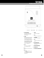
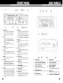
1
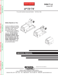
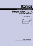
Visit HHB online at www.hhb.co.uk
HHB Communications Ltd · 73-75 Scrubs Lane, London NW10 6QU, UK
Tel: 020 8962 5000 · Fax: 020 8962 5050 · E-Mail: [email protected]
HHB Communications USA LLC · 1410 Centinela Avenue, Los Angeles, CA 90025-2501, USA
Tel: 310 319 1111 · Fax: 310 319 1311 · E-Mail: [email protected]
HHB Communications Canada Ltd · 260 King Street East, Toronto, Ontario M5A 4L5, Canada
Tel: 416 867 9000 · Fax: 416 867 1080 · E-Mail: [email protected]
HHB MDP500 PORTABLE MINIDISC RECORDER
SERVICE
MANUAL
CONTENTS
PORTADISC MDP500 MiniDisc Recorder
SAFETY INFORMATION
This service manual is intended for qualified service technicians; it is not meant for the casual do-it-yourselfer. Qualified
technicians have the necessary test equipment and tools, and have been trained to properly and safely repair complex
products such as those covered by this manual.
Improperly performed repairs can adversely affect the safety and reliability of the product and may void the warranty. If
you are not qualified to perform the repair of this product properly and safely, you should not risk trying to do so and
refer the repair to a qualified service technician.
This appliance is classified as a CLASS 1 LASER product, the CLASS 1 LASER product marking is on the rear of the
unit inside the battery compartment.
This equipment fully complies with 21 CFR 1040.10 and 1040.11
CAUTION: Invisible laser radiation when the unit is disassembled, avoid exposure to beam.
CONTENTS
1. DISASSEMBLY INSTRUCTIONS
. . . . . . . . 5-12
Removing The Top & Bottom Panels . . . . . . . . . . 5-6
Removing The Front Panel . . . . . . . . . . . . . . . . . 7-8
Removing The Main CPU Circuit Board . . . . . . . . . . 9
Removng The MD Mechanism . . . . . . . . . . . . . . 10
Removing The Analog Main & Sub Circuit Boards 11-12
2. BLOCK DIAGRAM . . . . . . . . . . . . . . . . . . . . 13
3. CIRCUIT DIAGRAMS . . . . . . . . . . . . . . . .
CPU . . . . . . . . . . . . . . . . . . . . . . . . . . . . . .
Power Supply CPU Board . . . . . . . . . . . . . . . .
Analog Inputs . . . . . . . . . . . . . . . . . . . . . . . .
Analog Output & Digital Coax I/O . . . . . . . . . . .
15-21
. . 15
. . 17
. . 19
. . 21
4. PCB LAYOUTS . . . . . . . . . . . . . . . . . . . .
CPU PCB Component Side . . . . . . . . . . . . . . .
CPU PCB Solder Side . . . . . . . . . . . . . . . . . . .
Analog Main Solder Side . . . . . . . . . . . . . . . .
Analog Main Component Side . . . . . . . . . . . . .
Analog Sub PCB Solder Side . . . . . . . . . . . . . .
Analog Sub PCB Component Side . . . . . . . . . .
Front Panel PCB Parts Side . . . . . . . . . . . . . .
Front Panel PCB Solder Side . . . . . . . . . . . . . .
Deck Panel PCB . . . . . . . . . . . . . . . . . . . . . .
24-33
. . 24
. . 25
. . 28
. . 29
. . 32
. . 33
. . 35
. . 35
. . 37
Focus Bias Adjustment . . . . . . . . . . . . . . . . . 45-46
Error Rate Confirmation . . . . . . . . . . . . . . . . . . . 46
Creating A Continuously Recorded Test Disc . . . . . 47
7. IC INFORMATION . . . . . . . . . . . . . . . . . . 49-50
8. PARTS LIST . . . . . . . . . . . . . . . . . . . . . .
Main Frame . . . . . . . . . . . . . . . . . . . . . . . .
CPU Unit . . . . . . . . . . . . . . . . . . . . . . . . . . .
Analog Main Unit . . . . . . . . . . . . . . . . . . . . .
Analog Sub Unit . . . . . . . . . . . . . . . . . . . . . .
51-53
51-52
. . 52
. . 53
. . 53
9. IDENTIFICATION OF PARTS . . . . . . . . . . . 55-58
Top Panel . . . . . . . . . . . . . . . . . . . . . . . . . . . . . 55
Front Panel . . . . . . . . . . . . . . . . . . . . . . . . . . . 56
Side Panels . . . . . . . . . . . . . . . . . . . . . . . . . . . 57
LCD Display . . . . . . . . . . . . . . . . . . . . . . . . . . . . 58
10. TECHNICAL DATA . . . . . . . . . . . . . . . . . . . 59
5. RESET INFORMATION . . . . . . . . . . . . . . . . . 39
6. TEST MODE & ALIGNMENT . . . . . . . . . .
Entering Test Mode . . . . . . . . . . . . . . . . . . . .
Switch Test Mode . . . . . . . . . . . . . . . . . . . . .
Mechanism Alignment Test Mode . . . . . . . . . .
Tools For Alignment . . . . . . . . . . . . . . . . . . . .
Button Operation During Alignment Test Mode .
The Alignment Modes . . . . . . . . . . . . . . . . . .
Test Mode Displays . . . . . . . . . . . . . . . . . . . .
Temperature Compensation Offset Adjustment .
Laser Power Adjustment . . . . . . . . . . . . . . . .
Traverse Adjustment . . . . . . . . . . . . . . . . . . .
2
41-47
. . 41
. . 41
. . 41
. . 42
. . 42
. . 42
. . 43
. . 43
. . 44
44-45
3
CONTENTS
PORTADISC MDP500 MiniDisc Recorder
SAFETY INFORMATION
This service manual is intended for qualified service technicians; it is not meant for the casual do-it-yourselfer. Qualified
technicians have the necessary test equipment and tools, and have been trained to properly and safely repair complex
products such as those covered by this manual.
Improperly performed repairs can adversely affect the safety and reliability of the product and may void the warranty. If
you are not qualified to perform the repair of this product properly and safely, you should not risk trying to do so and
refer the repair to a qualified service technician.
This appliance is classified as a CLASS 1 LASER product, the CLASS 1 LASER product marking is on the rear of the
unit inside the battery compartment.
This equipment fully complies with 21 CFR 1040.10 and 1040.11
CAUTION: Invisible laser radiation when the unit is disassembled, avoid exposure to beam.
CONTENTS
1. DISASSEMBLY INSTRUCTIONS
. . . . . . . . 5-12
Removing The Top & Bottom Panels . . . . . . . . . . 5-6
Removing The Front Panel . . . . . . . . . . . . . . . . . 7-8
Removing The Main CPU Circuit Board . . . . . . . . . . 9
Removng The MD Mechanism . . . . . . . . . . . . . . 10
Removing The Analog Main & Sub Circuit Boards 11-12
2. BLOCK DIAGRAM . . . . . . . . . . . . . . . . . . . . 13
3. CIRCUIT DIAGRAMS . . . . . . . . . . . . . . . .
CPU . . . . . . . . . . . . . . . . . . . . . . . . . . . . . .
Power Supply CPU Board . . . . . . . . . . . . . . . .
Analog Inputs . . . . . . . . . . . . . . . . . . . . . . . .
Analog Output & Digital Coax I/O . . . . . . . . . . .
15-21
. . 15
. . 17
. . 19
. . 21
4. PCB LAYOUTS . . . . . . . . . . . . . . . . . . . .
CPU PCB Component Side . . . . . . . . . . . . . . .
CPU PCB Solder Side . . . . . . . . . . . . . . . . . . .
Analog Main Solder Side . . . . . . . . . . . . . . . .
Analog Main Component Side . . . . . . . . . . . . .
Analog Sub PCB Solder Side . . . . . . . . . . . . . .
Analog Sub PCB Component Side . . . . . . . . . .
Front Panel PCB Parts Side . . . . . . . . . . . . . .
Front Panel PCB Solder Side . . . . . . . . . . . . . .
Deck Panel PCB . . . . . . . . . . . . . . . . . . . . . .
24-33
. . 24
. . 25
. . 28
. . 29
. . 32
. . 33
. . 35
. . 35
. . 37
Focus Bias Adjustment . . . . . . . . . . . . . . . . . 45-46
Error Rate Confirmation . . . . . . . . . . . . . . . . . . . 46
Creating A Continuously Recorded Test Disc . . . . . 47
7. IC INFORMATION . . . . . . . . . . . . . . . . . . 49-50
8. PARTS LIST . . . . . . . . . . . . . . . . . . . . . .
Main Frame . . . . . . . . . . . . . . . . . . . . . . . .
CPU Unit . . . . . . . . . . . . . . . . . . . . . . . . . . .
Analog Main Unit . . . . . . . . . . . . . . . . . . . . .
Analog Sub Unit . . . . . . . . . . . . . . . . . . . . . .
51-53
51-52
. . 52
. . 53
. . 53
9. IDENTIFICATION OF PARTS . . . . . . . . . . . 55-58
Top Panel . . . . . . . . . . . . . . . . . . . . . . . . . . . . . 55
Front Panel . . . . . . . . . . . . . . . . . . . . . . . . . . . 56
Side Panels . . . . . . . . . . . . . . . . . . . . . . . . . . . 57
LCD Display . . . . . . . . . . . . . . . . . . . . . . . . . . . . 58
10. TECHNICAL DATA . . . . . . . . . . . . . . . . . . . 59
5. RESET INFORMATION . . . . . . . . . . . . . . . . . 39
6. TEST MODE & ALIGNMENT . . . . . . . . . .
Entering Test Mode . . . . . . . . . . . . . . . . . . . .
Switch Test Mode . . . . . . . . . . . . . . . . . . . . .
Mechanism Alignment Test Mode . . . . . . . . . .
Tools For Alignment . . . . . . . . . . . . . . . . . . . .
Button Operation During Alignment Test Mode .
The Alignment Modes . . . . . . . . . . . . . . . . . .
Test Mode Displays . . . . . . . . . . . . . . . . . . . .
Temperature Compensation Offset Adjustment .
Laser Power Adjustment . . . . . . . . . . . . . . . .
Traverse Adjustment . . . . . . . . . . . . . . . . . . .
2
41-47
. . 41
. . 41
. . 41
. . 42
. . 42
. . 42
. . 43
. . 43
. . 44
44-45
3
DISASSEMBLY INSTRUCTIONS
PORTADISC MDP500 MiniDisc Recorder
Removing The Top And Bottom Panels
Instructions are best carried through in the following order:
a)
Slide off the plastic battery cover
b)
Remove the 4 screws (A) ~ fig.1
fig.1
c)
Remove the 2 screws (B) ~ fig.2
fig.2
4
5
DISASSEMBLY INSTRUCTIONS
PORTADISC MDP500 MiniDisc Recorder
Removing The Top And Bottom Panels
Instructions are best carried through in the following order:
a)
Slide off the plastic battery cover
b)
Remove the 4 screws (A) ~ fig.1
fig.1
c)
Remove the 2 screws (B) ~ fig.2
fig.2
4
5
DISASSEMBLY INSTRUCTIONS
DISASSEMBLY INSTRUCTIONS
PORTADISC MDP500 MiniDisc Recorder
PORTADISC MDP500 MiniDisc Recorder
Removing The Front Panel
d)
Remove the 2 screws (C) ~ fig.3
a)
Remove the dual concentric record level knob (A) by pushing through from behind the front panel ~ fig.5
b)
Remove the phone level knob (B)~ fig.5
fig.3
e)
Remove the top panel. Caution: Disconnect speaker connector (D) before fully separating the top panel
from the machine ~ fig.4
fig.5
c)
Remove 2 screws (C) ~ fig.6
fig.4
f)
6
Remove the bottom panel
fig.6
7
DISASSEMBLY INSTRUCTIONS
DISASSEMBLY INSTRUCTIONS
PORTADISC MDP500 MiniDisc Recorder
PORTADISC MDP500 MiniDisc Recorder
Removing The Main CPU Circuit Board
d)
Remove 2 screws (D) ~ fig.7
a)
Remove 4 screws (A) ~ fig.9
b)
Remove the SPDIF optical protector plugs if connected
c)
Lift up the CPU board carefully as the board is still attached by several cables
fig.9
fig.7
e)
Lift tab (F) ~ fig.6, then remove the front panel. Caution: Disconnect ribbon cable (1) before fully separating
the front panel from the machine ~ fig.8
d)
Disconnect 8 cables (1 - 8) and remove the board ~ fig.10
fig.8
fig.10
8
9
DISASSEMBLY INSTRUCTIONS
DISASSEMBLY INSTRUCTIONS
PORTADISC MDP500 MiniDisc Recorder
PORTADISC MDP500 MiniDisc Recorder
Removing The MD Mechanism
a)
Removing The Analog Main & Sub Circuit Boards
Remove 4 screws (A) ~ fig.11
a)
Remove 4 screws (A) ~ fig.12
fig.11
b)
Ensure cables (3) and (4) are disconnected ~ fig.10
c)
Lift out the MD mechanism
fig.12
10
b)
Disconnect the XLR input cables, (9) and (10) ~ fig.13
c)
Remove the Analog Sub pcb
d)
Remove 2 screws (B) to remove the metal shield plate ~ fig.12
e)
Remove the Record Level Pot locking nut and washer (C) ~ fig.13
f)
Disconnect cable, (11) ~ fig.13
g)
Remove 3 screws (D) ~ fig.13
11
DISASSEMBLY INSTRUCTIONS
DISASSEMBLY INSTRUCTIONS
PORTADISC MDP500 MiniDisc Recorder
PORTADISC MDP500 MiniDisc Recorder
Removing The MD Mechanism
a)
Removing The Analog Main & Sub Circuit Boards
Remove 4 screws (A) ~ fig.11
a)
Remove 4 screws (A) ~ fig.12
fig.11
b)
Ensure cables (3) and (4) are disconnected ~ fig.10
c)
Lift out the MD mechanism
fig.12
10
b)
Disconnect the XLR input cables, (9) and (10) ~ fig.13
c)
Remove the Analog Sub pcb
d)
Remove 2 screws (B) to remove the metal shield plate ~ fig.12
e)
Remove the Record Level Pot locking nut and washer (C) ~ fig.13
f)
Disconnect cable, (11) ~ fig.13
g)
Remove 3 screws (D) ~ fig.13
11
DISASSEMBLY INSTRUCTIONS
PORTADISC MDP500 MiniDisc Recorder
fig.13
h) Remove 5 screws (E) ~ fig.14
i)
Remove the connector side panel (F) ~ fig.14
j)
Lift out the Analog Main pcb.
fig.14
12
BLOCK DIAGRAM
PORTADISC MDP500 MiniDisc Recorder
13
CPU
PORTADISC MDP500 MiniDisc Recorder
15
POWER SUPPLY CPU BOARD
PORTADISC MDP500 MiniDisc Recorder
17
ANALOG INPUTS
PORTADISC MDP500 MiniDisc Recorder
19
ANALOG OUTPUT & DIGITAL COAX I/O
PORTADISC MDP500 MiniDisc Recorder
21
CPU PCB COMPONENT SIDE
PORTADISC MDP500 MiniDisc Recorder
24
CPU PCB SOLDER SIDE
PORTADISC MDP500 MiniDisc Recorder
25
ANALOG MAIN SOLDER SIDE
PORTADISC MDP500 MiniDisc Recorder
28
ANALOG MAIN COMPONENT SIDE
PORTADISC MDP500 MiniDisc Recorder
29
ANALOG SUB PCB SOLDER SIDE
PORTADISC MDP500 MiniDisc Recorder
32
ANALOG SUB PCB COMPONENT SIDE
PORTADISC MDP500 MiniDisc Recorder
33
FRONT PANEL PARTS & SOLDER SIDE
PORTADISC MDP500 MiniDisc Recorder
35
DECK PANEL PCB
PORTADISC MDP500 MiniDisc Recorder
37
RESET INFORMATION
PORTADISC MDP500 MiniDisc Recorder
There are 4 types of reset function which may be used to eliminate abnormal behaviour in the Portadisc. If having
implemented all the 4 reset types, and the MDP500 has not returned to normal behaviour, then investigate the
possibility of a fault or misalignment in the machine.
The four reset types are listed below:
1) F1 +F2 reset. Resets factory defaults
2) F1 +F3 reset. Resets factory defaults, user set-ups, clock
3) Power reset. Remove all power from machine. Remove external dc supply and batteries. Re-connect power and
power on.
4) System reset. Remove bottom panel. Locate and press SW1 on the main pcb.
38
39
TEST MODE & ALIGNMENT
PORTADISC MDP500 MiniDisc Recorder
Entering Test Mode
There are two test modes.
1) Switch Test Mode
2) Mechanism Alignment Test Mode
When ejecting a disc, always ensure that the disc has stopped rotating by pressing STOP. In addition, please be aware
that the record protection tab on a mini-disc is not detected in test mode, therefore it is possible to overwrite
recorded material.
Switch Test Mode
Hold down the F1 and Display buttons whilst simultaneously pressing the power switch. The Portadisc will appear to
have booted up in normal operation mode. Wait for about 5 seconds then press the Mark button. The MDP500 has
now entered 'SWITCH Test Mode'. This enables the engineer to check the operation of each of the switches on the
machine.
Each button has a unique test code as listed in the following table:
BUTTON
CODE
BUTTON
CODE
F1
K03
PAUSE
K02
F2
K09
KEYHOLD
K13
F3
K0B
OPEN
K10
LIGHT
K01
EDIT
K11
DISPLAY
K10
AMS BACK
K0F
INPUT
K12
AMS FFWD
K0E
MARK
K07
<<
K0C
SYSTEM
K05
PLAY
K0D
SETUP
K04
>>
K0A
RECORD
K08
STOP
K06
To exit from 'SWITCH Test Mode', press the POWER button until POWER DOWN appears in the display.
Mechanism Alignment Test Mode
Hold down the F1 and Display buttons whilst simultaneously pressing the power switch. The Portadisc will appear to
have booted up in normal operation mode. Wait for about 5 seconds then press the STOP button. Then press the
LIGHT button. TEMP ADJUST will be displayed.
Exit Alignment test mode by pressing SETUP then powering down.
Note: The above procedures should be followed exactly otherwise spurious display information may result.
40
41
TEST MODE & ALIGNMENT
TEST MODE & ALIGNMENT
PORTADISC MDP500 MiniDisc Recorder
Tools For Alignment
Oscilloscope; MD-LPM1 laser power meter; voltmeter; Sony test disc TDYS-1; Continuously recorded disc (see end
of this section for details on how to create one of these discs).
PORTADISC MDP500 MiniDisc Recorder
Test Mode Diisplays
The display button is used to toggle through the following display pages:
a)
Button Operation During Alignment Test Mode
Alignment Mode b) Error rate display c) Address display d) Auto gain display e) IVR display
The Auto gain and IVR displays are not used during servicing.
BUTTON
FUNCTION
1. Error Rate Display
AMS BACK
Cycles back through the various alignment pages and used to adjust parameter values
C1 = XXXX AD = XX
OPEN
Ejects the disc
C1 indicates the data error rate
AMS FFWD
Cycles FFWD through the various alignment pages and used to adjust parameter values
AD indicates the address error rate
PLAY
Spindle servo ON
2. Address display
>>
Used to manually traverse the sled assembly towards the outer diameter
h = header address; s = sub-code Q channel address; a = ADIP (address in pre-groove) address.
STOP
Stops rotation of the disc. This should always be pressed before ejecting the disc. Also turns
off laser.
If '----' is displayed, then the address can not be read.
<<
Used to manually traverse the sled assembly towards the inner diameter
The header address (h) is the unique address of each data block and is contained within the data itself.
DISPLAY
Toggles between the various test mode displays (see below)
F1
YES
F3
NO
The sub-code Q channel (s) contains the address information extracted from the sub-code data. This should be the
same as the header address.
The ADIP address (a) is the unique address pre-stamped on a recordable disc using modulated wobble.
3. Auto Gain Display
AG F=XX T=XX
The Alignment Modes
F indicates acquired Focus Auto Gain value
Select the alignment mode by using the AMS BACK and FFWD buttons. Enter the alignment mode by pressing F1. Exit
the alignment mode by pressing F3.
ALIGNMENT MODE
DESCRIPTION
TEMP ADJUST
Temperature compensation offset
LDPWR ADJUST
Laser Power adjustment
LDPWR CHECK
Laser Power check
EFBAL ADJUST
Traverse adjustment
FBIAS ADJUST
Focus Bias adjustment
FBIAS CHECK
Focus Bias check
CPLAY MODE
Continuous playback mode
CREC MODE
Continuous record mode
EEP MODE
Do not use
42
T indicates acquired Tracking Auto Gain value
Temperature Compensation Offset Adjustment
This adjustment saves the temperature data as a 25oC reference for the alignment process.
· It is not necessary to perform this alignment unless the laser assembly is replaced
· Perform this adjustment just after turn on in an ambient temperature of between 22 to 28oC.
a)
Use the AMS buttons to locate the TEMP ADJUST page, then press F1 to select.
b)
Ensure that TEMP = XX where XX falls within the range 'E0-EF', 'F0-FF', '00-0F', '10-1F', '20-2F'.
c)
Press F1 to SAVE (SAVE will briefly be displayed) or press F3 to exit without saving.
43
TEST MODE & ALIGNMENT
TEST MODE & ALIGNMENT
PORTADISC MDP500 MiniDisc Recorder
PORTADISC MDP500 MiniDisc Recorder
Laser Power Adjustment
This adjustment requires the use of a laser power meter. It is highly recommended that the SONY MD-LPM1 Mini-disc
Laser Power Meter (Part No. 9-948-310-40) is used for this adjustment as it allows for more accurate and reliable
adjustment. This meter is built in to a minidisc case so that the meter can be loaded using the MD loading
mechanism.
b)
Load a recordable 74 mini-disc into the machine and use the << or >> buttons to move the optical lens to about
the middle of the disc.
c)
Use the AMS buttons to locate the EFBAL ADJUST page, then press F1 to display 'EFBAL MO-R'.
a)
Insert the laser power meter. Use the << and >> buttons to position the laser so that it is approximately in the
middle of the photo sensor of the power meter.
d)
Press F1 again to turn on the laser, focus servo and spindle servo. 'EFB = XX MO-R' will be displayed. Use the
AMS buttons to adjust for minimum tracking offset so that A = B as shown in the picture below.
b)
Use the AMS buttons to locate the LDPWR ADJUST page, then press F1 to select. The display should show 'LD
0.9mW $XX'.
c)
Use the AMS buttons to adjust for a laser power of between 0.80 to 0.96mW. Press F1 to save.
d)
The display should now show 'LD 7.0mW $XX'. Use the AMS buttons to adjust for a laser power of between 6.8
to 7.2mW. Press F1 to save. Note: Do not perform the emission with 7mW for more than about 15 seconds
continuously.
e)
The display should now return to the LDPWR ADJUST page. Use the AMS buttons to locate the LDPWR CHECK
page. Press F1 to cycle through the various powers and check that the readings are correct. Press F3 to exit.
e)
Press F1 to save the adjustment setting. The display will then show 'EFBAL MO-P'.
f)
Press F1 again to turn on the laser, focus servo and spindle servo. 'EFB = XX MO-P' will be displayed. Use the
AMS buttons to adjust for minimum tracking offset so that A = B as shown in the picture above.
g)
Press F1 to save the adjustment setting. The display will then show 'EFBAL MO-W'.
Traverse Adjustment
a)
Connect 1 channel of an oscilloscope to TE (Tracking error) and VC (Voltage reference for servo).
h) Press F1 again to turn on the laser, focus servo and spindle servo. 'EFB = XX MO-W' will be displayed. Use the
AMS buttons to adjust for minimum tracking offset so that A = B as shown in the picture above. Caution: This
adjustment sets the tracking offset during the record process, therefore do not use any disc where you want to
preserve the data.
i)
Press F1 to save the adjustment setting. The display will then show 'EFBAL CD'.
j)
Load test disc TDYS-1 or a pre-mastered high quality disc (CD pits and lands).
k)
Press F1 again to turn on the laser, focus servo and spindle servo. 'EFB = XX CD' will be displayed. Use the AMS
buttons to adjust for minimum tracking offset so that A = B as shown in the picture above.
l)
Press F1 to save the adjustment setting. The display will then show 'EFBAL ADJUST'.
m) Eject the disc.
The location of the TE and VC test points are shown in the following diagram:
Focus Bias Adjustment
44
a)
Load a 'continuously recorded disc'. Refer to 'Creating a Continuously Recorded Disc' below.
b)
Use the AMS buttons to locate the CPLAY MODE page.
c)
Press F1 to display CPLAY MID. As soon as 'C1 = XXXXAD =XX' is displayed, press F3.
d)
Use the AMS buttons to locate the FBIAS ADJUST page.
e)
Press F1 to display 'XXXX/XX a=XX'. The first 4 digits indicate the C1 error rate, the next 2 digits indicate ADER
(address error rate) and the a=XX indicates the focus bias value.
f)
Use the forward AMS button to adjust for a focus bias value which produces an average C1 error rate of 220.
The C1 error rate will vary quite considerably.
g)
Press the F1 button to save and to display 'XXXX/XX b=XX'.
45
TEST MODE & ALIGNMENT
TEST MODE & ALIGNMENT
PORTADISC MDP500 MiniDisc Recorder
PORTADISC MDP500 MiniDisc Recorder
Laser Power Adjustment
This adjustment requires the use of a laser power meter. It is highly recommended that the SONY MD-LPM1 Mini-disc
Laser Power Meter (Part No. 9-948-310-40) is used for this adjustment as it allows for more accurate and reliable
adjustment. This meter is built in to a minidisc case so that the meter can be loaded using the MD loading
mechanism.
b)
Load a recordable 74 mini-disc into the machine and use the << or >> buttons to move the optical lens to about
the middle of the disc.
c)
Use the AMS buttons to locate the EFBAL ADJUST page, then press F1 to display 'EFBAL MO-R'.
a)
Insert the laser power meter. Use the << and >> buttons to position the laser so that it is approximately in the
middle of the photo sensor of the power meter.
d)
Press F1 again to turn on the laser, focus servo and spindle servo. 'EFB = XX MO-R' will be displayed. Use the
AMS buttons to adjust for minimum tracking offset so that A = B as shown in the picture below.
b)
Use the AMS buttons to locate the LDPWR ADJUST page, then press F1 to select. The display should show 'LD
0.9mW $XX'.
c)
Use the AMS buttons to adjust for a laser power of between 0.80 to 0.96mW. Press F1 to save.
d)
The display should now show 'LD 7.0mW $XX'. Use the AMS buttons to adjust for a laser power of between 6.8
to 7.2mW. Press F1 to save. Note: Do not perform the emission with 7mW for more than about 15 seconds
continuously.
e)
The display should now return to the LDPWR ADJUST page. Use the AMS buttons to locate the LDPWR CHECK
page. Press F1 to cycle through the various powers and check that the readings are correct. Press F3 to exit.
e)
Press F1 to save the adjustment setting. The display will then show 'EFBAL MO-P'.
f)
Press F1 again to turn on the laser, focus servo and spindle servo. 'EFB = XX MO-P' will be displayed. Use the
AMS buttons to adjust for minimum tracking offset so that A = B as shown in the picture above.
g)
Press F1 to save the adjustment setting. The display will then show 'EFBAL MO-W'.
Traverse Adjustment
a)
Connect 1 channel of an oscilloscope to TE (Tracking error) and VC (Voltage reference for servo).
h) Press F1 again to turn on the laser, focus servo and spindle servo. 'EFB = XX MO-W' will be displayed. Use the
AMS buttons to adjust for minimum tracking offset so that A = B as shown in the picture above. Caution: This
adjustment sets the tracking offset during the record process, therefore do not use any disc where you want to
preserve the data.
i)
Press F1 to save the adjustment setting. The display will then show 'EFBAL CD'.
j)
Load test disc TDYS-1 or a pre-mastered high quality disc (CD pits and lands).
k)
Press F1 again to turn on the laser, focus servo and spindle servo. 'EFB = XX CD' will be displayed. Use the AMS
buttons to adjust for minimum tracking offset so that A = B as shown in the picture above.
l)
Press F1 to save the adjustment setting. The display will then show 'EFBAL ADJUST'.
m) Eject the disc.
The location of the TE and VC test points are shown in the following diagram:
Focus Bias Adjustment
44
a)
Load a 'continuously recorded disc'. Refer to 'Creating a Continuously Recorded Disc' below.
b)
Use the AMS buttons to locate the CPLAY MODE page.
c)
Press F1 to display CPLAY MID. As soon as 'C1 = XXXXAD =XX' is displayed, press F3.
d)
Use the AMS buttons to locate the FBIAS ADJUST page.
e)
Press F1 to display 'XXXX/XX a=XX'. The first 4 digits indicate the C1 error rate, the next 2 digits indicate ADER
(address error rate) and the a=XX indicates the focus bias value.
f)
Use the forward AMS button to adjust for a focus bias value which produces an average C1 error rate of 220.
The C1 error rate will vary quite considerably.
g)
Press the F1 button to save and to display 'XXXX/XX b=XX'.
45
TEST MODE & ALIGNMENT
PORTADISC MDP500 MiniDisc Recorder
TEST MODE & ALIGNMENT
PORTADISC MDP500 MiniDisc Recorder
Creating A Continuously Recorded Test Disc
h) Use the backward AMS button to adjust for a focus bias value which produces an average C1 error rate of 220.
i)
Press the F1 button to save and to display 'XXXX/XX c=XX'.
j)
Check that the C1 error rate is less than 50 and ADER is less than 2.
k)
Press the F1 button to save and to display 'XX-XX-XX (XX)'. If the (XX) value is more than 20, then press F1. If the
(XX) value is less than 20, press F3 and repeat the adjustment from step (b).
A continuously recorded disc should only be created using a well-aligned machine. This disc is required for performing
focus and error rate checks and adjustments.
1. Insert a fresh blank disc.
2. Use the AMS buttons to locate the CREC MODE page.
The relationship between the C1 error rate and the focus bias values a, b and c are shown in the graph below.
3. Press F1 to display CREC MID. The display will show the starting address of '0300' and recording will commence
automatically.
4. After 5 minutes, press F3 to stop recording.
5. Press OPEN to eject the disc.
Error Rate Confirmation
1. CD (Pre-mastered) Error rate check
a)
Load test disc TDYS-1
b)
Use the AMS buttons to display the CPLAY MODE
c)
Press F1 to display CPLAY MID. The display will change to show the C1 error rate.
d)
C1 error rate should be below 20.
e)
Press F3 to stop.
2. MO Error rate check
a)
Load a continuously recorded disc.
b)
Use the AMS buttons to display the CPLAY MODE
c)
Press F1 to display CPLAY MID. The display will change to show the C1 and ADER error rates.
d)
C1 error rate should be below 50 and ADER below 2.
e)
Press F3 to stop.
46
47
TEST MODE & ALIGNMENT
PORTADISC MDP500 MiniDisc Recorder
TEST MODE & ALIGNMENT
PORTADISC MDP500 MiniDisc Recorder
Creating A Continuously Recorded Test Disc
h) Use the backward AMS button to adjust for a focus bias value which produces an average C1 error rate of 220.
i)
Press the F1 button to save and to display 'XXXX/XX c=XX'.
j)
Check that the C1 error rate is less than 50 and ADER is less than 2.
k)
Press the F1 button to save and to display 'XX-XX-XX (XX)'. If the (XX) value is more than 20, then press F1. If the
(XX) value is less than 20, press F3 and repeat the adjustment from step (b).
A continuously recorded disc should only be created using a well-aligned machine. This disc is required for performing
focus and error rate checks and adjustments.
1. Insert a fresh blank disc.
2. Use the AMS buttons to locate the CREC MODE page.
The relationship between the C1 error rate and the focus bias values a, b and c are shown in the graph below.
3. Press F1 to display CREC MID. The display will show the starting address of '0300' and recording will commence
automatically.
4. After 5 minutes, press F3 to stop recording.
5. Press OPEN to eject the disc.
Error Rate Confirmation
1. CD (Pre-mastered) Error rate check
a)
Load test disc TDYS-1
b)
Use the AMS buttons to display the CPLAY MODE
c)
Press F1 to display CPLAY MID. The display will change to show the C1 error rate.
d)
C1 error rate should be below 20.
e)
Press F3 to stop.
2. MO Error rate check
a)
Load a continuously recorded disc.
b)
Use the AMS buttons to display the CPLAY MODE
c)
Press F1 to display CPLAY MID. The display will change to show the C1 and ADER error rates.
d)
C1 error rate should be below 50 and ADER below 2.
e)
Press F3 to stop.
46
47
IC INFORMATION
PORTADISC MDP500 MiniDisc Recorder
AK4520A 20Bit ADC/DAC
74HC4052 Analogue Multiplexer/Demultiplexer
Function Table
CONTROL INPUT
B
A
0
0
1
1
COMMON OUTPUTS
X
Y
0
1
0
1
X0
X1
X2
X3
Y0
Y1
Y2
Y3
IH = Inhibit, When IH is low, outputs are ON.
48
49
IC INFORMATION
PORTADISC MDP500 MiniDisc Recorder
AK4520A 20Bit ADC/DAC
74HC4052 Analogue Multiplexer/Demultiplexer
Function Table
CONTROL INPUT
B
A
0
0
1
1
COMMON OUTPUTS
X
Y
0
1
0
1
X0
X1
X2
X3
Y0
Y1
Y2
Y3
IH = Inhibit, When IH is low, outputs are ON.
48
49
IC INFORMATION
PARTS LIST
PORTADISC MDP500 MiniDisc Recorder
74HC4066 CMOS Quad Bilateral Switch
BA3308F ALC
NJM2360
50
PORTADISC MDP500 MiniDisc Recorder
Main Frame
No.
Part Name
Part Code
No.
Part Name
Part Code
1/1
Front Panel (ABS)
40-031-01
1/44
Screw top / bott rear - black
4 off CS M2.6x6
1/2
Battery housing (ABS)
43-055-01
1/45
Screw battery case
4 off RH M3x6
1/3
Battery Cover (ABS)
43-056-02
1/46
Screw PCB & brackets
21 off RH M3x4
1/4
Connector panel (ABS)
44-015-02
1/47
Screw screen -ext jack
4 off RH M2.6x6
1/5
Knob,Headphone-Level
51-047-04
1/48
Screw front panel
4 off CS M2.6x4
1/6
Knob, Rec-Level[R]
51-048-14
1/49
Screw LCD PCB
4 off RH M2x6
1/7
Knob, Rec-Level[L]
51-049-14
1/50
AC Adapter 100-230 Volt
MDP500ACADA
1/8
Knob-Rec
51-050-14
1/51
Rechargeable Battery
MDP500B
1/9
Keytop-Pause
51-051-14
1/52
Battery caddy
MDP500BC
1/10
Keytop-Power
51-052-04
1/53
Soft case & strap
MDP500CASE
1/11
Keytop-S-(a) light,mark
51-053-04a
1/54
Instruction Manual
MDP500OPMAN
1/12
Keytop-S-(b) disp, syst
51-053-04b
1/55
MD Mechanism
KMK-260AAA
1/13
Keytop-S-(c) input, set
51-053-04c
1/56
Electro Capacitor, C0
ECOS1CP153BB
1/14
Keytop-F F1-F3
51-054-03
1/57
LCD Module
L2462B1J000
1/15
Keytop-Deck (play etc)
51-055-02
1/58
CN5 Conn
AXP416618
1/16
Knob-Lock
51-056-03
1/59
CN6 socket conn
AXM116215
1/17
LCD-Display window
55-011-04
1/60
XLR Connector
XLM-3-31-PCS
1/18
Cover-Top (ABS)
58-010-02a
1/61
Speaker
S36G04K-3
1/19
Cover-Top (silicon)
58-010-02b
1/62
CPU PCB UNIT complete
91-113-00
1/20
Cover-MD slot (ABS)
58-011-13
1/63
ANALOG MAIN PCB UNIT
91-114-00
1/21
Chassis, complete
41-016-11
1/64
ANALOG SUB PCB UNIT
91-115-00
1/22
Cover-Upper
43-053-02
1/65
FRONT KEY PCB UNIT
91-116-00
1/23
Cover-Bottom
43-054-22
1/66
TOP KEY PCB UNIT
91-117-00
1/24
Bracket-Deck
46-040-13
1/67
EXT DC PCB bare
01-129-04
1/25
Bracket-Analog sub pcb
46-041-03
1/68
DC INPUT JACK
LGP6531-0400
1/26
Bracket-Record VR
46-042-04
1/69
CN102 (2-pin conn)
53253-0210
1/27
Bracket-Deck PCB
46-044-03
1/70
PHONE LEVEL PCB bare
01-128-04
1/28
Bracket Lock (1)
46-045-04
1/71
Gang VR400 (monitor level)
RK097121T
1/29
Bracket Lock (2)
46-046-04
1/72
CN402 (6-pin conn)
53253-0610
1/30
Terminal (1) Battery +
59-079-03
1/73
FRONT KEY PCB bare
01-126-03
1/31
Terminal (2) Battery -
59-080-04
1/74
Slide Switch REC SW2
SSST010600
1/32
Screw mech retaining
59-083-04
1/75
Tact Switch 11 of
PT-007-C12B
1/33
O Ring P3 - mech
Dia 2.5mm
1/76
LED (red) record
TLR-226
1/34
Bushing - mech
C30NG79-1
1/77
LED (yellow) pause
TLY-226
1/35
Bracket-Speaker
46-043-04
1/78
LED (green) charge
TLG-226
1/36
Rubber Foot
TM182-816
1/79
Connector
52806-1610
1/37
Screw MD slot - selftap
2 off RH M3x6
1/80
TOP KEY PCB bare
01-127-04
1/38
Screw top cover - selftap
8 off RH M3x5
1/81
Tact Switch 9 off
PT-007-C12B
1/39
Screw batt term - selftap
2 off RH M3x5
1/82
CN9 (7-pin conn)
53253-0710
1/40
Screw front panel PCB -st
5 off RH M2.6x6
1/83
Cable CN401-2 phones level
08-044-04
1/41
Screw lock bracket - selftap
4 off CS M2x6
1/84
Cable CN8-9 CPU - Deck Key
08-046-04
1/42
Screw case top / bott - black
4 off CS M3x6
1/85
Cable CN102-103 Ext DC I/p
08-047-04
1/43
Screw XLR panel - black
5 off RH M2.6x8
1/86
Cable CN403-speaker
08-048-04
51
PARTS LIST
PARTS LIST
PORTADISC MDP500 MiniDisc Recorder
Main Frame (continued)
PORTADISC MDP500 MiniDisc Recorder
Analog Main Unit
Analog Sub Unit
Part Code
No.
Part Name
Part Code
No.
Part Name
CN12 (4-way conn)
Z-282-04FD
3/1
ANALOG MAIN PCB
01-124-03
4/1
ANALOG SUB PCB
01-125-04
CN101 - 104 (2-pin conn)
53253-0210
3/2
IC209, 210
NJM2068M
4/2
IC200
NJM2110M
3/3
IC211, 212
NJM2121M
4/3
IC201, 203, 216
NJM2122M
IC202, 204, 207, 208
TC74HC4052F
No.
Part Name
Part Code
No.
Part Name
1/87
Cable CN101-battery
08-049-04a
2/33
Part Code
1/88
CN104-C0 (capacitor)
08-049-04b
2/34
1/89
Cable CN200, 201-XLR
08-050-04
2/35
Slide charge switch (SW100)
SS324F-B12H6.5
Tact reset switch (SW1)
PT-007-C12B
3/4
IC213
BA3308F
4/4
3/5
IC214
TC74HC4094F
4/5
IC205, 206
TC74HC4094F
Q200, 201
2SA1163
1/90
Cable CN6-LCD
08-051-04
2/36
1/91
FFC Cable CN1 to mech
UL20624-19
2/37
Back up Battery
Ml2020/H1B
Crystal 22.5792MHz
HCM49S
3/6
IC215
NJM2122M
4/6
3/7
IC217
TC74HC4066F
4/7
Q202, 203
2SC4116Y
D200, 201
1SS272
1/92
FFC Cable CN2 to mech
UL20624-16
2/38
1/93
FFC Cable CN10 to CN11
UL20624-16
2/39
Crystal 48 MHz
HC-49/US
2/40
Crystal 32.768 MHz
FTS-26
3/8
IC218, 403
TC74HC4052F
4/8
2/41
X3 (12.228M) Resonator
12.2MTJOC4
3/9
IC400 (AD/DA)
AK4520A-VF
4/9
RL200, 201 Relay
ATQ219SA
2/42
Toroidal Coil, T100
TF0804S-201Y1R6
3/10
IC401
NJM4580ED
4/10
Condenser Mic.
KUB2823
Part Code
2/43
L9, L101, 102 470 uH
RCH875 471K
3/11
IC402
TC74HCU04F
4/11
CN200, 201 (Inputs)
5530-03A
L104 33uH
RCH875 330K
3/12
IC404
NJM3414M
4/12
CN202 (12-pin conn)
LPC-12T5M
3/13
IC405
NJM2073M
4/13
E Cap 50V 22u C205-6,212-5 IH-UTCXM220M
4/14
E Cap 50V 100u C207,208
CPU Unit
No.
Part Name
2/1
CPU board 4 layer
01-123-03
2/44
2/2
IC8 (microprocessor)
TMP90CM37F
2/45
L105, 107, L109 1mH
RCH875 102K
L106 100mH
RCH875 101K
3/14
Q204-208, 210
2SC4116Y
2SC4213B
2/3
IC1
UDA1325H
2/46
2/4
IC2
TC74HC00F
2/47
Chip Coil
L1, 4 47uH
LQH3C470K04
3/15
Q400-407
Chip Coil
L2 3.3uH
LQG21N3R3K
3/16
Q408
2SA1163
BLM21A601F
3/17
D202, 203
1SS272
2/5
IC3
TC74LVX4245FS
2/48
2/6
IC4
TC74HC153F
2/49
Chip EMIFIL L3, 5, 6, 7, 8
2/7
IC5
AT24C16N-10SI
2/50
Resistor metal oxide 20W 2W R101RS14AB3D
3/18
Audio Pin Jack Line OP
LPR6520
2/8
IC9
TC74HC373F
2/51
E Capacitor 6.3V 47u C14,24 0J-UTCXM470M
3/19
Audio Pin Jack Dig I/O
LPR6520
2/52
E Capacitor 16V 100u C39,41,
3/20
Headphone Jack
S-G4617 #3
49,100,108,110,115,117-9 1C-UTES101M
3/21
CN203 (12-way conn)
LPC-12FDS
E Capacitor 50V 47u C109,113 1H-UTES470M
3/22
CN204 (4-pin conn)
HKP-04M1
E Cap 6.3V 1000u C111,114 OJ-UTESM102M
3/23
CN400 (20-pin conn)
HKP20M1
2/9
IC10
NJU6355EM
2/10
IC11 (Optical RX)
TORX173
2/11
IC12 (Eeprom software)
M27C256B-12FI
2/53
2/12
IC13 (Optical TX)
TOTX173
2/54
2/13
IC14
TC7S14F
3/24
CN401 (6-pin conn)
53253-0610
2/14
IC100
S80760AN-JQ-T1
3/25
CN403 (2-pin conn)
53253-0210
2/15
IC101, 102
NJM2360M
3/26
Record Lvl Pot. VR200
RK0972220
2/16
IC103
MAX1627ESA
3/27
Toroidal Coil, T400
TF0804S-201
2/17
IC104
NJU7201U50
3/28
Chip EMIFIL, L400-406
BLM21A601F
2/18
IC105, 106
LM2940CT-5.0
3/29
Inductor, L407,408 470uH
RCH875 471K
2/19
IC118
NJU7201U32
3/30
E Cap 10V 220u C441-2
1A-UTCX221M
2/20
Q100, 102
2SJ525
3/31
E Cap 6.3V 10u C443,445
OJ-UTCXS100M
2/21
Q101
2SC4116Y
3/32
2/22
D1,2,3,4,102, 107
1SS272
2/23
D5, D7,D8
1SS383
2/24
D100,101,103-105,109
U1GWJ44
2/25
USB Socket
USB-212-T
2/26
Mini DIN Socket (remote)
TCS7588-01-201
2/27
IC Socket 28 way
AXS 102811K
2/28
CN1 (19-way conn)
52806-1910
2/29
CN2, CN10 (16-way conn)
52806-1610
2/30
CN6 (16-way conn)
AXL216801
2/31
CN7 (20-way conn)
Z-282-20FD
2/32
CN8 (7-pin conn)
53253-0710
52
1H-UTES101M
E Cap 6.3V 100u C267,268
411,412,415,420,450
OJ-UTCXM101M
53
PARTS LIST
PARTS LIST
PORTADISC MDP500 MiniDisc Recorder
Main Frame (continued)
PORTADISC MDP500 MiniDisc Recorder
Analog Main Unit
Analog Sub Unit
Part Code
No.
Part Name
Part Code
No.
Part Name
CN12 (4-way conn)
Z-282-04FD
3/1
ANALOG MAIN PCB
01-124-03
4/1
ANALOG SUB PCB
01-125-04
CN101 - 104 (2-pin conn)
53253-0210
3/2
IC209, 210
NJM2068M
4/2
IC200
NJM2110M
3/3
IC211, 212
NJM2121M
4/3
IC201, 203, 216
NJM2122M
IC202, 204, 207, 208
TC74HC4052F
No.
Part Name
Part Code
No.
Part Name
1/87
Cable CN101-battery
08-049-04a
2/33
Part Code
1/88
CN104-C0 (capacitor)
08-049-04b
2/34
1/89
Cable CN200, 201-XLR
08-050-04
2/35
Slide charge switch (SW100)
SS324F-B12H6.5
Tact reset switch (SW1)
PT-007-C12B
3/4
IC213
BA3308F
4/4
3/5
IC214
TC74HC4094F
4/5
IC205, 206
TC74HC4094F
Q200, 201
2SA1163
1/90
Cable CN6-LCD
08-051-04
2/36
1/91
FFC Cable CN1 to mech
UL20624-19
2/37
Back up Battery
Ml2020/H1B
Crystal 22.5792MHz
HCM49S
3/6
IC215
NJM2122M
4/6
3/7
IC217
TC74HC4066F
4/7
Q202, 203
2SC4116Y
D200, 201
1SS272
1/92
FFC Cable CN2 to mech
UL20624-16
2/38
1/93
FFC Cable CN10 to CN11
UL20624-16
2/39
Crystal 48 MHz
HC-49/US
2/40
Crystal 32.768 MHz
FTS-26
3/8
IC218, 403
TC74HC4052F
4/8
2/41
X3 (12.228M) Resonator
12.2MTJOC4
3/9
IC400 (AD/DA)
AK4520A-VF
4/9
RL200, 201 Relay
ATQ219SA
2/42
Toroidal Coil, T100
TF0804S-201Y1R6
3/10
IC401
NJM4580ED
4/10
Condenser Mic.
KUB2823
Part Code
2/43
L9, L101, 102 470 uH
RCH875 471K
3/11
IC402
TC74HCU04F
4/11
CN200, 201 (Inputs)
5530-03A
L104 33uH
RCH875 330K
3/12
IC404
NJM3414M
4/12
CN202 (12-pin conn)
LPC-12T5M
3/13
IC405
NJM2073M
4/13
E Cap 50V 22u C205-6,212-5 IH-UTCXM220M
4/14
E Cap 50V 100u C207,208
CPU Unit
No.
Part Name
2/1
CPU board 4 layer
01-123-03
2/44
2/2
IC8 (microprocessor)
TMP90CM37F
2/45
L105, 107, L109 1mH
RCH875 102K
L106 100mH
RCH875 101K
3/14
Q204-208, 210
2SC4116Y
2SC4213B
2/3
IC1
UDA1325H
2/46
2/4
IC2
TC74HC00F
2/47
Chip Coil
L1, 4 47uH
LQH3C470K04
3/15
Q400-407
Chip Coil
L2 3.3uH
LQG21N3R3K
3/16
Q408
2SA1163
BLM21A601F
3/17
D202, 203
1SS272
2/5
IC3
TC74LVX4245FS
2/48
2/6
IC4
TC74HC153F
2/49
Chip EMIFIL L3, 5, 6, 7, 8
2/7
IC5
AT24C16N-10SI
2/50
Resistor metal oxide 20W 2W R101RS14AB3D
3/18
Audio Pin Jack Line OP
LPR6520
2/8
IC9
TC74HC373F
2/51
E Capacitor 6.3V 47u C14,24 0J-UTCXM470M
3/19
Audio Pin Jack Dig I/O
LPR6520
2/52
E Capacitor 16V 100u C39,41,
3/20
Headphone Jack
S-G4617 #3
49,100,108,110,115,117-9 1C-UTES101M
3/21
CN203 (12-way conn)
LPC-12FDS
E Capacitor 50V 47u C109,113 1H-UTES470M
3/22
CN204 (4-pin conn)
HKP-04M1
E Cap 6.3V 1000u C111,114 OJ-UTESM102M
3/23
CN400 (20-pin conn)
HKP20M1
2/9
IC10
NJU6355EM
2/10
IC11 (Optical RX)
TORX173
2/11
IC12 (Eeprom software)
M27C256B-12FI
2/53
2/12
IC13 (Optical TX)
TOTX173
2/54
2/13
IC14
TC7S14F
3/24
CN401 (6-pin conn)
53253-0610
2/14
IC100
S80760AN-JQ-T1
3/25
CN403 (2-pin conn)
53253-0210
2/15
IC101, 102
NJM2360M
3/26
Record Lvl Pot. VR200
RK0972220
2/16
IC103
MAX1627ESA
3/27
Toroidal Coil, T400
TF0804S-201
2/17
IC104
NJU7201U50
3/28
Chip EMIFIL, L400-406
BLM21A601F
2/18
IC105, 106
LM2940CT-5.0
3/29
Inductor, L407,408 470uH
RCH875 471K
2/19
IC118
NJU7201U32
3/30
E Cap 10V 220u C441-2
1A-UTCX221M
2/20
Q100, 102
2SJ525
3/31
E Cap 6.3V 10u C443,445
OJ-UTCXS100M
2/21
Q101
2SC4116Y
3/32
2/22
D1,2,3,4,102, 107
1SS272
2/23
D5, D7,D8
1SS383
2/24
D100,101,103-105,109
U1GWJ44
2/25
USB Socket
USB-212-T
2/26
Mini DIN Socket (remote)
TCS7588-01-201
2/27
IC Socket 28 way
AXS 102811K
2/28
CN1 (19-way conn)
52806-1910
2/29
CN2, CN10 (16-way conn)
52806-1610
2/30
CN6 (16-way conn)
AXL216801
2/31
CN7 (20-way conn)
Z-282-20FD
2/32
CN8 (7-pin conn)
53253-0710
52
1H-UTES101M
E Cap 6.3V 100u C267,268
411,412,415,420,450
OJ-UTCXM101M
53
TOP PANEL
PORTADISC MDP500 MiniDisc Recorder
2
3
4
5
BATTERY COMPARTMENT
This cover slides off (from right to left in this
view) and underneath is the battery caddy,
holding 8 x AA batteries.
KEYHOLD
Use this button to avoid any accidental operation
during recording. Each time you press the button
for more than two seconds, the hold function
changes from ‘Key Hold ON’ to ‘Key Hold OFF’ and
vice versa. The following buttons can still operate
even when the keyhold function is on: KEY HOLD,
LIGHT, MARK, DISPLAY and POWER. The remote
control connection will not be affected by this
function; i.e., it is always enabled.
OPEN
Press this button to eject the MD disc. This
function is disabled during recording.
EDIT
Use this button to enter the different edit modes.
6
REWIND
Rewinds the track during playback.
7
PLAY
Use this button to start playing back the track.
8
FAST FORWARD
Fast forwards the track during playback.
9
STOP
Use this button to stop the playback or recording
operation.
10
RECORD VOLUME CONTROL
Dual concentric control for independent left and
right level adjustment.
11
INTERNAL MONO MICROPHONE
12
MONITOR SPEAKER
13
SHOULDER STRAP ATTACHMENT POINTS
AMS
Use the ❙
button to move back one or more
tracks and the
button to move forward one
or more tracks. These buttons are also used in
editing and naming.
▲
▲
1
❙
▲
▲
54
55
FRONT PANEL
SIDE PANELS
PORTADISC MDP500 MiniDisc Recorder
14
PHONE LEVEL
Adjusts the volume level for the headphones and
monitor speaker. The control will pop out if you
press it. The monitor speaker will not function
during recording or when the headphones are
connected.
15
INPUT
Changes the following input related settings:
• Input source: MIC, LINE, DIGITAL, INT MIC, OFF
• Options for MIC: MIC-Att, BASSCUT, LIMITER,
PHANTOM
• Options for LINE: LIMITER
• Options for DIGITAL: COAXIAL, OPTICAL, USB
input connections
16
17
DISPLAY
Changes the display menu through disc time, level
margin, time & date.
LIGHT
Illuminates the display back light for a few seconds.
Hold it down for more than two seconds in order
for it to be continuously lit. Press it again to switch
off the light.
18
MARK
Marks the track number manually during record
mode and play/pause mode.
19
SYSTEM
Changes the following system settings: REC MODE,
TRACK-INCREMENT, THRESHOLD LEVEL,
AUTO-START/CUT, AUTO-PAUSE, PRE-RECORD,
HEADPHONE MONITOR, OVERWRITE MODE,
REPEAT MODE, DIGITAL OUTPUT and AUTO POWER
DOWN.
20
56
SETUP
Changes the following setup options: OPEN SETUP,
SAVE SETUP, CLOCK/DATE SETUP, DATE FORMAT,
PEAK HOLD METER and DISPLAY CONTRAST. Use
this button to save and recall set-ups. OPEN SETUP
consists of five user set-ups, which can be used to
store all the menu settings on the recorder, and
three recording presets – MIC REC, LINE REC and
DIGI REC.
21
REC LEVEL
Adjusts the analog recording level manually for mic
and line inputs. This control does not affect the
signal level when the AGC function is set to ‘ON’.
The outer control adjusts the left hand channel and
the inner control adjusts the right hand channel. A
friction lock between the two controls allows them
to move together but also be adjusted individually.
22
RECORD
Slide this button to the right to enter record mode.
23
POWER
Press this button for one second to power ON and
press for more than one second then release to
power OFF. This button does not turn the power off
during recording and TOC operations.
24
F1, F2, F3
Selects the parameters according to the
corresponding set-up functions on the display above.
25
LCD DISPLAY
Shows level metering, disc information, timing
information and all the menu select and control
displays.
26
REC LEVEL LOCK
Mechanically locks the REC LEVEL knob position in
order to avoid accidental adjustment. Slide this
button up to lock.
27
28
29
30
PORTADISC MDP500 MiniDisc Recorder
31
36
REC INDICATOR
This LED will light up red in record mode and blink
in record pause mode.
PHONES SOCKET
1/4" jack socket for headphone connection.
USB CONNECTOR
USB interface port for a compatible computer.
32
37
OPTICAL I/O CONNECTORS
(TOSlink.) SPDIF digital optical connectors.
BAT CHG INDICATOR
This LED will light up green when charging the
NiMH rechargeable batteries.
LINE OUT LEFT AND RIGHT CONNECTORS
(Unbalanced RCA phono.) To send analog output
signals to other equipment.
38
BATTERY COMPARTMENT
33
COAXIAL I/O CONNECTORS
(Unbalanced RCA phono.) SPDIF digital coaxial
connectors.
39
DC INPUT CONNECTOR
To connect the standard accessory AC adaptor,
or an optional car adaptor. DC12-14V.
34
MIC/LINE CONNECTORS
(Balanced XLR.) To connect either MIC or LINE
inputs.
40
MINIDISC SLOT
A disc must be inserted into this slot with the
arrow on the disc casing facing into the recorder.
35
REMOTE CONNECTOR
Parallel remote control connector.
41
SHOULDER STRAP ATTACHMENT POINTS
PAUSE INDICATOR
This LED will light up yellow in pause mode.
PAUSE BUTTON
Use this button to pause the record or playback
operation. Pressing this button before pressing the
record button will put the recorder into record
pause mode, ready for recording.
57
LCD DISPLAY
TECHNICAL DATA
PORTADISC MDP500 MiniDisc Recorder
PORTADISC MDP500 MiniDisc Recorder
GENERAL
Unbalanced line output
Format . . . . . . . . . . . . . . . . . . . MiniDisc digital audio system
Connector type . . . . . . . . . . . . . . . . . . . . . . . . . RCA phono
Disc
Output level . . . . . . . . . . . . . . . . +8dBu @ 0dBFS into >10k
. . . . . . . . . . . . . . . . . . . . . . . . . . . . . . . . . . MiniDisc
Recording method . . . . . . . . Magnetic field variation overwrite
Reading method . . . . . . . . . . . . . . Non contact optical pickup
Headphone output
Laser . . . . . . . . . . . Semiconductor laser (wavelength 780nm)
Connector type . . . . . . . . . . . . . . . . . . . . . 1/4" stereo jack
Record/playback time
Impedance . . . . . . . . . . . . . . . . . . . . . . . . . . . . . . . . . 32
Stereo mode . . . . . . . . . . . . . . . . . . . . . . . 80 minutes max
Output power . . . . . . . . . . . . . . . . . . . . . . . . . . . . . 15mW
Mono mode . . . . . . . . . . . . . . . . . . . . . . . 160 minutes max
Rotation speed . . Approx 400-900rpm Constant Linear Velocity
Remote control . . . . . . . . . . . . . . . . . . . . . . . . . . . . Parallel
Sampling frequency . . . . . . . . . . . . . . . . . . . . . . . . 44.1kHz
Connector type . . . . . . . . . . . . . . . . . . . . . . . 8-pin mini DIN
(with internal SRC to cater for 32kHz and 48kHz source signals)
Coding . . . . . . . . . . . . . . . . . . . . . . . . . . . . ATRAC Ver 4.5
Digital connectors
Modulation system . . . . . . EFM (Eight to Fourteen Modulation)
Coaxial digital input . . . . . . . . . . . . . . . . . . . . . . . . . . SPDIF
Channels . . . . . . . . . . . . . . . . . . . . . . . . . . . . . . . . . . . . 2
Connector type . . . . . . . . . . . . . . . . . . . . . . . . . RCA phono
Power requirement . . . . . . . . . . . . . . . . . . . . . . 12-14V DC
Input impedance . . . . . . . . . . . . . . . . . . . . . . . . . . . . . 75
Power consumption . . . . Approx 4.5W record, 3.5W playback
Input level . . . . . . . . . . . . . . . . . . . . . . . . . . . . . . . 0.5V p-p
Weight with batteries . . . . . . . . . . . . . . . . . 2.0kg / 4lbs 7oz
42-3
44
LEVEL INDICATOR
The bar meter shows the audio level in playback
and record. (42) left hand channel (43) right
hand channel.
RECORD/PLAYBACK MODE INDICATOR
The icons indicate pause, play and record
modes.
45
46
DISPLAY MODE INDICATOR
Displays the track number, record/play time,
remaining time, total recorded time, level
margin, date and time.
BATTERY INDICATOR
Indicates the battery capacity remaining or
whether the unit is connected to an external
power source (DC IN).
Weight without batteries . . . . . . . . . . . . . 1.8kg / 3lbs 15oz
Optical digital input . . . . . . . . . . . . . . . . . . . . . . . . . . SPDIF
Dimensions (WxHxD) . . 225 x 57 x 180mm/10 x 2.2 x 7.1 ins
Connector type . . . . . . . . . . . . . . . . . . . . . . . . . . . . TOSlink
Internal speaker power . . . . . . . . . . . . . . . . . . . . . . 250mW
Coaxial digital output . . . . . . . . . . . . . . . . . . . . . . . . . SPDIF
AUDIO
Connector type . . . . . . . . . . . . . . . . . . . . . . . . . RCA phono
Frequency response . . . . . . . . . . . . . 10Hz to 20kHz, - 0.5dB
Output impedance . . . . . . . . . . . . . . . . . . . . . . . . . . . . 75
Wow & flutter . . . . . . . . . . . . . . . . . Below measurable limits
Output level . . . . . . . . . . . . . . . . . . . . . . . . . . . . . 0.5V p-p
Signal to noise ratio (playback) . > 89dB bandwidth 22Hz to 22kHz
Dynamic range (line input) . . . . . . . . . . . . . . . . . . . . > 96dB
Optical digital output . . . . . . . . . . . . . . . . . . . . . . . . . SPDIF
Microphone EIN . . . . . . . . . . . . . . . . . . > 122dB A-weighted
Connector type . . . . . . . . . . . . . . . . . . . . . . . . . . . . TOSlink
THD & N @ 1kHz ref 0dBFS . < 0.02% bandwidth 22Hz to 22kHz
USB (Ver 1) input / output
Connector . . . . . . . . . . . . . . . . . . . . . . . . . . . . . . . . . . . . . Type B
I/O CONNECTIONS
Interface . . . . . . . . . . . . . . . . . . . . . . Windows 98/2000, Mac OS
Analog connectors
Balanced mic/line input
ACCESSORIES
Connector type . . XLR 3: Pin 2 + Hot; pin 3 - Cold; Pin 1 Ground
The following accessories are included as standard . . . . . . . . . .
Mic input level for 0dBFS (level control at max) . . . . . . -52dBu
Soft case, carrying strap, battery caddy with 8 x NiMH
Line input level for 0dBFS (level control at max) . . . . . . . -2dBu
rechargeable batteries, spare battery caddy, AC adaptor/charger,
Phantom power (mic inputs) . . . . . . . . . . . . . . . . +48V, 7mA
HHB MD80 MiniDisc, operating instructions, quick reference guide
NOTE: The specifications and design of this product are subject
to change without notice, due to improvements.
US patents 4,790,016 and 4,914,701 and foreign equivalents
licensed from Dolby Laboratories Licensing Corportation.
Published by HHB Communications Ltd.
Copyright © 2001 HHB Communications Ltd.
All rights reserved.
58
59
Visit HHB online at www.hhb.co.uk
HHB Communications Ltd · 73-75 Scrubs Lane, London NW10 6QU, UK
Tel: 020 8962 5000 · Fax: 020 8962 5050 · E-Mail: [email protected]
HHB Communications USA LLC · 1410 Centinela Avenue, Los Angeles, CA 90025-2501, USA
Tel: 310 319 1111 · Fax: 310 319 1311 · E-Mail: [email protected]
HHB Communications Canada Ltd · 260 King Street East, Toronto, Ontario M5A 4L5, Canada
Tel: 416 867 9000 · Fax: 416 867 1080 · E-Mail: [email protected]
La versión en español del manual de operaciones la encontrará en la web de HHB – www.hhb.co.uk
La version Française de ce manuel d’utilisation est disponible sur le site web de HHB à www.hhb.co.uk
Eine deutsche Version dieser Bedienungsanleitung ist im Internet unter der Adresse www.hhb.co.uk erhältlich.
HHB MDP500 PORTABLE MINIDISC RECORDER
SERVICE
MANUAL