1
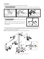
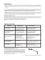
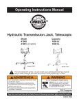
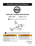
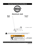
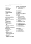
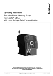
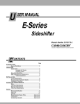
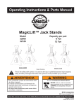
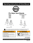
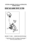
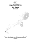
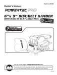
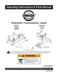
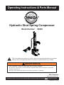
Operating Instructions & Parts Manual
Hydraulic Strut Spring Compressor
Model Number:
!
90000
This is the safety alert symbol. It is used to alert you to potential personal injury hazards.
Obey all safety messages that follow this symbol to avoid possible injury or death.
! ADVERTENCIA
• Leer, comprender, y seguir las instrucciónes antes de utilizar el aparato.
• El manual de instrucciónes y la información de seguridad deben estar comunicado en lengua del
operador antes del uso.
• No seguir estas indicaciónes puede causar daños personales o materiales.
SFA Companies
http://www.omegalift.com
Read this manual and follow all the Safety Rules and Operating Instructions before using this product.
Printed in China
90000-MR rev 12/07
SAFETY and GENERAL INFORMATION
Save these instructions. For your safety, read and understand the information contained within. The owner and
operator shall have an understanding of this product and safe operating procedures before attempting to use this
product. Instructions and Safety information shall be conveyed in the operators native language before use of this
product is authorized. Make certain that the operator thoroughly understands the inherent dangers associated with the
use and misuse of the product. If any doubt exists as to the safe and proper use of this product as outlined in this
factory authorized manual, remove from service.
Inspect before each use. Do not use if broken, bent, cracked or otherwise damaged parts are noted. Owners and
operators of this equipment shall be aware that the use and subsequent repair of this equipment may require special
training and knowledge. If this product appears to be damaged in any way, is worn or operates abnormally it shall be
removed from service immediately and the manufacturer notified. It is recommended that an annual inspection be done
by qualified personnel. Contact the manufacturer or distributor for a list of Authorized Service Centers. Labels and
Operator's Manuals are available from manufacturer.
PRODUCT DESCRIPTION
This Hydraulic Strut Spring Compressor is designed as an aid in replacing strut springs and strut assy components.
The adjustable strut shaft clasp secures the strut during operation. The spring clasp claws can be rotated to fit many,
but not all struts. Intended use: To compress springs for strut repair.
! Do not use for any purpose other than those uses outlined above!
SPECIFICATIONS
Model
Size
(LxW xH)
Hydraulic
Stroke
90000
12 1/4" x 11 7/8" x 52 5/8"
10"
Recommended Max. Working
Strut Spring Dia.
Space
4"
5" ~~ 10"
9"
15 1/2"
Wall Mounting Plate
Ram Bracket Channel
Upright
Ram
Spring Clasp Channel
Release Valve
Spring Clasp Claw
Hydraulic Pump
Strut Support
Handle
Strut Shaft Clasp
Oil Plug
Base
Base Mounting Plate
Figure 1 - Model 90000 Components
2
Operating
Force
102 lb.
ASSEMBLY
1. The product is preassembled except the upper and base mounting plates.
2 (a) For beam, bench & floor mount:
Attach Lower Wall Brackets (#14 & #16) to Upright (#13) using 4 Bolts (#15), 8 Washers (#20) and 4 Nuts (#26).
Connect
to wall
Connect to base
(1st & 3rd hole)
Left lower wall
bracket (#14)
Fig. 2 - Illustration for Beam Mount
Connect to base
(1st & 3rd hole)
Connect to base
(2nd & 3rd hole)
Left lower
wall bracket
(#14)
Left lower
wall bracket
(#14)
Connect to bench
Connect to floor
Fig. 3 - Illustration for Bench Mount
Fig. 4 - Illustration for Floor Mount
2 (b) For roll around legs option:
Attach each Leg (#35) to Upright (#13) using 4 Bolts (#38), 4 Nuts
(#39) and 8 Washers (#40).
Note: Do not attach lower wall brackets with roll around leg option.
Note: Wall mount is not for use on wooden studs, sheet rock or
similar materials.
Roll Around
Leg
Connect to
base
Fig. 5 - Illustration for Leg Support
3. Attach Upper Wall Bracket (#11) to top of Upright using 2 Bolts (#12). (optional for Bench and Floor mounting, and
not needed for leg support option). Note: Hardware needed to secure product to wall/ beam is not included.
4. Adjust strut support (#7) to fit the spring strut.
Note: Apply a light coating of bearing grease to mid-section of upright before using.
Figure 6 - Assembly Drawing for Model 90000
3
BEFORE USE
Note: Never service strut spring compressor while in use.
1. Verify that the product and the application are compatible, if in doubt call Omega Technical Service (888) 332-6419.
2. Before using this product, read the operator’s manual completely and familiarize yourself thoroughly with the
product, its components and recognize the potential hazards associated with its use.
2. Always refer to and have available a credible service manual covering the year, make and model of the vehicle
being serviced. Follow manufacturer's guidelines for strut removal, service and installation procedures.
3. Inspect before each use. DO NOT USE if bent, broken, cracked or leaking parts are noted. Repair or replace with
factory authorized components only.
! WARNING
• Study, understand, and follow all instructions
provided with and on this device before use.
• Ensure workpiece is compatible with and is
securely fastened in compressor fixture.
• Spring must be compressed sufficiently to remove
retaining nut and hardware.
• Never leave loaded spring compressor unattended.
• Use only on hard, level surfaces
• Do not use this device for any purpose other than
that for which it is intended.
• Do not modify this device.
• Failure to heed these markings may result in
personal injury and/or property damage.
! WARNING
Crush Hazard.
Keep hands and feet from
loading area.
! WARNING
Reduce risk of eye injury
by wearing safety goggles
when working with or
around this device.
OPERATION
Refer to the vehicle service manual, and follow the manufacturer's recommended procedure to remove the strut
assembly from the vehicle.
1. Secure the base of strut assembly to the compressor fixture by adjusting the strut shaft clasp (refer to Fig. 9).
2. Secure the spring with claws of spring clasp (refer Fig. 10).
3. Ensure that the strut assembly is set up vertically, and the spring is clasped centrally and evenly (refer to Fig. 7)
.
!
DO NOT use this strut spring compressor to compress springs which do not fully nest inside the
claws of the spring clasp assemblies. If a spring coil is only partially captured within the claw of a
clasp assembly, STOP, remove the strut spring assembly from the strut spring compressor. This means
that the application is not compatible to this type of product.
4. Close the pump release valve and start pumping to compress the spring.
5. After spring is compressed, install safety bar into the hole on upright directly above strut spring channel (refer
figure 8).
6. Ensure the spring is securely hooked on before removing the nut and retainer cup from the strut assembly.
7. Remove safety bar and decompress spring by opening the pump release valve slowly but no more than 2 full turns.
8. Remove/replace spring, components as needed.
9. Close the pump release valve and pump the handle to compress the new spring. Before compressing the spring,
ensure that the spring is securely hooked on the spring4clasp.
10. Install safety bar in upright directly above strut spring channel.
11. Install retainer cup assembly and nut.
12. Remove safety bar and decompress spring by opening the pump release valve.
13. Remove strut assembly from fixture.
Spring Clasp
Channel
Shock
Safety
Bar
Upright
Claws of
Spring
Clasp
Spring
Coil
Figure 8
Install safety bar in upright directly
above the strut spring channel.
Figure 7
Ensure that the strut assembly is set
up vertically, and the spring is clasped
centrally and evenly.
Claw
Assembly
Adjustable
strut shaft
clasp
Figure 9
Secure the base with strut shaft clasp.
Figure 10
Position strut spring upright to service upper
strut components.
5
MAINTENANCE
1. Lubrication of upright is required in normal service. Coat all exposed surfaces with a light machine oil. DO NOT allows
lubricant to contact claw assemblies nor strut springs. If so, clean and dry thoroughly before using in the spring
compressor.
2. For ram and pump, always use clean approved hydraulic fluid and change as recommended or sooner if the fluid
becomes contaminated. Keep hydraulic system as free of dirt as possible. Inspect hoses and connections daily.
Tighten connections as needed. Use pipe thread sealing compound when servicing connections.
Important: Use only a good grade hydraulic jack oil. Avoid mixing different types of fl uid and Never use brake fluid,
turbine oil, transmission fl uid, motor oil or glycerin. Improper fl uid can cause premature failure of the ram and the
potential for sudden and immediate loss of load. We recommend Mobil DTE 13M or equivalent.
To Add/Change Hydraulic Fluid
Depressurize and disconnect hydraulic hose from application. Remove oil plug on top of the reservoir. Pour used fluid
into a sealable container. With pump in its upright, horizontal position, use a small funnel to fill reservoir to within 1/4"
(6mm) of the opening. Wipe up any spilled fluid and reinstall the oil plug.
Note: Dispose of hydraulic fluid in accordance with local regulations.
TROUBLESHOOTING
Symptom
Possible Causes
Corrective Action
Ram will not extend, or respond
to pressurized fluid
• Release valve not closed
• Contact Service Center
• Ensure release valve closed
• Contact Service Center
Ram responds to pressurized
fluid, but system does not
maintain pressure
• Release valve not closed
• Dirt in pump's return check valve
• Hydraulic unit malfunction
• Ensure release valve closed
• Contact Service Center
• Contact Service Center
Ram will not return fluid to
pump
• Malfunctioning coupler
damaged application
• Reservoir overfilled
• Bent plunger/ ram damage
• Open release valve, depressurize
pump and hose, remove application
and replace coupler
• Drain fluid to proper level
• Replace ram
Ram will not fully extend
(cylinder or spreader)
• Fluid level low
• Open release valve, depressurize
pump and hose, remove application,
then add fluid to proper level
Poor performance
• Fluid level low
• Air trapped in system
• Ensure proper fluid level
• Vent the sytem (refer to figure 11)
To bleed air from system (refer to Fig 11)
Place pump at a higher elevation than the hose and ram. The objective
is to "float the air bubbles up hill and back to the reservoir where
they belong. Close valve and extend ram as fast as possible. Open
valve fully allowing oil and air to return to reservoir. Repeat this
procedure two or three times will do the trick. To vent the pump, just
open the oil plug to let air escape.
Figure 11 - Pump and ram illustration to bleed air
6
REPLACEMENT PARTS
Not all components of the product are replacement items, but are illustrated as a convenient reference of location
and position in the assembly sequence. When ordering parts, give Model number, serial number and description.
Call or write for current pricing: SFA Companies 10939 N. Pomona Ave. Kansas City, MO 64153, U.S.A.
Tel:(888)332-6419 Fax:(816)891-6599 E-Mail: [email protected] Omega Website: http://www.omegalift.com
Ref
1
2
3
4
5
6
7
8
9
10
11
12
13
14
15
16
17
18
19
20
21
Part#
H22-1-2000-100
434-0-1000-104
H22-3-8100-106
513-5-0020-101
518-4-0160-106
518-4-0100-209
H22-3-8600-106
649-1-0100-100
511-3-0104-109
H22-6-8605-104
H22-6-8608-100
653-1-0100-014
H22-3-8500-102
H22-3-8607-100
653-1-0127-500
H22-3-8606-108
649-1-0080-027
H22-3-8200-100
681-1-0127-010
511-3-0130-010
514-2-0018-103
Description
Qty
Ram piston
1
Hydraulic pump
1
Ram bracket
1
Spring clip
2
Safety Bar D15.8 x 96
1
Ram position pin D10 x 76 1
Strut support
1
Bolt M10x1.5x10L
1
Washer D20x10.4x1.2
1
Strut shaft clasp
1
Wall bracket - upper
1
Bolt M10x1.5x16L
2
Upright assy.
1
Wall bracket - lower left
1
Bolt 1/2"-12UNC x1 1/4"
4
Wall bracket - lower right 1
Bolt - M8x1.25Px15L
1
Strut spring
1
Spring
claspchannel
channel
Wing nut 1/2" - 12 UNC
4
Washer D24 x 13 x 2.5T
8
Spring D18 x 2 x 15
2
Ref
22
23
24
25
26
27
28
29
30
31
32
33
34
35
36
37
38
39
40
-
Part#
H22-3-8204-108
H22-3-8300-104
H22-6-8305-102
651-1-0127-010
661-2-0127-519
H22-3-1700-105
511-3-0162-031
H22-6-8609-102
603-3-0130-107
653-1-0160-205
653-2-0160-023
428-4-3100-102
90001
G36-3-3300-106
G36-3-5000-104
G36-3-5001-106
653-1-0127-308
661-2-0127-601
511-3-0130-101
90000-L0
90000-M0
Description
Qty
Spring clasp bracket
1
Spring clasp holder
2
Sping clasp / claw
2
Screw 1/2"-12 UNCx1/2"
2
Nut W1/2 x 12 UNC
4
Knob
1
Washer D31 x 16.2 x 4T
1
L Bracket
1
Washer D30 x 13 x 5T
6
Bolt - M16 xP2 x90L
4
Nut - M16 x P2
4
Hose assy.
1
Leg assy. (accessory) 1
Support leg
2
2
Caster
Caster with brake
2
Bolt
4
Nut - nylon
4
Washer
8
Label
1
Manual
1
Figure 12 - Replacement Parts Illustration for Model 90000
7
ONE YEAR LIMITED WARRANTY
For a period of one (1) year from date of purchase, SFA Companies will repair or replace, at its option, without
charge, any of its products which fails due to a defect in material or workmanship under normal usage. This limited
warranty is a consumer's exclusive remedy.
Performance of any obligation under this warranty may be obtained by returning the warranted product, freight
prepaid, to SFA Companies Warranty Service Department, 10939 N. Pomona Ave., Kansas City, MO 64153.
Except where such limitations and exclusions are specifically prohibited by applicable law, (1) THE CONSUMER'S SOLE AND EXCLUSIVE REMEDY SHALL BE THE REPAIR OR REPLACEMENT OF DEFECTIVE PRODUCTS
AS DESCRIBED ABOVE. (2) SFA Companies SHALL NOT BE LIABLE FOR ANY CONSEQUENTIAL OR INCIDENTAL DAMAGE OR LOSS WHATSOEVER. (3) ANY IMPLIED WARRANTIES, INCLUDING WITHOUT LIMITATION THE
IMPLIED WARRANTIES OF MERCHANTABILITY AND FITNESS FOR A PARTICULAR PURPOSE, SHALL BE LIMITED TO ONE YEAR, OTHERWISE THE REPAIR, REPLACEMENT OR REFUND AS PROVIDED UNDER THIS
EXPRESS LIMITED WARRANTY IS THE EXCLUSIVE REMEDY OF THE CONSUMER, AND IS PROVIDED IN LIEU
OF ALL OTHER WARRANTIES, EXPRESS OR IMPLIED. (4) ANY MODIFICATION, ALTERATION, ABUSE, UNAUTHORIZED SERVICE OR ORNAMENTAL DESIGN VOIDS THIS WARRANTY AND IS NOT COVERED BY THIS WARRANTY.
Some states do not allow limitations on how long an implied warranty lasts, so the above limitation may not
apply to you. Some states do not allow the exclusion or limitation of incidental or consequential damages, so the above
limitation or exclusion may not apply to you. This warranty gives you specific legal rights, and you may also have other
rights which vary from state to state.
SFA Companies
10939 N. Pomona Ave. Kansas City, MO 64153
888-332-6419
[email protected]
8