1
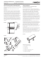
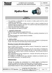
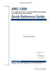
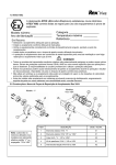
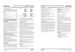
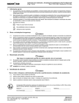
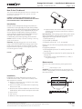
Orange Peel® Guards • Installation & Maintenance
Type LSG • Sizes 10 thru 70
(Page 1 of 3)
How To Use This Manual
This manual provides detailed instructions on installation and
maintenance of Orange Peel Guards, Type LSG, Line Shaft
Guards, Sizes 10 thru 70.
RO
TAT OR
IN AN
G GE
SH P
AF EEL
TG
UA
R
CAREFULLY FOLLOW THE INSTRUCTIONS IN THIS
MANUAL AND SUPPLEMENTAL POWER TOOL MANUALS
FOR OPTIMUM SAFETY AND PERFORMANCE.
DS
Introduction
NOTICE: Install and operate Orange Peel products in
conformance with applicable local and national safety
codes and per the supplied Orange Peel installation and
maintenance manual. It is the responsibility of the end
user to determine if ANSI safety warning, translated
warning labels or symbol based safety label training is
required in their facility to ensure complete
understanding of the warning being communicated.
Caution: Observe all safety rules when installing or servicing
guards and equipment.
WARNING: exposed Moving parts can cause severe
injury. LOCK OUT POWER at the starting switch of the
prime mover and remove all external loads from the
equipment before opening or removing the guard. Do
not use the guard as a step.
FIGURE 1
Optional 3mm/0.125 stainless steel pop rivets (8) and
installation tool (for mechanical attachment of optional
warning labels)
Lock Out Power at the starting switch of the prime mover.
l
Clean all installation surfaces. Remove parts from the
shipping box and verify quantities: (Figure 1)
1. Service manual (1)
2. Guard half (as ordered)
3. Optional end cap (0,1, or 2- as required)
Fastener kits can either be supplied by Rexnord or by the
customer.
IF supplied by Rexnord:
4. Hex head bolts (6mm for 10 and 20, 8mm for 30
through 70)
5. Hex head locknuts (6mm for 10 and 20, 8mm for 30
through 70)
l
END CAP
Foundation customer supplied fasteners (4- .500”); if
using optional leg kit.
Measurements
Determine and record the following trimming dimensions:
A: _________
C: _________If optional leg kit is used.
LSG 1/2 GUARD
SERVICE
MANUAL
HARDWARE
WARNING: Accurate measurements are required! It is the
installer’s responsibility to limit all interface gaps to less
than 6mm/0.250”.
Installation
A
Installation of Orange Peel Rotating Guards requires
standard mechanics tools, a power saw or handsaw, and a
drill. Examples are as follows:
l Band saw, reciprocating saw, or hand saw with a blade
suitable for cutting aluminum
l Electric or hand drill with suitable drill bit if optional leg
extensions are used.
l
6mm for sizes 10/20 and 8mm for sizes 30-70 hex
head sockets, socket wrench and open-end wrench
l
Torque wrench
Tape measure
Metal file or other appropriate de-burring tool
l
l
Prime
Mover
(RPM)
Rexnord Industries, LLC, Coupling Group
5555 South Moorland Road, New Berlin, WI 53151-7953 USA Telephone: 262-796-4060
Fax: 262-796-4064 e-mail: [email protected] web: www.rexnord.com
Driven
Equipment
D
C
Non-Rotating
Surface
Guard Mounting Surface
118-360
May 2006
NEW
Installation & Maintenance • Orange Peel Guards
Type LSG • Size 20 thru 70
(Page 2 of 3)
Guard Trimming and Pre-Assembly (FIG 2)
Guard Installation
Trim the aluminum guard section(s) to the A measurement. The
guard section flange holes are spaced at 25.4 mm (1.00 inch)
increments.
Foundation attachment, using optional Leg kit
Caution: Be sure to trim the guard sections to their
mating half.
These can be scribed or marked using the other extension
half, to help ensure a straight cut. Be sure to double
check your work. Support the section to be trimmed. It
should be held firmly for safe trimming following the
sawing tool manufactures operating instructions. Be sure
to read and follow the instructions thoroughly. After
trimming, file or de-burr the respective sections flat and
smooth. You can now bolt the optional end caps (if
required) to their mating guard section. The end cap
center tab can be permanently fastened to guard half by
drilling a pilot hole into the guard section and fasten
with a bolt to retain it in place (one fastener per guard
section).
25.4 mm
(1” TYPICAL)
FIGURE 2
DRILL & TAP
GUARD HALF
“A” TYPICAL
BOTH HALVES
CUT LINE
Refer to Figure 3 for parts list
Use the pre-determined centerline of the equipment
being guarded. Cut the u-channel to length required for
given centerline. For u-channel dimension, subtract the
radius of the LSG guard (See Table 1, Page 3) plus
0.500” (the thickness of the wing bracket and base
bracket) from the centerline dimension, cut u-channel
accordingly. Put the base bracket on to the u-channel
temporarily and the wing bracket on the u-channel
temporarily. Do a preliminary verification fit of the guard
and leg kit on the equipment, trim if necessary. At this
time determine where the legs will be positioned on both
the bottom of the guard and the base. You may have to
manually bend the wing bracket to form it to the radius
of the guard for proper fit. Mark the mounting holes for
the wing bracket at this time.
Remove guard from the machine and drill holes into
guard for mounting holes on the wing bracket. Install the
wing brackets to the guard; be sure to put the locknuts
on the guard outside to allow for proper clearances.
Drill or fasten studs to foundation. Attach the base
bracket to the U-channel and the U-channel to the wing
brackets. Position the guard into proper location and
re-verify the fit.
Position bottom guard section with leg kit(s) installed to guard
section in its final location. Be sure the rotating members are
centered in the guard and that no gaps greater than
6mm/0.250” exist. Mark the foundation drilling location in the
center of each leg base hole. Drill or tap a hole for use with a
suitable customer supplied fastener or mounting stud. See
Figure 4 for leg kit base layout.
OPTIONAL
END CAP
FIGURE 4
FIGURE 3
0.75
WING
FITTING
4.25
UN
IST
RU
T
4.25
6.00
35
.5
6.00
BOLT
3.50
NUT
LOCKWASHER
CHANNEL
NUT
0.25
118-360
May 2006
NEW
Optional Leg Kit parts list:
1. 1-35.5” length u-channel
2. 1-wing fitting
3. 1- square base
4. 4- channel nuts
5. 6- 0.500”-13 hex head cap screws
6. 2- 0.500”-13 Hexagon nuts
7. 2- 0.500” Lock washers
Rexnord Industries, LLC, Coupling Group
5555 South Moorland Road, New Berlin, WI 5315-7953 USA Telephone: 262-796-4060
Fax: 262-796-4064 e-mail: [email protected] web: www.rexnord.com
Orange Peel Guards • Installation & Maintenance
Type LSG • Sizes 10 thru 70
(Page 3 of 3)
Machine mounting of guard
All of the LSG guards can be mounted and supported
directly to machinery with customer supplied mounting
brackets and hardware. It is the customers’ responsibility
to ensure that the mounting brackets are of sufficient
strength and integrity. The LSG 10/20 have 6mm flange
bolt holes and the LSG 30-70 has 8mm flange bolt
holes spaced at 25mm (1.0 inch) increments.
Final Assembly
Bolt the bottom guard section to the foundation through
the leg kit or position bottom guard section on customer
supplied machine mounting brackets. (Leg kit brackets
should be assembled with the locknuts on the guard
outside to allow for proper clearances) in its final
location. Be sure the rotating members are centered in
the guard and that no gaps greater than 6mm/0.250”
exist. You can now bolt the optional end caps (if
required) to their mating guard section. The end cap
center tab can be drilled and bolted to retain it in place.
(1 fastener per guard section).
If Orange Peel leg kits are used, mount leg kits to base /
foundation using customer supplied .500” fasteners. See
Figure 4 for leg kit base layout.
Put the top guard section half on and mount all
fasteners. See Table 2 for proper tightening torque
values. Guard flange fasteners should be used at a
minimum of 2 foot intervals. Finally, tighten all guard
flange fasteners to required torque and tighten
foundation / machine fasteners as required.
Safety Labels
If a safety label is required, clean the area where it will
be installed and install the safety label. For severe wash
down or other environments requiring mechanical label
attachment, pop rivets can be utilized. Use 4,
3mm/0.125” medium length stainless steel pop rivets at
the label corners to provide mechanical attachment.
Available safety Labels
Part # 2924296
Start Up — prior to starting equipment, inspect the guard
installation for proper rotating equipment clearances.
Equipment Servicing
WARNING: LOCK OUT POWER at the starting switch of
the prime mover and remove all external loads from
equipment before opening or removing the guard.
To open the guard, remove the flange fasteners and any
machine mounting fasteners that utilize the flange holes.
Open the guard by removing the top half of the guard. If a
major repair is being made, completely remove the guard
from the foundation or machine and re-install BEFORE
equipment is unlocked and started.
Guard Maintenance
Orange Peel guards are relatively maintenance free. They
may need periodic painting and are supplied with
non-corrosive stainless steel hardware. Periodic visual
inspection should be performed every 60 days, along with
general equipment inspections with equipment shutdown
and locked out. Check the guard for any damage or
component failure. Check tightening torques on all
fasteners. Also, make sure that the safety labels are clean
and readable. If the safety label becomes loose, damaged,
or unreadable, contact the Factory or a sales representative
for replacement labels or guard service parts.
TABLE 1 — LSG Guard Radius
LSG Guard Size
Guard Radius (Inches)
10
20
30
40
50
60
70
1.500
2.500
3.500
4.625
5.625
6.375
8.375
TABLE 2 — Tightening Torques
Part # 2924290
Bolt
Size
Type
‡
‡
6 mm
8 mm
0.500” - 13
Stainless
Stainless
Galvanized
Tightening Torques
In-Lb
Nm
108
180
600
12
20
70
‡ Factory supplied fasteners.
Rexnord Industries, LLC, Coupling Group
5555 South Moorland Road, New Berlin, WI 53151-7953 USA Telephone: 262-796-4060
Fax: 262-796-4064 e-mail: [email protected] web: www.rexnord.com
118-360
May 2006
NEW