1
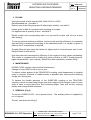
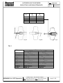
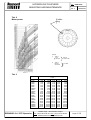
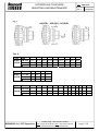
HYDROFLOW COUPLERS
MOUNTING AND MAINTENANCE
Réf:
89301e641
Ed : e
10/05/2004
ATEX
Shipped
WITHOUT OIL
·
·
·
·
The purchaser is responsible for the provision of safety guards and the correct
installation of all equipment.
During operation, the coupler contains hot oil, which in case of overload may be
ejected through the opening of the fuse. The customer should take precautions and
provide an adequate safety guard.
Read instructions before installing coupler.
Check alignment and fixation of coupler.
1. SHIPPING CONDITIONS
HYDRO-FLOW couplers are supplied without oil.
They are equipped with seals allowing a continuous operating temperature up to
90°C.
For higher temperatures, special seals are available.
Refer to REXNORD.
2. INSTALLATION
Guards and other safety devices must not prevent good ventilation of hydrodynamic
coupler. Also make sure that fusible plug remains accessible.
Mounting of coupler with hollow shaft (fig.1A)
Mount HYDRO-FLOW coupler onto shaft by means of threaded bar, screwed into
shaft, a piece of tube and a nut.
To prevent turning of shaft during mounting, use two nuts locked on threaded bar.
Remove bar from shaft and lock coupling with bolt. In case coupler is mounted on
motorshaft, use inertia of motor to remove mounting bar. This can also be done to
tighten said bolt.
If the motorshaft does’nt have a tapped hole , a hammer with soft top will help you to
slide coupler on it., see fig. 1B
For installation of HYDRO-FLOW types H(X)C(R), H(X)E(R) and H(X)P(R) refer to
gear coupling instructions. For spacing see fig.3.
Alignment (fig.3)
Although the coupling can compensate for a limited degree of misalignment,
excessive misalignment will lead to premature wear of the flexible sleeve..
Parallel alignment can be checked with a straight edge, angular alignment with feeler
gauge.Respect distance E. Max. permissible misalignments : see table 4.
REXNORD S.A / PTP Operation
La belle Orge – 88110 Raon L’Etape
Tel : (33) 3 29 52 62 72 / Fax : (33) 3 29 41 92 03
[email protected]
Page 1
/ 12
HYDROFLOW COUPLERS
MOUNTING AND MAINTENANCE
Réf:
89301e641
Ed : e
10/05/2004
3. FILLING
Use light mineral oil with viscosity ISO 3448 (VG15 or VG22).
Recommended oils : see table 1
Remove one of the filling plugs and fill with proper quantity : see table 2.
Letters given in table 2 correspond with markings on coupler.
For approximate oil quantity in litres : see table 3.
Rotate coupler until corresponding mark is on top and fill coupler until oil is on a level
with opening.
To ensure optimum working conditions, (minimum slip and high efficiency) it is essential
that the filling is determined according to the absorbed power. For values not given in
tables 2 and 3, interpolation is required.
A higher filling will give lower slip values but higher peak to nominal torque ratio. Lower
filling will have reverse effect.
High slip values will decrease the efficiency of the coupler and may cause overheating.
The coupler is equipped with a fusible plug which will blow at 140°C (fusible plugs for
higher temperatures : upon request). Should fuse blow repeatedly, increase filling.
4. MAINTENANCE
HYDRO-FLOW couplers require limited maintenance.
Change oil every 8000 hours or once a year.
To replace rubber bushes of the PENCOFLEX coupling, axial displacement of coupled
motor is required. Removal of rubber bushes is possible after removing the retaining
circlips from driving pins.
To replace the flexible elements of the SUREFLEX coupling or the TEXOFLEX
coupling, remove screws fitting flanges onto their support. Push flanges closer to each
other in order to move them from their centering spigot. Then, pull out the coupling
radially and change flexible elements .
5. REMOVAL (Fig.2)
To remove HYDRO-FLOW , use a special screw . This auxiliary device is supplied by
us on request.
Thread : see dimension M-fig.2.
REXNORD S.A / PTP Operation
La belle Orge – 88110 Raon L’Etape
Tel : (33) 3 29 52 62 72 / Fax : (33) 3 29 41 92 03
[email protected]
Page 2
/ 12
HYDROFLOW COUPLERS
MOUNTING AND MAINTENANCE
Size
M
H.(R)
M
HX.(R)
190
250-400
350-400
450-620
680-870
1/2‘‘-20 UNF
M20
R 1‘‘
R 1 1/4‘‘
M45
1/2‘‘-20 UNF
5/8‘‘-18 UNF
1 1/4‘‘-12 UNF
1 5/8‘‘-12 UNF
1 7/8‘‘-12 UNF
Fig.1A
Réf:
89301e641
Ed : e
10/05/2004
Fig.2
Fig.1B
Tab. 1
Oil viscosity
Oil brands
ARAL
BP
CHEVRON
ELF
ESSO
FINA
GULF
MOBIL OIL
SHELL
TEXACO
TOTAL
REXNORD S.A / PTP Operation
VG15
Vitam GF 10
Energol HLP 15
EP Hydraulic Oil 15
Spinelf 15
Nuto H 15
Hydran 10
Harmony 15AW
D.T.E 11
Tellus Oil R 10
Rando HDZ 15
Azolla 15
VG22
Vitam GF 22
Energol HLP 22
EP Hydraulic Oil 22
Olna 22
Teresso 32
Hydran 22
Harmony 22AW
Velocite 10
Tellus Oil S22
Spindura 22
Azolla 22
La belle Orge – 88110 Raon L’Etape
Tel : (33) 3 29 52 62 72 / Fax : (33) 3 29 41 92 03
[email protected]
Page 3
/ 12
HYDROFLOW COUPLERS
MOUNTING AND MAINTENANCE
Tab. 2
Motor power
Réf:
89301e641
Ed : e
10/05/2004
Fusible
plug
Example
1)
2)
Table 2 :
11 kW
@1.450 rpm
Table 3 :
Filling B
Size H.280
filling B
of size H.280
2,55 litres
Tab. 3
Size
H.190
H.250
H.280
H.320
H.350
H.R350
H.400
H.R400
H.450
H.R450
H.490
H.R490
H.540
H.R540
H.620
H.R620
H.R680
H.R750
H.R870
REXNORD S.A / PTP Operation
A
0.92
1.95
2.75
4.10
5.20
7.50
7.60
9.90
11.50
15.90
14.00
18.90
19.00
27.60
28.50
37.50
57.00
72.00
107.00
Oil quantity
Litres
B
C
0.80
0.86
1.70
1.80
2.35
2.55
3.50
3.80
4.40
4.80
6.30
7.00
6.60
7.10
8.90
9.50
11.00 10.00
14.40 13.60
13.50 12.50
17.80 15.90
18.00 16.50
25.40 23.50
26.50 24.50
34.50 31.50
53.00 50.00
68.50 63.00
100.00 92.50
D
0.73
1.55
2.10
3.20
4.00
5.70
6.00
7.70
9.00
12.90
11.00
15.10
15.50
21.90
22.50
28.80
46.50
59.00
88.50
E
0.65
1.40
1.85
2.90
3.60
5.10
5.40
6.30
8.00
11.70
10.00
14.00
13.50
19.70
20.50
26.10
43.00
54.00
83.50
La belle Orge – 88110 Raon L’Etape
Tel : (33) 3 29 52 62 72 / Fax : (33) 3 29 41 92 03
[email protected]
Page 4
/ 12
HYDROFLOW COUPLERS
MOUNTING AND MAINTENANCE
Fig. 3
Réf:
89301e641
Ed : e
10/05/2004
H(X)E(R) – H(X)C(R) – H(X)P(R)
Tab. 4
Size
DE
E mm
H(X)ER (b-a) mm
Dr mm
Type
H(X)E
250
280
320
33+2
40+2
40+2
2,4
2,8
2,8
3,3
0,5
0,6
0,6
0,6
620
Size
DE
E mm 9+2
H(X)CR (b-a) mm 2,2
1,0
Dr mm
Type
H(X)C
Size
DE
E mm
H(X)PR (b-a) mm
Dr mm
Type
H(X)P
190
350
750
870
9+2
11+2
11+2
2,4
2,8
2,8
1,0
1,2
1,2
280
450
490
540
620
64+3
73+3
88+3
88+3
3,8
4,5
5,0
6,2
6,2
0,8
0,8
1,0
1,2
1,2
350
400
46+2,5 53+2,5
680
250
400
320
450 490 540 620 680 750
3,5+1,5 3,5+1,5 3,5+1,5 3,5+1,5 3,5+1,5 3,5+1,5 4+2 4+2 4+2
870
4+2 4+2 4+2 5,5+2,5
0,30
0,30
0,30
0,30
0,30
0,30
0,45 0,45 0,45 0,45 0,45 0,45
0,60
0,2
0,2
0,2
0,2
0,2
0,2
0,3
0,3
REXNORD S.A / PTP Operation
0,3
0,3
La belle Orge – 88110 Raon L’Etape
Tel : (33) 3 29 52 62 72 / Fax : (33) 3 29 41 92 03
[email protected]
0,3 0,3 0,3
Page 5
/ 12
HYDROFLOW COUPLERS
MOUNTING AND MAINTENANCE
Réf:
89301e641
Ed : e
10/05/2004
Record each misalignment value., calculate the ratio of this value by the maximum
indicated value.
The sum of these ratios shall not exceed 1 :
dr/Dr+ da/Da + dE/DE <1
with :
dr : recorded radial misalignment value
Dr : max. radial masalignment value
da: recorded angular misalignment value
Da: max. angular masalignment value
dE : recorded axial misalignment value
DE : max. axial masalignment value
Verification measurements shall be made at four points located 90° apart
Make alignment without the flexible elements .
Checking for correct alignment is best done after the equipment is warmed up .
REXNORD S.A / PTP Operation
La belle Orge – 88110 Raon L’Etape
Tel : (33) 3 29 52 62 72 / Fax : (33) 3 29 41 92 03
[email protected]
Page 6
/ 12
HYDROFLOW COUPLERS
MOUNTING AND MAINTENANCE
Réf:
89301e641
Ed : e
10/05/2004
6. GROUNDED
The coupling or the shafts it is mounted on should be electrically grounded.
REXNORD S.A / PTP Operation
La belle Orge – 88110 Raon L’Etape
Tel : (33) 3 29 52 62 72 / Fax : (33) 3 29 41 92 03
[email protected]
Page 7
/ 12
HYDROFLOW COUPLERS
MOUNTING AND MAINTENANCE
Réf:
89301e641
Ed : e
10/05/2004
7. USE IN EXPLOSIVE AREA.
Indications and instructions concerning the use in explosive areas :
7-1-Control intervals for use in explosive areas.
Explosion group
II 2D c
Controls intervals
The visual check of the coupler must be effected after 100 operating
hours for the first time, after one month at the latest.
If no leaks are observed the further inspections must be effected
every 2000 operating hours or every 3 months at the latest.
In case of leakage a search of the possible causes must be effected
in accordance with the chapter «dysfunction and remedies »
The periodicity of checks has to be reseted in case of change of
operating conditions.
7-2-Wear measurement.
Refer to the service manual of the coupling.
!
CAUTION : To insure a long lifetime of the coupling and to avoid dangers
regarding in explosive areas the misalignment must be carefully checked.
7-3-Couplers materials.
Housing material : Aluminium alloy G Al Si 9 according to UNI 3051 (EN AB43100).
Shaft and covers material : Steel.
7-4-Marking of couplers for explosive areas.
Couplers for the use in hazardous areas are marked :
II 2 D
The surface temperature has to be noticed with order. Standard value by omission
145°C.
7-5-Start-up.
Before the start-up check the tightening of the setscrews or the tightening of the screw
on shaft end.
Check the alignment and the distance between the coupling plate or the belt tension.
In case of use, check the tightening of the fixation nuts of the thermal protection
detector and the speed controller. Check the speed controller setting too.
In explosive ambience the screws must be protected against self-loosening for
example by use of bond on threading.
REXNORD S.A / PTP Operation
La belle Orge – 88110 Raon L’Etape
Tel : (33) 3 29 52 62 72 / Fax : (33) 3 29 41 92 03
[email protected]
Page 8
/ 12
HYDROFLOW COUPLERS
MOUNTING AND MAINTENANCE
Réf:
89301e641
Ed : e
10/05/2004
7-6- dysfunction and remedies .
For the versions with coupling: Refer to the service manual of the coupling.
Dysfunction
Cause
Danger in explosive
Solution
areas
Misalignment.
Wear of
Danger of oil leakage.
coupling elastic
elements.
Noises and/or
vibrations in operation
self-loosening
Danger of
of the axial
inflammation due to
fixation of the sparking.
coupler.
Belt slip (HV and HVR
versions)
Belts wear.
Belts tension
insufficient.
REXNORD S.A / PTP Operation
Danger of
inflammation due to
sparking.
1) put the unit out of
operation.
2) Eliminate the cause of
misalignment (loose
foundation bolt, break of
machine fixing, heat
expansion, mounting
dimensions non respected,
deflection on load.
3) Check the wear of
coupling elastic elements
and change it if necessary.
4) Check the oil level of the
coupler and fill in if
necessary.
5) Check the alignment
stationary and in operation
and correct it if necessary.
1) put the unit out of
operation.
2) Dismantle the axial
fixation and remove the
coupler.
3) Check the coupler parts
and change it if necessary.
4) reassemble the coupler
on the shaft.
5) Check the alignment
stationary and in operation
and correct it if necessary.
1) put the unit out of
operation.
2) Establish the cause of the
slip.
3) Replace the belts.
4) Check the belts tension
after some hours of
operation. Correct it if
necessary.
La belle Orge – 88110 Raon L’Etape
Tel : (33) 3 29 52 62 72 / Fax : (33) 3 29 41 92 03
[email protected]
Page 9
/ 12
HYDROFLOW COUPLERS
MOUNTING AND MAINTENANCE
Réf:
89301e641
Ed : e
10/05/2004
7-6- dysfunction and remedies (suite).
Dysfunction
Danger
areas
Cause
in
explosive
The operating
conditions are
not in
accordance with
the coupler
performance.
Activation of thermal
protection or fusible
plug fusion.
Mistake at the
machine start.
Danger of superheated
oil leakage.
Machine lock.
Contact with
aggressive
liquids
hydrocarbon,
ozone…
Oil leakage on
coupler.
Misalignment.
Solution
1) put the unit out of operation.
2) Check the operating conditions
and select a bigger coupler.
3) Install the new coupler.
4) Check the alignment stationary
and in operation and correct it if
necessary.
1) put the unit out of operation.
2) check the coupling elastic
elements or the belts. Change it if
necessary.
3) Fill the coupler with the requested
oil quantity.
4) Check the alignment stationary
and in operation and correct it if
necessary.
5) Train and drill the working and
maintenance staff.
1) put the unit out of operation.
2) Detect and eliminate the cause of
machine lock.
3) Replace the fusible plug or reset
the thermal protection.
4) Fill the coupler with the requested
oil quantity.
5) Check the alignment stationary
and in operation and correct it if
necessary.
1) put the unit out of operation.
2) Detect and plug the leak.
3) Fill the coupler with the requested
oil quantity.
4) Protect the coupler from any
contact with the faulty fluid.
1) put the unit out of operation.
2) Eliminate the cause of
misalignment.
3) Detect and plug the leak.
4) Fill the coupler with the requested
oil quantity.
5) Check the alignment stationary
and in operation and correct it if
necessary.
CAUTION !: REXNORD does not assume any liabilities or guarantees regarding the
use of spare parts and accessories not provided by REXNORD and for the damages
resulting here from.
REXNORD S.A / PTP Operation
La belle Orge – 88110 Raon L’Etape
Tel : (33) 3 29 52 62 72 / Fax : (33) 3 29 41 92 03
[email protected]
Page 10
/ 12
HYDROFLOW COUPLERS
MOUNTING AND MAINTENANCE
Réf:
89301e641
Ed : e
10/05/2004
SPARE PARTS
COUPLERS WITHOUT DELAY CHAMBER
H(X)C-H(X)E-HXF- H(X)O-H(X)P-HXS-H(X)V
TYPE
Size
POS.
H(X)C
H(X)E
HXF
H(X)V
H(X)O
H(X)P
HXS
190
250
280
320
350
400
450
490
540
620
4
X
X
U76-6198300 U76-6248300 U76-0280300 U76-6323400 U76-6355353 U76-6405533 U76-6456533 U76-6507533 U76-6558533 U76-6633533
5
X
X
086-6400001 086-6400021 086-6400021 U76-6088353 086-6400051 086-6400061 U76-6136353 U76-6136353 U76-6198300 U76-6198300
6
X
X
086-6400011 086-6400031 086-6400031 086-6400041 U76-6165262 U76-6190270 U76-6216262 U76-6216262 U76-6248300 U76-6248300
15
X
X
BA 20x35x7
BA 50x65x8
BA 50x65x8
16
X
X
6204 C3
6206 C3
6206 C3
6206 C3
6210 C3
6211 C3
6212 C3
6212 C3
6216 C3
6216 C3
BA
65x80x8
BA
45x60x8
BA
72x90x10
BASL
65x90x10
BA
72x90x10
BASL
65x90x10
BA
72x90x10
BASL
65x90x10
BA
92x120x12
BASL
80x100x10
BA
105x130x12
BA
105x130x12
BA
130x160x12
BASL
120x150x15
BA
130x160x12
BASL
120x150x15
BA
140X170x13
BA
130X160x12
BA
140X170x13
BA
130X160x12
16011 C3
16013 C3
16013 C3
16013 C3
16017 C3
16019 C3
16024 C3
16024 C3
6026 C3
6026 C3
16009 C3
6013 C3
6013 C3
6013 C3
6216 C3
6021 C3
6024 C3
6024 C3
6026 C3
6026 C3
20
X
X
21
X
X
30
52
X
X
H(X)E
29
H(X)P
BA 54x85x10 BA 54x85x10 BA 78x100x10 BA 78x100x10
086-6410001 086-6410001 086-6410001 086-6410001 086-6420001 086-6420001 086-6420001 086-6420001 086-6420001
BA
65x80x8
X
BA 30x50x10 BA 30x50x10 BA 30x50x10
086-6420001
BASL
65x90x10
BASL
65x90x10
BASL
65x90x10
BASL
85x110x12
BA
105x130x12
BASL
120x150x15
BASL
120x150x15
BA
130x160x12
BA
130x160x12
350G1K003
350G1L003
350G1L003
350G1M003
350G1N003
350G1P003
350G1Q003
350G1R003
350G1R003
3x
3x
3x
6x
8x
8x
6x
6x
8x
034-0003101 034-0003101 034-0003101 034-0003101 034-0003101 034-0003101 034-0003201 034-0003201 034-0003201
8x
034-0003201
29 FLEXIBLE ELEMENT
OIL SEAL 52
H(X)C
30
H(X)E
FUSIBLE
PLUG
21 BEARING
BEARING 16
20 OIL SEAL
OIL SEAL 15
FLEXIBLE
29
ELEMENT
RUBBER
29
BUSHING
H(X)P
HO
HV
HXO
HXV
SEAL 5
O-RING 4
6
SEAL
SEAL 6
BEARING 21
OIL SEAL 20
REXNORD S.A / PTP Operation
La belle Orge – 88110 Raon L’Etape
Tel : (33) 3 29 52 62 72 / Fax : (33) 3 29 41 92 03
[email protected]
Page 11
/ 12
HYDROFLOW COUPLERS
MOUNTING AND MAINTENANCE
Réf:
89301e641
Ed : e
10/05/2004
SPARE PARTS
COUPLERS WITH DELAY CHAMBER
H(X)CR-H(X)ER-HXFR-H(X)OR-H(X)PR-HXSR-H(X)VR
TYPE
Size
POS.
H(X)CR
H(X)ER
HXFR
H(X)VR
H(X)PR
H(X)OR
HXSR
4
X
350
400
450
490
540
620
U766633
533
X
U76-6355353 U76-6405533 U76-6456533 U76-6507533 U76-6558533
U76-6165262 U76-6190270 U76-6216262 U76-6216262 U76-6248300 U76-6248300
6
X
X
15
X
X
BA 50x65x8
BA 50x65x8
16
X
X
6210 C3
6211 C3
6212 C3
6212 C3
6216 C3
6216 C3
BA
92x120x12
BASL
80x100x10
BA
105x130x12
BA
105x130x12
BA
130x160x12
BASL
120x150x15
BA
130x160x12
BASL
120x150x15
BA
140X170x13
BA
130X160x12
BA
140X170x13
BA
130X160x12
16017 C3
16019 C3
16024 C3
16024 C3
6026 C3
6026 C3
6216 C3
6021 C3
6024 C3
6024 C3
6026 C3
6026 C3
20
X
X
21
X
X
30
X
X
42
X
52
X
X
TF C103187
TF C103190
TF N6806BO
6218 C3
6220 C3
6224 C3
TF N6806BS
TF N6806BP
TF N6806BV
6034 C3
6038M C3
6044M C3
086-6420001
BASL
120x150x15
BASL
120x150x15
BA
130x160x12
H(X)ER
350G1M003
350G1R003
350G1R003
H(X)PR
8x
8x
6x
6x
8x
034-0003101 034-0003101 034-0003201 034-0003201 034-0003201
8x
034-0003201
350G1P003
350G1Q003
086-6450001
086-6450001
086-6450001
TF N6702CG
TF N6702CC
TF N6702DC
TF N6702CD
TF N6702CD
TF N6702CD
8x
352G2P001
8x
352G2Q001
8x
352G2Q001
BA
130x160x12
8x
352G2N001
350G1N003
TF C102251
TF C102254
H(X)CR
29
TF C102397
TF N6806BO
U76-6222353 U76-16252QQ U76-6323400 U76-6323400 U76-6392500 U76-6392500
BA
105x130x12
870
TF C102399
086-6420001 086-6420001 086-6420001 086-6420001 086-6420001
BASL
85x110x12
750
BA 54x85x10 BA 54x85x10 BA 78x100x10 BA 78x100x10 TF N6806BR
X
45
680
29 FLEXIBLE ELEMENT
H(X)CR
OIL SEAL 52
30 FUSIBLE PLUG
21 BEARING
O-RING 45
20 OIL SEAL
BEARING 16
H(X)ER
42 O-RING
OIL SEAL 15
FLEXIBLE ELEMENT 29
HOR
HOR
680
750
870
HVR
HXOR
RUBBER BUSHING 29
HXVR
20 OIL SEAL
6 SEAL
H(X)PR
6 SEAL
O-RING 4
SEAL 6
BEARING 21
OIL SEAL 20
REXNORD S.A / PTP Operation
La belle Orge – 88110 Raon L’Etape
Tel : (33) 3 29 52 62 72 / Fax : (33) 3 29 41 92 03
[email protected]
Page 12
/ 12