1
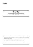
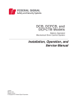
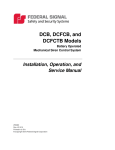
Models 2001-130, Equinox, and
508-128 Sirens
Installation, Operation, and
Service Manual
25500289
Rev. A0 1015
Printed in U.S.A.
© Copyright 2015 Federal Signal Corporation
Limited Warranty
The Alerting and Notification Systems Division of Federal Signal Corporation (Federal) warrants
each new product to be free from defects in material and workmanship, under normal use and
service, for a period of two years on parts replacement and factory-performed labor (one year
for Informer, EAS, and Federal software products) from the date of delivery to the first user-purchaser. Federal warrants every 2001-130, Equinox, Eclipse8 and 508-128 Siren (Top of pole
only) to be free from defects in material, per our standard warranty, under normal use and service for a period of five years on parts replacement.
During this warranty period, the obligation of Federal is limited to repairing or replacing, as Federal may elect, any part or parts of such product which after examination by Federal, are determined to be defective in material and/or workmanship.
Federal will provide warranty for any unit, which is delivered, transported prepaid, to the Federal
factory or designated authorized warranty service center for examination and such examination
reveals a defect in material and/or workmanship.
This warranty does not cover travel expenses, the cost of specialized equipment for gaining access to the product, or labor charges for removal and re-installation of the product. The Federal
Signal Corporation warranty shall not apply to components or accessories that have a separate
warranty by the original manufacturer, such as, but not limited to batteries.
Federal will provide on-site warranty service during the first 60-days after the completion of the
installation, when Federal has provided a turn-key installation including optimization and/or commissioning services.
This warranty does not extend to any unit which has been subjected to abuse, misuse, improper
installation or which has been inadequately maintained, nor to units which have problems related to service or modification at any facility other than the Federal factory or authorized warranty
service centers. Moreover, Federal shall have no liability with respect to defects arising in Products through any cause other than ordinary use (such as, for example, accident, fire, lightning,
water damage, or other remaining acts of God).
THERE ARE NO OTHER WARRANTIES, EXPRESSED OR IMPLIED, INCLUDING BUT NOT
LIMITED TO, ANY IMPLIED WARRANTIES OF MERCHANTABILITY OR FITNESS FOR A
PARTICULAR PURPOSE. IN NO EVENT SHALL FEDERAL BE LIABLE FOR ANY LOSS OF
PROFITS OR ANY INDIRECT OR CONSEQUENTIAL DAMAGES ARISING OUT OF ANY
SUCH DEFECT IN MATERIAL WORKMANSHIP.
2645 Federal Signal Drive, University Park, IL 60484-3167
Phone: 708-534-3400
Website: http://www.alertnotification.net
Contents
Safety Messages..................................................................................................................................... 6
General Description................................................................................................................................ 9
Introduction . ....................................................................................................................................... 9
Sirens Description............................................................................................................................... 9
Signal Description................................................................................................................................ 9
Specifications for Model 2001-130....................................................................................................... 10
Specifications for Equinox....................................................................................................................11
Specifications for Model 508-128......................................................................................................... 12
Installation Instructions........................................................................................................................ 13
Determining a Suitable Location........................................................................................................ 13
Installing the Sirens........................................................................................................................... 14
Pole Installation.......................................................................................................................... 14
Flat Surface Mount..................................................................................................................... 17
Wiring the Siren................................................................................................................................. 18
Pre-operation Checkout..................................................................................................................... 18
Service and Maintenance..................................................................................................................... 19
Testing and Inspecting the Siren....................................................................................................... 19
Servicing the Siren............................................................................................................................ 20
Adjusting the Clutch and Alarm Verification............................................................................... 21
Replacing the Blue Plug Over Collector Access Hole................................................................ 23
Replacing the Collector Ring and Brush Holder Assemblies..................................................... 24
Removing the Collector Ring Assembly..................................................................................... 25
Replacing the Rotator Motor...................................................................................................... 27
Replacing the Chopper Motor for the Models 2001-130 and Equinox Sirens............................ 27
Replacing the Chopper Motor for the Model 508-128 Siren....................................................... 27
Replacement Parts for Siren Head.................................................................................................... 28
Obtaining Service.................................................................................................................................. 28
Figures
Figure 1 Models 2001-130 and 508-128 Sirens..................................................................................... 9
Figure 2 Signal Characteristics............................................................................................................ 10
Installation, Operation, and Service Manual
3
Figure 3 Typical Pole Installation (Model 508-128 shown)................................................................ 15
Figure 4 Siren Leg Assembly............................................................................................................... 16
Figure 5 Leg Assembly Diameters....................................................................................................... 17
Figure 6 Mounting Plate Dimensions.................................................................................................. 17
Figure 7 Wiring for rotator motor......................................................................................................... 18
Figure 8 Rotator Assembly Interior .................................................................................................... 21
Figure 9 Spring Scale Attachment to Siren......................................................................................... 22
Figure 10 Aluminum tape...................................................................................................................... 23
Figure 11 Placing aluminum tape on access hole.............................................................................. 23
Figure 12 Collector Ring Housing........................................................................................................ 24
Figure 13 Installation/Removal Brush Assembly............................................................................... 24
Figure 14 Brush Holder Assembly....................................................................................................... 25
Figure 15 Collector Housing Opening................................................................................................. 26
Figure 16 Collector Rings..................................................................................................................... 26
Tables
Table 1 Power Requirements*.............................................................................................................. 10
Table 2 Wiring........................................................................................................................................ 10
Table 3 Motor Type................................................................................................................................ 10
Table 4 Signal Information.................................................................................................................... 10
Table 5 Dimensions............................................................................................................................... 10
Table 6 Weight........................................................................................................................................11
Table 7 Environmental...........................................................................................................................11
Table 8 Power Requirements*...............................................................................................................11
Table 9 Wiring.........................................................................................................................................11
Table 10 Motor Type...............................................................................................................................11
Table 11 Signal Information...................................................................................................................11
Table 12 Dimensions..............................................................................................................................11
Table 13 Weight......................................................................................................................................11
4
Models 2001-130, Equinox, and 508-128 Sirens

Table 14 Environmental.........................................................................................................................11
Table 15 Power Requirements*............................................................................................................ 12
Table 16 Wiring...................................................................................................................................... 12
Table 17 Motor Type.............................................................................................................................. 12
Table 18 Signal Information.................................................................................................................. 12
Table 19 Dimensions............................................................................................................................. 12
Table 20 Weight..................................................................................................................................... 12
Table 21 Environmental........................................................................................................................ 12
Table 22 Sound levels predictions....................................................................................................... 13
Table 23 Pre-operation checklist.......................................................................................................... 19
Table 24 Replacement Parts for Siren Head....................................................................................... 28
Installation, Operation, and Service Manual
5
Safety Messages
Safety Messages
It is important to follow all instructions shipped with this product. This device
is to be installed by trained personnel who are thoroughly familiar with the
country electric codes and will follow these guidelines as well as local codes.
Listed below are important safety instructions and precautions you should follow.
Important Notice
Federal Signal reserves the right to make changes to devices and specifications detailed in
the manual at any time in order to improve reliability, function or design. The information
in this manual has been carefully checked and is believed to be accurate; however, no
responsibility is assumed for any inaccuracies.
Publications
Federal Signal recommends the following publications from the Federal Emergency
Management Agency for assistance with planning an outdoor warning system:
•
The “Outdoor Warning Guide” (CPG 1-17)
•
“Civil Preparedness, Principles of Warning” (CPG 1-14)
•
FEMA-REP-1, Appendix 3 (Nuclear Plant Guideline)
•
FEMA-REP-10 (Nuclear Plant Guideline).
Planning
• If suitable warning equipment is not selected, the installation site for the siren
is not selected properly or the siren is not installed properly, it may not produce
the intended optimum audible warning. Follow Federal Emergency Management
Agency (FEMA) recommendations.
6
•
If sirens are not activated in a timely manner when an emergency condition
exists, they cannot provide the intended audible warning. It is imperative that
knowledgeable people, who are provided with the necessary information, are
available at all times to authorize the activation of the sirens.
•
When sirens are used out of doors, people indoors may not be able to hear the
warning signals. Separate warning devices or procedures may be needed to
effectively warn people indoors.
•
The sound output of sirens is capable of causing permanent hearing damage. To
prevent excessive exposure, carefully plan siren placement, post warnings, and
restrict access to areas near sirens.
•
Activating the sirens may not result in people taking the desired actions if those to
be warned are not properly trained about the meaning of siren sounds. Siren users
should follow FEMA recommendations and instruct those to be warned of correct
actions to be taken.
Models 2001-130, Equinox, and 508-128 Sirens
Safety Messages
•
After installation, service, or maintenance, test the siren system to confirm
that it is operating properly. Test the system regularly to confirm that it will be
operational in an emergency.
•
If future service and operating personnel do not have these instructions to refer
to, the siren system may not provide the intended audible warning and service
personnel may be exposed to death, permanent hearing loss, or other bodily
injury. File these instructions in a safe place and refer to them periodically. Give a
copy of these instructions to new recruits and trainees. Also give a copy to anyone
who is going to service or repair the siren.
Installation and Service
• Electrocution or severe personal injury can occur when performing various
installation and service functions such as making electrical connections, drilling
holes, or lifting equipment. Therefore only experienced electricians should install
this product in accordance with national, state and any other electrical codes
having jurisdiction. Perform all work under the direction of the installation or
service crew safety foreman.
•
The sound output of sirens is capable of causing permanent hearing damage.
To prevent excessive exposure, carefully plan siren placement, post warnings
and restrict access to areas near the sirens. Sirens may be operated from remote
control points. Whenever possible, disconnect all siren power including batteries
before working near the siren.
•
After installation or service, test the siren system to confirm that it is operating
properly. Test the system regularly to confirm that it will be operational in an
emergency.
•
If future service personnel do not have these warnings and all other instructions
shipped with the equipment to refer to, the siren system may not provide the
intended audible warning and service personnel may be exposed to death,
permanent hearing loss, or other bodily injury. File these instructions in a safe
place and refer to them periodically. Give a copy of these instructions to new
recruits and trainees. Also, give a copy to anyone who is going to service or repair
the sirens.
Operation
Failure to understand the capabilities and limitations of your siren system could result in
permanent hearing loss, other serious injuries or death to persons too close to the sirens
when you activate them or to those you need to warn. Carefully read and thoroughly
understand all safety notices in this manual and all operations-related-items in all
instruction manuals shipped with equipment. Thoroughly discuss all contingency plans
with those responsible for warning people in your community, company, or jurisdiction.
Installation, Operation, and Service Manual
7
Safety Messages
Read and understand the information contained in this manual before
attempting to install or service the siren.
Pay careful attention to the following notice located on the equipment.
8
Models 2001-130, Equinox, and 508-128 Sirens
General Description
General Description
Introduction
This manual describes the features, specifications, installation, service and maintenance
of the Models 2001-130, Equinox, and 508-128 Sirens.
Models 2001-130, Equinox, and 508-128 Sirens are electro-mechanical, dc, rotating
sirens that are capable of producing high intensity warning signals over a large area.
A highly efficient design enables the siren to produce a high sound level, while
making moderate demands on the power source. The Equinox Siren is identical to the
Model 2001-130 Siren except the stator is 8 ports instead of 12 ports.
Figure 1 Models 2001-130 and 508-128 Sirens
Sirens Description
Models 2001-130, Equinox, and 508-128 Sirens are single tone sirens capable of
producing a 130 dB, 125 dB, and 128 dB sound level respectively at 100 feet for a
minimum of 15 minutes, when using the DCB series Control Cabinet and Battery
Cabinet with fully charged, standard, deep-cycle, marine batteries. Up to thirty minutes
continuous operating time is available with the 2001TRBP option. This option supplies
dc current directly to the siren from a 208/220/240 Vac, optionally 480 Vac line.
The sirens use two motors. One to create the siren signals, the other one to rotate the
siren assembly. The first motor, which produces the sound energy, is attached to a stator
with a rotor mounted on the motor shaft concentric to the stator. The rotor and stator each
contain one row of ports. As the motor rotates the rotor, air is drawn into the rotor and
passes through the rotor and stator ports in pulses. These pulses are produced when the
rotor alternately opens and closes the stator ports. The pulses of air produce sound at a
frequency (pitch) that is dependent upon the rotational speed of the motor and the number
of ports in the rotor-stator combination.
Signal Description
The sirens are capable of producing a steady single frequency signal, a wailing rising
and falling frequency signal and a fast wailing signal. The steady signal is frequently
used as a civil defense “Alert” or weather emergency signal. The wailing signal is often
Installation, Operation, and Service Manual
9
Specifications for Model 2001-130
used as a civil defense “Attack” signal. The fast wail or fire signal is used as a fire signal
to summon the local fire department. You can use any of the signals for any desired
application. These signals are shown graphically in the following figure.
Figure 2 Signal Characteristics
STEADY SIGNAL "ALERT"
WAILING SIGNAL "ATTACK"
AUX1 SIGNAL "FIRE"
291A134A
Specifications for Model 2001-130
Table 1 Power Requirements*
Siren Motor
48 V (dc or full wave rectified ac) 100 amps (nom.)
Rotator Motor
48 V (dc or full wave rectified ac) 1 amp (nom.)
Table 2 Wiring
Siren Motor
2 AWG minimum, 2 wires
Rotator Motor
14 AWG minimum, 1 wire
Table 3 Motor Type
Siren
Series Wound dc 6.5 Hp (nom.)
Rotator
Permanent Magnet dc 1/8 Hp
Table 4 Signal Information
Signal
Frequency Range
Sweep Rate
WAIL
470 to 790 Hz
10 seconds
STEADY
790 Hz
FAST WAIL
Signal Duration
Sound Output (SPL)
Rotation
600 to 790 Hz
3 min. (programmable)
130 dBc +/-1 dBc (on axis) at 100 ft (30.5 m)
3 RPM
Table 5 Dimensions
Height x Width x Depth
10
62 in x 37 in x 41 in
1574 mm x 940 mm x 1041 mm
Models 2001-130, Equinox, and 508-128 Sirens
N.A.
3.6 seconds
Specifications for Equinox
Table 6 Weight
Shipping Weight
490 pounds (204 kg)
Siren Weight
420 pounds (190 kg)
Table 7 Environmental
Operating Temperature
-30°C to +60ºC**
* Power requirements refer to the power supplied by the batteries or optional ac operation
with battery backup.
** The siren can operate throughout this temperature range provided the battery
temperature is maintained at -18ºC or higher.
Specifications for Equinox
Table 8 Power Requirements*
Siren Motor
48 V (dc or full wave rectified ac) 115 amps (nom.)
Rotator Motor
48 V (dc or full wave rectified ac) 1 amp (nom.)
Table 9 Wiring
Siren Motor
2 AWG minimum, 2 wires
Rotator Motor
14 AWG minimum, 1 wire
Table 10 Motor Type
Siren
Series Wound dc 6.5 Hp (nom.)
Rotator
Permanent Magnet dc 1/8 Hp
Table 11 Signal Information
Signal
Frequency Range
Sweep Rate
WAIL
180 to 500 Hz
10 seconds
STEADY
500 Hz
FAST WAIL
Signal Duration
Sound Output (SPL)
Rotation
300 to 500 Hz
3 min. (programmable)
N.A.
3.6 seconds
125 dBc +/-1 dBc (on axis) at 100 ft (30.5 m)
3 RPM
Table 12 Dimensions
Height x Width x Depth
62 in x 37 in x 41 in
1574 mm x 940 mm x 1041 mm
Table 13 Weight
Shipping Weight
Siren Weight
460 pounds (209 kg) w/mtg. legs
390 pounds (159 kg)
Table 14 Environmental
Operating Temperature
-30°C to +60ºC**
* Power requirements refer to the power supplied by the batteries or optional ac operation
with battery backup.
Installation, Operation, and Service Manual
11
Specifications for Model 508-128
** The siren can operate throughout this temperature range provided the battery
temperature is maintained at -18ºC or higher.
Specifications for Model 508-128
Table 15 Power Requirements*
Siren Motor
48 V (dc or full wave rectified ac) 120 amps (nom.)
Rotator Motor
48 V (dc or full wave rectified ac) 1 amp (nom.)
Table 16 Wiring
Siren Motor
2 AWG minimum, 2 wires
Rotator Motor
14 AWG minimum, 1 wire
Table 17 Motor Type
Siren
Series Wound DC 6.5 Hp (nom.)
Rotator
Permanent Magnet DC 1/8 Hp
Table 18 Signal Information
Signal
Frequency Range
Sweep Rate
WAIL
180 to 500 Hz
10 seconds
STEADY
500 Hz
FAST WAIL
Signal Duration
Sound Output (SPL)
Rotation
300 to 500 Hz
3 min. (programmable)
N.A.
3.6 seconds
128 dBc +/-1 dBc (on axis) at 100 ft (30.5 m)
3 RPM
Table 19 Dimensions
Height x Width x Depth
70.1 in x 53.4 in x 43.1 in
1780.5 mm x 1356.4 mm x 1094.7 mm
Table 20 Weight
Shipping Weight
Siren Weight
590 pounds (268 kg) w/mtg. legs
430 pounds (195 kg)
Table 21 Environmental
Operating Temperature
-30°C to +60ºC**
* Power requirements refer to the power supplied by the batteries or optional ac operation
with battery backup.
** The siren can operate throughout this temperature range provided the battery
temperature is maintained at -18ºC or higher.
12
Models 2001-130, Equinox, and 508-128 Sirens
Installation Instructions
Installation Instructions
Determining a Suitable Location
The output level of an the sirens are capable of causing permanent hearing
damage. To prevent excessive exposure, carefully plan the siren location and
post warnings where excessive levels may be encountered. Refer to OSHA 29
CFR 1910.95 for safe exposure limits.
Do not expose personnel to sound levels above 123 dBC.
Careful consideration of the factors affecting the propagation of sound from the siren
and the response of the human ear to the sound will optimize the ability of the siren
to effectively warn the community. Follow Federal Emergency Management Agency
(FEMA) guidelines when designing the warning system.
The reduction of signal intensity as distance from the siren increases and the minimum
desired signal level at the fringe of the area to be covered are important considerations
when choosing a siren installation site. As the distance from the siren increases, sound
level losses accumulate. These losses are a result of weather conditions, the terrain,
obstructions in the sound path, and the pitch of the sound and the height of the siren.
Optimum sound propagation conditions occur when no obstructions exist in the sound
path, the terrain is hard and flat, and the air is blowing away from the source. Under these
conditions, you can expect a 6 dB loss per distance doubled. A loss per distance doubled
of 10 dB is typically experienced because atmosphere is rarely calm, terrain may not be
flat, and buildings or other obstructions are frequently present in the sound path.
Using a 10 dB per distance doubled loss factor, the following sound levels are predicted
for the sirens in the following table.
Table 22 Sound levels predictions
Distance
2001-130
100 feet (30.5 m) the sound level is 130 dB
200 feet (61 m) the sound level is
120 dB
400 feet (122 m) the sound level is 110 dB
Equinox
508-128
115 dB
118 dB
125 dB
105 dB
128 dB
108 dB
FEMA studies indicate typical ambient sound levels vary by location as follows:
•
Industrial Areas: 70+ dBC
•
Urban Areas: 60 dBC
•
Rural Areas: 50 dBC
Installation, Operation, and Service Manual
13
Installation Instructions
Assuming a typical 10 dB loss per distance doubled and a 70 dB minimum sound level
required to warn a typical urban area, the effective range is as follows:
• Model 2001-130 Siren is approximately 6,400 feet.
• Equinox Siren is approximately 4,525 feet.
• Model 508-128 siren is approximately 5,572 feet.
Optimum warning is obtained when the warning signal is at least 10 dB above ambient.
Do not expose personnel to sound levels above 123 dBC.
Wind speed and direction often affects the propagation of sound from the siren.
Consequently, the direction of the prevailing wind may be a significant factor to consider
when selecting the installation site(s) of a small, one or two site siren system. For
example, if the prevailing wind is from the west, it may be desirable to install the siren
toward the western edge of the area to be covered.
Other factors to consider when selecting the installation site(s) include the availability
of suitable electrical power, the access to and ease of installation and maintenance, the
height of surrounding obstructions, and security against vandalism.
Installing the Sirens
Electrocution or severe personal injury can occur when making electrical
connections, drilling holes, or lifting equipment. Therefore, installation should
be performed by experienced electricians in accordance with national and
local codes.
Most siren installations are one of two types: Pole Mount or Flat Surface Mount. These
two configurations make it possible to install a siren in almost any situation. If the
installations in this manual are not suitable, modification of one of the configurations may
be practical.
A siren is typically installed 40 to 50 feet above the ground. If the installation is located
less than 40 feet above the ground, the sound intensity at close range may increase, but at
the same time the effective range of the siren may be reduced. Conversely, if the siren is
located more than 50 feet above ground, the effective range of the siren may increase, but
the sound may skip over areas closer to the siren. These variables may make it desirable
to test the sound coverage of the siren at various heights and locations whenever possible.
Pole Installation
A typical siren pole-mounted installation is shown in Figure 3. The siren is mounted on a
Southern Yellow Pine, Douglas Fir or equivalent Class 2 utility pole 40 to 50 feet above
the ground. It is attached to the pole by means of legs, as shown in Figure 4.
14
Models 2001-130, Equinox, and 508-128 Sirens
Installation Instructions
Figure 3 Typical Pole Installation (Model 508-128 shown)
SIREN, MODEL 508
SIREN CABLE, 2 AWG
(CUSTOMER SUPPLIED),
WATERPROOF CONDUIT
CLAMPS (CUSTOMER SUPPLIED,
3.6 FT.
NOM.
IF REQUIRED)
INSTALL SHIMS AS
REQUIRED BETWEEN
ANGLE LEGS AND POLE.
SIREN ASSEMBLY GROUND WIRE
(NO. 6 COPPER MIN.)
CONNECT
DIRECTLY TO ONE GROUND ROD
(SEE GROUND NOTE BELOW)
TIMBER UTILITY POLE
(CUSTOMER SUPPLIED)
OMNI ANTENNA
AND MTG. BRKT.
ENTRANCE CAP FROM
POWER SUPPLY,
(CUSTOMER SUPPLIED)
ANTENNA GRND.
WIRE
1-1/4" CRANE LIFT HOLE ON
FACE OF MOUNTING CHANNEL
SIREN CONTROL CABINET
40 FT. To
TOP OF
POLE
MIN.
OPTIONAL AC
TRANSFORMER
AND DC RECTIFIER
SERVICE DISCONNECT
(CUSTOMER SUPPLIED IF REQUIRED)
BATTERY CABINET
(4 BATTERIES)
SIREN CONTROL UNIT/
BATTERY BOX SHOULD BE
MOUNTED WITH
CONSIDERATION GIVEN
TO EASY ACCESSIBILITY FOR
MAINTENANCE/ SERVICE
REQUIREMENTS.
HEIGHT SHOULD NOT EXCEED
15 FT. FROM GROUND LEVEL
BACK FILL AND TAMP POLE
ACCORDING TO LOCAL CONDITIONS
7 FT.
TYP.
TWO 8 FT. MIN. GROUND RODS
TO BE NO. 4 COPPER.
10 FT.
MIN.
GROUND LEVEL
NOTE:
1. REFER TO ALL APPLICABLE
ELECTRICAL CODES HAVING
JURISDICTION FOR THE
SIREN LOCATION.
2. BOND THE ANTENNA, CONTROL CABINETS
AC DISCONNECT, AND OPTIONAL 2001TRBP
TO THE SIREN HEAD GROUND BONDING
LEAD USING 6 AWG MINIMUM COPPER
GROUND WIRE AND UL 486 LISTED GROUND
BONDING COMPRESSION CONNECTORS.
REFER TO THE TIA-J-STD-607-A GROUNDING
STANDARD.
291364A
Installation, Operation, and Service Manual
15
Installation Instructions
Figure 4 Siren Leg Assembly
SIREN
BASE PLATE
LEGS (4)
SEE DETAIL
BELOW
1/2-13 HEX NUTS (8)
SPLIT LOCKWASHERS (8)
1/2-13 HEX HD. BOLTS (8)
LEGS (4)
291307B
Using the 3 feet long angle iron legs, the siren is mounted on the Class 2 utility pole as
follows:
1. Uncrate the siren and remove the nuts that hold the siren on the shipping base.
Lift the siren approximately 3-1/2 feet with a crane or hoist.
2. Install the four legs on the siren mounting plate, as shown in Figure 4. Use two
1/2-inch bolts, nuts and lock washers (provided) for each leg. Do not tighten the
bolts completely.
The lifting bracket does NOT have sufficient strength to support the combined
weight of the siren and a utility pole. Therefore, do NOT attempt to erect the
pole and siren together using the bracket as a lifting point.
3. Erect the utility pole in accordance with accepted practices. Be sure the pole
extends at least 40 feet above the ground (refer to warning above).
4. Raise the siren to the necessary height, and lower it over the pole.
5. Adjust the legs and insert shims, if necessary, between the siren legs and pole.
16
Models 2001-130, Equinox, and 508-128 Sirens
Installation Instructions
The legs adjust to a diameter between 7.53 in and 12.25 in (Figure 5). Bolt the
siren to the pole using two 5/8 in galvanized lag bolts with washers and split lock
washers per leg. At least four inches of lag bolt must be screwed into the pole.
Tighten all bolts.
Figure 5 Leg Assembly Diameters
18.00
Ă12.25
Ă7.53
16.44
10.51
291352A
Figure 6 Mounting Plate Dimensions
18.00
9.00
2.39
3.49
6.23
3.49
2.39
3.49
9.00
4X 1.62
6.23
Ă23.25
18.00
3.49
4X 2.47
4X 4.94
291365A
20X Ă0.56
4X 45Ā
4X 90Ā
DETAIL "A"
Flat Surface Mount
Flat surface mount installation is practical when the installation site is on a flat roofed
building. A weight distribution mat is often required to safely distribute the siren’s weight
on the roof. A Structural Engineer is required to specify the appropriate mounting method
to safely mount the siren on a roof.
Post high sound level warning signs at all roof entry points and be sure that the siren is
not blocked by parapets or other obstructions in the siren’s sound path.
Installation, Operation, and Service Manual
17
Installation Instructions
Wiring the Siren
Each siren is predrilled on two sides for connecting a 1 inch conduit to either side. The
siren enclosure is rain resistant. To maximize the longevity of the siren, rigid watertight
conduit connections are recommended between the siren and the controller.
Three wires are required to operate the siren. One #2 AWG red wire from the 48 Vdc
chopper control contactor output of the controller provides positive power to the chopper
motor. One #14 AWG red wire (minimum) from the rotator control contactor output of
the controller provides positive power to the rotator motor. One #2 AWG black wire
provides a common 48 Vdc negative ground between the ground plane of the control
cabinet and siren motors. See Figure 7 for the wire connections in the siren. Consult the
manual for the controller being used to connect the wires from the head.
Figure 7 Wiring for rotator motor
BLK
-
RED
CHOPPER
MOTOR
ROTATOR
MOTOR
ROTATOR 48V (14 GA)
CHOPPER 48V (2 GA)
GROUND (2 GA)
+
BLK 12GA
1
1
2
2
3
3
RED
RED
BLK
291366A
Treat all wire connections with anti-oxidant to prevent corrosion from moisture and
natural processes. Take care to insure that all wire connections are firmly tightened. To
properly tighten the wire connections in the terminal block, insert the wire, firmly tighten
the setscrew, move the wires to loosen and repeat the process until the wires are securely
tightened.
Pre-operation Checkout
After the siren has been completely installed, perform the following checks before
putting the siren into service.
The output sound level of a siren is capable of causing severe hearing
discomfort or permanent hearing damage. Therefore, ALWAYS wear hearing
protection when performing tests or maintenance on the siren.
18
Models 2001-130, Equinox, and 508-128 Sirens
Service and Maintenance
Table 23 Pre-operation checklist
Check
Action Item
All air intakes and sound outlets are not obstructed.
All connections in the Control Cabinet Battery Cabinet are correct and properly
tightened.
All people and animals are at least 40 feet away from the siren in every
direction to avoid hearing damage.
Activate all siren tones to verify they are operating properly. The siren should
remain rotating during all alert tones
After the installation is complete and it has been established that the siren
is operating properly, Federal Signal recommends that all control devices be
padlocked to discourage tampering and vandalism.
Service and Maintenance
Service should be performed by qualified personnel familiar with the siren,
associated controls, and power sources being used. The siren has moving
parts, high operating currents, explosive gases, and corrosive materials that
could cause severe personal injury, electrocution, or death. Before servicing
or maintaining, ensure that remote activation cannot occur and disconnect
power to the siren and its controls.
The output level of a siren is capable of causing permanent hearing damage.
Therefore, ALWAYS wear hearing protection when performing tests or
maintenance on the siren.
To prevent the siren from sounding or rotating, always turn off the power to the siren at
the disconnect switch and remove the 48 Vdc, 4 AWG red wire in the Battery Cabinet
before inspecting or maintaining the siren.
Testing and Inspecting the Siren
Test the siren for proper operation at least once a month. A daily test at noon, curfew, or
other selected time is preferred. This not only enhances the usefulness of the siren, but
also instills public confidence in the reliability of the warning system.
In order to minimize the possibility of siren failure, annual inspection and maintenance
is desirable. Replace batteries approximately every three to five years. This schedule
is only a suggested guideline. It may be necessary to vary the schedule if the siren is
used frequently or if it is used in an extreme climate. Also, verify that Battery Terminal
Protector is on battery terminals.
Installation, Operation, and Service Manual
19
Service and Maintenance
To inspect the siren, do the following:
1. Verify that the siren is rotating and the chopper motor is operating. Follow your
company’s safety guidelines (that is, wear hearing protection) when operation
siren locally.
2. Turn off the ac power to the siren at the disconnect switch. Disconnect the 48 Vdc
battery power to the siren (if applicable) by turning off the disconnect switch in
the Battery Cabinet.
3. Inspect the siren installation to be sure that it is vertically oriented. Take
corrective action if a pole-mounted installation is more than five degrees from
vertical or if a roof or flat surface mount is more than ten degrees from vertical.
This will prevent lubrication losses and excessive motor bearing wear.
4. Inspect all electrical and mechanical connections. Make sure that all fasteners are
properly tightened.
5. Inspect all painted surfaces and repaint as necessary.
6. For Model 508-128 Siren, inspect and repair horn screen as required.
7. For Models 2001-130 and Equinox Sirens, remove back and top housing
covers to view collector housing opening (access hole). Replace blue plug with
aluminum tape on collector housing opening. (See Replacing the Blue Plug
procedure.)
8. Preform a pull test on horn assembly. Verify 40 to 45 lb (if unable to achieve
a minimum of 40 lb, see the Adjusting the Clutch and Alarm Verification
procedure).
9. Replace all covers. Turn on the ac power to the siren at the disconnect switch.
10. Verify siren operation.
NOTE: Both the rotator motor and siren motor have sealed and pre-lubricated
bearings. Therefore, neither of these motors requires any additional lubrication.
Servicing the Siren
This section includes procedures and illustrations to adjust, repair, and replace various
siren components.
To prevent siren from sounding or rotating, always turn off power at the
disconnect switch and disconnect the 48 Vdc, 4 AWG red wire in the Control
Cabinet before performing any maintenance on the siren.
20
Models 2001-130, Equinox, and 508-128 Sirens
Service and Maintenance
Adjusting the Clutch and Alarm Verification
To adjust the rotation clutch assembly, do the following:
1. Turn off power to the siren at the disconnect switch.
2. Turn off battery switch in the Battery Cabinet.
3. Remove the 48 Vdc, 4 AWG red wire in the Control Cabinet (to stop chopper
from activating).
4. Remove the panels on the rotator housing.
5. Loosen the clutch using the cross bolt with the spring (Figure 8). This allows
the siren to rotate freely. If the siren does not rotate freely, attach a spring scale
to measure the rotation force required. The force to rotate the siren is less than
10 pounds. If the force required to rotate the siren is greater than 10 pounds,
contact Federal Signal Technical support for additional information.
Figure 8 Rotator Assembly Interior
Clutch Spur Bolt
Install short 3/8 inch
bolt with locknut over
spur gear flange. Torque
locknut to 75 to 80 in lb
Clutch Spring Bolt
Install long 3/8 inch bolt
locknut spring and flat
washers.
6. Tighten the Clutch Spur Bolt (Figure 8). This requires tightening the Clutch Spur
bolt (bolt opposite spring) to 75 to 80 in lb. This secures the clutch bracket to the
gear spur.
Installation, Operation, and Service Manual
21
Service and Maintenance
7. Attach a spring scale having a capacity of at least 50 pounds (22 kg) to the horn
of the siren (Figure 9).
NOTE: The spring scale needs to be perpendicular to the front of the siren’s horn
when pulling.
Figure 9 Spring Scale Attachment to Siren
8. Tighten the Clutch Spring Bolt (Figure 8) until the pull test in Figure 9 achieves
a minimum of 40 pounds (18 kg). If you are unable to tighten the Clutch Spring
bolt to reach minimum 40 pounds, contact Federal Signal Technical Support.
(Possible cause is grease on clutch bands or clutch may require replacement.)
NOTE: To replace the clutch band, order the Clutch Replacement Kit.
9. Replace the panel(s) on the rotator housing.
10. Turn on power to the siren by re-attaching the 48 Vdc, 4 AWG red wire in the
Control Cabinet.
11. Turn on battery switch in the Battery Cabinet.
12. Turn on power to the siren at the disconnect switch.
13. Activate the rotation of the siren and verify that the siren is operating properly. If
the siren fails to rotate contact Federal Signal Technical Support.
Optional test to verify non-rotation alarm (requires two-way rotate sensor)
14. While siren is rotating, stop siren horn from rotating by obstructing or holding the
siren horn. This causes the clutch to slip, causing the rotate motor to draw current
above “normal.” Current draw above normal, causes the system to report a rotate
failure. If a failure is not reported, contact Federal Signal Technical Support.
22
Models 2001-130, Equinox, and 508-128 Sirens
Service and Maintenance
Replacing the Blue Plug Over Collector Access Hole
To replace the blue plug over the collector housing opening, do the following:
1. Remove and discard blue plug.
2. Scrap off blue RTV from collector housing opening (access hole). Degrease
surface with dry towel and alcohol, alcohol wipes, or degreaser.
3. Place aluminum tape over access hole.
Figure 10 Aluminum tape
Figure 11 Placing aluminum tape on access hole
Installation, Operation, and Service Manual
23
Service and Maintenance
Replacing the Collector Ring and Brush Holder Assemblies
To replace the brush holder assembly, do the following:
1. Remove the cover from the top of the collector housing.
2. Note the wiring location before removing the wires (Figure 12).
Figure 12 Collector Ring Housing
3. Remove the terminal block inside collector ring by removing two Keps nuts using
7/16 inch nut driver.
4. Remove the four bolts on the side of the collector housing assembly (Figure 13)
and remove the brush assembly. NOTE: Press down on brush assembly while
removing the four bolts. Brush assembly is under spring tension while in position.
Figure 13 Installation/Removal Brush Assembly
24
Models 2001-130, Equinox, and 508-128 Sirens
Service and Maintenance
5. Remove lead wire from brush holder. Remove the worn brush from the brush
holder in the brush holder plate. (Figure 14).
Figure 14 Brush Holder Assembly
6. Insert the replacement brush into the brush holder. Connect the lead wires to the
brush holder.
Removing the Collector Ring Assembly
To remove the collector ring assembly, do the following:
1. Remove the brush assembly as described above.
2. Disconnect the three wires from the terminal block (TB5) inside the rotator
housing and begin feeding wires up into the siren shaft (Figure 8).
3. Loosen the rotator drive band to rotate the siren during removal of the collector
ringbolts.
To prevent damage to the cover assembly, use a piece of wire to secure the
cover in an open position before removing the housing’s back panel.
4. Remove the back panel to expose the aluminum tape on the collector housing
assembly.
5. Remove the aluminum tape.
Installation, Operation, and Service Manual
25
Service and Maintenance
6. Manually rotate the siren and remove each of the four bolts that hold in the
collector rings (Figure 15). Access to these bolts can be gained through the access
hole.
Figure 15 Collector Housing Opening
7. Remove the collector rings with stand-offs and cables still attached (Figure 16).
8. Reassemble the collector rings, stand-offs, and cables before re-installation.
Figure 16 Collector Rings
9. To replace collector ring assembly, align the stand-offs before replacing the four
bolts removed in step seven above.
10. Ensure that collector rings are concentrically aligned before replacing the brush
assembly.
11. Replace the brush assembly.
12. Look through the access hole and ensure that brushes are contacting the proper
collector rings.
13. Replace the aluminum tape on the collector housing assembly. (Part number
R0000325)
14. Replace the back panel.
26
Models 2001-130, Equinox, and 508-128 Sirens
Service and Maintenance
Replacing the Rotator Motor
To replace the rotator motor, do the following:
1. Remove the two rotator housing panels (Figure 8).
2. Replace the rotator motor. Approximately a 1/64 inch gap between the teeth of the
two gears is required to avoid binding. Re-tighten rotator motor bolts to a torque
of 45 in. lb.
3. Wire rotator motor and terminal block as shown in Figure 7.
4. Grease all gear surfaces with a lithium based grease.
5. Replace housing panels.
Replacing the Chopper Motor for the Models 2001-130 and Equinox Sirens
To replace the chopper motor, do the following:
1. Remove the inner cone by removing the four ¼-20 hex head screws at the back of
the cone.
2. Remove the top housing.
3. Remove the 3/8 bolt holding rotor to the motor shaft.
4. Remove the rotor using a wheel puller.
5. Remove wires from motor terminals.
6. Replace motor by removing four ¼-20 bolts. Secure motor.
7. Replace wiring, rotor, and housings.
Replacing the Chopper Motor for the Model 508-128 Siren
To replace the chopper motor, do the following:
1. Remove the horn screen.
2. Remove the top two housings.
3. Remove the 3/8 bolt holding rotor to the motor shaft.
4. Remove the rotor using a wheel puller or two 3/8-16 screws min. 4 inch long.
NOTE: Using the screw method for removal, remove the two short screws from
the back of the stator.
5. Remove wires from motor terminals.
6. Replace motor by removing four ¼-20 bolts. Motor must be secured.
7. Replace wiring, rotor, housings, and short screws on back of stator.
Installation, Operation, and Service Manual
27
Obtaining Service
Replacement Parts for Siren Head
Table 24 Replacement Parts for Siren Head
Description
Part Number
Clutch Replacement Kit K-CL1
Brush Holder Assembly K-BRSH1
Collector Ring Assembly K-COLL1
Rotator Motor
K-GEAR1
Chopper Motor
K-CHPR1
Aluminum Tape
R0000325
Obtaining Service
If you are experiencing any difficulties, contact Federal Signal Customer Care at:
800-548-7229 or 708-534-3400 extension 5822 or Technical Support at: 800-524-3021
or 708-534-3400 extension 7329 or through e-mail at: [email protected]. For
instruction manuals and information on related products, visit:
http://www.alertnotification.net/
28
Models 2001-130, Equinox, and 508-128 Sirens