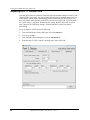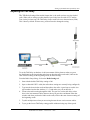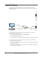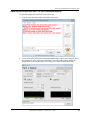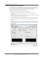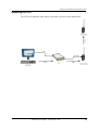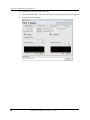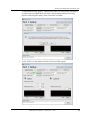
1
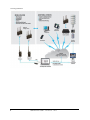
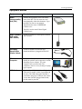
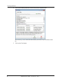
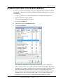
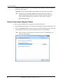
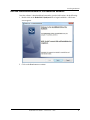
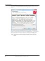
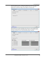
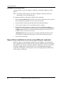
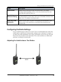
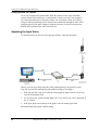
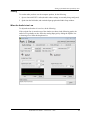
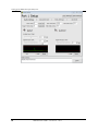
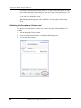
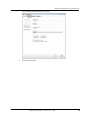
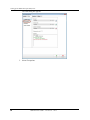
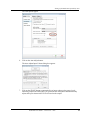
SmartMsg 7.0 RadioLink User Guide TM FEDERAL SIGNAL NOTICE Federal Signal is committed to providing documentation that provides full understanding of our software. We encourage and appreciate your comments, especially as they relate to features that require further explanation, ambiguity, inconsistencies in information or misinformation. Please e-mail your comments to us at [email protected]. This document is for informational purposes only. Federal Signal makes no warranties, express or implied, as to the information in this document. © 2013 Federal Signal Corporation All rights Reserved. 2645 Federal Signal Drive, University Park, IL 60484-3167 Phone: 708-534-3400 Website: http://www.alertnotification.net TABLE OF CONTENTS INSTALLING RADIOLINK OVERVIEW ....................................................................................................................................................................1 Equipment Needed................................................................................................................................................3 Other Requirements ..............................................................................................................................................4 Terminology ..........................................................................................................................................................4 Installation Note....................................................................................................................................................5 LICENSING RADIOLINK .....................................................................................................................................................5 INSTALLATION/ACTIVATION OF THE RADIOLINK MODULE .......................................................................................................7 Extract Compressed (Zipped) Folders ....................................................................................................................8 Run the InstallShield Wizard for the RadioLink Software .......................................................................................9 Install the USB Drivers .........................................................................................................................................13 Repeat Driver installation for all necessary USB ports (optional) ........................................................................16 SETTING UP THE RADIO INTEROPERABILITY UNIT OVERVIEW ..................................................................................................................................................................17 Equipment Needed ..............................................................................................................................................17 Other Requirements ............................................................................................................................................17 CONNECTING RADIOLINK TO A SMARTMSG SERVER .............................................................................................................18 CONFIGURING SMARTMSG SMARTCABLE SETTINGS ............................................................................................................21 Radio Username ..................................................................................................................................................21 Unique Cable Login Settings................................................................................................................................24 Licensing the SmartMsg SmartCable ..................................................................................................................27 RADIO SETTING ............................................................................................................................................................30 Radio Settings Tab ..............................................................................................................................................30 Relay Settings Tab ...............................................................................................................................................32 Advanced Settings Tab ........................................................................................................................................33 CONFIGURING THE RADIO SETTINGS .................................................................................................................................35 Adjusting the Audio between Two Radios ...........................................................................................................35 Adjusting the Input Gains....................................................................................................................................36 Adjusting the PTT Confirm Tone ..........................................................................................................................44 Adjusting the Talk Delay .....................................................................................................................................45 Adjusting the Output Gain ..................................................................................................................................46 Adjusting the VOX ...............................................................................................................................................53 Adjusting the VOX Tail ........................................................................................................................................58 Adjusting the Tail Time .......................................................................................................................................59 Adjusting the Roger Time ....................................................................................................................................60 Radio Settings Testing and Troubleshooting .......................................................................................................61 APPENDIX A – TROUBLESHOOTING PROBLEMS WITH A RADIOLINK TO SERVER CONNECTION ......................................................................................................62 INDEX .................................................................................................................................................................. 65 RadioLink User Guide – Version 3.0 – 2013 RadioLink User Guide – Version 3.0 – 2013 Installing RadioLink Installing RadioLink Overview The SmartMsg RadioLink software supports real-time, two-way radio interoperability with the SmartMsg alerting and notification system. RadioLink allows the ability to configure radios interfaced to the RIU or RIU+ (Radio Interoperability Unit). Serving as the link with the RIU or RIU+, RadioLink bridges communications between radio networks and other modes of communication capable of accessing the SmartMsg network. The integration of these devices into a SmartMsg system provides the means to do the following: Bridge communications across various radio systems consisting of different types, bands and frequencies. Extend the range of radio systems by providing repeater capabilities. Generate interoperability between two-way radio devices and other communication devices, such as phones, computers and PDAs. RadioLink User Guide – Version 3.0 – 2013 1 Installing RadioLink 2 RadioLink User Guide – Version 3.0 – 2013 Installing RadioLink Equipment Needed Equipment Description Radio Interoperability Unit (RIU) A Radio Interoperability Unit is the model name of the RIU. The two terms are used interchangeably within this document. Up to two RIUs can run on one computer. The RIU has the name CODESPEAR CSP1001 on it. The RIU+ has the name Federal Signal CSP1002 on it. Radio (800MHz, UHF and/or VHF Radios) A radio is needed for each frequency/channel that is needed. SmartMsg SmartCables (Radio Cables) A cable is needed for each radio type (brand/model) that is plugged into the RIU. Windows Computer A Windows Computer to run the SmartMsg RadioLink software and a computer to run the SmartMsg Server software. The same computer can be used for both. The computer(s) can be a server, desktop or laptop type computer. USB Cable Specifically, a USB 2.0 Cable, or Hi-Speed USB cable is needed. (Cable is provided with the unit.) The USB connected to the RIU is permitted to plug into a USB hub, but if there is more than one RIU plugged into the hub, the hub must be powered. RadioLink User Guide – Version 3.0 – 2013 3 Installing RadioLink Other Requirements RadioLinks requires uses two types of administrators to complete the software installation: Global Administrators – A Global Administrator has privileges to enter the license key for RadioLink. Windows Administrators – A Windows Administrator has access to install drivers on the computer where the installation occurs Functional USB port (on computer that will run the RadioLink software). Terminology 4 RadioLink is the software application that is used to set up radio interoperability in SmartMsg. RadioLink Module is the server-side portion of the RadioLink that interprets commands from the RadioLink software application. The RadioLink Module is accessed from CenterPoint by a Global Administrator or an authorized SmartMsg user. RIU is the brand name for the Radio Interoperability Unit. The RIU is the hardware box with four ports for radio cables and that connects to the computer through an USB cable. Docked Radio is the radio that is connected to the RIU using a SmartMsg SmartCable. Field Radio is the radio that communicates with the docked radio but is not connected by a SmartMsg SmartCable. It can be a model similar to the Docked Radio, or a different model able to communicate to the Docked Radio over the same frequency/channel. Channel is the band of frequencies through which radio audio is routed. There is often a setting or dial on the radio that allows the user to change the channel. Two radios must be on the same channel to communicate. Conventional Radio System is a system of radios that wish to communicate must be on the same channel. Trunked Radio System is a system of radios that use towers (similar to how cell phones use towers) to share frequencies. When a radio wishes to communicate with another radio, it must first send a tone to the tower which asks the tower permission to start talking on an available frequency. When the tower sends a tone back to the radio, it may begin transmitting. The tone that the tower sends to the radio is known as the Pushto-Talk Confirm Tone (PTT Confirm Tone). Repeater is the hardware that relays messages to other radios from your system to a remote destination. Its purpose is to extend the range of the broadcast. There may be multiple repeaters in a radio system depending on how large the range. Handheld (Portable) Radio is the two-way transportable communication equipment. Often times, handheld radios are carried for on-the-job communication. RadioLink User Guide – Version 3.0 – 2013 Installing RadioLink Mobile Radio is a typically vehicle-mounted transceiver used for radio communications from a vehicle. Base Station is a type of radio that is large, has great power, and has a large potential broadcast distance. There are many different kinds of base stations, but they are all mostly large stationary radios with lots of power. PTT is Push to Talk is often abbreviated as PTT. The Push To Talk button on a radio signals when to begin transmitting audio. Half-duplex is the mode used by devices that may transmit or receive audio, but not simultaneously. Half-duplex is used for most radios. Full-duplex is the mode used by devices that can transmit and receive audio simultaneously. Full-duplex is used for most cell phones. Installation Note The instructions in this document must be followed in the order indicated. It is important that the RIU is NOT connected until directed. Licensing RadioLink In order to use a SmartMsg system, you need to register various license keys in the system. There are three different types of license keys: user licenses, module licenses, and product/ plug-in licenses. All License keys are added and viewed the same way within CenterPoint. The RadioLink module is not available until a license key is entered. To license RadioLink, do the following in CenterPoint: 1. Obtain a license key from SmartMsg. 2. From CenterPoint, select Help→Licensing. The Licensing dialog box appears. Note: You must be a Global Administrator or logged in as an authorized SmartMsg user in order to access Licensing menu. 3. Enter one of the provided license key in the License Key field. RadioLink User Guide – Version 3.0 – 2013 5 Installing RadioLink 4. Click on the Add key button to save the license and its expiration data. The license key is now listed under the Summary and Active keys scroll-down menu list. 5. 6 Click on the Close button. RadioLink User Guide – Version 3.0 – 2013 Installing RadioLink Installation/Activation of the RadioLink Module In order to use a RIU, the SmartMsg server(s) must have the RadioLink Module installed and running. To determine if you have the RadioLink Module running on your system, do the following: 1. Login to CenterPoint as a Global Administrator or an authorized SmartMsg user. 2. Select CenterPoint→System Settings The Syetem Settings dialog box appears. 3. Click on the Modules tab. 4. Scroll down to find the RadioLink module. 5. Click on the OK button. If the RadioLink Module does not appear in the modules list or if it is labeled N/A under Version, perform a server update to install the RadioLink Module. The standard SmartMsg Server software installation does not include this module. RadioLink (along with other optional software modules) is available via a SmartMsg software auto update package. If performing an auto update to get the RadioLink module, restart the SmartMsg Server Service after the module update. A Server Update Package may have already been provided to you along with instructions. Otherwise, contact RadioLink User Guide – Version 3.0 – 2013 7 Installing RadioLink SmartMsg Technical Support or your SmartMsg Project Manager to obtain an update package for your system. Important: Do not connect the RIU to the computer until specified in procedures. Note: Installation of the SmartMsg RadioLink software and the device drivers requires administrative permissions on the computer. Once the software is fully installed, administrative permissions are not necessary to run the RadioLink application. Extract Compressed (Zipped) Folders If you have downloaded the file in zip format, extract the zip file first. 1. Open the RadioLink software file, and select all available files/folders within the zip file. 2. Click on the Extract button to extract the files to your desired folder location. Select the correct installer, either 32-bit or 64-bit Operating System, for your platform. Note: x86 is the same as 32-bit and x64 is the same as 64-bit. 32-bit hardware can only run 32-bit software. 8 RadioLink User Guide – Version 3.0 – 2013 Installing RadioLink Run the InstallShield Wizard for the RadioLink Software Once the software is downloaded and extracted to your desired location, do the following: 1. Double-click on the RadioLink7.0(x86).msi file to begin installation. A Welcome screen appears. 2. Click on the Next button to continue. RadioLink User Guide – Version 3.0 – 2013 9 Installing RadioLink 3. Review the software license agreement. If you agree to the terms defined, click on the option labeled “I accept the terms of the license agreement” and click on Next to continue. The default location where the RadioLink software is installed is in the following location: C:\Program Files\Federal Signal Corporation\RadioLink. You may choose a different destination location for the software by clicking on the Change button. Note: Federal Signal recommends installing SmartMsg software with default settings. 10 RadioLink User Guide – Version 3.0 – 2013 Installing RadioLink 4. Click on the Next button to continue. 5. Select Complete option button, then select the Next button to continue. If there is insufficient disk space to complete the installation, click on the Back button and select an alternative drive. RadioLink User Guide – Version 3.0 – 2013 11 Installing RadioLink 6. Click on the Install button, to begin installation. At this point files are transferred from the install package to the computer. The installation software continues to install the USB Drivers. 12 RadioLink User Guide – Version 3.0 – 2013 Installing RadioLink Install the USB Drivers Windows 7 and Server 2008 During the installation of the RadioLink hardware, two device drivers are installed and detected by Windows. To install the USB Drives for Windows 7 and server 2008, do the following: 1. Complete steps 1 through 6 in the “Run the InstallShield Wizard for the RadioLink Software” section. The Windows Security dialog box appears. 2. Select Install this driver software anyway. The Windows Security dialog box appears a second time. 3. Select Install this driver software anyway. RadioLink User Guide – Version 3.0 – 2013 13 Installing RadioLink The InstallShield Wizard Completed screen appears. 4. Click on the Finish button. Important: Do not start the SmartMsg RadioLink software until specified. 5. Connect the RIU to one of the computer’s USB ports. The following message appears. 6. Start RadioLink: START→All Programs→Federal Signal Corporation→RadioLink The following message appears. 14 RadioLink User Guide – Version 3.0 – 2013 Installing RadioLink When the Hardware Wizard is completed, the RadioLink software may instruct you to unplug the RIU and plug it back in. When doing this, make sure to connect the hardware back into the same USB port from which it was disconnected. On the Status tab, CSP 1001 Board Status shows activity as it goes through various stages detecting the hardware and loading settings. When it has completed detection and setup successfully, the CSP 1001 Board Status displays Connected. RadioLink User Guide – Version 3.0 – 2013 15 Installing RadioLink Windows XP and Server 2003 Connect the RIU to one of the computer’s USB ports. The Windows Hardware wizard appears. Note: On Windows 2000 computers, the Windows Hardware Wizard normally runs automatically, so you can skip this step. To install the USB Drive for Windows XP/2003, do the following: 1. Select No, not at this time option button. Click on the Next button. On some systems, this first dialog may not appear. If so, proceed to the next step. 2. Select Install the software automatically (Recommended) option button. 3. Click on the Next button. The wizard installs the driver software. 4. When all file transfer options are complete, you may be prompted to restart the computer. If it is not possible to restart at this time, click on the No, I will restart my computer later option button. If the final installation dialog box does not ask for a computer restart, a restart is not necessary. Authenticode Message: You may receive a message saying that the driver has not been signed with Authenticode technology. Click on the Yes button to proceed. 5. Click on the Finish button. Repeat Driver installation for all necessary USB ports (optional) Windows requires separate detection/installation for each USB port. Any time that the RIU is plugged into a specific USB port for the first time, Windows detects new hardware and requires setup. Therefore, repeat the “Install the USB Drives” section for each USB port on the computer that is used for the RIU. It is recommended that these steps be repeated for all USB ports on the computer, so that you can plug and use the RIU on any of the computer’s USB ports. 16 RadioLink User Guide – Version 3.0 – 2013 Setting up the Radio Interoperability Unit Setting up the Radio Interoperability Unit Overview The Radio Interoperability Unit (RIU) is an extremely lightweight, highly mobile device used for introducing radio system and other push-to-talk (PTT) devices into a SmartMsg system. The RIU supports radios from different manufacturers across multiple bands and frequencies and pre-defined talk groups. The SmartMsg RIU is a compact hardware appliance used with a standard PC running the SmartMsg RadioLink software. The SmartMsg RadioLink software automatically recognized the presence of the RIUs and any connected radio. All devices are connected to the RIU through SmartMsg SmartCables, which identifies the cable’s chip ID, the agency owning the cable and radio model settings. The cables automatically configure radio and agency-specific communications settings to ensure network security. The SmartMsg RIU+ combines the functionality of the base RIU with the added processing capability of a PC in a compact package. The RIU+ features the same four port radio capability as the standard RIU but does not require a user-provided PC. The RadioLink software needs to be installed first, before you set up the RIU. Refer to the “Installation/Activation of the RadioLink Module,” on page 7 for information on how to install the RadioLink software. Equipment Needed The following equipment is needed: RIU Radio SmartMsg SmartCables Windows Computer USB Cable For more information refer to the “Equipment Needed” section on page 3. Other Requirements Administrator access to CenterPoint Global Administrator access to create default port users Radio Interoperability Unit (RIU) USB 2.0 cable (provided with RIU) SmartMsg SmartCables Note: Federal Signal provides cables specific for your radio types. A cable is needed for each different radio brand/model. RadioLink User Guide – Version 3.0 – 2013 17 Setting up the Radio Interoperability Unit Functional USB port (On the computer that will run the SmartMsg RadioLink software.) After you install the RadioLink software, you need to complete the following setup. The computer that runs the RadioLink software and is connected to the RIU is referred to as the RadioLink. 1. Connect RadioLink to a SmartMsg server running the RadioLink Module. 2. Configure the SmartMsg SmartCable settings. 3. Configure each radio settings within RadioLink; this step often requires the most effort. Connecting RadioLink to a SmartMsg Server To connect the RadioLink to a SmartMsg Server running the RadioLink Module, do the following: 1. Physically connect the RIU to the computer through a USB cable. 2. Open the RadioLink. If you installed the RadioLink software to the default location, it is under START→All Programs→Federal Signal Corporation→RadioLink 3. Enter the Server Name and Port. 18 By default, the server name entered is localhost and the Port is 16887. These default settings can be used when the SmartMsg server is running on this same computer as the SmartMsg RadioLink software and where the standard SmartMsg port is used. If the SmartMsg server software is running on a different computer, the name (or IP address*) of that server must be entered in the Server Name text box. If the SmartMsg server is using a different listening port, that port is entered. Once correct Server Name and Port are entered in the appropriate fields, a Connection Status of “Connected” appears. RadioLink User Guide – Version 3.0 – 2013 Setting up the Radio Interoperability Unit 4. Confirm that the Connection Status is Connected. If you do not see this status, please refer to Appendix A, “Appendix A – Troubleshooting.” Important: Server Status must show Connected before proceeding with radio setup. *By default, computer name or host name is normally used when a client connects to a SmartMsg server. However, a system can be configured to listen on an IP address rather than a computer name. To check which is used (computer name or IP address), do the following in CenterPoint: 1. Click on the Servers tab. 2. Double-click on your server’s name. RadioLink User Guide – Version 3.0 – 2013 19 Setting up the Radio Interoperability Unit The Server Properties dialog box appears. 3. Under Listening Host Name/IP Address List, check the name used. Note: The RadioLink must connect to a SmartMsg Server that is running the RadioLink Module. 20 RadioLink User Guide – Version 3.0 – 2013 Setting up the Radio Interoperability Unit Configuring SmartMsg SmartCable Settings SmartMsg SmartCables are used to connect radios to the RIU (which connects radios to a SmartMsg system.) The SmartMsg SmartCable connects by one end to the RIU port, and the other end connects to a radio, also called the docked radio. Most portable radios connect through the headset port of the radio or the microphone jack. When you connect the cable to the RIU port, be careful not to bend the pins inside the cable. This damage can cause the cable to malfunction. Lightly push the cable into the port and slowly turn until it clicks into place. Each SmartMsg SmartCable has a special chip embedded in the cable, which identifies what type of cable it is to the SmartMsg system. This allows the SmartMsg system to detect the cable and apply the appropriate settings, regardless of which port the cable is plugged and without reconfiguration by the user each time. When a SmartMsg SmartCable is plugged into the RIU, it automatically obtains its settings from a profile contained in the SmartMsg system. This profile (of radio settings) is determined by the specific type of SmartMsg SmartCable. The type of SmartMsg SmartCable determines the settings used if a profile was previously created for this cable type. If a profile has not yet been created for this cable type, the settings associated with the RIU port are used. Radio Username Radios must be recognized as users in the SmartMsg system so that they are able to participate in chat sessions and receive alerts. When no SmartMsg SmartCable is plugged into a port, the port status displays [Disconnected]. Each time a cable is plugged into a radio port, RadioLink attempts to identify that cable. If a unique login was created for the cable, this user appears instead of [Disconnected]. RadioLink User Guide – Version 3.0 – 2013 21 Setting up the Radio Interoperability Unit The Username appears in black when the radio cable logs into SmartMsg. The Username and the Radio port number button turns blue when the radio is currently in a chat session. 22 RadioLink User Guide – Version 3.0 – 2013 Setting up the Radio Interoperability Unit The Username and the Radio port number turns green when the radio is currently receiving audio. The PTT button (Push To Talk) turns green when the docked radio is presently transmitting audio. RadioLink User Guide – Version 3.0 – 2013 23 Setting up the Radio Interoperability Unit Unique Cable Login Settings Each radio cable can be assigned unique login settings that are automatically present whenever the cable is attached to a port. Specific radio settings are associated with the user. To assign a unique login setting, do the following: 1. Attach the cable to a port on the RIU. 2. Click on the radio port button number that corresponds to the port that the cable is attached to on the RIU. For example, if you plugged in a cable to port 1, click on the 1 button. 24 RadioLink User Guide – Version 3.0 – 2013 Setting up the Radio Interoperability Unit 3. The Radio Status displays Radio unknown (login failed), because a login for this cable has not been created. 4. Click on the Associated User tab. 5. Click on the Assign a unique login for this cable button. 6. The New Radio User dialog box appears. Create a unique user login for the cable. Then, the cable is always associated with this new radio user, even if you change ports. Note: In order to set up a New Radio User, the authorized user must have permission to create new users; such as, an Administrator. 7. Enter a Username. Use a descriptive name about the cable. 8. Enter a Login and Password. You must have permission to create a new user in the SmartMsg system; such as, an administrator. RadioLink User Guide – Version 3.0 – 2013 25 Setting up the Radio Interoperability Unit 9. Click on the Create button. If the user was created successfully, a confirmation window appears. 10. Click on the OK button. The Associated User area now shows the Username of the cable. The Status Type area is populated with various types of radios compatible with this cable. 11. Adjust the Radio Settings and Relay Settings to the settings that work best for the radio type that uses this cable. (Refer to the “Radio Setting,” section on page 30 for information on individual radio settings.) 12. Repeat steps 1-11 for each different cable. 26 RadioLink User Guide – Version 3.0 – 2013 Setting up the Radio Interoperability Unit Licensing the SmartMsg SmartCable To license the newly created SmartMsg SmartCable as a licensed user within SmartMsg that is capable of sending and receiving SmartMsg notifications, do the following in CenterPoint: 1. Login to CenterPoint as a Global Administrator or an authorized SmartMsg user with permission to license users in the system. 2. Click on the SmartMsg tab. The SmartMsg window appears. 3. Click on the User License Management tab. RadioLink User Guide – Version 3.0 – 2013 27 Setting up the Radio Interoperability Unit The SmartMsg User License Management dialog box appears. 4. 28 Select the newly created radio cable. RadioLink User Guide – Version 3.0 – 2013 Setting up the Radio Interoperability Unit 5. Click on the Add button. The newly created radio cable is added to the SmartMsg enabled users list box. 6. Click on the OK button to complete the licensing. RadioLink User Guide – Version 3.0 – 2013 29 Setting up the Radio Interoperability Unit Radio Setting Different radio models/brands behave differently. For example, digital radios have varying delays while analog radios do not; some models or brands expect high volumes while others expect lower volumes. In addition, different organizations configure radios differently; therefore, even two radios of the same exact brand and model may not act the same from one organization to another, due to different configurations. Because of these variations, it is important that users have the flexibility to account for differences across their organization. Therefore, the SmartMsg RadioLink software allows for very flexible configuration of settings; such as, volume, delays, tail times, input and output gains. Radio Settings Tab Refer to the dialog box below when reviewing the terms in this section. VOX is the voice operated switch that activates transmission when sound over a certain threshold (VOX Level) is detected. 30 RadioLink User Guide – Version 3.0 – 2013 Setting up the Radio Interoperability Unit Table 1 Radio Settings Options Term Definition Range Vox Level The threshold level of audio that activates the RIU to begin transmitting. 0-128 Vox Tail The amount of time (in milliseconds) the VOX transmission remains active after audio is no longer detected. No Limit Tail Time The amount of time (in milliseconds) the radio keeps the channel open after completing transmission. 0-4999 Roger Time The amount of time (in milliseconds) the radio mutes the audio after transmitting. This is useful to avoid the radio (beep) acknowledgement that occurs with some types of radios. 0-4999 Talk Delay The amount of time (in milliseconds) the radio waits to begin transmitting audio. 0-5000 Analog Input Gain The increase/decrease in volume (in decibels) of analog audio from the radio to the RIU. This setting is used to configure the audio level coming into the RIU from the radio. 0, 14, 23 Digital Input Gain The increase/decrease in volume (in decibels) of digital audio from the RIU to the computer. This setting is used to configure the audio level coming into the computer from the RIU. -36.0-12.0 in increments of 1.5 Digital Output Gain The increase/decrease in volume (in decibels) of digital audio from the RIU to the radio. This setting is used to configure the audio level coming into the radio from the RIU. -36.0-12.0 in increments of 1.5 RadioLink User Guide – Version 3.0 – 2013 31 Setting up the Radio Interoperability Unit Relay Settings Tab There are three settings options: Audio Input, Audio Output, and Push To Talk. The default relay settings are shown in the figure below. Relay settings include Transmit, Receive, and Off. Table 2 Relay Settings Options Fields Description Transmit Determines what the RIU transmits through. Set the default relay setting to Audio Output and Push To Talk. Note: If a trunked radio is configured (Push to Talk Confirm Tone) then also check Audio Input. Receive Determines what the RIU listens for. Set the default relay setting to Audio Input. Off Turns off these options completely. 32 RadioLink User Guide – Version 3.0 – 2013 Setting up the Radio Interoperability Unit Advanced Settings Tab Refer to the dialog box below when reviewing the terms in this section. RadioLink User Guide – Version 3.0 – 2013 33 Setting up the Radio Interoperability Unit Table 3 Advanced Options Fields Description Push To Talk Confirm Tone Any types of radio systems (such as, trunked radios or Nextel walkie-talkies) that require uniform beeps before transmitting use this setting. 2QC1LB stands for 2 quick chirps, 1 long beep. When using this setting, the RIU waits until a confirm tone is heard or the Talk Delay setting is reached (whichever comes first) before transmitting. Setting the Talk Delay setting to the maximum level is recommended to allow more time for the confirm tone to be heard. This is because some radio systems have longer delays than others based upon channel availability. Duplex This depends on the radio you are using. Half-duplex is used for most radios. Full-duplex is used for most cell phones. Half-duplex is used for radios that may transmit or receive audio, but not simultaneously. Full-duplex is used for radios that can transmit and receive audio simultaneously. Default Tone Remote Control (TRC) This is used for controlling repeaters or base stations. Some organizations use an interface to control base stations hooked up to standard phone lines, which only have audio-in or audio-out. To control these radios, a tone is sent with the audio to tell the base station what channel to transmit on. There are eight channels to select from in the drop-down menu along with their corresponding frequencies. Two-Tone Remote Control Enables sending audible signals with the transmission. Some radio equipment uses these signals to change settings. Term Definition Range Frequency Displays the tones to be transmitted. 300 to 4000 in Hz Length Sets the length of the tone to be transmitted. 0 to 5000 in milliseconds Gap Defines the space between the two tones to be transmitted. 0 to 5000 in milliseconds 34 RadioLink User Guide – Version 3.0 – 2013 Setting up the Radio Interoperability Unit Fields Description Speak Events Enables radios on this port to hear Chat session events. For example, messages announcing things; such as, a new user joins the chat, leaves the chat, adds files to the file locker, etc. Enable Voice Detection Filtering Filters out any noise; such as, static, pops, crackles, hisses, or hums that are not determined to be speech. Only voice noise is transmitted, and none of the other noises. This helps to clean up the audio. Allow Play Audio Attachment Enables the drop-down list option of configuring audio attachments to play before or after an alert notification is transmitted from SmartMsg to the attached radio. Configuring the Radio Settings Set up each different type of radio one at a time. This is recommended because audio from multiple radios could interfere with each other, making it more confusing. For example, if you had Cobra radios and Motorola XTL radios, perform these steps on one type first, and then do the same procedure for the other radios. This avoids confusion as to which audio problems are coming from which radios. Adjusting the Audio between Two Radios RadioLink User Guide – Version 3.0 – 2013 35 Setting up the Radio Interoperability Unit Setting Volume on a Radio To set your volume on the docked radio. Raise the volume to 50% of the maximum volume allowed. Most radios have a volume knob. Consult your radio’s user manual if you cannot determine how to adjust the volume. You can test the volume of a radio by using two radios and listening to the volume of the transmission through the radio. After going through all of the other settings, it might be necessary to raise the volume on the docked radio up further if the audio is still too low. Adjusting the Input Gains To adjust the audio you hear over the computer speakers, adjust the input gains. Ideally, you want to get the green peaks of the graph (depicting your speech) to come close the red peak line on the Input graph without reaching or exceeding it. If the red peak line is not close to the top of the graph, the Input Gains are set too low, raise the Analog Input Gain. If it is still too low, raise the Digital Input Gain. If it is still too low, enter a multiplier in the “x” textbox. If the green peaks exceed the top of the graph, lower the Analog Input Gain. Recommended Starting Point: Default Setting 36 RadioLink User Guide – Version 3.0 – 2013 Setting up the Radio Interoperability Unit Testing To test the audio you hear over the computer speakers, do the following: 1. Open a chat with JUST 1 radio (the radio whose settings are currently being configured). 2. Speak into the field radio, and watch the Input graph on the Radio Setup window. When the Audio is too Low To adjust the audio when it is too low, do the following: If the red peak line is not at the top of the window (as shown in the following graph), the audio level is probably too low. Raise the Analog Input gain by sliding the adjuster over or choosing a level from the drop-down list. RadioLink User Guide – Version 3.0 – 2013 37 Setting up the Radio Interoperability Unit 38 RadioLink User Guide – Version 3.0 – 2013 Setting up the Radio Interoperability Unit If the green peaks do not come close to the top of the graph (as shown in the following graph), the audio is probably too low. Raise the Analog Input Gain. Slide the adjuster over OR choose a level from the drop-down list. RadioLink User Guide – Version 3.0 – 2013 39 Setting up the Radio Interoperability Unit If the Analog Input Gain is at its maximum setting (23), and the audio coming from the speakers is still too quiet, and the green peaks still do not reach come close to the top of the graph (as shown in the following graph), then and only then should you adjust the Digital Input Gain. It is not recommended to change this setting unless absolutely necessary, because it lowers the quality of the audio. 40 RadioLink User Guide – Version 3.0 – 2013 Setting up the Radio Interoperability Unit If the volume is still too low, enter a multiplier in the “X” textbox. For example, to double the input volume, enter 2 here. RadioLink User Guide – Version 3.0 – 2013 41 Setting up the Radio Interoperability Unit The following is an example of where the green peaks should be. 42 RadioLink User Guide – Version 3.0 – 2013 Setting up the Radio Interoperability Unit When the Audio is too High If you hear a popping noise coming through the computer speakers and green peaks exceed the top of the graph (sounds over modulated), the Analog Input Gain is too high. The goal is to get the green peaks as far to the end as possible without reaching the end and to hear no popping noises. Lower the Analog Input Gain. RadioLink User Guide – Version 3.0 – 2013 43 Setting up the Radio Interoperability Unit Adjusting the PTT Confirm Tone Once the Input Gains are optimized, Federal Signal recommends setting the Push To Talk Confirm Tone, if necessary. Any type of radio systems; such as, trunked radios or Nextel walkie-talkies, which require uniform beeps before transmitting use this setting. If you have one of these radio systems, set the PTT Confirm tone to 2QC1LB. 2QC1LB stands for 2 quick chirps, 1 long beep. When using this setting, the RIU waits until a confirm tone is heard or the Talk Delay setting is reached (whichever comes first) before transmitting. To set the Push To Talk Tone, do the following: 44 1. From the RadioLink Console dialog box, select the Status tab. 2. Click on your Radio. 3. From the Radio Setup dialog box, select the Advanced tab. 4. From the Push To Talk Confirm Tone drop-down, select 2QC1LB. RadioLink User Guide – Version 3.0 – 2013 Setting up the Radio Interoperability Unit Adjusting the Talk Delay The Talk Delay Setting affects Audio Output, that is, the audio you hear over the docked radio. When you are setting up radios that have previously been set with a PTT Confirm Tone (in the previous step), the Talk Delay always needs to be set to the maximum (5000). This is done by default. In most cases, you do not need to change the setting. To set the Talk Delay so that there is the least amount of delay between when you press the Send button in the chat window and when you hear the audio on the radio, while at the same time not cutting off the beginning words, do the following: From the Radio Setup dialog, click on the Radio Settings tab. 1. Start with the default Talk Delay setting at 500. 2. Open a chat with JUST 1 radio (the radio whose settings are currently being configured). 3. Type into the chat window and send the audio to the radio. A good way to test this is to type numbers into the chat window (1, 2, 3) and make sure you can hear the 1. 4. Listen to the audio coming through the radio. The goal is to set the talk delay so that there is the least amount of delay between when you press the send button in the chat window and when you hear the audio on the radio, while at the same time not cutting off the beginning words. 5. Try this multiple times when you are testing because the rate varies on some radios. 6. Try to get the lowest Talk Delay setting possible without missing any of the speech. RadioLink User Guide – Version 3.0 – 2013 45 Setting up the Radio Interoperability Unit Adjusting the Output Gain The Output Gain concerns the audio you hear over the docked radio, as seen in the diagram below. It is used to adjust the volume gain of the digital audio being transmitted from the docked radio. To adjust the Output Gain until the audio coming through the radio is clear and at a comfortable volume, do the following. 1. From the Radio Setup dialog, click on the Radio Settings tab. 2. Start with the default Output Gain at 0. 3. Open a chat with JUST 1 radio (the radio whose settings are currently being configured). You can do the next steps in the testing process in two different ways. Federal Signal recommends using the TTS method. 46 If you prefer to judge how the sound level is by ear, use the first method, “Adjusting the Output Gain with TTS.” If you prefer to see the audio waves in a graph, use the second method, “Adjusting the Output Gain with a microphone.” RadioLink User Guide – Version 3.0 – 2013 Setting up the Radio Interoperability Unit Adjusting the Output Gain with TTS (Recommended Method) To adjust the output gain with TTS, do the following: 1. Type in text in the chat window and send it to the radio. 2. Listen to the radio. If the audio coming through the radio is too loud or distorted, lower the Output Gain a few settings at a time until it is at a desirable volume. Adjust the Output Gain by moving the slider or choosing a level from the drop-down menu. RadioLink User Guide – Version 3.0 – 2013 47 Setting up the Radio Interoperability Unit For example, lower the Digital Output Gain to –4.5, and test the audio again by typing in text in the chat window and sending it to the radio. Listen on the radio to hear if it is still too loud. Keep adjusting the output gain until the audio coming through the radio is clear and at a comfortable volume. When adjusting the Output gain via this method, no activity appears on the Output Graph. Optimizing the Microphone’s Volume Level To optimize your microphone’s volume level, do the following in the SmartMsg Client window: 48 1. Start the SmartMsg Client software. 2. Login as a Global Administrator or an authorized SmartMsg user. 3. Click on the Setting button. RadioLink User Guide – Version 3.0 – 2013 Setting up the Radio Interoperability Unit The SmartMsg Settings dialog box appears. 4. Click on the Chat tab. RadioLink User Guide – Version 3.0 – 2013 49 Setting up the Radio Interoperability Unit The Chat dialog box appears. 5. 50 Select Chat options. RadioLink User Guide – Version 3.0 – 2013 Setting up the Radio Interoperability Unit The Chat options appear. 6. Click on the Auto Adjust button. The Auto Adjust Input Volume dialog box appears. 7. Click on the START button to automatically set input volume to the proper levels. SmartMsg samples the audio while you speak into the microphone and automatically adjusts the input volume and VOX level based on the sample. RadioLink User Guide – Version 3.0 – 2013 51 Setting up the Radio Interoperability Unit Adjusting the Output Gain with a Microphone This method allows you to adjust the Output Gain based upon what you see in the graph. To do this, you need a microphone. Before you start testing with a microphone, make sure that the microphone’s volume level is optimized. Refer to the “Optimizing the Microphone’s Volume Level,” section for procedures. To adjust the Output Gain with a microphone, do the following: 52 1. In a chat session with the radio, hold down the Speak button and talk into the microphone. 2. Watch the Output Graph. The goal is to get the green peaks of speech activity as close to the top of the graph as possible, without going over. 3. If the Green Peaks exceed the top of the graph, lower the Digital Output Gain setting. 4. Lower the setting one level at a time and continue to test it with the chat session until optimized. 5. If the Green Peaks do not come close to the top of the graph, raise the Digital Output Gain. Raise the setting one level at a time and continue to test it with the chat session until optimized. RadioLink User Guide – Version 3.0 – 2013 Setting up the Radio Interoperability Unit Adjusting the VOX The VOX level affects the audio output, or the audio you hear over the docked radio. RadioLink User Guide – Version 3.0 – 2013 53 Setting up the Radio Interoperability Unit To Auto Set the VOX level, do the following: 54 1. Open a chat with JUST 1 radio (the radio whose settings are currently being configured). 2. Click on the Auto Set button. RadioLink User Guide – Version 3.0 – 2013 Setting up the Radio Interoperability Unit A confirmation message appears. Make sure the radio is in a chat session, and there is no audio being transmitted. Make sure there is not any background noise that may interfere with testing this setting. Then, click on the Yes button. 3. As the VOX Level auto-adjusts itself, the VOX Level field is green. RadioLink User Guide – Version 3.0 – 2013 55 Setting up the Radio Interoperability Unit 56 4. A confirmation message appears telling you that the VOX has been adjusted. 5. Click on the OK button. 6. The VOX Level returns to a white background. RadioLink User Guide – Version 3.0 – 2013 Setting up the Radio Interoperability Unit VOX line on the Input Graph The VOX level is depicted on the Input Graph as a yellow line. Any audio below this level, is not transmitted. Only audio above the line is picked up. If you notice that the radios are picking up peripheral noises that should not be transmitted, try to set the VOX level a little higher. If you notice that the radios are not picking up normal speech when it should, try to lower the VOX level. RadioLink User Guide – Version 3.0 – 2013 57 Setting up the Radio Interoperability Unit Adjusting the VOX Tail The VOX Tail affects audio input, or audio you hear over your computer speakers. To keep the radio from cutting off audio (stop transmitting) between slow speaking while speaking into the radio, do the following: Note: Typically, the VOX Tail should be between 500 to 1500 ms. 58 1. Open a chat with JUST 1 radio (the radio whose settings are currently being configured). 2. Start with the default VOX tail setting at 1000. 3. Speak slowly into the radio. 4. Listen to the audio coming through the computer speakers. 5. If the audio is getting cut off between speaking, raise the VOX level. At the same time, make sure that this setting is not too high or the transmission is held open for a long time after done speaking. RadioLink User Guide – Version 3.0 – 2013 Setting up the Radio Interoperability Unit Adjusting the Tail Time The Tail Time setting affects audio output, or audio you hear over the radio. Keep the radio from cutting off audio (stop transmitting) between pauses between words while speaking into the computer microphone. The Tail Time affects outgoing/transmitting audio coming to the radio from a microphone or any audio transmitting out of the docked radio. To adjust the tail time, do the following: 1. Open a chat with JUST 1 radio (the radio whose settings are currently being configured). 2. Begin with the Tail Time set to the default, 500. 3. Within the chat window click on the Speak button and speak slowly into the microphone on the computer. 4. Listen to the audio coming through the radio. 5. If the audio is getting cut off between speaking, raise the tail time. At the same time make sure that this setting is not too high or the transmission is held open for a long time after done speaking. RadioLink User Guide – Version 3.0 – 2013 59 Setting up the Radio Interoperability Unit Adjusting the Roger Time The Roger Time affects audio input, or audio you hear over your computer speakers. This setting only applies to radios that have confirmation (roger) beeps or squelch sounds. The Roger Time works to negate the roger beep sound so that it is not transmitted as audio. The Roger time is the amount of audio time to ignore after transmission to eliminate the roger beep. The beep transmitting as audio is undesirable, because it might cause audio to start transmitting again after the Roger Time. The range is from 0 to 4999 milliseconds. To set Auto Set the Roger Time so that the radio does not transmit when the beep occurs, do the following: Note: Keep the Roger Time as low as possible while achieving this goal. 1. Open a chat with JUST 1 radio (the radio whose settings are currently being configured). 2. Click on the Auto Set button for the Roger Time. 3. 60 Click on the Auto Set button a few times, because variations in radios could cause the setting to change. RadioLink User Guide – Version 3.0 – 2013 Setting up the Radio Interoperability Unit Radio Settings Testing and Troubleshooting Below is a table of common troubleshooting scenarios and solutions. For each of the solutions below, adjust the settings in the way described by an increment of 1 level and then test the radio again. Scenario Solution Audio from the radio cannot be heard over the computer speakers or you have to speak loudly to get the audio to transmit. Lower the VOX Level, only as much as needed, until you can hear the transmission. Audio from the radio is polluted with background noise. Raise the VOX Level only as much as needed, until you do not hear peripheral noise anymore. Audio to the radio stops transmitting after every pause in speech. Raise the VOX Tail only as much as needed, until you do not hear the radio stopping transmission. Audio to the radio is followed by an unnecessary amount of silence. Lower the VOX Tail only as much as needed, to limit the silence. You are using a trunked radio, or if your radio takes a few seconds to begin transmissions and the first part of each audio message is being cut out. Lower the Talk Delay setting only as much as needed, until you can hear the first part of the speech. Normally, 2000 ms is a good level for trunked radios. Audio to the radio has too much of a pause at the end of the transmission. Lower the Tail Time only as much as needed, until the pause is limited. The radio uses roger beeps, and the beep is being picked up as a separate message to transmit. Raise the Roger Time only as much as needed, until you do not hear the roger beeps transmitting. Normally, 500 ms is a good level for radios with roger beeps. Audio to the radio is too soft. Increase the Output Gain setting only as much as needed, until you can hear the transmission. Audio to the radio is distorted or has static. Lower the Output Gain setting only as much as needed, until you no longer hear distortion or static. Audio from the radio is too soft. Increase the Analog Input Gain only as much as needed, until you can hear the transmission. If the volume is still too soft, try to increase the Digital Input Gain. RadioLink User Guide – Version 3.0 – 2013 61 Appendix A – Troubleshooting Appendix A – Troubleshooting Problems with a RadioLink to Server Connection If experiencing problems in obtaining a “Connected” Server Status, it is important to determine that the RadioLink can connect to a SmartMsg server where a licensed RadioLink module is enabled. Use the following troubleshooting steps. 1. Verify that the RIU is plugged into a USB port on the computer. The RIU should be plugged into a working USB port on the computer. Use the USB 2.0 (high speed) cable that was provided with the unit. If necessary, ensure that the USB port is actually operational by plugging in a different USB device (such as, a USB key drive, USB keyboard, etc.) and verifying the functionality of the device. 2. Verify proper Server Name (or IP Address*) entered in the Server Name field The Server Name (or IP address) entered in the Server Name field on the RadioLink screen must be that of a server running the SmartMsg server software. Verify that Server Name field has been entered correctly and that the SmartMsg Service is currently running on the server. * By default, computer name or host name is normally used when a client connects to a SmartMsg server. However, a system can be configured to listen on an IP address rather than a computer name. Refer to the “Connecting RadioLink to a SmartMsg Server,” section on page 18 for more information. 3. Verify Server Name/IP address is actually reachable from this computer. You can use the ping command at a DOS prompt to verify that you can actually reach the Server Name or IP address entered on the RadioLink screen. Select Run from your Start menu and type in CMD. At the DOS prompt, use the ping command to test connectivity to your server: Ping NameorIP (where NAMEorIP = the Server Name or IP address that you are testing) 4. Verify proper port number entered in the Port field. The port number entered on the RadioLink screen normally is 16887 (the default SmartMsg listening port). You only need to enter a different port if you have changed the listening port property for the SmartMsg server. 5. Verify TCP port is not blocked between the RadioLink and the SmartMsg server. If there is a firewall between the SmartMsg server and RadioLink computers, you want to ensure that the firewall is not configured to block port 16887 (or other nondefault port being used in place of 16887). In addition, you may need to verify that any local firewall software (for example, Windows XP built-in firewall) is not configured to block the port. 62 RadioLink User Guide – Version 3.0 – 2013 Appendix A – Troubleshooting 6. Verify SmartMsg Server is actually running the RadioLink module. You can verify that the server is actually running the necessary RadioLink module through CenterPoint. Refer to the “Installation/Activation of the RadioLink Module,” section for instructions on checking this. 7. Verify correct licensing of the RadioLink module on the SmartMsg Server. The RadioLink module on the Server must be licensed properly in order to allow RadioLink connections. The lack of a RadioLink license prevents a RadioLink device from being created for the radio user. To verify proper license activation for the RadioLink module, do the following: 1. Login to the CenterPoint. 2. Select Help→Licensing The Licensing dialog box appears. 3. Under the Summary Section, scroll down to RadioLink Licenses. The number of licenses used is the first number shown. The second number indicates the number of licenses available. (For example, 1/5 means one licenses is used out of the five available.) 4. The number of RIUs that can be connected to a PC is directly tied to the number allowed by the RadioLink license key. If you have maxed out the number of PCs within a SmartMsg system to which a RIU can be connected, and you wish to move the RIU to a different PC, do the following: Remove the RIU device from one of the SmartMsg PCs. Install the RIU on the new PC. Refer to Knowledge Based Article 70004 – Number of RadioLink Exceeds Licenses for more information. RadioLink User Guide – Version 3.0 – 2013 63 Appendix A – Troubleshooting 8. Verify version of the RadioLink module. If you are running an older version of the RadioLink module, you may experience problems connecting to a more current version. Contact Federal Signal Technical Support for assistance in upgrading to a more current version of the RadioLink Server module. 64 RadioLink User Guide – Version 3.0 – 2013 INDEX INDEX Extract Compressed (Zipped) Folders ................................. 8 A Activation of the RadioLink Module ...................................7 Adjusting the Audio between Two Radios ........................35 Adjusting the Input Gains .................................................36 Adjusting the Output Gain ................................................46 with a Microphone .......................................................52 with TTS .......................................................................47 Adjusting the PTT Confirm Tone .......................................44 Adjusting the Roger Time .................................................60 Adjusting the Tail Time .....................................................59 Adjusting the Talk Delay ...................................................45 Adjusting the VOX .............................................................53 Adjusting the VOX Tail ......................................................58 Advanced Settings Tab ......................................................33 Allow Play Audio Attachment ...........................................35 Analog Input Gain .............................................................31 F Federal Signal CSP1002 ...................................................... 3 Field Radio .......................................................................... 4 Frequency ......................................................................... 34 Full-duplex .......................................................................... 5 G Gap ................................................................................... 34 Global Administrator .......................................................... 4 H Half-duplex ......................................................................... 5 Handheld (Portable) Radio ................................................. 4 B I Base Station ........................................................................5 Input Gains Adjusting ..................................................................... 36 Install the USB Drivers ...................................................... 13 Installation Driver installation for all necessary USB ports ............ 16 Extract Compressed (Zipped) Folders ............................ 8 Install the USB Drives .................................................. 13 Note ............................................................................... 5 Run the InstallShield Wizard for the RadioLink Software .................................................................................. 9 Installation of the RadioLink Module ................................. 7 Installing RadioLink............................................................. 1 C Channel ...............................................................................4 CODESPEAR CSP101 ............................................................3 Configuring SmartMsg SmartCable Settings .....................21 Configuring the Radio Settings ..........................................35 Connecting RadioLink to a SmartMsg Server .....................18 Conventional Radio System ................................................4 D Default Tone Remote Control ...........................................34 Digital Input Gain ..............................................................31 Digital Output Gain ...........................................................31 Docked Radio ......................................................................4 Duplex ...............................................................................34 Length .............................................................................. 34 Licensing RadioLink ............................................................ 5 Licensing the SmartMsg SmartCable ................................ 27 E M Enable Voice Detection Filtering .......................................35 Equipment Needed .............................................................3 Mobile Radio ...................................................................... 5 L RadioLink User Guide – Version 3.0 – 2013 65 INDEX O Off .....................................................................................32 Optimizing the Microphone’s Volume Level .....................48 Overview SmartMsg .......................................................................1 P PTT ......................................................................................5 PTT Confirm Tone .............................................................34 Adjusting ......................................................................44 Push To Talk Confirm Tone ...............................................34 R Radio ...................................................................................3 Radio Cables .......................................................................3 Radio Interoperability Unit ........................................... 3, 17 Radio Setting .....................................................................30 Radio Settings Configuring...................................................................35 Radio Settings Tab.............................................................30 Radio Setup Advanced Tab...............................................................33 Associated User............................................................25 Radio Settings ........................................................ 30, 37 Relay Settings Tab ........................................................32 Radio Username ...............................................................21 RadioLink ............................................................................4 Connecting to a SmartMsg Server ...............................18 Global Administrator......................................................4 Installing .........................................................................1 Licensing ........................................................................5 WindowsAdministrator ..................................................4 RadioLink Module ...............................................................4 Activation .......................................................................7 Installation .....................................................................7 Receive..............................................................................32 Relay Settings Tab .............................................................32 Repeater .............................................................................4 Requirements ............................................................... 4, 17 RIU ............................................................................ 3, 4, 17 Roger Time ........................................................................31 Adjusting ......................................................................60 S Settings Unique Cable Login ...................................................... 24 SmartMsg Overview ....................................................................... 1 SmartMsg SmartCable Licensing ...................................................................... 27 SmartMsg SmartCable Settings Configuring .................................................................. 21 Speak Events .................................................................... 35 T Tail Time ........................................................................... 31 Talk Delay ......................................................................... 31 Terminology Base Station ................................................................... 5 Channel ......................................................................... 4 Conventional Radio System ........................................... 4 Docked Radio................................................................. 4 Field Radio ..................................................................... 4 Full-duplex ..................................................................... 5 Half-duplex .................................................................... 5 Handheld (Portable) Radio ............................................ 4 Mobile Radio ................................................................. 5 PTT ................................................................................. 5 RadioLink ....................................................................... 4 RadioLink Module .......................................................... 4 Repeater ........................................................................ 4 RIU ................................................................................. 4 Trunked Radio System ................................................... 4 Transmit ........................................................................... 32 TRC ................................................................................... 34 Trunked Radio System ........................................................ 4 Two-Tone Remote Control ............................................... 34 U Unique Cable Login Settings ............................................. 24 USB Cable ........................................................................... 3 V Volume Setting on a radio ........................................................ 36 VOX................................................................................... 30 Vox Level .......................................................................... 31 VOX line on the Input Graph ............................................ 57 Vox Tail ............................................................................. 31 Setting up the Radio Interoperability Unit ........................17 Setting up the RIU .............................................................17 Setting Volume on a radio ................................................36 66 RadioLink User Guide – Version 3.0 – 2013 INDEX W When the Audio is too High ..............................................43 When the Audio is too Low...............................................37 RadioLink User Guide – Version 3.0 – 2013 67 2645 Federal Signal Drive, University Park, IL 60484-3167 Phone: 708-534-3400 Website: http://www.alertnotification.net