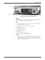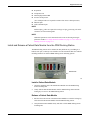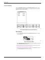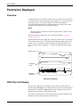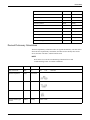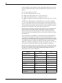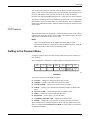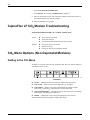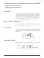
1
GE Healthcare Solar™ 8000M/i Patient Monitor Operator’s Manual Software Version 5.0 Solar™ 8000M/i English 2026266-003 (CD) 2026264-024A (paper) © 2007 General Electric Company. All rights reserved. NOTE The information in this manual only applies to Solar™ 8000M/i Patient Monitor software version 5.0. Due to continuing product innovation, specifications in this manual are subject to change without notice. NOTE For technical documentation purposes, the abbreviation GE is used for the legal entity name, GE Medical Systems Information Technologies. NOTE The Patient Data Module is described in promotional materials as CARESCAPE Patient Data Module. Listed below are GE trademarks used in this document. All other trademarks contained herein are the property of their respective owners. MUSE, QS, SOLAR, ST GUARD, TRAM, TRIM KNOB, and UNITY NETWORK are trademarks of GE Medical Systems Information Technologies registered in the United States Patent and Trademark Office. 12SL, 12RL, ApexPro, AWARE, CARESCAPE, and EK-Pro are trademarks of GE Medical Systems Information Technologies. T-2 Solar™ 8000M/i 2026265-039A 6 April 2007 Contents 1 The Basics . . . . . . . . . . . . . . . . . . . . . . . . . . . . . . . . . 1-1 About This Manual. . . . . . . . . . . . . . . . . . . . . . . . . . . . . . . . . . . . . . . . . . . . . . 1-2 Manual Purpose . . . . . . . . . . . . . . . . . . . . . . . . . . . . . . . . . . . . . . . . . . . . 1-2 Intended Audience . . . . . . . . . . . . . . . . . . . . . . . . . . . . . . . . . . . . . . . . . . . 1-2 Revision History . . . . . . . . . . . . . . . . . . . . . . . . . . . . . . . . . . . . . . . . . . . . . 1-2 Ordering Manuals . . . . . . . . . . . . . . . . . . . . . . . . . . . . . . . . . . . . . . . . . . . 1-2 Manual Conventions . . . . . . . . . . . . . . . . . . . . . . . . . . . . . . . . . . . . . . . . . . . . 1-2 Product References . . . . . . . . . . . . . . . . . . . . . . . . . . . . . . . . . . . . . . . . . . 1-2 Definitions . . . . . . . . . . . . . . . . . . . . . . . . . . . . . . . . . . . . . . . . . . . . . . . . . 1-3 Text Styles . . . . . . . . . . . . . . . . . . . . . . . . . . . . . . . . . . . . . . . . . . . . . . . . . 1-3 Illustrations and Names . . . . . . . . . . . . . . . . . . . . . . . . . . . . . . . . . . . . . . . 1-3 Software Packages. . . . . . . . . . . . . . . . . . . . . . . . . . . . . . . . . . . . . . . . . . . 1-4 Menus . . . . . . . . . . . . . . . . . . . . . . . . . . . . . . . . . . . . . . . . . . . . . . . . . . . . . . . . 1-5 Main Display . . . . . . . . . . . . . . . . . . . . . . . . . . . . . . . . . . . . . . . . . . . . . . . 1-5 More Menus . . . . . . . . . . . . . . . . . . . . . . . . . . . . . . . . . . . . . . . . . . . . . . . . 1-6 Popup Menus . . . . . . . . . . . . . . . . . . . . . . . . . . . . . . . . . . . . . . . . . . . . . . . 1-7 Subordinate Menus . . . . . . . . . . . . . . . . . . . . . . . . . . . . . . . . . . . . . . . . . . 1-8 Direct Action Menu Options . . . . . . . . . . . . . . . . . . . . . . . . . . . . . . . . . . . . 1-9 Windows . . . . . . . . . . . . . . . . . . . . . . . . . . . . . . . . . . . . . . . . . . . . . . . . . . . . . . 1-9 Parameter Windows . . . . . . . . . . . . . . . . . . . . . . . . . . . . . . . . . . . . . . . . 1-10 Maximum Display of Parameter Windows and Waveforms . . . . . . . . . . . 1-10 Information Windows . . . . . . . . . . . . . . . . . . . . . . . . . . . . . . . . . . . . . . . . 1-11 Common Operations . . . . . . . . . . . . . . . . . . . . . . . . . . . . . . . . . . . . . . . . . . . 1-12 Using the Trim Knob Control . . . . . . . . . . . . . . . . . . . . . . . . . . . . . . . . . . 1-12 Using the Touchscreen Display . . . . . . . . . . . . . . . . . . . . . . . . . . . . . . . . 1-12 Entering Alphanumeric Characters . . . . . . . . . . . . . . . . . . . . . . . . . . . . . 1-14 Setting Alarm Limits . . . . . . . . . . . . . . . . . . . . . . . . . . . . . . . . . . . . . . . . . 1-16 Selecting Options from Scroll Lists . . . . . . . . . . . . . . . . . . . . . . . . . . . . . 1-17 Language-Specific Information . . . . . . . . . . . . . . . . . . . . . . . . . . . . . . . . . . 1-18 Chinese and Japanese Language Information . . . . . . . . . . . . . . . . . . . . 1-18 French Language Information . . . . . . . . . . . . . . . . . . . . . . . . . . . . . . . . . 1-19 Hungarian, Polish and Russian Language Information . . . . . . . . . . . . . . 1-19 2 Equipment Overview . . . . . . . . . . . . . . . . . . . . . . . . . 2-1 Components. . . . . . . . . . . . . . . . . . . . . . . . . . . . . . . . . . . . . . . . . . . . . . . . . . . 2-2 Solar 8000M/i Patient Monitoring System . . . . . . . . . . . . . . . . . . . . . . . . . 2-2 Patient Data Module . . . . . . . . . . . . . . . . . . . . . . . . . . . . . . . . . . . . . . . . . . 2-5 TRAM Modules. . . . . . . . . . . . . . . . . . . . . . . . . . . . . . . . . . . . . . . . . . . . . . 2-8 Single-Parameter Modules . . . . . . . . . . . . . . . . . . . . . . . . . . . . . . . . . . . 2-11 Tram-rac Housing. . . . . . . . . . . . . . . . . . . . . . . . . . . . . . . . . . . . . . . . . . . 2-11 2026265-039A Solar™ 8000M/i i Optional Clinical Information Center . . . . . . . . . . . . . . . . . . . . . . . . . . . . 2-15 Optional Writers and Printers . . . . . . . . . . . . . . . . . . . . . . . . . . . . . . . . . 2-16 Optional Remote Display . . . . . . . . . . . . . . . . . . . . . . . . . . . . . . . . . . . . . 2-16 Optional Connectivity Device . . . . . . . . . . . . . . . . . . . . . . . . . . . . . . . . . . 2-16 Optional iPanel Computer . . . . . . . . . . . . . . . . . . . . . . . . . . . . . . . . . . . . 2-16 Controls . . . . . . . . . . . . . . . . . . . . . . . . . . . . . . . . . . . . . . . . . . . . . . . . . . . . . 2-16 Keypad and Remote Control . . . . . . . . . . . . . . . . . . . . . . . . . . . . . . . . . . 2-16 Putting the Monitor Into Operation . . . . . . . . . . . . . . . . . . . . . . . . . . . . . . . 2-18 Monitor Installation and Connection . . . . . . . . . . . . . . . . . . . . . . . . . . . . 2-18 Turning Power On . . . . . . . . . . . . . . . . . . . . . . . . . . . . . . . . . . . . . . . . . . 2-19 Performance Check . . . . . . . . . . . . . . . . . . . . . . . . . . . . . . . . . . . . . . . . . 2-20 Service PDM Message . . . . . . . . . . . . . . . . . . . . . . . . . . . . . . . . . . . . . . 2-20 3 Safety . . . . . . . . . . . . . . . . . . . . . . . . . . . . . . . . . . . . . 3-1 For Your Safety . . . . . . . . . . . . . . . . . . . . . . . . . . . . . . . . . . . . . . . . . . . . . . . . 3-2 Intended Use . . . . . . . . . . . . . . . . . . . . . . . . . . . . . . . . . . . . . . . . . . . . . . . 3-2 Intended Use of 12RL Interpolated 12-lead . . . . . . . . . . . . . . . . . . . . . . . . 3-2 Terminology . . . . . . . . . . . . . . . . . . . . . . . . . . . . . . . . . . . . . . . . . . . . . . . . 3-3 Monitor Safety . . . . . . . . . . . . . . . . . . . . . . . . . . . . . . . . . . . . . . . . . . . . . . 3-3 Classification . . . . . . . . . . . . . . . . . . . . . . . . . . . . . . . . . . . . . . . . . . . . . . 3-13 Underwriters Laboratories, Inc. . . . . . . . . . . . . . . . . . . . . . . . . . . . . . . . . 3-15 Equipment Symbols . . . . . . . . . . . . . . . . . . . . . . . . . . . . . . . . . . . . . . . . . 3-15 4 Maintenance . . . . . . . . . . . . . . . . . . . . . . . . . . . . . . . . 4-1 Biocompatibility . . . . . . . . . . . . . . . . . . . . . . . . . . . . . . . . . . . . . . . . . . . . . . . 4-2 Inspection . . . . . . . . . . . . . . . . . . . . . . . . . . . . . . . . . . . . . . . . . . . . . . . . . . . . 4-2 General Cleaning . . . . . . . . . . . . . . . . . . . . . . . . . . . . . . . . . . . . . . . . . . . . . . 4-2 Cleaning the Touchscreen . . . . . . . . . . . . . . . . . . . . . . . . . . . . . . . . . . . . . . . 4-3 Cleaning the Patient Data Module or TRAM Module . . . . . . . . . . . . . . . . . . 4-4 Cleaning Applied Parts . . . . . . . . . . . . . . . . . . . . . . . . . . . . . . . . . . . . . . . . . . 4-4 Cleaning, Disinfecting and Storing GE ECG Cables and Leadwires . . . . . 4-4 Cables and Leadwires other than GE . . . . . . . . . . . . . . . . . . . . . . . . . . . . 4-6 Other . . . . . . . . . . . . . . . . . . . . . . . . . . . . . . . . . . . . . . . . . . . . . . . . . . . . . 4-7 Internal Lithium Battery . . . . . . . . . . . . . . . . . . . . . . . . . . . . . . . . . . . . . . . . . 4-7 Technical Maintenance . . . . . . . . . . . . . . . . . . . . . . . . . . . . . . . . . . . . . . . . . 4-7 5 Monitor Setup . . . . . . . . . . . . . . . . . . . . . . . . . . . . . . 5-1 Monitor Setup Menu . . . . . . . . . . . . . . . . . . . . . . . . . . . . . . . . . . . . . . . . . . . . 5-2 Monitor Setup Menu Overview . . . . . . . . . . . . . . . . . . . . . . . . . . . . . . . . . 5-2 ii Solar™ 8000M/i 2026265-039A Waveforms On/Off . . . . . . . . . . . . . . . . . . . . . . . . . . . . . . . . . . . . . . . . . . . 5-2 Display . . . . . . . . . . . . . . . . . . . . . . . . . . . . . . . . . . . . . . . . . . . . . . . . . . . . 5-4 Color . . . . . . . . . . . . . . . . . . . . . . . . . . . . . . . . . . . . . . . . . . . . . . . . . . . . . 5-5 Parameters On/Off . . . . . . . . . . . . . . . . . . . . . . . . . . . . . . . . . . . . . . . . . . 5-7 Graph Setup . . . . . . . . . . . . . . . . . . . . . . . . . . . . . . . . . . . . . . . . . . . . . . . . 5-7 Monitor Defaults . . . . . . . . . . . . . . . . . . . . . . . . . . . . . . . . . . . . . . . . . . . . 5-11 Monitor Defaults Password. . . . . . . . . . . . . . . . . . . . . . . . . . . . . . . . . . . . 5-17 Print CRG Plus . . . . . . . . . . . . . . . . . . . . . . . . . . . . . . . . . . . . . . . . . . . . 5-18 Touchscreen Volume . . . . . . . . . . . . . . . . . . . . . . . . . . . . . . . . . . . . . . . . 5-18 Learn the Monitor . . . . . . . . . . . . . . . . . . . . . . . . . . . . . . . . . . . . . . . . . . 5-18 Software Revision . . . . . . . . . . . . . . . . . . . . . . . . . . . . . . . . . . . . . . . . . . 5-19 Service Mode . . . . . . . . . . . . . . . . . . . . . . . . . . . . . . . . . . . . . . . . . . . . . . 5-20 6 Admit/View A Patient . . . . . . . . . . . . . . . . . . . . . . . . . 6-1 About Admitting. . . . . . . . . . . . . . . . . . . . . . . . . . . . . . . . . . . . . . . . . . . . . . . . 6-2 Introduction . . . . . . . . . . . . . . . . . . . . . . . . . . . . . . . . . . . . . . . . . . . . . . . . 6-2 Auto Admit . . . . . . . . . . . . . . . . . . . . . . . . . . . . . . . . . . . . . . . . . . . . . . . . . 6-2 Monitor Applications . . . . . . . . . . . . . . . . . . . . . . . . . . . . . . . . . . . . . . . . . . 6-3 Combination Monitoring . . . . . . . . . . . . . . . . . . . . . . . . . . . . . . . . . . . . . . . 6-4 Admit Menus . . . . . . . . . . . . . . . . . . . . . . . . . . . . . . . . . . . . . . . . . . . . . . . . . . 6-8 Admit Menu Overview . . . . . . . . . . . . . . . . . . . . . . . . . . . . . . . . . . . . . . . . 6-8 Standard Admit Menu . . . . . . . . . . . . . . . . . . . . . . . . . . . . . . . . . . . . . . . . 6-8 Rover Admit Menu . . . . . . . . . . . . . . . . . . . . . . . . . . . . . . . . . . . . . . . . . . . 6-9 Combo Admit Menu . . . . . . . . . . . . . . . . . . . . . . . . . . . . . . . . . . . . . . . . . . 6-9 Rover Combo Admit Menu . . . . . . . . . . . . . . . . . . . . . . . . . . . . . . . . . . . 6-10 Admit Menu Options . . . . . . . . . . . . . . . . . . . . . . . . . . . . . . . . . . . . . . . . . . . 6-11 Change Admit Info . . . . . . . . . . . . . . . . . . . . . . . . . . . . . . . . . . . . . . . . . . 6-11 Request Admit Information . . . . . . . . . . . . . . . . . . . . . . . . . . . . . . . . . . . 6-13 ECG Source . . . . . . . . . . . . . . . . . . . . . . . . . . . . . . . . . . . . . . . . . . . . . . 6-14 Graph Location . . . . . . . . . . . . . . . . . . . . . . . . . . . . . . . . . . . . . . . . . . . . 6-14 Set Unit Name . . . . . . . . . . . . . . . . . . . . . . . . . . . . . . . . . . . . . . . . . . . . . 6-14 Set Bed Number . . . . . . . . . . . . . . . . . . . . . . . . . . . . . . . . . . . . . . . . . . . 6-14 Units of Measure . . . . . . . . . . . . . . . . . . . . . . . . . . . . . . . . . . . . . . . . . . . 6-15 Options for Admitting a Patient. . . . . . . . . . . . . . . . . . . . . . . . . . . . . . . . . 6-15 About Discharging. . . . . . . . . . . . . . . . . . . . . . . . . . . . . . . . . . . . . . . . . . . . . 6-16 Overview . . . . . . . . . . . . . . . . . . . . . . . . . . . . . . . . . . . . . . . . . . . . . . . . . 6-16 Discharge Patient — Standard and Rover Applications . . . . . . . . . . . . . 6-16 Discharge Patient — Combo and Rover Combo Applications . . . . . . . . 6-17 New Case . . . . . . . . . . . . . . . . . . . . . . . . . . . . . . . . . . . . . . . . . . . . . . . . 6-17 Viewing Other Patients . . . . . . . . . . . . . . . . . . . . . . . . . . . . . . . . . . . . . . . . . 6-18 Overview . . . . . . . . . . . . . . . . . . . . . . . . . . . . . . . . . . . . . . . . . . . . . . . . . 6-18 Automatic View On Alarm Feature . . . . . . . . . . . . . . . . . . . . . . . . . . . . . . 6-19 Viewed Patient Display . . . . . . . . . . . . . . . . . . . . . . . . . . . . . . . . . . . . . . 6-22 Monitor Setup for Viewing Other Patients. . . . . . . . . . . . . . . . . . . . . . . . . . 6-23 Default Settings . . . . . . . . . . . . . . . . . . . . . . . . . . . . . . . . . . . . . . . . . . . . 6-23 View On Alarm Options Menu Settings . . . . . . . . . . . . . . . . . . . . . . . . . . 6-26 2026265-039A Solar™ 8000M/i iii View Other Patients Menu. . . . . . . . . . . . . . . . . . . . . . . . . . . . . . . . . . . . . . . 6-26 Overview . . . . . . . . . . . . . . . . . . . . . . . . . . . . . . . . . . . . . . . . . . . . . . . . . 6-26 View Alarm . . . . . . . . . . . . . . . . . . . . . . . . . . . . . . . . . . . . . . . . . . . . . . . 6-27 View On Alarm Options . . . . . . . . . . . . . . . . . . . . . . . . . . . . . . . . . . . . . . 6-28 Select a Bed to View . . . . . . . . . . . . . . . . . . . . . . . . . . . . . . . . . . . . . . . . 6-33 Turn the View Off . . . . . . . . . . . . . . . . . . . . . . . . . . . . . . . . . . . . . . . . . . . 6-33 Select Another Care Unit . . . . . . . . . . . . . . . . . . . . . . . . . . . . . . . . . . . . . 6-33 Graph Viewed Bed . . . . . . . . . . . . . . . . . . . . . . . . . . . . . . . . . . . . . . . . . 6-33 Viewed Patient Data . . . . . . . . . . . . . . . . . . . . . . . . . . . . . . . . . . . . . . . . 6-34 Full Patient View . . . . . . . . . . . . . . . . . . . . . . . . . . . . . . . . . . . . . . . . . . . . . . 6-34 7 Printing . . . . . . . . . . . . . . . . . . . . . . . . . . . . . . . . . . . . 7-1 Writers and Printers . . . . . . . . . . . . . . . . . . . . . . . . . . . . . . . . . . . . . . . . . . . . 7-2 PRN 50 and PRN 50-M Digital Writers. . . . . . . . . . . . . . . . . . . . . . . . . . . . 7-2 Laser Printer . . . . . . . . . . . . . . . . . . . . . . . . . . . . . . . . . . . . . . . . . . . . . . . 7-4 Graphing. . . . . . . . . . . . . . . . . . . . . . . . . . . . . . . . . . . . . . . . . . . . . . . . . . . . . . 7-5 Manual Graphs . . . . . . . . . . . . . . . . . . . . . . . . . . . . . . . . . . . . . . . . . . . . . 7-5 Alarm Graphs . . . . . . . . . . . . . . . . . . . . . . . . . . . . . . . . . . . . . . . . . . . . . . 7-5 Invasive BP Only . . . . . . . . . . . . . . . . . . . . . . . . . . . . . . . . . . . . . . . . . . . . 7-6 Pressure Scales . . . . . . . . . . . . . . . . . . . . . . . . . . . . . . . . . . . . . . . . . . . . 7-6 Graphing Messages . . . . . . . . . . . . . . . . . . . . . . . . . . . . . . . . . . . . . . . . . 7-6 Graph Header . . . . . . . . . . . . . . . . . . . . . . . . . . . . . . . . . . . . . . . . . . . . . . 7-7 8 Alarm Control . . . . . . . . . . . . . . . . . . . . . . . . . . . . . . . 8-1 Smart Alarms . . . . . . . . . . . . . . . . . . . . . . . . . . . . . . . . . . . . . . . . . . . . . . . . . 8-2 Alarm Structure . . . . . . . . . . . . . . . . . . . . . . . . . . . . . . . . . . . . . . . . . . . . . . . . 8-2 Patient Status Alarms . . . . . . . . . . . . . . . . . . . . . . . . . . . . . . . . . . . . . . . . 8-2 System Status Alarms . . . . . . . . . . . . . . . . . . . . . . . . . . . . . . . . . . . . . . . . 8-3 On-screen Alarm Help . . . . . . . . . . . . . . . . . . . . . . . . . . . . . . . . . . . . . . . . 8-4 Controlling Audio Alarms . . . . . . . . . . . . . . . . . . . . . . . . . . . . . . . . . . . . . . . . 8-4 Silencing Alarms . . . . . . . . . . . . . . . . . . . . . . . . . . . . . . . . . . . . . . . . . . . . 8-4 Pausing Alarms . . . . . . . . . . . . . . . . . . . . . . . . . . . . . . . . . . . . . . . . . . . . . 8-4 Alarm Pause Breakthrough . . . . . . . . . . . . . . . . . . . . . . . . . . . . . . . . . . . . 8-5 Remote Silencing . . . . . . . . . . . . . . . . . . . . . . . . . . . . . . . . . . . . . . . . . . . 8-6 Turning Alarm Volume Off Permanently . . . . . . . . . . . . . . . . . . . . . . . . . . 8-6 Alarm Window . . . . . . . . . . . . . . . . . . . . . . . . . . . . . . . . . . . . . . . . . . . . . . . . . 8-6 Overview . . . . . . . . . . . . . . . . . . . . . . . . . . . . . . . . . . . . . . . . . . . . . . . . . . 8-6 Clear Alarms . . . . . . . . . . . . . . . . . . . . . . . . . . . . . . . . . . . . . . . . . . . . . . . 8-7 Alarm Histories . . . . . . . . . . . . . . . . . . . . . . . . . . . . . . . . . . . . . . . . . . . . . 8-7 Alarm Control Menu . . . . . . . . . . . . . . . . . . . . . . . . . . . . . . . . . . . . . . . . . . . . 8-7 Overview . . . . . . . . . . . . . . . . . . . . . . . . . . . . . . . . . . . . . . . . . . . . . . . . . . 8-7 All Limits . . . . . . . . . . . . . . . . . . . . . . . . . . . . . . . . . . . . . . . . . . . . . . . . . . . 8-8 Arrhythmia Alarm Level . . . . . . . . . . . . . . . . . . . . . . . . . . . . . . . . . . . . . . . 8-9 Parameter Alarm Level . . . . . . . . . . . . . . . . . . . . . . . . . . . . . . . . . . . . . . . 8-9 iv Solar™ 8000M/i 2026265-039A Alarm Volume . . . . . . . . . . . . . . . . . . . . . . . . . . . . . . . . . . . . . . . . . . . . . . 8-9 Alarm Help . . . . . . . . . . . . . . . . . . . . . . . . . . . . . . . . . . . . . . . . . . . . . . . . 8-10 Display Off/Alarm Pause . . . . . . . . . . . . . . . . . . . . . . . . . . . . . . . . . . . . . 8-11 Clear Alarms . . . . . . . . . . . . . . . . . . . . . . . . . . . . . . . . . . . . . . . . . . . . . . 8-12 Alarm History . . . . . . . . . . . . . . . . . . . . . . . . . . . . . . . . . . . . . . . . . . . . . . 8-12 CRG Trends . . . . . . . . . . . . . . . . . . . . . . . . . . . . . . . . . . . . . . . . . . . . . . 8-12 Alarm Pause . . . . . . . . . . . . . . . . . . . . . . . . . . . . . . . . . . . . . . . . . . . . . . 8-12 9 CRG Plus Display . . . . . . . . . . . . . . . . . . . . . . . . . . . 9-1 Parameters Displayed . . . . . . . . . . . . . . . . . . . . . . . . . . . . . . . . . . . . . . . . . . . 9-2 Overview . . . . . . . . . . . . . . . . . . . . . . . . . . . . . . . . . . . . . . . . . . . . . . . . . . 9-2 CRG Plus Full Display . . . . . . . . . . . . . . . . . . . . . . . . . . . . . . . . . . . . . . . . 9-2 CRG Plus Individual Display . . . . . . . . . . . . . . . . . . . . . . . . . . . . . . . . . . . 9-3 Turning on the CRG Plus Display . . . . . . . . . . . . . . . . . . . . . . . . . . . . . . . 9-3 Selecting Parameters for the CRG Plus Display . . . . . . . . . . . . . . . . . . . . 9-4 Printing CRG Plus Parameters . . . . . . . . . . . . . . . . . . . . . . . . . . . . . . . . . . . . 9-4 Print CRG Plus . . . . . . . . . . . . . . . . . . . . . . . . . . . . . . . . . . . . . . . . . . . . . 9-4 CRG Plus Printing Options . . . . . . . . . . . . . . . . . . . . . . . . . . . . . . . . . . . . . 9-4 CRG Trends . . . . . . . . . . . . . . . . . . . . . . . . . . . . . . . . . . . . . . . . . . . . . . . . . . . 9-6 CRG Trends Display . . . . . . . . . . . . . . . . . . . . . . . . . . . . . . . . . . . . . . . . . 9-6 CRG Trends Event Directory . . . . . . . . . . . . . . . . . . . . . . . . . . . . . . . . . . . 9-7 CRG Trends Menu Options . . . . . . . . . . . . . . . . . . . . . . . . . . . . . . . . . . . . 9-8 Document CRG Events . . . . . . . . . . . . . . . . . . . . . . . . . . . . . . . . . . . . . . . . 9-10 Troubleshooting . . . . . . . . . . . . . . . . . . . . . . . . . . . . . . . . . . . . . . . . . . . . . . 9-11 10 Patient Data . . . . . . . . . . . . . . . . . . . . . . . . . . . . . . . 10-1 Patient Data Menu . . . . . . . . . . . . . . . . . . . . . . . . . . . . . . . . . . . . . . . . . . . . . 10-2 Patient Data Menu Overview . . . . . . . . . . . . . . . . . . . . . . . . . . . . . . . . . . 10-2 Alarm History . . . . . . . . . . . . . . . . . . . . . . . . . . . . . . . . . . . . . . . . . . . . . . 10-2 Vital Signs. . . . . . . . . . . . . . . . . . . . . . . . . . . . . . . . . . . . . . . . . . . . . . . . . 10-5 Graphic Trends. . . . . . . . . . . . . . . . . . . . . . . . . . . . . . . . . . . . . . . . . . . . . 10-7 Cardiac Calcs . . . . . . . . . . . . . . . . . . . . . . . . . . . . . . . . . . . . . . . . . . . . . 10-10 Pulmonary Calcs . . . . . . . . . . . . . . . . . . . . . . . . . . . . . . . . . . . . . . . . . . 10-12 Dose Calcs . . . . . . . . . . . . . . . . . . . . . . . . . . . . . . . . . . . . . . . . . . . . . . . 10-17 CRG Trends . . . . . . . . . . . . . . . . . . . . . . . . . . . . . . . . . . . . . . . . . . . . . 10-22 11 ECG . . . . . . . . . . . . . . . . . . . . . . . . . . . . . . . . . . . . . . 11-1 Introduction . . . . . . . . . . . . . . . . . . . . . . . . . . . . . . . . . . . . . . . . . . . . . . . . . . 11-2 PDM No ECG Alarm . . . . . . . . . . . . . . . . . . . . . . . . . . . . . . . . . . . . . . . . . . . 11-2 TRAM “NO ECG” Alarm . . . . . . . . . . . . . . . . . . . . . . . . . . . . . . . . . . . . . . . . 11-3 Checklist . . . . . . . . . . . . . . . . . . . . . . . . . . . . . . . . . . . . . . . . . . . . . . . . . . . . 11-4 2026265-039A Solar™ 8000M/i v ECG Monitoring Features . . . . . . . . . . . . . . . . . . . . . . . . . . . . . . . . . . . . . . . 11-4 ECG Display . . . . . . . . . . . . . . . . . . . . . . . . . . . . . . . . . . . . . . . . . . . . . . 11-4 ECG Menu. . . . . . . . . . . . . . . . . . . . . . . . . . . . . . . . . . . . . . . . . . . . . . . . . . . . 11-5 Getting to the ECG Menu . . . . . . . . . . . . . . . . . . . . . . . . . . . . . . . . . . . . 11-5 Display Lead. . . . . . . . . . . . . . . . . . . . . . . . . . . . . . . . . . . . . . . . . . . . . . . 11-6 ECG Size . . . . . . . . . . . . . . . . . . . . . . . . . . . . . . . . . . . . . . . . . . . . . . . . . 11-8 Detect Pace . . . . . . . . . . . . . . . . . . . . . . . . . . . . . . . . . . . . . . . . . . . . . . . 11-9 ECG Limits . . . . . . . . . . . . . . . . . . . . . . . . . . . . . . . . . . . . . . . . . . . . . . . 11-13 View All ECG . . . . . . . . . . . . . . . . . . . . . . . . . . . . . . . . . . . . . . . . . . . . . 11-14 Clear V2-V6 Fail . . . . . . . . . . . . . . . . . . . . . . . . . . . . . . . . . . . . . . . . . . 11-15 Update Lead Set . . . . . . . . . . . . . . . . . . . . . . . . . . . . . . . . . . . . . . . . . . 11-15 Arrhythmia . . . . . . . . . . . . . . . . . . . . . . . . . . . . . . . . . . . . . . . . . . . . . . . 11-15 Relearn . . . . . . . . . . . . . . . . . . . . . . . . . . . . . . . . . . . . . . . . . . . . . . . . . 11-18 ST Analysis. . . . . . . . . . . . . . . . . . . . . . . . . . . . . . . . . . . . . . . . . . . . . . . 11-19 ST Analysis Menu. . . . . . . . . . . . . . . . . . . . . . . . . . . . . . . . . . . . . . . . . . 11-21 ECG Filter . . . . . . . . . . . . . . . . . . . . . . . . . . . . . . . . . . . . . . . . . . . . . . . 11-26 12 Lead ECG Analysis . . . . . . . . . . . . . . . . . . . . . . . . . . . . . . . . . . . . . . 11-27 Using 12RL Interpolated 12-lead Analysis . . . . . . . . . . . . . . . . . . . . . . 11-31 Lead Analysis . . . . . . . . . . . . . . . . . . . . . . . . . . . . . . . . . . . . . . . . . . . . . 11-36 More ECG. . . . . . . . . . . . . . . . . . . . . . . . . . . . . . . . . . . . . . . . . . . . . . . . 11-37 ECG Rate Averaging . . . . . . . . . . . . . . . . . . . . . . . . . . . . . . . . . . . . . . . . . . 11-41 Troubleshooting . . . . . . . . . . . . . . . . . . . . . . . . . . . . . . . . . . . . . . . . . . . . . 11-41 ECG Troubleshooting . . . . . . . . . . . . . . . . . . . . . . . . . . . . . . . . . . . . . . . 11-41 Pacemaker Troubleshooting . . . . . . . . . . . . . . . . . . . . . . . . . . . . . . . . . 11-43 12 Pressures . . . . . . . . . . . . . . . . . . . . . . . . . . . . . . . . . 12-1 Introduction . . . . . . . . . . . . . . . . . . . . . . . . . . . . . . . . . . . . . . . . . . . . . . . . . . 12-2 Safety . . . . . . . . . . . . . . . . . . . . . . . . . . . . . . . . . . . . . . . . . . . . . . . . . . . . . . . 12-3 Invasive Pressure Y-Adapter Cable . . . . . . . . . . . . . . . . . . . . . . . . . . . . . . 12-4 Zero Reference . . . . . . . . . . . . . . . . . . . . . . . . . . . . . . . . . . . . . . . . . . . . . . . 12-5 Checklist . . . . . . . . . . . . . . . . . . . . . . . . . . . . . . . . . . . . . . . . . . . . . . . . . . . . 12-6 Pressure Monitoring . . . . . . . . . . . . . . . . . . . . . . . . . . . . . . . . . . . . . . . . . . . 12-6 Pressure Information . . . . . . . . . . . . . . . . . . . . . . . . . . . . . . . . . . . . . . . . 12-6 Getting to the Pressure Menu . . . . . . . . . . . . . . . . . . . . . . . . . . . . . . . . . 12-7 Pressure Menu Options . . . . . . . . . . . . . . . . . . . . . . . . . . . . . . . . . . . . . . . . 12-8 Scales . . . . . . . . . . . . . . . . . . . . . . . . . . . . . . . . . . . . . . . . . . . . . . . . . . . 12-8 Full Scales . . . . . . . . . . . . . . . . . . . . . . . . . . . . . . . . . . . . . . . . . . . . . . . . 12-8 Cursor . . . . . . . . . . . . . . . . . . . . . . . . . . . . . . . . . . . . . . . . . . . . . . . . . . . 12-8 Clear Cursor . . . . . . . . . . . . . . . . . . . . . . . . . . . . . . . . . . . . . . . . . . . . . . 12-9 Limits . . . . . . . . . . . . . . . . . . . . . . . . . . . . . . . . . . . . . . . . . . . . . . . . . . . . 12-9 Change Name . . . . . . . . . . . . . . . . . . . . . . . . . . . . . . . . . . . . . . . . . . . . . 12-9 Zero . . . . . . . . . . . . . . . . . . . . . . . . . . . . . . . . . . . . . . . . . . . . . . . . . . . . 12-10 BP Filter . . . . . . . . . . . . . . . . . . . . . . . . . . . . . . . . . . . . . . . . . . . . . . . . . 12-10 vi Solar™ 8000M/i 2026265-039A Calibrate Transducer . . . . . . . . . . . . . . . . . . . . . . . . . . . . . . . . . . . . . . . 12-10 Speed . . . . . . . . . . . . . . . . . . . . . . . . . . . . . . . . . . . . . . . . . . . . . . . . . . 12-11 Special Features . . . . . . . . . . . . . . . . . . . . . . . . . . . . . . . . . . . . . . . . . . . . . 12-11 IABP . . . . . . . . . . . . . . . . . . . . . . . . . . . . . . . . . . . . . . . . . . . . . . . . . . . . 12-11 Using the IABP Feature . . . . . . . . . . . . . . . . . . . . . . . . . . . . . . . . . . . . . 12-12 Smart BP . . . . . . . . . . . . . . . . . . . . . . . . . . . . . . . . . . . . . . . . . . . . . . . . 12-13 Pulse Rate . . . . . . . . . . . . . . . . . . . . . . . . . . . . . . . . . . . . . . . . . . . . . . . 12-13 Disconnect Alarm . . . . . . . . . . . . . . . . . . . . . . . . . . . . . . . . . . . . . . . . . 12-13 PA Wedge . . . . . . . . . . . . . . . . . . . . . . . . . . . . . . . . . . . . . . . . . . . . . . . . . . . 12-14 Overview . . . . . . . . . . . . . . . . . . . . . . . . . . . . . . . . . . . . . . . . . . . . . . . . 12-14 PA Wedge Menu Option . . . . . . . . . . . . . . . . . . . . . . . . . . . . . . . . . . . . 12-14 PA Insert Wedge Menu Option. . . . . . . . . . . . . . . . . . . . . . . . . . . . . . . . 12-15 Troubleshooting . . . . . . . . . . . . . . . . . . . . . . . . . . . . . . . . . . . . . . . . . . . . . 12-21 “Pressure” Message Appearing When Zeroing Invasive Pressure Lines . . . . . . . . . . . . . . . . . . . . . . . . . . . . . . . . . . . . . . . . . . . . 12-21 13 NBP . . . . . . . . . . . . . . . . . . . . . . . . . . . . . . . . . . . . . . 13-1 Introduction . . . . . . . . . . . . . . . . . . . . . . . . . . . . . . . . . . . . . . . . . . . . . . . . . . 13-2 NBP Connectors . . . . . . . . . . . . . . . . . . . . . . . . . . . . . . . . . . . . . . . . . . . 13-2 Safety . . . . . . . . . . . . . . . . . . . . . . . . . . . . . . . . . . . . . . . . . . . . . . . . . . . . . . . 13-3 NBP Technologies . . . . . . . . . . . . . . . . . . . . . . . . . . . . . . . . . . . . . . . . . . . . 13-4 Checklist . . . . . . . . . . . . . . . . . . . . . . . . . . . . . . . . . . . . . . . . . . . . . . . . . . . . 13-5 NBP Monitoring Features . . . . . . . . . . . . . . . . . . . . . . . . . . . . . . . . . . . . . . . 13-6 NBP Information . . . . . . . . . . . . . . . . . . . . . . . . . . . . . . . . . . . . . . . . . . . . 13-6 Getting to the NBP Menu . . . . . . . . . . . . . . . . . . . . . . . . . . . . . . . . . . . . . 13-8 NBP Menu Options . . . . . . . . . . . . . . . . . . . . . . . . . . . . . . . . . . . . . . . . . . . . 13-9 NBP Auto . . . . . . . . . . . . . . . . . . . . . . . . . . . . . . . . . . . . . . . . . . . . . . . . . 13-9 NBP Stat . . . . . . . . . . . . . . . . . . . . . . . . . . . . . . . . . . . . . . . . . . . . . . . . 13-10 Review NBPs . . . . . . . . . . . . . . . . . . . . . . . . . . . . . . . . . . . . . . . . . . . . . 13-11 NBP Limits . . . . . . . . . . . . . . . . . . . . . . . . . . . . . . . . . . . . . . . . . . . . . . . 13-11 Cuff Size . . . . . . . . . . . . . . . . . . . . . . . . . . . . . . . . . . . . . . . . . . . . . . . . 13-11 Clear NBP Reading . . . . . . . . . . . . . . . . . . . . . . . . . . . . . . . . . . . . . . . . 13-11 Initial Inflation Pressure . . . . . . . . . . . . . . . . . . . . . . . . . . . . . . . . . . . . . 13-11 Custom Defaults . . . . . . . . . . . . . . . . . . . . . . . . . . . . . . . . . . . . . . . . . . . . . 13-12 Auto NBP Cancellation Notification . . . . . . . . . . . . . . . . . . . . . . . . . . . . 13-12 Extended NBP Alarm Silence . . . . . . . . . . . . . . . . . . . . . . . . . . . . . . . . 13-12 Troubleshooting . . . . . . . . . . . . . . . . . . . . . . . . . . . . . . . . . . . . . . . . . . . . . 13-13 NBP Status Messages . . . . . . . . . . . . . . . . . . . . . . . . . . . . . . . . . . . . . . 13-13 2026265-039A Solar™ 8000M/i vii 14 SpO2 . . . . . . . . . . . . . . . . . . . . . . . . . . . . . . . . . . . . . 14-1 Introduction . . . . . . . . . . . . . . . . . . . . . . . . . . . . . . . . . . . . . . . . . . . . . . . . . . 14-2 Safety . . . . . . . . . . . . . . . . . . . . . . . . . . . . . . . . . . . . . . . . . . . . . . . . . . . . . . . 14-4 Safety Messages . . . . . . . . . . . . . . . . . . . . . . . . . . . . . . . . . . . . . . . . . . . 14-4 Measurements . . . . . . . . . . . . . . . . . . . . . . . . . . . . . . . . . . . . . . . . . . . . . 14-6 Neonates and Infants . . . . . . . . . . . . . . . . . . . . . . . . . . . . . . . . . . . . . . . . 14-6 Checklist . . . . . . . . . . . . . . . . . . . . . . . . . . . . . . . . . . . . . . . . . . . . . . . . . . . . 14-7 Masimo SET Module . . . . . . . . . . . . . . . . . . . . . . . . . . . . . . . . . . . . . . . . . . . 14-7 No Implied License . . . . . . . . . . . . . . . . . . . . . . . . . . . . . . . . . . . . . . . . . 14-7 Masimo SET Module PWR Indicator Light . . . . . . . . . . . . . . . . . . . . . . . 14-7 SpO2 Monitoring Features . . . . . . . . . . . . . . . . . . . . . . . . . . . . . . . . . . . . . . 14-8 SpO2 Information . . . . . . . . . . . . . . . . . . . . . . . . . . . . . . . . . . . . . . . . . . 14-8 Getting to the SpO2 Menu . . . . . . . . . . . . . . . . . . . . . . . . . . . . . . . . . . . . 14-9 SpO2 Menu Options . . . . . . . . . . . . . . . . . . . . . . . . . . . . . . . . . . . . . . . . . . 14-10 Size . . . . . . . . . . . . . . . . . . . . . . . . . . . . . . . . . . . . . . . . . . . . . . . . . . . . 14-10 Rate . . . . . . . . . . . . . . . . . . . . . . . . . . . . . . . . . . . . . . . . . . . . . . . . . . . . 14-11 Rate Volume . . . . . . . . . . . . . . . . . . . . . . . . . . . . . . . . . . . . . . . . . . . . . 14-11 SpO2 Limits . . . . . . . . . . . . . . . . . . . . . . . . . . . . . . . . . . . . . . . . . . . . . . 14-11 Sat-Seconds . . . . . . . . . . . . . . . . . . . . . . . . . . . . . . . . . . . . . . . . . . . . . 14-12 Persistent . . . . . . . . . . . . . . . . . . . . . . . . . . . . . . . . . . . . . . . . . . . . . . . . 14-12 Response . . . . . . . . . . . . . . . . . . . . . . . . . . . . . . . . . . . . . . . . . . . . . . . 14-12 Speed . . . . . . . . . . . . . . . . . . . . . . . . . . . . . . . . . . . . . . . . . . . . . . . . . . 14-13 Sensitivity . . . . . . . . . . . . . . . . . . . . . . . . . . . . . . . . . . . . . . . . . . . . . . . 14-13 Averaging . . . . . . . . . . . . . . . . . . . . . . . . . . . . . . . . . . . . . . . . . . . . . . . 14-13 SpO2 System Alarms . . . . . . . . . . . . . . . . . . . . . . . . . . . . . . . . . . . . . . . . . 14-13 Probe Off Patient Condition . . . . . . . . . . . . . . . . . . . . . . . . . . . . . . . . . . 14-13 Connect SpO2 Probe Condition . . . . . . . . . . . . . . . . . . . . . . . . . . . . . . 14-14 Pulse Search Condition . . . . . . . . . . . . . . . . . . . . . . . . . . . . . . . . . . . . . 14-14 Troubleshooting . . . . . . . . . . . . . . . . . . . . . . . . . . . . . . . . . . . . . . . . . . . . . 14-14 SpO2 Messages . . . . . . . . . . . . . . . . . . . . . . . . . . . . . . . . . . . . . . . . . . . 14-14 15 Cardiac Output . . . . . . . . . . . . . . . . . . . . . . . . . . . . . 15-1 Introduction . . . . . . . . . . . . . . . . . . . . . . . . . . . . . . . . . . . . . . . . . . . . . . . . . . 15-2 Cardiac Output Overview . . . . . . . . . . . . . . . . . . . . . . . . . . . . . . . . . . . . 15-2 Influencing Factors . . . . . . . . . . . . . . . . . . . . . . . . . . . . . . . . . . . . . . . . . 15-3 Suggested Cardiac Output Procedure . . . . . . . . . . . . . . . . . . . . . . . . . . . . 15-3 Checklist . . . . . . . . . . . . . . . . . . . . . . . . . . . . . . . . . . . . . . . . . . . . . . . . . . . . 15-5 Cardiac Output Monitoring Features . . . . . . . . . . . . . . . . . . . . . . . . . . . . . . 15-5 Cardiac Output Information . . . . . . . . . . . . . . . . . . . . . . . . . . . . . . . . . . . 15-5 Cardiac Output Trials . . . . . . . . . . . . . . . . . . . . . . . . . . . . . . . . . . . . . . . . 15-6 viii Solar™ 8000M/i 2026265-039A Getting to the Cardiac Output Menu . . . . . . . . . . . . . . . . . . . . . . . . . . . . 15-7 Cardiac Output Menu Options . . . . . . . . . . . . . . . . . . . . . . . . . . . . . . . . . . . 15-8 Delete CO Trials . . . . . . . . . . . . . . . . . . . . . . . . . . . . . . . . . . . . . . . . . . . 15-8 Cardiac Calcs . . . . . . . . . . . . . . . . . . . . . . . . . . . . . . . . . . . . . . . . . . . . . . 15-9 Cardiac Output Now . . . . . . . . . . . . . . . . . . . . . . . . . . . . . . . . . . . . . . . 15-11 BT Limits . . . . . . . . . . . . . . . . . . . . . . . . . . . . . . . . . . . . . . . . . . . . . . . . 15-11 Print CO Curve . . . . . . . . . . . . . . . . . . . . . . . . . . . . . . . . . . . . . . . . . . . 15-11 Auto Mode . . . . . . . . . . . . . . . . . . . . . . . . . . . . . . . . . . . . . . . . . . . . . . . 15-12 Use: PAW (PAD, LA) . . . . . . . . . . . . . . . . . . . . . . . . . . . . . . . . . . . . . . . 15-12 Catheter . . . . . . . . . . . . . . . . . . . . . . . . . . . . . . . . . . . . . . . . . . . . . . . . . 15-12 Injectate Temperature . . . . . . . . . . . . . . . . . . . . . . . . . . . . . . . . . . . . . . 15-13 Size . . . . . . . . . . . . . . . . . . . . . . . . . . . . . . . . . . . . . . . . . . . . . . . . . . . . 15-13 Injectate Volume . . . . . . . . . . . . . . . . . . . . . . . . . . . . . . . . . . . . . . . . . . 15-13 Computation Constant . . . . . . . . . . . . . . . . . . . . . . . . . . . . . . . . . . . . . . 15-14 Cardiac Output Help . . . . . . . . . . . . . . . . . . . . . . . . . . . . . . . . . . . . . . . 15-14 Troubleshooting . . . . . . . . . . . . . . . . . . . . . . . . . . . . . . . . . . . . . . . . . . . . . 15-14 Procedural Prompts and Messages . . . . . . . . . . . . . . . . . . . . . . . . . . . 15-14 Error Messages . . . . . . . . . . . . . . . . . . . . . . . . . . . . . . . . . . . . . . . . . . . 15-15 16 Respiration . . . . . . . . . . . . . . . . . . . . . . . . . . . . . . . . 16-1 Introduction . . . . . . . . . . . . . . . . . . . . . . . . . . . . . . . . . . . . . . . . . . . . . . . . . . 16-2 Respiration Overview . . . . . . . . . . . . . . . . . . . . . . . . . . . . . . . . . . . . . . . 16-2 No Breath and Apnea Events . . . . . . . . . . . . . . . . . . . . . . . . . . . . . . . . . 16-2 General Information . . . . . . . . . . . . . . . . . . . . . . . . . . . . . . . . . . . . . . . . . 16-3 Checklist . . . . . . . . . . . . . . . . . . . . . . . . . . . . . . . . . . . . . . . . . . . . . . . . . . . . 16-5 Respiration Monitoring Features . . . . . . . . . . . . . . . . . . . . . . . . . . . . . . . . . 16-5 Respiration Information . . . . . . . . . . . . . . . . . . . . . . . . . . . . . . . . . . . . . . 16-5 Getting to the Respiration Menu . . . . . . . . . . . . . . . . . . . . . . . . . . . . . . . 16-5 Respiration Menu Options . . . . . . . . . . . . . . . . . . . . . . . . . . . . . . . . . . . . . . 16-6 Lead . . . . . . . . . . . . . . . . . . . . . . . . . . . . . . . . . . . . . . . . . . . . . . . . . . . . . 16-6 Relearn Respiration . . . . . . . . . . . . . . . . . . . . . . . . . . . . . . . . . . . . . . . . . 16-7 Sensitivity . . . . . . . . . . . . . . . . . . . . . . . . . . . . . . . . . . . . . . . . . . . . . . . . 16-7 Respiration Limits . . . . . . . . . . . . . . . . . . . . . . . . . . . . . . . . . . . . . . . . . . 16-7 Auto Size . . . . . . . . . . . . . . . . . . . . . . . . . . . . . . . . . . . . . . . . . . . . . . . . . 16-8 Manual Size . . . . . . . . . . . . . . . . . . . . . . . . . . . . . . . . . . . . . . . . . . . . . . . 16-8 Cardiac Artifact Alarm . . . . . . . . . . . . . . . . . . . . . . . . . . . . . . . . . . . . . . . 16-8 Speed . . . . . . . . . . . . . . . . . . . . . . . . . . . . . . . . . . . . . . . . . . . . . . . . . . . 16-9 Troubleshooting . . . . . . . . . . . . . . . . . . . . . . . . . . . . . . . . . . . . . . . . . . . . . . 16-9 Messages . . . . . . . . . . . . . . . . . . . . . . . . . . . . . . . . . . . . . . . . . . . . . . . . 16-9 17 Temperature . . . . . . . . . . . . . . . . . . . . . . . . . . . . . . . 17-1 Introduction . . . . . . . . . . . . . . . . . . . . . . . . . . . . . . . . . . . . . . . . . . . . . . . . . . 17-2 Checklist . . . . . . . . . . . . . . . . . . . . . . . . . . . . . . . . . . . . . . . . . . . . . . . . . . . . 17-2 2026265-039A Solar™ 8000M/i ix Temperature Monitoring Features . . . . . . . . . . . . . . . . . . . . . . . . . . . . . . . . 17-3 Temperature Information . . . . . . . . . . . . . . . . . . . . . . . . . . . . . . . . . . . . . 17-3 Getting to the Temperature Menu . . . . . . . . . . . . . . . . . . . . . . . . . . . . . . 17-4 Temperature Menu Options . . . . . . . . . . . . . . . . . . . . . . . . . . . . . . . . . . . . . 17-4 T1 . . . . . . . . . . . . . . . . . . . . . . . . . . . . . . . . . . . . . . . . . . . . . . . . . . . . . . 17-4 T2 . . . . . . . . . . . . . . . . . . . . . . . . . . . . . . . . . . . . . . . . . . . . . . . . . . . . . . 17-5 Units . . . . . . . . . . . . . . . . . . . . . . . . . . . . . . . . . . . . . . . . . . . . . . . . . . . . 17-5 Temperature Limits . . . . . . . . . . . . . . . . . . . . . . . . . . . . . . . . . . . . . . . . . 17-5 Select Default Temperature Site Labels . . . . . . . . . . . . . . . . . . . . . . . . . . . 17-5 Troubleshooting . . . . . . . . . . . . . . . . . . . . . . . . . . . . . . . . . . . . . . . . . . . . . . 17-5 Messages . . . . . . . . . . . . . . . . . . . . . . . . . . . . . . . . . . . . . . . . . . . . . . . . 17-5 18 SvO2 . . . . . . . . . . . . . . . . . . . . . . . . . . . . . . . . . . . . . 18-1 Introduction . . . . . . . . . . . . . . . . . . . . . . . . . . . . . . . . . . . . . . . . . . . . . . . . . . 18-2 Checklist . . . . . . . . . . . . . . . . . . . . . . . . . . . . . . . . . . . . . . . . . . . . . . . . . . . . 18-2 SvO2 Monitoring Features . . . . . . . . . . . . . . . . . . . . . . . . . . . . . . . . . . . . . . 18-3 SvO2 Information . . . . . . . . . . . . . . . . . . . . . . . . . . . . . . . . . . . . . . . . . . . 18-3 Getting to the SvO2 Menu . . . . . . . . . . . . . . . . . . . . . . . . . . . . . . . . . . . . 18-3 SvO2 Menu Options. . . . . . . . . . . . . . . . . . . . . . . . . . . . . . . . . . . . . . . . . . . . 18-4 SvO2 Limits . . . . . . . . . . . . . . . . . . . . . . . . . . . . . . . . . . . . . . . . . . . . . . . 18-4 SvO2 Help . . . . . . . . . . . . . . . . . . . . . . . . . . . . . . . . . . . . . . . . . . . . . . . . 18-4 Preinsertion Calibration . . . . . . . . . . . . . . . . . . . . . . . . . . . . . . . . . . . . . . 18-4 Light Intensity Calibration . . . . . . . . . . . . . . . . . . . . . . . . . . . . . . . . . . . . 18-5 Calibrate to Venous Blood Gas . . . . . . . . . . . . . . . . . . . . . . . . . . . . . . . . 18-5 SvO2 Cal History . . . . . . . . . . . . . . . . . . . . . . . . . . . . . . . . . . . . . . . . . . . 18-5 Calibration . . . . . . . . . . . . . . . . . . . . . . . . . . . . . . . . . . . . . . . . . . . . . . . . . . . 18-5 Calibration Overview . . . . . . . . . . . . . . . . . . . . . . . . . . . . . . . . . . . . . . . . 18-5 Preinsertion Calibration . . . . . . . . . . . . . . . . . . . . . . . . . . . . . . . . . . . . . . 18-5 Light Intensity Calibration . . . . . . . . . . . . . . . . . . . . . . . . . . . . . . . . . . . . 18-6 Calibrate to Venous Blood Gas . . . . . . . . . . . . . . . . . . . . . . . . . . . . . . . . 18-6 SvO2 Cal History . . . . . . . . . . . . . . . . . . . . . . . . . . . . . . . . . . . . . . . . . . . 18-8 Troubleshooting . . . . . . . . . . . . . . . . . . . . . . . . . . . . . . . . . . . . . . . . . . . . . . 18-9 PREINSERT CAL FAIL Message . . . . . . . . . . . . . . . . . . . . . . . . . . . . . . 18-9 LOW LIGHT or NO LIGHT Message . . . . . . . . . . . . . . . . . . . . . . . . . . . . 18-9 SERVICE MODULE Message . . . . . . . . . . . . . . . . . . . . . . . . . . . . . . . . 18-10 X Displayed in SvO2 Parameter Window . . . . . . . . . . . . . . . . . . . . . . . 18-10 19 CO2 . . . . . . . . . . . . . . . . . . . . . . . . . . . . . . . . . . . . . . 19-1 Introduction . . . . . . . . . . . . . . . . . . . . . . . . . . . . . . . . . . . . . . . . . . . . . . . . . . 19-2 Safety . . . . . . . . . . . . . . . . . . . . . . . . . . . . . . . . . . . . . . . . . . . . . . . . . . . . . . . 19-2 x Solar™ 8000M/i 2026265-039A CO2 Monitoring Features . . . . . . . . . . . . . . . . . . . . . . . . . . . . . . . . . . . . . . . 19-4 CO2 Information . . . . . . . . . . . . . . . . . . . . . . . . . . . . . . . . . . . . . . . . . . . 19-4 Capnostat Modules . . . . . . . . . . . . . . . . . . . . . . . . . . . . . . . . . . . . . . . . . . . . 19-5 General Information . . . . . . . . . . . . . . . . . . . . . . . . . . . . . . . . . . . . . . . . . 19-5 CO2 Menu Options (Capnostat Modules) . . . . . . . . . . . . . . . . . . . . . . . . . . 19-7 Getting to the CO2 Menu . . . . . . . . . . . . . . . . . . . . . . . . . . . . . . . . . . . . . 19-7 Pump . . . . . . . . . . . . . . . . . . . . . . . . . . . . . . . . . . . . . . . . . . . . . . . . . . . . 19-8 Units . . . . . . . . . . . . . . . . . . . . . . . . . . . . . . . . . . . . . . . . . . . . . . . . . . . . 19-8 CO2 Scale . . . . . . . . . . . . . . . . . . . . . . . . . . . . . . . . . . . . . . . . . . . . . . . . 19-8 CO2 Limits . . . . . . . . . . . . . . . . . . . . . . . . . . . . . . . . . . . . . . . . . . . . . . . . 19-8 N2O Compensation . . . . . . . . . . . . . . . . . . . . . . . . . . . . . . . . . . . . . . . . . 19-9 O2 Compensation . . . . . . . . . . . . . . . . . . . . . . . . . . . . . . . . . . . . . . . . . . 19-9 CO2 Averaging . . . . . . . . . . . . . . . . . . . . . . . . . . . . . . . . . . . . . . . . . . . . 19-9 Cal Sensor to Zero Cell . . . . . . . . . . . . . . . . . . . . . . . . . . . . . . . . . . . . . . 19-9 Calibrate Adapter . . . . . . . . . . . . . . . . . . . . . . . . . . . . . . . . . . . . . . . . . . 19-10 Speed . . . . . . . . . . . . . . . . . . . . . . . . . . . . . . . . . . . . . . . . . . . . . . . . . . 19-10 Zero the Capnostat Sensor . . . . . . . . . . . . . . . . . . . . . . . . . . . . . . . . . . . . 19-10 Calibrate the Capnostat Adapter . . . . . . . . . . . . . . . . . . . . . . . . . . . . . . . . 19-11 Capnostat Sensor and Adapter Cleaning . . . . . . . . . . . . . . . . . . . . . . . . . 19-11 Cleaning the Capnostat Sensor . . . . . . . . . . . . . . . . . . . . . . . . . . . . . . . 19-11 Cleaning the Reusable Capnostat Adapters . . . . . . . . . . . . . . . . . . . . . 19-11 Capnostat Sensor Troubleshooting. . . . . . . . . . . . . . . . . . . . . . . . . . . . . . 19-12 Messages . . . . . . . . . . . . . . . . . . . . . . . . . . . . . . . . . . . . . . . . . . . . . . . 19-12 Sidestream Modules . . . . . . . . . . . . . . . . . . . . . . . . . . . . . . . . . . . . . . . . . . 19-14 Pump Control . . . . . . . . . . . . . . . . . . . . . . . . . . . . . . . . . . . . . . . . . . . . . 19-14 CapnoFlex LF CO2 Module . . . . . . . . . . . . . . . . . . . . . . . . . . . . . . . . . . . . 19-15 CapnoFlex LF CO2 Module Troubleshooting . . . . . . . . . . . . . . . . . . . . . . 19-16 CO2 Menu Options (Non-Capnostat Modules) . . . . . . . . . . . . . . . . . . . . . 19-16 Getting to the CO2 Menu . . . . . . . . . . . . . . . . . . . . . . . . . . . . . . . . . . . . 19-16 Units . . . . . . . . . . . . . . . . . . . . . . . . . . . . . . . . . . . . . . . . . . . . . . . . . . . 19-17 CO2 Scale . . . . . . . . . . . . . . . . . . . . . . . . . . . . . . . . . . . . . . . . . . . . . . . 19-17 CO2 Limits . . . . . . . . . . . . . . . . . . . . . . . . . . . . . . . . . . . . . . . . . . . . . . . 19-17 N2O Compensation . . . . . . . . . . . . . . . . . . . . . . . . . . . . . . . . . . . . . . . . 19-17 Speed . . . . . . . . . . . . . . . . . . . . . . . . . . . . . . . . . . . . . . . . . . . . . . . . . . 19-18 20 Interfaces . . . . . . . . . . . . . . . . . . . . . . . . . . . . . . . . . 20-1 Introduction . . . . . . . . . . . . . . . . . . . . . . . . . . . . . . . . . . . . . . . . . . . . . . . . . . 20-2 Safety . . . . . . . . . . . . . . . . . . . . . . . . . . . . . . . . . . . . . . . . . . . . . . . . . . . . . . . 20-5 Interconnection . . . . . . . . . . . . . . . . . . . . . . . . . . . . . . . . . . . . . . . . . . . . . . . 20-6 2026265-039A Solar™ 8000M/i xi Serial Port Indicator Lights . . . . . . . . . . . . . . . . . . . . . . . . . . . . . . . . . . . . . 20-7 Displayed Data . . . . . . . . . . . . . . . . . . . . . . . . . . . . . . . . . . . . . . . . . . . . . . . . 20-8 Displayed Data Overview . . . . . . . . . . . . . . . . . . . . . . . . . . . . . . . . . . . . 20-8 Parameters . . . . . . . . . . . . . . . . . . . . . . . . . . . . . . . . . . . . . . . . . . . . . . . 20-9 Parameter Windows and Menus . . . . . . . . . . . . . . . . . . . . . . . . . . . . . . . 20-9 Software Compatibility . . . . . . . . . . . . . . . . . . . . . . . . . . . . . . . . . . . . . . . . 20-14 Device-Specific Information . . . . . . . . . . . . . . . . . . . . . . . . . . . . . . . . . . . . 20-14 Dräger Fabius GS Ventilators . . . . . . . . . . . . . . . . . . . . . . . . . . . . . . . . 20-14 Dräger Ventilators . . . . . . . . . . . . . . . . . . . . . . . . . . . . . . . . . . . . . . . . . 20-14 Siemens Servo-i Ventilators . . . . . . . . . . . . . . . . . . . . . . . . . . . . . . . . . 20-15 Siemens Servo 300 Ventilators . . . . . . . . . . . . . . . . . . . . . . . . . . . . . . . 20-15 Siemens Servo 900C/D/E Ventilators . . . . . . . . . . . . . . . . . . . . . . . . . . 20-15 Alaris Medical Systems 7130 and 7230 Infusion Pumps . . . . . . . . . . . . 20-15 Linde MicroGas 7650 Transcutaneous Monitors . . . . . . . . . . . . . . . . . . 20-16 Baxter Edwards Critical-Care Vigilance Monitors . . . . . . . . . . . . . . . . . 20-16 A Appendix A — Adult-ICU Mode Defaults . . . . . . . . . A-1 Adult-ICU Mode Defaults . . . . . . . . . . . . . . . . . . . . . . . . . . . . . . . . . . . . . . . A-2 B Appendix B — Neonatal-ICU Mode Defaults . . . . . . B-1 Neonatal-ICU Mode Defaults . . . . . . . . . . . . . . . . . . . . . . . . . . . . . . . . . . . . B-2 C Appendix C— Operating Room Mode Defaults . . . C-1 Operating Room Mode Defaults . . . . . . . . . . . . . . . . . . . . . . . . . . . . . . . . . C-2 D Appendix D — Monitor Defaults Worksheet . . . . . . D-1 Monitor Defaults Worksheet . . . . . . . . . . . . . . . . . . . . . . . . . . . . . . . . . . . . D-2 E Appendix E — Analog Output . . . . . . . . . . . . . . . . . E-1 Analog Output . . . . . . . . . . . . . . . . . . . . . . . . . . . . . . . . . . . . . . . . . . . . . . . . E-2 Overview . . . . . . . . . . . . . . . . . . . . . . . . . . . . . . . . . . . . . . . . . . . . . . . . . . E-2 Acquisition Modules . . . . . . . . . . . . . . . . . . . . . . . . . . . . . . . . . . . . . . . . . . E-2 Tram-rac Housing . . . . . . . . . . . . . . . . . . . . . . . . . . . . . . . . . . . . . . . . . . . E-3 F Appendix F — Supplies Information . . . . . . . . . . . . F-1 Appendix F — Supplies Information . . . . . . . . . . . . . . . . . . . . . . . . . . . . . . F-2 xii Solar™ 8000M/i 2026265-039A G Appendix G — Software Packages . . . . . . . . . . . . . G-1 Software Packages . . . . . . . . . . . . . . . . . . . . . . . . . . . . . . . . . . . . . . . . . . . . G-2 H Appendix H — Technical Specifications . . . . . . . . . H-1 Solar 8000M/i Patient Monitor . . . . . . . . . . . . . . . . . . . . . . . . . . . . . . . . . . . H-2 Patient Data Module . . . . . . . . . . . . . . . . . . . . . . . . . . . . . . . . . . . . . . . . . . . H-3 TRAM Module . . . . . . . . . . . . . . . . . . . . . . . . . . . . . . . . . . . . . . . . . . . . . . . . H-8 Single Parameter Modules . . . . . . . . . . . . . . . . . . . . . . . . . . . . . . . . . . . . . H-10 Solar 8000M/i Display . . . . . . . . . . . . . . . . . . . . . . . . . . . . . . . . . . . . . . . . . H-11 Solar 8000M/i Display Overview . . . . . . . . . . . . . . . . . . . . . . . . . . . . . . . H-11 Purchaser’s Responsibility . . . . . . . . . . . . . . . . . . . . . . . . . . . . . . . . . . . H-11 Medical-Grade Displays . . . . . . . . . . . . . . . . . . . . . . . . . . . . . . . . . . . . . H-12 Non-Medical Grade Displays . . . . . . . . . . . . . . . . . . . . . . . . . . . . . . . . . . H-12 Required Specifications for Non-Medical Grade CRT Displays . . . . . . . H-12 Recommended Specifications for Non-Medical Grade CRT Displays . . . H-13 Required Specifications for Non-Medical Grade Digital Flat Panel Displays . . . . . . . . . . . . . . . . . . . . . . . . . . . . . . . . . . . . . . . . . . . . . H-14 Recommended Specifications for Computer-Grade Digital Flat Panel Displays . . . . . . . . . . . . . . . . . . . . . . . . . . . . . . . . . . . . . . . . . . . . . H-14 I Appendix I — PDM Battery . . . . . . . . . . . . . . . . . . . . .I-1 Battery Overview . . . . . . . . . . . . . . . . . . . . . . . . . . . . . . . . . . . . . . . . . . . . . . I-2 Battery Status . . . . . . . . . . . . . . . . . . . . . . . . . . . . . . . . . . . . . . . . . . . . . . . . . I-2 Battery Capacity Gauges . . . . . . . . . . . . . . . . . . . . . . . . . . . . . . . . . . . . . . . . I-3 Battery Maintenance . . . . . . . . . . . . . . . . . . . . . . . . . . . . . . . . . . . . . . . . . . . . How to Charge the Battery . . . . . . . . . . . . . . . . . . . . . . . . . . . . . . . . . . . . . How to Condition the Battery . . . . . . . . . . . . . . . . . . . . . . . . . . . . . . . . . . . How to Wake Up the Battery . . . . . . . . . . . . . . . . . . . . . . . . . . . . . . . . . . . I-5 I-5 I-5 I-6 The Cadex SMart Two+ Charger. . . . . . . . . . . . . . . . . . . . . . . . . . . . . . . . . . . I-7 Battery Charger LED Indicators . . . . . . . . . . . . . . . . . . . . . . . . . . . . . . . . . .I-7 Replacing the Battery . . . . . . . . . . . . . . . . . . . . . . . . . . . . . . . . . . . . . . . . . . . I-7 Safety . . . . . . . . . . . . . . . . . . . . . . . . . . . . . . . . . . . . . . . . . . . . . . . . . . . . .I-7 Replace the Battery . . . . . . . . . . . . . . . . . . . . . . . . . . . . . . . . . . . . . . . . . . .I-8 Recycle the Battery . . . . . . . . . . . . . . . . . . . . . . . . . . . . . . . . . . . . . . . . . . . . I-9 Troubleshooting . . . . . . . . . . . . . . . . . . . . . . . . . . . . . . . . . . . . . . . . . . . . . . . I-9 ERROR is Displayed in the Battery Capacity Gauge Icon . . . . . . . . . . . . .I-9 Battery LEDs will not Illuminate . . . . . . . . . . . . . . . . . . . . . . . . . . . . . . . . .I-10 2026265-039A Solar™ 8000M/i xiii J Appendix J — Abbreviations and Symbols . . . . . . J-1 Abbreviations and Symbols . . . . . . . . . . . . . . . . . . . . . . . . . . . . . . . . . . . . . J-2 xiv Solar™ 8000M/i 2026265-039A CE Marking Information Compliance The Solar 8000i patient monitor bears CE mark CE-0459 indicating its conformity with the provisions of the Council Directive 93/42/EEC concerning medical devices and fulfills the essential requirements of Annex I of this directive. The product is in radio-interference protection class A in accordance with EN 55011. The country of manufacture can be found on the equipment labeling. The product complies with the requirements of standard EN 60601-1-2 “Electromagnetic Compatibility - Medical Electrical Equipment”. Exceptions NOTE These exceptions apply only to the Solar 8000M system. The Solar 8000M system EMC: Immunity Performance — IEC 60601-1-2 Medical Electrical Equipment, Part 1: General Requirements for Safety, 2. Collateral Standard: Electromagnetic compatibility—Requirements and tests. Section 36.202.a—Radiated electromagnetic fields states: For Patient Coupled Equipment and/or systems applicable IMMUNITY levels are under consideration. The 3 volts per meter IMMUNITY level may be inappropriate because the physiological signals measured can be substantially below those induced by a field strength of 3 volts per meter. The TRAM module respiration parameter numeric and waveform data may be affected at levels of 3 volts per meter or greater over the frequency range of 115 to 125 MHz. Noise may be induced on the CO2 waveform from the CO2 Capnostat modules when the system is used in the presence of an electromagnetic field strength of 3 volts per meter or greater. Measurement accuracy is maintained at a field strength of 3 volts per meter or less. Users should be aware of known RF sources, such as radio or TV stations and handheld or mobile two-way radios, and consider them when installing a medical device or system. Be aware that adding accessories or components, or modifying the medical device or system may degrade the immunity performance. Consult with qualified personnel regarding changes to the system configuration. General Information 2026265-039A This manual is an integral part of the product and describes its intended use. It should always be kept close to the equipment. Observance of the manual is a prerequisite for proper product performance and correct operation and ensures patient and operator safety. Solar™ 8000M/i CE-1 CE Marking Information CE-2 The symbol Information which refers only to certain versions of the product is accompanied by the model number(s) of the product(s) concerned. The model number is given on the nameplate of the product. The warranty does not cover damages resulting from the use of accessories and consumables from other manufacturers. GE is responsible for the effects on safety, reliability, and performance of the product, only if: means ATTENTION: Consult accompanying documents. assembly operations, extensions, readjustments, modifications, or repairs are carried out by persons authorized by GE; the electrical installation of the relevant room complies with the requirements of the appropriate regulations; and, the device is used in accordance with the instructions for use. All publications conform with the product specifications and applicable IEC publications on safety and essential performance of electromedical equipment as well as with applicable UL and CSA requirements and AHA recommendations valid at the time of printing. The quality management system complies with the international standards ISO 9001 and ISO 13485, and the Council Directive on Medical Devices 93/42/EEC. Solar™ 8000M/i 2026265-039A 1 2026265-039A The Basics Solar™ 8000M/i 1-1 The Basics About This Manual Manual Purpose This manual contains the instructions necessary to operate the Solar 8000i or Solar 8000M patient monitor safely and in accordance with its function and intended use. NOTE This manual contains instructions to operate both the Solar 8000i patient monitor and the Solar 8000M patient monitor. Operation of the two monitors is identical unless noted. Intended Audience This manual is intended for clinical professionals. Clinical professionals are expected to have a working knowledge of medical procedures, practices, and terminology, as required for monitoring of critically ill patients. Revision History Each page of the document has the document part number and revision letter at the bottom of the page. The revision letter changes whenever the document is updated. Revision A Comments Initial release of this document. Ordering Manuals A paper copy of this manual will be provided upon request. Contact your local GE representative and request the part number on the first page of the manual. Manual Conventions This section describes terminology, standards, and other conventions that are used throughout this manual. Product References In this manual: 1-2 The Solar 8000i and Solar 8000M patient monitors are referred to as the monitor. or the Solar 8000M/i monitor. Collectively, the Patient Data Module (also referred to as PDM) and the TRAM module are referred to as acquisition modules. The Clinical Information Center is referred to as the central station. Solar™ 8000M/i 2026265-039A The Basics The Solar SpO2 module with Masimo SET is referred to as the Masimo module. The PRN 50 and PRN 50-M digital writers are referred to as the writers. The laser printer is referred to as the printer. Collectively, the laser printer and the PRN 50 digital writer are referred to as printers. Definitions The following terms are used in this manual to describe various monitor features and functions. Button — A labeled key located on the keypad or remote control. Press to initiate a process, open a menu, or enter a number. Menu — Text which appears at the bottom of the display. A menu is composed of a set of menu options. Menu option — A choice found in a menu. A menu option is enclosed in a rectangle. Screen text — Any text that appears on the monitor display. In this manual, screen text is shown in bold italics (for example, ECG, SAVING, etc.). Text Styles This manual uses the following text styles to identify various items. Style Definition Bold Indicates hardware terms, such as buttons, labels or connectors. Bold and italicized Indicates software items, such as menus, menu options or screen text. Italics Emphasizes a word. > Indicates menu options or control settings to select consecutively. Illustrations and Names All illustrations in this manual are provided as examples only. They may not necessarily reflect your monitoring setup or data displayed on your monitor. In this manual, all names appearing in examples and illustrations are fictitious. The use of any real person’s name is purely coincidental. 2026265-039A Solar™ 8000M/i 1-3 The Basics Software Packages Overview The monitor comes configured with the Basic software package. This package consists of standard-of-care parameters and features required by clinicians caring for acutely ill patients. Three additional software packages can be purchased separately or in any combination. These packages provide a variety of features which allow the monitor to be configured to best meet the needs of its intended environment. The Cardiac software package focuses on cardiac conductivity. Its features include full arrhythmia analysis and storage, as well as ST segment trending, storage, and templates. The ability to adjust the ST measurement point is also included in this package. The Cardiopulmonary software package centers upon cardiac and pulmonary hemodynamics. Features include the PA insert and wedge algorithms, the intraaortic balloon pump algorithm, and the thermodilution cardiac output algorithm, including predefined computation constants for the catheters of major manufacturers. Also included are cardiac and pulmonary calculations. The High Resolution CRG Trends package provides storage of up to 100 CRG events, and up to 24 hours of CRG trend data, in addition to the CRG feature set found in the Basic software package. In this manual, features that are not part of the Basic software package have a note indicating the purchased package in which they are available. Refer to the appendices for a complete breakdown of the software packages by feature. How can you tell what software package you have? Basic or Cardiac Software Package To determine whether you have the Basic software package or the Cardiac software package, follow these steps: 1. Select the ECG label. The ECG menu is then displayed at the bottom of the screen. 2. Select the ARRHYTHMIA option from the ECG menu. If you have the Basic software package, the Arrhythmia popup menu will look like this illustration: ↑ ↓ 644B Arrhythmia Popup Menu — Basic Software Package If you have the Cardiac software package, the Arrhythmia popup menu will look like this illustration: 1-4 Solar™ 8000M/i 2026265-039A The Basics ↑ ↓ 645A Arrhythmia Popup Menu — Cardiac Software Package Cardiopulmonary and/or High Resolution CRG Trends Options To determine if the Cardiopulmonary and/or High Resolution CRG Trends options have been installed on your monitor, follow these steps. 1. Select MORE MENUS from the monitor’s main display. 2. Select MONITOR SETUP from the menu displayed. 3. Select REVISION AND ID from the Monitor Setup menu. A popup menu and information window appear. 4. Select NEXT in the popup menu as many times as necessary to scroll through the information windows until the SOFTWARE OPTIONS DISPLAY information window appears. 5. In the SOFTWARE OPTIONS DISPLAY information window, the word “Enabled” appears below CARDIOPULMONARY FEATURES and/or HI RES GRAPHIC TRENDS if one or both options have been purchased and installed. Menus There are several types of menus found on the monitor. They are described below. Main Display The main display shows all monitored parameters and waveforms. It also contains the MORE MENUS option in the lower left corner of the screen. You can access menus not related to specific parameters by selecting the MORE MENUS option. You can also access parameter menus by selecting the parameter labels. 2026265-039A Solar™ 8000M/i 1-5 The Basics ICU-BED5 25-FEB-2000 10:21 ADULT: 1 II PVC 0 MARTIN 70 ECG 150 50 V1 160 120 ART1 0 60 80 ART1 200s 94 80 15 PA2 350 23 -99 mmHg 34 PA2 0 30 D mmHg 0 RRII II 37.3 39.1 MORE MENUS T1 C T2 C 8 20 TP1 42.0 30.0 CVP3 350 -99 mmHg RR 30 5 20S ALRM P 520B Main Display with Patient Data Module Menu Timeout The monitor automatically returns to the main display when you have displayed another menu and have not used the Trim Knob control or touchscreen for 5 minutes (default time). This is a monitor default display setting, which can be set for a longer period of time or for no timeout at all. Some menus, such as Vital Signs and Trends, are not affected by the timeout setting. You must exit them using the MAIN MENU or PREVIOUS MENU option. More Menus Selecting the MORE MENUS option from the main menu opens the following menu. MAIN MENU ALARM CONTROL VIEW OTHER PATIENTS PATIENT DATA MONITOR SETUP ADMIT MENU BATTERY STATUS 521B MAIN MENU — Returns to the main display with the MORE MENUS menu option visible. ALARM CONTROL — Displays the Alarm Control menu. VIEW OTHER PATIENTS — Displays the View Other Patients menu. PATIENT DATA — Displays the Patient Data menu. MONITOR SETUP — Displays the Monitor Setup menu. ADMIT MENU — Displays the Admit menu. In Operating Room mode, this option is labeled NEW CASE SETUP. BATTERY STATUS — Displays the PDM BATTERY STATUS window and a subordinate menu for BATTERY HELP (for Patient Data Module only). Each of these menus is discussed in more detail in following chapters. 1-6 Solar™ 8000M/i 2026265-039A The Basics Popup Menus Overview When some menu options are selected, a small menu pops up around the selected menu option. These small menus are called popup menus. The most common types of popup menus are described below. NOTE With all popup menus, the original menu remains on the screen, but the other options are dimmed. The popup menu must be closed before you can select other options from the original menu. Frequently in this manual, only the popup menu is shown, rather than the popup menu and the dimmed menu options. Examples of both are shown below. This example shows the ECG parameter menu when using a Patient Data Module. MAIN MENU DISPLAY: LEAD II ECG SIZE: 1X ARRHYTHMIA: FULL RELEARN ↑ 4X 2X 1X 0.5X ↓ ECG LIMITS VIEW ALL ECG UPDATE LEAD SET 12 LEAD ECG ANALYSIS LD ANALYSIS: MULTI - LEAD MORE ECG 523B ECG SIZE Popup Menu with Dimmed Menu Options (as it appears on the monitor’s display) ↑ ↓ 1X 887A ECG SIZE Popup Menu Only (as it appears in this manual) Scrolling Popup Menu ↑ ↓ 1X 887A Scrolling Popup Menu In a scrolling popup menu, all available selections appear, with the current selection highlighted. The Trim Knob control can be rotated, or the touchscreen arrows can be touched, to change the selection. This is called “scrolling.” The new selection is highlighted, and the change appears on the display immediately, allowing the user to see if the selection is appropriate. Pressing the Trim Knob control or touching the anchor menu option selects the highlighted option and closes the popup menu. 2026265-039A Solar™ 8000M/i 1-7 The Basics Pointer Popup Menu ↑ ↓ 524B Pointer Popup Menu In a pointer popup menu, all available selections and a pointer (>) appear. The Trim Knob control can be rotated or the touchscreen arrows can be touched to move the pointer to another selection. Pressing the Trim Knob control or touching the anchor menu option implements the change and closes the popup menu. (Detect Pace menu for Patient Data Module and TRAM module v12 or later.) Numeric Popup Menu ↑ ↓ 525A Numeric Popup Menu Because there are many selections available, only the current selection is displayed in a numeric popup menu. Use the number buttons on the keypad or remote control to enter a new value. Rotating the Trim Knob control or touching the touchscreen arrows also changes the displayed value in the popup menu. You must press the Trim Knob control or touch the anchor menu option to implement the change and close the popup menu. NOTE When a numeric popup menu is open, the buttons on the keypad and remote control can only be used to enter numbers. Close the numeric popup menu to access features using these buttons. Subordinate Menus In some cases when selecting menu options, a whole new menu is displayed. This is called a subordinate menu. Below is an example of a menu that shows how to access a subordinate menu. 1. Select the ECG parameter label to display the ECG menu. MAIN MENU DISPLAY: LEAD II ECG SIZE: 1X DETECT PACE: OFF ECG LIMITS VIEW ALL ECG UPDATE LEAD SET ARRHYTHMIA: FULL RELEARN ST ANALYSIS ECG FILTER: MONITORING 12 LEAD ECG ANALYSIS LD ANALYSIS: MULTI - LEAD MORE ECG 522B ECG Menu with a Patient Data Module 1-8 Solar™ 8000M/i 2026265-039A The Basics 2. Select ECG LIMITS. The entire ECG menu is replaced with the subordinate ECG limits menu. 526A ECG Limits Menu 3. Select PREVIOUS MENU to redisplay the ECG menu. NOTE Many, but not all, subordinate menus have the PREVIOUS MENU option to allow you to return to the previously displayed menu. Direct Action Menu Options A direct action menu option either turns a feature on or off, or starts a processing function. Some direct action menu options turn a feature on or off. For example, selecting the SMART BP: ON option from the ART parameter menu turns the Smart BP feature off. In on/off cases, the menu option label reflects the current state; selecting it switches to the other state. 527A SMART BP: ON 528A SMART BP: OFF Some direct action menu options start a process. For example, selecting the RELEARN option from the ECG parameter menu tells the monitor to immediately relearn the patient’s ECG rhythm. These processes cannot be stopped, as they are short-term and stop automatically. Therefore, the menu option label does not change as it does in on/off cases. Windows There are two types of windows found on the Solar 8000M/i display. They are described below. 2026265-039A Solar™ 8000M/i 1-9 The Basics Parameter Windows Parameter windows are displayed on the right side of the display, and when necessary, along the bottom of the display. Every monitored parameter has a parameter window. Each parameter window has two parts, a parameter label and a digital values area. Depending on your default settings, limits and units of measure may be displayed under the parameter label. Digital Values 136 RATE 70 72 ART1 94 Parameter Label, Limits, Units of Measure 200s 80 mmHg 529A ART Parameter Window If many parameters are being monitored, some of the parameter windows at the bottom of the display may be reduced in size. Below is an example of a parameter window at its normal size and at its reduced size. 530A CO Parameter Window, Normal Size 531A CO Parameter Window, Reduced Size The parameters that may be displayed at reduced size when positioned at the bottom of the display are: CO, CVP, ICP, LA, RA, RR, Sp, SpO2, SVO2, TP, UO, UVC, and VNT. Maximum Display of Parameter Windows and Waveforms The monitor can display up to 11 parameter windows (of various sizes) and up to 6 waveforms in individual display mode, or 8 waveforms in full display mode. See Individual Display Mode on page 5-3. See Full Display Mode on page 5-3. 1-10 Solar™ 8000M/i 2026265-039A The Basics Information Windows Information windows are superimposed over the upper left portion of the display. Six parameter windows and two seconds of all real-time waveforms continue to be displayed. Information windows are displayed when a help option is selected and with certain menu options such as limits. Information windows can contain instructions or other information related to the parameter or menu. Information Window Real-time Waveforms 25-FEB 25-FEB 25-FEB 25-FEB 25-FEB 12:00 12:15 12:30 12:45 13:00 More Information Indicator HR PVC AR1-S AR1-D AR1-M AR1-R PA2-S PA2-D PA2-M CV3 RR BT SPO2-% SPO2-R ALARMS 68 0 132 70 92 68 31 13 20 8 20 36.1 99 68 SICU-BED5 25-FEB-2001 13:10 VITAL SIGNS 68 0 132 70 92 68 31 13 20 8 20 36.1 99 68 68 0 132 70 92 68 31 13 20 8 20 36.1 99 68 68 0 132 70 92 68 31 13 20 8 20 36.1 99 68 OFF 70 0 136 72 94 70 33 15 23 8 20 36.1 99 68 P PVC 0 II VIEW OLDER VIEW NEWER PREVIOUS MENU PAGE DOWN PAGE UP 70 150 50 72 ART1 200s RATE 70 94 80 PA2 33 15 200s 23 80 CVP3 8 200s 80 CO 36.1 42.0 LAST AVG 30.0 ART1 mmHg 0 60 PA2 mmHg 0 60 CVP3 mmHg 0 RR C CO 6.3L 15:25 TIME INTERVAL 15 MINS ECG 136 160 II MAIN MENU MARTIN SPECIFIC TIME 20 RR 30 5 20s SORT DATA: ALL DATA 532A Vital Signs Information Window Sometimes an information window contains a list, as in the Vital Signs information window shown above. A limited amount of information can be displayed at one time. If there is more information to view, an arrow is displayed at the bottom of the information window. If a popup menu is displayed with the information window, use the Trim Knob control or touchscreen arrows to scroll to more information. If a menu is displayed, as in the example above, you must select the PAGE UP or PAGE DOWN option to display more information. 2026265-039A ↓ There is more information. Scroll down or use PAGE DOWN to display more information. ↑↓ You are in the middle of the list. Scroll up or down, or use PAGE UP or PAGE DOWN to display additional information. ↑ You are at the end of the list. Scroll up or use PAGE UP to display additional information. Solar™ 8000M/i 1-11 The Basics Common Operations Some monitor operations are used repetitively. Rather than listing the steps to perform each operation every time it appears in this manual, these steps are presented below. Familiarize yourself with the proper procedure for each operation. Using the Trim Knob Control The Trim Knob control is located on the keypad and remote control. It is used for highlighting and selecting menus and menu options. See Trim Knob Control on page 2-17. Highlight with the Trim Knob Control Rotate the Trim Knob control in either direction. This moves the highlight on the screen up, down, left, or right to the next option, depending on the type of menu that currently appears on the display. NOTE In some cases, rather than highlighted text, a pointer (>) appears in front of the text. When a pointer is present, rotating the Trim Knob control moves the pointer to another option. This is equivalent to highlighting. Select with the Trim Knob Control First, highlight your desired menu option (or move the pointer in front of it), as described above. Once you have highlighted the option, press the Trim Knob control once to select it. NOTE This manual refers to the Trim Knob operation of highlighting a menu option and then selecting it as “select.” You can also use this procedure to select the parameter labels found in the parameter windows. Rotate the Trim Knob control until the parameter label (e.g., ECG) is highlighted, then press the Trim Knob control to select it. The corresponding parameter menu will appear at the bottom of the display. Using the Touchscreen Display Touchscreen Overview NOTE The touchscreen display is an optional feature. A touchscreen display (or touchscreen) is a screen that has areas that are sensitive to touch. These areas are: 1-12 Anywhere inside a parameter window. Solar™ 8000M/i 2026265-039A The Basics Any menu or menu option. The touchscreen feature does not function properly if tape or paper is stuck to the screen’s surface. Pencils, pens, and other sharp, pointed objects should not be used to activate the touchscreen. When you have selected a touchscreen item, an audible tone sounds. The volume of this tone can be adjusted in the Setup Default Display menu using the Touch Volume option. Touching any parameter label opens the parameter menu. Touching MORE MENUS on the main display opens a set of menu options used to access menus that are not related to specific parameters. Once a menu is open, you can touch any of the menu options to: Open a popup menu. Open a popup menu and information window. Open a submenu. Perform a direct action. The result of touching a menu option depends on the option selected. Touching a menu option is equivalent to highlighting it by rotating the Trim Knob control, then pressing the Trim Knob control. This manual refers to this process as “selecting.” Using the Touchscreen with Popup Menus and Information Windows When a menu option is selected (touched), and a popup menu or a popup menu and information window open, touchscreen arrow options and/or a RETURN option may appear in the popup menu. In addition, the menu option selected now serves as an anchor menu option and is used as part of the selecting process. Anchor Menu Option ↑ ↓ Touchscreen Arrows RETURN option 587B Arrhythmia Alarm Level Popup Menu and Information Window 2026265-039A Solar™ 8000M/i 1-13 The Basics Touchscreen Arrows Touchscreen arrows can be touched to move up, down, left, or right. Touching an arrow once will move it to the next option. Touching and holding your touch on an arrow will scroll through the options until you release your touch. Popup menus may have both the up/down arrows and the left/right arrows, or only one set may appear. The currently active set of arrows is highlighted. Touch the other set to activate it when needed. For example, in the illustration above, touching the down arrow option once would move the cursor in the information window in front of ASYSTOLE. Anchor Menu Option Once a popup menu is open, the menu option is referred to as the anchor menu option. For example, in the illustration above, the ARRHYTHMIA ALARM LEVEL option is the anchor menu option. The anchor menu option can be touched as an equivalent to pressing the Trim Knob control. This is the second step of the “selecting” process. For example, in the illustration above after moving the cursor in front of V BRADY with the down arrow option, you would touch the ARRHYTHMIA ALARM LEVEL anchor menu option. The V Brady alarm level (CRISIS) would then be highlighted so the alarm level could be adjusted. RETURN Menu Option Touch the RETURN menu option in any popup menu to close the popup menu. When an information window is displayed, touch the RETURN menu option in the popup menu at any time to close the information window. It is also possible to select the RETURN option in an information window by using the touchscreen arrows to place the cursor in front of it, then touching the anchor menu option. The information window and popup menu will close. However, the RETURN option in the information window is not directly touch sensitive itself. Only the RETURN option in the popup menu is directly touch sensitive. When you are finished making changes, select the RETURN option to close the popup menu and information window. Entering Alphanumeric Characters Occasionally, a popup menu or information window requires alphanumeric input, such as patient information or a password. The example below describes how to enter alphanumeric characters when changing admit information. Use the same procedure in other alphanumeric situations. 1. 1-14 Access the CHANGE ADMIT INFO information window and popup menu: a. Select MORE MENUS from the main display. b. Select ADMIT MENU. An information window and a new menu are displayed. c. Select CHANGE ADMIT INFO from the menu. A popup menu opens. Solar™ 8000M/i 2026265-039A The Basics MANUAL ADMIT INFORMATION > RETURN LAST NAME FIRST NAME PATIENT ID SEX BIRTH DATE AGE HEIGHT WEIGHT RACE SECONDARY ID REF PHYSICIAN MAIN MENU CHANGE ADMIT INFO PREVIOUS MENU ↑ ↓ RECALL DEFAULT ADMIT HELP ADMIT PATIENT RETURN 556B Change Admit Info Popup Menu and Information Window 2. Move the cursor in front of LAST NAME, then press the Trim Knob control or touch the CHANGE ADMIT INFO option to select it. If a name has already been entered, the selected name appears in the CHANGE LAST NAME popup menu, as shown below. ↑ ↓ 886B Change Last Name Popup Menu 3. Select the first character block by rotating, then pressing the Trim Knob control, or by using the touchscreen arrows. 4. To scroll through the alphanumeric characters, rotate the Trim Knob control in either direction or use the up/down touchscreen arrows. Press the Trim Knob control when the desired character appears. NOTE It is not necessary to touch the anchor menu option or press the Trim Knob control when using the touchscreen. Simply use the left/right arrow keys to move to the next character block after you have reached the desired character. 5. After the character is selected, move to the next character block and repeat the procedure. 6. Continue until you have entered all the characters. NOTE Alphanumeric popup menus have character limits. In this manual, these limits are indicated wherever such popup menus are described. 2026265-039A Solar™ 8000M/i 1-15 The Basics 7. Select the CHANGE LAST NAME option with the Trim Knob control or touchscreen. You can then select another option from the information window, if desired. 8. When you are finished making changes, select the RETURN option to close the popup menu and information window. NOTE When no information window appears on the display, step 8 is not necessary. Upon selecting the menu option in the popup menu (step 7), the popup menu closes and function of the Trim Knob control returns to the menu. Setting Alarm Limits Each parameter menu has an option to set the alarm limits for the monitored aspects of that parameter. The monitor’s response when a limit is violated depends on the alarm level for which the parameter is set. See Chapter 8. Regardless of the parameter, all alarm limits are adjusted in the same way. The procedure below describes how to set alarm limits for the ART parameter. Follow this procedure to set all other parameter alarm limits. 1. Select the ART parameter label. The ART menu appears at the bottom of the screen. 2. Select the ART LIMITS option from the ART menu. An information window and a new set of menu options are displayed. Pressure Parameter High Range High Limit Setting Low Limit Setting Low Range 665A ART Limits Menu and Information Window The information window shows the limit ranges and the current set limits. The pointer (>) indicates the current value of that parameter for the monitored patient. The pointer moves as the current value of that parameter changes. 1-16 Solar™ 8000M/i 2026265-039A The Basics 3. To change a limit, for example, the Rate High Limit, select the RATE HIGH LIMIT option from the limits menu. A popup menu opens, displaying the current limit. 4. You can enter a new limit value in three different ways: a. Use the number buttons on the keypad or remote control. b. Rotate the Trim Knob control. c. Use the touchscreen arrows to change the value. The bar graph in the information window is adjusted to show the new limit. If a value entered for one limit exceeds the opposite limit for the same parameter, the value will be ignored. For example, using the limits shown in the illustration above, if you were to enter a value of 40 for the RATE HIGH LIMIT, it would be ignored because the RATE LOW LIMIT is set to 50. Regardless of the method used to enter a new value, the limit will not be in effect until you press the Trim Knob control or touch the Rate Limit menu option (anchor menu option), closing the popup menu. 5. Follow this procedure to set any other parameter limits in this menu. 6. When you are finished, select PREVIOUS MENU to exit the limits menu and return to the parameter menu. Selecting Options from Scroll Lists Various features of the monitor can be set up using scroll lists. In a scroll list, the currently selected option is the only one shown. However, selecting the option and then rotating the Trim Knob (or using the touchscreen arrows) allows you to scroll through the other choices and select one, if desired. For example, the Arrhythmia Alarm Levels information window uses scroll lists to set the alarm level for each arrhythmia call. The steps below demonstrate how to select and change an option in the Arrhythmia Alarm Levels information window. In this example, V BRADY is changed from a Crisis level to a Warning level. 1. 2026265-039A Access the Arrhythmia Alarm Level popup menu and information window by selecting MORE MENUS from the main display. Select ALARM CONTROL from the menu that appears, then select ARRHYTHMIA ALARM LEVEL. The Arrhythmia Alarm Level popup menu and information window open. Solar™ 8000M/i 1-17 The Basics ↑ ↓ 587B Arrhythmia Alarm Level Popup Menu and Information Window 2. Rotate the Trim Knob control or use the touchscreen arrows to move the pointer (>) next to V BRADY. 3. When the pointer is next to V BRADY, push the Trim Knob control or touch the ARRHYTHMIA ALARM LEVEL menu option (anchor menu option). The alarm level (in this case CRISIS) for V BRADY highlights. 4. Rotate the Trim Knob control or use the touchscreen arrows to scroll through the options. 5. When WARNING is displayed, press the Trim Knob control or touch the ARRHYTHMIA ALARM LEVEL menu option (anchor menu option) to complete the change. The change takes effect immediately, and the information window remains open to make other changes. 6. When you are finished making changes, select RETURN to close the information window. Language-Specific Information The following information describes differences in Solar 8000M/i monitor functionality when the monitor is set to certain languages. Chinese and Japanese Language Information When the monitor language is set to Chinese or Japanese, the following conditions apply: 1-18 Text for alarm broadcast over the Unity network is in English. Solar™ 8000M/i 2026265-039A The Basics All text input is in English only (i.e., text for patient information, bed and unit names, printer names). Printing to a PRN 50-M writer or other printers supporting GLINK print service is not available. French Language Information When the monitor country selection is set to France, alarm pause duration is three minutes. See Pausing Alarms on page 8-4. Hungarian, Polish and Russian Language Information Alarm broadcasts sent over the Unity network cannot be received by equipment that does not support these languages. Messages are received as a series of square boxes because the ability to display Cyrillic (Russian alphabet) and special Hungarian and Polish characters does not exist on this equipment. This is also true when a patient name, site name, or location containing Cyrillic or special Hungarian or Polish characters is sent to the MUSE™ Cardiology Information System (MUSE system). 2026265-039A Solar™ 8000M/i 1-19 The Basics 1-20 Solar™ 8000M/i 2026265-039A 2 2026265-039A Equipment Overview Solar™ 8000M/i 2-1 Equipment Overview Components Solar 8000M/i Patient Monitoring System Solar 8000M/i Overview The Solar 8000M/i monitoring system consists of the following standard components: Solar 8000M/i processing unit Display Keypad and/or remote control Acquisition module: Patient Data Module (also referred to as PDM) and SPA (Solar-to-PDM adapter) Tram-rac and TRAM module(s) Additional, optional components include: Touchscreen display Clinical Information Center (central station) Remote display Writer or printer Unity Network ID connectivity device iPanel™ computer The components of the system are discussed and illustrated on the following pages. For complete setup information, refer to the service manual. Solar 8000M/i Processing Unit Connectors are located on the processing unit. Patient data is displayed on a separate display unit. M-ports 890C Front View of the Solar 8000i Processing Unit 2-2 Solar™ 8000M/i 2026265-039A Equipment Overview Keypad M-ports 890B Front View of the Solar 8000M Processing Unit M-Ports There are four M-ports on the front of the processing unit. The M-ports are used to connect external devices to the Solar 8000M/i monitor. NOTE In the above Solar 8000M processing unit figure, the keypad is connected to the fourth M-port, therefore it is not visible. The following devices can be directly connected to the M-ports: Solar 8000M/i keypad Solar 8000M/i remote control PRN 50/50-M digital writer Laser printer Unity Network ID connectivity device Respiratory mechanics module (RM-M module) NOTE If the PRN 50 writer or respiratory mechanics module does not function when connected to an M-port, you may need an AutoPort to M-port adapter. See PRN 50 and PRN 50-M Digital Writers on page 7-2. Also see the service manual for additional information about these devices. 2026265-039A Solar™ 8000M/i 2-3 Equipment Overview Ethernet connector RS-232 connectors Tram-net connectors Video (display) connectors Inactive / disabled video connector 889B Back View of the Processing Unit Solar 8000i Display Unit The Solar 8000i display unit is connected by cable to a video connector on the processing unit. A selection of different color displays is offered to accommodate different needs. WARNING Do not connect a monochrome display to the Solar 8000M/i monitor. Visual alarm indicators may not appear properly. Display Items Regardless of the size or type of display unit you have, the display items are the same. The illustration below shows a typical display with items labeled. NOTE The PDM battery capacity gauge displays in the lower right corner of the display when a Patient Data Module, with its battery installed, is connected. If the Patient Data Module is connected without its battery installed, a “battery not present” icon (a battery with an X over it) is displayed. See Battery Capacity Gauges on page I-3. 2-4 Solar™ 8000M/i 2026265-039A Equipment Overview Parameter Waveforms Monitor Default Name Care Unit Bed Number Patient Name Date and Time ICU-BED5 25-MAY-2000 10:21 ADULT: ADULT 0 II 70 PVC 0 132 10:18 ADULT 160 120 ART1 RATE 0 60 69 34 PA2 MARTIN ECG 150 50 58 NBP 200 84 80 ART1 80 200 94 80 15 PA2 350 23 -99 S mmHg S Parameter Labels, Limits, and Vital Signs mmHg D mmHg 0 30 CVP3 0 RRII II 8 20 CVP3 350 -99 mmHg RR 30 5 20S MAIN MENU DISPLAY: LEAD II ECG SIZE: 1X DETECT PACE: OFF ECG LIMITS VIEW ALL ECG CLEAR V2-V6 FAIL ARRHYTHMIA: FULL RELEARN ST ANALYSIS ECG FILTER: MONITORING 12 LEAD ECG ANALYSIS LD ANALYSIS: MULTI - LEAD MORE ECG Menu Options P PDM Battery Capacity Gauge 500B Solar 8000M/i Display Items Patient Data Module Patient Data Module Overview The Patient Data Module (PDM) is a self-contained, multi-parameter acquisition module that collects the patient’s physiological data and sends it to the monitor for display. Multi-parameter modules are capable of monitoring more than one parameter simultaneously, e.g., ECG, SpO2, and NIBP. NOTE A Patient Data Module is compatible with either Masimo or Nellcor SpO2. The front label above the SpO2 connector identifies which SpO2 technology the Patient Data Module uses. Shown below is a Patient Data Module compatible with Masimo SET SpO2. 2026265-039A Solar™ 8000M/i 2-5 Equipment Overview ECG Temp/Co P1/P3 P2/P4 SpO2 Communication Indicator Power Indicator NIBP Defib/Sync Dual function Power On and Zero All button 404B Patient Data Module Front Panel Patient Data Module Power and Communication Indicators Power and communication indicators are located on the front panel of the Patient Data Module. See the picture above. Power Indicator The power indicator illuminates yellow during boot-up and turns green after boot-up. The power indicator illuminates green when the Patient Data Module is powered by the monitor. The power indicator illuminates green when the PDM battery is installed and power is applied to the Patient Data Module by pressing the Power On button. The power indicator is not illuminated when no power is applied to the Patient Data Module. Communication Indicator The communication indicator illuminates yellow during boot-up and turns green after boot-up. The communication indicator flashes yellow if communication fails. The communication indicator is not illuminated when no power is applied to the Patient Data Module. Patient Data Module Monitoring Features The list below identifies the Patient Data Module’s monitoring features. 2-6 12-Lead ECG analysis Solar™ 8000M/i 2026265-039A Equipment Overview Respiration Temperature/CO Dinamap SuperSTAT NBP Invasive blood pressure (Two Y-adapter cables are required to monitor four invasive blood pressures.) Masimo SpO2 Nellcor OxiMax SpO2 NOTE Different SpO2 cables are required for each type of SpO2 processing. The cable connectors are not interchangeable. NOTE Additional parameters can be monitored with a Tram-rac housing and singleparameter modules. See Single-Parameter Modules on page 2-11. See Tram-rac Housing Overview on page 2-11. Install and Release a Patient Data Module from the PDM Docking Station The PDM docking station can be mounted in many different ways, including on a bedrail, an IV pole, a rollaway cart, and others. See the instructions that came with the mounting hardware for different PDM docking station mounting options. Release Tab 919B Install a Patient Data Module 1. Guide the mounting rails of the Patient Data Module onto the PDM docking station mounting rails. 2. Gently slide the Patient Data Module onto the PDM docking station until the locking key secures it to the PDM docking station. Release a Patient Data Module 2026265-039A 1. Pull the release tab in front of the Patient Data Module to retract the locking key and release the Patient Data Module from the PDM docking station. 2. Grasp the Patient Data Module firmly and slide it off the PDM docking station mounting rails. Solar™ 8000M/i 2-7 Equipment Overview PDM Battery Information This manual contains information about the PDM battery. See Appendix I. TRAM Modules TRAM Module Overview The TRAM module is a multi-parameter acquisition module that collects the patient’s physiological data and sends it to the monitor for display. Multi-parameter modules are capable of monitoring more than one parameter simultaneously, e.g., ECG, SpO2, and NBP. The type of TRAM module determines what parameters it monitors. A label on the front of the monitor identifies the type of module. The label is located on this panel. 567A TRAM 451N Module These series of TRAM modules are discussed in this document: TRAM x00 TRAM x00A TRAM x00SL TRAM x50SL TRAM x51 TRAM x51M TRAM x51N TRAM x51N5 The “x” refers to the “hundred series” number of the module, e.g., TRAM 600SL, TRAM 851N5. TRAM x51 Series Modules The x51 series is the current series of TRAM modules. The table below identifies the modules’ monitoring features. 2-8 Solar™ 8000M/i 2026265-039A Equipment Overview TRAM Module 12-Lead ECG Analysis Resp Dinamap Classic NBP Temp/ CO GE Invasive BP 451 9 9 9 9 3/43 451M 9 9 9 9 3/43 451N 9 9 9 9 3/43 451N5 9 9 9 9 3/43 851 9 9 9 9 851M 9 9 9 9 851N 9 9 9 9 851N5 9 9 9 9 Masimo SpO21 SpO2 1 Nellcor Nellcor OxiMax® Oxismart® SpO21 SpO21 Defib/ Sync2 9 9 9 9 9 9 9 9 9 9 9 9 9 9 9 9 1 Different SpO2 cables are required for each type of SpO2 processing. The cable connectors are not interchangeable. 2 The Defib Sync connector on x51 series modules requires a different cable than the other TRAM module series. They are not interchangeable. The cable for the x51 series modules has a 7-pin connector. 3 A Y-adapter cable is required to monitor four invasive blood pressures. Other TRAM Module Series There are several other series of TRAM modules. Refer to the table below to determine the monitoring features of your non-x51 series module. TRAM Module 12-Lead ECG Analysis Temp/ CO Invasive BP NBP1 Defib/ Sync SpO2 100A 9 9 9 2 200A 9 9 9 2 9 9 9 200SL 9 9 9 9 2 9 9 250SL 9 9 9 9 2 9 9 9 9 9 3 9 9 400A 400SL 9 9 9 9 3 9 9 450SL 9 9 9 9 3 9 9 500A 9 9 4 600A 9 9 4 9 9 9 600SL 9 9 9 4 9 9 650SL 9 9 9 4 9 9 9 9 9 9 800A 2026265-039A Resp Solar™ 8000M/i 9 2-9 Equipment Overview TRAM Module 800SL 12-Lead ECG Analysis 9 850A 850SL 1 9 Temp/ CO Resp NBP1 Invasive BP Defib/ Sync SpO2 9 9 9 9 9 9 9 9 9 9 9 9 9 9 9 TRAM module software versions 10B and later use the Dinamap NBP algorithm. Software versions 10A and earlier use the GE NBP algorithm. TRAM x00, x00A, and x00SL modules with SpO2 are compatible with Ohmeda probes. TRAM x50SL modules are compatible with Nellcor and GE probes. Although not shown in the table above, TRAM x00 modules have the same features as the x00A modules. However, TRAM x00 modules are not compatible with the selectable lead, 3-lead ECG cable. TRAM Module Front Panel Connectors Below are two examples of TRAM modules. The connectors on the front of the module are labeled. Some TRAM modules have different NBP and SPO2 connectors, but they are located in the same position as those shown below. NOTE Invasive blood pressure connectors are labeled BP on TRAM modules. BP 1 Temp/CO BP 2 BP 3/4 ECG/Resp NBP SpO2 Power Indicator Light Transport Display Defib/Sync 545A Front Panel of TRAM 451N Module 2-10 Solar™ 8000M/i 2026265-039A Equipment Overview Temp/CO NBP ECG/Resp SpO2 Power Indicator Light Transport Display Defib/Sync 627A Front Panel of TRAM 850SL Module The Defib/Sync connector provides analog output signals (an ECG signal and a blood pressure signal, if available) to user-supplied equipment. A 5-volt, 2-millisecond artificial pacer spike is added to the analog output when pacemaker detection is on and detection occurs. This manual includes details for signal outputs. See Appendix E. Also see the TRAM Module Service Manual for signal connector pin configuration. Single-Parameter Modules Single-parameter acquisition modules also collect the patient’s physiological data and send it to the monitor for display. Single parameter acquisition modules are available to monitor a wide variety of parameters, such as invasive blood pressure, CO2, SpO2, SvO2, BIS, EEG, ICG, Temp, and SAM. NOTE Single-parameter BP and temp modules can only be placed in the bottom two slots (slot 3 and slot 4) of a Tram-rac housing. See Features of the Housing on page 2-13. Tram-rac Housing Tram-rac Housing Overview The Tram-rac housing holds the TRAM module and other GE parameter modules. The housing is connected by cable to the monitor, using a Tram-net connector. The Tram-rac 2 housing holds one TRAM module. The Tram-rac 4A housing holds one TRAM module plus two parameter modules. 2026265-039A Solar™ 8000M/i 2-11 Equipment Overview 505A Tram-rac 4A Housing Multiple Housings You can connect an additional housing to a Tram-rac 4A housing to allow for monitoring additional parameters. Refer to the Tram-rac 4A service manual for details on setup. When using two housings, follow these guidelines: One housing must have a power supply. If the second housing is not a Tram-rac 4A housing, the TRAM module must go in the second housing. Single-parameter BP and temp modules can only be placed in the bottom two slots (slot 3 and slot 4) of a Tram-rac housing. See Features of the Housing on page 2-13. Housing Connectors All housings have a Tram-net connector. Except for the Tram-rac 2 housing, all housings also have an analog output connector. The analog output connector provides data from the monitor to other user-supplied equipment. Depending on the type of Tram-rac housing, the connectors may be located on the front, the back, or both. (See Tram-rac Housing on page E-3.) The Tram-net connectors are on the back panel. 2-12 Solar™ 8000M/i 2026265-039A Equipment Overview Analog Output Connector ANALOG OUT TRAM NET TRAM NET Two Tram-net Connectors TRAM-RAC Ports TRAM NET TRAM NET 50-60 Hz CAUTION V~ I 100–120V 1A 220–240V 500mA 508A Back Panel of Tram-rac 4A Housing The Tram-rac 2 housing does not have an analog output connector. The Tram-net connector is on the back. TRAM - RAC2 marquette Tram-net Connector 510A Front and Back Panels of Tram-rac 2 Housing Features of the Housing The housing has slots that are used to hold modules. Modules occupy either one or two slots. All TRAM modules occupy two slots, and must be placed in the top two slots of the housing. There are numbers on each side of each slot on the housing. These numbers have significance when duplicate parameters are being monitored. The number displayed with the parameter label on the monitor — i.e., ART1, PA2 — indicates that the module is in the same-numbered slot. For example, if you have an ART5 parameter label on the monitor, this means that a pressure module is in slot 3, and an ART line is connected to that module. 2026265-039A Solar™ 8000M/i 2-13 Equipment Overview NOTE Single-parameter BP and temp modules can only be placed in the bottom two slots (slot 3 and slot 4) of a Tram-rac housing. Slot 1 Slot 2 Slot 3 Slot 4 TRAM-RAC 4A 506B Tram-rac Housing Slots Installing and Removing TRAM Modules Acquisition modules are easily installed and removed. A TRAM module must always occupy the top position in the Tram-rac housing. Other modules are installed below it. To install a module: 1. Facing the Tram-rac housing, guide the back of the module into the appropriate position. 2. Gently push the module into the housing. You will hear a click when the module is fully inserted. To remove a module: 1. Push the module into the Tram-rac housing. This releases the module and makes it easier to remove. 2. Press and hold the release levers found on each side of the front of the module. 3. Pull the module out about 6 inches (15 cm). 4. Grasp the module firmly with both hands and remove it. Do not try to hold the module by the release levers. The release levers for TRAM modules are recessed in the side of the protruding front of the module. 2-14 Solar™ 8000M/i 2026265-039A Equipment Overview Tram-rac Housing Release Levers 511A Removing a TRAM Module Optional Clinical Information Center The Unity Network (Ethernet) establishes communication and allows patient data to be sent to an optional CIC Pro Clinical Information Center (central station). Refer to the CIC Pro Clinical Information Center Operator’s Manual for operating instructions. 513B Clinical Information Center 2026265-039A Solar™ 8000M/i 2-15 Equipment Overview Optional Writers and Printers This manual contains more information about writers and printers available for the Solar 8000M/i monitor. See Chapter 7. Optional Remote Display An optional remote display can be connected to the system to provide enhanced visibility. Optional Connectivity Device For information about the Unity Network ID connectivity device, refer to the Unity Network ID connectivity device operator’s manual and service manual. Information about interfaces for the Solar 8000M/i monitor can be found in this manual. See Chapter 20. Optional iPanel Computer For information about the iPanel computer, refer to the iPanel Software Operator’s Instructions and/or iPanel Administrator’s Manual. Controls Keypad and Remote Control The monitor keypad and remote control have a Trim Knob control, as well as 18 buttons that can be used to access various operational features of the monitor. Some buttons are also labeled with numbers, and can be used for direct numeric data entry. The keypad may be mounted in convenient location using an optional holster and connected by cable to the processing unit. The remote control can be mounted in a holster near the monitor for standard storage. (Holster not shown.) There are three versions of the keypad and remote control: Adult, Neonatal, and Operating Room. Each version features buttons that allow easy access to commonly performed functions for that mode. For example, the Neonatal keypad has CRG buttons, while the Operating Room keypad has Airway Gases buttons. The Adult Mode controls are shown below. NOTE The message WARNING: REMOTE MISMATCHED WITH MONITORING MODE is displayed if the keypad type does not match the monitoring mode. For example, if an Operating Room keypad were connected to a monitor set for the Adult-ICU monitoring mode, this message would appear. However, the monitor and keypad will continue to function. 2-16 Solar™ 8000M/i 2026265-039A Equipment Overview Keypad Remote Control 004B Solar 8000M/i Keypad and Remote Control — Adult Mode Trim Knob Control Operation of the Trim Knob control is described in Chapter 1. See Using the Trim Knob Control on page 1-12. Buttons The table below shows the buttons that appear on the controls. It also indicates which control mode the buttons appears on, and gives a brief description of the button’s function. Button Keypad/Remote Control Modes Function 12-Lead Adult Opens the 12 Lead ECG Analysis menu. Admit/Discharge Adult, Neonatal Opens a menu to admit or discharge a patient. Airway Gases: CO2 Operating Room Opens the CO2 menu. Airway Gases: Gas Operating Room Opens the Gas menu. Alarm Volume Neonatal Opens a menu to adjust the audio alarm volume. All Limits Adult, Neonatal Opens the All Limits menu to adjust the limits of currently monitored parameters. Cardiac Calcs Adult, Operating Room Opens the Cardiac Calcs menu. 2026265-039A Solar™ 8000M/i 2-17 Equipment Overview Button Keypad/Remote Control Modes Function Cardiac Output Adult, Operating Room Opens the Cardiac Output menu. CRG Events Neonatal Opens the Document CRG Events window. CRG Print Neonatal Prints the CRG waveforms. CRG Recall Neonatal Opens the CRG Trends menu at the most recent CRG event. Defaults Adult, Neonatal, Operating Room Opens the defaults menu. Display On/Off Adult, Neonatal, Operating Room Turns the monitor display and audio items off and on. Operating power (mains) is still on, and alarms remain active at the central station. Also turns NBP off. Dose Calcs Neonatal Enters the dose calculations program. Graph Go/Stop Adult, Neonatal, Operating Room Initiates a graph run of patient data. Press the button again to stop. Graphic Trends Adult, Operating Room Opens the Graphic Trends menu. Main Menu Adult, Neonatal, Operating Room Returns to the main display. NBP Auto Adult, Operating Room Opens the NBP Auto menu. NBP Go/Stop Adult, Neonatal, Operating Room Initiates an NBP measurement. Pressing this button while a measurement is in process stops that measurement. NBP Stat Adult, Operating Room Starts five minutes of continuous, sequential NBP measurements. New Case Operating Room Performs the direct action of discharging and then immediately admitting a patient. PA Wedge Adult, Operating Room Opens the PA Wedge menu. QRS Volume Neonatal Opens a menu to adjust the volume of the QRS tone. Resp Relearn Neonatal Starts a relearn of the patient’s respiration. Silence Alarm Adult, Neonatal, Operating Room Used to silence and pause alarms. See Controlling Audio Alarms on page 8-4. SpO2 Operating Room Opens the SpO2 menu. Tabular Trends Operating Room Opens the Tabular Trends menu. View Other Adult, Neonatal Opens the View Other Patients menu. Vital Signs Adult, Neonatal Opens the Vital Signs menu. Zero All Adult, Neonatal, Operating Room Zeros all invasive pressure lines that are open to atmosphere. Putting the Monitor Into Operation Monitor Installation and Connection WARNING Read all the safety information before using the monitor for the first time. See Chapter 3. 2-18 Solar™ 8000M/i 2026265-039A Equipment Overview The operating position of the processing unit does not influence the performance of the monitor in any way. Choose a location that affords an unobstructed view of the display and easy access to the operating controls. Set up the monitor in a location that affords sufficient ventilation. The ventilation openings of the device must not be obstructed (by equipment, walls, or blankets, for example). The ambient conditions specified in the technical specifications must be ensured at all times. The monitor is designed to comply with the requirements of IEC 60601-1/EN 60601-1. Using the power cord supplied with the monitor, connect it to the power line. Use only the original cord. WARNING To reduce the risk of electric shock, the monitor must only be connected to a properly installed power outlet with protective ground contacts. For measurements in or near the heart, we recommend connecting the monitor to the potential equalization system. Use the green and yellow potential equalization cable and connect it to the pin labeled with the symbol. GE service is available to connect the monitor to the Unity Network (for use with a Clinical Information Center, a QS system, a MUSE system, etc.). WARNING For safety reasons, all connectors for patient cables and sensor leads are designed to prevent inadvertent disconnection, should someone pull on them. Do not route cables in a way that they may present a stumbling hazard. For devices installed above the patient, adequate precautions must be taken to prevent them from dropping on the patient. After connecting the monitor to the Unity Network, verify the function of the alarm system. This can be done, for instance, by temporarily changing one of the alarm limits to initiate an alarm. Turning Power On The monitor is preset at the factory for a specific AC voltage. Before applying power, be sure that the power requirements match your power supply. Refer to the label on the back of the processing unit for voltage and current requirements. This manual also includes additional information on power requirements and safety. See Chapter 3. When all cables are properly connected, press the power switch on the processing unit to the “I” (on) position. Also turn power on to the display. After approximately 10 seconds, a display will appear on the monitor. 2026265-039A Solar™ 8000M/i 2-19 Equipment Overview Power Switch 889B Solar 8000M/i Processing Unit Performance Check After turning the monitor on, and during operation, the monitor runs automatic selftests. If a malfunction is detected, the monitor displays a message and a prompt, asking if the user wishes to continue operation. WARNING If the DO YOU WISH TO CONTINUE? message appears during monitor operation, it is the physician’s responsibility to decide if the unit is still suitable for patient monitoring. As a general rule, monitoring with this unit should continue only in extremely urgent cases and under the supervision of a physician. The unit must be repaired before being used on a patient again. If this message appears after power-up, the unit must be repaired before being used on a patient. Service PDM Message After connecting the Patient Data Module, and during operation, the Patient Data Module runs automatic self-tests. If a malfunction is detected, the monitor displays a SERVICE PDM message. WARNING SERVICE PDM MESSAGE—As a general rule, monitoring with the Patient Data Module should continue only in extremely urgent cases and under the supervision of a physician. The unit must be repaired before being used on a patient again. If this message appears after power-up, the Patient Data Module must be repaired before being used on a patient. 2-20 Solar™ 8000M/i 2026265-039A 3 2026265-039A Safety Solar™ 8000M/i 3-1 Safety For Your Safety Intended Use The Solar 8000M/i patient monitoring system is intended for use under the direct supervision of a licensed healthcare practitioner, or by personnel trained in proper use of the equipment in a professional medical facility, such as hospital, clinic, surgical center or doctor's office. It can be used in multiple areas such as operating room (OR), post anesthesia care unit (PACU), emergency department (ED), chest pain clinic, general intensive care unit (ICU), critical care unit, surgical intensive care unit (SICU), respiratory intensive care unit, coronary care unit (CCU), medical intensive care unit (MICU), pediatric intensive care unit (PICU), or neonatal intensive care unit (NICU). The Solar 8000M/i patient monitoring system is a multi-parameter physiological patient monitoring system intended for use on adult, pediatric and neonatal patients. It provides uninterrupted monitoring of physiological patient data. The Solar 8000M/ i patient monitoring system is capable of monitoring and analyzing the following parameters for all patient populations: electrocardiogram, invasive pressure, noninvasive blood pressure, pulse, temperature, cardiac output, respiration, pulse oximetry, venous oxygen saturation, transcutaneous pO2 and pCO2, CO2 and respiratory mechanics. The Solar 8000M/i patient monitoring system is capable of monitoring the following parameters for adult and pediatric patient populations: anesthetic agent concentrations, O2, impedance cardiography, electroencephalography and bispectral index. The Solar 8000M/i patient monitoring system interfaces with a variety of third-party peripheral medical devices that support serial and/or analog data outputs. Information from these devices can be displayed, trended and stored in the monitoring system. The Solar 8000M/i patient monitoring system also provides physiological data over the UNITY NETWORK™. Intended Use of 12RL Interpolated 12-lead The GE 12RL™ program generates a 12-lead ECG report from a subset of the electrodes used to acquire a standard 12-lead ECG. Four of the precordial channels of the 12-lead ECG (V2, V3, V4, V6) are not acquired from the patient; rather, they are reconstructed from information that is directly recorded in the other channels of the 12-lead ECG. The four signals generated by the GE 12RL program are similar but not identical to the standard 12-lead ECG. All ECG data generated via 12RL is clearly identified as to which channels have been synthesized. The GE 12RL program is intended for use in a monitoring environment. Computerized measurements are generated from the data; however, a computerized interpretation is not generated from this data. The product is intended for use in the general adult population ranging from healthy subjects to patients with cardiac and/or non-cardiac abnormalities. 3-2 Solar™ 8000M/i 2026265-039A Safety The product is to be used in conjunction with the patient's clinical history, symptoms, and other diagnostic tests for final clinical judgment. Terminology The terms danger, warning, and caution are used throughout this manual to point out hazards and to designate a degree or level of seriousness. Familiarize yourself with their definitions and significance. Hazard is defined as a source of potential injury to a person. DANGER indicates an imminent hazard which, if not avoided, will result in death or serious injury. WARNING indicates a potential hazard or unsafe practice which, if not avoided, could result in death or serious injury. CAUTION indicates a potential hazard or unsafe practice which, if not avoided, could result in minor personal injury or product/property damage. NOTE provides application tips or other useful information to assure that you get the most from your equipment. Monitor Safety The safety statements presented in this chapter refer to the equipment in general and, in most cases, apply to all aspects of the monitor. There are additional safety statements in the parameter chapters which are specific to that monitored parameter. The order in which safety statements are presented in no way implies order of importance. Dangers There are no dangers that refer to the equipment in general. Specific “Danger” statements may be given in the respective sections of this manual. Warnings WARNING ACCIDENTAL SPILLS—To avoid electric shock or device malfunction liquids must not be allowed to enter the device. If liquids have entered a device, take it out of service and have it checked by a service technician before it is used again. 2026265-039A Solar™ 8000M/i 3-3 Safety WARNING ACCURACY— If the accuracy of any value displayed on the monitor, central station, or printed on a graph strip is questionable, determine the patient's vital signs by alternative means. Verify that all equipment is working correctly. WARNING ALARMS—Do not rely exclusively on the audible alarm system for patient monitoring. Adjustment of alarm volume to a low level or off during patient monitoring may result in a hazard to the patient. Remember that the most reliable method of patient monitoring combines close personal surveillance with correct operation of monitoring equipment. After connecting the monitor to the central station, nurse-call system, and/or network, verify the function of the alarm system. The functions of the alarm system for monitoring of the patient must be verified at regular intervals. WARNING BEFORE USE—Before putting the system into operation visually inspect all connecting cables for signs of damage. Damaged cables and connectors must be replaced immediately. Before using the system, the operator must verify that it is in correct working order and operating condition. Periodically, and whenever the integrity of the product is in doubt, test all functions. WARNING CABLES— Route all cables away from patient's throat to avoid possible strangulation. 3-4 Solar™ 8000M/i 2026265-039A Safety WARNING CONDUCTIVE CONNECTIONS—Extreme care must be exercised when applying medical electrical equipment. Many parts of the human/machine circuit are conductive, such as the patient, connectors, electrodes, transducers. It is very important that these conductive parts do not come into contact with other grounded, conductive parts when connected to the isolated patient input of the device. Such contact would bridge the patient's isolation and cancel the protection provided by the isolated input. In particular, there must be no contact of the neutral electrode and ground. WARNING DEFIBRILLATION— Do not come into contact with patients during defibrillation. Otherwise serious injury or death could result. WARNING DISCHARGE TO CLEAR PATIENT DATA—When admitting a new patient, you must clear all previous patient data from the system. To accomplish this, be sure the acquisition module is securely mounted, disconnect the patient cables, then discharge the previous patient. WARNING DISCONNECTION FROM MAINS— When disconnecting the system from the power line, remove the plug from the wall outlet first. Then you may disconnect the power cord from the device. If you do not observe this sequence, there is a risk of coming into contact with line voltage by inserting metal objects, such as the pins of leadwires, into the sockets of the power cord by mistake. WARNING DISPOSAL— Dispose of the packaging material, observing the applicable waste control regulations and keeping it out of children's reach. WARNING EXPLOSION HAZARD— Do not use this equipment in the presence of flammable anesthetics, vapors or liquids. 2026265-039A Solar™ 8000M/i 3-5 Safety WARNING EXPLOSION HAZARD—Do not incinerate the battery or store at high temperatures. Serious injury or death could result. WARNING EXPLOSION OR FIRE—Using non-recommended batteries could result in injury/burns to the patients or users. Only use batteries recommended or manufactured by GE. The warranty can be voided if non-recommended batteries are used. WARNING INTERFACING OTHER EQUIPMENT— Devices may only be interconnected with each other or to parts of the system when it has been determined by qualified biomedical engineering personnel that there is no danger to the patient, the operator, or the environment as a result. In those instances where there is any element of doubt concerning the safety of connected devices, the user must contact the manufacturers concerned (or other informed experts) for proper use. In all cases, safe and proper operation should be verified with the applicable manufacturer's instructions for use, and system standards IEC 60601-1-1/EN 60601-1-1 must be complied with. WARNING INTRACARDIAC APPLICATION— When applying devices intracardially, electrically conductive contact with parts connected to the heart (pressure transducers, metal tube connections and stopcocks, guide wires, etc.) must be avoided in all cases. To prevent electrical contact, we recommend the following: always wear isolating rubber gloves, keep parts that are conductively connected to the heart isolated from ground, if possible, do not use tube fittings or stopcocks made of metal. During intracardiac application of a device, a defibrillator and pacemaker whose proper functioning has been verified must be kept at hand. WARNING LEAKAGE CURRENT TEST— When interfacing with other equipment, a test for leakage current must be performed by qualified biomedical engineering personnel before using with patients. 3-6 Solar™ 8000M/i 2026265-039A Safety WARNING PHYSICAL INJURY—Do not install monitoring devices or accessories above a patient. Falling equipment could seriously or fatally injure neonatal or other vulnerable patients. WARNING PHYSICAL INJURY—Do not install the Patient Data Module above a patient. Make sure the battery is completely inserted and the battery door is completely closed. A falling battery could seriously or fatally injure neonatal or other vulnerable patients. WARNING PHYSICAL INJURY—Do not install the Patient Data Module above a patient. The potential exists for a battery to leak a chemical on the patient if the Patient Data Module is mounted above the patient. Leaks from battery cells can occur under extreme conditions. The liquid is caustic to the eyes and skin. If the liquid comes in contact with eyes or skin, flush with clean water and seek medical attention. WARNING PHYSICAL INJURY—Do not hang equipment or accessories on the IV pole that are not related to the Patient Data Module’s use. Excessive equipment or accessories may cause the IV pole to become unbalanced and tip over. A falling IV pole could seriously hurt or fatally injure neonatal or other vulnerable patients. WARNING PHYSICAL INJURY—Do not mount the Patient Data Module more than 147 cm (58 in) from the floor when mounting on an IV pole with a base not less than 58 cm (23 in) in diameter. Doing so may cause the IV pole to become unbalanced and tip over. A falling IV pole could seriously hurt or fatally injure neonatal or other vulnerable patients. 2026265-039A Solar™ 8000M/i 3-7 Safety WARNING POWER SUPPLY— The device must be connected to a properly installed power outlet with protective earth contacts only. If the installation does not provide for a protective earth conductor, disconnect the monitor from the power line and operate it on battery power, if possible. All devices of a system must be connected to the same power supply circuit. Devices which are not connected to the same circuit must be electrically isolated when operated (electrically isolated RS232 interface). WARNING PROTECTED LEADWIRES— Only use protected leadwires and patient cables with this monitor. The use of unprotected leadwires and patient cables creates the potential for making an electrical connection to ground or to a high voltage power source which can cause serious injury or death to the patient. 322C WARNING RATE METERS—Keep pacemaker patients under close observation. Rate meters may continue to count the pacemaker rate during cardiac arrest and some arrhythmias. Therefore, do not rely entirely on rate meter alarms. WARNING SITE REQUIREMENTS—For safety reasons, all connectors for patient cables and sensor leads are designed to prevent inadvertent disconnection, should someone pull on them. Do not route cables in a way that they may present a stumbling hazard. For devices installed above the patient, adequate precautions must be taken to prevent them from dropping on the patient. 3-8 Solar™ 8000M/i 2026265-039A Safety Cautions CAUTION ACCESSORIES (SUPPLIES)—To ensure patient safety, use only parts and accessories manufactured or recommended by GE. Parts and accessories used must meet the requirements of the applicable IEC 60601 series safety standards and essential performance standards, and/or the system configuration must meet the requirements of the IEC 60601-1-1 medical electrical systems standard. CAUTION ACCESSORIES (EQUIPMENT)— The use of accessory equipment not complying with the equivalent safety requirements of this equipment may lead to a reduced level of safety of the resulting system. Consideration relating to the choice shall include: use of the accessory in the patient vicinity; and evidence that the safety certification of the accessory has been performed in accordance to the appropriate IEC 60601-1 and/or IEC 60601-1-1 harmonized national standard. CAUTION BATTERY POWER— If a device equipped with an optional battery pack will not be used or not be connected to the power line for a period of over six months, remove the battery. CAUTION BEFORE INSTALLATION— Compatibility is critical to safe and effective use of this device. Please contact your local sales or service representative prior to installation to verify equipment compatibility. 2026265-039A Solar™ 8000M/i 3-9 Safety CAUTION DEFIBRILLATOR PRECAUTIONS— Patient signal inputs labeled with the CF and BF symbols with paddles are protected against damage resulting from defibrillation voltages. To ensure proper defibrillator protection, use only the recommended cables and leadwires. Proper placement of defibrillator paddles in relation to the electrodes is required to ensure successful defibrillation. CAUTION DISPOSABLES— Disposable devices are intended for single use only. They should not be reused as performance could degrade or contamination could occur. CAUTION DISPOSAL— At the end of its service life, the product described in this manual, as well as its accessories, must be disposed of in compliance with the guidelines regulating the disposal of such products. If you have questions concerning disposal of the product, please contact GE or its representatives. CAUTION ELECTROCAUTERY PRECAUTIONS— To prevent unwanted skin burns, apply electrocautery electrodes as far as possible from all other electrodes, a distance of at least 15 cm/6 in. is recommended. CAUTION ELECTRODES— Whenever patient defibrillation is a possibility, use non-polarizing (silver/silver chloride construction) electrodes for ECG monitoring. Polarizing electrodes (stainless steel or silver constructed) may cause the electrodes to retain a residual charge after defibrillation. A residual charge will block acquisition of the ECG signal. 3-10 Solar™ 8000M/i 2026265-039A Safety CAUTION EMC— Magnetic and electrical fields are capable of interfering with the proper performance of the device. For this reason make sure that all external devices operated in the vicinity of the monitor comply with the relevant EMC requirements. X-ray equipment or MRI devices are a possible source of interference as they may emit higher levels of electromagnetic radiation. CAUTION INSTRUCTIONS FOR USE— For continued safe use of this equipment, it is necessary that the listed instructions are followed. However, instructions listed in this manual in no way supersede established medical practices concerning patient care. CAUTION LOSS OF DATA—Should the monitor at any time temporarily lose patient data, the potential exists that active monitoring is not being done. Close patient observation or alternate monitoring devices should be used until monitor function is restored. If the monitor does not automatically resume operation within 60 seconds, power cycle the monitor using the power on/off switch. Once monitoring is restored, you should verify correct monitoring state and alarm function. CAUTION MAINTENANCE— Regular preventive maintenance should be carried out annually. You are responsible for any requirements specific to your country. CAUTION MPSO— Do not use a multiple portable socket outlet (MPSO) for a system because it could result in unacceptable enclosure leakage currents. CAUTION NEGLIGENCE— GE does not assume responsibility for damage to the equipment caused by improperly vented cabinets, improper or faulty power, or insufficient wall strength to support equipment mounted on such walls. 2026265-039A Solar™ 8000M/i 3-11 Safety CAUTION OPERATOR— Medical technical equipment such as this monitor/ monitoring system must only be used by persons who have received adequate training in the use of such equipment and who are capable of applying it properly. CAUTION POWER REQUIREMENTS— Before connecting the device to the power line, check that the voltage and frequency ratings of the power line are the same as those indicated on the unit's label. If this is not the case, do not connect the system to the power line until you adjust the unit to match the power source. In U.S.A., if the installation of this equipment will use 240V rather than 120V, the source must be a center-tapped, 240V, single-phase circuit. This equipment is suitable for connection to public mains as defined in CISPR 11. CAUTION RESTRICTED SALE— U.S. federal law restricts this device to sale by or on the order of a physician. CAUTION SINGLE PATIENT USE— This equipment is designed for use on one patient at a time. Using this equipment to monitor different parameters on different patients at the same time compromises the accuracy of data acquired. CAUTION SUPERVISED USE— This equipment is intended for use under the direct supervision of a licensed health care practitioner. 3-12 Solar™ 8000M/i 2026265-039A Safety CAUTION UNINTENTIONAL RADIO FREQUENCY (RF) INTERFERENCE— Unintentional RF interference could degrade the reliability and performance of the wireless data link. The facility must maintain an RF environment free from unintentional interference. Refer to the service manual for more information. CAUTION VENTILATION REQUIREMENTS— Set up the device in a location which affords sufficient ventilation. The ventilation openings of the device must not be obstructed. The ambient conditions specified in the technical specifications must be ensured at all times. Notes Put the monitor in a location where you can easily see the screen and access the operating controls. This product is not likely to cause abnormal operation of other patient-connected equipment such as cardiac pacemaker or other electrical stimulators. Exceptions are noted in the pacemaker monitoring section, if applicable. This product is protected against the effects of cardiac defibrillator discharges to ensure proper recovery, as required by test standards. (The screen may blank during a defibrillator discharge but recovers within seconds as required by test standards.) This equipment is suitable for use in the presence of electrosurgery. Users should be aware of a possible time discrepancy between the waveforms from the telemetry device and the waveforms hardwired to the monitor. Users should not consider these waveforms to be synchronous. If absolute synchronicity is desired, Combo mode should be discontinued and the ECG waveforms should be acquired via the hardwired bedside monitor. Classification Equipment components are classified, according to IEC 60601-1, as: 2026265-039A I: Class I equipment B: Type B applied part BF: Type BF applied part CF: Type CF applied part NA: Not applicable Ordinary: Ordinary equipment (enclosed equipment without protection against ingress of water) Solar™ 8000M/i 3-13 Safety Not Suitable: Equipment not suitable for use in the presence of a flammable anesthetic mixture with air or with oxygen or nitrous oxide Type of protection against electrical shock Degree of protection against harmful ingress of water Degree of protection against electrical shock Degree of safety of application in the presence of a flammable anesthetic mixture with air or with oxygen or nitrous oxide Method(s) of sterilization or disinfection recommended by the manufacturer Mode of operation Solar 8000M/i CPU I No Applied Part Ordinary Not Suitable NA Continuous Patient Data Module I B Ordinary Not Suitable NA Continuous ECG, BP, Temp, CO NA CF Ordinary Not Suitable NA Continuous NBP, SpO2 NA BF Ordinary Not Suitable NA Continuous BP module NA CF Ordinary Not Suitable NA Continuous Dual BP module NA CF Ordinary Not Suitable NA Continuous BP/dual temp module NA CF Ordinary Not Suitable NA Continuous Solar SpO2 module NA BF Ordinary Not Suitable NA Continuous Solar SpO2 module with Masimo SET NA BF Ordinary Not Suitable NA Continuous Dual temp module NA CF Ordinary Not Suitable NA Continuous SvO2 module NA B Ordinary Not Suitable NA Continuous TC module NA BF Ordinary Not Suitable NA Continuous Mainstream CO2 module NA B Ordinary Not Suitable NA Continuous TRAM modules: BF Sidestream CO2 module ICG module NA BF Ordinary Not Suitable NA Continuous BIS/EEG module NA B Ordinary Not Suitable NA Continuous Tram-net interface adapter NA No Applied Part Ordinary Not Suitable NA Continuous Tram-rac without power supply NA No Applied Part Ordinary Not Suitable NA Continuous Tram-rac with power supply I No Applied Part Ordinary Not Suitable NA Continuous PRN 50 and PRN 50-M Writers I No Applied Part Ordinary Not Suitable NA Continuous Keypad NA No Applied Part Ordinary Not Suitable NA Continuous Remote control NA No Applied Part Ordinary Not Suitable NA Continuous 3-14 Solar™ 8000M/i 2026265-039A Safety Underwriters Laboratories, Inc. Medical Equipment 4P41 With respect to electric shock, fire and mechanical hazards only in accordance with UL 60601-1, CAN/CSA C22.2 NO. 601.1, IEC 60601-1, IEC 60601-2-27, IEC 60601-2-30, IEC 60601-2-34, and IEC 60601-2-49. Equipment Symbols NOTE Some symbols may not appear on all equipment. ATTENTION: Consult accompanying documents. CAUTION: To reduce the risk of electric shock, do not remove cover. Refer servicing to qualified service personnel. NOTE The rating of protection against electric shock (indicated by symbol for CF or BF) is achieved only when used with patient applied parts recommended by GE. TYPE CF APPLIED PART: Isolated (floating) applied part suitable for intentional external and internal application to the patient including direct cardiac application. “Paddles” outside the box indicate the applied part is defibrillator proof. [Medical Standard Definition:] F-type applied part (floating/isolated) complying with the specified requirements of IEC 60601-1/UL 60601-1/CAN/CSA C22.2 NO. 601.1 Medical Standards to provide a higher degree of protection against electric shock than that provided by type BF applied parts. TYPE BF APPLIED PART: Isolated (floating) applied part suitable for intentional external and internal application to the patient excluding direct cardiac application. “Paddles” outside the box indicate the applied part is defibrillator proof. [Medical Standard Definition:] F-type applied part (floating/isolated) complying with the specified requirements of IEC 60601-1/UL 60601-1/CAN/CSA C22.2 NO. 601.1 Medical Standards to provide a higher degree of protection against electric shock than that provided by type B applied parts. TYPE B APPLIED PART: Non-isolated applied part suitable for intentional external and internal application to the patient excluding direct cardiac application. [Medical Standard Definition:] Applied part complying with the specified requirements of IEC 60601-1/UL 60601-1/CAN/CSA C22.2 NO. 601.1 Medical Standards to provide protection against electric shock, particularly regarding allowable leakage current. Fuse Equipotential Stud: A ground wire from another device can be tied here to ensure the devices share a common reference. 2026265-039A Solar™ 8000M/i 3-15 Safety Alternating current (AC) Power; I = ON; O = OFF This symbol indicates that the waste of electrical and electronic equipment must not be disposed as unsorted municipal waste and must be collected separately. Please contact an authorized representative of the manufacturer for information concerning the decommissioning of your equipment. This symbol indicates the date of manufacture of this device. The first four digits identify the year and the last two digits identify the month. 2006-08 Non-ionizing electromagnetic radiation: To indicate elevated, potentially dangerous, levels of non-ionizing radiation. Note - In case of application in a warning sign the rules according to ISO 3864-1 shall be adhered to. IEC 60878 note: See safety sign ISO 7010 - W005 “Warning, non-ionizing radiation”. NOTE The following symbols (required by China law only) are representative of what you may see on your equipment. The number in the symbol indicates the EFUP period in years, as explained below. Check the symbol on your equipment for its EFUP period. This symbol indicates the product contains hazardous materials in excess of the limits established by the Chinese standard SJ/T11363-2006 Requirements for Concentration Limits for Certain Hazardous Substances in Electronic Information Products. The number in the symbol is the Environment-friendly User Period (EFUP), which indicates the period during which the toxic or hazardous substances or elements contained in electronic information products will not leak or mutate under normal operating conditions so that the use of such electronic information products will not result in any severe environmental pollution, any bodily injury or damage to any assets. The unit of the period is “Year”. In order to maintain the declared EFUP, the product shall be operated normally according to the instructions and environmental conditions as defined in the product manual, and periodic maintenance schedules specified in Product Maintenance Procedures shall be followed strictly. Consumables or certain parts may have their own label with an EFUP value less than the product. Periodic replacement of those consumables or parts to maintain the declared EFUP shall be done in accordance with the Product Maintenance Procedures. This product must not be disposed of as unsorted municipal waste, and must be collected separately and handled properly after decommissioning. This symbol indicates that this electronic information product does not contain any toxic or hazardous substance or elements above the maximum concentration value established by the Chinese standard SJ/T11363-2006, and can be recycled after being discarded, and should not be casually discarded. 3-16 Solar™ 8000M/i 2026265-039A 4 2026265-039A Maintenance Solar™ 8000M/i 4-1 Maintenance Biocompatibility When used as intended, the parts of the product described in this operator manual, including accessories that come in contact with the patient during the intended use, fulfill the biocompatibility requirements of the applicable standards. If you have questions about this matter, please contact GE or its representatives. Inspection An effective maintenance schedule should be established for your monitoring equipment and reusable supplies. This should include inspection as well as general cleaning on a regular basis. The maintenance schedule must comply with the policies of your institution’s infection control unit and/or biomedical department. WARNING Failure on the part of the responsible hospital or institution employing the use of this monitoring equipment to implement a satisfactory maintenance schedule may cause undue equipment failure and possible health hazards. Check with your biomedical department to be sure preventive maintenance and calibration has been done. The service manuals contain detailed information. Follow these guidelines when inspecting the equipment: Inspect the equipment for obvious physical damage and replace damaged items. Inspect all cords for fraying or other damage. Inspect all plugs and connectors for bent prongs or pins. Repair or replacement must be performed by qualified service personnel. Inspect all cable insulation. Qualified service personnel should repair or replace damaged or deteriorated cables. In the United States, GE Service is available 24 hours a day by calling 800-558-7044. Outside the United States, please contact your sales/service office. NOTE Refer to the service manuals for more comprehensive checkout procedures. General Cleaning WARNING Disconnect the monitor from the power line before cleaning or disinfecting its surface. 4-2 Solar™ 8000M/i 2026265-039A Maintenance The equipment should be cleaned on a regular basis. (Comply with the policies of your institution’s infection control unit and/or biomedical department.) The exterior surfaces of the equipment may be cleaned with a dampened, lint-free cloth. Use one of the following approved solutions: ammonia (diluted), Cidex, sodium hypochlorite bleach (diluted), or mild soap (diluted). To avoid damage to the equipment, follow these rules: CAUTION Failure to follow these rules may melt, distort, or dull the finish of the case, blur lettering on the labels, or cause equipment failures. Always dilute the solutions according to the manufacturer’s suggestions. Always wipe off all the cleaning solution with a dry cloth after cleaning. Never use a cleaning substance containing wax. Never pour or spray water or any cleaning solution on the equipment. Never permit fluids to run behind switches, into the connectors, or into any ventilation openings in the equipment. Never use these cleaning agents: abrasive cleaners or solvents of any kind, acetone, ketone, alcohol-based cleaning agents, or Betadine To clean the display screen, use a soft, clean cloth dampened with a glass cleaner. Never spray the glass cleaner directly onto the display, and never use alcohol or hospital disinfectants like Cidex or Betadine. Cleaning the Touchscreen NOTE Turn the display power off before cleaning the touchscreen. Clean the touchscreen with one of the following approved solutions: Household glass cleaner Virex (full strength) Cavicide (diluted: 1/2 oz per gallon of water) To avoid damage to the equipment, follow these rules: 2026265-039A Solar™ 8000M/i 4-3 Maintenance CAUTION Failure to follow these rules may melt, distort, or dull the finish of the case, blur lettering on the labels, or cause equipment failures. Always dampen the towel and then clean the touchscreen. Do not spray cleaner directly on the touchscreen. Do not use these chemicals on the touchscreen: Acetone Methylene chloride Methyl ethyl ketone Hexane Ammonia-based glass cleaners Cleaning the Patient Data Module or TRAM Module See the respective Patient Data Module or TRAM module service manuals for cleaning instructions specific to those acquisition modules. Cleaning Applied Parts Cleaning, Disinfecting and Storing GE ECG Cables and Leadwires NOTE This information supersedes all cleaning/disinfecting instructions for GE ECG cables and leadwires. All safety statements and notes in the manual still apply. Cleaning and Disinfecting 4-4 1. Remove cables and leadwires from the handheld device or system before cleaning. 2. Use care in cleaning leadwires to prevent pulling the long wires from the connector ends. Metal connections can be pulled away from the connectors. 3. For general cleaning of cables and leadwires, wipe using a lightly moistened cloth with a mild soap and water solution. Then wipe and air dry. 4. For disinfecting the cables and leadwires, wipe exterior with a soft lint-free cloth, using the following solution as recommended in the APIC Guidelines for Selection and Use of Disinfectants (1996): Sodium hypochlorite (5.2% household bleach) minimum 1:500 dilution (minimum 100 ppm free chlorine) and maximum 1:10 dilution. Any sodium hypochlorite wipe product that meets the above guidelines can be used. Solar™ 8000M/i 2026265-039A Maintenance NOTE Wring excess disinfectant from wipe before using. NOTE Any contact of disinfectant solutions with metal parts may cause corrosion. 5. Do not immerse either end of a cable or leadwire connector. Immersing or soaking the connector ends may corrode metal contact ends and affect signal quality. 6. Wipe off cleaning solutions with a clean, lightly moistened cloth. 7. Dry thoroughly with a dry, lint-free cloth and let air dry for at least 30 minutes. NOTE Drying times may vary based on the environmental conditions. 8. Take care not to let fluid pool around connection pins. If this should happen, blot dry with a soft, lint-free cloth. 9. Do not use excessive drying techniques, such as oven, forced heat or sun drying. Sterilization NOTE EtO sterilization is not recommended, but may be required for cables and leadwires. Frequent sterilization will reduce the useful life of cables and leadwires. Sterilize with ethylene oxide gas (EtO) at a maximum temperature of 50° C/122° F. After EtO sterilization, follow the recommendations from the sterilizer manufacturer for required aeration. Cautions Never immerse the handheld device, cables, or leadwires in any liquid. Do not pour or spray any liquid directly on cables or leadwires or permit fluid to seep into connections or openings. Never use conductive solutions, solutions that contain chlorides, wax, or wax compounds to clean handheld devices, cables or leadwires. Never use solutions or products that contain the following: 2026265-039A Any type of Ammonium Chloride such as, but not limited to: Dimethyl Benzyl Ammonium Chloride or Quaternary Ammonium Chloride solutions Abrasive cleaners or solvents of any kind Acetone Ketone Betadine Alcohol-based cleaning agents Sodium salts Never autoclave or steam clean cables or leadwires. Solar™ 8000M/i 4-5 Maintenance Storage Store in a dry well-ventilated area. Vertically hang cables and leadwires. Do not coil leadwires or cables tightly around any medical device. Improper Cleaning Products and Processes Impact/Results Product discoloration. Metal part corrosion. Brittle wires. Brittle and breaking connectors. Reduced cables and leadwires life. Unit malfunction. Void warranty. Cleaning Products to Avoid Cleaning products known to cause the types of problems listed above include, but are not limited to: Sani-Cloth® Wipes Ascepti® Wipes HB Quat Clorox® Wipes (they do not contain bleach). Over-the-counter detergents (e.g. Fantastic®, Tilex®, etc.). Products that contain active ingredients and solutions similar to these products should also be avoided. NOTE For additional information, refer to the How to Reach Us page of the manual for contact information. Also see the GE Handheld Medical Devices Cleaning, Disinfecting, and Storage addendum. Cables and Leadwires other than GE CAUTION Do not use acetone or ketone solvents for cleaning; do not use an autoclave or steam cleaner. Cables and leadwires can be cleaned with a warm, damp cloth and mild soap. See General Cleaning on page 4-2. Also, consult manufacturer instructions for cleaning methods and products. For more intensive disinfecting (near sterile) Ethylene Oxide (ETO) is acceptable but will reduce the useful lifetime of the cable or leadwire. 4-6 Solar™ 8000M/i 2026265-039A Maintenance CAUTION The decision to sterilize must be made per your institution’s requirements with an awareness of the effect on the integrity of the cable or leadwire. Other For other applied parts such as temperature sensors, catheters, pulse oximetry probes, etc., you must consult the manufacturer for cleaning, sterilization, or disinfecting methods. Internal Lithium Battery The Solar 8000M/i processing unit contains a lithium battery. This battery is used to retain factory default settings when AC power to the monitor is turned off. If the lithium battery charge becomes low during normal operation, the following message appears near the middle of the screen: SERVICE MONITOR BATTERY ERROR Contact service if this message appears (refer to the How to Reach Us page). If the lithium battery fails when AC power to the monitor is turned off, the following message will appear on the display when the monitor is turned on again: ERROR: THE INTERNAL BATTERY THAT MAINTAINS THE MONITOR’S DEFAULTS HAS FAILED! ** SERVICE MAY BE REQUIRED ** The monitor cannot be used until the lithium battery is replaced. Contact service if this message appears (refer to the How to Reach Us page). Technical Maintenance Specifications and other relevant technical information can be found in the service manuals supplied with this equipment. Comply with the policies of your institution’s biomedical department, or the recommendations made within the Maintenance chapter of the product’s service manual. Technical Specifications Technical specifications are included in this manual, as well as a comprehensive list in the service manual. See Appendix H. 2026265-039A Solar™ 8000M/i 4-7 Maintenance 4-8 Solar™ 8000M/i 2026265-039A 5 2026265-039A Monitor Setup Solar™ 8000M/i 5-1 Monitor Setup Monitor Setup Menu Monitor Setup Menu Overview The Monitor Setup menu lets you customize the monitor to best suit your unit’s and patients’ needs. In some cases these changes can be saved as monitor defaults, which are recalled each time you admit a patient. To access the monitor setup menu, select MORE MENUS from the main display, then select MONITOR SETUP. MAIN MENU WAVEFORMS ON / OFF DISPLAY: INDV 6 WFS COLOR: TRANSDUCER PARAMETERS ON / OFF PREVIOUS MENU PRINT CRG PLUS TOUCH VOL: 10% LEARN THE MONITOR REVISION AND ID GRAPH SETUP MONITOR DEFAULTS SERVICE MODE 533D Monitor Setup Menu WAVEFORMS ON/OFF — Reassigns waveform positions on the display or turn certain waveforms off. DISPLAY — Chooses a display mode, which puts pressure waveforms on an individual or full (common) scale. COLOR — Chooses a color configuration. PARAMETERS ON/OFF — Clears unneeded parameter windows from the display and turn them back on again when needed. GRAPH SETUP — Selects waveforms to be graphed, graph speed, and graph location. CRG Plus graph options are included in this menu. MONITOR DEFAULTS — Configures alarms, set alarm limits, and establish monitor display defaults. PRINT CRG PLUS — Prints CRG Plus waveforms as selected in the Graph Setup menu. TOUCH VOL — Adjusts the volume of the tone that sounds when the touchscreen is touched. LEARN THE MONITOR — Displays information windows containing basic operating instructions. REVISION AND ID — Displays a list of the software versions currently installed for the various components of the monitor. SERVICE MODE — Used by qualified service personnel to access the service mode Detailed information on each option is found in this chapter. Waveforms On/Off Overview The Waveforms On/Off menu option allows you to reassign waveforms on the display or turn an individual waveform off. 5-2 Solar™ 8000M/i 2026265-039A Monitor Setup To access the Waveforms On/Off menu, select WAVEFORMS ON/OFF from the MONITOR SETUP menu. Your display mode (Individual, Full, CRG Plus) determines the menu options available. See Display on page 5-4. Individual Display Mode If you are using the individual display mode, the Waveforms On/Off menu looks like this: MAIN MENU ECG 1 LEAD II PREVIOUS MENU ALIGN WAVEFORMS WAVEFORM 2 V5 WAVEFORM 3 AR 1 WAVEFORM 4 PA 2 WAVEFORM 5 OFF WAVEFORM 6 OFF 534A Waveforms On/Off Menu — Individual Mode To change a displayed waveform, select a WAVEFORM menu option to display a popup menu. In the popup menu, move the pointer to the waveform you want to display, then select it. Choose OFF if you do not want a waveform displayed in that position. Align Waveforms When monitoring in the individual display mode, waveforms automatically align with their respective parameter windows. You can override alignment with the waveforms on/off menu. Use the ALIGN WAVEFORMS option in this menu to automatically realign waveforms with their parameter windows. Full Display Mode If you are using the full display mode, the Waveforms On/Off menu looks like this: MAIN MENU ECG 1 LEAD II WAVEFORM 2 V5 FULL BP WAVEFORMS WAVEFORM 7 OFF WAVEFORM 8 OFF PREVIOUS MENU 536A Waveforms On/Off Menu — Full Mode The FULL BP WAVEFORMS menu option allows you to select the pressure waveforms you want to display on the full scale. FULL BP WAVEFORMS ↑ ↓ > RETURN AR 1 PA 2 LA 3 537A Full BP Waveforms Popup Menu 2026265-039A Solar™ 8000M/i 5-3 Monitor Setup The pressures displayed in the popup menu are determined by the pressures being monitored. The pressure waveforms that are currently on the full scale are highlighted. Only four pressure waveforms can be displayed on the full scale at one time. Use the Trim Knob control or touchscreen to select or deselect pressure waveforms. There are left and right scales. To position a waveform on a right or left scale, use the Scales menu option in the individual pressure menu. CRG Plus Display Mode If you are using one of the CRG Plus display modes, the Full BP Waveforms menu option reads CRG PLUS WAVEFORMS. Use the popup menu as described above. See Chapter 9. Display The Display menu option controls the display mode for monitored pressure parameters. The Display popup menu offers the choices described below. NOTE Display mode can be set as a monitor default. See Monitor Defaults on page 511. Individual 6 Waveform Display With the INDV 6 WFS option, you can display a maximum of six waveforms, each with an independent scale. When monitoring in this display mode, the waveforms automatically align with their respective parameter windows. Individual 3 Waveform Display With the INDV 3 WFS option, you can display a maximum of three waveforms, each with an independent scale. When monitoring in this display mode, each parameter window is displayed at double-high size. Waveforms automatically align with their respective parameter windows. Full Display With the FULL option, a maximum of eight waveforms can be displayed. The waveforms in the first two positions are on individual scales. Then, up to four pressures waveforms are displayed on a full (common) scale. The last two waveforms, if any, are displayed on individual scales. Full Grid Display The FULL GRID display mode is the same as the full display mode, with additional graticules displayed on the screen. The additional graticules do not print when waveforms are graphed. 5-4 Solar™ 8000M/i 2026265-039A Monitor Setup NOTE When using the Full or Full Grid modes, there are left and right scales. Read ART, FEM, UAC, and SP pressures using the left scale markers. Read PA, CVP, RA, UVC, LA, and ICP pressures using the right scale markers. Use the Scales menu option in the individual parameter menu to change pressures from one side to the other. CRG Full Display The CRG FULL option provides a full scale CRG mode with left and right scales. CRG Individual Display The CRG INDV option provides a CRG mode with individual scales for each parameter. See Chapter 9. EEG Spectra Display The EEG SPECTRA option displays two- or four-channel EEG spectra, depending on the number of channels being monitored and the selection made in the EEG Spectra popup menu. BIS Spectra Display The BIS SPECTRA option displays either a single CSA spectrum or a single DSA spectrum, depending on the selection made in the BIS Spectra Setup menu. NOTE Refer to the Patient Monitoring System Operator’s Manual Supplement for the BIS/EEG Module for details on BIS and EEG spectral displays. Color Selecting the COLOR menu option opens a popup menu to select a color format. The tables below indicate the parameter colors used in each color format. CLINICAL Color Format Parameter(s) 2026265-039A Color ECG Amber Hemodynamics Green Cardiopulmonary Blue Temperature Blue Gas White Solar™ 8000M/i 5-5 Monitor Setup CLINICAL Color Format Parameter(s) Color Alarms Red All other parameters Blue TRANSDUCER Color Format Parameter(s) Color ECG Green Priority ART1/FEM1/UAC1 Red Additional ART/FEM/UAC White PA Yellow CVP/RA/UVC Blue LA/ICP White SP Green POC Red Alarms Red All other parameters Green CRG PLUS Color Format Parameter(s) Color ECG Green Priority ART1/FEM1/UAC1 Red MAP Red All other pressures White CO2/RR Yellow SpO2 Blue Alarms Red Waveforms not part of the CRG Plus display Shown in Transducer color format NOTE With the Transducer and CRG Plus color formats, the pressure colors are based on the priority set up in monitor defaults. The arterial line (ART, FEM, or UAC) set at the highest priority is red, and all other pressures are white. 5-6 Solar™ 8000M/i 2026265-039A Monitor Setup Parameters On/Off This menu option allows you to turn specific parameters on and off. Turning a parameter off removes the waveform and the parameter window from the display. Alarms are off and data is not collected in vital signs for that parameter. NOTE ECG cannot be turned off. When the PARAMETERS ON/OFF menu option is selected, an information window opens. The first column in the information window shows the parameter name, the second indicates the data source, and the third column indicates whether the parameter is on or off. AVAILABLE PARAMETERS > RETURN ECG NBP ART 1 PA 2 ALRM CO2 SPO2 CO RR TRAM TRAM TRAM TRAM MODULE TRAM TRAM TRAM ON ON ON ON ON ON ON ON OFF MAIN MENU WAVEFORMS ON / OFF DISPLAY: FULL PREVIOUS MENU PRINT CRG PLUS TOUCH VOL: 10% PARAMETERS ON / OFF RETURN GRAPH SETUP ↑ ↓ MONITOR DEFAULTS SERVICE MODE 540D Parameters On/Off Information Window If a parameter is on, selecting it turns it off, and vice versa. The change takes effect immediately. The information window remains open so you can select another parameter if desired. To close the information window and popup menu, select RETURN. Graph Setup Graph Setup Menu Overview Selecting the GRAPH SETUP menu option opens a new menu where you can change certain graphing features. 2026265-039A Solar™ 8000M/i 5-7 Monitor Setup MAIN MENU ECG 1 LEAD II WAVEFORM 2: ART 1 WAVEFORM 3: OFF WAVEFORM 4: OFF PREVIOUS MENU SPEED: 25 TIMED GRAPH: CONTINUOUS CRG PLUS OPTIONS GRAPH BP INVASIVE GRAPH LOCATION ALARM GRAPH: ON 541A Graph Setup Menu ECG 1 — Designates the ECG lead graphed in position 1. WAVEFORM 2 (3, 4) — Designates the other waveforms to be graphed. GRAPH LOCATION — Displays a new menu to select print locations for manual and alarm graphs. ALARM GRAPH — Turns automatic alarm graphing on and off. SPEED — Controls the speed at which a graph is run. TIMED GRAPH — Controls the duration of a manual graph. CRG PLUS OPTIONS — Used to select CRG Plus waveforms to graph, and to turn automatic graphing on and off. GRAPH BP INVASIVE — Used to select and graph invasive BP waveforms. ECG 1, Waveform 2, Waveform 3, Waveform 4 Each of these menu options designates a waveform to be printed on the graph strip. The system prioritizes the waveforms based on the set system priority defaults. NOTE Although pressures may be displayed on a full scale, they are graphed on individual scales. You can verify the individual scales by switching to the individual display mode. Selecting any of these options from the GRAPH SETUP menu opens a popup menu. For ECG 1, the popup menu lists all leads currently being monitored. The Waveform popup menus list all leads and parameters currently being monitored. Select the parameter you wish to appear on the graph, then close the popup menu. Graph Location The GRAPH LOCATION menu option displays a menu that allows you to choose writers for alarm and manual graphs. MAIN MENU MANUAL GRAPH LOCATION: ICU CS1 WRITER ALARM GRAPH LOCATION: ICU BED5 WRITER PREVIOUS MENU 12 LEAD PRINT LOCATION: ICU CS2 LASER SELECT ANOTHER CARE UNIT PRINT WINDOW LOCATION: ICU CS2 LASER 543B Graph Location Menu 5-8 MANUAL GRAPH LOCATION — Designates to which printer a graph strip with patient waveforms is printed. Manual graphs are started and stopped using the Graph Go/Stop button on the keypad or remote control. Solar™ 8000M/i 2026265-039A Monitor Setup ALARM GRAPH LOCATION — Designates to which printer an alarm graph strip with patient waveforms is printed. Alarm graphs start automatically when a crisis or warning alarm occurs. Alarm graphs are stopped using the Graph Go/ Stop button on the keypad or remote control. PRINT WINDOW LOCATION — Designates to which printer the data from an information window is printed. Other data always sent to this location includes: CRG Plus ST All ECG Alarm histories (ST history data only prints to a laser printer.) PA wedge Cardiac output waveforms Pressure volume (PAW, PAD, or LA) and flow volume loops 12 LEAD PRINT LOCATION — Designates to which laser printer a 12SL analysis with patient waveforms is printed. Laser printers are the only valid selections for this option. If a laser printer does not exist on the network, a location defined in the print window location is used. SELECT ANOTHER CARE UNIT — This option opens an information window in which you can select another unit on the network. After selecting another unit, you can print to printers in that unit. When you select one of the graph location options, a popup menu and information window open. The information window contains a list of printers available on your network. The first column in the information window indicates the unit where the printer is located. Only those printers with the same unit name as the monitor (or with the unit name selected from the SELECT ANOTHER CARE UNIT option) are displayed. The second column indicates the bed number or central station number to which the printer is connected. The third column indicates the type of printer. WRITER is a digital writer, LASER is a laser printer connected to a central station, and BED LSR is a laser printer connected directly to the Solar 8000M/i monitor. Select the printer you wish to designate, then select RETURN to close the information window and popup menu. The name of the printer you selected is displayed in the menu option. NOTE Graph locations cannot be set as monitor defaults. However, upon discharge, graph location designations remain as last selected. If the selected printer is not available, these menu options continue to show that printer even though it is not available. You must change it to an available device. The message “SAVING” is displayed when attempting to graph to an unavailable device. Alarm Graph This menu option turns automatic alarm graphs off and on. This is a direct action menu option. Selecting it switches back and forth between off and on. An arrhythmia alarm graph continues to run until a normal sinus rhythm is detected, or until you manually stop it at the printer. All other alarm graphs run for 20 seconds. 2026265-039A Solar™ 8000M/i 5-9 Monitor Setup NOTE To convert an arrhythmia alarm graph to a manual graph, you must stop the graph using the GRAPH GO/STOP key on the writer, then immediately restart the graph. Speed This menu option controls the speed at which a graph is printed. The slower the speed, the more condensed the data is. This option affects manual graphs only. It must be selected before starting the graph. NOTE Alarm graphs always run at 25 millimeters per second. Selecting the speed menu option opens a popup menu. Choices are 0.1, 0.5, 1, 5, 10, 12.5, 25, and 50 millimeters per second. NOTE Laser printers connected to a central station do not support the 0.1 millimeter per second speed. Laser printers connected to the Solar 8000M/i monitor do not support the 0.1, 0.5, or 1 millimeter per second speeds. Timed Graph This menu option controls the duration for which a manual graph is printed. Selecting the Timed Graph menu option opens a popup menu. Choices are 10 SEC, 20 SEC, 30 SEC, 60 SEC, or CONTINUOUS. CRG Plus Options This menu option lets you choose up to three CRG Plus parameters to be graphed at the print window location. You can also choose to have an automatic CRG Plus graph run every two minutes, or to run a CRG Plus graph on alarm. See Chapter 9. Graph BP Invasive This menu option opens a popup menu that allows you to select currently monitored blood pressure waveforms for graphing. When this option is activated, blood pressure waveforms are the only parameters that can be graphed. Waveforms are graphed on one scale using the full grid space. You cannot change a Graph BP Invasive selection while a graph run is in progress. The graph will stop when you press the Graph Go/Stop button on the keypad or remote control, or when the selected graph period expires. If another type of graph is currently active, the Graph BP Invasive selection is disregarded. 5-10 Solar™ 8000M/i 2026265-039A Monitor Setup Monitor Defaults Monitor Defaults Overview NOTE This option may be password protected. See Monitor Defaults Password on page 5-17. Alarm levels, alarm limits, and many other monitor settings can be set up as monitor defaults. Multiple monitor defaults can be set and recalled while monitoring an admitted patient. There is a monitor defaults worksheet you can use to record your default settings. See Appendix D. If the monitor mode is changed (e.g., Adult-ICU to Neonatal-ICU), any monitor defaults you have set up revert to the factory default settings. However, the monitor mode is usually established at the time of monitor installation, and can only be changed in the Service menu. CAUTION If you disconnect a parameter cable at any point along the cable or disconnect it from the acquisition module, and the parameter window is removed from the monitor display, all alarm limits may revert to the set monitor default alarm limits when the cable is reconnected (except for the SpO2 parameter window and alarm limits when PERSISTENT is turned ON). See Persistent on page 14-12. NOTE When the monitor is in Operating Room mode, monitor defaults can be changed any time and changes are effective immediately. When the monitor is in Adult-ICU or Neonatal-ICU, monitor defaults can only be changed when the monitor is in a discharged state. Any changes made are effective immediately, but a patient must be admitted to the monitor for fully functional alarms. MAIN MENU SETUP DEFAULT ARRHYTHMIA ALARM LEVELS SETUP DEFAULT PARAMETER ALARM LEVELS PREVIOUS MENU SETUP DEFAULT DISPLAY SETUP DEFAULT PARAMETER PRIORITY SETUP DEFAULT LIMITS RECALL DEFAULT CUSTOM DEFAULTS 550A Monitor Defaults Menu 2026265-039A SETUP DEFAULT ARRHYTHMIA ALARM LEVELS — Adjusts arrhythmia alarms to other alarm levels. SETUP DEFAULT PARAMETER ALARM LEVELS — Adjusts parameter alarms to other alarm levels. SETUP DEFAULT LIMITS — Sets alarm limits for all parameters. Solar™ 8000M/i 5-11 Monitor Setup SETUP DEFAULT DISPLAY — Determines display settings, such as waveforms graphed, auto admit, etc. SETUP DEFAULT PARAMETER PRIORITY — Determines the priorities for display of parameters. RECALL DEFAULT — Recalls monitor defaults without performing a discharge procedure. CUSTOM DEFAULTS — Allows you to modify multiple monitor defaults. Setup Default Arrhythmia Alarm Levels Arrhythmia calls are each assigned to one of the four patient status alarm levels. The SETUP DEFAULT ARRHYTHMIA ALARM LEVELS option allows you to view the levels assigned, and change them if desired. Selecting the SETUP DEFAULT ARRHYTHMIA ALARM LEVELS menu option opens a popup menu and an information window. The information window displays a list of the arrhythmia calls and their corresponding alarm levels. ARRHYTHMIA ALARM LEVELS > RETURN ASYSTOLE VFIB/VTAC V TACH VT > 2 V BRADY COUPLET BIGEMINY ACC VENT PAUSE TRIGEMINY R ON T PVC TACHY BRADY IRREGULAR MAIN MENU PREVIOUS MENU CRISIS CRISIS CRISIS CRISIS CRISIS MESSAGE MESSAGE MESSAGE MESSAGE MESSAGE MESSAGE MESSAGE MESSAGE MESSAGE MESSAGE SETUP DEFAULT ARRHYTHMIA ALARM LEVELS ↑ ↓ RETURN SETUP DEFAULT PARAMETER ALARM LEVELS SETUP DEFAULT PARAMETER PRIORITY SETUP DEFAULT LIMITS RECALL DEFAULT CUSTOM DEFAULTS 551B Setup Default Arrhythmia Alarm Levels Popup Menu and Information Window Some default alarm levels can be changed. See Selecting Options from Scroll Lists on page 1-17. NOTE In the Basic software package, only ASYSTOLE, VFIB/VTAC, and V TACH appear. Only V TACH can be moved to another level. All other arrhythmia calls appear and are adjustable in the Cardiac software package. NOTE ASYSTOLE and VFIB/VTAC can only be moved to another level when in Operating Room mode. 5-12 Solar™ 8000M/i 2026265-039A Monitor Setup Setup Default Parameter Alarm Levels You can set default alarm levels for most parameters supported by the monitor. The POC alarm level cannot be changed from the message level. Use the SETUP DEFAULT PARAMETER ALARM LEVELS menu option to view and adjust default alarm levels for parameters. All parameters that can be monitored are listed in the information window. Some default alarm levels can be changed. See Selecting Options from Scroll Lists on page 1-17. Setup Default Limits You can set default limits for all parameters. 1. Select SETUP DEFAULT LIMITS from the Monitor Defaults menu. A popup menu and information window are displayed. > SETUP DEFAULT LIMITS RETURN UNITS HR BPM PVC # / min ST-I mm ST-II mm ST-III mm ST-V1 mm ST-AVL mm ST-AVF mm ST-AVR mm ST-V2 mm ST-V3 mm ST-V4 mm ST-V5 mm ST-V6 mm NBP-S mmHg NBP-D mmHg LOW 50 -2.0 -2.0 -2.0 -2.0 -2.0 -2.0 -2.0 -2.0 -2.0 -2.0 -2.0 -2.0 80 20 HIGH 150 6 2.0 2.0 2.0 2.0 2.0 2.0 2.0 2.0 2.0 2.0 2.0 2.0 200 120 ↓ MAIN MENU SETUP DEFAULT ARRHYTHMIA ALARM LEVELS PREVIOUS MENU SETUP DEFAULT DISPLAY SETUP DEFAULT PARAMETER ALARM LEVELS SETUP DEFAULT RETURN PARAMETER PRIORITY SETUP DEFAULT LIMITS ↑ ↓ 553B Setup Default Limits Popup Menu and Information Window 2. Select the parameter for which you want to change the default limits. 3. Highlight your choice of the low or high limit. 4. Press the Trim Knob control, then rotate it (or use the touchscreen arrows) to change the value of the high or low limit. 5. Highlight the parameter, then press the Trim Knob control to deselect the parameter. NOTE This step is not necessary when using the touchscreen. 2026265-039A Solar™ 8000M/i 5-13 Monitor Setup 6. Select RETURN when all changes are completed. The popup menu and information window close. Setup Default Display This menu option allows you to set up certain aspects of the display as defaults. When SETUP DEFAULT DISPLAY is selected, a popup menu and information window open. The display items listed in the information window are determined by the software package(s) installed on the monitor. Select and change the desired item(s), then select RETURN to close the information window and popup menu. Setup Default Parameter Priority This menu option allows you to select how the parameter windows are prioritized on the display. 1. Select SETUP DEFAULT PARAMETER PRIORITY from the Monitor Defaults menu. A popup menu and information window open. DEFAULT PARAMETER PRIORITY > RETURN PARAMETER 1 PARAMETER 2 PARAMETER 3 PARAMETER 4 PARAMETER 5 PARAMETER 6 GAS NBP ART FEM UAC PA CO2 VENT* RM CVP* RA* UVC* LA* ICP* SP* SVO2* ECG ECG ART PA CVP CO2 SPO2* CO* CCO RESP* TEMP* POC TC UO* BIS-X ALARMS NiCO EEG BIS *MAY BE DISPLAYED AS REDUCED SIZE MAIN MENU SETUP DEFAULT ARRHYTHMIA ALARM LEVELS PREVIOUS MENU SETUP DEFAULT DISPLAY ↑ ↓ SETUP DEFAULT LIMITS RETURN SETUP DEFAULT PARAMETER PRIORITY RECALL DEFAULTS CUSTOM DEFAULTS 555C Setup Default Parameter Priority Popup Menu and Information Window 2. Select parameters for the various positions on the display. 3. Select RETURN when you have finished. The information window and popup menu close. The PARAMETER selections in the top half of the window are displayed as full-size parameter windows on the right side of the display. You control the order in which they appear when you designate a parameter for each position. The parameters listed in the lower half of the information window are displayed at the bottom of the screen only when there is no room on the right side. Parameters designated with an asterisk can be displayed at reduced size in order to accommodate 5-14 Solar™ 8000M/i 2026265-039A Monitor Setup up to eleven parameters. The software automatically resizes a parameter window when necessary. You can control the order in which parameters are displayed by first deselecting the highlighted parameters in the information window, then reselecting them in the order you want them displayed (first selected equals first displayed). Here are some additional points to remember regarding parameter priorities: PARAMETER 1 cannot be changed. It is always ECG. If PARAMETER 2 is set as ECG or ST, the ECG parameter window is always displayed as a larger size. This window occupies the space of TWO parameter windows. If six or fewer parameters are being monitored, the parameter windows occupy the six positions on the right side of the display. These windows are always normal size windows. If more than six parameters are being monitored, some will occupy space at the bottom of the display. A maximum of 11 parameters can be displayed when some half-size parameters are chosen. The software does not allow you to pick more parameters than can be displayed. If you are not monitoring a designated parameter, the space is filled with the next prioritized parameter. If you begin monitoring the designated parameter, the display reconfigures so the parameter can occupy its designated space. Whenever possible, waveforms align with their corresponding parameter window. You can override waveform alignment with the Waveforms On/Off option. They can be realigned with the Align Waveforms option in the Waveforms On/Off menu. Waveforms floated to the Unity Network are affected by the placement of the parameter in parameter priority. If a waveform does not appear on the central station, move the desired parameter up in priority. Recall Default Multiple monitor defaults are a feature of the monitor. This menu option allows you to recall previously named monitor defaults while monitoring an admitted patient. You do not have to discharge the patient when you use the Recall Default option. Selecting RECALL DEFAULT from the MONITOR DEFAULTS menu opens a popup menu and an information window, which lists five sets of monitor defaults. Only the defaults for the monitoring mode (e.g., Adult-ICU, Neonatal-ICU) the monitor is in will appear. Select the desired default set. Select RETURN to close the popup menu and information window. The name of the monitor default you selected appears at the top of the display. NOTE When a patient is discharged, the monitor automatically resets its default settings. If the monitor mode is Adult-ICU or Neonatal-ICU, the monitor resets to the first entry in the Recall Default information window. If the monitor mode is Operating Room, the monitor resets to the currently active monitor default. 2026265-039A Solar™ 8000M/i 5-15 Monitor Setup Custom Defaults Select CUSTOM DEFAULTS from the MONITOR DEFAULTS menu to open a menu and information window that allow you to change the name of the monitor default entry or restore factory defaults. CUSTOM DEFAULTS > RETURN ADULT 0 ADULT 1 ADULT 2 ADULT 3 ADULT 4 MAIN MENU INACTIVE INACTIVE ACTIVE INACTIVE INACTIVE NAME DEFAULTS RESTORE FACTORY DEFAULTS PREVIOUS MENU 557B Custom Defaults Menu and Information Window Name Defaults 1. Select NAME DEFAULTS from the CUSTOM DEFAULTS menu. A popup menu is displayed. NAME DEFAULTS ↑ ↓ DD R A B B O T T RETURN 558B Name Defaults Popup Menu 5-16 2. Select the default name you wish to change. The selected default name appears in the NAME DEFAULTS popup menu. 3. Enter the characters for the name. You can enter up to 12 characters per name. See Entering Alphanumeric Characters on page 1-14. 4. When you have entered the characters you desire, select RETURN to return to the CUSTOM DEFAULTS information window. Solar™ 8000M/i 2026265-039A Monitor Setup NOTE After you have named a custom default, you must admit the patient, then apply the custom default using the RECALL DEFAULT option in the MONITOR DEFAULTS menu. Otherwise, the custom default will not be applied and the custom default name will not appear on the monitor. Restore Factory Defaults This option allows you to restore the factory default settings. 1. Select the RESTORE FACTORY DEFAULTS option from the CUSTOM DEFAULTS menu and position the arrow in front of the default you wish to have overwritten by the factory default. 2. Press the Trim Knob control or touch the RESTORE FACTORY DEFAULTS menu option. A popup menu opens, displaying all choices. 3. Select your choice and close the popup menu. Upon restoration, the custom default name will change to the factory default name. The predefined names for the various monitor defaults are determined by the patientmonitor mode. They are: NEO 0 through NEO 4 ADULT 0 through ADULT 4 OR 0 through OR 4 An asterisk (*) indicates that the user has changed the monitor default settings from the original factory default. The asterisk is only displayed when the predefined monitor default name is used (e.g., NEO 3*). Monitor Defaults Password Monitor Defaults Password Overview Monitor defaults password protection can be used to restrict access to the Monitor Defaults menu. When password protection is enabled, selecting MONITOR DEFAULTS displays a MONITOR DEFAULTS menu with limited options. MAIN MENU PREVIOUS MENU RECALL DEFAULT CHANGE DEFAULTS 560A Monitor Defaults Menu with Password Protection Enabled The password protection feature can be enabled or disabled from a menu option in the Service menu. See Service Mode on page 5-20. Recall Defaults This menu option allows you to recall previously named monitor defaults while monitoring an admitted patient. See Recall Default on page 5-15. 2026265-039A Solar™ 8000M/i 5-17 Monitor Setup Change Defaults Select the CHANGE DEFAULTS option to display a popup menu and information window. CAUTION!! You are about to enter the Monitor Defaults Menu. If you proceed, you will be able to change your monitor default settings. These changes will affect all future patients. ENTER THE PASSWORD AND PROCEED AT YOUR OWN RISK! MAIN MENU ↑ PREVIOUS MENU 0 0 0 0 ↓ CHANGE DEFAULTS 561A Change Defaults Popup Menu and Information Window When the password is entered, the MONITOR DEFAULTS menu is displayed with all options available. See Monitor Defaults on page 5-11. Print CRG Plus This direct action option prints the CRG Plus waveforms. You can choose which waveforms will print in the GRAPH SETUP menu, CRG PLUS OPTIONS. The graph is printed at the print window location as designated in the GRAPH SETUP menu, GRAPH LOCATION. The CRG Plus information does not have to be displayed on the screen to print. Touchscreen Volume The TOUCH VOL option opens a popup menu that can be used to adjust the volume of the tone sounded when the touchscreen is touched. This option is only available for touchscreen displays. Learn the Monitor The Mentor educational program presents basic instructions right on the monitor. Select LEARN THE MONITOR to open the first of six information windows. 5-18 Solar™ 8000M/i 2026265-039A Monitor Setup OPERATING THE MONITOR ROTATE the Trim Knob to HIGHLIGHT parameter labels (far right side of screen) and menu options (bottom of screen). PRESS the Trim Knob to SELECT parameter labels and menu options. Related menu options will appear. A message line describing the highlighted menu option is displayed. MAIN MENU PREVIOUS MENU Select to return to main menu. Select to display previous menu. Selecting HELP from a popup menu will display aninformation window. NEXT WINDOW CLOSE WINDOW 562A Learn the Monitor Information Window The six Mentor information windows are: Operating the Monitor Skin Prep and Electrode Placement Patient Status Alarms System Status Alarms Silencing Alarms and Graphing NBP Procedure and Zero Reference Procedure When the Mentor information window is open, Trim Knob control and/or touchscreen operation is in the information window. NEXT WINDOW and PREVIOUS WINDOW enable movement forward and backward through the six windows. CLOSE WINDOW closes the Mentor information window. Mentor information windows cannot be printed. Software Revision To find out what software revisions (versions) are installed in your system, select the REVISION AND ID option from the MONITOR SETUP menu. 2026265-039A Solar™ 8000M/i 5-19 Monitor Setup SOFTWARE REVISION DISPLAY STANDARD MONITOR MAIN PROCESSOR 2002131-016 VER 5.0 22DEC06 RAC #1 COMM 404669-007 VER 6C 06SEP96 RAC #1 DAS 404671-008 VER 6C 31JUL96 RAC #2 COMM Find the Solar 8000M/i software version here. This line indicates software version 5.0. Find the Patient Data Module or TRAM module software version here. These lines indicate a Patient Data Module is connected with software version 1.0. RAC #2 DAS PDM 2023778-001 1.0 Copyright © 2003 GEMS Information Technologies All rights reserved. MAIN MENU WAVEFORMS ON/OFF DISPLAY: INDIVIDUAL PREVIOUS MENU PRINT CRG PLUS TOUCH VOL: 10% NEXT PREVIOUS > QUIT ↑ ↓ REVISION AND ID GRAPH SETUP MONITOR DEFAULTS SERVICE MODE 563G Software Revision Popup Menu and Information Window The other software information in the information window is most useful to service personnel. Select QUIT to close the popup menu and information window when you are done. Service Mode Service Menu Overview The Service menu is intended for qualified service personnel. Therefore, it is password protected. Selecting the SERVICE MODE option from the Monitor Setup menu displays a screen similar to the one shown below. 5-20 Solar™ 8000M/i 2026265-039A Monitor Setup CAUTION!! You are about to enter the Service Mode of operation. If you proceed, you may lose your monitor configuration. Some operations will cause a Cold Start of the monitor. ENTER THE PASSWORD AND PROCEED AT YOUR OWN RISK! MAIN MENU WAVEFORMS ON/OFF DISPLAY: FULL COLOR CLINICAL PREVIOUS MENU PRINT CRG PLUS TOUCH VOL: 10% LEARN THE MONITOR ↑ 0 0 0 0 ↓ SERVICE MODE 564B Service Mode Popup Menu and Information Window After entering the password, the Service menu is displayed. 565C Service Menu The service mode is used by qualified field engineers, service personnel, and hospital biomedical engineers to set up, troubleshoot, and repair the monitor. Refer to the appropriate service manual for more details. The following Service menu items are mentioned in other places in this manual: Patient-Monitor Type Your monitor is set up for monitoring in one of three modes (patient-monitor types) with the PATIENT-MONITOR TYPE option: Adult-ICU (ADULT) Neonatal-ICU (NEO) Operating Room (OR) The mode (patient-monitor type) appears next to the date and time at the top of the display. When you change the patient-monitor type, any monitor defaults that have been set are lost, and the factory defaults are in effect again. 2026265-039A Solar™ 8000M/i 5-21 Monitor Setup Menu Setup Other options that affect the monitor are found in the MENU SETUP option. Admit Menu The admit mode determines the menu options used when admitting a patient to the monitor. The admit modes are: Standard Rover Combo Rover Combo Monitor Defaults Password Monitor default password protection is used to restrict access to the MONITOR DEFAULTS menu. This feature can be enabled or disabled using this option. The choices are REQUIRED and NOT REQUIRED. 5-22 Solar™ 8000M/i 2026265-039A 6 2026265-039A Admit/View A Patient Solar™ 8000M/i 6-1 Admit/View A Patient About Admitting Introduction WARNING ALARM ACTIVATION—No audible alarms sound on the monitor until a patient is admitted to the monitor. The monitor will not audibly alarm if an unadmitted patient enters an alarm condition. A patient must be admitted to the monitor to activate audible alarms, alarm graphs, alarm history, and the Auto View on Alarm feature. Admitting a patient to the monitor is essential. When the monitor is discharged, the following message displays near the middle of the screen to alert you to admit your patient: ALL ALARMS OFF ADMIT PATIENT TO ACTIVATE ALARMS In addition to the message, a discharge alert (beep) can be set in monitor defaults. The discharge alert sounds periodically when the monitor is in a discharged state and the display is on. Auto Admit The Auto Admit feature defaults to ON, but can be turned OFF in Monitor Defaults. When ON in Monitor Defaults, the Auto Admit feature provides automatic admission of the patient and activation of alarms. The monitor will automatically admit the patient after 30 seconds of continuous ECG or SpO2 physiologic data has been detected. The capability to manually admit the patient is still available at any time. WARNING The auto admit feature is only available on Solar monitors version 5.0 and later. For monitors earlier than version 5.0, or if the ADMIT PATIENT TO ACTIVATE ALARMS message continues to display on the monitor 30 seconds after ECG or SpO2 physiologic data has been detected, you must manually admit the patient using the Admit/Discharge button on the keypad or remote control, or through the ADMIT menu. 6-2 Solar™ 8000M/i 2026265-039A Admit/View A Patient WARNING A clinical site might consist of a mixed environment of Solar monitors with auto admit ON and some with auto admit OFF, or Solar monitors earlier than V5.0 that do not support auto admit. If the ADMIT PATIENT TO ACTIVATE ALARMS message continues to display on the monitor 30 seconds after ECG or SpO2 physiologic data has been detected, you must manually admit the patient using the Admit/Discharge button on the keypad or remote control, or through the ADMIT menu. CAUTION When using a Solar SpO2 module, the auto admit feature requires that ECG from an acquisition module be present. NOTE Physiological ECG data is any condition that does not result in a LEADS FAIL condition. NOTE Physiological SpO2 data is any condition that does not result in a SPO2 PROBE OFF or SPO2 PROBE DISCONNECT condition. 1. Select MORE MENUS> MONITOR SETUP > MONITOR DEFAULTS >SETUP DEFAULT DISPLAY. 2. Locate and select AUTO ADMIT. 3. Select ON to enable the auto admit feature, or OFF to disable the auto admit feature. Monitor Applications Monitor Applications Overview The monitor can be used in four ways: 2026265-039A STANDARD — This application uses a monitor mounted in a room. It does not accommodate telemetry. A network connection is not required unless you have a central station. ROVER — This application allows you to move (rove) the monitor to the patient, rather than moving the patient to a monitored room. It does not accommodate telemetry. A network connection is not required unless you have a central station. COMBO — With this application, ECG data can be acquired from either an acquisition module or a telemetry receiver system. A network connection is required. ROVER COMBO — This application combines the mobility feature of Rover monitoring with the telemetry compatibility of Combo monitoring. A network connection is required. Solar™ 8000M/i 6-3 Admit/View A Patient NOTE The monitor’s application is determined at installation. It is set using a menu option in the Service menu. Refer to the service manual for more information. Verify the Monitor Application Setting 1. Select MORE MENUS > MONITOR SETUP > REVISION AND ID. A popup menu and information window are displayed. SOFTWARE REVISION DISPLAY STANDARD MONITOR MAIN PROCESSOR 2002131-016 VER 5.0 22DEC06 RAC #1 COMM 404669-007 VER 6C 06SEP96 RAC #1 DAS 404671-008 VER 6C 31JUL96 RAC #2 COMM This line shows the application for which your monitor is set. RAC #2 DAS PDM 2023778-001 1.0 Copyright © 2003 GEMS Information Technologies All rights reserved. MAIN MENU WAVEFORMS ON/OFF DISPLAY: INDIVIDUAL PREVIOUS MENU PRINT CRG PLUS TOUCH VOL: 10% NEXT PREVIOUS > QUIT ↑ ↓ GRAPH SETUP REVISION AND ID MONITOR DEFAULTS SERVICE MODE 563G Software Revision Information Window 2. Select NEXT in the popup menu to view more software information, or select QUIT to close the popup menu and information window. Combination Monitoring Combination monitoring takes place when a telemetry patient is admitted to the bedside monitor. When combination monitoring is established, certain patient information must be re-entered to assure correct operation of the monitoring system. Re-entering Patient Information WARNING PATIENT INFORMATION—The patient information described in this section must be re-entered at the bedside monitor or at the CIC Pro clinical information center each time combination monitoring is established between a bedside monitor and telemetry. This patient information is required for correct operation of the monitoring system. 6-4 Solar™ 8000M/i 2026265-039A Admit/View A Patient NOTE When using multiple monitor default settings, verify that the current monitor default setting is appropriate for the patient being monitored. To re-enter the patient information at the bedside monitor (hardwire bed), follow these steps: 1. Select MORE MENUS > ADMIT MENU > CHANGE ADMIT INFO. 2. Enter the following information: LAST NAME FIRST NAME PATIENT ID AGE or BIRTH DATE NOTE Even if the information in the MANUAL ADMIT INFORMATION window appears to be correct, you must re-enter the patient age by selecting the AGE setting. 3. Select RETURN. 4. Select SAVE CHANGES. For instructions on re-entering patient information at the CIC Pro clinical information center refer to the CIC Pro Clinical Information Center Operator’s Manual. Also refer to the CIC Pro Clinical Information Center Operator’s Manual for instructions on reentering patient information when a patient is discharged to telemetry-only monitoring. Guidelines for Combination Monitoring Here are some guidelines to remember when doing combination (Combo and Rover Combo) monitoring. 2026265-039A When monitoring from telemetry, limits and alarm levels are the telemetry defaults (or telemetry defaults modified at the central station). However, you can adjust these settings at the monitor. When monitoring from telemetry, neither SpO2 data nor NBP data is sent to the monitor from the telemetry transmitter. If you wish to see telemetry SpO2 or NBP data, you must view the telemetry patient. See Viewing Other Patients on page 618. Arrhythmia alarm histories from the monitor are merged in the telemetry system when switching ECG monitoring from module to telemetry. (ApexPro software version 1 or later, or CD Telemetry-LAN software version 5 or later is required.) When ECG monitoring is switched from telemetry to an acquisition module, telemetry is automatically discharged and the 36 most recent alarm histories are transferred to the monitor. When ECG monitoring is switched from telemetry to a module, the ECG limits, arrhythmia alarm levels, and display formats are recalled from monitor defaults. Solar™ 8000M/i 6-5 Admit/View A Patient When monitoring from telemetry, second V-lead data is not sent to the monitor from the telemetry transmitter. If you wish to see telemetry second V-lead data, you must view the telemetry patient. See Viewing Other Patients on page 6-18. Users should be aware of a possible time discrepancy between the waveforms from the telemetry device and the waveforms hardwired to the monitor. Users should not consider these waveforms to be synchronous. If absolute synchronicity is desired, Combo mode should be discontinued and the ECG waveforms should be acquired via the hardwired bedside monitor. ECG Setting Source Selecting the ECG Setting Source When the monitor is in COMBO mode, you can select whether the monitor uses its own ECG settings or the telemetry ECG settings. The following ECG settings are affected when you select an ECG setting source: Arrhythmia alarm levels HR, PVC and ST parameter alarm levels ECG SIZE DETECT PACE ARRHYTHMIA ST ANALYSIS LEAD ANALYSIS HR HIGH LIMIT and HR LOW LIMIT PVC LIMIT and PVC state To select the source of ECG settings, follow this procedure: 1. Select MORE MENUS > MONITOR SETUP > MONITOR DEFAULTS > SETUP DEFAULT DISPLAY. 2. Locate and select COMBO DEFAULT SOURCE. 3. Select one of the following: TELE DEFINED — Uses the telemetry ECG settings. This is the factory default. USER DEFINED — Uses the monitor’s ECG settings if telemetry is not admitted. Uses the telemetry ECG settings if telemetry is admitted. ECG Setting Source When Entering COMBO Mode The following tables indicate the source (monitor or telemetry) of ECG when entering COMBO mode. 6-6 Solar™ 8000M/i 2026265-039A Admit/View A Patient TELE DEFINED Monitor Telemetry Entering COMBO Mode Not admitted Not admitted > Admitted Not admitted > Not admitted Admitted > ECG Setting Source Telemetry USER DEFINED Monitor Telemetry Entering COMBO Mode ECG Setting Source Not admitted Not admitted > Monitor Admitted Not admitted > Not admitted Admitted > Telemetry Notice that selecting TELE DEFINED means the ECG setting source is always telemetry when entering COMBO mode, while the ECG setting source for USER DEFINED depends on whether the patient is admitted to the monitor or to telemetry when entering COMBO mode. NOTE It is possible (but not a normal operation) to admit a patient to both a telemetry bed and a hardwired bed before entering COMBO mode. For example, bed101* (telemetry) and bed101 (monitor) are two separate beds for the same patient. When you enter COMBO mode in this situation, the ECG setting source is always telemetry. ECG Setting Source When Exiting COMBO Mode When discharging from telemetry but remaining admitted to the monitor (exiting COMBO mode), the ECG setting source (monitor or telemetry) depends on the COMBO DEFAULT SOURCE selection. TELE DEFINED — When exiting COMBO mode, the ECG settings return to the monitor’s ECG custom defaults. USER DEFINED — When exiting COMBO mode, the ECG settings for the current patient persist until the patient is discharged from the monitor. For both the TELE DEFINED and USER DEFINED options, when discharging from the monitor (exiting COMBO mode) but remaining admitted to telemetry, the ECG settings for the current patient persist until the patient is discharged from telemetry. 2026265-039A Solar™ 8000M/i 6-7 Admit/View A Patient Admit Menus Admit Menu Overview The options available in the Admit menu vary depending on the application and patient-monitor mode for which the monitor is set. To access the Admit menu, select MORE MENUS from the main display, then select ADMIT MENU. The Admit menu and information window are displayed. MANUAL ADMIT INFORMATION LAST NAME FIRST NAME PATIENT ID SEX BIRTH DATE AGE HEIGHT WEIGHT RACE SECONDARY ID REF PHYSICIAN MAIN MENU CHANGE ADMIT INFO PREVIOUS MENU UNITS OF MEASURE REQUEST ADMIT INFO RECALL DEFAULT ADMIT HELP ADMIT PATIENT 535B Admit Menu and Information Window Standard Admit Menu In the Standard application, the monitor is permanently assigned to a room. The unit name and bed number are assigned during installation. Below are the standard admit menus, with options based on the patient-monitor mode. MAIN MENU CHANGE ADMIT INFO PREVIOUS MENU UNITS OF MEASURE REQUEST ADMIT INFO RECALL DEFAULT ADMIT HELP ADMIT PATIENT 538A Adult-ICU and Neonatal-ICU Admit Menu — Standard Application 6-8 Solar™ 8000M/i 2026265-039A Admit/View A Patient MAIN MENU CHANGE ADMIT INFO PREVIOUS MENU UNITS OF MEASURE REQUEST ADMIT INFO NEW CASE RECALL DEFAULT 542A Operating Room Admit Menu — Standard Application All menu options are described in the Admit Menu Options section in this chapter. Rover Admit Menu In the Rover application, the monitor can be moved from room to room. In some cases the unit name and bed number may need to be changed, so they are included as options in the admit menu. Below are the Rover admit menus, with options based on the patient-monitor mode. MAIN MENU CHANGE ADMIT INFO PREVIOUS MENU UNITS OF MEASURE REQUEST ADMIT INFO SET UNIT NAME RECALL DEFAULT ADMIT HELP SET BED NUMBER GRAPH LOCATION ADMIT PATIENT 544A Adult-ICU and Neonatal-ICU Admit Menu — Rover Application MAIN MENU CHANGE ADMIT INFO PREVIOUS MENU UNITS OF MEASURE REQUEST ADMIT INFO RECALL DEFAULT SET UNIT NAME SET BED NUMBER NEW CASE GRAPH LOCATION 546A Operating Room Admit Menu — Rover Application All menu options are described in the Admit Menu Options section in this chapter. Combo Admit Menu In the Combo application, the monitor is permanently assigned to a room, and patient data can be obtained from a module or from telemetry. NOTE The room must have a network connection to use telemetry. Below are the Combo admit menus, with options based on the patient-monitor mode. NOTE It is unlikely that this application would be used when the monitor is set for Operating Room mode. However, the Operating Room admit menu is shown below for your reference. 2026265-039A Solar™ 8000M/i 6-9 Admit/View A Patient MAIN MENU CHANGE ADMIT INFO PREVIOUS MENU UNITS OF MEASURE REQUEST ADMIT INFO RECALL DEFAULT ADMIT HELP ADMIT PATIENT ECG SOURCE: MONITOR 547A Adult-ICU and Neonatal-ICU Admit Menu — Combo Application MAIN MENU CHANGE ADMIT INFO PREVIOUS MENU UNITS OF MEASURE REQUEST ADMIT INFO ADMIT PATIENT RECALL DEFAULT ECG SOURCE: MONITOR 549A Operating Room Admit Menu — Combo Application All menu options are described in the Admit Menu Options section in this chapter. Rover Combo Admit Menu In the Rover Combo application, the monitor can be moved from room to room, and patient data can be obtained from a module or from telemetry. NOTE A room must have a network connection to use telemetry. Below are the Rover Combo admit menus, with options based on the patient-monitor mode. NOTE It is unlikely that this application would be used when the monitor is set for Operating Room mode. However, the Operating Room admit menu is shown below for your reference. MAIN MENU PREVIOUS MENU CHANGE ADMIT INFO REQUEST ADMIT INFO SET UNIT NAME UNITS OF MEASURE RECALL DEFAULT ADMIT HELP ADMIT PATIENT SET BED NUMBER GRAPH LOCATION ECG SOURCE: MONITOR 552A Adult-ICU and Neonatal-ICU Admit Menu — Rover Combo Application MAIN MENU CHANGE ADMIT INFO PREVIOUS MENU UNIT OF MEASURE REQUEST ADMIT INFO ADMIT PATIENT RECALL DEFAULT SET UNIT NAME SET BED NUMBER GRAPH LOCATION ECG SOURCE: MONITOR 554A Operating Room Admit Menu — Rover Combo Application All menu options are described in the Admit Menu Options section in this chapter. 6-10 Solar™ 8000M/i 2026265-039A Admit/View A Patient Admit Menu Options Change Admit Info Overview The Change Admit Info menu option allows you to change or enter information pertinent to the monitored patient. 1. Select CHANGE ADMIT INFO from the Admit menu. A popup menu and information window open. MANUAL ADMIT INFORMATION > RETURN LAST NAME FIRST NAME PATIENT ID SEX BIRTH DATE AGE HEIGHT WEIGHT RACE SECONDARY ID REF PHYSICIAN MAIN MENU CHANGE ADMIT INFO PREVIOUS MENU ↑ ↓ RECALL DEFAULT ADMIT HELP ADMIT PATIENT RETURN 556B Change Admit Info Popup Menu and Information Window 2. Rotate the Trim Knob control or use the touchscreen arrows to move the pointer. Press, rotate, and press the Trim Knob control, or use the touchscreen arrows to enter characters and make selections. See Entering Alphanumeric Characters on page 1-14. 3. Select RETURN when you are done. A prompt appears with the options SAVE CHANGES and DO NOT SAVE CHANGES. Selecting an option closes the information window. The options in the Change Admit Info information window are: 2026265-039A LAST NAME, FIRST NAME — Enter up to 16 characters for the patient’s last name, and up to 10 characters for the patient’s first name. At a minimum, part of the name appears on the monitor, the clinical information center, and graph headers. Solar™ 8000M/i 6-11 Admit/View A Patient PATIENT ID — Enter up to 13 characters. It is important to enter this information if you have a MUSE system. If the patient ID is not entered, the monitor uses nine 9’s (999999999) for MUSE storage. SEX — Select male or female. BIRTH DATE — Enter the patient’s birth date. Age is then automatically calculated. AGE — Age is automatically calculated when the birth date is entered. It is calculated in years for adults. For neonatal and pediatric patients, age is calculated in days if age is less than 14 days, weeks if age is greater than 14 days but less than two years, and years if age is greater than two years. If you enter an age, birth date is calculated with the current day and month, and the appropriate birth year. HEIGHT, WEIGHT — Enter the patient’s height and weight. RACE — Scroll through the selections in the popup window to select the patient’s race. SECONDARY ID — If you need to enter a secondary ID, use this popup menu to enter up to 13 characters. REF PHYSICIAN — Enter up to 16 characters for the referring physician’s name and/or number. Admit Information Storage Admit information is stored in the acquisition module. The information stored includes the patient’s name, ID, sex, date of birth, height, and weight. This information remains in the acquisition module until the patient discharge. If the acquisition module is used for transport, the admit information automatically transfers with the module to the new bedside, as long as the patient ID has been entered. NOTE When the bedside monitor is set to neonatal mode and the acquisition device is removed and connected to a transport monitor set to operating room or adult ICU mode, the BIRTH DATE field transfers over, but the AGE field is converted to years. For example: if the neonatal age is less than a year (8 days), the AGE field displays as 1 year on the transport monitor admit information window. Multiple Patient IDs When using the acquisition module for transport, the patient ID number transferred with the acquisition module must match the patient ID number at the bedside. If the numbers do not match, a multiple patient ID information window is displayed. There are three choices available in the multiple patient ID information window. They are: 6-12 CLEAR ADMIT INFORMATION — This selection clears the admit information stored at both the bedside and the acquisition module. You can then enter the correct patient identification information using the Change Admit Info menu option. Patient name and ID number stored in the acquisition module — If you want to use the patient name and ID number that are currently stored in the acquisition Solar™ 8000M/i 2026265-039A Admit/View A Patient module, select the name and ID number that corresponds to that patient (e.g., 333-44-9999 SMITH). Patient name and ID number stored at the bedside — If you want to use the patient name and ID number that are currently stored in the bedside monitor, select the name and ID number that corresponds to that patient (e.g., 123-456789 CLARK). Request Admit Information If your monitoring system includes a MUSE ADT Server with an interface to hospital information, selecting the REQUEST ADMIT INFO option displays the patient information that was entered. If your system does not include this equipment, a message appears below the menu when you attempt to select this option. AUTOMATIC ADMIT INFORMATION LAST NAME DAYTON FIRST NAME RAY Last name, first name, ID, sex, and birth date come from hospital information. PATIENT ID 333-33-3333 SEX MALE BIRTH DATE 14 JAN 1948 AGE 51 Age is calculated if a birth date has been entered. The remaining information is displayed if previously entered. HEIGHT WEIGHT RACE SECONDARY ID REF PHYSICIAN MAIN MENU CHANGE ADMIT INFO PREVIOUS MENU UNITS OF MEASURE VIEW MANUAL ADMIT INFO RECALL DEFAULT ADMIT HELP DISCHARGE PATIENT 566C Request Admit Info Information Window Verify the accuracy of the displayed information. Use the CHANGE ADMIT INFO option if any information needs to be corrected or added. NOTE If you change information that was supplied automatically, you may have to notify the appropriate hospital personnel. View Manual Admit Information You may have corrected, changed, or added information using the CHANGE ADMIT INFO menu on the monitor, but this does not change the admit information on the hospital information system. Selecting the REQUEST ADMIT INFO menu displays the information from the hospital information system. Then, selecting VIEW MANUAL ADMIT INFORMATION allows you to view admit information that was entered at the monitor using the CHANGE ADMIT INFO menu. 2026265-039A Solar™ 8000M/i 6-13 Admit/View A Patient Recall Default This menu option allows you to recall previously named monitor defaults while monitoring an admitted patient. See Recall Default on page 5-15. ECG Source This menu option is found in the Combo and Rover Combo admit menus. It is used to tell the monitor where to get the ECG information. Selecting ECG SOURCE displays a popup menu and information window. The information window lists the sources from which ECG data can be obtained. Select MONITOR if the patient’s ECG cable is connected to an acquisition module. If the ECG source is telemetry, select the transmitter number that matches the one on the back of the transmitter. NOTE If you choose a transmitter number, you must admit the patient before the transmitter number will appear in the ECG parameter window. Graph Location The Graph Location option displays a menu that allows you to choose writers for alarm and manual graphs. See Graph Location on page 5-8. Set Unit Name This menu option is found in the Rover and Rover Combo admit menus. Having the correct unit name is important when sending information to central stations and writers. Verify that the unit name which appears at the top right of the display (CCU, ICU, etc.) is correct. If it is not correct, select the SET UNIT NAME option. An information window is displayed, indicating the available unit names. Select the correct unit name and verify that it appears at the top of the display. NOTE If a unit name has not been entered, X’s appear at the top of the display where the unit name normally appears. NOTE If the monitor is not on the network, a text entry popup menu opens. You can enter the unit name manually. Set Bed Number This menu option is found in the Rover and Rover Combo admit menus. 6-14 Solar™ 8000M/i 2026265-039A Admit/View A Patient Having the correct bed number is important in identifying the monitor on the network. Verify that the bed number which appears at the top right of the display is correct. If it is not correct, select the SET BED NUMBER option. An information window is displayed, indicating the available bed numbers. Select the correct bed number. If the bed number you need is not listed, select CREATE NEW BED. A text entry popup menu opens, in which you can enter the bed number manually. NOTE If a bed number has not been entered, X’s appear at the top of the display where the bed number normally appears. NOTE If the monitor is not on the network, a text entry popup menu opens. You can enter the bed number manually. Units of Measure Selecting the UNITS OF MEASURE option opens an information window that allows you to change the units of measure used for the patient’s height and weight. Options for HEIGHT are centimeters or inches. Options for WEIGHT are kilograms or pounds. The default settings are the metric units. Select either HEIGHT or WEIGHT and to select the desired unit of measure. Select RETURN when you are finished. In Neonatal-ICU mode, an additional option, AGE, also appears. The options are DAYS, WEEKS, and YEARS. The default setting is WEEKS. Options for Admitting a Patient Admit Patient This menu option is found in all admit menus when the monitor mode is either AdultICU or Neonatal-ICU. It indicates that no patient is admitted. When this menu option is displayed, the monitor is in a discharged state, and there are no alarms. Select ADMIT PATIENT to admit a patient. This is a direct action menu option. New Case This menu option appears only when the monitor is set for Operating Room mode. It is a direct action menu option. When selected, both a discharge and an immediate admit are performed. All patient data from the previous patient is erased, the screen blanks for a few seconds, and the monitor is then ready to monitor the next patient. 2026265-039A Solar™ 8000M/i 6-15 Admit/View A Patient Admit Help Selecting the ADMIT HELP option opens an information window that provides admit instructions and shows the application for which the monitor is set. There are four admit help windows, one for each type of admit menu (Standard, Rover, Combo, and Rover Combo). Quick Admit The Quick Admit feature allows you to admit a patient by simply pressing the Admit/ Discharge button on the keypad or remote control. NOTE This feature is only available in the Adult-ICU and Neonatal-ICU monitoring modes. About Discharging Overview WARNING DISCHARGE TO CLEAR PATIENT DATA—When admitting a new patient, you must clear all previous patient data from the system. To accomplish this, be sure the acquisition module is securely mounted, disconnect the patient cables, then discharge the previous patient. When you have finished monitoring a patient, a discharge procedure must be done to clear the system of all patient data. Monitor defaults are always recalled when a discharge is done. The last unit name and bed number used are also retained. To discharge a patient, select MORE MENUS, then ADMIT MENU. Depending on your monitor’s setup, you will see either DISCHARGE PATIENT or NEW CASE. Discharge Patient — Standard and Rover Applications This menu option is found in Standard and Rover admit menus. It indicates that a patient is admitted. To discharge the patient, follow these steps. 6-16 1. Disconnect all patient cables. 2. Select the DISCHARGE PATIENT option from the Admit menu. A popup menu opens. Solar™ 8000M/i 2026265-039A Admit/View A Patient > ADMITTED ADMIT DISCHARGE PATIENT DISCHARGE ↑ ↓ 568A Popup Menu to Discharge 3. Select DISCHARGE. The message “DISCHARGED” appears at the top of the display, and all data is cleared from the system. Discharge Patient — Combo and Rover Combo Applications This menu option is found in Combo and Rover Combo admit menus. 1. Disconnect all patient cables. 2. Select the DISCHARGE PATIENT option from the Admit menu. A popup menu opens. > RETURN MONITOR TELEMETRY BOTH ↑ ↓ DISCHARGE PATIENT 569A Popup Menu to Discharge 3. Select one of the four options from the popup menu. RETURN — if you do not want to discharge the patient. MONITOR — to discharge the patient from the monitor only. If ECG was from telemetry, it remains admitted, but is monitored only by the central station. TELEMETRY — to discharge the patient from telemetry only. ECG automatically switches to the acquisition module. BOTH — to discharge the patient from telemetry and the monitor. If ECG was from the acquisition module, BOTH affects only the monitor. New Case This menu option is displayed when the monitor is set for Operating Room mode. It is found in Standard and Rover admit menus. This menu option clears patient information from the monitor. The monitor is then ready for the next patient with no additional steps. 2026265-039A 1. Disconnect all patient cables. 2. Select NEW CASE SETUP to display the Admit menu. 3. Select NEW CASE from the Admit menu. Patient information clears and the monitor is automatically ready for the next patient. Solar™ 8000M/i 6-17 Admit/View A Patient Viewing Other Patients Overview The Solar 8000M/i monitor gives you the ability to be at one patient’s bedside and view data from another patient’s monitor. The care unit and monitor you want to view must be on the same Unity network as the monitor you are using. NOTE A monitor is identified by the bed number assigned to it. Therefore, the terms monitor and bed are used interchangeably. There are three ways you can view a patient from another monitor. View another patient by selecting that bed to view, regardless of that bed’s alarm status. View a bed in alarm by selecting that bed to view. View a bed in alarm automatically through the optional automatic view on alarm feature. All three types of viewing are discussed in this chapter. Beds in alarm cannot be automatically viewed (split screen) on a host monitor in these circumstances: 6-18 The host monitor is performing PA Wedge, PA Insert/Wedge, Cardiac Output, or Dose Calcs. The Admit menu, the Change Admit Info or Units of Measure window is open. Any automatic view on Alarm Configuration menu is open. Any Cardiac Calcs, Pulmonary Calcs, or Dose Calcs are being changed or saved. Any parameter’s alarm limits window is open. The ECG Source window is open (only in Combo mode). The Unit and Bed Name windows are open (only in Rover mode). The PID Conflict window is open. The All Limits, Arrhythmia Alarm Level, or Parameter Alarm Level window is open. The Select a Bed to View, Select a Bed to AutoView, or Select a Care Unit window is open. Any of the Learn the Monitor windows are open. The Confirm Bed Number window is open (only in Rover mode). Solar™ 8000M/i 2026265-039A Admit/View A Patient Automatic View On Alarm Feature Overview CAUTION ALARM NOTIFICATION—A maximum of four beds can be displayed in the message line at one time even though there may be more than four beds in alarm. Because of this limitation, automatic view on alarm (AVOA) should not be used in place of a central monitoring station. There are two implementations of the optional Automatic View On Alarm feature. AutoView XM Allows viewing beds via any networked monitor. Can view up to 40 beds on a hardwired network, or up to 10 beds on a wireless network. Allows viewing beds from multiple care units. Automatic View On Alarm (AVOA) The original automatic view on alarm (AVOA) feature can be used with any software version. It requires the separate Unity Network Information Server to run. NOTE To avoid confusion, it is recommended that only one type of automatic view on alarm be used in a care unit (i.e., a care unit using server AVOA should not use AutoView XM, and vice versa). Functionality Comparison NOTE Some options and settings are only available with AutoView XM. The monitor must have a continuous connection to the Unity Network. VOA AVOA AutoView XM Maximum Number of Viewable Beds 40 100 40 Separate Required Server None Unity Network Information Server V2 or greater None Required Network Connection Continuous Viewable Units All beds in same care unit only 2026265-039A Solar™ 8000M/i Any care unit on the Unity Network 6-19 Admit/View A Patient VOA Available Default Settings AVOA AutoView XM View on Alarm View on Alarm Broadcast View on Alarm Alert Tone Remote Silence Automatic View on Alarm Level Automatic View on Alarm Silence NOTE If a monitor exceeds the maximum number of viewable beds (41 or 101 beds) while sending data to a host monitor, the host monitor displays the split view with the bed name and the alarm message line, but no parameter or waveform data. Viewing Bed Characteristics VOA Automatic View of Bed in Alarm AVOA AutoView XM No Yes Yes Which Viewable Beds are Watched All beds in the unit are watched. All beds in the unit that have SEND AUTO VIEWS set to ON are watched. All beds that have SEND AUTO VIEWS set to ON and are selected via the CONFIGURE AUTO VIEW ON ALARM menu option on the monitor are watched — both in unit and out of unit. Which Alarm Broadcast Message Levels are Watched Follows the AVOA rules (e.g., if Autoview XM software option is enabled, then the Autoview XM rules are used). Alarm level fixed: Alarm level selectable via the default setting AVOA ALARM LEVEL: (Split Screen View) 6-20 Crisis Warning/System Warning Solar™ 8000M/i Crisis Warning/System Warning Advisory 2026265-039A Admit/View A Patient VOA AVOA AutoView XM Which Beds are Viewed on Alarm The viewed bed must be selected by the user from one of four alarming beds within the unit. The viewed bed will be selected from the most recent, highest priority alarm from within the unit The viewed bed is the same for all beds within a unit. The viewed bed will be selected from the oldest, highest priority alarm from the watched bed list (both in unit and out of unit). What Changes Occur on Discharge Takes down the viewed bed. Reverts to the default settings. 2026265-039A Solar™ 8000M/i Takes down the viewed bed. Reverts to the default settings. All beds in the watch list that are not in the monitor’s same care unit are removed. All beds in the watch list that are in the monitor’s same care unit return to the default View On Alarm alarm levels. 6-21 Admit/View A Patient VOA AVOA Must be manually removed by selecting MAIN MENU or RETURN. How to Remove the View of the Alarming Bed AutoView XM Remove by one of the following methods: Remove by one of the following methods: Manually removed by selecting MAIN MENU or RETURN. Manually removed by selecting MAIN MENU or RETURN. Automatically removed if the alarming bed is silenced locally or by a central station. Automatically removed if the alarming bed is silenced locally or by a central station. Automatically removed if an alarm condition is removed (for Warning, System Warning, and Advisory only). Automatically removed if an alarm condition is removed (for Warning, System Warning, and Advisory only). Automatically removed if the viewing bed silences the remote alarm. A newer alarm will not displace an older alarm even if a higher priority alarm is present. Automatically removed if the viewing bed silences the remote alarm and the default setting of AVOA SILENCE is set to Silenced. NOTE A newer alarm will not displace an older alarm even if a higher priority alarm is present. Automatically removed if a more recent, higher priority alarm is received and the default setting AVOA SILENCE is set to New Alarm. Viewed Patient Display The figure below is an example of the split-screen display when viewing another patient. A display similar to this will appear both when a bed has been manually selected to view and during an automatic view on alarm situation. The monitor on which you are viewing is called the “host.” The patient data for the host monitor is always shown on the right. The viewed patient’s data is always shown on the left. The message “VIEWED PATIENT” appears at the bottom of the viewed patient portion of the display. The unit and bed numbers are shown for both the host and viewed patient portions. The first six parameter windows and up to four waveforms are displayed for the viewed patient. NOTE The touchscreen option does not function on the viewed patient portion of the display. All functions are operational for the host monitor. Two seconds of waveform data are displayed. If you access a function with an information window (e.g., limits), the viewed patient data is temporarily overwritten by the information window. 6-22 Solar™ 8000M/i 2026265-039A Admit/View A Patient 9-MAY-2002 10:00 SICU-BED2 P PVC 0 II HAYES 68 132 V1 80 mmHg PA2 20 RR 36.7 39.2 TP1 T1 C T2 C II 0 VIEWED PATIENT ECG 150 50 72 ART1 200s RATE 70 94 80 PA2 33 15 200s 23 80 CVP3 8 200s 80 CO 32.4 42.0 mmHg mmHg X 0 60 70 136 mmHg 31 MARTIN P PVC 0 150 II 50 160 70 ART1 200s 80 ART1 92 0 PA2 60 13 200s PA2 20 80 0 60 X NBP 200s CVP3 160 ART1 SICU-BED5 ECG mmHg mmHg 0 30 RR 5 30.0 C 20s 42.0 30.0 20 II MAIN MENU RR 30 5 20s VIEW ON ALARM OPTIONS PREVIOUS MENU SELECT A BED TO VIEW SELECT ANOTHER CARE UNIT GRAPH VIEWED BED VIEWED PATIENT DATA 570B Viewed Patient Display Here are some guidelines to remember when viewing another patient: Make sure the monitor to be viewed is admitted. If the monitor is discharged, waveforms are not displayed. Parameter windows and the message “DISCHARGED” are displayed. If monitoring CO2 on the host monitor, be sure that the CO2 waveform is positioned in the sixth, seventh, or eighth waveform position on the host monitor. Due to the slower CO2 waveform sweep speed, waveforms adjacent to or beneath the CO2 waveform on the viewed patient display will not appear. If monitoring CO2, Vent, and/or RM on the viewed monitor, the waveforms are not sent to the host monitor for viewing. The parameter windows, however, are sent to the host monitor for display. ST trends and complexes are not sent to the host monitor. If the CRG Plus display is currently on at the viewed monitor, two waveforms and six parameter windows are sent to the host monitor. The CRG Plus display is not sent. Monitor Setup for Viewing Other Patients The Solar 8000M/i monitor must be set up to view other patients on alarm. This section describes how to set up the monitor to view other patients. Default Settings Overview Certain aspects of viewing other patients can be set as monitor defaults on the host monitor. These settings are applied to all viewed patients and are recalled when a patient is discharged from the host monitor. 2026265-039A Solar™ 8000M/i 6-23 Admit/View A Patient All beds in a host bed’s care unit are set to the same default settings as the host bed. The default for all View On Alarm settings is Off for any bed outside a host bed’s care unit. Follow these steps to access the monitor default settings for view on alarm. 1. Select MORE MENUS from the main display. 2. Select the MONITOR SETUP option. 3. Select MONITOR DEFAULTS from the Monitor Setup menu. 4. Select SETUP DEFAULT DISPLAY from the Monitor Defaults menu. A popup menu and information window appear. There are several screens of monitor default settings in the information window. The settings related to viewing other patients are described here. VIEW ON ALARM — Turns the automatic view on alarm feature on/off and activates the message line. VOA BROADCAST — Turns on/off broadcasting alarms over the network for viewing by other monitors. VOA ALERT TONE — Selects the default alert tone that will sound when a viewable bed is alarming. AVOA ALARM LEVEL — Determines which level(s) of alarms from other beds will be automatically viewed on the host monitor. REMOTE SILENCE — Determines which viewed patient alarm levels can be silenced at the host monitor. AVOA SILENCE — Determines when the split view display of an alarming bed is removed from a host monitor. If necessary, some or all of these default settings can be temporarily changed using the options in the View On Alarm Options menu. See View On Alarm Options Menu Settings on page 6-26. See View On Alarm Options on page 6-28. View On Alarm Setting The VIEW ON ALARM default setting is used to activate the view on alarms message line and to turn on the automatic view on alarm feature. The AVOA feature will only be functional if you have the AutoView XM feature enabled or the separate Unity Network Information Server. This default setting can be temporarily overridden by using the VIEW OTHER BEDS ON ALARM menu option. OFF — The default setting. ON — Turns on the ALARMS message line. AUTO — Turns on the ALARMS message line and the automatic view on alarm feature. VOA Broadcast Setting The VOA BROADCAST setting can be set to on or off. When on, the monitor will broadcast its advisory, warning, and crisis alarms over the network for viewing by 6-24 Solar™ 8000M/i 2026265-039A Admit/View A Patient other monitors on the network that have selected this bed to be automatically viewed on alarm. When off, no alarms are broadcast. This default setting can be overridden for individual patients by using the SEND AUTO VIEWS menu option in the View Other Patients menu. However, upon discharge, the monitor will return to the VOA Broadcast setting. VOA Alert Tone Setting The VOA ALERT TONE default setting is used to select the default alert tone that will sound when a viewable bed is alarming. The choices are: OFF — No tone sounds. This is the default selection. ON — Upon detection of an alarming bed, a tone sounds one time at the host monitor. REPEAT — Upon detection of an alarming bed, a tone sounds periodically at the host monitor until the alarm is no longer alarming or any choice from the View Alarm popup menu is selected. AVOA Alarm Level Setting NOTE The optional AutoView XM feature must be installed for this setting to be functional. The AVOA ALARM LEVEL default setting determines which level(s) of alarm from other beds will be automatically viewed on the host monitor and appear on the host monitor ALARMS message line when the View On Alarm feature is set to Auto. The choices are CRISIS, WARNING (default), ADVISORY, and OFF. When an alarm level is selected, automatic view on alarm is activated for that alarm level and all levels higher than it. For example, if the AVOA Alarm Level setting is at Warning level, both warning and crisis alarms will be viewed. Remote Silence Setting The default setting REMOTE SILENCE determines which viewed patient alarm levels can be silenced at the host monitor. The choices are CRISIS, WARNING (default), and ADVISORY. When an alarm level is selected for the Remote Silence setting, alarms of that level and lower can be silenced at the host monitor or a central station. For example, if the Remote Silence level is set to WARNING, then warning and advisory level alarms can be silenced remotely, but crisis level alarms cannot be silenced remotely. AVOA Silence Setting NOTE The optional AutoView XM feature must be installed for this setting to be functional. 2026265-039A Solar™ 8000M/i 6-25 Admit/View A Patient The default setting AVOA SILENCE determines when the split view display of an alarming bed is removed from a host monitor after the alarm has been silenced at the host monitor. The choices are SILENCED (default) and NEW ALARM. When set to SILENCED, the split view display of a silenced bed is not removed from the host monitor until RETURN or MAIN MENU is selected at the host monitor, even if another bed is alarming and available for automatic view on alarm. When set to NEW ALARM, the split view display of a silenced bed is removed from the host monitor when another bed is alarming and available for automatic view on alarm. The split view of the silenced bed is replaced by the split view of the newly alarming bed. View On Alarm Options Menu Settings The menu options in the View On Alarm Options menu can be used to override the default settings of a host monitor, or to set up individual beds in a unit to be viewed differently than the default settings for the unit. These settings are temporary and will be replaced by the default setting upon discharge of a patient from the host monitor. Additionally, these menu options can be used to create groups of beds (also known as pods) that are viewed by a particular host monitor. For example, in a large care unit, one nurse may be responsible for several beds. The nurse can choose one bed as the host monitor, then set up the other beds he/she is responsible for to be viewed on alarm at the host monitor. These settings are temporary and will be replaced by the default setting upon discharge of a patient from the host monitor. NOTE Upon monitor discharge, all beds in the watch list that are not in the monitor’s same care unit are cleared. All beds in the watch list that are in the monitor’s same care unit return to the default View On Alarm alarm levels. See View On Alarm Options on page 6-28. View Other Patients Menu Overview Select VIEW OTHER PATIENTS from the Main menu to display the View Other Patients menu. MAIN MENU PREVIOUS MENU VIEW ALARM: VIEW ALARM: SELECT A BED TO VIEW VIEW ALARM: VIEW ALARM: SELECT ANOTHER CARE UNIT VIEW ON ALARM OPTIONS GRAPH VIEWED BED VIEWED PATIENT DATA * ALARMS: 572B View Other Patients Menu 6-26 Solar™ 8000M/i 2026265-039A Admit/View A Patient You can use the options in this menu to view the data for an alarming bed or to view a bed that is not alarming. In addition, this menu appears when an alarming bed is displayed via the automatic view on alarm feature. VIEW ALARM — Select to display the patient data for the bed in alarm. These menu options do not appear when the view on alarm feature is turned off. VIEW ON ALARM OPTIONS — Displays a new menu that allows you to turn the view on alarm options on, off, or set to auto. SELECT A BED TO VIEW — Opens an information window from which you can select a bed to view. SELECT ANOTHER CARE UNIT — Opens an information window from which you can select another care unit. This affects the list viewed in the select a bed to view option. GRAPH VIEWED BED — Starts a 20-second graph of the viewed patient’s data. VIEWED PATIENT DATA — Opens a popup menu from which you can display the viewed patient’s last event, vital signs, or graphic trends. These options are described on the following pages. View Alarm The View Alarm options allow quick display of the data for a bed that is experiencing an alarm. The view on alarm feature must be turned on before you can use these options to display alarming beds. Select the View Alarm option that lists the alarming bed you want to view. A bed number does not appear in a View Alarm menu option unless there is an alarm. In the example below, Bed 3 is alarming. MAIN MENU VIEW ALARM: BED3 PREVIOUS MENU ↑ ↓ MAIN MENU RETURN GRAPH 20 SEC > SILENCE LAST EVENTVIEW ALARM: VITAL SIGNS GRAPHIC TRENDS SELECT ANOTHER CARE UNIT VIEW ON ALARM OPTIONS VIEWED PATIENT DATA ∗ ALARMS: BED3 - HR LOW 575B View Alarm Popup Menu The choices in the popup menu are: 2026265-039A MAIN MENU — close the patient view and return to the Main Menu. RETURN — close the patient view and return to the VIEW OTHER PATIENTS Menu. GRAPH 20 SEC — start a 20-second graph strip of the viewed patient data. SILENCE — silence alarms for 60 seconds at the monitor which is the source of the viewed patient data. It is not possible to silence a bed in the OR mode. It is possible that certain alarm levels may not be silenced in other modes, depending on the alarm level set for the REMOTE SILENCE default setting in Monitor Defaults. LAST EVENT — retrieves the last arrhythmia event from the alarming bed. The event is then displayed in a standard history display, with an OK popup menu. Solar™ 8000M/i 6-27 Admit/View A Patient When selected, the popup menu clears the history display and returns to the view other beds on alarm menu. VITAL SIGNS — displays the vital signs for the alarming bed in the standard vital signs menu and information window. There is no Main Menu option. Use the Previous Menu option to return to the View Other Beds on Alarm menu. GRAPHIC TRENDS — displays the graphic trends information for the alarming bed in the standard graphic trends menu and information window. There is no Main Menu option. Use the Previous Menu option to return to the View Other Beds on Alarm menu. NOTE This manual contains more information about the Vital Signs and Graphic Trends menus. See Chapter 10. View On Alarm Options Overview Select VIEW ON ALARM OPTIONS to display a new menu with options for viewing other beds on alarm. MAIN MENU VIEW OTHER BEDS ON ALARM: OFF SEND AUTO VIEWS: OFF ALERT TONE: OFF CONFIGURE AUTO VIEW ON ALARM PREVIOUS MENU CURRENT CONFIGURATION 586A The choices in the menu are: VIEW OTHER BEDS ON ALARM — opens a popup menu that allows you to turn this feature ON and OFF, or use the AUTOMATIC VIEW ON ALARM feature. The AVOA feature will only be functional if you have the AutoView XM feature enabled or the separate Unity Network Information Server. SEND AUTO VIEWS — toggles ON and OFF the option to trigger automatic viewing of the local bed in alarm throughout the care unit. ALERT TONE — toggles ON and OFF the AUTOMATIC VIEW ON ALARM audio signal. CONFIGURE AUTO VIEW ON ALARM — opens information windows that allow you to select a care unit and bed(s) to view automatically on alarm. CURRENT CONFIGURATION — opens an information window that displays the current view on alarm information for each bed in the care unit currently selected to view. NOTE The optional Autoview XM must be installed for the CONFIGURE AUTO VIEW ON ALARM and CURRENT CONFIGURATION settings to be available. 6-28 Solar™ 8000M/i 2026265-039A Admit/View A Patient View Other Beds on Alarm: ON When AutoView XM is enabled, the alarm level displayed in the alarm message window is dependent on the selection made for the AVOA Alarm Level setting in Monitor Defaults, Setup Default Display. When AutoView XM is not enabled, only warning, system warning and crisis alarms in the care unit are displayed in the alarm message window. When the feature is on, an alarm message line is displayed immediately below the menu area of the display. This alarm message line, while on, is displayed below all menus. MAIN MENU VIEW ALARM: VIEW ALARM: SELECT A BED TO VIEW PREVIOUS MENU VIEW ALARM: VIEW ALARM: SELECT ANOTHER CARE UNIT VIEW ON ALARM OPTIONS GRAPH VIEWED BED VIEWED PATIENT DATA * ALARMS: Alarm Message Line 572B Alarm Message Line with No Beds in Alarm When a bed in the unit alarms, the unit name (if not the same as the host bed’s unit name), the bed number, and the reason for alarm are displayed on this message line. The first View Alarm option in the menu also shows the bed in alarm. Bed 3 Heart Rate Alarm MAIN MENU VIEW ALARM: BED3 VIEW ALARM: SELECT A BED TO VIEW PREVIOUS MENU VIEW ALARM: VIEW ALARM: SELECT ANOTHER CARE UNIT VIEW ON ALARM OPTIONS GRAPH VIEWED BED VIEWED PATIENT DATA * ALARMS: BED3 - HR LOW Bed 3 Heart Rate Alarm 574B Alarm Message Line with a Bed in Alarm If multiple alarms occur, the beds with the most recent alarm and highest alarm levels are displayed and prioritized, with the highest priority alarm displayed first. A maximum of four beds can be displayed in the message line at any one time. WARNING Because of space limitations in the Alarm Message Line, it is possible that the Alarm Message Line will only display which beds are in alarm, but not include the alarm reason. Or, the alarm reason may be abbreviated to the point where the reason is not immediately obvious to the user. In order to view alarm reason data for beds in alarm, select the VIEW ALARM menu option for the bed you want to view. 2026265-039A Solar™ 8000M/i 6-29 Admit/View A Patient This feature is very useful when you are in a patient’s room and want to know when any other bed in that unit alarms. (The factory default is OFF, but you can set it to default ON or AUTO in MONITOR DEFAULTS.) View Other Beds on Alarm: AUTO The AUTOMATIC VIEW ON ALARM feature is only functional if you have the AutoView XM feature enabled or the separate Unity Network Information Server. With this feature set to AUTO, the monitor will automatically enter a split-screen view of the alarming bed and the AUTOMATIC VIEW ON ALARM popup menu will open MAIN MENU VIEW ALARM: BED3 PREVIOUS MENU ↑ ↓ MAIN MENU RETURN GRAPH 20 SEC > SILENCE LAST EVENTVIEW ALARM: VITAL SIGNS GRAPHIC TRENDS SELECT ANOTHER CARE UNIT VIEW ON ALARM OPTIONS VIEWED PATIENT DATA ∗ ALARMS: BED3 - HR LOW 575B View Alarm Popup Menu When AutoView XM is enabled, the automatic view on alarm feature is activated when an alarm occurs at, or greater than, the level selected in the AVOA alarm level setting, in the monitor defaults, for the bed configured to AutoView. When AutoView XM is disabled and you have the separate Unity Network Information Server, the automatic view on alarm feature is activated when a patient crisis, patient warning, or system warning in the same care unit alarm occurs. Alarm Silencing CAUTION When view other beds on alarm is in auto mode, alarms must be silenced at the alarming bed or at a host bed before the next alarm can be viewed. NOTE Alarms cannot be silenced in the Operating Room mode. It is possible that certain alarm levels may not be silenced in other modes, depending on the alarm level set for the REMOTE SILENCE default setting in Monitor Defaults. If the alarm is silenced from the popup menu, the automatic view is removed from each monitor in the unit. The monitor from which the alarm was silenced retrieves the parameter and waveform data directly from the alarming bed and displays it as a viewed patient. Alarms silenced at the central station or at the alarming bed cause all automatic views to be terminated. If the alarm condition exists after the silence period, or if a new alarm occurs, all other beds return to the automatic view. 6-30 Solar™ 8000M/i 2026265-039A Admit/View A Patient When SILENCED is selected for the AVOA SILENCE default setting in Monitor Defaults, the bed which initially silenced the alarm will only view new alarms after the automatic view on alarm popup menu is closed. When NEW ALARM is selected for the AVOA SILENCE default setting in Monitor Defaults, the bed which initially silenced the alarm will view new alarms as they occur. NOTE This manual contains more information about the Vital Signs and Graphic Trends menus. See Chapter 10. Send Auto Views The SEND AUTO VIEWS menu option is a direct action menu option that can be set to on or off. When on, the monitor will broadcast its advisory, warning, and crisis alarms over the network for viewing on other monitors on the network that have selected this bed to be automatically viewed on alarm. When off, no alarms are broadcast. This can be set as a monitor default using the VOA BROADCAST setting in the Monitor Defaults menu. WARNING ALARM NOTIFICATION LIMITATION—If a viewing bed is configured to automatically view (AUTOVIEW) a bed that has its SEND AUTO VIEWS option set to OFF, the viewing bed will only receive the alarm line message, not the split screen view or the accompanying audible alarm. To avoid this limitation, verify that all viewing beds in the watch list have SEND AUTO VIEWS set to ON. Alert Tone The ALERT TONE menu option can be used to set the view on alarm audio notification to OFF (no tone), ON (tone sounds once), or REPEAT (tone sounds at regular intervals). This menu option overrides the default setting for VOA Alert Tone, but reverts to the default setting when the patient is discharged from the monitor. Configure Auto View On Alarm The CONFIGURE AUTO VIEW ON ALARM menu option opens two information windows. The first information window, SELECT A CARE UNIT, allows you to select a care unit to view. All available care units on the network are listed. As soon as you select a care unit, the information window changes to the Select a Bed to Auto View information window. The care unit you selected is listed at the top of this information window. 2026265-039A Solar™ 8000M/i 6-31 Admit/View A Patient The second information window, SELECT A BED TO AUTO VIEW, allows you to arrange the automatic view on alarm level settings for individual beds in the selected unit, or use one setting for all beds in the unit. SELECT A BED TO AUTO VIEW CARE UNIT: CCU3 > RETURN ↓ ALL BEDS WARNING BED1 BED2 BED3 BED4 BED5 BED6 BED7 BED8 BED9 BED10 BED11 BED12 BED13 WARNING WARNING WARNING WARNING WARNING WARNING WARNING WARNING WARNING WARNING WARNING WARNING WARNING MAIN MENU VIEW OTHER BEDS ON ALARM: ON PREVIOUS MENU ↑ ↓ RETURN SELECT A BED TO AUTO VIEW CURRENT CONFIGURATION 595A The alarm level choices for automatic view on alarm are OFF, CRISIS, WARNING, and ADVISORY. When an alarm level is selected, automatic view on alarm for that bed (or all beds, if selected) is activated for that alarm level and all levels higher than it. For example, if the setting is at Warning level, both warning and crisis alarms are automatically viewed on alarm for that bed. Use the ALL BEDS option to set all beds in the viewed unit to the same alarm level. For example, if you wished to have an automatic view on alarm of all beds in the unit when they experienced a Warning or Crisis alarm, you could set the All Beds option to WARNING. Use the individual bed options to configure different beds to different alarm levels, or to turn off automatic view on alarm for certain beds. For example, if you wished to view a pod of beds 1 through 4, you could set their alarm levels to WARNING, and set all other beds’ alarm levels to OFF. Unless individual beds have been configured separately, the ALL BEDS alarm selection determines which alarm levels are automatically viewed on alarm. If individual beds have been configured separately, there is an indicator near the ALL BEDS option to show that this setting is not in use for all beds. Current Configuration The CURRENT CONFIGURATION menu option opens an information window that displays the current automatic view on alarm information for each bed in the care unit that is currently selected to be viewed. This option is for informational purposes only. All settings must be changed using the Configure Auto View On Alarm menu option or by using the default settings in the Monitor Defaults menu. 6-32 Solar™ 8000M/i 2026265-039A Admit/View A Patient AVOA Beds Down Message CAUTION AVOA BEDS DOWN MESSAGE—The AVOA BEDS DOWN MESSAGE displays when the monitor experiences an interruption in network communication. During the interruption the selected care unit and beds cannot Auto View on Alarm. Use the CURRENT CONFIGURATION menu option to view which care unit and beds are configured to Auto View On Alarm, and determine another method to monitor these beds’ alarms until network communication is restored. Select a Bed to View To view a bed that is not in alarm, select the SELECT A BED TO VIEW option from the View Other Patients menu. A popup menu and information window open, displaying all the available beds for one unit. See Select Another Care Unit on page 633. Select the bed you want to view. The display reconfigures to show the selected patient data on the left. The popup menu closes and the main menu is displayed. Menu items displayed are for the host monitor only. Turn the View Off To turn the viewed bed off, select the SELECT A BED TO VIEW menu option. The information window will appear with the pointer (>) already in front of the viewed bed. Simply select the viewed bed to turn off the view and close the information window. Select Another Care Unit If the patient you want to view is in another care unit, select the SELECT ANOTHER CARE UNIT option to display a popup menu and an information window that lists all care units on the network. In the information window, select the care unit you want. The popup menu and information window close. You must then designate the bed to view using the Select A Bed To View menu option. See Select a Bed to View on page 6-33. Graph Viewed Bed Select this option to start a 20-second graph of the viewed patient data. The waveforms that appear on this graph are those selected in the Graph Setup menu on the viewed patient’s monitor. If there is a local printer attached to the host bed, the graph prints there. Otherwise, the graph is printed to the device selected for manual graph location on the viewed patient’s monitor. 2026265-039A Solar™ 8000M/i 6-33 Admit/View A Patient Viewed Patient Data Selecting the VIEWED PATIENT DATA option opens a popup menu with the following options for the viewed patient. LAST EVENT — Opens a popup menu and an information window displaying the last arrhythmia event for the viewed patient. Select OK from the popup menu to close the information window. VITAL SIGNS — Opens the standard Vital Signs menu and information window for the viewed patient’s vital signs data. There is no Main Menu option. Select PREVIOUS MENU from the Vital Signs menu to close the information window and return to the Viewed Patient Data popup menu. GRAPHIC TRENDS — Opens the standard Graphic Trends menu and information window for the viewed patient’s graphic trend information. There is no Main Menu option. Select PREVIOUS MENU from the Graphic Trends menu to close the information window and return to the Viewed Patient Data popup menu. NOTE This manual contains more information about the Vital Signs and Graphic Trends menus. See Chapter 10. Full Patient View Normally, there is a split screen view when viewing another bed at a host monitor. However, it is possible to have a full screen view of another bed under these circumstances: No modules are in the Tram-rac housing at the host monitor. The host monitor must be in a discharged state. A bed to view is selected from the View Other Patients menu at the host monitor. When using the full screen for viewing a patient, the following conditions apply: All monitored parameters are received from the viewed bed. Up to eight waveforms are received from the viewed bed. No waveforms are received for Vent, RM, CO2 and other gas parameters, ST trends and complexes, or CRG Plus display. No audible alarms sound, but normal visual indications of an alarm occur. The bed number and patient name for the viewed bed are displayed rather than those for the host bed. The message “VIEWED PATIENT” is always displayed at the bottom of the screen. The Alarm Control menu and the Admit menu cannot be accessed. Parameter priorities as defined in the host monitor’s default settings affect the order of parameter display. Touchscreen capabilities are not active. From the host monitor you can: 6-34 Select patients to view in any care unit. Graph patient data. To initiate a graph, do one of the following: Solar™ 8000M/i 2026265-039A Admit/View A Patient Select the GRAPH VIEWED BED option in the View Other Patients menu. This starts a timed graph using waveform, location, and speed settings as set at the viewed patient’s monitor. Press the Graph Go/Stop button. This starts a graph using the location, speed, and timing settings at the host monitor. The waveforms graphed are the monitor defaults at the host monitor. NOTE To change the graph settings at the host monitor, you must stop viewing the patient. Once the changes are made, you can view again. Access most options in the Monitor Setup menu. Print CRG Plus is not available. The options in this menu can be used to configure the host monitor differently. However, any changes made do not affect the viewed patient’s monitor. Access the following patient data: Alarm histories (you cannot delete events) Graphic trends Vital signs (you cannot sort data) Scale (size) some waveforms: If a waveform can be scaled or sized, a scale (size) selection is available in the parameter menu. NOTE Scaling occurs only at the host bed. The scale (size) at the viewed bed is not affected. 2026265-039A Solar™ 8000M/i 6-35 Admit/View A Patient 6-36 Solar™ 8000M/i 2026265-039A 7 2026265-039A Printing Solar™ 8000M/i 7-1 Printing Writers and Printers Optional, stand-alone writers and printers can be used with the monitor. The writer or printer is connected by cable to the monitor or to a central station. PRN 50 and PRN 50-M Digital Writers Overview The optional PRN 50 and PRN 50-M digital writers use 2-inch paper. There are two indicator lights and one control key on the front. The power switch and connectors are on the back. Power On Indicator Paper Out Indicator Graph Stop Control Key 580C Front View of the PRN 50 Digital Writer AC Power Connector Power On/Off Switch M-Port or AutoPort Connector Power Cable Clamp 9-Pin Async Communication Connector 581A Back View of the PRN 50 Digital Writer 7-2 Solar™ 8000M/i 2026265-039A Printing M-Port and AutoPort PRN 50 Digital Writers There are two types of PRN 50 digital writers. The older writers, labeled PRN 50, use an AutoPort connector. This connector is located on the back of the PRN 50 digital writer, and is labeled AutoPort. Use of this type of PRN 50 digital writer with the Solar 8000M/i monitor requires an AutoPort adapter. This adapter (part number 2001973-001) plugs into the AutoPort connector on the PRN 50 writer. The newer PRN 50 digital writers are labeled PRN 50-M, and they use an M-Port connector interface. This connector is located on the back of the PRN 50-M digital writer, and is labeled M-Port. The PRN 50-M digital writer does not require an adapter to be used with the Solar 8000M/i monitor. Simply connect it to one of the MPort connectors on the front of the Solar 8000M/i monitor. Changing the PRN 50 and PRN 50-M Digital Writer Paper 1. Open the door by pressing on the top of the door, as indicated below. Press here to open 580C 2. Remove the old paper spool and install a new roll. The paper contains a special coating on one side and must be installed correctly. Install the paper so it unrolls from the bottom. Coating is on the inside 450A 2026265-039A 3. Close the door and make sure the paper protrudes through the opening. 4. Test the writer by starting a graph strip. Solar™ 8000M/i 7-3 Printing Lift door to close 451C NOTE If the graph strip is blank, the paper is probably installed upside down. Turn the spool over so the paper unwinds from the top. Laser Printer An optional laser printer can be connected directly to the Solar 8000M/i monitor or connected to the Clinical Information Center (central station). When choosing a graph location, a laser printer connected directly to the Solar 8000M/i is identified on the monitor as BED LSR. A laser printer connected to the Clinical Information Center is identified on the monitor as LASER. NOTE When connecting directly to the monitor, the laser printer must be connected to one of the M-ports on the front of the monitor processing unit. The laser printer must have a serial port, and an interface adapter is required for the cable between the laser printer and the monitor. Refer to the Solar 8000M/i Patient Monitori Service Manual for more details. If more than one laser printer is connected to an M-port, the message “Too many devices of the same kind attached” appears on the display, and the laser printers will not be available as valid graph locations. The laser printer prints the following information when it is selected for each graph location: 7-4 Print window location — Any printable information window being displayed is printed when the Graph Go/Stop button is pressed. Manual graph location — The waveforms, as selected in the Graph Setup menu, are printed when the Graph Go/Stop button is pressed. Twenty seconds of waveforms per page are printed in cascade format when the graph speed is set to 25 millimeters per second. The graph runs until all patient data is printed. Solar™ 8000M/i 2026265-039A Printing NOTE There is a delay of approximately 30 seconds until the first page is printed when a graph speed of 25 mm/s is chosen. This delay does not mean that the data printed is delayed. This delay is simply the time it takes for the laser printer to process the information. The amount of data printed and the length of the delay increase if a graph speed slower than 25 mm/s is chosen. Alarm graph location — An alarm-activated graph provides 20 seconds of waveforms per page in cascade format. The graph runs for the duration of the alarm. There is a delay before the first page is printed (see note above). Graphing Patient waveforms and most information windows can be printed. You choose which waveforms to print, to which device to print, graph duration, and the speed at which manual graphs are printed. The menu options for setting these are found in the Graph Setup menu. See Chapter 5. Manual Graphs Waveforms and information windows are printed when the Graph Go/Stop button on the keypad or remote control is pressed. The message “GRAPHING MANUAL” or “PRINTING WINDOW” is displayed when a manual graph is requested. The Graph Setup menu has an option that allows you to set the time for a manual graph run (e.g., continuous, 20 seconds, etc.). NOTE A one millivolt ECG signal at normal size (1X) equals 10 millimeters on the graph paper. NOTE All waveforms on a graph strip begin with 10 seconds of delayed data. The header information printed with the waveforms is real-time data. NOTE There is a continuous graph maximum of approximately 75 pages (at 25 mm/s speed) for laser printers connected to the Solar 8000M/i monitor. Exclusive Graph Control Once a manual graph is started, it can only be stopped at the same source from which it was started, or by the Graph Stop key on the writer. This prevents two people at different sources from starting a graph at the same time, which would result in one turning the graph on and the other turning it off. Alarm Graphs A graph strip is automatically printed when a crisis or warning alarm occurs. An arrhythmia alarm graph runs until a normal sinus rhythm is detected or until you 2026265-039A Solar™ 8000M/i 7-5 Printing manually stop the graph. Any other alarm graph runs for 20 seconds or until you manually stop the graph. NOTE To convert an arrhythmia alarm graph to a manual graph, you must stop the graph using the Graph Stop key on the writer, then immediately restart the graph. The graph on alarm default is On in Adult-ICU mode, but Off in Neonatal-ICU and Operating Room modes. The Alarm Graph menu option in the Graph Setup menu turns this feature on and off. It can be saved as a monitor default. Invasive BP Only The user has the option to graph invasive blood pressures only. In the graph BP invasive mode, the BP waveforms are the only printable parameters. The waveforms are graphed on one scale using the full grid space. See Chapter 5. Pressure Scales Invasive pressures are graphed on individual mode or full mode scales, depending on the display of the waveforms. If the BP waveform is displayed in full mode or full grid mode, it is graphed in full mode. If the BP waveform is not displayed or displayed in individual mode, it is graphed in individual mode. Invasive pressures are graphed on individual scales as follows: Displayed Scale Graph Scale 30 0-45 (PA, CVP, LA, RA, ICP) 40 0-45 60 0-60 100 0-90 160 0-150 200, 300 0-300 Auto 0-150 (ART, FEM, UAC, SP) 0-45 (PA, CVP, UVC, RA, LA, ICP) Graphing Messages The following messages may appear when graphing: 7-6 SAVING — The device to which you want to print is busy or inoperable. If you are printing an alarm graph, 20 seconds of data are saved until the device can print or another alarm graph occurs. The monitor only saves the most recent alarm data for printing. A manual graph is saved until you press the Graph Go/ Stop button or an alarm graph occurs. GRAPHING BP — Only invasive blood pressures are being graphed. Solar™ 8000M/i 2026265-039A Printing GRAPHING MANUAL — A manual graph is in progress. GRAPHING ALARM — A crisis or warning alarm has occurred and an automatic alarm graph is running. PRINTING WINDOW — A manual graph of a printable information window is in progress. NO PAPER — The writer or printer needs paper, or the writer door is open. Graph Header The graph header, which is printed with all patient waveforms, includes: 2026265-039A Type of graph (alarm, manual, or BP only) Alarm violation (if any) Unit name, bed number, and patient name Patient ID Date and time Patient-monitor type and monitor default name Alarm volume level (%) Graph speed Lead failed (if any) Heart rate Arrhythmia call (if any, and arrhythmia is on) Pace mode (if on) Arrhythmia mode (off, lethal, or full) PVC count (if full arrhythmia is on) ST value for top displayed lead (if on) ST measurement point (if on) ECG filter (Hz range) ECG Size in mV/div (amplitude per graticule) Values for all other monitored parameters Solar™ 8000M/i 7-7 Printing 7-8 Solar™ 8000M/i 2026265-039A 8 2026265-039A Alarm Control Solar™ 8000M/i 8-1 Alarm Control Smart Alarms Alarm processing for each parameter is not activated until the monitor has detected valid physiologic data from the patient. This allows you to admit a patient and proceed with necessary patient connections without bothersome alarm tones. When a new parameter is added during monitoring, the alarm processing for that parameter is not activated until valid physiologic data has been detected. NOTE To properly use the Smart Alarm feature, remove all patient cables connected to the acquisition device and perform a patient discharge before admitting a new patient. This assures that no data remains on the monitor after the discharge. See About Discharging on page 6-16. NOTE When the Auto Admit feature is enabled in Monitor Defaults, the monitor will automatically admit the patient after 30 seconds of continuous ECG or SpO2 physiologic data has been detected. No parameter alarms will be activated until the monitor automatically admits the patient. The capability to manually admit the patient is still available at any time. See Auto Admit on page 6-2. WARNING After an interruption of the electric power supply (e.g., for an emergency power test), you must check whether alarm processing is active again, and whether an arrhythmia has occurred while the power supply was interrupted. Alarm Structure The monitor’s alarm structure is divided into two classifications: Patient status alarms System status alarms Within each classification, there are levels that correlate to the severity of the alarmcausing condition. The levels and how the monitor responds to each are described below. In most cases, patient status alarms can be moved from one level to another. See Arrhythmia Alarm Level on page 8-9. See Parameter Alarm Level on page 8-9. Patient Status Alarms Patient status alarms are triggered by a patient condition that exceeds parameter limits or by an arrhythmia condition. Patient status alarms provide you with the highest priority information. The levels within the patient status alarm category and how the monitor responds to each are shown in the following chart. The chart begins with the most critical type of alarm, Crisis, and ends with the least critical type of alarm, Message. 8-2 Solar™ 8000M/i 2026265-039A Alarm Control Alarm Level: Monitor Response: CRISIS* 200 ARRHY WARNING 200 ARRHY ADVISORY 200 ARRHY Alarm Tone (3, 2, or 1 beep) 200 Automatic Graph ARRHY 200 MESSAGE Flashing Visual Alert (Text or Parameter Value) Stored in Alarm History (Arrhy Only) *Crisis Alarms must be silenced by the user. 582A Patient Status Alarms Chart Crisis, Warning, and Advisory alarms sound an alarm tone and display a flashing, white-on-red visual alert. No alarm tones sound for message alarms, but the flashing, white-on-red visual alert appears on the display. The automatic graph on alarm feature can be set to on or off as a monitor default. See Chapter 5. Remote Alarm Terminal If a remote alarm terminal (nurse call system) is connected to an M-port, it will be activated when a patient status alarm occurs. The alarm level that activates the remote alarm terminal is determined by the Remote Alarm Level setting in Monitor Defaults, under the Setup Default Display option. Crisis (default) — Only Crisis level alarms activate the remote alarm terminal. Warning — Both Crisis and Warning level alarms activate the remote alarm terminal. Advisory — Either a Crisis, Warning, or an Advisory level alarm activates the remote alarm terminal. System Status Alarms System status alarms are triggered by mechanical or electrical problems and are of lesser priority than patient status alarms. The levels within the system status alarm category and how the monitor responds to each are shown in the following chart. Alarm Level: Monitor Response: WARNING Alarm Text ADVISORY Alarm Text Fog-horn tone Alarm Text Flashing text Warning sounds continuously. Advisory sounds only once. 583A System Status Alarms Chart 2026265-039A Solar™ 8000M/i 8-3 Alarm Control System status alarms cannot, in most cases, be moved from one level to another. Warning alarms sound continuously and must be silenced by the user. NOTE If a remote alarm terminal (nurse call system) is connected to an M-port, it will be activated when a Warning level system status alarm occurs. NOTE Patient CRISIS, WARNING and ADVISORY level alarms are higher priority than System WARNING and System ADVISORY level alarms. For example, with LEADS FAIL set to System WARNING, if a LEADS FAIL alarm occurs while a Patient ADVISORY level alarm is active, the audible alarm associated with the Patient ADVISORY level alarm will sound at the bedside monitor. In addition, the System WARNING alarm will not activate a remote alarm terminal or View On Alarm function. Visual alarms are still present on the bedside monitor and any central station monitoring device. On-screen Alarm Help The alarm structure information can be displayed on the monitor, and you can hear the tones associated with each level. See Alarm Help on page 8-10. Controlling Audio Alarms Using the SETUP DEFAULT DISPLAY option in the monitor defaults menu, the function of the Silence Alarm button can be set to NORMAL or SILENCE ONLY. Silencing Alarms When set to SILENCE ONLY, the Silence Alarm button works as a silence button. Press once to silence alarms. Press again to reactivate alarms. Pressing this button when no alarms are occurring has no effect. The current alarm is silenced for 60 seconds, and the message “SILENCED” is displayed on the screen. The silence command is cancelled and the alarm tone will sound when any new ECG or arrhythmia alarm of an equal or higher level occurs. An Alarm Pause menu option is available when SILENCE ONLY is selected. See Pausing Alarms on page 8-4. Pausing Alarms When set to NORMAL, the Silence Alarm button works as an alarm pause button. 8-4 Solar™ 8000M/i 2026265-039A Alarm Control WARNING Alarms do not sound, alarm histories are not stored, alarm graphs do not print, and alarms are not sent to the Clinical Information Center during an “Alarm Pause” condition. NOTE When the crisis alarm pause breakthrough feature is turned on, crisis alarms do sound during an alarm pause condition. See Alarm Pause Breakthrough on page 8-5. When pressed once, it silences a current, audible alarm for 60 seconds. When pressed twice during an alarm, it starts a 5-minute alarm pause in the Adult-ICU mode (3 minutes in Neonatal-ICU mode and when the monitor’s country selection is set to France). A countdown timer is displayed on the screen. During the alarm pause, press the button again to reactivate alarms. If no alarm is sounding, press it once to start an alarm pause as described above. If the monitor is set up for Operating Room mode, there are three levels of alarm pause: Press the button once (twice if an alarm is sounding) to start a 5-minute alarm pause; Press again to start a 15-minute alarm pause; Press again to start a permanent alarm pause; Press again to reactivate alarms. Alarm Pause Breakthrough The alarm pause breakthrough feature allows any crisis level alarm to “break through” (interrupt) an alarm pause with an audible alarm. In other words, when this feature is turned on (set to CRISIS) in the Setup Display Defaults window found in Monitor Defaults, crisis level alarms will sound, even if an alarm pause is in effect. NOTE Only alarms set to crisis level can break through an alarm pause. Alarms set to any other alarm level will not break through the alarm pause, even when the feature is turned on. When a crisis alarm breaks through an alarm pause, arrhythmia histories are not stored. This feature is labeled as PAUSE BREAKTHRU in the Setup Display Defaults window. It can be set to CRISIS, which indicates that the alarm pause breakthrough feature is active, or OFF, in which case no alarms will break through an alarm pause. 2026265-039A Solar™ 8000M/i 8-5 Alarm Control Remote Silencing Depending on the default setting of your monitor, some or all alarm levels can be silenced remotely, either by another bed that is viewing your monitor or at a central station. The REMOTE SILENCE default setting, found under Setup Default Display in Monitor Defaults, determines which view patient alarm levels can be silenced by other monitors and central stations. The choices are CRISIS, WARNING (default), and ADVISORY. When an alarm level is selected for the Remote Silence setting, alarms of that level and lower can be silenced at another monitor or central station. For example, if the Remote Silence level is set to WARNING, then warning and advisory level alarms can be silenced remotely, but crisis level alarms cannot be silenced remotely. Turning Alarm Volume Off Permanently The alarm volume can be turned off permanently. See Alarm Volume on page 8-9. Alarm Window Overview NOTE This feature defaults off when the monitor is set for Operating Room mode. It can be turned on with the Parameters On/Off option in the Monitor Setup menu. The alarm window, which is displayed when you admit a patient to the monitor, is used to automatically record any patient status alarm set for crisis, warning, or advisory level. The four most recent alarms are displayed in chronological order, along with the extreme parameter value and time stamp. ART1 LO 126 HR LO 34 11:33 ALRM 11:26 816A Alarm Window The extreme numerical value for all active, displayed alarms is continuously updated. Active alarms are displayed in red. Upon resolution of an active alarm (patient condition reverts to within set limits), the alarm text is displayed in the color associated with that parameter. To turn off the display of this window, use the Parameters On/Off menu option in the Monitor Setup menu. The alarm window always defaults on when you admit a new patient. 8-6 Solar™ 8000M/i 2026265-039A Alarm Control Clear Alarms Information displayed in the alarm window remains until it is manually cleared or the patient is discharged from the monitor. To manually clear the information, select the ALRM label to display the Alarm Control menu. The CLEAR ALARMS option is already highlighted. Select it to clear the data and exit the menu. Alarm Histories NOTE This option is part of the Cardiac software package. Any arrhythmia alarm set for the crisis, warning, or advisory level is stored in Alarm History. ST references and ST alarms are also stored in Alarm History. To view alarm histories, select the ALRM label to display the Alarm Control menu. Then select the ALARM HISTORY option to display a list of arrhythmia and ST events. See Alarm History on page 8-12. Alarm Control Menu Overview There are two ways to access the Alarm Control menu: 1. Select MORE MENUS from the main display, then select ALARM CONTROL to display the Alarm Control menu, or 2. Select the ALRM label in the alarm window to display the menu. MAIN MENU ALL LIMITS ARRHYTHMIA ALARM LEVEL PARAMETER ALARM LEVEL PREVIOUS MENU CLEAR ALARMS ALARM HISTORY CRG TRENDS ALARM VOL: 70% ALARM HELP DISPLAY OFF ALARM PAUSE ALARM PAUSE 585A Alarm Control Menu 2026265-039A ALL LIMITS — Displays a screen of all currently monitored parameters and their alarm limits, as well as the unit of measure for each. Alarm limits can also be changed. ARRHYTHMIA ALARM LEVEL — Displays arrhythmia alarm levels. Can be adjusted to other levels. PARAMETER ALARM LEVEL — Displays parameter alarm levels. Can be adjusted to other levels. ALARM VOL — Adjusts the volume of the alarm tone. Solar™ 8000M/i 8-7 Alarm Control ALARM HELP — Displays on-screen help describing patient status alarms and system status alarms. DISPLAY OFF ALARM PAUSE — Turns the display off and pauses alarms at the central station for this monitor. CLEAR ALARMS — Clears the information displayed in the alarm window. ALARM HISTORY — Displays stored arrhythmia alarm events (Cardiac software package only). CRG TRENDS — Displays high-resolution CRG trends data and the CRG trends menu. (High Resolution CRG Trends software package only.) ALARM PAUSE — Starts and stops an alarm pause. This option is only available when the Silence Alarm default setting is set to SILENCE ONLY. See Setup Default Display on page 5-14. All Limits All Limits Overview The All Limits menu option allows you to view the high and low alarm limits and unit of measure for each parameter currently monitored. You can change the limits for any monitored parameter without having to go into each individual parameter menu. To view the All Limits information window, select ALL LIMITS from the Alarm Control menu. An information window is displayed, showing a list of patient parameters currently being monitored, their units of measure, and their current high and low limits. Only parameters currently being monitored are listed. Changing a Limit To change one or more limits in the All Limits information window, follow the procedure below. All changes made with this menu option are temporary and revert to the default settings upon patient discharge. 1. Select the parameter you wish to change. 2. Highlight the high or low limit. 3. Change the limit value. 4. Press the Trim Knob control to complete the change. The new limit takes effect immediately. 5. Rotate the Trim Knob control to highlight the parameter label, then press it to unhighlight. You can now move to another parameter if you want. NOTE Steps 4 and 5 are not needed when using the optional touchscreen. Simply use the touchscreen arrows to move around the information window. 6. 8-8 When you are finished making changes, select RETURN to close the information window. Solar™ 8000M/i 2026265-039A Alarm Control Arrhythmia Alarm Level The arrhythmia calls recognized by the monitor are assigned to one of four patient status alarm categories. The Arrhythmia Alarm Level option allows you to view the levels assigned to each arrhythmia call. To display a list of arrhythmia calls and their assigned alarm levels, select ARRHYTHMIA ALARM LEVEL from the Alarm Control menu. An information window is displayed, showing a list of the arrhythmia calls on the left, with their corresponding alarm levels on the right. A popup menu also opens. The software package and the monitor default settings determine what arrhythmias are listed. Most arrhythmia alarms can be moved to other levels. See Selecting Options from Scroll Lists on page 1-17. Any changes made with the Arrhythmia Alarm Level menu option are temporary and revert to the default settings upon patient discharge. NOTE In the Basic software package, only Asystole, VFIB/VTAC, and V Tach appear. Only V Tach can be moved to another level. All other arrhythmia calls appear and are adjustable in the Cardiac software package. NOTE Asystole and ventricular fibrillation (V FIB/V TAC) cannot be moved in the Adult-ICU or Neonatal-ICU mode. Parameter Alarm Level Parameter alarms are assigned to one of four patient status alarm categories. The Parameter Alarm Level option allows you to view and reassign parameter alarms to other levels. To move a parameter alarm to another level, use the PARAMETER ALARM LEVEL option and follow the procedure described in the Selecting Options from Scroll Lists. See Selecting Options from Scroll Lists on page 1-17. Any changes made with this menu option are temporary and revert to the default settings upon patient discharge. NOTE No waveforms are stored in Alarm History for parameter alarms. Alarm Volume NOTE When adjusting alarm volume, carefully consider the environmental noise level. Adjust the volume so the clinician can adequately hear alarms. 2026265-039A Solar™ 8000M/i 8-9 Alarm Control To adjust alarm tone volume, select ALARM VOL from the Alarm Control menu. A popup menu opens, displaying the volume settings. 100% 90% 80% 70% 60% 50% 40% 30% 20% 10% OFF ALARM VOL: 70% ↑ ↓ 589A Alarm Volume Popup Menu Each time a different volume setting is highlighted, you hear a tone at that volume. The message “ALARM VOLUME OFF” is displayed at the top of the screen if OFF is selected. NOTE The Alarm Volume options shown are dependent on the Min Alarm Volume and Alarm Volume Off settings in the Setup Display window found in Monitor Defaults. In the Operating Room and Neonatal-ICU modes, the 10% volume tones are slightly quieter than the same tones in the Adult-ICU mode. When you are satisfied with the volume level, press the Trim Knob control or touch the ALARM VOL: option to close the popup menu. Any changes made with this menu option are only temporary and revert to default settings upon patient discharge. Minimum Alarm Volume The Setup Display window in Monitor Defaults offers a MIN ALARM VOLUME setting. With this setting, you can control the minimum level to which alarm volume can be set. For example, if you do not want alarm volume to be less than 40%, you would select 40% as the Min Alarm Volume default. The Alarm Volume popup menu would not show any volume options lower than 40%. If you set the Alarm Volume Off option to DISABLE (see below) in Monitor Defaults, you must set a minimum alarm volume using this setting. Alarm Volume Off The Setup Display window in Monitor Defaults offers an ALARM VOLUME OFF setting. This default setting lets you determine whether monitor alarm volume can be turned off using the Alarm Volume popup menu. Choices are ENABLE and DISABLE. If DISABLE is selected as the default setting, the option OFF will not appear in the Alarm Volume popup menu. Alarm Help This menu option displays an information window containing alarm information. 8-10 Solar™ 8000M/i 2026265-039A Alarm Control Select ALARM HELP from the Alarm Control menu. An information window titled PATIENT STATUS ALARMS is displayed. PATIENT STATUS ALARMS Four categories of alarms provide patient status information. They are Crisis (most critical), Warning, Advisory, and Message (least critical). Alarm Response: CRISIS ALARM * 200 ARRHY WARNING ALARM 200 ARRHY ADVISORY ALARM 200 ARRHY MESSAGE 200 ALARM *Crisis sounds continuously until SILENCE ALARM is pressed. NEXT WINDOW CLOSE WINDOW MAIN MENU ALL LIMITS ARRHYTHMIA ALARM LEVEL PARAMETER ALARM LEVEL PREVIOUS MENU CLEAR ALARMS ALARM HISTORY CRG TRENDS ALARM VOL: 70% ALARM HELP DISPLAY OFF ALARM PAUSE 590A Alarm Help Information Window Use the Trim Knob control or touchscreen option to navigate through the information window. To hear the tone associated with an alarm type, press the Trim Knob control when that alarm type is highlighted, or touch the alarm type. Display Off/Alarm Pause When you need to temporarily disconnect a patient from the monitor, you can use the Display Off/Alarm Pause option to turn off the display and pause alarms at the monitor and/or clinical information center. This avoids having to discharge the patient and lose collected patient data, and prevents alarms associated with disconnecting the patient from sounding at the monitor and/or clinical information center. NOTE Pressing the Display On/Off button on the keypad or remote control does not affect alarms for this monitor at the central station; they continue to be active. Select the DISPLAY OFF/ALARM PAUSE option from the Alarm Control menu. A popup menu with three choices opens: 2026265-039A RETURN — Closes the popup menu without making any changes. MONITOR/CENTRAL PAUSE — Turns off the display and pauses alarms for this monitor. Alarms for this monitor are also paused at the clinical information center. MONITOR PAUSE — Turns off the display and pauses alarms for this monitor. All alarm and parameter data is still sent to the clinical information center. Solar™ 8000M/i 8-11 Alarm Control When the patient is reconnected to the monitor, simply press the Display On/Off button on the keypad or remote control. The display comes back on and alarms are reactivated. Clear Alarms This is a direct action menu option which, when selected, clears any alarm information displayed in the alarm window. Alarm History NOTE This option is part of the Cardiac software package. The Alarm History option allows you to view waveforms of stored arrhythmia and ST events for crisis, warning, and advisory alarm levels. ST references are also stored here. See Alarm History on page 10-2. CRG Trends NOTE This option is part of the High Resolution CRG Trends software package. Selecting this option opens a high-resolution, trend window for up to three CRG Plus parameters. A new menu is also displayed with this window. See Chapter 9. Alarm Pause This option is only available when the Silence Alarm button is set to SILENCE ONLY. See Controlling Audio Alarms on page 8-4. When available, selecting this direct action menu option starts or stops an alarm pause. See Pausing Alarms on page 8-4. 8-12 Solar™ 8000M/i 2026265-039A 9 2026265-039A CRG Plus Display Solar™ 8000M/i 9-1 CRG Plus Display Parameters Displayed Overview A CRG Plus display is a two-minute window on the screen that shows trends of beatto-beat heart rate, ECG, SpO2 percentage, MAP, respiration, CO2, TcO2, and TcCO2. This display allows you to correlate changes in heart rate and breathing to oxygenation and hemodynamics. The MAP and SpO2 data is displayed only when monitoring those parameters with an acquisition module. NOTE CRG Plus is inactive when ECG is monitored from telemetry (Combo or Rover Combo application). The CRG Plus display format can be set to on in monitor defaults. See Monitor Defaults on page 5-11. CRG Plus information can be displayed in a full mode (common scale) or individual mode (separate scales). Below is an example of the CRG Plus display portion of the monitor’s screen. All parameter windows continue to be displayed, and three realtime waveforms can also be displayed — two above the CRG Plus display and one below. SpO2% Trend 250 100 200 80 HR Heart Rate Trend Respiration Waveform SPO 2 150 60 100 40 50 RR 20 2 min . . . . . . . . . . . . . . 1 min . . . . . . . . . . . . . . .0 771A CRG Plus Full Display CRG Plus Full Display The figure above illustrates the full display mode, which has left and right scales. Parameter labels (HR, SPO2, etc.) are displayed on the same side as the scale used for that parameter. For example, the HR (heart rate) label is displayed on the left side; therefore use the left scale to read the heart rate trend. A maximum of four parameters can be displayed in the CRG Plus full display mode. Respiration and CO2 cannot be displayed simultaneously. 9-2 Solar™ 8000M/i 2026265-039A CRG Plus Display NOTE When monitoring CO2, the CO2 waveform defaults on in place of impedance respiration if the unit of measure for CO2 is mmHg. If the CO2 unit of measure is % or kPa, the impedance respiration waveform defaults on. CRG Plus Individual Display Below is an example of the CRG Plus individual display mode. In this mode, you can select up to five parameters for display. Three parameters were chosen in this example. NOTE CO2 and respiration can be displayed simultaneously in the individual mode. Because CO2 has its own scale, it can be displayed using any of its three units of measure (mmHg, %, kPa). 781A CRG Plus Individual Display Note the time scale at the bottom of each display example. The 0 represents the current time. Turning on the CRG Plus Display To turn on the CRG Plus display, select MORE MENUS from the main display. Select MONITOR SETUP, then select DISPLAY to display the following popup menu. ↑ ↓ 777D Display Mode Popup Menu 2026265-039A Solar™ 8000M/i 9-3 CRG Plus Display Select one of the CRG Plus choices. To turn the CRG Plus display off, select another display mode from this popup menu. Selecting Parameters for the CRG Plus Display To choose parameters for the CRG Plus display, follow these steps: 1. Select MORE MENUS > MONITOR SETUP > WAVEFORMS ON/OFF. 2. Select CRG PLUS WAVEFORMS to display the following popup menu. 778A CRG Plus Waveforms Popup Menu The options displayed are determined by the parameters being monitored. The parameters that are currently appearing in the CRG Plus display are highlighted. 3. To select or deselect parameters, rotate and press the Trim Knob control or use the touchscreen arrows and CRG PLUS WAVEFORMS menu option. 4. Select RETURN to close the popup menu. Changes do not occur until the popup menu is closed. Printing CRG Plus Parameters Print CRG Plus To print CRG Plus parameters, select MORE MENUS > MONITOR SETUP. Then select PRINT CRG PLUS from the menu that appears. The default parameters printed are HR, SpO2, and RR (impedance respiration). NOTE If you are monitoring CO2, the CO2 waveform prints instead of impedance respiration, regardless of the CO2 units of measure. The CRG Plus display does not have to appear on the screen in order to be printed. If you have a neonatal keypad or remote control, you can also use the CRG Print button to print the CRG Plus parameters. CRG Plus Printing Options You can select three CRG Plus parameters to be printed. You can also choose to have an automatic CRG Plus graph run every two minutes. 9-4 Solar™ 8000M/i 2026265-039A CRG Plus Display Choose Parameters 1. Select MONITOR SETUP > GRAPH SETUP > CRG PLUS OPTIONS. A new menu is displayed. 769A CRG Plus Options Menu 2. Select SELECT CRG PLUS WAVEFORMS TO PRINT to display a popup menu. ↑ ↓ 770A Select CRG Plus Waveforms to Print Popup Menu 3. To select (highlight) and deselect, rotate and press the Trim Knob control or use the touchscreen arrows and SELECT CRG PLUS WAVEFORMS TO PRINT option. The highlighted parameters will be printed. When selecting CRG Plus parameters for printing, Trace 1 is reserved for HR, Trace 2 is reserved for SpO2 or MAP, and Trace 3 is reserved for SpO2, MAP, RR, or CO2. There is a 3-waveform limit. 4. Select the PRINT option in this popup menu to print the selected CRG Plus waveforms. 5. Select RETURN when you have chosen the parameters for printing. Print CRG Plus Every Two Minutes Select the PRINT CRG PLUS EVERY 2 MINUTES menu option from the CRG Plus options menu to turn on/off an automatic CRG Plus graph. When on, the selected CRG Plus parameters are automatically printed every two minutes at the print window location. This continues until you turn it off. The CRG Plus display does not have to appear on the display for the automatic print to occur. This option and the PRINT CRG PLUS ON ALARM option cannot be on at the same time. The software prevents this by automatically turning one off when the other is turned on. 2026265-039A Solar™ 8000M/i 9-5 CRG Plus Display Print CRG Plus on Alarm Select the PRINT CRG PLUS ON ALARM menu option from the CRG Plus options menu to automatically print a two-minute CRG Plus graph when an alarm occurs. The CRG Plus display does not have to appear on the display for CRG data to print on alarm. This option and the PRINT CRG PLUS EVERY 2 MINUTES option cannot be on at the same time. The software prevents this by automatically turning one off when the other is turned on. An alarm graph does not print if alarms are paused or the display is turned off. An alarm graph is triggered by a brady, tachy, resp apnea, MAP, or SpO2% limit violation when set at a crisis or warning alarm level. The graph is generated one minute after the violation is detected. The second line of the graph header indicates all parameters that were violated in the 30-second period following the alarm trigger. The lowest or highest value for violated parameters is printed (e.g., the lowest heart rate value is printed for a Brady event). The values printed represent any time within the last two minutes. An apnea duration time is printed only when the patient age range is set to 0-2 years. (The age range selection is made in the admit menu.) Other Printing Information Below is some general information to remember about all printed CRG Plus data: CRG Plus data always prints to the print window location. The last two minutes of CRG Plus data are printed. On the graph paper, 1 millimeter equals 1 second. Parameters are printed on individual scales. HR prints on a scale of 50-250. SpO2 prints on a scale of 60-100. In Neonatal-ICU mode, MAP prints on a scale of 0-80. In Adult-ICU and Operating Room modes, MAP prints on a scale of 50-150. CO2 prints on a scale of 0-80 or 0-10. TcO2 prints on a scale of 0-750 or 0-100. TcCO2 prints on a scale of 0-200 or 0-30. Grid paper is available for laser printers. CRG Trends CRG Trends is an optional feature that your institution may not have purchased. CRG Trends Display Follow this procedure to view CRG trends: 1. 9-6 Select MORE MENUS > PATIENT DATA. Solar™ 8000M/i 2026265-039A CRG Plus Display 2. Select CRG TRENDS. The CRG Trends window and menu are displayed. The primary ECG lead continues to be displayed, as well as all of the parameter windows on the right side of the screen. NOTE When the system is first connected, or when admitting a new patient, there can be up to a two-minute delay before data is displayed. Data is displayed on an even minute boundary in either two-minute or six-hour segments. The display will update automatically every two minutes when the most recent data segment is currently displayed. Viewing Mode CRG Event Directory A maximum of three trends can be displayed. Cursor Tic Mark Increments Message Area 622B CRG Trends Window and Menu This display and menu are not affected by the Menu Timeout feature in monitor defaults. They do not time out. To redisplay all waveforms and parameter windows, you must select MAIN MENU. CRG Trends Event Directory The top portion of the CRG trends window is used to display a directory of stored CRG events. A maximum of six events can be displayed in the directory. Each event has an associated number, a minimum/maximum alarm value (based on low or high alarm type) and an event start time. An asterisk (*) indicates that you cannot access the trend trace data for this event (the event may have just occurred and data may not be available yet). When the monitor is set for Neonatal-ICU mode and an apnea, brady or desaturation alarm occurs within 30 seconds of the first alarm, the monitor groups the alarms on one text line in the event directory (refer to line 5 in the example below). 2026265-039A Solar™ 8000M/i 9-7 CRG Plus Display NOTE When more than one alarm is grouped on a text line, each alarm counts as a single event. Each event can be viewed separately, and three separate events are recorded in the event directory. 623B CRG Trends Window with Event Directory For alarms to be stored in the event directory, alarms must be resolved (patient condition has returned to within set limits) and have an alarm level greater than message. The CRG trends directory is automatically updated when a valid alarm is resolved. The directory can hold up to 100 events. Once the directory is full, and a new event occurs, the oldest event in the directory is removed and the new event is added. However, the trend traces are only stored for 24 hours. Therefore, it is possible to have events stored in the directory for which traces are no longer available. All events in the event directory may be selected. Once an event is selected, a 2minute trend of the event is displayed in the trace area with the event time centered. CRG Trends Menu Options Locate Cursor The LOCATE CURSOR option allows you to move the vertical cursor to a specific time. The parameter values at the position of the cursor are then displayed. Zoom In/Out The ZOOM IN and ZOOM OUT options allow you zoom in to a specified twominute trend from any six-hour summary or zoom out to a specified six-hour summary from any two-minute trend. The cursor centers to the selected time associated with the displayed trace. View Older/View Newer The VIEW OLDER/VIEW NEWER options allow you to view older and newer data. 9-8 Solar™ 8000M/i 2026265-039A CRG Plus Display Select Parameters The SELECT PARAMETERS option opens a popup menu to select CRG parameters to be displayed as trends. Your choices are HR, SPO2, MAP, RESP, CO2, TC O2, and TC CO2. NOTE Heart rate in the CRG trends window is not available when ECG is monitored from a telemetry source (Combo or Rover Combo application). NOTE The CO2 two minute waveform is not available when using the TC module with the combo sensor. Respiration Trend The data for the respiration trend is as follows: Six-hour display In Neonatal-ICU mode it is apnea per 5 minutes. This prints as apnea per 1 minute. In Adult-ICU and Operating Room modes, it is the respiration rate. Two-minute display In all modes it is the respiration waveform. Select Event This option opens a popup menu that allows you to select a specific CRG event from the event directory. All events in the event directory may be selected. Once an event is selected, a 2-minute trend of the event is displayed in the trace area with the event time centered. Delete Event Events older than 24 hours and individual events with associated traces can be permanently deleted using this option. Selecting the DELETE EVENT option opens a popup menu with the following options: NO — Returns to the CRG Trends menu. YES — Deletes the event selected (highlighted) in the event directory. >24 HRS — Deletes all events older than 24 hours and that no longer have CRG trend traces associated with them. Print Events Use this option to print all available event entries in the event directory. Events are graphed at the print window location. 2026265-039A Solar™ 8000M/i 9-9 CRG Plus Display Document CRG Events The Document CRG Events feature is only available in Neonatal-ICU mode when the patient is admitted to the monitor. This option provides a list of events associated with the patient’s condition at a specific time. These events can be edited, selected and stored in the event directory. Access Document CRG Events Information Window To access the Document CRG Events information window, follow this procedure: 1. Select MORE MENUS > PATIENT DATA > CRG TRENDS. 2. Select DOCUMENT CRG EVENTS to display the following information window and popup menu. ↑ ↓ 624B Document CRG Events Popup Menu and Information Window Edit Events in Document CRG Events Information Window To edit events in the Document CRG Events information window, follow this procedure: 9-10 1. Move the pointer (>) in front of the DATE/TIME selection. 2. Highlight the date/time selection (see figure) by pressing the Trim Knob control or touching the DOCUMENT CRG EVENTS option. 3. Scroll to a specific time. Press the Trim Knob control or touch the DOCUMENT CRG EVENTS option when the specific time you want to edit appears. 4. Move the pointer to an event, then press the Trim Knob control or touch the DOCUMENT CRG EVENTS option to document that event. Your selection will then appear in the CRG Trends directory. Solar™ 8000M/i 2026265-039A CRG Plus Display 5. Select RETURN when all changes are completed. The popup menu and information window close. Troubleshooting Problem: Impedance respiration waveform is too small or too large for the CRG Plus display. Solution: In the Respiration menu, use either the RELEARN RESPIRATION option or the AUTO SIZE option. 2026265-039A Solar™ 8000M/i 9-11 CRG Plus Display 9-12 Solar™ 8000M/i 2026265-039A 10 2026265-039A Patient Data Solar™ 8000M/i 10-1 Patient Data Patient Data Menu Patient Data Menu Overview Select PATIENT DATA from the main menu to display the Patient Data menu. 597C Patient Data Menu ALARM HISTORY — Displays stored arrhythmia alarm events, ST references, and ST limit alarm events. (Cardiac software package only.) VITAL SIGNS (TABULAR TRENDS) — Displays the values for the patient’s monitored parameters over the last 24 hours. GRAPHIC TRENDS — Plots trends for selected parameters. CARDIAC CALCS — Enters the cardiac calculations program. (Cardiopulmonary software package only.) PULMONARY CALCS — Enters the pulmonary calculations program. (Cardiopulmonary software package only.) DOSE CALCS — Enters the dose calculations program. CRG TRENDS — Displays high-resolution CRG trends. (High Resolution CRG Trends software package only.) Detailed information on each option is found in this chapter. Alarm History NOTE This option is part of the Cardiac software package. Alarm History Overview The Alarm History option allows you to view waveforms of stored arrhythmia and ST events for crisis, warning, and advisory alarm levels. ST references are also stored here. In Adult-ICU and Neonatal-ICU modes, events are not stored in Alarm History during an alarm pause or if the monitor is in a discharged state. To view alarm histories, select the ALARM HISTORY option from the Patient Data menu or the Alarm Control menu. A popup menu and information window are displayed. The information window displays arrhythmia and ST events classified as crisis, warning, and advisory, in chronological order beginning with the most recent event. 10-2 Solar™ 8000M/i 2026265-039A Patient Data A maximum of 46 total events can be stored, with a maximum of 36 arrhythmia events and 10 ST events (including references). If more than 36 arrhythmia events or 10 ST events occur, the oldest event in the history is removed and the new event is recorded. Up to 15 events can be displayed at one time. The pointer in the information window points to the most recent event. If you want to view the waveform data for that event, press the Trim Knob control or touch the ALARM HISTORY option. If you want to view the waveform data for another event on the list, select a different event. Select RETURN if you do not wish to view any events. The information window closes and the Patient Data menu (or Alarm Control menu) is displayed. CAUTION MEASURING DATA STORED IN ALARM HISTORY— Waveform data is stored in the alarm history using compression technology that may not allow perfect reconstruction of the waveform data when subsequently viewed. Although differences occur relatively frequently and are usually very minor, users are urged to verify diagnostic waveform measurements with the waveform data from realtime graph strips. Select Alarm To select an alarm to view, press the Trim Knob control (or touch the Alarm History option) when the pointer is in front of the event you wish to view. The applicable waveforms appear in the information window, and a new menu appears in the menu area. The example below is an arrhythmia event. Refer to the next page for ST event information. 2026265-039A Solar™ 8000M/i 10-3 Patient Data Arrhythmia Event Time of Event Date of Event Press the Graph Go/Stop button to print the displayed alarm data. Indicates that this is the fourth of four events in history. 599A Select Alarm (Arrhythmia Event) Information Window and Menu For arrhythmia events, three leads of ECG are displayed. If an ART line was being monitored at the time the arrhythmia occurred, two leads of ECG and the ART waveform are displayed. Associated numerics are also included. Ten seconds of data are presented in a compressed format, which prints at 25 mm/sec. NOTE When monitoring from telemetry, events are stored in the telemetry system. The last 36 events are viewable from the monitor. NOTE Waveforms from a separate BP module (i.e., other than the acquisition module) cannot be stored in history. The Select Alarm menu options are: VIEW OLDER ALARM — Displays the next older event, if any, stored in alarm history. VIEW NEWER ALARM — Displays the next newer event, if any, stored in alarm history. DELETE ALARM — Opens a popup menu with Yes and No options. Select YES to delete the displayed event. ALARM HISTORY — Returns to the chronological list of arrhythmia events. If you select an ST alarm event or an ST reference, the information window looks similar to the following: 10-4 Solar™ 8000M/i 2026265-039A Patient Data Press the Graph Go/Stop button to print the displayed data. ST histories will only print to a laser printer. 839A Select Alarm (ST Reference) Information Window and Menu A QRS complex of all available leads (with the exception of AVR) is displayed. If viewing an ST alarm event, an asterisk is displayed next to each lead label that is in violation of the set ST limits. Vital Signs Vital Signs Overview NOTE Vital Signs is called TABULAR TRENDS in the Operating Room mode. Upon admission to the system, a history of the patient’s vital signs is continuously collected. To display this data, select VITAL SIGNS (TABULAR TRENDS) from the Patient Data menu. An information window and a new menu are displayed. 2026265-039A Solar™ 8000M/i 10-5 Patient Data Current Date and Time Press the Graph Go/Stop button to print the vital signs information OFF is displayed if alarms were paused or the monitor was in a discharged state. 600A Vital Signs Menu and Information Window Twenty-four hours of parameter data are stored, except for cardiac calculations and pulmonary calculations. The last 20 cardiac calculations and the last 10 pulmonary calculations are stored. NOTE When monitoring two SpO2 sites, SpO2 data from the Solar SpO2 module is identified in vital signs as SPO2M. You cannot change any values in Vital Signs, but you can use the menu options to move through the collected data. The menu options are described in the following sections. View Older/View Newer Each of these direct action menu options moves the displayed data either backward or forward in time, if data is available. Time Interval Select TIME INTERVAL to choose the time interval between the displayed columns of data. This does not affect data collection, only how the data is displayed. The time interval options are 1 HR, 30 MINS, 15 MINS, 5 MINS, and 1 MIN. Specific Time Select the SPECIFIC TIME option to open a popup menu that allows you to enter a specific time you wish to find and display in Vital Signs. 10-6 Solar™ 8000M/i 2026265-039A Patient Data ↑ ↓ 601A Specific Time Popup Menu 1. Rotate the Trim Knob control or use the touchscreen arrows to move the highlight onto the date and time. (The popup menu opens showing the current date and time.) 2. Press the Trim Knob control when an element of the date or time is highlighted. NOTE This step is not necessary when using the touchscreen feature. 3. Rotate the Trim Knob control or use the touchscreen arrows to make a change. Press the Trim Knob control to complete the change (not necessary when using the touchscreen). 4. Repeat this procedure for the other elements of the date and time. 5. When finished, close the popup menu. The specific time you requested (or the time closest to it if your time interval is set for other than one minute) appears in the middle column of the information window. Sort Data Selecting the SORT DATA menu option allows you to sort the data to display the collected data for an episodic parameter. The options available in the popup menu are: ALL DATA, NBP, GAS, RM, CARD CALC, PULM CALC, POC, ICG, and VENT. Selecting ALL DATA redisplays all collected data. Page Up/Page Down These direct action menu options can be used to display any additional data not displayed on the screen due to space limitations. PAGE DOWN moves down to the next page of data; PAGE UP moves back up. Graphic Trends Graphic Trends Overview Collected patient data can be displayed through trends. A trend is a graphic representation of one parameter over a specified period of time. Every non-episodic parameter is sampled 30 times a minute. A median value is determined from those samples, and that value is stored for trend display at oneminute resolution. Episodic parameters (NBP, etc.) are stored every time one occurs. 2026265-039A Solar™ 8000M/i 10-7 Patient Data To view graphic trends, select GRAPHIC TRENDS from the Patient Data menu. An information window and a new set of menu options are displayed. 604A Graphic Trends Menu and Information Window The Graphic Trends for the selected parameters are displayed. Heart rate is the default if none were previously selected. The trend data automatically updates while it is being displayed. The frequency of the update depends on the time period selected. See Time Period on page 10-9. Press the Graph Go/Stop button to print the displayed trends. Select Parameters To select parameters for graphic trends, choose the SELECT PARAMETERS option from the Graphic Trends menu. A popup menu and the Vital Signs information window are displayed. ↑ ↓ 607B Select Parameters Popup Menu and Information Window 10-8 Solar™ 8000M/i 2026265-039A Patient Data To mark a parameter for displaying or plotting, select it with the Trim Knob control or touchscreen. In the above example, HR is highlighted because it is the default. Up to three parameters can be selected. Selecting a fourth will unmark the first parameter chosen. NOTE NBP or an invasive pressure with a systolic, diastolic, and mean value is considered one selection. For example, if you select AR1-S, the other two parameters (AR1-D and AR1-M) will also highlight. However, the trends for all three of these parameters appear only in one trend window. If you only want to plot one of the three pressure parameters, simply unmark the unwanted ones. This is also true for inspired and expired CO2 and gas parameters. When the parameters you wish to plot as trends are all highlighted, select RETURN. The popup menu closes and the information reconfigures to display the selected trends. Preset Trends The Preset Trends menu option can be useful as a shortcut in plotting trends. When you select PRESET TRENDS from the Graphic Trends menu, a popup menu with preset combinations of parameters for trending opens. The choices available vary with the patient-monitor type for which your monitor is set. Select a parameter combination if one suits your needs. The information window immediately displays the parameters as graphic trends. Select RETURN to close the popup menu. View Older/View Newer Use these options to move backward and forward in time. NOTE These options do not function when viewing in the 6-minute time period. Time Period Use this option to open a popup menu used to select a time period for viewing the selected trends. Options are: 24 HRS, 12 HRS, 6 HRS, 3 HRS, 90 MINS, 45 MINS, 30 MINS, 15 MINS, and 6 MINS. Displayed trends update automatically. The frequency of the update depends on the time period selected: 2026265-039A 6 MINS updates every 10 seconds. 15 MINS, 30 MINS, 45 MINS, and 90 MINS update every minute. 3 HRS and 6 HRS update every minute. 12 HRS updates every two minutes. 24 HRS updates every four minutes. Solar™ 8000M/i 10-9 Patient Data Cardiac Calcs Cardiac Calcs Overview NOTE This option is part of the Cardiopulmonary software package. The cardiac calculations program is an integral part of the cardiac output function of the monitor. See Chapter 15. Having cardiac calculations available in the Patient Data menu allows you to use the cardiac calculations program if you are doing cardiac output measurements with a device other than the monitor. Select CARDIAC CALCS from the Patient Data menu. The cardiac calculations menu and information window are displayed. Weight and height are displayed if they were entered previously in pulmonary calculations or admit info. 608A Cardiac Calcs Menu and Information Window NOTE If a set of calculations is displayed, the last set of calculations was never saved. A date and time is displayed at the top of the information window. Use the SAVE CALC option to save the set to Vital Signs. Change Value Select CHANGE VALUE from the Cardiac Calcs menu to enter or changed monitored values in the information window. A popup menu opens and the pointer and RETURN option are displayed at the top of the information window. Rotate the Trim Knob control or use the touchscreen arrows to move the pointer in front of CO. Press the Trim Knob control once or touch the CHANGE VALUE option. A default value of 6.0 is displayed. 10-10 Solar™ 8000M/i 2026265-039A Patient Data Rotate the Trim Knob control to change the value, then press it to enter the value and display the calculated values. Or, use the touchscreen arrows to change the value, then touch the RETURN option in the popup menu to enter the value and display the calculated values. Note that the current date is assigned to the set of calculations when the first value is entered, and calculated values are displayed. ↑ ↓ 610B Cardiac Output Value Entered Enter other values in the same manner as above. When all desired values are entered, select RETURN to close the popup menu. Press the Graph Go/Stop button to print the displayed calculations. 621A Completed Set of Cardiac Calculations 2026265-039A Solar™ 8000M/i 10-11 Patient Data Save Calc Select the SAVE CALC option from the Cardiac Calcs menu to save the displayed values to Vital Signs. The message “SAVE OPERATION COMPLETE” appears in the message line. If the message “SAVE OPERATION FAILED” appears, a CO value has not been entered, you already saved this set of calculations, or the ECG source module is not in the housing. Review Calcs To review all saved calculations, select the REVIEW CALCS option. The Vital Signs information window is displayed. The data is sorted so cardiac calculations appear first in the list. Since you have entered the vital signs program, the Vital Signs menu options are displayed. However, when sorted for cardiac calcs, the Time Interval and Specific Time options are non-functional. See Vital Signs on page 10-5. Weight and Height The Weight and Height options in the Cardiac Calcs menu allow you to switch the units of measure between kilograms and pounds for weight, and centimeters and inches for height. These are direct action menu options. Pulmonary Calcs NOTE This option is part of the Cardiopulmonary software package. All aspects of oxygen uptake, transport, and delivery are necessary in the assessment of the critically ill patient. These parameters cannot be directly measured, but are derived from monitored cardiopulmonary variables. Monitored/Measured Parameters The monitored values are measured data from arterial blood gases and monitored ventilator parameters. These values are entered manually and then used to derive pulmonary calculations. The chart below shows the monitored/measured parameters, the labels used to identify these, and the units of measure. Parameter 10-12 Label Unit Weight WEIGHT kg or lbs. Height HEIGHT cm or inches Fractional inspired oxygen FiO2 % Positive end expiratory pressure PEEP cmH2O Respiration rate RR bpm Solar™ 8000M/i 2026265-039A Patient Data Parameter Label Unit Tidal volume TV mL End inspiratory pressure PIP cmH2O Cardiac output CO L/min Barometric pressure PBAR mmHg Hemoglobin Hb gm/100ml Partial pressure of CO2 in arterial blood PaCO2 mmHg Partial pressure of O2 in arterial blood PaO2 mmHg Arterial oxygen saturation SaO2 % Partial pressure of O2 in mixed venous PvO2 mmHg Mixed venous oxygen saturation SvO2 % Derived Pulmonary Calculations The derived pulmonary calculation values are figured automatically. The chart below shows the derived pulmonary calculations, the labels used to identify these on the screen, the units of measure, and the formulas used. NOTE Refer to the GE “Critical Care Monitoring Clinical Reference and Troubleshooting Guide” for cardiac calculations. Parameter Label Unit Body surface area BSA m2 Dynamic compliance Cdyn mL/cmH2O Minute volume MV L/min Cardiac index CI L/min/m2 Alveolar arterial oxygen gradient AaDO2 mmHg 2026265-039A Formula HT0.725 x WT0.425 x 0.007184 PAO2 – PaO2 Solar™ 8000M/i 10-13 Patient Data Parameter Label Unit Formula Arterial oxygen content CaO2 mL/100 mL Oxygen delivery index DO2I mL/min/m2 Mixed venous oxygen content CvO2 mL/100 mL Arterial venous oxygen content difference a–vO2 mL/100 mL CaO2 – CvO2 Oxygen consumption index VO2I mL/min/m2 a–vO2 x CI x 10 Fick cardiac output FICK CO L/min Oxygen extraction ratio O2ER % Oxygenation ratio Pa/FiO2 % Shunt fraction Qs/Qt % Alveolar pressure PAO2* mmHg CaO2 x CI x 10 * PAO2 does not appear in the pulmonary calculations display, but it is used to derive AaDO2. References: 1 Chatburn, Robert and Lough, Marvin: Handbook of Respiratory Care. Year Book Medical Publishers, Inc., Chicago, 1990. 2 Marino, Paul: The ICU Book. Williams & Wilkin, Baltimore, 1998. 3 Tobin, Martin: Principles & Practice of Intensive Care Monitoring, McGraw-Hill, Inc., 1998. 10-14 Solar™ 8000M/i 2026265-039A Patient Data To use the pulmonary calculations program, select PULMONARY CALCS from the Patient Data menu. An information window and a new menu are displayed. Weight and height are displayed if entered previously in cardiac calculations or admit info. Press the Graph Go/Stop button to print the displayed calculations. 612A Pulmonary Calcs Menu and Information Window If a set of calculations was previously saved, many of the values will be displayed without a date and time. This is intended to speed entry of another set of calculations, since only some of the parameters are usually affected. A date and time are displayed when the first change is made. If a date and time are displayed with the values, it means that the last set of calculations was never saved. Use the SAVE CALC option to save the set to vital signs. Exit the program using the Main Menu option, then reenter. This must be done to clear the date and time from the calculation. Change Value Select CHANGE VALUE from the Pulmonary Calcs menu to enter or changed monitored values in the information window. A popup menu opens and the pointer and RETURN option are displayed at the top of the information window. Move the pointer to the parameter you want to enter or change. Press the Trim Knob control once, or touch the CHANGE VALUE option. If no previous value is displayed, a default value is displayed. Rotate the Trim Knob control or use the touchscreen arrows to change the value. Press the Trim Knob control or touch the CHANGE VALUE option to enter the value. Calculated values are displayed as the data used to obtain them is entered. Select RETURN when all desired values are entered. The popup menu closes and the Return option clears from the information window. 2026265-039A Solar™ 8000M/i 10-15 Patient Data Save Calc Select the SAVE CALC option from the Pulmonary Calcs menu to save the displayed values to vital signs. The message “SAVE OPERATION COMPLETE” appears in the message line. If the message “SAVE OPERATION FAILED” appears, it indicates that you already saved this set of calculations, or that the ECG source module is not in the housing. Review Calcs To review all saved calculations, select the REVIEW CALCS option. The Vital Signs information window is displayed. The data is sorted so pulmonary calculations appear first in the list. Since you have entered the vital signs program, the Vital Signs menu options are displayed. However, when sorted for pulmonary calcs, the Time Interval and Specific Time options are non-functional. See Vital Signs on page 10-5. Weight and Height The Weight and Height options in the Pulmonary Calcs menu allow you to switch the units of measure between kilograms and pounds for weight, and centimeters and inches for height. These are direct action menu options. Calculate This direct action menu option switches between calculating VO2i or FICK CO. If CALCULATE: VO2i is selected, you enter a CO value in the “monitored” column. If CALCULATE: FICK CO is selected, you enter an VO2i value in the “monitored” column. Store Estimated Calcs This menu option directs the monitor to obtain some estimated pulmonary calculations at a specified time interval and store them in vital signs. This option defaults on at 15-minute intervals. These estimated calculations can only be obtained when SpO2 and/or SvO2 are monitored by GE modules, and a hemoglobin value is entered. Estimated values are obtained for a 12-hour period following a hemoglobin entry and are stored in vital signs with all data. See Sort Data on page 10-7. The following chart shows what is estimated, the label used to identify it, and the formula used. An “e” preceding a label indicates that it is an estimated value. Estimated Calculations Stored in Vital Signs 10-16 Solar™ 8000M/i 2026265-039A Patient Data Estimated Parameter Label Formula Necessary Data Arterial oxygen content eCaO2 SpO2, Hb Mixed venous oxygen content eCvO2 SvO2, Hb Arterial venous oxygen content difference ea–vO2 Shunt fraction eQs/Qt SpO2, SvO2, Hb Oxygen extraction ratio eO2ER SpO2, SvO2, Hb Oxygen delivery index eDO2I eCaO2 x CI x 10 SpO2, Hb, CO Oxygen consumption index eVO2I ea–vO2 x CI x 10 SpO2, SvO2, Hb, CO eCaO2 – eCvO2 SpO2, SvO2, Hb The eDO2I and eVO2I values are automatically included in cardiac calculations with each cardiac output, regardless of whether the Store Estimated Calcs option is on or off. If you want to turn this software feature off or change the storage time interval, select the STORE ESTIMATED CALCS option from the Pulmonary Calcs menu. A popup menu with the options OFF, 1 HR, 30 MINS, and 15 MINS opens. Make your selection using the Trim Knob control or touchscreen and close the popup menu. Dose Calcs Dose Calcs Overview NOTE Refer to the GE “Critical Care Monitoring Clinical Reference and Troubleshooting Guide” for more information about dose calculations. To enter the dose calculations program, select DOSE CALCS from the Patient Data menu. An information window and a new set of menu options are displayed. 2026265-039A Solar™ 8000M/i 10-17 Patient Data 615A Dose Calcs Menu and Information Window CHANGE VALUE — Used to enter or change values in the information window. SAVE CALC — Saves the set of calculations. Up to four sets can be saved, but only one set for each drug. RECALL SAVED CALC — Opens a popup menu to select a set of saved calculations for display. DELETE CALC — Opens a popup menu to choose one or more sets to delete. TITRATION TABLE — Opens a popup menu and a new information window displaying a titration table for the drug. WEIGHT — Changes the units of measure for the patient’s weight. DRUG UNITS — Switches the drug units between grams and units (for use with drugs labeled A, B, C, or D). DRUG QTY RANGE — Selects a range for quicker entry of a drug quantity value when using a drug unknown to the system (for use with drugs labeled A, B, C, or D). RESUSCITATION MEDICATIONS — This option appears only when the monitor is set for Neonatal-ICU mode. Selecting it opens an information window that provides information about neonatal resuscitation medications and dosages. Change Value This option allows you to enter values in the information window. With this option, enter a drug name first. 1. 10-18 Select the CHANGE VALUE option from the Dose Calcs menu. A popup menu opens and a pointer and RETURN option are displayed at the top of the information window. Solar™ 8000M/i 2026265-039A Patient Data ↑ ↓ 616B Change Value Popup Menu and Information Window 2. Move the pointer to DRUG NAME. 3. Press the Trim Knob control or touch the CHANGE VALUE option. The first name in the drug library is displayed. 4. Scroll through the names. When the drug name you want is displayed, press the Trim Knob control or touch CHANGE VALUE to select it. NOTE If you are using a drug that is not in the list, choose DRUG A, DRUG B, DRUG C, or DRUG D as its label. Make a note of the drug name you assign to A, B, C or D. Follow the above procedure to enter other values. The order in which values are entered is dependent on the type of patient being monitored (adult or neonatal) and how the order for the drug was given. Below you will find additional information on each element of the dose calculations information window. WEIGHT — Enter the patient’s weight. SOL VOLUME (solution volume) — A default value is displayed. This value varies with the patient-monitor type and drug name chosen. DRUG QTY — If the drug quantity is entered in milligrams (MG), the dose/kg/ min is in micrograms. The drug quantity will be calculated if the user enters a solution volume, a dose, and a rate. NOTE Be sure to select the proper drug units (MCG/MG or UNITS) for the medication when using the A, B, C, or D labels. 2026265-039A DOSE/MIN, DOSE/HR, DOSE/KG/MIN, DOSE/KG/HR — Any one of these may be entered manually. If the volume, quantity, and rate are entered, these are Solar™ 8000M/i 10-19 Patient Data calculated for you. If you change the dose, the program recalculates the other dose values. INF RATE (infusion rate) — This value represents the cc/hr that the solution infuses. If you change the infusion rate, the program recalculates the dose values. DRIP RATE — You must change this value if you are administering medication with a pump that counts drops and the pump’s drop size is not 60 gtt/cc. DROP SIZE — This represents the administration setup used by the IV pump. INF TIME (infusion time) — If you enter the solution volume, drug quantity, and infusion time, the program will calculate the infusion rate and the dose. Save Calc This is a direct action menu option. Select SAVE CALC to store the set of dose calculations displayed on the screen. Here are some guidelines to remember when saving dose calcs: An incomplete calculation cannot be saved. If you save a calculation that has the same drug name as a previously saved calculations, the new calculation will replace the previous one. Four sets of calculations can be saved. When saving a fifth calculation, a message is displayed, asking that a calculation be deleted before storing this calculation. Recall Saved Calc Select this menu option to display a list of saved calculations. A popup menu opens, listing the saved calculations. Select the calculation you wish to recall. The information window immediately displays the requested set of calculations. Select RETURN in the popup menu to close it and return to the Dose Calcs menu. The recalled calculation remains in the information window. If necessary, this calculation set can be changed and resaved. The displayed calculations can be printed by pressing the Graph Go/Stop button. Delete Calc Select this menu option to delete one or more sets of calculations. A popup menu opens, listing the saved calculations. Highlight a calculation. You can highlight as many as you wish to delete. When you have highlighted all the calculations you wish to delete, select RETURN to delete them and close the popup menu. NOTE If the calculation is displayed in the information window at the time of deletion, it will remain on the display. However, if you modify the information window or exit the dose calcs program, the deleted calculation will no longer be available. 10-20 Solar™ 8000M/i 2026265-039A Patient Data Titration Table To view a titration table for a drug, first complete a drug dose calculation set. (It is advisable to save the set.) With the calculation displayed on the screen, select TITRATION TABLE from the Dose Calcs menu. A popup menu and the titration table appear. ↑ ↓ 619A Titration Table Popup Menu and Information Window To close the titration table and popup menu, press the Trim Knob control or touch RETURN. The drug calculation set is redisplayed in the information window. Weight Selecting this option switches units for the patient’s weight between kilograms and pounds. Changing this does not affect any calculations as drug dosage is always calculated per kilogram of weight. If the patient’s weight is entered in pounds, the program converts to kilograms before calculating (not seen by the user). Drug Units Selecting this option switches the drug units between grams (MCG/MG) and UNITS. This option is used when labeling a drug A, B, C, or D, since the normal measurement of the drug you labeled is unknown. Drug Quantity Range Selecting this menu option opens a popup menu, from which you can determine the default used when entering a value for drug quantity. This option is used when labeling a drug A, B, C, or D. 2026265-039A Select 0.01-100 to enter 1.0 MG or units for the drug quantity. Solar™ 8000M/i 10-21 Patient Data Select 100-1000 to enter 10.0 MG or units for the drug quantity. Select 1000-10,000 to enter 100.0 MG or units for the drug quantity. Select >10,000 to enter 1000.0 MG or units for the drug quantity. Resuscitation Medications This option appears only when the monitor is set for Neonatal-ICU mode. Selecting this menu option opens a popup menu and information window which provides information and dosages for neonatal resuscitation medications. NOTE The patient’s weight must be entered before this option can be selected. Select RETURN in the popup menu to close the popup menu and information window. CRG Trends NOTE This option is part of the High Resolution CRG Trends software package. Selecting this option creates a high-resolution trend window for up to three CRG Plus parameters. A new menu is also displayed with this window. See Chapter 9. 10-22 Solar™ 8000M/i 2026265-039A 11 2026265-039A ECG Solar™ 8000M/i 11-1 ECG Introduction This chapter gives guidelines for proper ECG monitoring. NOTE Refer to the GE “Critical Care Monitoring Clinical Reference and Troubleshooting Guide” for the following information: Skin preparation Electrode placement Pacemaker detection Arrhythmia detection and analysis Clinical-level troubleshooting NOTE ECG can be monitored with a Patient Data Module or TRAM module. Solar ECG modules are not supported with version 5.0 and later of the monitor. ECG Cable Connector Patient Data Module TRAM 451N Module 545A, 404B NOTE The signal input is a high-insulation port and it is defibrillator-proof. The insulated input ensures patient safety and protects the device during defibrillation and electrosurgery. PDM No ECG Alarm NOTE For Patient Data Module only. The PDM No ECG Alarm defaults to a System Warning alarm. You can change it to Off or Crisis alarm in Monitor Defaults. It is identified as PDM NO ECG ALARM in the Setup Display information window. See Setup Default Display on page 5-14. 11-2 Solar™ 8000M/i 2026265-039A ECG The PDM No ECG Alarm allows you to temporarily disconnect the Patient Data Module from the monitor without activating the PDM NO ECG alarm. This feature is useful when the patient needs to be disconnected from the monitor for a short time (such as using the bathroom or transporting to a different location) and then reconnected to a monitor. Confirming the patient disconnect must be performed at the monitor; it cannot be done at the central station. It is also useful for alerting you if the Patient Data Module is unintentionally disconnected from the monitor. When the PDM NO ECG ALARM default is set to Crisis or Warning, an audible alarm will sound 30 seconds after the Patient Data Module has been disconnected. Reconnect the Patient Data Module to stop the alarm and close the Confirm Patient Disconnect window. 1. Remove the ePort cable from the Patient Data Module, or remove the Patient Data Module from the PDM docking station. The CONFIRM PATIENT DISCONNECT window is displayed. CONFIRM PATIENT DISCONNECT WARNING: The "NO ECG" alarm will be turned OFF. Refer to the Operator's manual. CONFIRM OR RECONNECT PATIENT 501A 2. Select CONFIRM by pressing the Trim Knob control or touching CONFIRM (if the touchscreen is enabled) to confirm the temporary disconnection of the Patient Data Module and prevent an audible PDM No ECG Alarm. The audible alarm will sound after 30 seconds if CONFIRM has not been selected and the PDM No ECG Alarm default is set to System Warning or Crisis. NOTE The CONFIRM PATIENT DISCONNECT window remains on the display until the CONFIRM menu option is selected, or until the Patient Data Module is reconnected. TRAM “NO ECG” Alarm NOTE For TRAM modules only. A programmable system alarm alerts you to intermittent or complete loss of communication with the acquisition module. The factory default for this alarm is off, but you can set it to be a system warning or a patient crisis alarm in monitor defaults. It is identified as “TRAM NO ECG ALARM” in the Setup Display information window. See Setup Default Display on page 5-14. 2026265-039A Solar™ 8000M/i 11-3 ECG When the alarm is set as SYS WARNING or CRISIS, and the monitor loses communication, a tone sounds and the message “NO ECG” is displayed on the monitor. The alarm is also generated on the network for connected devices, such as the clinical information center. WARNING When communication is lost, the patient is not being monitored. In this state, there are no data or alarms to alert you to the patient’s condition. Use alternate means of monitoring. Checklist 1. The acquisition module is properly connected to the monitor. 2. Electrodes have been placed on the patient following proper skin preparation. NOTE When using “snap” leadwires, attach the leadwires to the electrodes first, then apply the electrodes to the patient. This prevents the gel from spreading and becoming ineffective as you attach the snaps to the electrodes. 3. Leadwires are attached to electrodes on the patient. 4. Leadwires are connected to patient cable and patient cable is connected to the module. 5. Verify that the V-lead label is correct if using a 5-leadwire patient cable. See Identify VA Lead and Identify VB Lead on page 11-39. 6. ECG setup is adjusted if necessary. Follow the detailed procedures in this chapter. ECG Monitoring Features ECG Display An ECG waveform is always displayed at the top of the monitor’s screen. Depending on the default settings, more may be displayed. An ECG parameter window is also displayed. The size of the ECG parameter window varies, depending on the default parameter priority setting and the monitor display mode setting in monitor defaults. Your software package and parameter settings determine the information displayed in the window. 11-4 Solar™ 8000M/i 2026265-039A ECG QRS Indicator Heart Rate Pace Detection Indicators Heart Rate Alarm Limits PVC Count (Full Arrhythmia Only) ST Analysis Data ST Measurement Point 754A ECG Parameter Window (Large) 882A ECG Parameter Window (Small) The parameter window displays the current heart rate, pacemaker indicators, PVC count (full arrhythmia only), and the ECG lead with the greatest ST deviation (when ST analysis is on). NOTE The anterior (ANT), inferior (INF), and lateral (LAT) ST data, as shown above, is only displayed when ST is selected as the parameter 2 default in the Default Parameter Priority window. See Setup Default Parameter Priority on page 5-14. The monitor displays alarm limits, but you can choose to turn them off in monitor defaults. A QRS indicator (flashing heart) and a flashing asterisk for each detected pacemaker spike (when pacemaker detection is on) are also displayed. Use the ECG parameter menu to make changes during monitoring. ECG Menu Getting to the ECG Menu To display the ECG menu, select the ECG parameter window. The ECG menu is then displayed at the bottom of the screen. 2026265-039A Solar™ 8000M/i 11-5 ECG 522A ECG Menu for Patient Data Module DISPLAY LEAD — Changes the top displayed (primary) ECG lead. ECG SIZE — Changes the size of all ECG waveforms displayed and graphed. DETECT PACE — Turns pacemaker detection on and off, accesses pace help. ECG LIMITS — Displays a new menu and an information window to adjust heart rate alarm limits. VIEW ALL ECG — Displays six leads of ECG. CLEAR V2-V6 FAIL — Clears the “V2-V6 FAIL” message displayed on the screen after removing the 5 V leads of a 10-leadwire cable (TRAM module only). UPDATE LEAD SET— Clears the “V2-V6 FAIL” message displayed on the screen after removing the 5 V leads of a 10-leadwire cable (Patient Data Module only). ARRHYTHMIA — Turns arrhythmia processing on and off. Full and Lethal choices are available in the Cardiac software package. RELEARN — Relearns the patient’s QRS pattern. ST ANALYSIS — Turns on the ST analysis program. ECG FILTER — Selects one of four filters for the ECG signal. 12 LEAD ECG ANALYSIS — Displays 12 leads of ECG with special menu options for analyzing and printing. LD ANALYSIS — Selects single-lead or multi-lead ECG and arrhythmia processing. MORE ECG — Displays a new menu with options for QRS settings, setting V leads, adjusting the speed, and setting the beat pause interval. Detailed information on each option is found in this chapter. Display Lead Display Lead Overview This option allows you to change the lead displayed as the primary lead—the one in the top trace position. This is useful when you are selecting a lead for pacemaker detection or analog output. Select the DISPLAY LEAD option from the ECG menu. A popup menu opens, showing all leads available. The lead currently being displayed is highlighted. NOTE There is only one V lead choice, even if you are using a 10-leadwire cable. The V lead available is determined by the VA lead identified in the ST menu. If you are using a standard (selectable lead), three-leadwire cable, the available choices in the popup menu are leads I, II, and III. 11-6 Solar™ 8000M/i 2026265-039A ECG Highlight the desired lead. The change occurs immediately on the screen. When you are satisfied with the lead selection, press the Trim Knob control or touch the DISPLAY LEAD option to close the popup menu. Synchronized Cardioversion The lead displayed in the top trace position is the signal output to the DEFIB SYNC connector on the front of the module. The software provides a defib sync pulse for digital synchronization and places a return marker on the ECG waveform. If the defibrillator is to be synchronized with the analog ECG signal, review the patient’s ECG leads and place the one with the greatest amplitude in the top position on the monitor. Smart-Lead Fail NOTE The smart-lead fail feature works only when using a 5-, 6- or 10-leadwire configuration. The smart-lead fail feature continually checks the integrity of the electrodes to allow uninterrupted monitoring. If the quality of an electrode signal degrades to an inadequate level, a lead fail message is displayed. If the lead fail affects the ECG waveform being monitored in the top trace position on the screen, monitoring automatically switches to another lead. Refer to the chart below. Message New Lead Monitored RA FAIL Lead III RL FAIL (Patient Data Module only) Display Lead Overview on page 11-6. LL FAIL Lead I LA FAIL Lead II V FAIL Lead II LEADS FAIL No waveforms displayed—multiple leads fail or RL fail when using a TRAM module. The lead selected to display in the top trace position. See If you are using a 10-leadwire electrode configuration, you have the additional V2-V6 leads. If one of these V leads fails while it is displayed in the top trace position, monitoring will switch to lead II. Individual lead fail messages are not displayed when using single-lead analysis, but lead switching does occur. 2026265-039A Solar™ 8000M/i 11-7 ECG Leads Fail Patient Condition There is a system alarm to alert you when more than one lead fails. In the Operating Room mode, this leads fail patient condition defaults as a system advisory alarm. You can, however, set it to a crisis alarm in monitor defaults. In Adult-ICU and Neonatal-ICU modes, this alarm defaults to a system warning alarm, but can be set to a crisis alarm in monitor defaults. See Setup Default Display on page 5-14. ECG Size This option enables you to change the size of all ECG waveforms displayed on the screen. This may be necessary when diagnosing or problem-solving. Normal size (1X) is recommended unless circumstances require otherwise. NOTE Size 2X and greater will lower the QRS detection threshold. This may be helpful for low amplitude QRS waveforms. Use with caution since baseline artifact may be detected as a QRS complex. Waveforms are graphed with a gain of two. ST complexes are displayed based on the ECG size selected, but always print at 1X size. Selecting the ECG SIZE option from the ECG menu opens a popup menu. Size options are: 4X = 0.25mV amplitude 2X = 0.5mV amplitude 1X = 1.0mV amplitude 0.5X = 2.0mV amplitude The current size for all displayed ECG waveforms is highlighted in the menu, and the corresponding mV is shown on the display next to the top waveform. NOTE When using a Patient Data Module and 0.5x or 1x is selected, the sensitivity is set to normal. When 2x or 4x is selected, the sensitivity is set to maximum. Rotate the Trim Knob control or use the touchscreen arrows to change the size. The change occurs immediately on the screen. When you are satisfied with the selection, press the Trim Knob control or touch the ECG SIZE option to close the popup menu. ECG mV/div on Graph Printout The ECG size set on the display prints these ECG mV/div (per graticule) on the graph printout 11-8 4X = 0.125mV/div 2X = 0.25mV/div 1X = 0.5 mV/div Solar™ 8000M/i 2026265-039A ECG 0.5X = 1.0mV/div Detect Pace Safety Considerations Be aware of the following when monitoring a patient with a pacemaker. WARNING FALSE CALLS—False low heart rate indicators or false asystole calls may result with certain pacemakers because of electrical overshoots. WARNING MONITORING PACEMAKER PATIENTS—Monitoring of pacemaker patients can only occur with the pace program activated. WARNING PACEMAKER SPIKE—An artificial pacemaker spike is displayed in place of the actual pacemaker spike. All pacemaker spikes appear upright and uniform. Do not diagnostically interpret pacemaker spike size and shape. WARNING PATIENT HAZARD—A pacemaker pulse can be counted as a QRS during asystole in either pace mode. Keep pacemaker patients under close observation. WARNING RATE METERS—Keep pacemaker patients under close observation. Rate meters may continue to count the pacemaker rate during cardiac arrest and some arrhythmias. Therefore, do not rely entirely on rate meter alarms. 2026265-039A Solar™ 8000M/i 11-9 ECG CAUTION FDA POSTMARKET SAFETY ALERT—The United States FDA Center for Devices and Radiological Health issued a safety bulletin October 14, 1998. This bulletin states “that minute ventilation rateadaptive implantable pacemakers can occasionally interact with certain cardiac monitoring and diagnostic equipment, causing the pacemakers to pace at their maximum programmed rate.” The FDA further recommends precautions to take into consideration for patients with these types of pacemakers. These precautions include disabling the rate responsive mode and enabling an alternate pace mode. For more information contact: Office of Surveillance and Biometrics, CDRH, FDA 1350 Piccard Drive, Mail Stop HFZ-510 Rockville, MD 20850 U.S.A. NOTE ECG monitoring with patients on non-invasive transcutaneous pacemakers may not be possible due to large amounts of energy produced by these devices. Monitoring ECG with an external device (e.g., a defibrillator and a second set of electrodes) may be needed. Remember that there are no ECG alarms at the monitor if you are monitoring with an external device. NOTE The monitor displays colored pacemaker spikes when the monitor is set for Standard and Rover mode, and when it is set for Rover Combo and is being used in a Rover mode. The pacemaker spikes are not colored when the monitor is set for Combo, or when it is set for Rover Combo and is being used in the Combo mode. Monitoring Pacemaker Patients The DETECT PACE menu option enables/disables the pacemaker detection program. It must be used whenever the monitored patient has a pacemaker. NOTE When using a Patient Data Module, or TRAM with software version 12 or greater, the menu options are OFF and ON. ↑ ↓ 514B 11-10 Solar™ 8000M/i 2026265-039A ECG NOTE When using TRAM modules earlier than version 12, the menu options are PACE 1, PACE 2, and OFF. DETECT PACE: OFF > ↑ ↓ OFF PACE 2 PACE 1 HELP! 524A NOTE The OFF option turns pacemaker detection off. It does not perform pacemaker detection. Pace 1 and Pace 2 for TRAM Modules earlier than Version 12 The PACE 1 and PACE 2 modes use different algorithms for pacemaker artifact rejection. The clinician must be the judge as to which mode is better for each patient. The pacemaker detection program defaults OFF so if you have a patient with a pacemaker, you will have to turn the program on. 1. Select the DETECT PACE option from the ECG menu. A popup menu opens. 2. Rotate the Trim Knob control so the pointer is in front of your choice. The PACE 2 mode is much more conservative in recognizing paced QRS morphologies and is recommended for use whenever possible. It is designed to minimize the possibility of counting pacemaker artifact as QRS complexes during asystole. If the monitor does not adequately detect paced beats in the PACE 2 mode, then the user may wish to try the PACE 1 mode. NOTE Please observe all cautions as described when choosing the PACE 1 mode of operation. The PACE 1 mode allows successful detection of the largest variety of paced QRS morphologies. As a direct consequence, this mode does have a higher risk of counting pacemaker artifact as QRS complexes during asystole. For this reason, it is imperative that the user keep patients with pacemakers under close observation. It is also recommended that the user set the low heart rate limit on the transport monitor close to the minimum pacing rate, and that the BRADY arrhythmia alarm level be elevated to a WARNING or CRISIS level. 3. Press the Trim Knob control to confirm the change and close the popup menu. When either pace mode is enabled, the software places a white colored artificial spike (blue in the CLINICAL color format) on the waveform whenever the pacemaker triggers. When pacemaker detection is on, it is indicated by a “P” in the patient’s ECG parameter window. For successful monitoring of pacemaker patients follow these suggestions: 2026265-039A Use recommended electrode placement. Solar™ 8000M/i 11-11 ECG Brady, Pause, and Low Heart Rate are additional alarms available for use when monitoring pacemaker patients. Problems you may experience are: heart rate double counting; inaccurate alarms for low heart rate or asystole; pacemaker spikes not recognized by the software. Possible solutions to above problems are: relearn arrhythmia; try an alternate electrode placement; try single-lead analysis; try switching to the other pace detection mode. Pacemaker mode: In most cases, PACE 2 mode will effectively monitor a pacemaker patient. However, if you are experiencing problems, select the PACE 1 mode as an option, and observe all cautions as described for the PACE 1 mode of operation. Here are some additional guidelines for successful monitoring pacemaker patients: When using the 10-leadwire patient cable with all electrodes attached, pace detection occurs on any V lead selected for the top trace position. See Pacemaker Troubleshooting on page 11-43. Multi-Vector Pace Detection for Patient Data Module and Tram x51 Series Modules The Patient Data Module and Tram x51 series modules use multi-vector pace detection. Here are some additional guidelines for monitoring pacemaker patients when using one of these modules. When using the 5- or 6-leadwire patient cables with all the electrodes attached, pace detection occurs on two ECG leads simultaneously. The default leads used for detection are II and V5. If these leads are not available, multi-vector pace detection switches to available leads. Pace detection switches to single-lead when using a 3-leadwire patient cable. Pacemaker Help Selecting the HELP! option opens a window that details first steps and next steps to take in regard to pacemaker detection. 11-12 Solar™ 8000M/i 2026265-039A ECG PACEMAKER HELP Ensure pacemaker detection is turned on. Patients should be observed closely at all times. FIRST STEPS: Detected pacemaker spikes should be upright and uniform. If this is not occurring, consider changing the V-Lead electrode site. NEXT STEPS: False low heart rates or asystole can occur. False high heart rates can also occur. Select 'View all ECG'. Ensure that the amplitude is at least 0.5 mV in I, II, III and V. Perform skin preperation and reposition electrodes as necessary. If signals remain low, select ECG SIZE 2X. Consider reprogramming the pacemaker if spikes are coincident with the patient's intrinsic beats. MAIN MENU DISPLAY: LEAD II ECG SIZE: 1X ARRHYTHMIA: FULL RELEARN ST ANALYSIS DETECT PACE: OFF ↑ ↓ > OFF ON HELP! VIEW ALL ECG UPDATE LEAD SET LD ANALYSIS: MULTI - LEAD MORE ECG 856B Pacemaker Help Window for Patient Data Module and TRAM module v12 and Later PACEMAKER HELP Ensure pacemaker detection is turned on. Patients should be observed closely at all times. FIRST STEPS: Detected pacemaker spikes should be upright and uniform. If this is not occurring: Select another lead for the top displayed trace. Consider changing the V-Lead electrode site. NEXT STEPS: False low heart rates or asystole can occur. False high heart rates can also occur. Select ’View all ECG’. Ensure that the amplitude is at least 0.5 mV in I, II, III and V. Perform skin preperation and reposition electrodes as necessary. If signals remain low, select ECG SIZE 2X. Consider selecting Pace 1 in the pace menu. Consider reprogramming the pacemaker if spikes are coincident with the patient’s intrinsic beats. MAIN MENU DISPLAY: LEAD II ECG SIZE: 1X DETECT PACE: OFF ARRHYTHMIA: FULL RELEARN ST ANALYSIS ↑ ↓ > OFF PACE 2 PACE 1 HELP! VIEW ALL ECG CLEAR V1 - V6 LD ANALYSIS: MULTI - LEAD MORE ECG 855B Pacemaker Help Window for TRAM modules earlier than v12 Selecting any of the options in the popup menu closes the popup menu and the information window. ECG Limits ECG Limits Overview Select ECG LIMITS to open an information window and a new menu, which allows you to adjust the following: 2026265-039A Solar™ 8000M/i 11-13 ECG Heart rate (HR) high and low limits PVC per minute limit Turn the PVC per minute limit on and off NOTE PVC Limit is a feature in the Cardiac software package only. See Setting Alarm Limits on page 1-16. PVCs Per Minute NOTE This option is part of the Cardiac software package. An alarm occurs if the PVC count limit is violated. This is a PVC per minute limit. This alarm feature defaults on with full arrhythmia. If full arrhythmia is on, the PVC limit alarm can be independently turned off using the PVC LIMIT ON menu option. This is a direct action menu option that switches between on and off. The number of PVCs detected over the last minute is displayed in the ECG values window when full arrhythmia is on. Artifact Alarm ECG artifact generates an alarm. All artifact alarms begin at level 1 and progress to level 2 when noise on the ECG lasts for 20 of the last 30 seconds. Level 1 — Upon detection of artifact, the message “ARTIFACT” is displayed. There is no alarm tone. NOTE Full arrhythmia processing is suspended when the level 1 “ARTIFACT” message is displayed. Lethal arrhythmia is still active, but its accuracy may be hindered by the artifact. Level 2 — Heart rate and PVC values change to X, an additional message, “ARRHY SUSPEND,” is displayed, and a system warning alarm (repeating foghorn tone) sounds. View All ECG To view six leads of ECG on the display, select the VIEW ALL ECG option from the ECG menu. A popup menu opens and the display is reconfigured to show six ECG leads — I, II, III, V, AVL, and AVF. NOTE For all six leads to display there must be a minimum of these 5 electrodes on your patient: V1, LL, LA, RA, and RL. If using more than 5 electrodes, the VIEW ALL ECG option still displays six ECG leads. Press the Trim Knob control or touch the VIEW ALL ECG option to close the popup menu and return to the normal display. 11-14 Solar™ 8000M/i 2026265-039A ECG Print All ECG To print all ECG waveforms, press the Graph Go/Stop button on the keypad when the view all ECG option is selected. The information is printed to the writer selected as the print window location. See Graph Setup on page 5-7. Clear V2-V6 Fail There may be instances when you use the 10-leadwire cable for routine monitoring. In these instances, you may only use the standard 5-leadwire portion of the cable. The monitor displays the message “V2-V6 FAIL” when it does not detected the extra V leads. Use the CLEAR V2-V6 FAIL menu option to clear this message from the screen (TRAM module only). Update Lead Set There may be instances when you use the 10-leadwire cable for routine monitoring. In these instances, you may only use the standard 5-leadwire portion of the cable. The monitor displays the message “V2-V6 FAIL” when it does not detect the extra V leads. Use the UPDATE LEAD SET menu option to clear this message from the screen (Patient Data Module only). CAUTION V2-V6 FAIL MESSAGE REMAINS ON THE DISPLAY—If after selecting the Update Lead Set menu the V2-V6 FAIL message remains on the display, verify that the leads are correctly connected to the patient. NOTE The UPDATE LEAD SET menu option can also be used to clear a VFAIL message when switching from a 6-leadwire cable to a 5-leadwire cable, or an RL FAIL message when switching from a 5-leadwire calbe to a 3-leadwire calbe (Patient Data Module only). Arrhythmia Arrhythmia Overview WARNING VENTRICULAR ARRHYTHMIAS— Occasionally the arrhythmia analysis program may incorrectly identify the presence or absence of an arrhythmia. Therefore a physician must analyze the arrhythmia information in conjunction with other clinical findings. 2026265-039A Solar™ 8000M/i 11-15 ECG WARNING SUSPENDED ANALYSIS—Certain conditions suspend arrhythmia analysis. When suspended, arrhythmia conditions are not detected and alarms associated with arrhythmias do not occur. The messages which alert you to the conditions causing suspended arrhythmia analysis are: ARR OFF, ARRHY SUSPEND, LEADS FAIL, ALARM PAUSE*, ALL ALARMS OFF*, and DISCHARGED*. NOTE * Arrhythmia messages are displayed when ALARM PAUSE, ALL ALARMS OFF, or DISCHARGED is displayed, but there are no alarm tones or history storage. The EK-Pro algorithm simultaneously uses leads I, II, III, and the V/VA lead for ECG and arrhythmia analysis. The Basic software package detects lethal arrhythmias only. The Cardiac software package has full arrhythmia analysis. Turning Arrhythmia On and Off To manually turn arrhythmia analysis off and on, select the ARRHYTHMIA option from the ECG menu. A popup menu opens. The choices available are determined by the software package. ↑ ↓ 644B Arrhythmia Popup Menu — Basic Software Package ↑ ↓ 645A Arrhythmia Popup Menu — Cardiac Software Package Select your arrhythmia analysis choice. The change does not take effect until the popup menu is closed. NOTE The message ARR OFF appears in the ECG parameter window when arrhythmia is turned off. This message is not displayed when the monitor is in Operating Room mode. Turning arrhythmia on automatically starts a relearn procedure. 11-16 Solar™ 8000M/i 2026265-039A ECG Minimum Arrhythmia The Setup Display window in Monitor Defaults offers a MIN ARRHYTH LEVEL setting. With this setting, you can control the minimum to which the arrhythmia can be set. For example, if you do not want minimum arrhythmia to be less than lethal, you would select LETHAL as the default. The Solar 8000M/i monitor arrhythmia level cannot be set to less than its minimum arrhythmia level by itself or by any external device (CIC, transport monitor or telemetry beds). If a telemetry bed’s arrhythmia level is less than the bedside monitor’s minimum arrhythmia level setting and the telemetry bed is chosen as the ECG source, the Solar 8000M/i monitor’s arrhythmia level will remain at its current level. However, if the telemetry bed’s arrhythmia level is greater than or equal to the Solar 8000M/i monitor’s current arrhythmia level, the arrhythmia level will not change. Use the ARRHYTHMIA option in the ECG menu to select the desired arrhythmia level. See Turning Arrhythmia On and Off on page 11-16. Lethal Arrhythmia Lethal arrhythmias are Asystole, VFib/VTac, and V Tach, except in the Neonatal-ICU mode. In the Neonatal-ICU mode, Asystole, VFib/VTac, and Brady are the lethal arrhythmias. See Arrhythmia Conditions on page 11-17. Use the ARRHYTHMIA option in the ECG menu to turn lethal arrhythmia on and off. (See Turning Arrhythmia On and Off on page 11-16.) Full Arrhythmia NOTE This option is part of the Cardiac software package. Full arrhythmia expands the number of arrhythmias that the program detects. Use the ARRHYTHMIA option in the ECG menu to turn full arrhythmia on and off. See Turning Arrhythmia On and Off on page 11-16. Full arrhythmia analysis includes a PVC per minute limit alarm. The number of PVCs detected over the last minute is displayed in the ECG values window. Arrhythmia Conditions Refer to the GE “Critical Care Monitoring Clinical Reference and Troubleshooting Guide” for a list of the arrhythmia messages which are displayed when arrhythmia is on and the condition occurs. Definitions of each condition are included. The monitor’s response to each condition is determined by the alarm level to which the arrhythmia has been assigned. See Arrhythmia Alarm Level on page 8-9. 2026265-039A Solar™ 8000M/i 11-17 ECG AFIB Identification AFIB Identification is available when using a Patient Data Module only. Atrial fibrillation (AFIB) is characterized by random, chaotic, low-amplitude deflections of the supraventricular component of the ECG waveform, resulting in irregular timing of QRS complexes and an absence of uniform P waves preceding the QRS complex. The AFIB algorithm feature identifies atrial fibrillation arrhythmias when using the Patient Data Module. When the AFIB arrhythmia detection feature is enabled, it replaces the IRREGULAR arrhythmia alarm text with the ATRIAL FIB alarm text. AFIB can be enabled/disabled in the Boot Code Service Menu > Set Configuration > AFIB Identification. Ask your biomed or service personnel to change the setting in the Boot Code. NOTE AFIB identification is not available for neonatal mode. If AFIB identification is enabled in the boot code and the monitor is set to neonatal mode, the AFIB identification remains disabled and Irregular will be used. NOTE When transferring a patient from a Solar patient monitor to a Transport Pro patient monitor with AFIB enabled in boot code, you have to select ADMIT NEW PATIENT on the transport monitor admit window to continue using AFIB detection. Alarms A patient status alarm is triggered when an AFIB arrhythmia is detected. The message ATRIAL FIB is displayed in the message area of the display. NOTE There is approximately a 90-second delay while the AFIB algorithm verifies the AFIB arrhythmia condition. The AFIB alarm defaults to a message alarm level but can be changed in Monitor Defaults. Relearn During ECG monitoring, you may need to use the RELEARN option when a dramatic change in the patient’s ECG pattern has occurred. A change in the ECG pattern could result in: Incorrect arrhythmia calls, Loss of ST measurements, and/or Inaccurate heart rate. The Relearn option allows the monitor to learn the new ECG pattern to correct arrhythmia calls and heart rate value, and to restore ST measurements. Select the RELEARN option from the ECG menu. This is a direct action menu option. 11-18 Solar™ 8000M/i 2026265-039A ECG During the learning process, an X replaces the heart rate value in the ECG values window, and the message LEARNING appears on the display. NOTE Whenever arrhythmia is turned on, a relearn automatically takes place. ST Analysis Numerics The ST analysis program is performed on multiple leads simultaneously. It identifies the ST segment of the QRS complex as beginning at the J point and ending predetermined milliseconds following the J point. The displayed ST numerics indicate either a positive or negative deviation in relation to the isoelectric reference point (I), which is also determined by the program. See Adjusting ST Limits on page 11-24. When ST analysis is on, the lead with the greatest deviation is displayed in the ECG parameter window. Lead with the greatest deviation 882A ECG Parameter Window with ST Analysis On Or, if your monitor defaults have the second priority parameter set to ST, the ST values for all leads are displayed. The leads are classified in groups — anterior, lateral, and inferior. This is the ST data from a 5-leadwire cable. If a 10-leadwire cable and an SL module are used, all the precordial leads (V1-V6) are included. 754A Large ECG Parameter Window with ST Analysis On The leads associated with each group are: Anterior (ANT) — V1, V2, V3, V4 Inferior (INF) — II, III, AVF Lateral (LAT) — I, AVL, V5, V6 There is also an individual ST value displayed under each ECG lead label for each ECG waveform displayed on the screen. 2026265-039A Solar™ 8000M/i 11-19 ECG ST numerics change to X if the monitor does not observe a rhythm that sufficiently matches the learned rhythm during the most recent 30 seconds of monitoring. If this rhythm is not an arrhythmia, the monitor will resume display of ST values in about 30 seconds. Numerics are updated approximately every two seconds. Negative deviations are always preceded by a minus sign (-). Trends and Complexes NOTE This option is part of the Cardiac software package. Additionally, there is an ST display comprised of three, 30-minute ST trends and three ECG complexes. (See the figure below.) The leads for this display are selectable and can be set in monitor defaults. This display is treated as a waveform and can be turned off or repositioned through the waveforms on/off option in the monitor setup menu. NOTE Trends and complexes are not available from a telemetry transmitter when using combination monitoring (Combo, Rover Combo). ST Trend Display These are 30-minute, real-time trends. Each trend is marked with the appropriate lead label. The leftmost trend shows scaling information—the default is ± 2mm. There are three other scale choices available in the trend scale menu option in the ST menu. NOTE In Operating Room mode, the third trend is always a summation (SUM) trend of the absolute values of all monitored leads, not just those in the ST trend display. ST Complex Display A reference complex for each of the selected leads is displayed for visual reference purposes when ST is on. After a short time, the program displays a current ST complex for each lead. The current complex is superimposed over the reference complex. These current complexes are updated every 16 beats and can visually be compared to the reference complex to see ST segment changes. The isoelectric reference point (I) and ST reference point are determined by the program and marked with a vertical tick (gray color). The appropriate lead label is displayed next to each complex. Use the Store New References option to make the current complexes the reference complexes. This does not affect ST analysis or arrhythmia analysis. 11-20 Solar™ 8000M/i 2026265-039A ECG Data is outside the displayed scale. See note below. The reference complex is in back of the current complex. 658A ST Trends and Complexes Display NOTE When data falls outside the upper or lower scale boundaries, the trend appears as a straight line at the end of the scale. Adjust the scale so the data is within the scale to see the true trend. The reference complex is gray, and the real-time complex is amber or green, depending on your color setup. Turn ST On and Off To turn ST analysis on, select the ST ANALYSIS option from the ECG menu. Your software package determines what action occurs. With the Basic software package, selecting ST ANALYSIS is a direct action option that turns the program on and off. When on, ST values are displayed under each ECG lead label. The lead with the greatest deviation and its value are displayed in the ECG parameter window. If your monitor defaults are configured with ST as parameter 2, values for all leads are displayed in the ECG parameter window. With the Cardiac software package, selecting the ST ANALYSIS option turns on the program and displays the ST menu. See the ST Analysis Menu section below for more details. ST Analysis Menu ST Analysis Menu Overview NOTE This option is part of the Cardiac software package. In the Cardiac software package, a new menu is displayed when ST ANALYSIS is turned on. ST trends and complexes may also be displayed (see above). 2026265-039A Solar™ 8000M/i 11-21 ECG 647C ST Analysis Menu TURN ST OFF — Turns ST analysis off and returns to the main menu. PRINT ST — Prints a copy of the displayed ST trends and complexes. STORE NEW REFERENCES — Displays a new set of reference complexes on the screen to use for visual references. ST LIMITS — Displays a menu and information window to set and adjust ST deviation limits. TREND SCALE — Selects another scale for the ST trends. ST DISPLAY — Changes the leads for the trends and complexes display. INITIATE 12 LEAD ON ST HISTORY — Allows or disallows the initiation of an automatic 12 lead analysis when an ST event is stored in history. ADJUST ST POINT — Adjusts the measurement point for ST. IDENTIFY VA LEAD — Opens a popup menu where you can select the VA lead. See Identify VA Lead and Identify VB Lead on page 11-39. IDENTIFY VB LEAD — Opens a popup menu where you can select the VB lead. See Identify VB Lead on page 11-40. Print ST Select the PRINT ST option from the ST menu to print a copy of the real-time trends and the real-time complexes. The reference complexes are not printed. The trend is printed first, with the appropriate lead complex immediately following it. The lead label appears on the trend, and the ST value appears at the end of the lead complex. Invalid data is represented by a “buzz” line. The ST data is sent to the writer designated as the print window location. NOTE Trends displayed on a 2- or 4-mm scale print on a 3-mm scale. Trends displayed on a 6- or 8-mm scales print on a 6-mm scales. Store New References If you want to update the reference complexes shown on the display so they reflect current complexes, select the STORE NEW REFERENCES option from the ST menu. A popup menu opens, with YES and NO options. Select YES if you are sure you want to replace the reference complexes. The current complexes become the reference complexes. An ST reference history is created and can be viewed in alarm history. 11-22 Solar™ 8000M/i 2026265-039A ECG NOTE When a VA lead or VB lead is one of the three ST leads being displayed, and a new VA or VB lead is identified using the IDENTIFY VA LEAD or IDENTIFY VB LEAD menu, the monitor automatically stores new references for all templates displayed. NOTE Selecting STORE NEW REFERENCES does not affect actual ST processing. It is for visual reference only. ST Limits ST Limits Overview The ST Limits option provides an information window and a new set of menu options. The information lists all leads monitored, the current value of each, and the low and high ST alarm limit values. The alarm limit values are adjusted here. NOTE ST is a parameter alarm that is assigned a Patient Status Alarm level (crisis, warning, advise, message). To change the alarm level use the Parameter Alarm Level option in the Alarm Control menu. See Parameter Alarm Level on page 89. Below is an example of an ST Limits information window when monitoring ST with a 5-leadwire ECG cable. The factory default limits are ± 2 mm, with the ST parameter set for an advisory alarm. 649B ST Limits Menu and Information Window When set to factory defaults, if any monitored lead has a deviation of more than 2 mm, an alarm sounds and the event is stored in alarm history. The alarm level must be set for crisis, warning, or advisory for the event to be stored in history. 2026265-039A Solar™ 8000M/i 11-23 ECG NOTE Upon initialization of ST analysis, regardless of which IDENTIFY VA LEAD option is selected, the V lead’s ST alarm limits will always be the default limits set for V1. When the identified V lead’s position or label is changed, the previous identified V lead’s ST alarm limits will be retained. For example, if you change the V lead’s ST alarm limits to +/- 3 and then change the identified V lead’s position and label, the ST alarm limits will remain at +/- 3 regarldess of the default ST alarm limits for the new identified V lead. This functionality occurs in both hard-wired and COMBO mode during 5-lead ECG monitoring. ST Alarm History Criteria Not every alarm is stored in history. The first lead in each group (anterior, inferior, lateral) that exceeds a limit triggers an ST history. Subsequent limit alarms in the same group do not trigger an ST history. If all available leads in a group return to within the set limits, and then any lead in that group exceeds a limit, another ST history is stored. See Alarm History on page 10-2. Adjusting ST Limits You can adjust ST limits individually, all at once, or by lead group. NOTE When using a 5-leadwire ECG cable, adjusting the identified V lead will only change the V lead label. The ST V lead limits are based on the ST V1 settings and default values. When using a 10-leadwire ECG cable, the ST V lead limits are based on the actual V lead settings and default values for each V lead. The ADJUST INDIVIDUAL LIMITS option allows you to adjust each lead and limit individually. 1. Select the lead label you wish to change. 2. Highlight the high or low limit. 3. Change the limit value. 4. Press the Trim Knob control to complete the change. The new limit takes effect immediately. 5. Rotate the Trim Knob control to highlight the lead label, then press it to unhighlight. You can now move to another lead if you want. NOTE Steps 4 and 5 are not needed when using the optional touchscreen. Simply use the touchscreen arrows to move around the information window. 6. 11-24 When you are finished making changes, select RETURN to close the information window. Solar™ 8000M/i 2026265-039A ECG The other adjust options, ADJUST ALL LIMITS, ADJUST INF LIMITS, ADJUST LAT LIMITS, and ADJUST ANT LIMITS, adjust all leads or specific groups of leads. When you select one of these options, a popup menu opens. The popup menu displays a deviation range, for example, +/– 2mm. You can change this value. When you exit the popup menu, the monitor adjusts the low and high limits around the current value of the lead(s). For example, if lead II has a value of –0.3mm and the popup menu shows a deviation range of +/– 2mm, the monitor adjusts the low limit to –2.3mm and the high limit to 1.7mm. The Adjust popup menus serve two purposes: Selecting causes an automatic adjustment of the limits on a group of leads, based on the deviation range displayed in popup menu and the current ST value for each lead in the group. The deviation range can be changed to tighten or loosen the limits. Trend Scale The TREND SCALE option opens a popup menu with alternative scale choices for real-time ST trends. The popup menu options are: +/–8 MM, +/–6 MM, +/–4 MM, and +/–2 MM. Use the Trim Knob control or touchscreen to make your selection and close the popup menu. NOTE Trends displayed on a 2- or 4-mm scale print on a 3-mm scale. Trends displayed on a 6- or 8-mm scale print on a 6-mm scale. Identify VA Lead Opens a popup menu where you can select the VA lead. See Identify VA Lead and Identify VB Lead on page 11-39. NOTE If you are performing a 12RL analysis you must set IDENTIFY VA LEAD to V1, and IDENTIFY VB LEAD to V5. This manual contains more information for 12RL analysis. See Using 12RL Interpolated 12-lead Analysis on page 11-31. Identify VB Lead Opens a popup menu where you can select the VB lead. See Identify VB Lead on page 11-40. NOTE If you are performing a 12RL analysis you must set IDENTIFY VA LEAD to V1, and IDENTIFY VB LEAD to V5. This manual contains more information for 12RL analysis. See Using 12RL Interpolated 12-lead Analysis on page 11-31. 2026265-039A Solar™ 8000M/i 11-25 ECG ST Display The ST DISPLAY option opens a popup menu in which you can choose up to three leads for the ST trends and complexes display. Options for a 5-leadwire patient cable are I, II, III, the lead chosen in IDENTIFY VA LEAD, AVR, AVL, AVF. Options for a 10-leadwire patient cable or a 6-leadwire patient cable set for 12RL are I, II, III, V1, V2, V3, V4, V5, V6, AVR, AVL, AVF. Options for a 6-leadwire patient cable not set for 12RL are I, II, III, the lead chosen in IDENTIFY VA LEAD, the lead chosen in IDENTIFY VB LEAD, AVR, AVL, AVF. The monitor defaults are leads I, II, and V5. You are allowed three choices. You must deselect one to select another. NOTE When the monitor is set up for Operating Room mode, the trends portion of the ST display is slightly different. The third ST display choice is replaced with a summary (SUM) trend of all leads. Initiate 12 Lead on ST History This direct action menu option enables or disables initiation of an automatic 12-lead ECG analysis whenever an ST alarm is stored in alarm history. See ST Limits on page 11-23. NOTE A MUSE system is required for automatic printing and storage, or a local laser printer is required for automatic printing without a MUSE system. NOTE If you are performing a 12RL analysis you must set IDENTIFY VA LEAD to V1, and IDENTIFY VB LEAD to V5. This manual contains more information for 12RL analysis. See Using 12RL Interpolated 12-lead Analysis on page 11-31. Adjust ST Point The ADJUST ST POINT option opens a popup menu to allow you to adjust the measurement point for ST. The options are: J + 0MS, J + 30MS, J + 40MS, J + 50MS, J + 60MS, J + 80MS. Select the desired measurement point and close the popup menu. The selected measurement point will be displayed in the parameter window. ECG Filter Select ECG FILTER to open a popup menu with choices for filtering the ECG waveform data on the display and graph strip. NOTE Filters affect the ECG waveform only. ST analysis and arrhythmia analysis are not affected by filter choices. 11-26 Solar™ 8000M/i 2026265-039A ECG NOTE The ECG filter mode cannot be changed when using a 10-lead cable. DIAGNOSTIC — Provides the least amount of filtering. MONITORING — Recommended for typical monitoring applications. MODERATE — Used to reduce high frequency interference, e.g., ESU. Moderate ECG filtering is not recommended for pacemaker patients. MAXIMUM — Provides maximum filtering; used to stabilize the ECG baseline. Maximum ECG filtering is not recommended for pacemaker patients. HELP — Provides additional ECG filter information. WARNING The MAXIMUM filter alters the displayed ECG morphology. Do not rely on ECG morphology for diagnostic purposes when this filter is selected. When selected, “5 Hz” is displayed under the ECG parameter label. 12 Lead ECG Analysis 12 Lead ECG Analysis Overview NOTE This feature is only available when using a Patient Data Module, a TRAM x51 series module, or a TRAM SL module. WARNING This device uses a computerized 12-lead ECG analysis program, which can be used as a tool in ECG tracing interpretation. This computerized interpretation is only significant when used in conjunction with clinical findings. All computer-generated tracings should be overread by a qualified physician. To ensure accuracy, use only computer-generated tracings and not the display for physician interpretation. The intended use of this device is to record electrocardiograms and vectorcardiograms from surface ECG electrodes, not for positioning (floating) temporary pacemaker leadwires, performing pericardiocentesis, or other internal applications. Select the 12 LEAD ECG ANALYSIS option from the ECG menu. A new menu is displayed, and the screen is reconfigured to display 12 leads of ECG. 2026265-039A Solar™ 8000M/i 11-27 ECG 9-NOV-2000 10:00 ADULT:ADULT 0 SICU-BED5 I V1 II V2 III V3 AVR V4 AVL V5 AVF V6 P PVC 0 70 136 RATE MARTIN 70 33 ECG 150 50 72 ART1 200s 94 80 PA2 15 200s 23 80 CVP3 8 700 mmHg mmHg mmHg CO 32.4 42.0 30.0 °C II MAIN MENU 12 LEAD ECG NOW PREVIOUS MENU REVIEW 12 LEAD ECG TO TRANSMIT OR PRINT IDENTIFY VA LEAD: V1 12 LEAD AUTO: OFF ADMIT MENU 20 RR 30 5 20s 12 LEAD ECG HELP IDENTIFY VB LEAD: V5 774C 12-Lead Analysis Display All parameters continue to be monitored, and values are displayed in their respective parameter windows. The 12-lead analysis menu options are: 12 LEAD ECG NOW — Opens an information window in which you can enter the TECHNICIAN ID, OPTION FIELD, and ORDER NUMBER. TECHNICIAN ID — Opens a popup menu to enter up to four digits for the technician’s ID number. NOTE This option can be set to MANDATORY, OPTIONAL or OFF in the Setup Display Defaults window. If it is set to MANDATORY, a manual 12-lead analysis cannot be taken until an ID number is entered. If it is set to OFF, 12SL goes directly into analysis. The factory default setting is OPTIONAL. 11-28 OPTION FIELD — Opens a popup menu in which you can enter a twodigit option number. ORDER NUMBER — Opens a popup menu in which you can enter up to nine digits for the order number. RETURN — Selecting RETURN initiates one 12-lead ECG analysis. REVIEW 12 LEAD ECG TO TRANSMIT OR PRINT — Opens a popup menu to transmit, print, or delete the analysis. The last analysis is available to print until another 12-lead analysis is generated. Transmission of a 12-lead report is only allowed once. 12 LEAD AUTO — Opens a popup menu to program the monitor to automatically do 12-lead ECG analysis at specified time intervals. (A MUSE system is required for automatic printing and storage, or a local laser printer is required for automatic printing without a MUSE system.) ADMIT MENU — Opens an information window to enter or change patient information (name, age, ID, etc.). Solar™ 8000M/i 2026265-039A ECG 12 LEAD ECG HELP — Displays an information window with a summary of the process for 12-lead ECG analysis, along with a popup menu containing selections for additional 12-lead analysis help, skin prep, and lead placement. IDENTIFY VA LEAD — Opens a popup menu where you can select the VA lead. See Identify VA Lead and Identify VB Lead on page 11-39. IDENTIFY VB LEAD — Opens a popup menu where you can select the VB lead. See Identify VB Lead on page 11-40. Manual Method To obtain a 12-lead analysis manually, follow these steps: 1. Select 12 LEAD ECG ANALYSIS from the ECG menu. The waveform area of the screen displays 12 leads of ECG. NOTE If you are performing a 12RL analysis you must set IDENTIFY VA LEAD to V1, and IDENTIFY VB LEAD to V5. This manual contains more information for 12RL analysis. See Using 12RL Interpolated 12-lead Analysis on page 11-31. 2. Use the ADMIT MENU option to enter the patient’s age and identification number. This information may already have been entered when the patient was admitted to the monitor. 3. Select 12 LEAD ECG NOW from the 12 Lead ECG Analysis menu. The message Performing Analysis. Please wait... is displayed on the screen. In approximately 30 seconds, the analysis report is displayed, along with a popup menu. NOTE If the TECHNICIAN ID option in the Setup Display Defaults window is set to MANDATORY, a popup window with TECHNICIAN ID, ORDER NUMBER, and OPTION FIELD is displayed. The TECHNICIAN ID is required and must be entered before a manual 12-lead analysis can be taken. The factory default setting is OPTIONAL. 4. 2026265-039A After you have entered the information, select RETURN. The message Performing Analysis. Please wait... is displayed on the screen. In approximately 30 seconds, the analysis report is displayed, along with a popup menu. Solar™ 8000M/i 11-29 ECG ↑ ↓ 775A Analysis Report and Popup Menu 5. To continue, choose one of the four options from the popup menu: TRANSMIT-PRINT — Sends the analysis to the MUSE system. Printing occurs at the local writer or laser printer that was selected as the 12-lead print location or the print window location. TRANSMIT — Sends the analysis to the MUSE system for storage. PRINT — Sends the analysis to the 12-lead print location or the print window location. If it is a laser printer, the analysis and waveforms print. If it is a writer, only the analysis prints. DELETE — Erases the analysis without storing or printing. RETURN — Returns to the 12-lead analysis display. The popup menu closes after you make your selection. Automatic Method This option automatically generates a 12-lead ECG analysis at set intervals and automatically sends it to a MUSE system and/or a laser printer. Once the interval is set, you can resume customary monitoring and let the monitor do the 12-lead analysis. NOTE This method requires a MUSE system for automatic storage and printing. If a laser printer is designated as the 12-lead print location or the print window location, the analysis automatically prints there also. 1. Select 12 LEAD ECG ANALYSIS from the ECG menu. The waveform area of the screen displays 12 leads of ECG. NOTE If you are performing a 12RL analysis you must set IDENTIFY VA LEAD to V1, and IDENTIFY VB LEAD to V5. This manual contains more information for 12RL analysis. See Using 12RL Interpolated 12-lead Analysis on page 11-31. 11-30 Solar™ 8000M/i 2026265-039A ECG 2. Use the ADMIT MENU option to enter the patient’s age and identification number. This information may already have been entered when the patient was admitted to the monitor. 3. Select the 12 LEAD AUTO option from the 12 LEAD ECG ANALYSIS menu. A popup menu opens, showing the time interval selections. ↑ ↓ 776A 12 Lead Auto Popup Menu 4. Move the pointer to the desired time interval. A first-column choice (12 HR to 90 MIN) means one analysis is done every X hours (minutes) until you turn it off. A second-column choice means one analysis is done every X minutes for X hours, and then it turns off automatically. Select OFF at any time to turn off 12-lead analysis. NOTE You can do a manual analysis in between scheduled automatic analyses without interrupting the sequence. 5. Press the Trim Knob control or touch the 12 LEAD AUTO option to make the selection. The first analysis begins immediately. 12SL Interpretive Statement Codes Devices on the Unity Network that have not been updated to the latest version of 12SL software will not be able to print some interpretive statements. Instead, they will print “Statement Not Found” along with a corresponding number. Below is a description of the statement code and its corresponding number. #3—Age and gender specific ECG analysis #6—Leads V2, V3, V4, and V6 are interpolated #806—Consider right ventricular involvement in acute inferior infarct Using 12RL Interpolated 12-lead Analysis NOTE 12RL is available with a Patient Data Module only. It is a purchased option. NOTE 12RL is disabled when the monitor is set to Neonatal mode. 2026265-039A Solar™ 8000M/i 11-31 ECG NOTE There are MUSE software versions that do not support 12RL 12-lead analysis reports. If you attempt to send a report to a MUSE system that does not support it, a message will appear on the Solar 8000M/i monitor. The GE 12RL™ program generates a 12-lead ECG report from a subset of the electrodes used to acquire a standard 12-lead ECG. Four of the precordial channels of the 12-lead ECG (V2, V3, V4, V6) are not acquired from the patient; rather, they are reconstructed from information that is directly recorded in the other channels of the 12-lead ECG. NOTE Interpolated leads cannot be selected for pacemaker detection or impedance respiration monitoring. NOTE Interpretive statements are not available when a 12-lead analysis is generated using the 12RL reduced lead set. Preparing the Patient For 12RL monitoring, prepare the patient’s skin as usual, except do not prepare or connect electrodes to sites V2, V3, V4, and V6. For more information about skin preparation, refer to the GE “Critical Care Monitoring Clinical Reference and Troubleshooting Guide.” 6-Leadwire Electrode Configuration for 12RL Monitoring A 6-leadwire electrode configuration is used for 12RL interpolated 12-lead analysis. Shown using IEC labels Shown using AHA labels 100A & 101A The six electrodes should be placed as indicated below: V1: Fourth intercostal space at the right sternal margin. V5: Left anterior axillary line at V4 level. RA: Intraclavicular fossa medial to the right deltoid border. 11-32 Solar™ 8000M/i 2026265-039A ECG LA: Intraclavicular fossa medial to the left deltoid border. RL: Right iliac fossa. LL: Left iliac fossa. This manual contains more information on the 12RL analysis program. See Using 12RL Interpolated 12-lead Analysis on page 11-31. NOTE Refer to the GE “Critical Care Monitoring Clinical Reference and Troubleshooting Guide” for illustrations of other electrode placements. Selecting V Leads When using 12RL analysis, you must label VA as V1, and VB as V5. These are set in the 12LEAD ECG ANALYSIS or MORE ECG menu. See Identify VA Lead and Identify VB Lead on page 11-39. See Identify VB Lead on page 11-40. Displaying Leads You can select any ECG lead for display when using 12RL analysis. The 12RL equations reconstruct leads V2, V3, V4, and V6 for display. Interpolated leads are identified on the monitor and in printouts (graphs) by the letter d before the lead name, for example, dV2 (for derived). Trending ST Continuous ST trending of all leads occurs while using 12RL analysis. Interpolated leads in ST trends are indicated on the monitor and in printouts (graphs) by the letter d before the lead name, for example, dV2 (for derived). Analyzing 12-lead ECG Data Using 12RL You can analyze 12-lead ECG data using 12RL analysis. Simply use the 12SL analysis program. See 12 Lead ECG Analysis on page 11-27. 12RL equations are automatically used to complete the 12-lead analysis. The 12-lead report includes the statement “V2, V3, V4, and V6 are interpolated” to identify that the ECG data was analyzed using interpolated leads. 12RL Accuracy Leads V2, V3, V4, and V6 of the 12-lead ECG are reconstructed assuming accurate electrode placement and typical anatomy. Good clinical practice should ensure accurate electrode placement. The table below describes the extent of agreement seen between the standard 10electrode ECG and the 12RL ECG obtained from six electrodes. 2026265-039A Solar™ 8000M/i 11-33 ECG From four hospitals, 2266 randomly selected, predominantly adult ECGs were used for the development and testing of 12RL. The characteristics of these ECGs were as follows: Sex: 46.9% female, 53.1% male Age, 5th to 95th percentile: 28 - 85 years Height, 5th to 95th percentile: 59 to 73 in (150 to 185 cm) Weight, 5th to 95th percentile: 107 - 260 lb (49 to 118 kg) Height to weight ratio, 5th to 95th percentile: 0.26 to 0.57 in/lb (1.46 to 3.19 cm/ kg) The ECGs were randomized into a training database (N=1112) and a test database (N=1154). The training database was used to develop the 12RL lead reconstruction equations. Performance was optimized on this database. The test database was used to assess performance prospectively. The agreement seen in the test database is the best predictor for the performance of the 12RL equations in general use. The similarity of performance on the training set and the test set is a good indication that the equations are not highly sensitive to particulars of the data set used for training. In other words, the 12RL equations are robust. If the subjects (patients) match the parameters for the databases shown, you can expect accuracy to be within the limits shown. The root mean square error (RMSE) is a conventional measure of signal distortion. All deviations in the P-QRS-ST-T complex in all four reconstruction leads (V2, V3, V4, and V6) are combined in this measure. The value shown in the table is the median for the database. Half of the adult ECGs had an RMSE value of less than 61 µV, which is less than two-thirds of a millimeter at standard scale. Half of the ECGs had an RMSE of more than that. The RMSE error in leads I, II, III, aVR, aVL, aVF, V1 and V5 is exactly zero because these leads are directly recorded, not reconstructed. The heart rate, P-R interval, QT interval, QRS duration, and axis number shown in the table are the 95th percentile change seen between the original 10-electrode ECG and the 12RL six-electrode ECG. For example, the PR interval change exceeded 16 milliseconds in only 5% of the adult ECGs. Measure 11-34 Training Test Database ECG count 1112 1154 RMSE (root mean square error) 62 µV 61 µV BPM (beats per minute 0 0 P-R interval 12 ms 16 ms QRS duration 12 ms 12 ms QT interval 24 ms 24 ms P axis 13 degrees 17 degrees QRS axis 3 degrees 4 degrees T axis 14 degrees 15 degrees ACI-TIPI score 17 17 Solar™ 8000M/i 2026265-039A ECG The table lists the 95th percentile change seen in rate, intervals, and axis, and ACITIPI scores. The listed RMSE value is median for the database and average across the four reconstruction leads. Training Set Median Mean Test Set Std. Deviation Median Mean Std. Deviation ST V2 -15 -19.9 54.0 -15 -19.4 54.7 ST V3 -5 -10.5 61.8 -4 -9.6 62.1 ST V4 0 -3.9 41.4 0 -3.1 35.4 ST V6 -4 -1.4 24.2 0 -1.2 22.4 QT 0 -0.1 15.6 0 -1.6 15.4 The ST and QT values are the median, mean, and standard deviation of the differences between the original 10-electrode ECG and the 12RL 6-electrode ECG (6electrode measurement minus 10-electrode measurement). The ST values are in units of microvolts and the QT values are in milliseconds. The following plots are Bland/Altman scatter plots of the differences between the original 10-electrode ECGs and the 12RL 6-electrode ECGs for the ST levels of V2, V3, V4 and V6, and for the QT interval for the test set. The average of the two measurements is on the horizontal (x) axis and the difference between the two measurements is on the vertical (y) axis. On these plots, horizontal lines are drawn at the mean (solid line) and at mean ± two standard deviations (dashed line). Assuming a normal distribution, 95% of the points will lie between the two dashed lines. 2026265-039A Solar™ 8000M/i 11-35 ECG ST: Test Set QT: Test Set Lead Analysis With the lead analysis option, you can choose single lead analysis or multi-lead analysis for ECG and arrhythmia analysis. 11-36 Solar™ 8000M/i 2026265-039A ECG Multi-Lead Analysis Multi-lead analysis examines ECG leads I, II, III, and the V lead (whether they are displayed or not) to help eliminate false alarms and improve the ability of the system to: Detect beats that occur isoelectric to a single chest lead. Discriminate artifact that appears in one lead compared to the other lead vectors. Provide a smart-lead fail feature, where the failed lead is identified, and, if available, another lead is provided for display. Continue arrhythmia processing even after a lead change. Single Lead Analysis Single lead analysis uses only the lead displayed in the top position on the screen to process ECG and arrhythmia information. When monitoring an adult, single lead analysis is beneficial when: Using an external, temporary pacemaker with a Zoll interface cable. Troubleshooting pacemaker detection and/or arrhythmia detection. Changing Lead Analysis To change lead analysis, select LD ANALYSIS from the ECG menu. A popup menu opens, displaying two options: SINGLE LEAD and MULTI-LEAD. Select the desired option and close the popup menu. NOTE ECG is relearned whenever lead analysis is changed. NOTE Because of the lead configuration used when monitoring neonates, single-lead analysis defaults on, with lead II in the top trace position when the monitor is set up for Neonatal-ICU mode. More ECG The MORE ECG option opens a menu with additional ECG options. 846B More ECG Menu with Patient Data Module 2026265-039A Solar™ 8000M/i 11-37 ECG QRS Volume Adjust QRS Volume The QRS Volume option adjusts the tone that sounds each time a QRS complex is detected. NOTE QRS Volume is not available when monitoring ECG from a telemetry transmitter. 1. Select QRS VOLUME from the ECG menu. A popup menu opens, displaying the volume choices. 2. Rotate the Trim Knob control or use the touchscreen arrows to change the volume. You will hear a tone at each volume. 3. When you are satisfied with the volume level, press the Trim Knob control or touch the QRS VOLUME option to close the popup menu. NOTE Turning QRS Volume on automatically turns SpO2 Rate Volume off. See Chapter 14. When in Neonatal-ICU or Operating Room mode, the 10% and 20% volume tones are slightly quieter than they are in the Adult-ICU mode. QRS Tone with Brady Alarm This feature is only found in the Neonatal-ICU mode. With this feature, the QRS tone automatically starts when the monitor alarms for bradycardia. The QRS tone will stop when the bradycardia alarm stops. NOTE The QRS tone for this feature is 20% louder than the set alarm volume. During an alarm pause, the QRS tone does not sound, just like any other alarm tone. The QRS tone can be silenced with the Silence Alarm button. To enable this feature, select QRS VOLUME from the More ECG menu. Select BRADY ALARM from the QRS Volume popup menu. The monitor must be set for the Neonatal-ICU mode for the Brady alarm option to appear. The factory default for this feature is off. The default can be set to on. See Setup Default Display on page 5-14. NOTE Turning SpO2 Rate Volume on turns the QRS Tone with Brady Alarm feature off. QRS Width The QRS Width option opens a popup menu to specify the QRS width as NORMAL or NARROW. The selected width is sent to the acquisition module for use in ECG analysis algorithms. 11-38 Solar™ 8000M/i 2026265-039A ECG The HELP option opens an information window containing information regarding the width types. The QRS width type defaults to Narrow (120 ms or less) for the Neonatal-ICU mode, and to Normal (70 ms or wider) for Adult-ICU and Operating Room modes. QRS width type can be set in monitor defaults. NOTE For TRAM modules, software version 9 or later is required to read the QRS width setting and apply the information to the ECG analysis algorithms. Identify V Lead When using a 5-leadwire or 10-leadwire cable, the IDENTIFY V LEAD option is present. Select it to open a popup menu where you can select the V lead name of choice. Press the Trim Knob control or touch the IDENTIFY V LEAD option to confirm the change and close the popup menu. NOTE The V-lead label must correspond with the anatomical position of the V-lead electrode. Changing the V lead affects the displayed V waveform, pacemaker detection, analog output, the information sent over the network (Holter, MARS, central station), the ST trend and template, graphing, and histories. Identify V Lead Option with a 5-Leadwire Cable With a standard, 5-leadwire patient cable, this menu option labels the V lead as placed in your electrode configuration. This V lead is used in ST analysis as well as arrhythmia analysis. With a 5-leadwire cable you only connect one V lead, therefore, you must place the electrode in the V position you want, and then be certain that the label matches the position. The monitor default is V1, but it can be changed here or in monitor defaults (ECG 5 LEAD V). If ST trends and complexes are displayed, changing this label changes the label on the V lead trend and complex. Identify V Lead Option with a 10-Leadwire Cable With a 10-leadwire patient cable and all V leads attached to the patient, ST measurements are performed on all V leads. However, the arrhythmia analysis program only uses one V lead. It is identified here. Changes made with the IDENTIFY V LEAD option only affect the V lead used for arrhythmia analysis. The monitor default for this option is V1, but it can be changed here or in monitor defaults (ECG 5 LEAD V). If you are displaying ST trends and complexes, using this option does not change the label on the ST display. Use the ST display option to change the label. (TRAM module only) Identify VA Lead and Identify VB Lead When using a 6-leadwire cable, the IDENTIFY VA LEAD and IDENTIFY VB LEAD options are present. 2026265-039A Solar™ 8000M/i 11-39 ECG Identify VA Lead Select the IDENTIFY VA LEAD option to open a popup menu. Select the VA lead name of choice. Press the Trim Knob control or touch the IDENTIFY VA LEAD option to confirm the change and close the popup menu. NOTE Use the following guidelines when selecting the VA-lead label: The VA-lead label must correspond with the anatomic position of the V-lead electrode. When using a 6-leadwire cable to acquire a 12RL analysis, you must select V1 for the VA Position. NOTE Changing the VA lead affects the displayed VA waveform, pacemaker detection, analog output, the information sent over the network (Holter, MARS, central station), the ST trend and template, graphing, and histories. Identify VB Lead With a standard 6-leadwire patient cable, this menu option labels the VB lead as placed in your electrode configuration. With a 6-leadwire cable you must place the electrode in the VA and the VB position you want and then be certain the label matches the position. The monitor defaults this label as V5, but you can change it here or in Monitor Defaults, Setup Default Display. NOTE Use the following guidelines when selecting the VB-lead label: The VB-lead label must correspond with the anatomic position of the V-lead electrode. When using a 6-leadwire cable to acquire a 12RL analysis, you must select V5 for the VB Position. The VB-lead label can be set to V2, V3, V4, V5 or V6. V1 is not available as a VB lead selection. Beat Pause Interval This option opens a popup menu to select the maximum pause in seconds between consecutive heart beats before an alarm sounds. Choices are 5, 4.5, 4, 3.5, 3, 2.5, 2, 1.5, 1 seconds (Patient Data Module only). NOTE Beat pause interval does not apply when monitoring from telemetry. Limits and alarm levels use the telemetry defaults (or telemetry defaults modified at the central station). 11-40 Solar™ 8000M/i 2026265-039A ECG Speed This option opens a popup menu to select a sweep speed for all displayed ECG waveforms. Choices are 6.25, 12.5, 25, and 50 millimeters per second. The default is 25 mm/sec. NOTE Speeds of 50 mm/sec and 6.25 mm/sec are not possible when only ECG waveforms are displayed. ECG Rate Averaging To select the number of heart beat intervals used to generate an average heart rate, follow this procedure (Patient Data Module only). The factory default is eight beats. 1. Select MORE MENUS > MONITOR SETUP > MONITOR DEFAULTS >SETUP DEFAULT DISPLAY. 2. Locate and select ECG RATE AVERAGING. 3. Select one of the following: 8 BEATS — Averages the eight most recent heart beat intervals. This is the default setting. 4 BEATS — Averages the four most recent heart beat intervals to get a faster response to the changes in a patient’s heart rate. Troubleshooting ECG Troubleshooting Inaccurate Heart Rate and/or False Asystole Problem: Inaccurate heart rate and/or false asystole Solution: Check ECG signal from patient: 1. Check/adjust lead placement. 2. Check/perform skin preparation. 3. Check/replace electrodes. Check amplitude of ECG waveform: 2026265-039A 1. Select ECG parameter label. 2. Select DISPLAY LEAD. Solar™ 8000M/i 11-41 ECG 3. Scroll through all ECG leads and check for 0.5 mV amplitude at normal (1X) size. (At least 0.5 mV amplitude is required for QRS detection.) For borderline signals, validate on a graph. 4. If amplitudes are low, electrodes may need to be repositioned or replaced. Relearn arrhythmia: 1. Select ECG parameter label. 2. Select RELEARN. IF PROBLEM CONTINUES AND ECG AMPLITUDE IS LOW: 1. Select ECG parameter label. 2. Select ECG SIZE. 3. Select 2X or higher. 4. Close the popup menu. 5. Select RELEARN. IF PROBLEM CONTINUES: Change to single lead ECG detection and processing: 1. Select ECG parameter label. 2. Select LD ANALYSIS. 3. Select SINGLE LEAD. 4. Select DISPLAY LEAD. 5. Assess all the ECG leads and change top ECG waveform to display lead with greatest amplitude. (At least 0.5 mV amplitude is required for QRS detection.) False Ventricular Calls Problem: False ventricular calls Solution: Check ECG signal from patient: (The chest lead may exhibit polarity changes which may occasionally cause an inaccurate call.) 11-42 1. Check/adjust electrode placement. 2. Check/perform skin preparation. 3. Check/replace electrodes. (If the chest lead is a problem, move the chest lead to another chest position or leg position.) Solar™ 8000M/i 2026265-039A ECG 4. Relearn ECG: a. Select ECG parameter label. b. Select RELEARN. IF PROBLEM CONTINUES: 1. Select ECG parameter label. 2. Select RELEARN. ST Numerics Displayed Only for Primary Lead Problem: ST numerics displayed only for primary (top) lead Solution: Check whether single lead or multi-lead processing is selected. Numerics will only be displayed for the primary lead if single lead processing is active. ST Measurement Points for ISO or J are Incorrect Problem: ST measurement points for ISO or J are incorrect. Solution: 1. 2. Relearn ECG: a. Select ECG parameter label. b. Select RELEARN. Adjust ST measurement point: a. Select ECG parameter label. b. Select ST ANALYSIS from ECG menu. c. Select ADJUST ST POINT. Pacemaker Troubleshooting NOTE Refer to the GE “Critical Care Monitoring Clinical Reference and Troubleshooting Guide” for more information on pacemaker troubleshooting. Problem: Inaccurate pacemaker detection Solution: 2026265-039A Solar™ 8000M/i 11-43 ECG Use pacemaker processing: NOTE Pace 1 and Pace 2 are applicable to TRAM modules earlier than version 12 only. 1. Select ECG parameter label. 2. Display the ECG lead with the greatest amplitude in the top waveform position. 3. Select DETECT PACE. 4. Select PACE 2 or PACE 1. NOTE In general, be aware that a pacemaker pulse could be falsely counted as a QRS during asystole. PACE 1 pace mode analyzes the presence of a pacer spike, assesses the waveform for residual pacemaker energy, and determines the presence of an R wave following the pacer spike. If an event occurs during the first few milliseconds following the pacer spike, it will be counted. PACE 2 pace mode analyzes waveforms with the added capability of minimizing the chance of counting severe residual pacemaker energy as QRS complexes. In relation to the event rejection capability of PACE 2 pace mode, certain morphologies may not be detected. Arrhythmia calls like asystole or pause may be made with heart rate identified as less than actual. Again, pacemaker patients should be kept under close observation. The appropriate pace mode may be determined at the time the pacemaker patient is admitted to the monitoring system. The PACE 2 mode is recommended for use whenever possible. Check ECG signal from patient: 11-44 1. Check/adjust lead placement. 2. Check/perform skin preparation. 3. Check/replace electrodes. Solar™ 8000M/i 2026265-039A 12 2026265-039A Pressures Solar™ 8000M/i 12-1 Pressures Introduction NOTE Refer to the GE “Critical Care Monitoring Clinical Reference and Troubleshooting Guide” for the following information: Assigned pressure names Intra-aortic balloon pump (IABP) feature Smart BP Disconnect alarm Clinical-level troubleshooting Invasive pressure monitoring can be done with the following acquisition modules: Patient Data Module A TRAM module that supports pressures BP module Dual BP module BP/Dual temperature module NOTE Waveforms from modules other than a TRAM module are not stored in history. These modules must be seated in one of the bottom two slots of a Tram-rac 4A housing. NOTE Invasive blood pressure connectors are labeled P1/P3 and P2/P4 on the Patient Data Module and BP on TRAM modules. The connectors measure the same invasive blood pressure using the same technology. Cables and transducers are interchangeable with either connector. 12-2 Solar™ 8000M/i 2026265-039A Pressures 3 pressure cable connectors (BP3 connector monitors 2 BPs with Y-adapter cable) 2 pressure cable connectors (either P1/P3 or P2/P4 connector monitors 2 pressures with Y-adapter cable) Zero All button on the Patient Data Module Patient Data Module TRAM 451N Module BP Module Dual BP Module 404B, 524A, 545A, 825A NOTE The signal input is a high-insulation port and it is defibrillator-proof. The insulated input ensures patient safety and protects the device during defibrillation and electrosurgery. Safety This smart alarm feature allows you to proceed with necessary patient connections without bothersome alarm tones. Although alarms may not be active, the values displayed are correct. WARNING INVASIVE BLOOD PRESSURE ALARM ACTIVATION—Blood pressure sites labeled ART, FEM, or UAC require a pulse pressure greater than 5 mmHg for Patient Data Modules and TRAM modules v12 and later 10 mmHg for TRAM modules earlier than v12 for 8 consecutive beats before the pressure limits are activated. If pulse rate is displayed, a pulse rate value of X indicates that the limit alarms are not activated. 2026265-039A Solar™ 8000M/i 12-3 Pressures Once a valid pressure is established for pressure sites labeled ART, FEM, or UAC, pressure limit alarms remain active regardless of the pulse pressure value. Pulse pressure refers to the difference between the patient’s systolic pressure and diastolic pressure. When monitoring patients with a pulse pressure less than or equal to the required pulse pressure (as stated in the Warning above), such as neonates or patients receiving extracorporeal membrane oxygen therapy (ECMO), use the SP label. SP provides the mean pressure, which is appropriate for monitoring ECMO patients. Invasive Pressure Y-Adapter Cable Up to six invasive blood pressures can be monitored simultaneously with a Patient Data Module or TRAM module using Y-Adapter (bifurcated) cables, and a dual BP module or two single BP modules. Patient Data Module The Patient Data Module can monitor up to four invasive blood pressures when two Y-adapter cables are used. The Y-adapter cables plug into the P1/P3 and P2/P4 connectors on the Patient Data Module, and allows two separate invasive blood pressures to be monitored from each connector. Follow these cable configurations to monitor invasive pressures: To monitor a single invasive blood pressure, connect a standard cable to the P1/ P3 connector. To monitor two invasive blood pressures, connect a standard cable to the P1/P3 and P2/P4 connectors. To monitor three invasive blood pressures, connect a singe cable and a Y-adapter cable to either P1/P3 connector and P2/P4 connector. The 3rd (P3) or 4th (P4) pressure sites must be licensed and activated. To monitor four invasive blood pressures, connect a Y-adapter cable to the P1/P3 connector and a Y-adapter cable to the P2/P4 connector. The 3rd (P3) and 4th (P4) pressure sites must be licensed and activated. TRAM 451 Series Modules The TRAM 451 series modules can monitor four invasive blood pressures when a Yadapter cable is used. This cable plugs into the BP3 connector on the module, and allows two separate invasive blood pressures to be monitored from that connector. 12-4 Solar™ 8000M/i 2026265-039A Pressures 539A TRAM 451N Module with Y-Adapter Cable Connected to BP3 Connector This cable is designed to fit only in the BP3 connector. Do not attempt to plug it into any other connector; it will not function. The Y-adapter cable can only be used with TRAM 451 series modules. It cannot be used with any other TRAM module series. Zero Reference Zeroing the pressure transducers is very important for accurate pressure measurements. Transducers should be zeroed frequently, and always before initiating treatment changes based on the pressure data. You can zero all transducers at one time, or zero each one individually. To zero all the pressure transducers at one time, follow this procedure: 1. Remove all excess tubing between the transducer and the patient. 2. Close the transducer stopcock(s) to the patient. 3. Open the venting stopcock(s) to air (atmosphere). 4. Press the Zero All button on the Patient Data Module, or the Solar keypad or remote control. 5. Verify that zero reference has been established. (Watch the pressure parameter windows for messages.) 6. Close the venting stopcock(s) to air (atmosphere). 7. Open the transducer stopcock(s) to the patient. Within seconds, pressure numerics should be displayed in the pressure parameter windows. NOTE It is recommended that you zero invasive pressure lines at the transducer stopcock only. Zeroing invasive pressure lines with excessive amounts of tubing between the transducer and the stopcock can cause pressure messages. This delays obtaining invasive pressure parameter information. See Troubleshooting on page 12-21. NOTE This manual includes information about zeroing a single pressure transducer. See Pressure Menu Options on page 12-8. 2026265-039A Solar™ 8000M/i 12-5 Pressures Checklist 1. The acquisition module is properly connected to the monitor. 2. Patient cable is attached to the pressure connector on the acquisition module. 3. Transducers are leveled according to unit policy. (It is recommended you place it at the phlebostatic axis.) 4. All transducers are zeroed. 5. Any entrapped air is removed from the system. NOTE Refer to the transducer manufacturer’s instructions for suggested means of removing entrapped air from the hydraulic system. 6. Pressure setup is adjusted, if necessary. Details are provided in this chapter. Pressure Monitoring Pressure Information A labeled pressure waveform is displayed when the patient cable is connected to the module. After a zero reference procedure is done, numerics are displayed in the pressure parameter windows on the right side of the screen. Diastolic Value Systolic Value 136 RATE 70 72 ART1 94 200s 80 Limits and Units mmHg Pulse Rate Value Mean Value 529A ART Pressure Parameter Window Mean Value 8 CVP3 350 -99 Limits and Units mmHg 659A CVP Pressure Parameter Window 12-6 Solar™ 8000M/i 2026265-039A Pressures The current systolic, diastolic, and mean values are displayed. Some pressures only display a mean value. Limits and the units of measurement may also be displayed. For pressures with multiple values, the limits are labeled (S=systolic, D=diastolic, M=mean). For sites labeled ART, FEM, and UAC, a pulse rate value can be turned on. The pressure monitoring features are found in the pressure menu. All pressure menus includes scales, cursor, site name, limits, zero, and calibration. There are additional options in the ART and PA menus, which are detailed in the Special Features section of this chapter. CPP Pressure When both ART and ICP are monitored, a cerebral perfusion pressure (CPP) value is calculated and displayed in the ICP values window. The formula for this is the mean ART pressure value minus the ICP pressure value. NOTE CPP is not calculated based on the NBP measurement. NBP is a static measurement and may have changed since the last reading. Therefore, using the NBP measurement could calculate an inaccurate CPP. Getting to the Pressure Menu To display a pressure menu, select the pressure parameter label. This example uses the CVP menu. After selecting the CVP label, the CVP menu appears at the bottom of the screen. MAIN MENU CVP SCALES: 30 CVP CURSOR CLEAR CURSOR CVP LIMITS CHANGE NAME CVP ZERO CVP BP FILTER: 12 Hz CALIBRATE TRANSDUCER SPEED: 25 660A CVP Menu You can now select any of the displayed options: SCALES — Changes the displayed scale for this pressure. CURSOR — Displays a moveable cursor on the waveform. CLEAR CURSOR — Removes the cursor from the waveform. LIMITS — Displays a new menu and an information window to adjust alarm limits. CHANGE NAME — Changes the pressure site to another name. ZERO — Used to zero reference this transducer only. BP FILTER — Used to select a 12 or 40 Hz filter. CALIBRATE TRANSDUCER — Adjusts the transducer offset. SPEED — Changes the sweep speed for the displayed pressure waveform. These menu options are found in all pressure menus. The only difference is the site name, for example, CVP CURSOR, PA CURSOR, etc. More details on each option are found in this chapter. 2026265-039A Solar™ 8000M/i 12-7 Pressures There are special features associated with ART and PA, which are explained in the Special Features section in this chapter. See Special Features on page 12-11. Pressure Menu Options In most cases, the CVP parameter and menu are used to demonstrate the pressure menu options. Scales The Scales option allows you to change the scale on which the pressure waveform is displayed on the monitor. Changing the scale changes the size of the waveform. Scales can be set in Monitor Defaults. 1. Select CVP SCALES from the CVP menu. A popup menu opens, showing the scale sizes available. The scale currently being used is designated by a pointer (>). NOTE AUTO is only an option once the pressure has been zeroed. 2. Select the desired scale size. Selecting AUTO calculates a scale based on the patient’s current arterial blood pressure. NOTE Auto scaled waveforms graph on a slightly different scale than displayed. Full Scales If the waveform is on a full scale, the menu option reads FULL SCALES, and the popup menu looks like this example: FULL SCALES: 40-R ↑ ↓ 300-L 200-L 160-L 100-L 60-L 40-L 300-R 200-R > 160-R 100-R 60-R 40-R 662A Full Scales Popup Menu Use this popup menu to place the waveform on a right (R) or left (L) scale, as desired. Cursor Using this option places a cursor (dashed, horizontal line) across the pressure waveform. The cursor is moveable and is used to give accurate pressure values at selected points on the pressure waveform. A numeric value is displayed on the screen to the right of the cursor. 12-8 Solar™ 8000M/i 2026265-039A Pressures 1. Select CVP CURSOR from the CVP menu. A popup menu opens. When displaying the pressure waveforms on individual scales, the monitor automatically calculates a scale. The new scale and cursor are displayed with the waveform. New Scale Cursor Cursor Value 25 CVP3 12 -1 664A Cursor on CVP Waveform 2. With the popup menu open, rotate the Trim Knob control or use the touchscreen arrows to move the cursor. The cursor value changes as the cursor moves. 3. Press the Trim Knob control or touch the CVP CURSOR option to close the popup menu. The cursor remains on the waveform. NOTE In the Full and Full Grid display modes, only one cursor can be displayed at a time, but it can be moved throughout the entire full scale range. The cursor remains on the screen until you turn it off using the Clear Cursor option, change the scale size, or change the display mode. When the cursor is removed, the pressure scale returns to the scale used before the cursor was turned on. Clear Cursor To remove the cursor from the waveform, select the CLEAR CURSOR option from the pressure menu. This is a direct action menu option. Limits Selecting this option opens an information window and a new menu, which allow you to adjust the alarm limits for the displayed pressures (systolic, diastolic, mean, and/or rate). See Setting Alarm Limits on page 1-16. Change Name This option is used to change the designated name for this pressure connector. The monitor has preset names for each pressure connector, based on its location in the TRAM module and Tram-rac housing. Having the names properly reflect the sites is important for proper processing of the waveform, since different algorithms are used for different pressure sites. 2026265-039A Solar™ 8000M/i 12-9 Pressures NOTE Pressure site names cannot be set in monitor defaults; however, upon discharge in the Operating Room mode, pressure site names remain as last selected. To change a name, select the CHANGE NAME option from the pressure menu. A popup menu opens, listing all the choices. The name presently assigned is designated with the pointer (>). Select the desired name and close the popup menu. This causes a change in the parameter window and the main menu is displayed. Zero Use the ZERO option to zero this transducer only. 1. Close the transducer stopcock to the patient. 2. Open the venting stopcock to air (atmosphere). 3. Select the ZERO option in the pressure menu. 4. Verify that zero reference has been established. (Watch the pressure parameter window messages.) 5. Close the venting stopcock to air (atmosphere). 6. Open the transducer stopcock to the patient. Within seconds, pressure numerics should be displayed in the pressure parameter window. BP Filter Select the BP FILTER option to open a popup menu from which you can select a 12 or 40 Hz filter. The 12-Hz Filter is recommended for typical monitoring applications. The 40-Hz Filter allows higher frequency waveform components to be processed. This may result in elevated pressure values. This menu also offers a Help option, which opens an information window that provides additional information about BP filters. Calibrate Transducer The Calibrate Transducer option allows you to adjust the monitor for any transducer error. NOTE Error is determined when pressure calibration is measured with another instrument such as a mercury manometer. Select the CALIBRATE TRANSDUCER option from the pressure menu. A new menu is displayed, with two options. Select one of the two menu options. Adjusting one option automatically adjusts the other. 12-10 Solar™ 8000M/i 2026265-039A Pressures CAL # 100 — Opens a popup menu to enter the percentage of error. Use this option when the calibration error is already known. NOTE Always make sure that the CAL # is at 100 when making a new adjustment. For example, if it is known that the transducer measures 2% high, enter 102. When you close the popup menu, the monitor compensates for the error. Or, if you apply a known pressure, such as 100, and the monitor displays 102 for that pressure site, adjust the CAL # to the number displayed. NOTE You must close the popup menu before a change is displayed in the values window. ADJUST TO MMHG — Opens a popup menu to change the millimeters of mercury error. Speed Use this menu option to open a popup menu to select a sweep speed for all displayed pressure waveforms. Choices are 6.25, 12.5, 25, and 50 millimeters per second. The default is 25 mm/sec. Special Features The features described in this section are not common to all pressures. Some of these features are only available with certain software packages, as noted. IABP NOTE This option is part of the Cardiopulmonary software package. NOTE The IABP feature is not available when the monitor is set for the Neonatal-ICU mode. Triggering Important! — GE recommends that the signal source used to trigger an intra-aortic balloon pump should be the balloon pump itself. This insures that the trigger signal is compatible with all modes of the IABP. An extra set of ECG electrodes or an additional connection from the arterial line can be connected to the monitor to produce waveforms on the monitor’s display for consolidated waveform viewing. 2026265-039A Solar™ 8000M/i 12-11 Pressures WARNING PATIENT HAZARD—If you choose to trigger the balloon pump from the monitor, contact the balloon pump manufacturer directly for interface requirements, as they vary among manufacturers. Some trigger modes on certain balloon pump devices may not be compatible with the GE analog output signal, and use may contribute to patient injury or sub-optimal pumping results. If you choose to use the monitor for triggering, you must follow the instructions below. Failure to follow these instructions may result in an incompatible analog output signal, which may contribute to patient injury. 1. Contact the balloon pump manufacturer for interface requirements. Maximum GE ECG analog output delay with diagnostic ECG filter for Patient Data Modules and TRAM modules is less than 25 milliseconds. 2. Cable connection and ECG filter. Use the appropriate compatible analog output cable from GE. Cable the balloon pump to the monitor through the DEFIB SYNC connector on the acquisition module. 3. Primary displayed ECG lead. If the balloon pump triggers off the R wave of the QRS complex, review the patient’s ECG leads and place the one with the greatest amplitude in the top (primary) position on the monitor’s screen. 4. First zeroed arterial pressure. If the balloon pump triggers off arterial pressure, the BP analog output defaults to the numerically first zeroed arterial blood pressure: ART, FEM, or UAC. If no arterial blood pressure is available, the numerically first zeroed blood pressure is used. NOTE BP Filter. If arterial blood pressure is used to trigger the balloon pump, use the 40 Hz pressure filter (selected from the pressure menu). 5. Pacemaker Detection. If the patient has a pacemaker, be sure pacemaker detection is on (selected from the ECG menu). Failure to turn pacemaker detection ON may cause poor beat detection, which may result in inadequate triggering of the balloon pump. Using the IABP Feature The monitor measures arterial (femoral) pressure and displays both the pressure waveform and numerical pressure values. The IABP feature compensates for the irregularities in the pressure waveform caused by the use of an intra-aortic balloon pump. Starting the IABP Program To turn the IABP program on and off, select the IABP option from the pressure menu. When on, the parameter label begins with an “I”, as shown in the figure below. 12-12 Solar™ 8000M/i 2026265-039A Pressures 136 RATE 70 72 IART1 94 200 S 80 Parameter Label mmHg 669A ART Parameter Label with IABP On Smart BP Smart BP is a feature found in ART and FEM pressure menus. NOTE The Smart BP feature is not available when the monitor is set for Neonatal-ICU mode. Smart BP is an arterial (femoral) artifact rejection program that substantially reduces the occurrences of needless alarms by eliminating most of the alarms associated with zeroing the transducer, fast flushing the system, and drawing blood. To turn Smart BP on or off, select the SMART BP option from the pressure menu. This feature can be set in monitor defaults. Pulse Rate The Pulse Rate feature is found in the ART, FEM, and UAC (neonatal mode only) pressure sites. When turned on, a rate value is displayed in the appropriate parameter values window. Pulse Rate On 136 RATE 70 72 ART1 94 200s 80 mmHg 529A Pulse Rate Displayed in ART Parameter Window To turn the pulse rate value on and off, select PULSE RATE in the applicable pressure menu. This is a direct action menu option. This feature can be set in monitor defaults. Disconnect Alarm The Disconnect Alarm feature is found in the ART and FEM pressure menus. NOTE This feature is not available when the monitor is set for Neonatal-ICU mode. If the mean pressure falls below 25 mmHg and the disconnect alarm feature is on, a warning alarm sounds and the message DISCONNECTED is displayed in the values window. The parameter name also appears in this message. Check your patient immediately in the event the catheter has dislodged. 2026265-039A Solar™ 8000M/i 12-13 Pressures To turn this feature on and off, select DISCONNECT ALARM from the appropriate pressure menu. This feature can be set in monitor defaults. The alarm level cannot be changed — it is always a warning alarm. PA Wedge Overview NOTE This option is part of the Cardiopulmonary software package. PA Wedge is a feature found in the PA pressure menu. There are two menu options for doing a PA Wedge measurement — PA WEDGE and PA INSERT/WEDGE. The PA Insert/Wedge option is used to emphasize the PA waveform. It offers two additional menu options. There are two modes for doing PA Wedge measurement, the Auto mode and the Manual mode. The Auto mode allows you to perform a measurement without having to touch the monitor after starting the program. The Manual mode overrides the Auto mode and requires additional steps at the monitor to complete the measurement. NOTE PA Wedge is not supported when more than one PA catheter site is present. Default Setting for Auto Mode and Manual Mode When selecting the PA WEDGE menu, the Mode defaults to Manual or Auto depending on which mode was last selected. The last selected mode remains the default until the other mode is selected. When the other mode is selected, that mode becomes the default. When selecting the PA INSERT/WEDGE menu, the mode always defaults to Manual. The default mode in the PA WEDGE menu is also changed to Manual and remains the default until it is changed in the PA WEDGE menu. PA Wedge Menu Option Select PA WEDGE from the PA menu to start the PA Wedge program. A single beep sounds and the message “INFLATE BALLOON” is displayed in the PA parameter window. The program is waiting for the balloon to be inflated. INFLATE BALLOON 34 15 23 PA2 60 5 D mmHg 674A PA Parameter Windows with Prompt A PA Wedge menu is also displayed. 12-14 Solar™ 8000M/i 2026265-039A Pressures MAIN MENU REVIEW WEDGE PA CURSOR MODE: AUTO NEW WEDGE GRAPH BP INVASIVE 675A PA Wedge Menu REVIEW WEDGE — Use this option after wedging in the manual mode to review patient data. PA CURSOR — Places a moveable cursor on the real-time waveform while the wedge is being performed. MODE — Use this option to change modes (MANUAL/AUTO). See Default Setting for Auto Mode and Manual Mode on page 12-14. NEW WEDGE — Use this option to restart the wedge process if dissatisfied with the previous measurement. GRAPH BP INVASIVE — Use this option to graph invasive BP waveforms. PA Insert Wedge Menu Option PA Insert Wedge Menu Overview When PA INSERT/WEDGE is selected, the display changes to the full grid mode. All BP waveforms except the PA waveform are removed from the full grid region. CO2, Resp, ART, or FEM is displayed in the seventh waveform position if available. The PA Insert/Wedge menu is also displayed. 9-FEB-2000 10:00 SICU-BED5 ADULT:ADULT 0 P PVC 0 II MARTIN 70 ECG 150 50 136 72 ART1 200 RATE 70 94 80 33 15 PA2 200 23 80 CVP3 8 20080 CO 32.4 42.0 II S mmHg 40 PA2 ........ ........ ........ ........ ........ ........ ........ ........ ........ 30 ........ ........ ........ ........ ........ ........ ........ ........ ........ 20 ........ ........ ........ ........ ........ ........ ........ ........ ........ ........ ........ ........ ........ ........ ........ ........ ........ ........ 10 S mmHg S mmHg 30.0 C 0 RR II II MAIN MENU REVIEW WEDGE PA CURSOR MODE: MANUAL NEW WEDGE FULL SCALES: 40-L 20 RR 30 5 20s SPEED: 25 GRAPH BP INVASIVE 851A PA Insert/Wedge Display Mode and Menu 2026265-039A REVIEW WEDGE — Use this option after wedging in the manual mode to review patient data. PA CURSOR — Places a moveable cursor on the real-time waveform while the wedge is being performed. Solar™ 8000M/i 12-15 Pressures MODE — Use this option to change modes (MANUAL/AUTO). See Default Setting for Auto Mode and Manual Mode on page 12-14. NEW WEDGE — Use this option to restart the wedge process if dissatisfied with the previous measurement. FULL SCALES — Use this option to change the full grid scale for the pressure waveform. SPEED — Changes the sweep speed of the displayed PA waveform. GRAPH BP INVASIVE — Use this option to select and graph invasive BP waveforms. Review Wedge When you select REVIEW WEDGE, the PA Wedge Review information window appears and new menu items are displayed. NOTE The Review Wedge menu and information window will display automatically at the end of a PA wedge cycle when in Auto mode. PA WEDGE REVIEW II RR I 35 Program Cursor PA2 9 Wedge Value and Time PA WEDGE: 15 13:31 MAIN MENU CARDIAC OUTPUT MOVE WEDGE CURSOR 676A Review Wedge Menu and Information Window from the PA Wedge Menu Option 12-16 Solar™ 8000M/i 2026265-039A Pressures PA WEDGE REVIEW II RR I 35 Program Cursor PA2 9 PA WEDGE: MAIN MENU 15 CARDIAC OUTPUT 13:31 MOVE WEDGE CURSOR Wedge Value and Time NEW WEDGE 849A Review Wedge Menu and Information Window from the PA Insert/Wedge Menu Option NOTE If CO2 is being monitored, the CO2 waveform is displayed in place of the respiration waveform. The Review Wedge menu options are: CARDIAC OUTPUT — Enters the PA wedge pressure value into Cardiac Calculations and Vital Signs. The monitor automatically enters the Cardiac Output program. MOVE WEDGE CURSOR — Repositions the cursor to change the wedge value. See Move Wedge Cursor on page 12-17. NEW WEDGE — Restarts the wedge process and returns to the PA Insert/Wedge menu. (This option is available in the Review Wedge menu from the PA Insert/ Wedge option.) Move Wedge Cursor If you are not satisfied with the placement of the cursor the PA wedge pressure value, you can change it. While the PA wedge review information is displayed, select the MOVE WEDGE CURSOR option from the Review Wedge menu. A popup menu opens and a solid line cursor is placed on top of the dashed, program cursor in the review window. NOTE If you placed a cursor on the waveform during balloon inflation, the solid line cursor represents that cursor. It may or may not match the program cursor. 2026265-039A Solar™ 8000M/i 12-17 Pressures PA WEDGE REVIEW II RR I 35 The solid line cursor moves and this CURSOR value changes when the cursor is repositioned on the waveform. PA2 9 CURSOR: 15 PA WEDGE: 15 13:31 MAIN MENU CARDIAC OUTPUT MOVE WEDGE CURSOR ↑ ↓ USE TO POSITION CURSOR ON WAVEFORM 677A Move Wedge Cursor Popup Menu from the PA Wedge Menu Option Rotate the Trim Knob control or use the touchscreen arrows to move the cursor. As the cursor moves, the CURSOR value displayed at the bottom of the information window changes. Note that the original cursor position (dashed line) remains marked as a reference point. Press the Trim Knob control or touch the MOVE WEDGE CURSOR option to close the popup menu. The word “CURSOR” and its value are cleared and the PA Wedge value changes to reflect the new cursor (solid line) placement. NOTE The PA wedge pressure value will not be displayed or entered into Cardiac Calculations or Vital Signs until you exit the program. Select MAIN MENU or CARDIAC OUTPUT to exit the PA Wedge program. The most recent PA wedge pressure value and the time it was obtained are displayed in the PA parameter window and entered into Cardiac Calculations and Vital Signs. Auto Mode Either Auto mode or Manual mode may default on when the PA Wedge menu option is selected. See Default Setting for Auto Mode and Manual Mode on page 12-14. NOTE If you have already selected the PA INSERT/WEDGE menu option and you later select the PA WEDGE menu option, the Manual mode will be the default for the PA Wedge menu option, not the Auto mode. 1. Select the PA WEDGE option from the PA menu. The Auto mode defaults on. Or, select the PA INSERT/WEDGE option from the PA menu, then select the MODE: MANUAL option to switch to the Auto mode. 12-18 Solar™ 8000M/i 2026265-039A Pressures Watch for the INFLATE BALLOON prompt. You will hear a single beep when it is displayed. 2. Inflate the balloon. The PA program will look for inflation and begin processing an end-expiration wedge value. The prompt in the parameter window changes to WEDGE PROCESSING. NOTE At this point, select PA CURSOR from the PA Wedge or PA Insert/Wedge menu if you want to place a moveable cursor on the real-time wedged waveform. This in no way interferes with the wedge value the program computes. In the Review mode, you can then compare your cursor placement to the program’s placement. 3. Deflate the balloon when you feel wedging is adequate (3-4 respiratory cycles, but no longer than 20 seconds). The prompt in the parameter window now reads WEDGE COMPLETE. A PA Wedge Review information window and menu are displayed on the screen. The information window contains 20 seconds of compressed waveform data (beginning with INFLATE BALLOON message) for ECG, respiration (if waveform is displayed), and PA. See Review Wedge on page 12-16. NOTE If you do not deflate the balloon, the WEDGE COMPLETE message and review window are automatically displayed after 20 seconds. If this occurs, be sure to deflate the balloon before proceeding. A program cursor (horizontal dashed line) is placed on the compressed PA waveform at end expiration and a wedge value relative to the cursor is displayed. The time of the measurement is also displayed. The scale displayed is automatically determined from the patient's PA data. Manual Mode The Manual mode always defaults on when the PA Insert/Wedge menu option is selected. See Default Setting for Auto Mode and Manual Mode on page 12-14. Under certain patient conditions (valvular disease or respiratory variation in PA reading), the program is unable to detect the wedge. The waveform indicates wedging but the program will not progress beyond the Inflate Balloon prompt, or the program indicates WEDGE PROCESSING but the balloon has not been inflated. In these cases, the Manual mode should be used. Follow this procedure: 1. Select the PA INSERT/WEDGE option from the PA menu. The Manual mode defaults on. Or, select the PA WEDGE option from the PA menu, then select the MODE: AUTO option to switch to the Manual mode. The message MANUAL WEDGE appears in the PA parameter window. 2026265-039A Solar™ 8000M/i 12-19 Pressures MANUAL WEDGE 34 15 23 PA2 60 5 D mmHg 678A MANUAL WEDGE Message 2. Inflate the balloon. Watch the PA waveform for wedging. If you wish, you can place a cursor on the wedged waveform at this point and move it as desired. 3. Deflate the balloon when you feel wedging is adequate (3-4 respiratory cycles, but no more than 20 seconds). 4. The Manual mode does not automatically display the review data. You must select REVIEW WEDGE. The program continues to collect data until REVIEW WEDGE is selected. If you wait too long you will lose the wedge data. The last 20 seconds of data is displayed. 5. Select MOVE WEDGE CURSOR if you don't agree with the PA wedge pressure value. See Move Wedge Cursor on page 12-17. Full Scales The FULL SCALE option lets you to change the scale of the full BP from its default scale of 40 mmHg. Select this option to open a popup menu with the choices 300-L, 200-L, 160-L, 100-L, 60-L, or 40-L mmHg. NOTE This option is only found in the PA Insert/Wedge menu. Speed Use this menu option to open a popup menu to select a sweep speed for the displayed pressure waveform. You can change the waveform sweep speed of the second, full, and seventh pressure waveforms. Choices are 6.25, 12.5, 25 (default) and 50 millimeters per second. Graph BP Invasive This menu option opens a popup menu that allows you to select the available BP waveform for graphing. When this option is activated, BP waveforms are the only parameters that can be graphed. Waveforms are graphed on one scale using the full grid space. You cannot change a BP selection while graphing. The graph will stop when the Graph Go/Stop button on the keypad or writer is pressed. If the Timed Graph option is set to a specific run time rather than a continuous graph, the BP waveform will stop graphing when the specified time is up. If another type of graph is currently active, the graph BP invasive selection will be ignored. BP graphing goes to the manual graph window location. See Graph BP Invasive on page 5-10. 12-20 Solar™ 8000M/i 2026265-039A Pressures Troubleshooting For clinical-level troubleshooting, refer to the GE “Critical Care Monitoring Clinical Reference and Troubleshooting Guide.” “Pressure” Message Appearing When Zeroing Invasive Pressure Lines Problem: The message “Pressure” is appearing when zeroing invasive pressure lines. Solution: Remove excessive tubing. Verify that the stopcock has been opened to the air. Re-zero at the transducer stopcock. See Zero Reference on page 12-5. If you are unable to zero at the transducer stopcock or remove any excessive tubing, you should secure the excess tubing between the transducer and stopcock prior to zeroing. Temporarily securing the tubing while zeroing avoids noise being sensed. 2026265-039A Solar™ 8000M/i 12-21 Pressures 12-22 Solar™ 8000M/i 2026265-039A 13 2026265-039A NBP Solar™ 8000M/i 13-1 NBP Introduction This chapter gives guidelines for noninvasive blood pressure monitoring. Refer to the GE “Critical Care Monitoring Clinical Reference and Troubleshooting Guide” for the following information: Oscillometric versus auscultative measurement methods Patient preparation guidelines NBP auto timing and clock sync timing Clinical-level troubleshooting NBP Connectors The Patient Data Module has a rectangular NIBP connector. Some TRAM modules have a rectangular NBP connector and others have a rounded connector. The Patient Data Module noninvasive blood pressure connector is labeled NIBP. The TRAM module noninvasive blood pressure connector is labeled NBP. In this manual, the term NBP is used in general reference of noninvasive blood pressure. NBP Cable Connector NIBP Cable Connector Patient Data Module TRAM 800SL Module NBP Cable Connector TRAM 200SL Module 404B, 503A, 885A NOTE The signal input is a high-insulation port and it is defibrillator proof. The insulated input ensures patient safety and protects the device during defibrillation and electrosurgery. Non-invasive blood pressure monitoring can be done with a Patient Data Module or an appropriate TRAM module. However, do not connect more than one NBP patient cable. 13-2 Solar™ 8000M/i 2026265-039A NBP Safety WARNING The NBP parameter will not measure blood pressure effectively on patients who are experiencing seizures or tremors. Arrhythmias will increase the time required by the NBP parameter to determine a blood pressure and may extend the time beyond the capabilities of the parameter. Devices that exert pressure on tissue have been associated with purpura, skin avulsion, compartmental syndrome, ischemia, and/or neuropathy. To minimize these potential problems, especially when monitoring at frequent intervals or over extended periods of time, make sure the cuff is applied appropriately and examine the cuff site and the limb distal to the cuff regularly for signs of impeded blood flow. Do not apply external pressure against the cuff while monitoring. Doing so may cause inaccurate blood pressure values. Use care when placing the cuff on an extremity used to monitor other patient parameters. CAUTION Accuracy of NBP measurement depends on using a cuff of the proper size. It is essential to measure the circumference of the limb and choose the proper size cuff. The pulse rate derived from an NBP determination (measurement) may differ from the heart rate derived from an ECG waveform because the NBP parameter measures actual peripheral pulses, not electrical signals or contraction from the heart. Differences may occur because electrical signals at the heart occasionally fail to produce a peripheral pulse or the patient may have poor peripheral perfusion. Also, if a patient’s beat-to-beat pulse amplitude varies significantly (e.g., because of pulsus alternans, atrial fibrillation, or the use of a rapid-cycling artificial ventilator), blood pressure and pulse rate readings can be erratic, and an alternate measuring method should be used for confirmation. NOTE A patient’s vital signs may vary dramatically during the use of cardiovascular agents such as those that raise or lower blood pressure or those that increase or decrease heart rate. 2026265-039A Solar™ 8000M/i 13-3 NBP NOTE NBP values are based on the oscillometric method of noninvasive blood pressure measurement taken with a cuff on the arms of Adult/Pediatrics and a cuff on the calf of the neonates and correspond to comparisons with intra-arterial values within ANSI/AAMI SP10 Standards for accuracy (a mean difference of ± 5 mmHg, and a standard deviation of </= 8 mmHg). NBP Technologies The acquisition modules support two blood pressure technologies. DINAMAP Classic CAUTION NBP READINGS MAY TIME OUT WHEN USING IABP—An IABP balloon pump creates non-physiologic arterial waveforms. These waveforms create an oscillometric signal that may not be interpreted by DINAMAP Classic, causing NBP to time out. The patient blood pressure can be monitored from the balloon pump device. NOTE TRAM modules only. The first determination initially pumps up to a default target cuff pressure of about 135 mmHg for adults, 125 mmHg for pediatrics, or 100 mmHg for neonates. The initial target pressure preset can be adjusted if you desire a lower (or higher) initial target pressure. See Initial Inflation Pressure on page 13-11. DINAMAP SuperSTAT NOTE Patient Data Module only. The first determination initially pumps up to a default target cuff pressure of about 135 mmHg for adults, 125 mmHg for pediatrics, or 100 mmHg for neonates. The initial target pressure preset can be adjusted if you desire a lower (or higher) initial target pressure. See Initial Inflation Pressure on page 13-11. To allow for rapid setting of cuff pressure, the monitor will momentarily inflate to a higher pressure, then immediately deflate to the target pressure. As a determination is taken, the monitor stores the pattern of the patient's oscillation size as a function of pressure. In any subsequent determination, as few as four pressure steps may be necessary to complete the process. When employing fewer pressure steps, the system uses the stored information from the previous blood pressure determination to decide the best pressure steps to take. The monitor 13-4 Solar™ 8000M/i 2026265-039A NBP measures the consistency of pulse size to determine if the oscillations taken at a step are good and if more steps are needed. If the current blood pressure reading is similar to the previous reading, the monitor may use some information from the previous blood pressure in the current determination. The monitor constantly evaluates data during a measurement and tries to perform a blood pressure determination in the shortest possible time, providing greater comfort to the patient. If it has been 16 minutes or less since the last determination and the current blood pressure is similar to the previous reading, the monitor will try to make an accelerated determination of blood pressure. During irregular rhythms, only pulses from the current determination are used in calculating the blood pressure values. In order to ensure adequate artifact rejection capability and optimal SuperSTAT NBP performance, several criteria used to match and qualify the oscillometric pulses at each pressure step are relaxed while supplementing the criteria with additional information from ECG. NOTE (Adult/Pediatric only) When ECG is monitored, SuperSTAT NBP is able to determine blood pressure in the presence of irregular heart rhythms. At the beginning of a SuperSTAT NBP determination, the coefficient of variation from the previous 120 ECG R-R intervals is used to determine if an irregular rhythm is present. Checklist 1. The acquisition module is properly connected to the monitor. 2. A cuff appropriate for the limb size has been selected. 3. Cuff is properly placed on patient. Choose the appropriate blood pressure measurement site. In Adult/Pediatric, because normative values are generally based on this site and as a matter of convenience, the upper arm is preferred. When upper arm size or shape or the patient’s clinical condition or other factors prohibit use of the upper arm, the clinician must plan patient care accordingly, taking into account the patient’s cardiovascular status and the effect of an alternative site on blood pressure values, proper cuff size and comfort. The figure shows the recommended sites for placing cuffs. Adult/Pediatric Neonatal 898A 2026265-039A Solar™ 8000M/i 13-5 NBP 4. Patient cable is connected to acquisition module. NOTE Do not connect more than one NBP patient cable. 5. Tubes between the cuff and the monitor are not kinked or blocked. 6. Correct cuff size has been selected from the NBP menu. WARNING The cuff size selected in the NBP menu and the cuff size used must be correct to obtain reliable NBP data and to prevent overpressure in neonatal or pediatric use. 7. Start an NBP reading following Auto or Stat mode procedures as detailed in this chapter, or use the NBP Go/Stop button on the keypad or remote control. NBP Monitoring Features NBP Information NBP Information Overview When monitoring NBP, numerics are displayed in the NBP parameter window on the right side of the display. However, there is no waveform displayed. Diastolic Value Systolic Value 111 15:32 ADULT Time of Last Measurement and Cuff Size 71 NBP 87 200 S 80 mmHg Limits and Units Mean Value 679A NBP Parameter Label and Windows The current systolic, diastolic, and mean values are displayed. Limits and the units of measure may also be displayed. The limits displayed are labeled (S=systolic, D=diastolic, M=mean). The cuff size and time of the last measurement are also displayed. Time is displayed on a 24-hour clock. During a measurement, the cuff inflation pressure (updated every second) is shown in place of the mean value. If auto mode is on, a countdown timer is displayed in the lower left corner when the time interval set or the time interval remaining is 60 minutes or less. The timer counts down in minutes; the last minute is counted down in seconds. 13-6 Solar™ 8000M/i 2026265-039A NBP The NBP values change to Xs if no NBP monitoring has taken place for two hours in Adult-ICU mode, 15 minutes in Operating Room mode, or 12 hours in Neonatal-ICU mode. NOTE When using a Patient Data Module, the NBP parameter window will not display until a patient cable is connected. Once a patient cable is connected the NBP parameter window is displayed until the monitor is discharged. NOTE When using a TRAM module, the NBP parameter window is displayed even if a patient cable is not connected. However, if you are not monitoring NBP, you can use the parameters on/off feature in the monitor setup menu to turn NBP off and clear the NBP window from the screen. Mean Arterial Pressure NOTE For TRAM modules only. The following conditions may cause the NBP parameter block to display the mean arterial pressure (MAP) value while the associated systolic and diastolic values appear as Xs. Very low systolic and diastolic amplitude fluctuations (e.g., patients in shock). Very small difference between the MAP and the systolic pressure or the MAP and the diastolic pressure. Loss of system integrity (e.g., loose connections or worn parts). Be sure to perform a visual inspection to ensure system integrity. Mean Only Alarm NOTE This option is compatible with TRAM modules with software versions 10B or later (DINAMAP® Classic). Use the MEAN ONLY ALARM option in the Monitor Defaults menu to define mean only system alarms when an NBP measurement results in a mean only reading. This option generates an audible alarm and displays a “MEAN-ONLY” warning in the NBP parameter window. The warning is also sent to any CIC (Clinical Information Center) and can be viewed using View On Alarm. It displays until a new measurement is taken or until CLEAR NBP READING is selected. See Setup Default Limits on page 5-13. 2026265-039A Solar™ 8000M/i 13-7 NBP Systolic Search NOTE The cuff target pressure must be higher than the patient’s systolic pressure to obtain an accurate systolic and diastolic reading. If a systolic blood pressure cannot be found, the monitor will search for a systolic reading by re-inflating the cuff at a higher pressure. During a systolic search, the maximum cuff inflation pressure will not exceed the normal pressure range of the cuff. NBP Go/Stop Button The NBP Go/Stop button on the keypad or remote control is a quick way to take one measurement without going into the NBP menu. It can also be used to stop a measurement already in progress. Display On/Off Button If you turn the display off with the Display On/Off button on the keypad or remote control, NBP is also turned off. This applies to both manual NBP and NBP auto (if running). Turning the display on again enables manual NBP, but it does not automatically restart NBP auto. You have to reset NBP auto if you want automatic NBP measurements. Getting to the NBP Menu To display the NBP menu, select the NBP parameter label. The NBP menu is then displayed at the bottom of the screen. MAIN MENU NBP AUTO: OFF NBP STAT: OFF REVIEW NBPS NBP LIMITS CUFF SIZE: ADULT CLEAR NBP READING INITIAL INFLATION PRESSURE: 160 MMHG 680B NBP Menu 13-8 NBP AUTO — Starts/stops the automatic mode; selects a time interval. NBP STAT — Starts five minutes of continuous, sequential NBP measurements (not available in Neonatal-ICU mode). REVIEW NBPS — Reviews previous NBP measurements in vital signs. NBP LIMITS — Displays an information window and a new menu to adjust systolic, diastolic, and mean limits. CUFF SIZE — Used to select the type of cuff being used (adult, pediatric, or neonatal). CLEAR NBP READING — Removes the values from the NBP parameter window. INITIAL INFLATION PRESSURE — Determines the target inflation pressure for the first measurement. Solar™ 8000M/i 2026265-039A NBP Detailed information about each option is found in this chapter. NBP Menu Options NBP Auto Overview WARNING Periodically check patient limb circulation distal to the cuff. Check frequently when using auto NBP in 1 and 2 minute intervals. The one and two minute intervals are not recommended for extended periods of time. WARNING NBP AUTO DISCONTINUED—The NBP AUTO setting reverts to OFF when the Patient Data Module (PDM) is removed from one monitor and is connected to another monitor if the PDM battery is not installed. If the Patient Data Module (PDM) is used for bedside and transport monitoring, its battery should be installed when in use. In the event that the PDM battery is not installed, the settings for NBP AUTO can be reset after connecting the Patient Data Module to the monitor. This option allows you to program the monitor to automatically take NBP measurements at specific time intervals. Select NBP AUTO from the NBP menu. A popup menu opens, showing all choices. NBP AUTO: OFF ↑ ↓ 8 HRS 4 HRS 2 HRS 1 HR 30 MINS 20 MINS 15 MINS 10 MINS 5 MINS 4 MINS > 3 MINS 2.5 MINS 2 MINS 1 MIN OFF 681B NBP Auto Popup Menu Use the Trim Knob control or touchscreen to select the desired time interval. NBP Auto Timing The measurements taken using the NBP Auto option can be timed in two different ways. 2026265-039A Regular timing, where each measurement is taken at the specified interval, regardless of the actual clock time. Solar™ 8000M/i 13-9 NBP Clock sync timing, where the measurements are synchronized to specific clock times. NOTE Operating Room mode — If an auto mode time is set in monitor defaults, pressing the NBP Go/Stop button starts the auto mode feature (in either timing mode). Refer to the GE “Critical Care Monitoring Clinical Reference and Troubleshooting Guide” for more information and examples of NBP auto timing. How to turn on clock sync timing The default timing for NBP Auto is regular timing. To turn on clock sync timing, you must change the monitor default setting. Follow these steps. 1. If a patient is admitted to the monitor, discharge the patient. 2. Select MORE MENUS > MONITOR SETUP > MONITOR DEFAULTS >SETUP DEFAULT DISPLAY. 3. Scroll to the NBP CLOCK SYNC option and select it. 4. Select ON from the default settings list for the NBP Clock Sync option. 5. Select RETURN to save the change and close the information window and popup menu. NBP Stat NOTE The NBP Stat feature is not available when the monitor is set for the NeonatalICU mode. NBP Stat enables 5 minutes of continuous, sequential, automatic NBP measurements. Select the NBP STAT option from the NBP menu. A popup menu opens, displaying the options ON, OFF, and HELP. To enable NBP Stat, select ON. The first cuff inflation occurs within seconds. To discontinue the NBP stat process before the 5 minutes are up, select OFF from the popup menu, or press the NBP Go/Stop button on the keypad. Early Systolic Measurement Early systolic measurement is a feature of the NBP Stat mode. As soon as you enter NBP Stat mode, cuff inflation begins, a measurement is taken, and the systolic, diastolic, and mean values are displayed. Thereafter, the systolic value will be displayed shortly after the measurement starts. When the measurement is complete, the monitor will beep and the final measurement values will be displayed. 13-10 Solar™ 8000M/i 2026265-039A NBP Review NBPs The monitor can store up to 96 NBP readings, which can be reviewed in Vital Signs. This is equivalent to running Auto mode at 15-minute intervals for 24 hours. Readings older than 24 hours are cleared from Vital Signs. 1. Select the REVIEW NBPS option from the NBP menu. The Vital Signs information window is displayed, with the data sorted so NBP readings appear first in the list. 2. Select the desired menu options. See Vital Signs on page 10-5. NOTE The menu options TIME INTERVAL and SPECIFIC TIME do not work with episodic events such as NBP. 3. Select PREVIOUS MENU to return to the NBP menu. NBP Limits Select NBP LIMITS to open an information window and a new menu, which allow you to adjust the following: Systolic (SYS) high and low limits Diastolic (DIA) high and low limits Mean high and low limits See Setting Alarm Limits on page 1-16. Cuff Size This option sets the monitor for the appropriate cuff inflation pressure. Selecting CUFF SIZE from the NBP menu opens a popup menu with three choices — ADULT, PEDIATRIC, and NEONATAL. NOTE The initial cuff size is automatically set when you enter the patient’s age in the Admit menu. If you need to select a different size, make a selection from the popup menu. Clear NBP Reading If you want to remove the values displayed in the NBP parameter window, select this option. The values are replaced with Xs. This action also removes those values from vital signs history. Initial Inflation Pressure This option allows you to set the target inflation pressure for the first NBP measurement. 2026265-039A Solar™ 8000M/i 13-11 NBP 1. You must clear the previous NBP reading for the new target pressure to take affect. Select CLEAR NBP READING from the NBP menu. NOTE If you do not clear the previous NBP reading, the cuff inflation after resetting the initial inflation pressure is determined by multiple factors, including the cuff size selected and the previous NBP reading. 2. Select INITIAL INFLATION PRESSURE from the NBP menu. 3. A popup menu opens, in which you can scroll through a selection of inflation pressures. The choices available depend on the cuff size selected. For adult and pediatric cuff sizes, the choices are 100 mmHg to 250 mmHg. For the neonatal cuff size, the choices are 100 mmHg to 140 mmHg. NOTE When using a Patient Data Module with a neonatal cuff size selected, the initial inflation pressure range choices are 70 mmHg to 140 mmHg. Inflation pressures can be adjusted in increments of 5 mmHg within the inflation limits of the cuff size selected. 4. Select the desired initial inflation pressure and close the popup menu. Initial inflation pressure can also be set in monitor defaults. NOTE This option appears when using a Patient Data Module, or a TRAM module with software version 10B or later. Custom Defaults Auto NBP Cancellation Notification If the monitor is set to acquire measurements automatically (NBP AUTO), and a time-out or no determination occurs, automatic measurement is cancelled, the message AUTO OFF displays in the NBP parameter window, and a system status alarm will sound. 1. Select MORE MENUS > MONITOR SETUP > MONITOR DEFAULTS > SETUP DEFAULT DISPLAY. 2. From the SETUP DISPLAY information window, locate the NBP NO DET option and select SYSTEM ADVISORY or SYSTEM WARNING. This monitor default controls both no determination and pump timeout. Extended NBP Alarm Silence To extend the alarm silence, follow this procedure. 1. 13-12 Discharge the patient. Solar™ 8000M/i 2026265-039A NBP 2. Select MORE MENUS > MONITOR SETUP > MONITOR DEFAULTS > SETUP DEFAULT DISPLAY. 3. From the SETUP DISPLAY information window, locate the NBP SILENCE ALARM option and select > 1 MINUTE. 4. Press the Silence Alarm key. The NBP alarm is silenced until you change the NBP SILENCE ALARM setting to NORMAL or discharge the patient. NOTE All arrhythmia and ST patient status alarms set to Crisis, Warning or Advisory that occur while alarms are silenced are stored in ALARM HISTORY as a patient status message. Parameter alarms are not stored in ALARM HISTORY. NOTE The NBP extended alarm silence remains silent until the patient is discharged and alarm defaults are reset, or until a new NBP measurement is taken. Troubleshooting NBP Status Messages A status message is displayed in the NBP values window if a measurement cannot be completed. Following is a list of the status messages, along with the monitor’s response and corrective actions to take. Status Message CUFF INFLATION TIME EXCEEDED6 DEFLATION FAIL, REMOVE CUFF Monitor Response System status alarm. Solution Check cuff, if no air is in cuff, try another measurement. If problem persists, contact service. Auto mode will shut off after ONE message. If air is in cuff, remove cuff and contact service. System status alarm. Remove cuff and contact service. Auto mode will shut off after ONE message. NBP HARDWARE MALFUNCTION System status alarm. Contact service. Auto mode will shut off after ONE message. OVER PRESSURE System status alarm. Remove cuff and contact service. Auto mode will shut off after ONE message. NO DETERMINATION System status alarm. Check patient and cuff placement; try another measurement. If problem persists, contact service. Auto mode will shut off after TWO consecutive messages. 2026265-039A Solar™ 8000M/i 13-13 NBP Status Message Monitor Response PUMP TIMEOUT System status alarm. (inflation failure/pressure leak) Auto mode will shut off after two consecutive messages. TOTAL TIMEOUT System status alarm. (Measurement > 3 minutes) Auto mode will shut off after two consecutive messages. Solution Check connections between cuff and module; try another measurement. If problem persists, contact service. Check for worn connector “O” rings. Possible excessive patient movement or arrhythmia condition. Check patient; try another measurement. For neonatal mode, the status message will appear after 90 seconds. A message will clear when the next measurement is initiated, or a message can be cleared manually with the CLEAR NBP READING option in the NBP menu. An NBP status message is also included in the graph header in an abbreviated form, when applicable. 13-14 Solar™ 8000M/i 2026265-039A 14 2026265-039A SpO2 Solar™ 8000M/i 14-1 SpO2 Introduction SpO2 (pulse oximetry) can be monitored with a Patient Data Module, a TRAM module that has the SpO2 feature, and a single-parameter SpO2 module. Patient Data Module Compatibility The Patient Data Module is available with either Masimo or Nellcor technology: The Nellcor Patient Data Module is compatible with Nellcor OxiMax probes. It uses Nellcor OxiMax CaRe cables only. Other Nellcor cables are not compatible with the Patient Data Module. NOTE If a non-compatible cable is used, the message WRONG CABLE USE Nellcor OxiMax is displayed in the SpO2 parameter window. The Masimo SET Patient Data Module is compatible with Masimo LNOP and LNCS probes. It uses Masimo CaRe cables and legacy series 7000 cables. NOTE If a non-compatible cable is used, the message WRONG CABLE USE Masimo SET is displayed in the SpO2 parameter window. TRAM Module Compatibility For TRAM module compatibility, refer to the GE “Critical Care Monitoring Clinical Reference and Troubleshooting Guide”. There are two types of single-parameter SpO2 modules: the Solar SpO2 module and the Solar SpO2 module with Masimo SET (referred to as the Masimo SET module). It is possible to monitor two SpO2 sites when using a TRAM module and a singleparameter module. NOTE Refer to the GE “Critical Care Monitoring Clinical Reference and Troubleshooting Guide” for the following information: 14-2 SpO2 sensor (probe) compatibility Signal and data validity Factors contributing to inaccurate measurements Patient preparation Masimo SET information Nellcor Sat-Seconds alarm management information Clinical-level troubleshooting Solar™ 8000M/i 2026265-039A SpO2 SpO2 Connectors Patient Data Module with Masimo SET SpO2 SpO2 Cable Connector TRAM 451N Module TRAM 200SL Module SpO2 Cable Connector Solar SpO2 Module Solar SpO2 Module with Masimo SET 404B, 545A, 885A, 798A, 894B NOTE The signal input is a high-insulation port and it is defibrillator proof. The insulated input ensures patient safety and protects the device during defibrillation and electrosurgery. The SpO2 cable should plug into the module’s SpO2 connector easily and securely. Do not use excessive force to connect the cable. If the SpO2 cable does not easily fit into the SpO2 connector on the module, it is likely that you do not have the appropriate cable for that module. 2026265-039A Solar™ 8000M/i 14-3 SpO2 Safety Safety Messages WARNING APNEA/NO BREATH—A pulse oximeter should not be used as an apnea/no breath monitor. WARNING DATA VALIDITY—Do not expose probe detector to strong ambient light while monitoring a patient. A poor signal may result. WARNING DATA VALIDITY—Do not allow tape to block the probe light detector. WARNING DATA VALIDITY—Check that the SpO2 waveform is physiological in shape. (Not applicable when monitoring SpO2 with the Masimo Patient Data Module, Masimo SET module and probes, or TRAM x51M modules.) WARNING EARLY WARNING—A pulse oximeter should be considered an early warning device. As a trend toward patient deoxygenation is indicated, blood samples should be analyzed by a laboratory co-oximeter to completely understand the patient’s condition. WARNING EXPLOSION HAZARD—Do not use the SpO2 modules in the presence of flammable anesthetics or other flammable substance in combination with air, oxygen-enriched environments, or nitrous oxide. 14-4 Solar™ 8000M/i 2026265-039A SpO2 WARNING INTERFERING SUBSTANCES—Carboxyhemoglobin may erroneously increase SpO2 readings. The level of increase is approximately equal to the amount of carboxyhemoglobin present. Dyes, or any substance containing dyes, that change usual arterial pigmentation may cause erroneous readings. WARNING MRI INTERFERENCE—Do not use SpO2 modules or probes during magnetic resonance imaging (MRI) scanning. Induced current could potentially cause burns. The module may affect the MRI image, and the MRI unit may affect the accuracy of the oximetry measurements. WARNING PATIENT SAFETY—Prolonged monitoring may require changing the probe site periodically. Move the probe if there is any sign of skin irritation or impaired circulation. Change the probe site at least every four hours to prevent ischemic skin necrosis. Be particularly careful when monitoring neonates. If required, reduce the application periods to half the times recommended above. WARNING PATIENT SAFETY—If a probe is damaged in any way, discontinue use immediately. WARNING PATIENT SAFETY—Clean the surface of the probe before and after each patient use. 2026265-039A Solar™ 8000M/i 14-5 SpO2 WARNING SIGNAL QUALITY—In the monitoring of patients the coincidence of adverse conditions may lead to a disturbed signal going unnoticed. In this situation artifacts are capable of simulating a plausible parameter reading, so that the monitor fails to sound an alarm. In order to ensure reliable patient monitoring, the proper application of the probe and the signal quality must be checked at regular intervals. CAUTION PROBE APPLICATION—Tissue damage can be caused by incorrect application or use of an LNOP or LNCS probe, for example by wrapping the probe too tightly. Inspect the probe site as directed in the probe’s directions for use to ensure skin integrity and correct positioning and adhesion of the probe. Measurements If the accuracy of any measurement does not seem reasonable, first check the patient’s vital signs by alternate means, then check the SpO2 module for proper functioning. NOTE Refer to the GE “Critical Care Monitoring Clinical Reference and Troubleshooting Guide” for conditions that may cause inaccurate SpO2 readings. The SpO2 modules can be used during defibrillation, but the readings may be inaccurate for a short time. Neonates and Infants NOTE This section is not applicable to monitoring SpO2 with the Masimo SET Patient Data Module, Masimo SET module and probes, or with TRAM x51M modules. 14-6 Solar™ 8000M/i 2026265-039A SpO2 WARNING The display of inaccurate pulse oximetry (SpO2) values has been linked to the presence of poor signal strength or artifact due to patient motion during signal analysis. This condition is most likely to be encountered when the monitor is used on neonates or infants. These same conditions in adults do not impact the SpO2 values to the same extent. When using pulse oximetry on neonates and infants, always observe the following precautions. PRECAUTIONS We recommend the application of the following criteria when using the pulse oximetry function on neonates and infants: 1. The peripheral pulse rate (PPR) as determined by the SpO2 function must be within 10% of the heart rate, and 2. the SpO2 signal strength indicator must have two or three asterisks displayed. Procedures or devices previously applied in your facility for SpO2 monitoring should be used in the event that the SpO2 value from the monitor cannot be validated by the above criteria. Checklist 1. The acquisition module is properly connected to the monitor. 2. The SpO2 probe is correctly positioned on the patient. (Follow the instructions provided with the probe.) 3. The patient cable is connected to the module. 4. The SpO2 setup is adjusted, if necessary. Follow the procedures in this chapter. Masimo SET Module No Implied License Possession or purchase of this device does not convey any express or implied license to use the device with unauthorized replacement parts which would, alone, or in combination with this device, fall within the scope of one or more of the patents relating to this device. Masimo SET Module PWR Indicator Light On the front panel of the Masimo SET module, there is an indicator light labeled PWR. 2026265-039A Solar™ 8000M/i 14-7 SpO2 PWR Indicator Light 894B Masimo SET Module The PWR indicator light flashes when the module is first inserted in a Tram-rac housing with power applied to it. It illuminates steady green during normal module operation. If there is a problem during module operation, it will again flash as the module turns off. The PWR indicator light is not illuminated when the module is off. NOTE When used with a powered Tram-rac housing, the patient isolated circuitry voltage is enabled by the host monitor as indicated by the PWR indicator light. SpO2 Monitoring Features SpO2 Information A waveform labeled SpO2 is displayed on the monitor when the patient cable is connected to the module. Numerics are also displayed in the SpO2 parameter windows on the right side of the screen. NOTE Visual indication of the patient’s pulse is not proportional to the pulse amplitude. SpO2 Value Strength of Signal Indicator RATE 70 100 SPO2 105 90 Limits Pulse Rate Value 689B SpO2 Parameter Window The current SpO2 value and the derived pulse rate (RATE) are displayed. The asterisks indicate the signal strength (three asterisks indicate the strongest signal). NOTE When monitoring SpO2 using Nellcor technology (Nellcor Patient Data Module and TRAM x51N modules) and the Sat-Seconds feature is active, the signal strength asterisks are not displayed. Signal strength may be determined by the amplitude of the SpO2 waveform. 14-8 Solar™ 8000M/i 2026265-039A SpO2 90 RATE 70 100 SPO2 105 90 683A SpO2 Parameter Window with Sat-Seconds active GE and Ohmeda SpO2 measurements are averaged over a 6-second period of time in the Adult-ICU mode, and a 12-second period of time in the Neonatal-ICU mode. The longer averaging time for the Neonatal-ICU mode is to help decrease false alarms related to patient motion artifact. NOTE The Masimo Patient Data Module and TRAM x51M modules have adjustable averaging times. The Nellcor Patient Data Module and TRAM x51N modules use Nellcor’s standard averaging for all monitoring modes. The monitor display is updated every two seconds. The SpO2 monitoring features are found in the SpO2 menu. These features include waveform size, alarm limit adjustment, display of rate and rate volume. Two SpO2 Sites With the Solar SpO2 module or the Masimo SET module and a TRAM module, it is possible to monitor two SpO2 sites at one time. (You cannot, however, monitor two SpO2 sites using two single-parameter SpO2 modules or two TRAM modules.) When monitoring two sites, the software identifies the SpO2 data from the module by displaying MODULE at the top of the values window, and the associated waveform is labeled SPO2M. NOTE When monitoring only one SpO2 site, the identifiers described above are not present. Getting to the SpO2 Menu To display the SpO2 menu, select the SpO2 parameter label. The SpO2 menu is then displayed at the bottom of the screen. The menu options that appear are dependent on the type of module and probe used. MAIN MENU SIZE: 1X RATE: ON RATE VOL: OFF SPO2 LIMITS PERSISTENT: OFF SPEED: 25 690B SpO2 Menu — GE, Ohmeda, and Nellcor Probes 2026265-039A Solar™ 8000M/i 14-9 SpO2 MAIN MENU SIZE: 1X RATE: ON SENSITIVITY: NORMAL AVERAGING: 8 SECS RATE VOL: OFF SPO2 LIMITS PERSISTENT: OFF SPEED: 25 693B SpO2 Menu — Masimo Probes MAIN MENU SIZE: 1X RATE: ON RATE VOL: OFF SPO2 LIMITS SAT-SECONDS: OFF PERSISTENT: OFF RESPONSE: NORMAL SPEED: 25 691C SpO2 Menu — Nellcor OxiMax Probes with Patient Data Module SIZE — Adjusts the size of the displayed SpO2 waveform. RATE — Turns the displayed rate value on and off. RATE VOL — Turns the rate volume on and off; adjusts the volume when on. SPO2 LIMITS — Displays a new menu and an information window to adjust SpO2 percent and rate (beats per minute) alarm limits. SAT-SECONDS — Adjusts the Sat-Seconds limit, when using Nellcor OxiMax modules and probes (Patient Data Module only). PERSISTENT— Displays “Probe Is Off The Patient” alarm in the SpO2 parameter box when a sensor or cable is disconnected. SENSITIVITY — Adjusts the Masimo probe sensitivity. AVERAGING — Adjusts the SpO2 averaging time, when using Masimocompatible modules and probes. RESPONSE — Adjusts the SpO2 response time, when using Nellcor OxiMax modules and probes. SPEED — Changes the sweep speed for the displayed SpO2 waveform. Detailed information on each option is found in this chapter. SpO2 Menu Options Size The Size option allows you to change the size of the displayed SpO2 waveform. When you select SIZE from the SpO2 menu, a popup menu opens, displaying the following choices: 8X, 4X, 2X, 1X. The default size is 1X. Use the Trim Knob control or touchscreen to select the desired size. 14-10 Solar™ 8000M/i 2026265-039A SpO2 Rate A pulse rate is derived from the SpO2 signal and is displayed in the parameter window. To turn this displayed rate off and on, simply select the RATE option from the SpO2 menu. This is a direct action menu option. Rate Volume The rate volume option turns on a tone that sounds each time an SpO2 pulse is detected. This is a variable pitch tone, which changes as the patient’s saturation level changes; as the saturation level decreases, the pitch of the tone also decreases. The volume of this tone can be adjusted. Select the RATE VOL option from the SpO2 menu. A popup menu opens. RATE VOL: OFF ↑ ↓ 100% 90% 80% 70% 60% 50% 60% 30% 20% 10% OFF 692A Rate Vol Popup Menu Rotate the Trim Knob control or use the touchscreen arrows to select an option. You will hear the tone volume when an option is highlighted. When you have selected the desired volume level, press the Trim Knob control or touch the RATE VOL option to close the popup menu. NOTE Turning the rate volume on automatically turns the QRS volume off. If monitoring two SpO2 sites, rate volume can only be turned on for one site at a time. When in the Operating Room mode, the 10% and 20% volume tones are slightly quieter than the 10% and 20% volume tones in the Adult-ICU or Neonatal-ICU modes. SpO2 Limits Select SPO2 LIMITS to open an information window and a new menu, which allow you to adjust the following: SpO2 high and low limits Rate high and low limits See Setting Alarm Limits on page 1-16. 2026265-039A Solar™ 8000M/i 14-11 SpO2 Sat-Seconds NOTE This menu option only appears when using a Nellcor Patient Data Module or TRAM x51N module. The Sat-Seconds menu option allows you to adjust the Sat-Seconds threshold. Refer to “Sat-Seconds Alarm Management” in the GE “Critical Care Monitoring Clinical Reference and Troubleshooting Guide” for more information. Persistent NOTE This menu option only appears when using a Patient Data Module or a TRAM module. Persistent SpO2 is a default setting in the SETUP DEFAULT DISPLAY menu. The default setting is OFF. You can override the Persistent SpO2 default setting for the current patient in the SpO2 parameter menu. Use the Trim Knob control or touchscreen to select the desired option. When this option is turned ON and the SpO2 cable or sensor probe is disconnected, the SpO2 parameter box will remain displayed on the monitor, a message will appear in the parameter box, and an alarm will occur. When the SpO2 cable or sensor probe is reconnected, the SpO2 limits remain as they were before the disconnection. When this option is turned OFF and the SpO2 cable or sensor probe is disconnected, the parameter box does not display and there is no alarm. When the SpO2 cable or sensor probe is reconnected, the SpO2 limits are based on the setting for the DISCONNECT OPTION in the SETUP DEFAULT DISPLAY menu. If the DISCONNECT OPTION is set to TO DEFAULT, the limits will return to the default settings. If the DISCONNECT OPTION is set to SAVE AS SET, the limits will return to the limits previously set in the SPO2 LIMITS menu. When the patient is discharged, the Persistent SpO2 limits return to the system default. Response NOTE This menu option only appears when using a Nellcor Patient Data Module or TRAM x51N module. The Response menu option allows you to select NORMAL or FAST averaging depending on SpO2 saturation. The default setting is FAST. 14-12 Use the FAST setting to detect sudden desaturations. Use the NORMAL setting for general patient monitoring purposes. Solar™ 8000M/i 2026265-039A SpO2 Speed Use this menu option to open a popup menu to select a sweep speed for the displayed SpO2 waveform. Choices are 6.25, 12.5, 25 (default), and 50 millimeters per second. Sensitivity NOTE This menu option only appears when using a Masimo Patient Data Module or TRAM x51M module, and a Masimo probe. The Sensitivity menu option allows you to select NORMAL or MAXIMUM sensitivity. The default setting is NORMAL. Use the Normal sensitivity setting for normal patient monitoring purposes. Use the Maximum sensitivity setting for improved low perfusion performance and for faster tracking of rapid SpO2 saturation changes. CAUTION Using the Maximum sensitivity setting delays the Probe Off Patient detection alarm. Averaging NOTE This menu option only appears when using a Masimo Patient Data Module or TRAM x51M module, and a Masimo probe. The Averaging menu option provides the following selections for SpO2 averaging time: 2, 4, 8, 10, 12, 14, or 16 seconds. The default averaging time for all monitoring modes is 8 seconds. The selected averaging time is displayed on the Averaging menu option. NOTE For the 2- and 4-second averaging settings, the actual averaging times may range from 2 to 4 seconds and 4 to 6 seconds, respectively. SpO2 System Alarms Probe Off Patient Condition When using a reusable finger probe or a Masimo adhesive probe, there is a system alarm to alert you when the probe is off the patient. This “Probe Off Patient” condition defaults to a system warning alarm. You can change it to a system advisory alarm in Monitor Defaults. It is identified as SPO2 PROBE OFF in the Setup Display information window. See Setup Default Display on page 5-14. 2026265-039A Solar™ 8000M/i 14-13 SpO2 NOTE The SPO2 PROBE OFF alarm setting responds to both the Probe Off Patient condition and the Connect SpO2 Probe condition. Connect SpO2 Probe Condition There is a system alarm to alert you when the probe is not connected to the patient cable. This “Connect SpO2 Probe” condition defaults to a system warning alarm. You can change it to a system advisory alarm in Monitor Defaults. It is identified as SPO2 PROBE OFF in the Setup Display information window. See Setup Default Display on page 5-14. NOTE The SPO2 PROBE OFF alarm setting responds to both the Probe Off Patient condition and the Connect SpO2 Probe condition. Pulse Search Condition When using a reusable finger probe or a Masimo adhesive probe, there is a system alarm to alert you when detection of a repeatable pulse has ceased. This “Pulse Search” condition defaults to a system advisory alarm. You can change it to a system warning alarm in Monitor Defaults. It is identified as SPO2 PULSE SEARCH in the Setup Display information window. See Setup Default Display on page 5-14. Troubleshooting SpO2 Messages Below is a list of system status alarm messages that may be displayed in the SpO2 parameter window during monitoring. The messages displayed depend on the software installed in your monitoring system and the type of module you are using. SpO2 messages appear in abbreviated form in graph headers. If you are unable to resume SpO2 monitoring, call GE service at 1-800-558-7044 (U.S. only). Outside the United States, please contact your sales/service office. NOTE When SpO2 errors occur, values are not stored in patient trended data until the error is resolved. Trending resumes when the message disappears from the screen. ARTIFACT DETECTED No SpO2 data is displayed due to signal interference or too much ambient light. Check the patient and the probe. 14-14 Solar™ 8000M/i 2026265-039A SpO2 LOW QUALITY or LOW QUALITY SIGNAL SpO2 data continues to be displayed, but the quality of the signal is questionable. Check the patient and the probe. PROBE IS OFF THE PATIENT The disposable or reusable probe is off the patient. No SpO2 data is displayed. Check the probe. NOTE The factory default for this alarm is system warning. You can set it to be a system advisory alarm in your Monitor Defaults. CONNECT SPO2 PROBE The disposable or reusable probe is not connected to the SpO2 patient cable. No SpO2 data is displayed. Check the probe and cable. NOTE The factory default for this alarm is system warning. You can set it to be a system advisory alarm in your Monitor Defaults. PROBE OR MODULE MALFUNCTION No SpO2 data is displayed due to an unrecognized or defective probe. If using a Patient Data Module or TRAM module, try the following solutions in order: 1. Change the probe. 2. Change the cable. 3. Change the acquisition module. 4. Call service. If using a single-parameter module, try the following solutions in order: 2026265-039A 1. Remove and reinsert the module. 2. Remove the module, change the probe, then reinsert the module. 3. Remove the module, change the cable, then reinsert the module. 4. Change the module. 5. Call service. Solar™ 8000M/i 14-15 SpO2 POOR SIGNAL QUALITY DETECTED The SpO2 signal is too low. No SpO2 data is displayed. This can be due to a low patient pulse, patient motion, or some other interference. Check the patient and the probe. PULSE SEARCH One of the following conditions is indicated: Defective or damaged probe, Defective or damaged cable, Probe is off the patient, or Detection of a repeatable pulse has ceased. Check the probe and cable; reposition or replace as needed. 14-16 Solar™ 8000M/i 2026265-039A 15 2026265-039A Cardiac Output Solar™ 8000M/i 15-1 Cardiac Output Introduction Cardiac Output Overview NOTE This option is part of the Cardiopulmonary software package. The cardiac output (CO) program measures cardiac output by use of a thermodilution catheter, with information processed by an acquisition module. A numeric value and, during measurement, a real-time cardiac output washout curve are displayed on the monitor. The program allows you to perform multiple measurements and to delete those not wanted. Up to four measurements are retained. The program will automatically average these and, when saved, enter the averaged values into cardiac calculations and vital signs. NOTE Refer to the GE “Critical Care Monitoring Clinical Reference and Troubleshooting Guide” for the following information: Cardiac output washout curve information Clinical techniques that can help obtain an accurate cardiac output Patient preparation (bath probe setup and in-line setup) Cardiac calculations program information Clinical-level troubleshooting Connect the cardiac output patient cable to the TEMP/CO connector on the front of the acquisition module. NOTE The connector on the acquisition module is used for both temperature monitoring and cardiac output measurements, but they cannot be monitored at the same time. When using a TRAM module for cardiac output, you need a separate temperature module to do temperature monitoring. TEMP/CO Cable Connector Patient Data Module TEMP/CO Cable Connector TRAM 451N Module 404B, 545A 15-2 Solar™ 8000M/i 2026265-039A Cardiac Output NOTE The signal input is a high-insulation port and it is defibrillator-proof. The insulated input ensures patient safety and protects the device during defibrillation and electrosurgery. Influencing Factors Some of the factors that affect cardiac output are: The technique used in performing a cardiac output Temperature of the injectate solution Volume of injectate solution Patient’s baseline blood temperature Patient’s inspiratory/expiratory cycle Placement of catheter with relation to proximity of lung field The swan ganz catheter itself The patient’s rhythm and hemodynamic status Any other rapid IV solutions which are infused while the cardiac output is being performed Technique Below are suggestions about technique that can help obtain accurate cardiac output: Always hold the syringe by the plunger, not the barrel. Injectate solution must be cooler than the patient’s blood temperature. Inject solution rapidly and smoothly. Inject over 4 to 5 seconds. Inject at end expiration. Wait 1 minute between injections to allow baseline to stabilize. Suggested Cardiac Output Procedure Following is a summary of the entire cardiac output procedure. It is provided to give you an overall picture of the process. The rest of the chapter includes details and additional information that you should read. This suggested procedure can be a handy reference once you are familiar with the details. 2026265-039A 1. Determine whether an in-line sensor or bath probe sensor is being used for cardiac output. Set up cables and prepare the patient accordingly. 2. Select the CO parameter label on the monitor. Depending on the mode, you will see one of two messages: “INJECT WHEN READY,” or “PUSH CO NOW OR TURN AUTO ON.” The CO menu and a cardiac output trials chart are also displayed. 3. Adjustments can be made at this time using the menu options provided. Adjustments you may need to make include: Solar™ 8000M/i 15-3 Cardiac Output a. Type of injectate temperature probe—in-line or bath probe b. Injectate volume c. Use of PAW, PAD, or LA in cardiac calculations d. Catheter size e. Computation constant NOTE If “UNSTABLE BT DETECTED” message is displayed, the monitor cannot detect an injection. See Troubleshooting on page 15-14. 4. When adjustments are complete, you can proceed. If the message reads “INJECT WHEN READY,” proceed with the injection. If the message reads “PUSH CO NOW OR TURN AUTO ON,” you must either select CARDIAC OUTPUT NOW or select AUTO MODE and turn it ON. Then watch for the “INJECT NOW!” message. Inject when you see the message. A few seconds after injecting, the washout curve begins to move across the screen and the message “COMPUTING CO” is displayed. 5. If you want a copy of the washout curve, select the PRINT CO CURVE option (do not use the Graph Go/Stop button) when the curve is displayed on the screen. The curve will continue to move across the screen. Soon the message “CO COMPLETE” is displayed with a CO value. A manual graph of the curve (if requested) is printed. In addition, the first column in the chart is filled with values relevant to the cardiac output just performed. Note also that an average is displayed in the AVG column. 6. Perform another injection when prompted. You can do as many injections as you want; however, the monitor only retains four. When a fifth injection is done, the first is deleted, etc. 7. When all injections are done, select the DELETE CO TRIALS option if you want to edit (delete) any of the displayed trials. The monitor will recalculate the average CO. 8. If you want a printed copy of the cardiac output trials information, press the Graph Go/Stop button on the keypad. NOTE The washout curves on the screen’s chart do not print with the rest of the information. 9. When editing is complete, select the CARDIAC CALCS option. The cardiac output information window is replaced with the cardiac calculations information window. The average from the cardiac output trials appears in the list of calculations. 10. If necessary, use the CHANGE VALUE option to edit any of the monitored parameter values. 15-4 Solar™ 8000M/i 2026265-039A Cardiac Output 11. Press Graph Go/Stop button if you want a copy of this set of cardiac calculations. 12. IMPORTANT—When satisfied with the set of cardiac calculations, select the SAVE CALC option. This stores the set of calculations. You can view all saved sets in vital signs. 13. Select REVIEW CALCS to enter the vital signs program and see the cardiac calculations data. Checklist 1. The acquisition module is properly connected to the monitor. 2. Catheter is in place in the patient. 3. Cardiac output cable is connected to the module. 4. Depending on your setup choice, be sure that: 5. In-line sensor is securely connected to tubing, or Bath probe is correctly sensing injectate temperature. Cardiac output default settings are adjusted, if necessary. Follow the detailed procedures within this chapter. Cardiac Output Monitoring Features Cardiac Output Information When the cardiac output cable is attached to the module, a CO parameter window is displayed. A CO waveform is displayed only during the injection procedure. Blood Temperature Value 36.1 CO 42.0 30.0 Limits and Units C 697A CO Parameter Label and Windows The parameter window displays the patient’s blood temperature. Blood temperature limits and units of measure may also be displayed. After you have completed a set of cardiac output trials, entered cardiac calculations, and performed a save calc procedure, the last average CO value, along with a time stamp, is displayed in the parameter window. 2026265-039A Solar™ 8000M/i 15-5 Cardiac Output 530A CO Parameter Label and Windows The CO monitoring features are found in the CO menu. See Cardiac Output Menu Options on page 15-8. NOTE A cardiac output measurement (injection) is also referred to as a cardiac output trial. Cardiac Output Trials Enter the Cardiac Output program by selecting the CO label on the display, or with the Cardiac Output button found on the Adult and Operating Room keypads and remote controls. A display similar to the one below appears. CARDIAC OUTPUT MARTIN SICU-BED5 70 P PVC 0 II AVG TRIAL CO HR MAP CVP PAM PAW RHY CI SVR SVRI ECG 150 50 136 72 ART1 200 RATE 94 80 33 15 PA2 200 23 80 CVP3 8 20080 CO 36.1 42.0 LAST AVG 30.0 160 ART1 mmHg 0 60 PA2 mmHg 0 30 CVP3 mmHg 0 INJECT WHEN READY CO 6.3L 15:25 CC 0.574 IT 8.0 BT 36.1 II C 20 RR 30 5 20s MAIN MENU DELETE CO TRIALS CARDIAC CALCS CARDIAC OUTPUT NOW BT LIMITS PRINT CO CURVE AUTO MODE: ON USE: PAW CATHETER: EDWARDS INJECT TEMP: IN-LINE SIZE: 7.5 INJECT VOL: 10CC COMPUTATION CONSTANT CARDIAC OUTPUT HELP 698B Cardiac Output Auto Mode The patient display automatically shifts to the individual display mode. The fifth and sixth waveform displays are cleared, and this space is dedicated to the cardiac output waveform. An information window is displayed, where the cardiac output trial information can be viewed. Upon exiting the program, the display returns to the previous configuration. For each cardiac output trial, the information window displays a review CO curve, the derived CO value, the patient’s heart rate, and other vital signs at the time of the cardiac output. Any cardiac rhythm disturbances (row labeled RHY) are also noted. Additionally, if the patient’s height and weight have been entered in cardiac calcs, 15-6 Solar™ 8000M/i 2026265-039A Cardiac Output other calculated parameters, for example, CI, are displayed. (To view all calculated parameters, you need to enter cardiac calculations.) NOTE The last average CO value and time are cleared from the parameter window after the first new CO trial is completed. Detailed information about the area of the screen where the waveform is displayed appears below. Program messages and the washout curve appear here. The last CO trial value will be displayed here until the next message is displayed. INJECT WHEN READY CC 0.574 IT 8.0 BT 36.1 This is the baseline. Look here following an injection to see what computation constant (CC), injectate temperature (IT), and patient blood temperature (BT) were used to calculate CO. 700A CO Screen Information If Auto mode is on and a stable baseline is detected, the “INJECT WHEN READY” message is displayed. Make your injection when you are ready. If necessary, you can make adjustments to the injectate volume, temperature, catheter, and catheter size before beginning an injection. (Refer to the procedures for these options in this chapter.) If the manual mode is on, the message “PUSH CO NOW OR TURN AUTO ON” is displayed. You must either select the Cardiac Output Now option or the Auto Mode option to proceed. This is what occurs on the display as an injection is made: 1. The message “COMPUTING CO” is displayed, and the real-time cardiac output washout curve begins to move across the screen. 2. The message “CO COMPLETE” is displayed with the CO value. 3. The first blank column in the information window is filled with values obtained from the cardiac output procedure. A miniature version of the washout curve is shown above the column. Getting to the Cardiac Output Menu To display the CO menu, select the CO parameter label. The CO menu is displayed at the bottom of the screen. You can perform a cardiac output trial when ready, or select any menu option. 2026265-039A Solar™ 8000M/i 15-7 Cardiac Output NOTE If you have an Adult or Operating Room keypad or remote control, you can also access the CO menu with the Cardiac Output button. MAIN MENU DELETE CO TRIALS CARDIAC CALCS CARDIAC OUTPUT NOW BT LIMITS PRINT CO CURVE AUTO MODE: ON USE: PAW CATHETER: EDWARDS INJECT TEMP: IN-LINE SIZE: 7.5 INJECT VOL: 10CC COMPUTATION CONSTANT CARDIAC OUTPUT HELP 702B Cardiac Output Menu DELETE CO TRIALS — Deletes those trials that are not acceptable. CARDIAC CALCS — Enters the cardiac calculations program. CARDIAC OUTPUT NOW — Performs one measurement each time this option is selected. Use this option when the auto mode is off. BT LIMITS — A new menu is displayed with an information window to adjust blood temperature limits. There is also a menu option to change units between Celsius and Fahrenheit. PRINT CO CURVE — Prints a copy of the cardiac output washout curve. AUTO MODE — Turns Auto Mode off and on. USE: PAW* — Select PAW, PAD, or LA to be factored in the cardiac calculations. CATHETER* — Selects the catheter type. INJECT TEMP* — Selects the injectate temperature probe (in-line or bath). SIZE* — Changes the catheter French size. INJECT VOL* — Adjusts the injectate volume. COMPUTATION CONSTANT* — Used to enter a different computation constant. CARDIAC OUTPUT HELP — Displays an information window with troubleshooting information. * Changing these after one or more trials have been performed will erase the trials. Detailed information on each option in found in this chapter. Cardiac Output Menu Options Delete CO Trials The monitor displays up to four cardiac output trials. If a fifth trial is made, the oldest trial is deleted, and so on. The AVG (average) column keeps a running average of the displayed cardiac output trials. You can delete any or all of the displayed trials. Follow these steps. 1. 15-8 Select the DELETE CO TRIALS option from the Cardiac Output menu. A popup menu opens. The numbers shown in the popup menu correspond to the numbers at the top of each column in the trials window. Solar™ 8000M/i 2026265-039A Cardiac Output 2. Select the trial number you wish to delete. The number highlights, and the popup menu remains open so you can select additional trials to delete, if desired. If you decide you do not want to delete a highlighted trial, simply select it again to unhighlight (deselect) it. 3. When you have selected (highlighted) all the trials you want to delete, select RETURN to close the popup menu and delete the trials from the Cardiac Output Trials window. 4. Select the CARDIAC CALCS option. Cardiac Calcs Cardiac Calcs Overview To enter the cardiac calculations program upon completion of cardiac output trials, select the CARDIAC CALCS option from the CO menu. An information window is displayed on the screen and a new set of menu options is displayed in the menu area. NOTE If you have an Adult or Operating Room keypad or remote control, you can also access Cardiac Calcs using the CARDIAC CALCS button. CARDIAC CALCULATIONS: 25 FEB 10:52 MONITORED: CO HR MAP CVP PAM PAW WEIGHT HEIGHT CALCULATED: BSA CI SV SVR SVRI PVR PVRI LVSWI RVSWI MAIN MENU 6.9 70 86 10 18 12 75.0 168.0 1.85 3.7 98.6 88.0 1626 69 128 53.7 5.8 CHANGE VALUE @10:45 SAVE CALC REVIEW CALCS WEIGHT: KG HEIGHT: CM 711A Cardiac Calcs Menu and Information Window The information window displays the monitored and calculated parameter values relating to your last cardiac output trial. You now can select any of the displayed options: 2026265-039A CHANGE VALUE — Enter or change a monitored value. SAVE CALC — Saves the set of calculations; can be reviewed in vital signs. REVIEW CALCS — Enter Vital Signs to review all saved calcs. Solar™ 8000M/i 15-9 Cardiac Output WEIGHT — Changes the units of measure for Weight between kilograms and pounds. HEIGHT — Change the units of measure for Height between centimeters and inches. Change Value When this option is selected, you can change values (or enter new values) for the monitored parameters. Select the CHANGE VALUE option from the Cardiac Calcs menu. A popup menu opens and a pointer (>) and the RETURN option are displayed at the top of the information window. CARDIAC CALCULATIONS: 25 FEB 10:52 > RETURN MONITORED: CO HR MAP CVP PAM PAW WEIGHT HEIGHT CALCULATED: BSA CI SV SVR SVRI PVR PVRI LVSWI RVSWI MAIN MENU 6.9 70 86 10 18 12 75.0 168.0 1.85 3.7 98.6 88.0 1626 69 128 53.7 5.8 @10:45 CHANGE VALUE ↑ ↓ WEIGHT: KG HEIGHT: CM RETURN 712B Change Value Popup Menu To change a value in the Cardiac Calculations window, use the CHANGE VALUE option and follow the procedure described in the Selecting Options from Scroll Lists. See Selecting Options from Scroll Lists on page 1-17. Save Calc Selecting the SAVE CALC option saves the calculation and enters the appropriate values into Cardiac Calcs and Vital Signs. This is a direct action menu option. NOTE The monitor saves 20 cardiac calculations. These saved calculations are not limited to a 24-hour time period. Weight Selecting the WEIGHT option switches the units of measure for Weight between kilograms and pounds. This is a direct action menu option. 15-10 Solar™ 8000M/i 2026265-039A Cardiac Output Height Selecting the HEIGHT option switches the units of measure for Height between centimeters and inches. This is a direct action menu option. Cardiac Output Now Use the Cardiac Output Now option when Auto Mode is off. When Auto Mode is off, the monitor does not search for a stable baseline temperature. Therefore, you decide when to begin the injection procedure. When you are ready, select CARDIAC OUTPUT NOW and inject when you see the “INJECT NOW!” message. This mode may be preferred for patients with extreme blood temperature fluctuations. With this option, it is particularly important that you inject immediately upon seeing the “INJECT NOW!” message. If you wait too long to make the injection, the monitor will cycle itself and the message “PUSH CO NOW OR TURN AUTO ON” is displayed again. Follow this procedure to use the Cardiac Output Now option: 1. Select the CARDIAC OUTPUT NOW option from the Cardiac Output menu. 2. Watch for the “INJECT NOW!” message, then make your CO injection. 3. The “COMPUTING CO” message is displayed, and the cardiac output waveform begins to move across the screen. 4. The message “CO COMPLETE” is displayed with the new CO value. BT Limits Select the BT LIMITS option to open an information window and a new menu, which allow you to adjust the following: BT high and low limits Units (see below) See Setting Alarm Limits on page 1-16. Units This direct action menu option switches the units of measurement for blood temperature and injectate temperature between Celsius and Fahrenheit. Print CO Curve Selecting this option prints the real-time cardiac output curve to the designated manual graph location. The request for a print can be made any time during the measurement process. This is a direct action menu option. The message “GRAPHING MANUAL” is displayed when the waveform is printing. If you don’t see the message immediately, it simply means you requested the graph 2026265-039A Solar™ 8000M/i 15-11 Cardiac Output early in the process. The monitor retains your request and will start printing when the measurement is complete. NOTE If you press the Graph Go/Stop button during a measurement, only the information window data is printed. You must select the PRINT CO CURVE option to print the washout curve. Auto Mode Select the AUTO MODE menu option to open a popup menu from which you can turn the Auto Mode off and on. This can be set as a monitor default. The factory default is On. When Auto Mode is on, the monitor automatically searches for a stable baseline temperature by averaging approximately 8.5 seconds of the patient’s blood temperature. Once a stable baseline is established, the message “INJECT WHEN READY” is displayed, and you can proceed. Use: PAW (PAD, LA) This option allows you to select one of three pressure values — pulmonary artery wedge (PAW), pulmonary artery diastolic (PAD), or left atrial (LA) — to be used in the calculations. Select PAW, PAD or LA. The popup menu closes and the change takes effect. NOTE It is recommended that you adjust the pressure selection before an injection is begun. If you make a change after one or more cardiac output trials have been done, the trials will be deleted. This does not affect any calculations already saved. Catheter Use this option to change catheter types. Selecting another catheter type causes the monitor to automatically guide you through the Inject Temp, Size, and Inject Vol options to assure that your setup is the one you want. You do not need to enter a computation constant because the software calculates one based on the manufacturer selected and the temperature, size, and volume settings. The computation constant appears in the Cardiac Output window after the first CO injection is complete. NOTE It is recommended that a catheter change be made before an injection is begun. If you make a change after one or more cardiac output trials have been done, the trials will be deleted. This does not affect any calculations already saved. Select CATHETER from the CO menu. A popup menu opens. Choices are: EDWARDS, ABBOTT, BD (Becton Dickinson), ARROW, and OTHER. Select the manufacturer of choice. The monitor automatically opens the Inject Temp, Size, and Volume popup menus. 15-12 Solar™ 8000M/i 2026265-039A Cardiac Output NOTE Selecting OTHER opens the Computation Constant popup menu. You must manually enter the computation constant found in the literature for the catheter you are using. Injectate Temperature The temperature of the injectate is determined by the type of sensor used, either inline or bath probe. It is important to have the monitor set for the type of sensor being used to assure a valid CO reading. Changing this option causes the monitor to calculate a new computation constant when the next trial is done. To change this option, select INJECT TEMP from the CO menu. A popup menu opens, displaying the options IN-LINE and BATH PROBE. Select an option. NOTE It is recommended that you make this adjustment before an injection is begun. If you make a change after one or more cardiac output trials have been done, the trials will be deleted. This does not affect any calculations already saved. Size This option allows you to select the catheter size. Changing this option causes the monitor to calculate a new computation constant when the next trial is done. To change this option, select SIZE from the CO menu. A popup menu opens. Options are: 8, 7.5, 7, 6, and 5. Select an option. NOTE It is recommended that you make this adjustment before an injection is begun. If you make a change after one or more cardiac output trials have been done, the trials will be deleted. This does not affect any calculations already saved. Injectate Volume When using an Edwards, Abbott, BD (Becton Dickinson), or Arrow catheter setup, changing this option causes the monitor to calculate a new computation constant when the next trial is done. To change the injectate volume, select INJECT VOL from the CO menu. A popup menu opens, displaying the options 10CC, 5CC, and 3CC. Select an option. NOTE It is recommended that you make this adjustment before an injection is begun. If you make a change after one or more cardiac output trials have been done, the trials will be deleted. This does not affect any calculations already saved. 2026265-039A Solar™ 8000M/i 15-13 Cardiac Output Computation Constant This option is used for brands of catheters other than those listed in the catheter option. Consult the catheter manufacturer’s package insert to find the recommended computation constant. Select COMPUTATION CONSTANT from the CO menu. A popup menu opens. Use the number buttons on the keypad or remote control, rotate the Trim Knob control, or use the touchscreen arrows to change the number displayed in the popup menu. Press the Trim Knob control or touch the COMPUTATION CONSTANT option to confirm the change and close the popup menu. The CC value displayed on the left in the waveform area does not reflect the change until the first cardiac output trial is complete. The catheter menu option reads CATHETER: OTHER. NOTE If you select this option and make a change after one or more cardiac output trials have been done, the trials will be deleted. This does not affect any calculations already saved. The computation constant reads 0.000 when the cable is first connected and prior to the first injection. If you manually set this option to 0.000, you will not be able to complete a cardiac output trial. When you manually enter a computation constant, the other menu options (Inject Vol, Inject Temp, and Size) are not needed. You may change them to reflect your setup, but they have no effect on the software. Cardiac Output Help Selecting this option opens a popup menu and an information window. The information window contains technique tips, as well as some possible reasons for an unstable baseline message. Press the Trim Knob control or use the touchscreen to close the popup menu and the information window. Troubleshooting Procedural Prompts and Messages During the injection procedure you may see some of the following prompts and messages displayed on the screen. They are listed alphabetically. CO COMPLETE The numeric value of the CO has been calculated and is displayed on the screen. COMPUTING CO CO waveform has been displayed and now the monitor is preparing the numeric results. 15-14 Solar™ 8000M/i 2026265-039A Cardiac Output INJECT NOW! The stat (CARDIAC OUTPUT NOW) option has been selected. Make your injection immediately. INJECT WHEN READY The Auto Mode is on and the monitor has detected a stable baseline temperature. Make your injection when ready. PLEASE WAIT The monitor is searching for a stable baseline temperature. PUSH CO NOW OR TURN AUTO ON Auto Mode is off. You can use the CARDIAC OUTPUT NOW menu option, or turn Auto Mode on with the AUTO MODE menu option. Error Messages CO IS TOO LOW TO DISPLAY or CO IS TOO HIGH TO DISPLAY The cardiac output range that the monitor is able to calculate is 0.2L to 20L. NO CO DUE TO BT SENSOR FAIL A cable may be loose or there is a hardware failure. NO CO DUE TO IT SENSOR FAIL A cable may be loose or there is a hardware failure. UNSTABLE BT DETECTED The monitor cannot detect a stable baseline temperature. The message clears after 12 seconds only if a stable baseline temperature is found. If message does not clear, check your patient and setup. If message persists, call service or contact your sales/ service representative. The following messages replace the IT or BT values in the CO waveform area. In addition, the BT messages are displayed in the CO parameter window: BT TOO LOW or BT TOO HIGH Blood temperature is too low or too high or there is a sensor hardware failure. IT TOO LOW or IT TOO HIGH Injectate temperature is too low or too high or there is a sensor hardware failure. 2026265-039A Solar™ 8000M/i 15-15 Cardiac Output 15-16 Solar™ 8000M/i 2026265-039A 16 2026265-039A Respiration Solar™ 8000M/i 16-1 Respiration Introduction Respiration Overview Respiration monitoring can be done with a Patient Data Module or a TRAM module, and an ECG cable. This chapter gives guidelines for adjusting respiration setup and troubleshooting. NOTE Refer to the GE “Critical Care Monitoring Clinical Reference and Troubleshooting Guide” for the following information: ECG skin preparation Respiration electrode placement Clinical-level troubleshooting The illustrations below show the locations of the respiration connectors on the Patient Data Module and TRAM module. ECG/Resp Cable Connector Patient Data Module TRAM 451N Module 545A, 404B NOTE When monitoring CO2, a respiration rate is always displayed in the CO2 parameter window. If monitoring CO2, you may not want to monitor respiration by the impedance method as described in this chapter. See Chapter 19. NOTE The signal input is a high-insulation port and it is defibrillator-proof. The insulated input ensures patient safety and protects the device during defibrillation and electrosurgery. NOTE Respiration monitoring is not adversely affected by the use of an ESU ECG filter. No Breath and Apnea Events The Patient Data Module and TRAM modules use the same respiration detection algorithm, but they report different messages for cessation of inspiratory gas flow 16-2 Solar™ 8000M/i 2026265-039A Respiration events. The Patient Data Module reports NO BREATH; TRAM modules report APNEA. General Information WARNING NO-BREATH/APNEA EVENTS— The monitor may not detect all episodes of inadequate breathing, nor does it distinguish between central, obstructive and mixed no-breath /apnea events. WARNING ELECTRODE CONFIGURATION—Impedance respiration monitoring is not reliable when ECG electrodes are placed on the limbs. NOTE Respiration monitoring is not adversely affected by the use of an ESU ECG filter. Respiration rate is detected by measuring thoracic impedance changes through ECG lead I, lead II or RL-LL vector. Lead I provides good thoracic (upper chest) breath detection. However, lead I is more susceptible to cardiogenic artifact that the RL-LL vector. Lead II provides good thoracic breath detection and upper abdominal (lower chest) breath detection. However, lead II is more susceptible to both cardiogenic and motion (head, neck, or arm) artifact that the RL-LL vector. The RL-LL vector provides good abdominal breath detection and is not as susceptible to cardiogenic artifact or motion artifact. (This respiration lead can only be monitored when using a Patient Data Module.) NOTE The figures below are used to show the relationship between breathing and ECG lead. They do not represent an electrode configuration. Lead placement information is provided in the GE “Critical Care Monitoring Clinical Reference and Troubleshooting Guide.” 2026265-039A Solar™ 8000M/i 16-3 Respiration ECG Lead I for Upper Chest Breather ECG Lead II for Chest or Upper Abdominal Breather RL-LL for Abdominal Breather (Patient Data Module only) 853A When monitoring respiration through the RL-LL vector, use a standard 5-leadwire electrode placement, except place the RL electrode on the fifth intercostal space on the right side of the chest. See the GE “Critical Care Monitoring Clinical Reference and Troubleshooting Guide” for 5-leadwire electrode placement information. When starting respiration monitoring, the monitor “learns” the patient’s respiration pattern. Eight breaths are averaged and the average amplitude of the respiration waveform is found. Detection sensitivity is automatically set at 40% of the average amplitude. NOTE The message “LEARNING” is displayed in the RR values window during this process. Markers displayed on the waveform show this 40% detection range. One marker is at inspiration, the other at expiration. The detection sensitivity can be manually adjusted by using the SENSITIVITY option from the respiration menu. The waveform size is also set automatically during the learning process, but may be adjusted if necessary. NOTE Respiration detection is not dependent on the size of the waveform. Size is for visual purposes only. 16-4 Solar™ 8000M/i 2026265-039A Respiration Even though the same electrodes are used for ECG and respiration monitoring, it is possible to get a lead fail message for respiration without one for ECG. The impedance may be too high for respiration detection, but the electrode is still good for ECG. See Smart-Lead Fail on page 11-7. Checklist Since respiration monitoring is so closely linked with ECG monitoring, patient preparation and electrode placement are important. Refer to the GE “Critical Care Monitoring Clinical Reference and Troubleshooting Guide” for guidelines. 1. The acquisition module is properly connected to the monitor. 2. Electrodes have been placed on the patient following proper skin preparation. 3. Leadwires are attached to electrodes on the patient. 4. Leadwires are connected to the patient cable and the patient cable is connected to the module. 5. Respiration setup is adjusted, if necessary. Follow detailed procedures in this chapter. Respiration Monitoring Features Respiration Information When respiration monitoring is on, a labeled respiration waveform is displayed after the learning process is complete. The label includes the ECG lead used to derive the respiration waveform, for example, RR II. See General Information on page 16-3. Respiration Rate Breath Indicator Limits Lead Monitored 717A RR Parameter Window The parameter window displays the current respiration rate and the ECG lead used to monitor respiration. A flashing breath indicator (lung symbol) is displayed with each breath detection. Alarm limits may be displayed for respiration rate and apnea/no breath. Getting to the Respiration Menu To display the respiration menu, select the RR parameter label. 2026265-039A Solar™ 8000M/i 16-5 Respiration NOTE If the parameter label is not displayed, select the PARAMETERS ON/OFF option in the Monitor Setup menu to turn respiration on. Then select the RR parameter label. The respiration menu is displayed at the bottom of the screen. 718A Respiration Menu LEAD — Changes the lead from which the respiration rate is derived. RELEARN RESPIRATION — Initiates a monitor relearn of the patient’s respiration pattern. SENSITIVITY — Increases or decreases the sensitivity setting. RESPIRATION LIMITS — Displays a new menu and an information window to adjust respiration rate and apnea/no breath alarm limits. AUTO SIZE — Automatically sizes the respiration waveform to fit in a predetermined area on the screen. MANUAL SIZE — Manually increases or decreases the size of the respiration waveform. CARDIAC ARTIFACT ALARM — Turns the artifact alarm off and on. SPEED — Changes the sweep speed of the displayed respiration waveform. Detailed information on each option is found in this chapter. Respiration Menu Options Lead The choice of respiration leads depend on the acquisition device used. When using the TRAM module there are two choices for the respiration lead: lead I, and lead II. When using the Patient Data Module there are three choices for the respiration lead: lead I, lead II, and RL-LL vector. This menu option allows you to switch the monitored lead for respiration. The label of the lead currently being monitored (I, II or RL-LL) appears in the menu option, in the lower left corner of the RR parameter window, and with the waveform label. Respiration leads can also be changed in Monitor Defaults > Setup Default Display. Changing leads automatically starts the relearn process. 16-6 Solar™ 8000M/i 2026265-039A Respiration NOTE If you are monitoring with a fixed-lead 3-lead cable, respiration can only be obtained from the lead for which the cable is manufactured. For example, if your cable is a fixed lead II cable, you will see a “LD I FAIL” message in the RR parameter window should you try to change the respiration lead. NOTE The RL-LL lead is not available with a Patient Data Module when using a 3-lead cable. For example, if you are using a 3-lead cable with a Patient Data Module with the RL-LL lead selected or set as the default lead, the lead will be changed to Lead II. NOTE If you are using a Patient Data Module with the RL-LL lead selected or set as the default lead, and then you switch to a TRAM module, the lead will change to Lead II. Relearn Respiration A “learning” process always takes place when respiration monitoring is started. If the patient’s breathing pattern changes after the initial learning process has taken place, it may be necessary to relearn. Select RELEARN RESPIRATION from the respiration menu. This is a direct action menu option. The message “LEARNING” is displayed in the RR values window. There is no respiration rate displayed during the learning process. When learning is complete, the message will clear and the respiration rate will be displayed. NOTE Sensitivity is reset at 40% and the waveform is automatically sized when a relearn procedure takes place. Sensitivity During the learning process, the monitor automatically sets the detection sensitivity at 40% of the average amplitude. Markers are displayed on the waveform, showing the detection points at inspiration and expiration. If you need to change the detection sensitivity because of varying amplitudes or artifact, select the SENSITIVITY option from the respiration menu. A popup menu opens, showing the options: 90%, 80%, 70%, 60%, 50%, 40%, 30%, 20%, and 10%. Select a sensitivity percentage. The markers on the waveform will move to reflect the new percentage. The lower the percentage, the greater the detection sensitivity. Respiration Limits Select RESPIRATION LIMITS to open an information window and a new menu, which allow you to adjust the following: 2026265-039A Respiration (RESP) rate high and low limits Solar™ 8000M/i 16-7 Respiration Apnea (for TRAM module)/No Breath (for Patient Data Module) limit See Setting Alarm Limits on page 1-16. Auto Size NOTE The size of the waveform has no effect on the detection capability of the program. During the learning process, the displayed waveform is automatically sized to fit a predetermined area of the screen. During monitoring, the size may have been changed manually (see the Manual Size section in this chapter). Select the AUTO SIZE option to automatically resize the waveform to fit the predetermined area. This is a direct action menu option. Manual Size You can manually change the size of the respiration waveform. Select the MANUAL SIZE option from the respiration menu. A popup menu opens, displaying the size options. ↑ ↓ 722A Manual Size Popup Menu Highlight another size. The waveform changes size immediately so you can judge the suitable size. When you are satisfied with the size, press the Trim Knob control or touch the MANUAL SIZE option to close the popup menu. NOTE The Manual Size you select will be cancelled if you change the lead from which respiration is derived. When you change leads, the learning process is started and the waveform is automatically sized. Cardiac Artifact Alarm The Cardiac Artifact Alarm alerts you to the fact that the respiration rate is within 5% of the heart rate (over 30 consecutive breaths). If this happens, the respiration program may be counting heartbeat artifact as respiration. The Cardiac Artifact Alarm is an advisory alarm. The message “ARTIFACT” is displayed in the respiration values window, and a one-beep tone sounds. There is no adjustable limit for this alarm, but you can turn it off and on. 16-8 Solar™ 8000M/i 2026265-039A Respiration WARNING If the Cardiac Artifact Alarm is turned off, apnea/no breath events may not be detected. To turn the alarm off and on, select the CARDIAC ARTIFACT ALARM option from the respiration menu. This is a direct action menu option. Speed Use this menu option to open a popup menu to select a sweep speed for the displayed respiration waveform. Choices are 6.25, 12.5, 25 (default), and 50 millimeters per second. Troubleshooting Messages Below is a list of the messages that may be displayed in the respiration parameter window during respiration monitoring. The message meanings, as well as actions to take, are included. These messages may appear in abbreviated form if the parameter window is sized smaller due to the number of parameters being monitored. The abbreviated form, if there is one, is shown in parentheses. LEARNING The monitor takes approximately eight breaths to learn the patient’s respiration pattern before displaying a respiration value. Learning automatically occurs whenever respiration is turned on and when the lead from which respiration is monitored is switched. APNEA/NO BREATH CHECK THE PATIENT. This is an alarm condition that requires action. Breathing has not been detected for a predetermined number of seconds. If necessary, the apnea/no breath limit can be changed. See Respiration Limits on page 16-7. ARTIFACT CHECK THE PATIENT. This is an alarm condition that requires action. The monitor is unable to successfully determine respiration. If it is determined that patient condition is not the cause, it may be necessary to re-prep the patient’s skin and change the electrodes to resume monitoring of respiration. LD I FAIL, LD II FAIL, or LD RL-LL FAIL CHECK THE PATIENT. This is an alarm condition that requires action. The lead monitoring respiration has failed. You can manually switch respiration detection to the other lead, or it may be necessary to re-prep the patient’s skin and change the electrodes. LEADS FAIL (LDS FAIL) 2026265-039A Solar™ 8000M/i 16-9 Respiration CHECK THE PATIENT. This is an alarm condition that requires action. It may be necessary to re-prep the patient’s skin and change the electrodes. 16-10 Solar™ 8000M/i 2026265-039A 17 2026265-039A Temperature Solar™ 8000M/i 17-1 Temperature Introduction Two temperature sites can be monitored with any of the following acquisition modules: Patient Data Module (YSI series 400 or 700 probes) TRAM module (YSI series 400 or 700 probes) Dual Temperature module (YSI 700 probes) BP/Dual Temperature module (YSI 700 probes) Dual Temperature module series 400 (YSI 400 probes) BP/Dual Temperature module series 400 (YSI 400 probes)) TEMP/CO Cable Connector 404B, 545A Patient Data Module and TRAM 451N Module Dual Temperature Module BP/Dual Temperature Module 828A & 827A NOTE The signal input is a high-insulation port and it is defibrillator-proof. The insulated input ensures patient safety and protects the device during defibrillation and electrosurgery. Checklist 17-2 1. The acquisition module is properly connected to the monitor. 2. The temperature probe(s) is correctly positioned on the patient. (Follow appropriate medical procedures.) 3. The temperature cable switch is turned to 400 or 700 depending on the type of cable used. Solar™ 8000M/i 2026265-039A Temperature 4. The temperature cable is attached to the module. 5. The temperature setup is adjusted, if necessary. Follow detailed procedures within this chapter. Temperature Monitoring Features Temperature Information Temperature monitoring provides numerical information only. No waveform is generated or displayed. Numerics are displayed in the temperature (TP) parameter window on the right side of the screen. Temp Values Temp Limits for One Site Temp Sites and Units 728A Temperature Parameter Window The temperature parameter label has a number with it that corresponds to the slot in the Tram-rac housing where the module is located. The parameter window displays the current temperature values, along with the unit of measurement. If the defaults are set up to display limits, the T1 limits are displayed. NOTE When both temperature sites are being monitored, the alarm limits for the T1 site only are displayed in the limits window. If the T1 site is turned off, the displayed alarm limits automatically switch to the T2 alarm limits. You can monitor a patient’s temperature at multiple sites. Both internal and external temperature sensors may be used. The module calculates the monitored temperatures and displays their values on the screen. The temperature sites are identified in the values window as T1 and T2. The acquisition module is compatible with both YSI series 400 and 700 probes. If you are using the dual temperature cable, you must select 400 or 700 (depending on the type of probe) for correct operation. The switch is located on the cable. See the figures below. 2026265-039A Solar™ 8000M/i 17-3 Temperature Slide Switch YSI 400 Series Temperature Cable Dual Temperature Cable Selection Switch 729A & 880A The temperature cable is plugged into the TEMP/CO cable connector on the module. The temperature monitoring features are found in the temperature parameter menu. Getting to the Temperature Menu To display the temperature menu, select the TP parameter label. The temperature menu is displayed at the bottom of the screen. MAIN MENU T1: T1 T2: T2 UNITS: CELSIUS TEMPERATURE LIMITS 730B Temperature Menu T1 — Provides a selection of temperature sites, and an option to turn the temperature site off. T2 — Provides a selection of temperature sites, and an option to turn the temperature site off. UNITS — Switches the units of measurement between Celsius and Fahrenheit. TEMPERATURE LIMITS — Displays a new menu and an information window to adjust alarm limits for both temperature sites. Temperature Menu Options NOTE Temperature site labels in the parameter window on the patient monitor and on graphs remain displayed as T1 and T2. The selected site labels are displayed in the T1 and T2 temperature menu options, and are identified in serial outputs from the patient monitor. T1 This menu option provides a selection of temperature site labels for site 1 including: T1, REC, BLA, ESO, AXI, NAS, SKN, OTH, and an option to turn the temperature site off. When off, no values are acquired or displayed. 17-4 Solar™ 8000M/i 2026265-039A Temperature T2 This menu option provides a selection of temperature site labels for site 2 including: T2, REC, BLA, ESO, AXI, NAS, SKN, OTH, and an option to turn the temperature site off. When off, no values are acquired or displayed. Units This direct action menu option switches the units of measure between Celsius (C) and Fahrenheit (F). Temperature Limits Select TEMPERATURE LIMITS to open an information window and a new menu, which allow you to adjust the following: Temperature site 1 (T1) high and low limits Temperature site 2 (T2) high and low limits See Setting Alarm Limits on page 1-16. Select Default Temperature Site Labels You can select default temperature site labels for temperature sites TP1, TP6, and TP8. 1. Select MORE MENUS > MONITOR SETUP > MONITOR DEFAULTS > SETUP DEFAULT DISPLAY. 2. Locate the default temperature options: 3. TP1-T1 Site Label TP1-T2 Site Label TP6-T1 Site Label TP6-T2 Site Label TP8-T1 Site Label TP8-T2 Site Label Select the default site for each site label: T1, T2, REC, BLA, ESO, AXI, NAS, SKN, OTH. Troubleshooting Messages If you experience problems with temperature monitoring, one of the following messages may be displayed in the temperature parameter window. CAL CHECK 2026265-039A Solar™ 8000M/i 17-5 Temperature There is a 0.1º C deviation between the temperature value and the internal calibration. No temperature value is displayed. Service on the module is required (TRAM modules only.) CAL FAIL There is a 1º C deviation between the temperature value sensed and the internal calibration. No temperature value is displayed. Service on the module is required. SENSOR No sensor is detected. Either no sensor is present or a sensor has failed. If no sensor is present, turn the temperature site off to clear the message. 17-6 Solar™ 8000M/i 2026265-039A 18 2026265-039A SvO2 Solar™ 8000M/i 18-1 SvO2 Introduction Mixed venous oxygen saturation (SvO2) monitoring is done with the GE Mixed Venous Oxygen Saturation (SvO2) module. The module is used in conjunction with Abbott’s Oximetrix catheter and Optical module to provide mixed venous oxygen saturation values. NOTE Refer to the GE “Critical Care Monitoring Clinical Reference and Troubleshooting Guide” for the following information: How SvO2 is measured Signal strength indicators Clinical-level troubleshooting GE SvO2Module Abbott Oximetrix Catheter Cable Abbott Optical Module 733A GE SvO2 Module and Abbott Optical Module NOTE The signal input is isolated, but it is not defibrillator-proof. Checklist 18-2 1. The SvO2 module is securely inserted in the Tram-rac housing. 2. The Abbott optical module’s cable is connected to the GE SvO2 module. 3. The Abbott Oximetrix catheter is connected to the Abbott optical module. Solar™ 8000M/i 2026265-039A SvO2 4. A preinsertion calibration procedure is done before the catheter is inserted in the patient. Refer to details in this chapter. 5. The Abbott catheter is inserted in the patient. Follow all guidelines specified in the Abbott literature. 6. Any other necessary calibration procedures are done. Refer to details in this chapter. SvO2 Monitoring Features SvO2 Information When all connections are properly made, SvO2 information is displayed in the SvO2 parameter window on the right side (or bottom) of the screen. SvO2 Value Signal Strength Indicator Limits and Units Arterial Venous Oxygen Content Difference 734A SvO2 Parameter Window The parameter window displays the SvO2 value and a signal strength indicator. SvO2 limits and units of measure may also be displayed. An arterial venous oxygen content difference (a-vO2) is displayed if SpO2 is also being monitored and a hemoglobin value has been entered in pulmonary calculations. The parameter window has an area defined for two lines of message information; however, this message area is the same area as the a-vO2 value area. Therefore, whenever a message is displayed, the a-vO2 value is not displayed. The parameter menu is used for calibration and setting limits. There is also on-screen troubleshooting information for light intensity problems. Getting to the SvO2 Menu To display the SvO2 menu, select the SvO2 parameter label. The SvO2 menu is displayed at the bottom of the screen. 735A SvO2 Menu 2026265-039A Solar™ 8000M/i 18-3 SvO2 SVO2 LIMITS — Displays a new menu and an information window to adjust SvO2 alarm limits. SVO2 HELP — Displays on-screen troubleshooting tips. PREINSERTION CALIBRATION — Calibrate before the Abbott catheter is placed in the patient. LIGHT INTENSITY CALIBRATION — Calibrate for the relative intensity of light from the Abbott catheter. CALIBRATE TO VENOUS BLOOD GAS — Calibrate the SvO2 value against a laboratory venous blood gas determination after catheter is in the patient. SVO2 CAL HISTORY — Displays a chronological history of calibrations. SvO2 Menu Options SvO2 Limits Select SVO2 LIMITS to open an information window and a new menu, which allow you to adjust the high and low alarm limits for SvO2. See Setting Alarm Limits on page 1-16. SvO2 Help To view troubleshooting tips when SvO2 alarm messages are displayed, select the SVO2 HELP option from the SvO2 menu. A popup menu opens, displaying the messages for which there are troubleshooting tips. NOTE These are the alarm messages associated with the one asterisk and three dashes signal indicators. ↑ ↓ 738A SvO2 Help Popup Menu Select a message. An information window is displayed, providing information for corrective action. When you are finished, select RETURN to close the information window and popup menu. Preinsertion Calibration See Calibration on page 18-5. 18-4 Solar™ 8000M/i 2026265-039A SvO2 Light Intensity Calibration See Calibration on page 18-5. Calibrate to Venous Blood Gas See Calibration on page 18-5. SvO2 Cal History See Calibration on page 18-5. Calibration Calibration Overview There are three different calibration procedures: PREINSERTION CALIBRATION, LIGHT INTENSITY CALIBRATION, and CALIBRATE TO VENOUS BLOOD GAS. Before valid data can be obtained, either the blood gas calibration or the preinsertion calibration must be performed. If you do the preinsertion calibration, you must also do the light intensity calibration once the catheter is properly positioned in the patient. You do not need to do the light intensity calibration if you perform a venous blood gas calibration. It is done automatically. Preinsertion Calibration The SvO2 module has been programmed for use with a standard optical reference that is packaged with the catheter. To insure proper operation of the system, each new catheter/optical module should be calibrated to this reference before placing the catheter in the patient. After the preinsertion calibration procedure described here is completed, the system will be ready to use. If the catheter is placed in a patient without calibrating the system, a venous blood gas calibration must be performed. To perform a preinsertion calibration, follow this procedure: 1. Connect all cables but leave the patient end of the catheter in the package. 2. With the catheter still in the package, select the PREINSERTION CALIBRATION option from the SvO2 menu. A popup menu opens, showing YES, CATHETER IN PACKAGE and NO, CATHETER IN PATIENT choices. 3. Select NO, CATHETER IN PATIENT if you do not want to do the preinsertion calibration. The popup menu will close. Select YES, CATHETER IN PACKAGE if you wish to proceed with the calibration. If the optical module has been plugged in within the last minute, the message “WARMING UP” may appear in the SvO2 parameter window. Wait for 2026265-039A Solar™ 8000M/i 18-5 SvO2 one minute, then select the PREINSERTION CALIBRATION option again and repeat the yes selection. Once the preinsertion calibration has started, the message “CAL TAKES UP TO 60 SECONDS” is displayed. The length of the preinsertion calibration is dependent on the quality of the signal being received. 4. When the preinsertion calibration is complete, one of two messages is displayed: DO LIGHT CALIBRATION — The preinsertion calibration was successful; proceed to the light intensity calibration. NOTE After a preinsertion calibration, there are no light intensity alarms until a light intensity calibration has been performed. PREINSERT CAL FAIL — The calibration was unsuccessful. Verify that the catheter has been properly connected to the optical module and repeat the preinsertion calibration procedure. If the failure message still appears, use another catheter. Continued failure may indicate that the Abbott optical module is defective. Light Intensity Calibration The light intensity calibration calibrates the SvO2 module to the light intensity signal being received from the patient. A light intensity calibration must be performed after proper positioning is achieved following catheter insertion. (The catheter should be positioned such that all three asterisks appear in the SvO2 parameter window.) In addition, if any significant change in light intensity occurs that cannot be corrected (such as might happen with damage to the catheter fiber optics), a light intensity calibration is necessary. To perform a light intensity calibration, simply select the LIGHT INTENSITY CALIBRATION option from the SvO2 menu. This is a direct action menu option. The calibration takes place immediately. NOTE A light intensity calibration occurs automatically when a venous blood gas calibration is performed. See Calibrate to Venous Blood Gas on page 18-5. Once the light intensity calibration has been performed, all light intensity signals are compared to the stored signal. If the detected light intensity signal becomes significantly different from the stored value, an alarm occurs and one of the following messages is displayed in the SvO2 parameter window: DAMPED INTENSITY, HIGH INTENSITY, LOW INTENSITY. NOTE There are no light intensity alarms until a light intensity calibration is performed. Calibrate to Venous Blood Gas Calibrate to venous blood gas for the following conditions: 18-6 Solar™ 8000M/i 2026265-039A SvO2 Catheter is placed in a patient without performing the preinsertion calibration procedure. Catheter has been disconnected from the optical module for an extended period of time, and then reconnected. Catheter has been in place for an extended period of time. Fiber optics have been damaged. There is reason to suspect that the SvO2 value is incorrect. If a venous blood gas calibration is performed, it should be done when the patient’s oxygen saturation is relatively stable and the light intensity signal is within normal limits (three asterisks displayed in the SvO2 parameter window). NOTE To achieve the accuracy ascribed to the SvO2 module, calibration to blood gas should be done using measured oxyhemoglobin saturation values, not calculated values. Oxyhemoglobin saturation values that have been calculated on the basis of measurements of PO2, pH, and temperature have been shown to be inaccurate. Follow this procedure: 1. Select the CALIBRATE TO VENOUS BLOOD GAS option from the SvO2 menu. A new set of menu options is displayed. 741A Calibrate to Venous Blood Gas Menu If light intensity levels are insufficient, the message “BLOOD GAS CAL FAIL” is displayed in the SvO2 parameter window. This message is also displayed if the optical module is not warmed up. Wait one minute, then select the CALIBRATE TO VENOUS BLOOD GAS option again. NOTE If failure continues, call Abbott service. It is likely that there is a hardware failure in the optical module. The message “DRAW BLOOD” is displayed in the SvO2 parameter window for 10 seconds. Then the message “WAITING FOR BLOOD GAS” is displayed. Also at this time, the SvO2 module stores the preceding 5 seconds of oxygen saturation data and automatically performs the light intensity calibration. 2026265-039A 2. If you wish to cancel the blood gas calibration, select the CANCEL CALIBRATION option. Monitoring continues, using the previously stored saturation value. 3. Once the laboratory analysis is complete, the results can be compared to the stored saturation value as displayed on the SAVE option. If the laboratory value is within four saturation units of the stored value, select SAVE. If the laboratory value differs from the stored value by more than four saturation units, select the Solar™ 8000M/i 18-7 SvO2 CHANGE VALUE option and enter the laboratory value. Then select the SAVE option. When the “WAITING FOR BLOOD GAS” message is displayed, it is possible to leave the menu by selecting MAIN MENU or PREVIOUS MENU. The “WAITING FOR BLOOD GAS” message continues to be displayed. To enter the saturation value once the laboratory analysis is complete, or to cancel the blood gas calibration, simply select the CALIBRATE TO VENOUS BLOOD GAS option in the SvO2 menu again. The calibration process does not restart because it is already in that mode from the previous menu entry. At this point, continue the calibration procedure beginning at step 2. NOTE If a light intensity condition occurs while the “WAITING FOR BLOOD GAS” message is displayed, the intensity condition message (for example, “LOW LIGHT”) will be displayed alternately with the blood gas message. SvO2 Cal History This menu option allows you to view a chronological list of calibrations performed during monitoring. This list contains up to 10 events. After 10, the oldest event is deleted when a new event occurs. To view the SvO2 Cal History, select SVO2 CAL HISTORY from the SvO2 menu. A popup menu and information window are displayed. ↑ ↓ 742A SvO2 Cal History Popup Menu and Information Window You can print a copy of this calibration history by pressing the Graph Go/Stop button while the window is open. Press the Trim Knob control or touch the RETURN option to close the popup menu and information window. These are the calibration events that are stored in the SvO2 Calibration History information window: 18-8 Solar™ 8000M/i 2026265-039A SvO2 OP-MOD CONNECT — The Abbott optical module was connected to the GE SvO2 module. PREINS CAL DONE — A successful preinsertion calibration was done. PREINS CAL FAIL — A preinsertion calibration failed. LIGHT INT CAL — A light intensity calibration was done. BLOOD CAL START — A calibration to venous blood gas was started. BLOOD CAL DONE — A calibration to venous blood gas was done. BLOOD CAL CANCEL — A calibration to venous blood gas was cancelled. BLOOD CAL FAIL — A calibration to venous blood gas failed. Troubleshooting PREINSERT CAL FAIL Message Problem: PREINSERT CAL FAIL message is displayed. Solution: Preinsertion calibration was unsuccessful. 1. Check connections between the optical module and the SvO2 module. 2. Check connections between the optical module and the catheter. 3. Verify that the tip of the catheter is in the optical reference block. 4. Check optical module.* 5. Replace catheter. * See below for optical module test procedure. LOW LIGHT or NO LIGHT Message Problem: LOW LIGHT or NO LIGHT message is displayed. Solution: Catheter is out of package but not in the patient. Message is normal. Catheter is in package. 1. Check connections between the optical module and the SvO2 module. 2. Check connections between the optical module and the catheter. 3. Verify that the tip of the catheter is in the optical reference block. 4. Check optical module.* * See below for optical module test procedure 2026265-039A Solar™ 8000M/i 18-9 SvO2 Catheter is in patient. 1. Check connections between the optical module and the SvO2 module. 2. Check connections between the optical module and the catheter. 3. Manipulate the catheter to see if the message will clear. 4. Check optical module.* * See below for optical module test procedure. Optical Module Test Procedure: If LOW LIGHT or NO LIGHT message fails to clear after attempting the solutions above, follow this procedure to check the optical module. 1. Disconnect catheter from optical module. 2. Close the optical module’s lid and remove from direct light. a. If status message clears, the catheter is damaged and should be replaced. b. If the status message does not clear, the optical module or SvO2 module is faulty. Contact service. SERVICE MODULE Message Problem: SERVICE MODULE message is displayed. Solution: Contact service. X Displayed in SvO2 Parameter Window Problem: X displayed in SvO2 parameter window. Solutions: 18-10 Optical module has just been connected and catheter is in the package with the tip in optical reference. Perform preinsertion and light intensity calibrations. Optical module has just been connected and catheter is in the patient. Perform venous blood gas calibration. LOW LIGHT, NO LIGHT, HIGH INTENSITY, LOW INTENSITY, or DAMPED INTENSITY message is displayed in the parameter window. Follow directions found in the SVO2 HELP option in the SvO2 parameter menu. None of the above conditions apply or none of the solutions work. Contact service. Solar™ 8000M/i 2026265-039A 19 2026265-039A CO2 Solar™ 8000M/i 19-1 CO2 Introduction End-tidal CO2 monitoring (referred to as CO2 monitoring in this manual) is a continuous, noninvasive technique for determining the concentration of CO2 (carbon dioxide) in respiratory gas by measuring the absorption of infrared light of specific wavelengths. The light generated in the analyzer bench is passed through respiratory gas samples. The amount of absorption by CO2 in the sample is measured and digitized by the photodetector. The module processes the electronic signal and displays a waveform (labeled CO2) and digital values for expired CO2 (EXP), inspired CO2 (INSP), and respiratory rate (RR) on the monitor. Depending on the module used, the monitor can accommodate both intubated and non-intubated patients. CO2 monitoring is done with one of the GE CO2 modules: Capnostat Mainstream CO2 module — for intubated patients Capnostat Dual CO2 module — for intubated or non-intubated patients Sidestream CO2 module — for intubated or non-intubated patients CapnoFlex LF CO2 module — for intubated or non-intubated patients NOTE Refer to the GE “Critical Care Monitoring Clinical Reference and Troubleshooting Guide” for the following information: Capnostat Mainstream setup Capnostat Sidestream setup Sidestream CO2 module setup Clinical-level troubleshooting Safety CAUTION CONTAMINATION—Be sure the pump is off before removing the Aqua-Knot water trap to prevent contamination of the internal gas measurement instruments. CAUTION CO2 SOURCE—Do not attempt to use a combination of gas monitoring modules/systems (e.g., CO2, SAM, TC CO2) at the same time. Only data from one acquisition source will be displayed. 19-2 Solar™ 8000M/i 2026265-039A CO2 CAUTION EXHAUST LINE —Do not allow the exhaust line to become kinked or blocked. Back pressure may cause inaccurate gas readings and also may cause serious damage to the module’s internal components. CAUTION INFECTIOUS DISEASE —To avoid the spread of infectious disease, do not allow the exhaust to discharge in the direction of the patient or user. CAUTION LEAK DETECTION —The sidestream analyzer will not detect a leak in the breathing circuit. A leak in the breathing circuit may cause inaccurate readings. CAUTION SIDESTREAM SAMPLE RATE —The Capnostat dual CO2 module withdrawal rate is 180 milliliters per minute (nominal). The Sidestream CO2 module continuously withdraws 200 milliliters per minute from the patient airway. Do not use these modules on any patient who may be adversely affected by their withdrawal rates. CAUTION LOW FLOW SAMPLE RATE —The CapnoFlex LF CO2 module withdrawal rate is 50 milliliters per minute ±10 milliliters per minute. Do not use this module on any patient who may be adversely affected by the withdrawal rate. CAUTION VACUUM SOURCE —Do not connect exhaust of the module to an unregulated, high vacuum source. Pressure may cause inaccurate gas readings and also may cause serious damage to the equipment’s internal components. 2026265-039A Solar™ 8000M/i 19-3 CO2 CAUTION WATER TRAP —An Aqua-Knot water trap must always be used when the unit is running. Failure to use the water trap can result in contamination of the internal gas measurement instruments and may cause subsequent inaccurate gas analysis data. Replace and dispose of the Aqua-Knot water trap when occluded. Do not reuse. Reusing the water trap may cause inaccurate readings and may damage the equipment. CO2 Monitoring Features CO2 Information When beginning CO2 monitoring (placing a module in the Tram-rac housing and connecting the patient cable), there is a warm-up period of about two minutes. The message “WARMING UP” is displayed in the CO2 parameter window. After the warm-up period, when the patient is properly connected and breath is detected, numerics are displayed in the CO2 parameter window and a CO2 waveform may be displayed on the screen. NOTE The CO2 waveform sweep speed on the screen is set at 6.25 millimeters per second, which is considerably slower than other displayed waveforms. This is done in order to show several breaths on the screen at once. You can change this speed if needed. Capnostat modules—After the initial warming up period when a new Capnostat sensor is connected, the message “CAL SENSOR TO ZERO CELL” is displayed. You must zero the Capnostat sensor before monitoring can start. See Zero the Capnostat Sensor on page 19-10. To assure accuracy, a zero cell calibration is also required whenever any sensor is first connected to the module, whether a message is displayed or not. CAUTION A zero cell calibration is required each time a sensor is connected. Failure to do so can result in inaccurate CO2 values. 19-4 Solar™ 8000M/i 2026265-039A CO2 Inspired and Expired CO2 Values Respiration Rate Limits and Units 745A CO2 Parameter Window The parameter window displays the values for inspired and expired CO2 and a respiration rate. Units of measure and limits for expired CO2 may also be displayed. The CO2 monitoring features are found in the CO2 menu. The features available depend on the CO2 module being used. All features are described in this chapter. Capnostat Modules General Information There are two Capnostat CO2 modules, one that is strictly a mainstream module, and one that is either a mainstream or a sidestream module. 786A Capnostat Mainstream CO2 Module Exhaust Port to Scavenging System Sidestream Inlet Port 790A Capnostat Dual CO2 Module 2026265-039A Solar™ 8000M/i 19-5 CO2 NOTE The signal input is isolated, but it is not defibrillator-proof. CAUTION The Capnostat CO2 sensor should not be used in close proximity to wireless networking equipment or in the presence of strong electromagnetic fields such as those generated by radio station transmitters, citizens band radios, cellular phones, etc. Using the Capnostat sensor under the above conditions may cause one or all of the following to occur: Artifact may be induced on the capnogram. The CO2 parameter values may be replaced by X. The message “CHECK ADAPTER” may be displayed in the parameter window. Normal operation will resume when the source of interference is removed. CAUTION WIRELESS LAN INTERFERENCE — Capnostat sensors with a serial number of 26104 or greater require a separation distance of 10 inches (25 cm) from the Wireless LAN adapter to minimize potential interference. Capnostat sensors with a serial number less than 26104 require a separation distance of 8.2 feet (2.5 meters) and are not recommended for use on monitoring equipment equipped with the Wireless LAN option. The Capnostat modules must be used with a Capnostat sensor and airway adapter. There is a Capnostat airway adapter for mainstream monitoring (pictured below), and there is also a Capnostat sidestream adapter with sample tubing for sidestream monitoring. The sensor cable is equipped with two cells. The -0- cell is used for zeroing (calibration) of the sensor, and the REF cell is used for verifying sensor accuracy. 19-6 Solar™ 8000M/i 2026265-039A CO2 Capnostat Sensor Capnostat Airway Adapter Capnostat Sensor Cable to Module REF -0- Cell Cell 787A Capnostat Sensor, Cable, and Airway Adapter CO2 Menu Options (Capnostat Modules) Getting to the CO2 Menu The menu options for both Capnostat modules are identical, with the exception of the Pump option. To display a CO2 menu, select the CO2 parameter label. The CO2 menu is displayed at the bottom of the screen. 783A Capnostat CO2 Menu PUMP — Turns the module’s pump on (or off) when using the sidestream setup (Capnostat dual CO2 module only). UNITS — Changes the units of measure for inspired and expired CO2. CO2 SCALE — Selects a scale for the displayed CO2 capnogram. CO2 LIMITS — Displays a new menu and information window to adjust expired CO2, inspired CO2, respiration rate, and no breath limits. N2O COMPENSATION — Compensates for the effect of N2O on CO2 readings. (Functional in Operating Room mode only.) O2 COMPENSATION — Compensates for the effect of O2 on CO2 readings. CO2 AVERAGING — Opens a popup menu to select a time for averaging CO2. CAL SENSOR TO ZERO CELL — Opens a popup menu to zero the sensor. CALIBRATE ADAPTER — Opens a popup menu to calibrate the airway adapter. SPEED — Changes the sweep speed of the displayed CO2 waveform. Detailed information on each option is found in this chapter. 2026265-039A Solar™ 8000M/i 19-7 CO2 Pump NOTE The Pump option only appears in the menu when using the Capnostat dual module. Use the PUMP menu option to turn the module’s pump on and off. The pump must be on when using the sidestream method. This is a direct action menu option that switches between on and off. A blocked line condition may cause the pump to shut off automatically. To restart the pump, clear or replace any blocked lines and select the PUMP option from the CO2 menu. The monitor may display a BLOCKED LINE message. See Capnostat Sensor Troubleshooting on page 19-12. Units This option is used to select the units of measure for expired and inspired CO2. Select the UNITS option from the CO2 menu. A popup menu opens, showing the options MMHG, %, and kPa. Select the desired units of measure. The popup menu closes, and the menu option now indicates the units selected. The units are also displayed in the limits parameter window. NOTE Respiration is always measured in breaths per minute, and No Breath is always measured in seconds. CO2 Scale This option is used to select an appropriate scale for the displayed CO2 waveform. The scale choices vary, depending on the units of measure being used. A waveform that exceeds the allowed display area on the screen will be flattened on top. Adjust the scale to reduce the waveform size. Selecting a large scale value reduces the size of the waveform. Conversely, a smaller scale value increases the size of the waveform. To change the scale, select the SCALE option from the CO2 menu. A popup menu opens, displaying the available options. Select the desired option. The popup menu closes, and the menu option now indicates the scale of your choice. The scale lines on the screen also reflect the new scale. CO2 Limits Select CO2 LIMITS to open an information window and a new menu, which allow you to adjust the following: 19-8 Expired (EXP) high and low limits Inspired (INSP) high limit Solar™ 8000M/i 2026265-039A CO2 Respiration (RESP) high and low limits No breath limit See Setting Alarm Limits on page 1-16. N2O Compensation NOTE This feature functions only when the monitor is in the Operating Room mode. The presence of nitrous oxide causes the CO2 value to appear higher than the actual value. Use this option to compensate for the presence of N2O. This is a direct action menu option that switches between 0-40% N2O and >40% N2O. Your selection depends on the amount of N2O present. The 0-40% N2O range does not require compensation. When >40% N2O is chosen, compensation is calculated using the following formula: Displayed CO2 = Measured CO2 x 0.974 The correction is applied to the displayed values of end-tidal CO2 and inspired CO2. The waveform is also adjusted. NOTE N2O concentration can be obtained from the anesthesia machine. O2 Compensation The presence of a large concentration of oxygen causes the CO2 value to appear lower than the actual value. Use this option to compensate for the presence of O2. This is a direct action menu option that switches between 0-60% O2 and >60% O2. Your selection depends on the amount of O2 present. NOTE O2 concentration can be obtained from the anesthesia machine. CO2 Averaging Select this menu option to open a popup menu to select a time interval for averaging CO2: SINGLE BREATH — A CO2 value is calculated for every breath. 10 SECONDS — A CO2 value is calculated using 10 seconds of data. 20 SECONDS — A CO2 value is calculated using 20 seconds of data. Cal Sensor to Zero Cell Use this menu option to zero the Capnostat sensor. This is required whenever a new sensor is connected to the monitor. See Zero the Capnostat Sensor on page 19-10. 2026265-039A Solar™ 8000M/i 19-9 CO2 Calibrate Adapter Use this menu option to calibrate the Capnostat airway adapter. See Calibrate the Capnostat Adapter on page 19-11. Speed Use this menu option to open a popup menu to select a sweep speed for the displayed CO2 waveform. Choices are 6.25 (default), 12.5, 25, and 50 millimeters per second. Zero the Capnostat Sensor A sensor must be zeroed (calibrated) whenever it is connected to a Capnostat module, and whenever “CAL SENSOR TO ZERO CELL” or “NOT CALIBRATED” is displayed. The sensor cable has two cells, as shown in the figure below. One is marked “-0-” (zero), and the other is marked “REF” (reference). Capnostat Sensor This end must be connected to the module. REF -0- Cell Cell 791A Zeroing the Sensor To zero the sensor: 19-10 1. Remove the adapter from the sensor, but be certain that the sensor cable is still connected to the module. 2. Ensure that the cell windows are clean and dry. See Capnostat Sensor and Adapter Cleaning on page 19-11. 3. Place the sensor on the cell marked “-0-.” (See the figure above.) 4. Select the CAL SENSOR TO ZERO CELL option from the CO2 menu. A popup menu opens with the options READY and ABORT. 5. Select READY. The message “CALIBRATING” is displayed in the CO2 parameter window. When calibration is complete, the popup menu clears and an EXP value of 0 is displayed in place of the message. 6. Remove the sensor from the -0- cell and place it on the REF cell. An EXP value of 38 mmHg (± 2 mmHg) is displayed. If the value is not within this range, the sensor is out of tolerance and should be replaced. See Capnostat Sensor and Adapter Cleaning on page 19-11. Solar™ 8000M/i 2026265-039A CO2 Calibrate the Capnostat Adapter An adapter calibration is required under the following conditions: Whenever you change adapter types, for example, adult to low volume dead space, or mainstream to sidestream. When the monitor displays the message “CHECK ADAPTER/ADAPTER CAL.” Before calibrating, be sure the airway adapter is clean and clear of foreign matter. NOTE Prior to calibrating the Capnostat sidestream adapter, all sampling tubing must be attached and the pump must be turned on. Follow this procedure to calibrate the adapter: 1. Place the sensor and the adapter away from all sources of CO2, including the patient’s and your own exhaled breath, and ventilator exhaust valves. 2. With the adapter connected to the sensor and the sensor connected to the monitor (and, when used, all sidestream tubing attached and the pump turned on), select the CALIBRATE ADAPTER option from the CO2 menu. A popup menu opens, showing the options READY and ABORT. 3. Select READY. The message “CALIBRATING” is displayed in the CO2 parameter window. When calibration is complete, the popup menu closes and the message clears. Capnostat Sensor and Adapter Cleaning Cleaning the Capnostat Sensor Clean the sensor surface with a damp cloth. Ensure that the sensor windows are clean and dry. Do not immerse the sensor. Do not attempt to sterilize the sensor. Cleaning the Reusable Capnostat Adapters An adapter can be cleaned by rinsing it in a warm soapy solution followed by soaking it in a liquid disinfectant, by pasteurizing it, or cold sterilizing (glutaraldehyde) it. It should then be rinsed with sterile water and dried. NOTE The sidestream adapter should only be cold cleaned. The interior of the tubing can be dried by flushing with air or oxygen. 2026265-039A The adult and low volume dead space adapters may be sterilized using the ETO (ethylene oxide) gas method. They may also be sterilized using a steam autoclave method, but lifetime could be affected. Solar™ 8000M/i 19-11 CO2 Before reusing any adapter, ensure that the windows are dry and residue-free, and that the adapter has not been damaged during handling or by the cleaning/ sterilization process. Capnostat Sensor Troubleshooting Messages Following is a list of some of the messages that may appear on the monitor when monitoring CO2. The message should clear when normal operating criteria are met or a solution is found. If a message persists, call GE for service at 1-800-558-7044 (U.S. only). Outside the United States, please contact your sales/service office. NOTE The actual message that appears on your monitor depends on the module being used and the installed software version. BLOCKED LINE Cause: Nasal cannula, moisture filter, sidestream adapter tube, or exhaust line is blocked. Solution: Check nasal cannula, moisture filter, sidestream adapter tube, and exhaust lines for blockage and replace if necessary. If the blocked line condition persists for a period of time, the monitor's pump will automatically shut off. The pump must then be restarted to clear the message. To restart the pump, select the PUMP option from the CO2 menu. Repeat this process until the BLOCKED LINE message clears. CABLE DISCONNECTED Cause: Sensor cable is not connected to module. Solution: Check sensor cable connection. CAL SENSOR TO ZERO CELL See Zero the Capnostat Sensor on page 19-10. Cause: A new sensor was introduced into the system or there is a possible signal drift in sensor electronics. Solution: Zero the CO2 sensor. CANNOT CALIBRATE 19-12 Solar™ 8000M/i 2026265-039A CO2 Cause: Message appears when attempting calibration in an unstable condition, such as sensor still warming up or other error condition. Solution: Calibrate sensor when no error condition exists. CHANGE AIRWAY ADAPTER Cause: Sensor signal is out of tolerance. Solution: Check for obstructions in airway adapter or other defects. CHECK ADAPTER/ADAPTER CAL See Calibrate the Capnostat Adapter on page 19-11. Cause: Adapter is not attached to sensor, adapter is obstructed, or adapter used is of a different type than the one last calibrated to the sensor. Solution: Check that the sensor is securely snapped onto the adapter. Check for possible obstructions in the adapter and clean if required. If message persists, calibrate the adapter. CHECK SAMPLE LINE Cause: Sample line is disconnected or sample line used is of a different type than the type used when adapter was last calibrated. Solution: Be sure the sample line is securely connected. If the sample line is different, recalibrate the adapter using the new type of sample line. INCOMPATIBLE SENSOR Cause: Capnostat sensor is of older type and not supported by module software. Solution: Use only a Capnostat 3 sensor. NO BREATH DETECTED Cause: No breath detected or sensor is disconnected from patient airway. Solution: Check the patient and all patient connections. NOT CALIBRATED 2026265-039A Cause: Sensor signal is out of tolerance. Solution: Calibrate the sensor using the Zero Capnostat Sensor instructions in this chapter. Solar™ 8000M/i 19-13 CO2 SERVICE CO2 MODULE… Cause: Module failure. (Type of failure is displayed in the message: CPU, ROM, RAM, 2µP, TMP.) Solution: Note the specific error message and call GE for service, or contact your sales/ service representative. UNKNOWN ERROR Cause: Module failure, type unknown. Solution: Call GE for service or contact your sales/service representative. WARMING UP Cause: Appears whenever a sensor is first plugged in, a module is placed in a Tram-rac, and when a sensor is first powered on. Solution: Message will clear when warmed up. If it persists beyond 4 minutes, call GE service or contact your sales/service representative. Sidestream Modules These modules use a different technology and are not compatible with the Capnostat sensor and adapter. NOTE Delivery of bronchodilators or mucolytics via aerosol and meter dose inhalers causes premature blockage of the Aqua-Knot water trap. Discontinue gas analysis prior to treatment by switching the pump off and removing the airway adapter from the ventilator circuit, or disconnecting the sample line from the Aqua-Knot water trap. Pump Control To turn the pump on and off (standby mode), press and release the pump switch located on the front of the module. The green light just above the switch is illuminated when the pump is on. NOTE With module software version 3 and subsequent, the pump will automatically turn off after 20 minutes of no CO2 detection. 19-14 Solar™ 8000M/i 2026265-039A CO2 CapnoFlex LF CO2 Module The CapnoFlex LF CO2 module provides CO2 monitoring for intubated and nonintubated patients. The module operates at a low flow rate to allow monitoring of adult and neonatal patients. The adapter cable is plugged into the Capnostat plug of the Solar Mainstream CO2 module or Dual CO2 module. CapnoFlex LF CO2 Adapter CapnoFlex LF CO2 Module Solar Mainstream or Dual CO2 module CapnoFlex LF CO2 Adapter Cable Cannula Scavenger Port 003A 1. Make sure the adapter is attached to the Tram-rac. 2. Plug the Mainstream or Dual CO2 module into the Tram-rac. 3. Plug the adapter cable into the Capnostat connector on the Mainstream or Dual CO2 module. 4. Connect the cannula to the CapnoFlex module, but not to the patient. 5. Plug the CapnoFlex module into the adapter. The message WARMING UP is displayed on the monitor. NOTE If you are using the Dual CO2 module, Mainstream should be displayed next to the CO2 parameter window. If Sidestream is displayed, enter the CO2 menu and turn the pump off. Once the CO2 module is warm, you will see the message CAL SENSOR TO ZERO CELL. 6. 2026265-039A Enter the CO2 menu. Solar™ 8000M/i 19-15 CO2 7. Select CAL SENSOR TO ZERO CELL. 8. Select READY. The message CALIBRATING is displayed. 9. Wait for the message to clear, then connect the cannula to the patient. (Refer to the instructions that came with the cannula.) 10. Patient monitoring of CO2 begins. CapnoFlex LF CO2 Module Troubleshooting CHECK ADAPTER/ADAPTER CAL or CHECK SAMPLE LINE Causes: Solutions: The cannula is not connected. The cannula is blocked. The module was calibrated without the cannula connected. Connect the cannula to the module. Replace the cannula. Connect the cannula to the module and calibrate. CO2 Menu Options (Non-Capnostat Modules) Getting to the CO2 Menu To display a CO2 menu, select the CO2 parameter label. The CO2 menu is displayed at the bottom of the screen. 747A CO2 Menu UNITS — Changes the units of measure for inspired and expired CO2. CO2 SCALE — Selects a scale for the displayed CO2 capnogram. CO2 LIMITS — Displays a new menu and information window to adjust expired CO2, inspired CO2, respiration rate, and no breath limits. N2O COMPENSATION — Compensates for the effect of N2O on CO2 readings. (Functional in Operating Room mode only.) SPEED — Changes the sweep speed of the displayed CO2 waveform. Detailed information on each option is found in this chapter. 19-16 Solar™ 8000M/i 2026265-039A CO2 Units This option is used to select the units of measure for expired and inspired CO2. Select the UNITS option from the CO2 menu. A popup menu opens, showing the options MMHG, %, and kPa. Select the desired units of measure. The popup menu closes, and the menu option now indicates the units selected. The units are also displayed in the limits parameter window. NOTE Respiration is always measured in breaths per minute, and No Breath is always measured in seconds. CO2 Scale This option is used to select an appropriate scale for the displayed CO2 waveform. The scale choices vary, depending on the units of measure being used. A waveform that exceeds the allowed display area on the screen will be flattened on top. Adjust the scale to reduce the waveform size. Selecting a large scale value reduces the size of the waveform. Conversely, a smaller scale value increases the size of the waveform. To change the scale, select the SCALE option from the CO2 menu. A popup menu opens, displaying the available options. Select the desired option. The popup menu closes, and the menu option now indicates the scale of your choice. The scale lines on the screen also reflect the new scale. CO2 Limits Select CO2 LIMITS to open an information window and a new menu, which allow you to adjust the following: Expired (EXP) high and low limits Inspired (INSP) high limit Respiration (RESP) high and low limits No breath limit See Setting Alarm Limits on page 1-16. N2O Compensation NOTE This feature functions only when the monitor is in the Operating Room mode. The presence of nitrous oxide causes the CO2 value to be higher than the actual value. Use this option to compensate for the presence of N2O. This is a direct action menu option, which switches between 0-40% N2O and >40% N2O. Your selection depends on the amount of N2O present. 2026265-039A Solar™ 8000M/i 19-17 CO2 The 0-40% N2O range does not require compensation. When >40% N2O is chosen, compensation is calculated using the following formula: Displayed CO2 = Measured CO2 x 0.974 The correction is applied to the displayed values of end-tidal CO2 and inspired CO2. The waveform is also adjusted. NOTE N2O concentration can be obtained from the anesthesia machine. Speed Use this menu option to open a popup menu to select a sweep speed for the displayed CO2 waveform. Choices are 6.25 (default), 12.5, 25, and 50 millimeters per second. 19-18 Solar™ 8000M/i 2026265-039A 20 2026265-039A Interfaces Solar™ 8000M/i 20-1 Interfaces Introduction The monitor can interface with other manufacturers’ peripheral bedside devices, such as ventilators and gas delivery systems, to centralize patient data on one device. A Unity Network ID is used with the monitor to communicate with peripheral devices. IMPORTANT: The monitor can only display information that the peripheral device sends. The parameters sent vary with each peripheral device and are subject to change without notice by the manufacturer of the device. In some cases, the peripheral device may impose alarm control parameters that you may not be able to change or silence with the monitor’s controls. The following chart shows the compatible peripheral devices at the time this manual was published. Contact your local GE representative for questions regarding peripheral device compatibility. This table is organized by device type. I 0 021B Unity Network ID Connectivity Device Unity Network ID Device Connectivity Chart Device Type 20-2 Manufacturer and Model Waveforms Alarms Anesthesia machine Dräger Julian Pressure, CO2 Yes Anesthesia machine Dräger Cato, PM 8050 Pressure, CO2 Yes Anesthesia machine Dräger Cicero EM Pressure, CO2 Yes Anesthesia machine Dräger PM 8060 Pressure, CO2 Yes Anesthesia machine Dräger Primus (Not for sale in the United States) VNT, CO2, GAS Yes Solar™ 8000M/i 2026265-039A Interfaces Unity Network ID Device Connectivity Chart Device Type 2026265-039A Manufacturer and Model Waveforms Alarms Anesthesia machine North American Dräger Narkomed 2B, 2C, 3, 4, CO2/Agt, O2 Med, Oximeter, Spiromed, Sphymomed, Baromed, CCC, Ecc, Alarms CRT, Comm hub, Vitalert 2000, Vitalert 3200 Pressure, Flow, CO2 Yes Anesthesia machine North American Dräger Narkomed GS Pressure, Flow Yes Anesthesia machine North American Dräger Narkomed 6000 None Yes Continuous cardiac output Abbott Q-Vue na Status messages only Continuous cardiac output with SVO2 Abbott Q-2 na Status messages only Continuous cardiac output with SVO2 Baxter Edwards Vigilance na Yes Continuous cardiac output with SVO2 Pulsion Medical Systems Monitors PiCCO, PiCCO plus na Yes Gas analyzer Datex Capnomac Ultima None Yes Gas analyzer Ohmeda 5250 RGM None Yes Gas analyzer Ohmeda Rascal II None No Gas analyzer Nellcor Puritan Bennett N-1000 MultiFunction Monitor and N-2500 Anesthesia Safety Monitors None Status messages only IV pump Abbott LifeCare 5000 na Status messages IV pump Alaris Medical Systems 560M, 570 na Status messages IV pump Alaris Medical Systems Gemini PC-1, PC-2, PC-2TX, PC-4 na Status messages IV pump Alaris Medical Systems IVAC Signature 7130, 7230 IV Status messages IV pump Baxter Flo-gard 6201, 6301 na Status messages Multi-parameter monitor Hellige SMU EVO CO2, SpO2 No Multi-parameter monitor Siemens SC9000 CO2, SpO2 No NICO monitor Novametrix NICO Pressure, Flow Volume, CO2, SpO2 Yes Pulse oximeter Nellcor Puritan Bennett N-200 na Yes Pulse oximeter Nellcor Puritan Bennett N-395 na Yes Solar™ 8000M/i 20-3 Interfaces Unity Network ID Device Connectivity Chart Device Type Manufacturer and Model Waveforms Alarms Pulse oximeter Nellcor Puritan Bennett N1000 na Yes Pulse oximeter Nellcor Puritan Bennett N2500 na Yes Transcutaneous monitor Novametrix 840 PtcO2/PtcCO2, TCO2M na Status messages only Transcutaneous monitor Radiometer TINA (TCM3) na Yes Transcutaneous monitor Linde MicroGas 7650(Not for sale in the United States) na Yes BIS monitor Aspect BIS Monitor Model A-2000 na No POC monitor Abbott i-Stat Blood Analyzer System na Yes Urometer Bard CritiCore na Status messages Ventilator Allied Healthcare Bear 1000 Pressure, Flow Yes Ventilator Bird 6400ST, 8400ST None Yes Ventilator (neonatal) Bird VIP None Yes Ventilator (neonatal) Dräger Babylog 8000/8000SC Pressure, Flow No Ventilator Dräger Evita Pressure Yes Ventilator Dräger Evita XL VNT, CO2 Yes Ventilator Dräger Evita 2, Evita 2 Dura, Evita 4 Pressure, CO2 Yes Ventilator Dräger Fabius GS VNT Yes Ventilator Dräger Savina VNT Yes Ventilator Hamilton Amadeus, Veolar Pressure, Flow Yes Ventilator Hamilton Galileo Pressure, Flow Yes Ventilator Nellcor Puritan Bennett Adult Star, Adult Star 1500, 2000 None Yes Ventilator (neonatal) Nellcor Puritan Bennett Infant Star, Infant Star 500, 950 None Yes Ventilator Nellcor Puritan Bennett 7200 SPE, AE, E, A None Yes Ventilator Puritan-Bennett 840 None Yes, with the following exceptions: • VE TOT VTE MAND VTE SPONT VTI SPONT Ventilator 20-4 Siemens SV 900C, 900D, 900E Solar™ 8000M/i None No 2026265-039A Interfaces Unity Network ID Device Connectivity Chart Device Type Manufacturer and Model Waveforms Alarms Ventilator (adult/ neonatal) Siemens SV 300 None No Ventilator Siemens Servo-i Pressure, CO2 Yes Ventilator Respironics Espirt None Yes Ventilator Stephan Christina None Yes Ventilator GE Datex-Ohmeda Pressure, Flow, CO2 Yes Ventilator Ohmeda 7800/7810 None Yes Ventilator Ohmeda 7900 None Yes Ventilator Ohmeda Aestiva 3000 None Status messages only Safety WARNING ACCURACY—Patient information transferred by a connectivity device to a clinical information system must be qualified by medical personnel before permanent storage in a database. WARNING ALARMS —The peripheral device’s alarms must not be turned off or the volume reduced in any way to diminish the importance of the peripheral device as the primary alarm source for parameters monitored by the peripheral device. WARNING CORRECT ADAPTER— Use of the wrong interface adapter may cause improper operation of the supported peripheral device. Verify that the correct interface adapter on the peripheral device is operational before the device is used on a patient. 2026265-039A Solar™ 8000M/i 20-5 Interfaces WARNING INSTALLATION— Qualified technical personnel must connect the interface adapter to the peripheral device and make any necessary adjustments to the peripheral device (baud rate, parity, etc.) as described in the specific installation instructions for the interface adapter. Insert cabling from the connectivity device only into specified interface adapters and specified peripheral devices. To avoid inadvertent disconnection, route all cables in a way to prevent a stumbling hazard. Wrap and secure excess cabling to reduce risk of entanglement by patients and personnel. Do not install in a location where the device may drop on a person. WARNING SINGLE PATIENT USE— All eight serial ports of the connectivity device must only be used by one patient. CAUTION INSTALLATION— To avoid accidental ingress of liquids, always mount the connectivity device in a vertical position with the connectors at the bottom. CAUTION TREATMENT—Do not treat the patient based solely on the alarm messages and/or numerics presented via the Unity Network ID connectivity device. You must verify the accuracy of the alarm message and/or numerics at the peripheral device itself before initiating treatment, treatment should be based on the information presented at the peripheral device. NOTE To assure proper operation, we recommend that you permanently connect each interface adapter to each peripheral device that will communicate with the connectivity device. Interconnection The Unity Network ID connectivity device connects to the Solar 8000M/i monitor via one of the M-Port connectors on the front of the Solar 8000M/i processing unit. For complete system interconnection instructions, refer to the appropriate connectivity device operator and service documentation. 20-6 Solar™ 8000M/i 2026265-039A Interfaces The connectivity device can interface with up to eight different peripheral devices for one patient. Each peripheral device connected to the connectivity device must use a special interface adapter that is factory programmed to allow communication between the two devices. Communication setup and installation instructions are provided with each interface adapter. Refer to these instructions for specific instructions regarding where the interface adapter is connected to the peripheral device, as well as any special settings needed to facilitate communication with the peripheral device. Interface Adapters 859A Interface Adapters Once the interface adapter is permanently connected to the peripheral device, the cable can be plugged into any one of the eight serial ports on the connectivity device. Serial Port Indicator Lights Each serial port on the connectivity device has an indicator light located directly above it. This light is used to determine the status of the serial port. Serial Port Indicator Light Green State Off 2026265-039A Yellow State Status Description Off No connection Nothing is connected to the associated serial port or the interface connector is not operational. On Communication pending Cable and interface adapter are connected, but the supported device communication is not yet established. Slow blinking (once every 2 seconds) Communications error Connected, but communications error with supported device. Solar™ 8000M/i 20-7 Interfaces Serial Port Indicator Light Green State Yellow State Fast blinking (twice every second) Status Description Other errors Indicates: 1. Too many supported devices of one type are connected. 2. Interface adapter is malfunctioning. 3. Supported device software is not compatible with the monitor software. 4. Interface adapter is not supported by the monitor software. On Working Communication with the supported device is good. Displayed Data Displayed Data Overview The data from a peripheral device that is displayed at the monitor varies with each device. The chart below gives some general information as to what data is available to the monitoring system and how it is handled (trending, alarm broadcast, etc.). The Device Connectivity Chart at the beginning of this chapter has more detailed information regarding waveforms and alarms. Peripheral Device Data and the Monitoring System Peripheral Device Type Waveforms1, 2 Parameter Windows Trends Alarm Broadcast2 Graphing Data to a Central Station3 Pulse Oximeters No Yes Yes Yes Yes No Transcutaneous monitors No Yes Yes Yes Yes No Ventilators Yes Yes Yes Yes Yes Limited Gas Analyzers Yes Yes Yes Yes Yes Yes Continuous Cardiac Output No Yes Yes Yes Yes No IV Pumps No No No Yes No No Urometers No Yes Yes No Yes No Anesthesia Machines Yes Yes Yes Yes Yes Yes BIS Monitor No Yes Yes No Yes No NICO Monitor Yes Yes Yes Yes Yes Limited POC Blood Gas Monitors No Yes Yes No No No 20-8 Solar™ 8000M/i 2026265-039A Interfaces 1 Unity Network ID connectivity device supports only digital waveforms. 2 Refer to Device Connectivity Chart at the beginning of this chapter. 3 CIC version 1.0 and subsequent. Parameters As stated previously, the parameters displayed at the monitor from a peripheral device vary from device to device. Ventilators, gas analyzers, continuous cardiac output devices, and anesthesia machines are capable of sending a number of parameters to the patient monitor. In some cases, not all can be displayed at one time. To view a list of available parameters, look for a menu option such as SELECT PARAMETERS or DISPLAY PARAMETER. Select the menu option to open a popup list of the parameters that the peripheral device sends to the monitor. You can then select parameters for display from this popup list. Parameter Windows and Menus Examples of parameter windows and menus are shown below for the different device types. The data displayed in the parameter window may vary with each device. Not all menu options are available with all devices. Pulse Oximeters The SpO2 parameter window displays a saturation value and a pulse rate. The EXT (#) indicates the data is from an external source. There is no associated waveform or parameter menu. RATE 70 100 SPO2 EXT 1 861A External SpO2 Parameter Window Transcutaneous Monitors A transcutaneous monitor’s parameter window is labeled TCX. There is no parameter menu. Probe Temp Site Timer Probe Power 43.5 C 3:25 380 mW 92 34 O2 CO2 TCX O2 = pO2 mmHg CO2 = pCO2 mmHg 862A Transcutaneous Monitor Parameter Window 2026265-039A Solar™ 8000M/i 20-9 Interfaces Ventilators A parameter window labeled VNT is displayed for ventilators. The data displayed varies among ventilator devices. Use the parameter menu to change the parameters displayed. NOTE Some ventilators may also have a CO2 window and menu. See Gas Analyzers on page 20-10. PEEP MV FiO2 5 9 50 12 VNT PT-RR 863A Ventilator Parameter Window MAIN MENU SELECT PARAMETERS PRESSURE: 5 TO 45 VIEW VENT DATA SPEED 6.25 FAST LOOK FLOW: 60 TO 60 864A Ventilator Parameter Menu SELECT PARAMETERS — Opens a popup menu to select parameters for display in the parameter window. VIEW VENT DATA — Enters the vitals signs program to view stored ventilator data. SPEED — Opens a popup menu to change the sweep speed of the ventilator waveform on the monitor. FAST LOOK — Opens an information window that shows all ventilator data for that point in time. PRESSURE — Opens a popup menu to select a scale for the ventilator pressure waveform (centimeters of water). FLOW — Opens a popup menu to select a scale for the ventilator flow waveform (liters per minute). Gas Analyzers Gas analyzers provide two parameter windows, one with CO2 information and the other with gas information. Each parameter window may have a parameter menu. The data in the parameter windows may be organized differently depending on the peripheral device connected. NOTE Only one CO2 parameter can be displayed at one time on the monitor. The monitor recognizes the first CO2 source and ignores any subsequent ones. 20-10 Solar™ 8000M/i 2026265-039A Interfaces O2 I E CO2 N2O RR CO2 45 0.1 8 41 39 I E CO2 Parameter Window MAIN MENU SCALE: 50 HAL 40 2.2 38 1.8 GAS Gas Parameter Window CO2 UNITS: MMHG O2 UNITS: % SPEED: 6.25 CO2 Parameter Menu 865A, 866A, & 867A SCALE — Opens a popup menu to change the scale of the CO2 waveform on the monitor. UNITS — Opens a popup menu to change the units of measure for the applicable parameter. SPEED — Opens a popup menu to change the sweep speed of the CO2 waveform on the display. MAIN MENU UNITS: % REVIEW GAS DATA 868A Gas Parameter Menu UNITS — Opens a popup menu to change the units of measure for all the gas parameters. REVIEW GAS DATA — Enter the tabular trends (vital signs) program to view stored gas data. Continuous Cardiac Output A parameter window labeled CCO is displayed for these devices. There is also a CCO parameter menu. An additional SVO2 parameter window may be displayed with some continuous cardiac output devices. There is no parameter menu for this window. NOTE Only one SVO2 parameter can be displayed at one time on the monitor. The monitor recognizes the first SVO2 source and ignores any subsequent ones. NOTE Asterisks are displayed to indicate signal strength. Three asterisks indicate a good signal, two indicate an average signal, and one indicates a weak signal. The signal strength asterisks for the CCO parameter may not be available with all devices. 2026265-039A Solar™ 8000M/i 20-11 Interfaces BT 36.8 SVR 1066 CCO 5.8 CCO 78 CCO Parameter Window MAIN MENU DISPLAY PARAMETER CARDIAC CALCS SVO2 SVO2 Parameter Window UNITS: CELSIUS CCO Parameter Menu 869A, 870A, & 871A DISPLAY PARAMETER — Opens a popup menu to select parameters for display in the parameter window. CARDIAC CALCS — Enters the cardiac calculations program. UNITS — Select Celsius or Fahrenheit as the units of measure for blood temperature (BT). To distinguish a CCO value from a CO value, a lowercase “c” always precedes a parameter label related to CCO. IV Pumps The monitor displays no parameter window or menu for IV pumps. It does broadcast alarms. Urometers A parameter window labeled UO is displayed for urometer devices. There is no parameter menu. 872A Urometer Parameter Window NOTE Temperature is displayed and trended as an indicator of core temperature. Anesthesia Machines Up to three parameter windows and menus may appear on the monitor when interfacing with an anesthesia machine — CO2, GAS, and VNT. 20-12 Solar™ 8000M/i 2026265-039A Interfaces This manual contains examples of these parameter windows and associated parameter menus. See Ventilators on page 20-10. See Gas Analyzers on page 20-10. BIS Monitor A parameter window labeled BIS is displayed for the BIS monitor. There is no parameter menu. SR 54 SQI 100 EMG 23 BIS BIS NO SENSOR BIS Active BIS Message Window BIS Parameter Window Normal 591A, 592A NICO Monitor Up to four parameter windows can be displayed when interfacing with a NICO (noninvasive cardiac output) monitor—RM (respiratory mechanics), CO2, SpO2, and NICO. NOTE Refer to the individual chapters in this manual for information on CO2 and SpO2 parameters. SpO2 from NICO includes a waveform and associated Size and Speed menu options. For information on the RM parameter, refer to the Respiratory Mechanics Module Operator’s Manual. RM from NICO does not include PEEPi or WOBm. CI 3.4 SV 82 PCBF 5.3 CO *** NICO 6.2 593A NICO Parameter Window MAIN MENU CARDIAC CALCS 594A NICO Parameter Menu CARDIAC CALCS — Enter the cardiac calculations program. POC Blood Gas Monitor A parameter window labeled POC is displayed for point-of-care testing devices. 2026265-039A Solar™ 8000M/i 20-13 Interfaces pO2 pCO2 pH POC 158 50.9 7.26 14:40 HCO3 22.4 pO2 pCO2 pH POC 158 49.7 7.27 14:07 iCa 1.54 POC Parameter Window Normal POC Parameter Window with Alarms 598A & 602A NOTE POC alarm data is displayed in bold numerics in the POC parameter window. POC alarms cannot be changed from a message alarm level. MAIN MENU VIEW DATA FAST LOOK 603A POC Parameter Menu VIEW DATA — Enter the vital signs program to view stored POC data. FAST LOOK — Open an information window with all POC data at that point in time. In the fast look information window, POC data is displayed with a HI or LO value indicated. Software Compatibility Each Unity Network ID cable interface adapter is developed with specific peripheral device software. This software information is found on the installation instructions that accompany the adapters. Device-Specific Information Dräger Fabius GS Ventilators Be aware that software version 1.39.1 of the Dräger Fabius GS ventilator does not supply the CO2 waveform to connected devices such as Unity Network ID. The result of this is that the CO2 waveform will appear as a straight line and does not reflect the CO2 waveform as shown on the Fabius GS ventilator. Future software updates from Dräger for the Fabius GS may correct this and allow Unity Network ID to provide a CO2 waveform to connected devices. Dräger Ventilators Unity Network ID maps certain modes of Dräger ventilators inconsistently. The following table describes this mapping. 20-14 Solar™ 8000M/i 2026265-039A Interfaces Dräger Ventilator Ventilator Mode Unity Network ID Mode Evita XL CMV IMV Continuous Savina CMV IPPV Julian CMV IPPV Siemens Servo-i Ventilators Be aware that when the Servo-i goes into “Battery Operation” mode due to the loss of Mains power and displays the “Battery Operation” alarm, the alarm provided over the Unity Network will be the CHECK VENTILATOR alarm. Be aware that the waveform shapes may be slightly different between the Servo-i and the Unity Network ID display devices, since the Servo-i waveforms are not drawn at the Servo-i stated time scale of 25 mm/sec, but are compressed in time. Siemens Servo 300 Ventilators Waveforms and some parameter data and differentiated alarms are only available when using a ventilator with the extended mode protocol. Siemens Servo 900C/D/E Ventilators Be aware that when the ventilator is set to infant mode, the MV data it sends is 10 times greater than the actual value. Alaris Medical Systems 7130 and 7230 Infusion Pumps Be aware that the Dash, Solar and CIC systems do not display the IV parameter block. Other GE devices may support the reception and display of IV parameter block data. Be aware that the settings entered via the keypad on the Alaris 7130 and 7230 may take up to 15 seconds to be provided to the devices displaying these settings. Be aware that when disconnecting the interface cable between the Alaris 7130 and 7230 pumps and Unity Network ID system you need to wait for the status LED above the cable you disconnected to turn off before attempting to reconnect the cable between the Alaris pump and the Unity Network ID system. Be aware that when turning the Alaris 7130 and 7230 pumps off you need to wait for the status LED for the Alaris pump to start flashing yellow before turning the Alaris pump back on. Be aware that when disconnecting the DIDCA from the Alaris 7130 and 7230 pumps you need to wait for the status LED for the Alaris pump to start flashing yellow before reconnecting the DIDCA to the Alaris pumps. Be aware that the empty container detector removed alarm will appear as an empty container alarm. 2026265-039A Solar™ 8000M/i 20-15 Interfaces Linde MicroGas 7650 Transcutaneous Monitors NOTE This device is not for sale in the United States. Be aware that it is possible that the alarm functions, including SITE TIME ELAPSED message, can be turned off locally on the Linde device. When an alarm function is turned off on the Linde device, it is also not visible remotely. Be aware that when the Linde device is set to ALARM OFF NOT POSSIBLE mode, it is possible that the SITE TIME ELAPSED message can be displayed only on the Linde device, but not remotely, for 1 or 3 minutes. Once the 1- or 3-minute timeout has been reached, the SITE TIME ELAPSED message will be displayed locally on the Linde device and remotely on the bedside monitors. Be aware that the value X mW will be displayed in the TCO2 parameter box on all bedside monitors since the current supported Linde device (v3.02) does not support mW parameter values. Baxter Edwards Critical-Care Vigilance Monitors Be aware that the Unity Network ID connectivity device reports the “CHECK DEVICE” message when the SQI level equals four (4). Numerical values for the SvO2 parameter are not available when the “CHECK DEVICE” message is present. The CCO index values displayed on the GE monitor may not match the values displayed on the supported device. This is because the GE monitor calculates the CCO index values using a different algorithm than the supported device. This mismatch only occurs when the Unity Network ID connectivity device is in association mode. 20-16 Solar™ 8000M/i 2026265-039A A 2026265-039A Appendix A — AdultICU Mode Defaults Solar™ 8000M/i A-1 Appendix A — Adult-ICU Mode Defaults Adult-ICU Mode Defaults Following are the monitor defaults for the Adult-ICU mode. You can change these using the monitor defaults feature. Monitor defaults are recalled upon discharge. See Chapter 5. This table includes options available with all software packages. Your institution may not have purchased all software packages. Display Defaults Patient Age ADULT Display Mode INDV 6 WFS Color Format TRANSDUCER Primary ECG II ECG Waveform 2 V1 Min Arrhyth Level OFF Arrhythmia FULL (Lethal for Basic) A-2 Detect Pace OFF Arterial Rate ON Lead Analysis MULTI-LEAD ECG 5 Lead V V5 ECG 6 Lead VA V1 ECG 6 Lead VB V5 ST Analysis OFF ST Templates OFF ST Template 1 II ST Template 2 V5 ST Template 3 I Adjust ST Point J + 60 MS 12 LD on ST History OFF ECG WF Speed 25 Graph Waveform 2 ART Graph Waveform 3 OFF Graph Waveform 4 OFF Alarm Graph OFF Timed Graph CONTINUOUS ART Disconnect ON Solar™ 8000M/i 2026265-039A Appendix A — Adult-ICU Mode Defaults Display Defaults Smart BP ON Arterial Scale 160 PA Scale 60 CVP-RA-UVC Scale 30 LA Scale 30 ICP Scale 30 SP Scale 160 BP WF Speed 25 CO2 Scale 50 CO2 WF Speed 6.25 O2 Scale 15-100 NBP Auto OFF Adult Cuff Press 160 mmHg with TRAM module 135 mmHg with Patient Data Module Ped Cuff Pressure 140 mmHg with TRAM module 125 mmHg with Patient Data Module Neo Cuff Pressure 110 mmHg with TRAM module 100 mmHg with Patient Data Module 2026265-039A CO Catheter EDWARDS CO Inj Temp IN-LINE CO Size 7.5 CO Inj Vol 10CC CO Auto Mode ON N2O Compensation 0-40% N2O O2 Compensation 0-60% O2 RR Parameter OFF RR Lead II RR WF Speed 25 SPO2 WF Speed 25 View On Alarm OFF Solar™ 8000M/i A-3 Appendix A — Adult-ICU Mode Defaults Display Defaults A-4 VOA Broadcast OFF VOA Alert Tone OFF Remote Alarm Level CRISIS Alarm Volume Off ENABLE Min Alarm Volume 10% Alarm Volume 70% Silence Alarm NORMAL QRS Volume OFF Rate Volume OFF ECG Leads Fail SYS WARNING SPO2 Probe Off SYS WARNING SPO2 Pulse Search SYS ADVISORY Persistent SP02 OFF Monitor ISO/DES ISOFLURANE Display Limits ON Display Units OFF Units For Height CM Units For Weight KG Temperature Units C DEG CO2 Units MMHG O2 Units % Gas Units % NBP Limits Type SYSTOLIC Arterial Limits Type SYSTOLIC PA Limits Type DIASTOLIC Menu Timeout 5 MINUTES ECG Filter MONITORING BP Filter 12 Hz TRAM No ECG Alarm OFF PDM No ECG Alarm SYS WARNING QRS Width NORMAL CO2 Display Mode AUTO RM Display Par 1 TVm RM Display Par 2 MVm Solar™ 8000M/i 2026265-039A Appendix A — Adult-ICU Mode Defaults Display Defaults 2026265-039A RM Display Par 3 PIP RM Display Par 4 PEEP Discharge Alert OFF TC Site Time 4:00 TC Site Temp 45.0 °C TC Units MMHG TC Severinghaus OFF RM WF Speed 6.25 Vent WF Speed 6.25 Display MAC Value OFF Disable SAM Hal OFF Disable SAM Enf OFF ICG Primary Par CI ICG Secondary Par1 CO ICG Secondary Par2 SVR ICG Secondary Par3 TFC Touch Volume 10% Pause Breakthru CRISIS Tech ID Field OFF Masimo Averaging 8 SECS Sat-Seconds OFF SpO2 Response FAST BIS Smooth Rate 30 SEC Spectral Update 2 SEC EEG WF Scale 25 µV/div EEG WF Speed 25 Spectra Display CSA EEG Montage 2 CH REF EEG Param Display SEF EEG Trend 1 SEF EEG Trend 2 MedF EEG Trend 3 SR EEG Trend 4 AMP AVOA Alarm Level WARNING Solar™ 8000M/i A-5 Appendix A — Adult-ICU Mode Defaults Display Defaults Remote Silence CRISIS AVOA Silence SILENCED NBP Clock Sync OFF NBP M Only Alarm SYS ADVISORY TP1-T1 Site Label T1 TP2-T2 Site Label T2 TP6-T1 Site Label T1 TP6-T2 Site Label T2 TP8-T1 Site Label T1 TP8-T2 Site Label T2 Combo Source TELE DEFINED NBP No Det SYS ADVISORY NBP Silence Alarm NORMAL Auto Admit ON ECG Rate Averaging 8 BEATS Beat Pause Interval 3 SEC Disconnect Option TO DEFAULT Arrhythmia Alarm Levels Crisis A-6 Asystole 9 VFib/VTac 9 V Tach 9 VT > 2 9 V Brady 9 Warning Advisory Message Couplet 9 Bigeminy 9 Acc Vent 9 Pause 9 Trigeminy 9 R on T 9 PVC 9 Tachy 9 Brady 9 Solar™ 8000M/i 2026265-039A Appendix A — Adult-ICU Mode Defaults Arrhythmia Alarm Levels Crisis Warning Advisory Message Irregular for TRAM modules 9 Atrial Fib for Patient Data Module 9 Parameter Alarm Levels Crisis 2026265-039A Warning HR 9 CO2 No Breath 9 RM No Resp 9 Advisory PVC 9 ST 9 ART 9 PA 9 CVP 9 CO2 9 NBP 9 NBP M Only 9 SPO2 9 FEM 9 UAC 9 GAS 9 VNT 9 RA 9 UVC 9 LA 9 ICP 9 SP 9 SVO2 9 TC 9 BIS 9 Message ART Rate 9 SPO2 Rate 9 Solar™ 8000M/i A-7 Appendix A — Adult-ICU Mode Defaults Parameter Alarm Levels Crisis Warning Advisory Message BT 9 FEM Rate 9 UAC Rate 9 POC 9 CCO 9 NICO 9 ICG 9 RR 9 Resp Apnea for TRAM modules 9 Resp No Breath for Patient Data Module 9 TMP 9 Parameter Limits Low A-8 High HR 50 150 PVC/min — 6 ST-I –2.0 2.0 ST-II –2.0 2.0 ST-III –2.0 2.0 ST-V1 –2.0 2.0 ST-AVL –2.0 2.0 ST-AVF –2.0 2.0 ST-AVR –2.0 2.0 ST-V2 –2.0 2.0 ST-V3 –2.0 2.0 ST-V4 –2.0 2.0 ST-V5 –2.0 2.0 ST-V6 –2.0 2.0 NBP-S 80 200 NBP-D 20 120 Solar™ 8000M/i 2026265-039A Appendix A — Adult-ICU Mode Defaults Parameter Limits Low 2026265-039A High NBP-M 40 140 ART-S 80 200 ART-D 20 120 ART-M 40 140 ART-R 50 150 FEM-S 80 200 FEM-D 20 120 FEM-M 40 140 FEM-R 50 150 UAC-S 80 200 UAC-D 20 120 UAC-M 40 140 UAC-R 50 150 PA-S –99 350 PA-D –99 350 PA-M –99 350 CVP –99 350 RA –99 350 UVC –99 350 LA –99 350 ICP –99 350 SP –99 350 CO2-Exp –1 50 CO2-Insp — 5 CO2-Resp 5 30 No Breath — 20 SpO2 90 105 SpO2-R 50 150 BT 30.0 42.0 SvO2 60 80 RR 5 30 RR-Apnea — 20 TEMP 1 30.0°C/86.0°F 42.0°C/107.6°F Solar™ 8000M/i A-9 Appendix A — Adult-ICU Mode Defaults Parameter Limits Low High TEMP 2 30.0°C/86.0°F 42.0°C/107.6°F O2-Insp 18 102 O2-Exp –1 102 N2O-Insp –1.0 80.0 N2O-Exp –1.0 80.0 N2-Insp –1.0 85.0 N2-Exp –1.0 85.0 SEV-Insp –1.0 7.0 SEV-Exp –1.0 7.0 DES-Insp –1.0 12.0 DES-Exp –1.0 12.0 ENF-Insp –1.0 7.0 ENF-Exp –1.0 7.0 HAL-Insp –1.0 7.0 HAL-Exp –1.0 7.0 HE-Insp –1.0 7.0 HE-Exp –1.0 7.0 ISO-Insp –1.0 7.0 ISO-Exp –1.0 7.0 AR-Insp –1.0 7.0 AR-Exp –1.0 7.0 RM No Resp — 20 TC O2 60 90 TC CO2 35 45 CI 1.5 5.0 TFC 10 60 BIS –1 100 Parameter Priority Defaults The following parameters, when monitored, always appear in parameter windows at the right side of the display. A-10 Solar™ 8000M/i 2026265-039A Appendix A — Adult-ICU Mode Defaults Parameter 1 ECG Parameter 2 ECG Parameter 3 ART Parameter 4 PA Parameter 5 CVP Parameter 6 CO2 The NBP, SpO2 and CO parameters appear in parameter windows at the bottom of the display only when there is no room at the side. GAS RM SPO2* BIS-X NBP CVP* CO* ALARMS ART RA* CCO NICO FEM UVC* RESP* ICG UAC LA* TEMP* EEG PA ICP* POC BIS CO2 SP* TC VENT* SvO2* UO* * MAY BE DISPLAYED AS REDUCED SIZE (determined by software). 2026265-039A Solar™ 8000M/i A-11 Appendix A — Adult-ICU Mode Defaults A-12 Solar™ 8000M/i 2026265-039A B 2026265-039A Appendix B — Neonatal-ICU Mode Defaults Solar™ 8000M/i B-1 Appendix B — Neonatal-ICU Mode Defaults Neonatal-ICU Mode Defaults Following are the monitor defaults for the Neonatal-ICU mode. You can change these using the monitor defaults feature. Monitor defaults are recalled upon discharge. See Chapter 5. This table includes options available with all software packages. Your institution may not have purchased all software packages. Display Defaults Patient Age 0 - 2 YEARS Display Mode INDV 6 WFS Color Format CRG PLUS Primary ECG II ECG Waveform 2 OFF Min Arrhyth Level OFF Arrhythmia FULL (Lethal for Basic) B-2 Detect Pace OFF Arterial Rate ON ECG 5 Lead V V5 ECG 6 Lead VA V1 ECG 6 Lead VB V5 ST Analysis OFF ST Templates OFF ST Template 1 II ST Template 2 V5 ST Template 3 I Adjust ST Point J + 30 MS 12 LD on ST History OFF ECG WF Speed 25 Graph Waveform 2 ART Graph Waveform 3 RR Graph Waveform 4 OFF Alarm Graph OFF Timed Graph CONTINUOUS Arterial Scale 100 PA Scale 60 Solar™ 8000M/i 2026265-039A Appendix B — Neonatal-ICU Mode Defaults Display Defaults CVP-RA-UVC Scale 30 LA Scale 30 ICP Scale 30 SP Scale 160 BP WF Speed 25 CO2 Scale 50 CO2 WF Speed 6.25 O2 Scale 15-100 NBP Auto OFF Adult Cuff Press 160 mmHg with TRAM module 135 mmHg with Patient Data Module Ped Cuff Pressure 140 mmHg with TRAM module 125 mmHg with Patient Data Module Neo Cuff Pressure 110 mmHg with TRAM module 100 mmHg with Patient Data Module 2026265-039A CO Catheter EDWARDS CO Inj Temp IN-LINE CO Size 7.5 CO Inj Vol 10CC CO Auto Mode ON O2 Compensation 0-60% O2 RR Parameter ON RR Lead II RR WF Speed 25 SPO2 WF Speed 25 View On Alarm OFF VOA Broadcast OFF VOA Alert Tone OFF Remote Alarm Level CRISIS Alarm Volume Off DISABLE Min Alarm Volume 10% Solar™ 8000M/i B-3 Appendix B — Neonatal-ICU Mode Defaults Display Defaults B-4 Alarm Volume 70% Silence Alarm NORMAL QRS Volume OFF Rate Volume OFF ECG Leads Fail SYS WARNING SPO2 Probe Off SYS WARNING SPO2 Pulse Search SYS ADVISORY Persistent SP02 OFF Monitor ISO/DES ISOFLURANE Display Limits ON Display Units OFF Units For Height CM Units For Weight KG Temperature Units C DEG CO2 Units MMHG O2 Units % Gas Units % NBP Limits Type SYSTOLIC Arterial Limits Type SYSTOLIC PA Limits Type DIASTOLIC Menu Timeout 5 MINUTES ECG Filter MONITORING BP Filter 12 Hz TRAM No ECG Alarm OFF PDM No ECG Alarm SYS WARNING QRS Width NARROW CO2 Display Mode AUTO RM Display Par 1 TVm RM Display Par 2 MVm RM Display Par 3 PIP RM Display Par 4 PEEP Discharge Alert OFF TC Site Time 4:00 TC Site Temp 43.0 °C Solar™ 8000M/i 2026265-039A Appendix B — Neonatal-ICU Mode Defaults Display Defaults 2026265-039A TC Units MMHG TC Severinghaus OFF RM WF Speed 6.25 Vent WF Speed 6.25 Display MAC Value OFF Disable SAM Hal OFF Disable SAM Enf OFF ICG Primary Par CI ICG Secondary Par1 CO ICG Secondary Par2 SVR ICG Secondary Par3 TFC Touch Volume 10% Pause Breakthru CRISIS Tech ID Field OFF Masimo Averaging 8 SECS Sat-Seconds OFF SpO2 Response FAST BIS Smooth Rate 15 SEC Spectral Update 2 SEC EEG WF Scale 25 µV/div EEG WF Speed 25 Spectra Display CSA EEG Montage 2 CH REF EEG Param Display SEF EEG Trend 1 SEF EEG Trend 2 MedF EEG Trend 3 SR EEG Trend 4 AMP AVOA Alarm Level WARNING Remote Silence CRISIS AVOA Silence SILENCED NBP Clock Sync OFF NBP M Only Alarm SYS ADVISORY TP1-T1 Site Label T1 Solar™ 8000M/i B-5 Appendix B — Neonatal-ICU Mode Defaults Display Defaults TP2-T2 Site Label T2 TP6-T1 Site Label T1 TP6-T2 Site Label T2 TP8-T1 Site Label T1 TP8-T2 Site Label T2 Combo Source TELE DEFINED NBP No Det SYS ADVISORY NBP Silence Alarm NORMAL Auto Admit ON ECG Rate Averaging 8 BEATS Beat Pause Interval 3 SEC Disconnect Option TO DEFAULT Arrhythmia Alarm Levels Crisis Asystole 9 VFib/VTac 9 Brady 9 Warning Advisory Message Parameter Alarm Levels Crisis Resp apnea B-6 Warning Advisory Message 9 HR 9 VNT 9 CO2 no breath 9 RM no resp 9 PVC 9 ST 9 UAC 9 UVC 9 SPO2 9 NBP 9 NBP M Only 9 Solar™ 8000M/i 2026265-039A Appendix B — Neonatal-ICU Mode Defaults Parameter Alarm Levels Crisis Warning Advisory CO2 9 ART 9 FEM 9 GAS 9 PA 9 CVP 9 RA 9 LA 9 ICP 9 SP 9 SvO2 9 TC 9 BIS 9 Message UAC rate 9 RR 9 SPO2 rate 9 ART rate 9 FEM rate 9 POC 9 TMP 9 BT 9 CCO 9 NICO 9 ICG 9 Parameter Limits Low 2026265-039A High HR 90 200 PVC — 6 ST-I –2.0 2.0 ST-II –2.0 2.0 ST-III –2.0 2.0 Solar™ 8000M/i B-7 Appendix B — Neonatal-ICU Mode Defaults Parameter Limits Low B-8 High ST-V1 –2.0 2.0 ST-AVL –2.0 2.0 ST-AVF –2.0 2.0 ST-AVR –2.0 2.0 ST-V2 –2.0 2.0 ST-V3 –2.0 2.0 ST-V4 –2.0 2.0 ST-V5 –2.0 2.0 ST-V6 –2.0 2.0 NBP-S 40 100 NBP-D 20 60 NBP-M 30 70 ART-S 40 100 ART-D 20 60 ART-M 30 70 ART-R 90 200 FEM-S 40 100 FEM-D 20 60 FEM-M 30 70 FEM-R 90 200 UAC-S 40 100 UAC-D 20 60 UAC-M 30 70 UAC-R 90 200 PA-S –99 350 PA-D –99 350 PA-M –99 350 CVP –99 350 RA –99 350 UVC –99 350 LA –99 350 ICP –99 350 SP –99 350 Solar™ 8000M/i 2026265-039A Appendix B — Neonatal-ICU Mode Defaults Parameter Limits Low 2026265-039A High CO2-Exp –1 50 CO2-Insp — 5 CO2-Resp 15 100 No Breath — 15 SpO2 88 100 SpO2-R 90 200 BT 30.0°C/86.0°F 42.0°C/107.6°F SvO2 60 80 RR 15 100 RR-Apnea — 15 TEMP 1 30.0°C/86.0°F 42.0°C/107.6°F TEMP 2 30.0°C/86.0°F 42.0°C/107.6°F O2-Insp 18 102 O2-Exp –1 102 N2O-Insp –1.0 80.0 N2O-Exp –1.0 80.0 N2-Insp –1.0 85.0 N2-Exp –1.0 85.0 SEV-Insp –1.0 7.0 SEV-Exp –1.0 7.0 DES-Insp –1.0 12.0 DES-Exp –1.0 12.0 ENF-Insp –1.0 7.0 ENF-Exp –1.0 7.0 HAL-Insp –1.0 7.0 HAL-Exp –1.0 7.0 HE-Insp –1.0 7.0 HE-Exp –1.0 7.0 ISO-Insp –1.0 7.0 ISO-Exp –1.0 7.0 AR-Insp –1.0 7.0 AR-Exp –1.0 7.0 Solar™ 8000M/i B-9 Appendix B — Neonatal-ICU Mode Defaults Parameter Limits Low High RM No Resp — 20 TC O2 60 90 TC CO2 35 45 CI 1.5 5.0 TFC 10 60 BIS –1 100 Parameter Priority Defaults The following parameters, when monitored, always appear in parameter windows on the right side of the display. Parameter 1 ECG Parameter 2 UAC Parameter 3 UVC Parameter 4 RR Parameter 5 SPO2 Parameter 6 VENT The CO2, NBP and ALARMS parameters appear in parameter windows at the bottom of the display only when there is no room at the side. VENT* RESP* SPO2* BIS-X RM NBP SvO2* ALARMS ART CVP* TC NICO FEM RA* TEMP* ICG UAC UVC* CO* EEG PA LA* CCO BIS CO2 ICP* POC GAS SP* UO* * MAY BE DISPLAYED AS REDUCED SIZE (determined by software). B-10 Solar™ 8000M/i 2026265-039A C 2026265-039A Appendix C— Operating Room Mode Defaults Solar™ 8000M/i C-1 Appendix C— Operating Room Mode Defaults Operating Room Mode Defaults Following are the monitor defaults for the Operating Room mode. You can change these using the monitor defaults feature. Monitor defaults are recalled upon discharge. See Chapter 5. This table includes options available with all software packages. Your institution may not have purchased all software packages. Display Defaults Patient Age ADULT Display Mode INDV 6 WFS Color Format TRANSDUCER Primary ECG II ECG Waveform 2 ST Min Arrhyth Level OFF Arrhythmia OFF (Lethal for Basic) C-2 Detect Pace OFF Arterial Rate ON Lead Analysis MULTI-LEAD ECG 5 Lead V V5 ECG 6 Lead VA V1 ECG 6 Lead VB V5 ST Analysis ON ST Templates ON ST Template 1 II ST Template 2 V5 ST Template 3 I Adjust ST Point J + 60 MS 12 LD on ST History OFF ECG WF Speed 25 Graph Waveform 2 ART Graph Waveform 3 OFF Graph Waveform 4 OFF Alarm Graph OFF Timed Graph 20 SEC ART Disconnect OFF Solar™ 8000M/i 2026265-039A Appendix C— Operating Room Mode Defaults Display Defaults Smart BP ON Arterial Scale 160 PA Scale 60 CVP-RA-UVC Scale 30 LA Scale 30 ICP Scale 30 SP Scale 160 BP WF Speed 25 CO2 Scale 50 CO2 WF Speed 6.25 O2 Scale 15-100 NBP Auto OFF Adult Cuff Press 160 mmHg with TRAM module 135 mmHg with Patient Data Module Ped Cuff Pressure 140 mmHg with TRAM module 125 mmHg with Patient Data Module Neo Cuff Pressure 110 mmHg with TRAM module 100 mmHg with Patient Data Module 2026265-039A CO Catheter EDWARDS CO Inj Temp IN-LINE CO Size 7.5 CO Inj Vol 10CC CO Auto Mode OFF N2O Compensation 0-40% N2O O2 Compensation 0-60% O2 RR Parameter OFF RR Lead II RR WF Speed 25 SPO2 WF Speed 25 View On Alarm OFF Solar™ 8000M/i C-3 Appendix C— Operating Room Mode Defaults Display Defaults C-4 VOA Broadcast OFF VOA Alert Tone OFF Remote Alarm Level CRISIS Alarm Volume Off ENABLE Min Alarm Volume 10% Alarm Volume 20% Silence Alarm NORMAL QRS Volume OFF Rate Volume 20% ECG Leads Fail SYS ADVISORY SPO2 Probe Off SYS WARNING SPO2 Pulse Search SYS ADVISORY Persistent SP02 OFF Monitor ISO/DES ISOFLURANE Display Limits OFF Display Units OFF Units For Height CM Units For Weight KG Temperature Units C DEG CO2 Units MMHG O2 Units % Gas Units % NBP Limits Type SYSTOLIC Arterial Limits Type SYSTOLIC PA Limits Type DIASTOLIC Menu Timeout 5 MINS ECG Filter MODERATE BP Filter 12 Hz TRAM No ECG Alarm OFF PDM No ECG Alarm SYS WARNING QRS Width NORMAL CO2 Display Mode AUTO RM Display Par 1 TVm RM Display Par 2 MVm Solar™ 8000M/i 2026265-039A Appendix C— Operating Room Mode Defaults Display Defaults 2026265-039A RM Display Par 3 PIP RM Display Par 4 PEEP Discharge Alert OFF TC Site Time 4:00 TC Site Temp 45.0 °C TC Units mmHG TC Severinghaus OFF RM WF Speed 6.25 Vent WF Speed 6.25 Display MAC Value OFF Disable SAM Hal OFF Disable SAM Enf OFF ICG Primary Par CI ICG Secondary Par1 CO ICG Secondary Par2 SVR ICG Secondary Par3 TFC Touch Volume 10% Pause Breakthru CRISIS Tech ID Field OFF Masimo Averaging 8 SECS Sat-Seconds OFF SpO2 Response FAST BIS Smooth Rate 15 SEC Spectral Update 2 SEC EEG WF Scale 25 µV/div EEG WF Speed 25 Spectra Display CSA EEG Montage 2 CH REF EEG Param Display SEF EEG Trend 1 SEF EEG Trend 2 MedF EEG Trend 3 SR EEG Trend 4 AMP AVOA Alarm Level WARNING Solar™ 8000M/i C-5 Appendix C— Operating Room Mode Defaults Display Defaults Remote Silence CRISIS AVOA Silence SILENCED NBP Clock Sync OFF NBP M Only Alarm SYS ADVISORY TP1-T1 Site Label T1 TP2-T2 Site Label T2 TP6-T1 Site Label T1 TP6-T2 Site Label T2 TP8-T1 Site Label T1 TP8-T2 Site Label T2 Combo Source TELE DEFINED NBP No Det SYS ADVISORY NBP Silence Alarm NORMAL Auto Admit ON ECG Rate Averaging 8 BEATS Beat Pause Interval 3 SEC Disconnect Option TO DEFAULT Arrhythmia Alarm Levels Crisis Warning Advisory Asystole 9 VFib/VTac 9 V Tach 9 Message Parameter Alarm Levels Crisis RM no resp C-6 Warning Advisory 9 HR 9 PVC 9 ST 9 NBP 9 NBP M Only 9 ART 9 Solar™ 8000M/i Message 2026265-039A Appendix C— Operating Room Mode Defaults Parameter Alarm Levels 2026265-039A PA 9 CVP 9 CO2 9 CO2 no breath 9 GAS 9 SPO2 9 FEM 9 UAC 9 VNT 9 RA 9 UVC 9 LA 9 ICP 9 SP 9 SvO2 9 TC 9 BIS 9 ART rate 9 SPO2 rate 9 BT 9 TMP 9 FEM rate 9 UAC rate 9 POC 9 CCO 9 NICO 9 ICG 9 RR 9 Resp Apnea for TRAM modules 9 Resp No Breath for Patient Data Module 9 Solar™ 8000M/i C-7 Appendix C— Operating Room Mode Defaults Parameter Limits Low C-8 High HR –1 150 PVC — 6 ST-I –2.0 2.0 ST-II –2.0 2.0 ST-III –2.0 2.0 ST-V1 –2.0 2.0 ST-AVL –2.0 2.0 ST-AVF –2.0 2.0 ST-AVR –2.0 2.0 ST-V2 –2.0 2.0 ST-V3 –2.0 2.0 ST-V4 –2.0 2.0 ST-V5 –2.0 2.0 ST-V6 –2.0 2.0 NBP-S 40 200 NBP-D 20 120 NBP-M 40 140 ART-S 40 200 ART-D 20 120 ART-M 40 140 ART-R –1 150 FEM-S 40 200 FEM-D 20 120 FEM-M 40 140 FEM-R –1 150 UAC-S 40 200 UAC-D 20 120 UAC-M 40 140 UAC-R –1 150 PA-S –99 350 PA-D –99 350 PA-M –99 350 CVP –99 350 Solar™ 8000M/i 2026265-039A Appendix C— Operating Room Mode Defaults Parameter Limits Low 2026265-039A High RA –99 350 UVC –99 350 LA –99 350 ICP –99 350 SP –99 350 CO2-Exp –1 50 CO2-Insp — 5 CO2-Resp 1 200 No Breath — 30 SpO2 90 105 SpO2-R –1 150 BT 0.0 42.0 SvO2 60 80 RR 1 200 RR-Apnea — 20 TEMP 1 0.0 42.0 TEMP 2 0.0 42.0 O2-Insp 18 102 O2-Exp –1 102 N2O-Insp –1.0 80.0 N2O-Exp –1.0 80.0 N2-Insp –1.0 85.0 N2-Exp –1.0 85.0 SEV-Insp –1.0 7.0 SEV-Exp –1.0 7.0 DES-Insp –1.0 12.0 DES-Exp –1.0 12.0 ENF-Insp –1.0 7.0 ENF-Exp –1.0 7.0 HAL-Insp –1.0 7.0 HAL-Exp –1.0 7.0 HE-Insp –1.0 7.0 Solar™ 8000M/i C-9 Appendix C— Operating Room Mode Defaults Parameter Limits Low High HE-Exp –1.0 7.0 ISO-Insp –1.0 7.0 ISO-Exp –1.0 7.0 AR-Insp –1.0 7.0 AR-Exp –1.0 7.0 RM No Resp — 20 TC O2 60 90 TC CO2 35 45 CI 1.5 5.0 TFC 10 60 BIS –1 100 Parameter Priority Defaults The following parameters, when monitored, always appear in parameter windows on the right side of the display. Parameter 1 ECG Parameter 2 NBP Parameter 3 ART Parameter 4 PA Parameter 5 CVP Parameter 6 CO2 The GAS, SpO2, CO and TEMP parameters appear in parameter windows at the bottom of the display only when there is no room at the side. C-10 CO2 FEM LA* BIS-X GAS UAC ICP* ALARMS SPO2* PA SP* NICO CO* VENT* SvO2* ICG CCO RM RESP* EEG TEMP* CVP* POC BIS NBP RA* TC Solar™ 8000M/i 2026265-039A Appendix C— Operating Room Mode Defaults ART UVC* UO* * MAY BE DISPLAYED AS REDUCED SIZE (determined by software). 2026265-039A Solar™ 8000M/i C-11 Appendix C— Operating Room Mode Defaults C-12 Solar™ 8000M/i 2026265-039A D 2026265-039A Appendix D — Monitor Defaults Worksheet Solar™ 8000M/i D-1 Appendix D — Monitor Defaults Worksheet Monitor Defaults Worksheet You can customize alarm limits and levels, as well as numerous display options. Your settings can be set up as monitor defaults, to be recalled with each discharge procedure. See Chapter 5. This worksheet is provided as an optional reference tool. Fill it out and keep it in a prominent place to refer to your setup. Before filling it out, you may want to make additional copies of the worksheet for future use. ______________________________________________ Customer Authorization Signature Date: ________________ Unit: _________________ Monitor Type and Default Number (circle one): Adult-ICU 0 1 2 3 4 Neonatal-ICU 0 1 2 3 4 Operating Room 0 1 2 3 4 Changing the patient-monitor type after setup erases your monitor defaults and reinstates the factory defaults. Display Defaults Patient Age Display Mode Color Format Primary ECG ECG Waveform 2 Min Arrhyth Level Arrhythmia Detect Pace Arterial Rate Lead Analysis ECG 5 Lead V ECG 6 Lead VA ECG 6 Lead VB ST Analysis ST Templates ST V Lead D-2 Solar™ 8000M/i 2026265-039A Appendix D — Monitor Defaults Worksheet Display Defaults ST Template 1 ST Template 2 ST Template 3 Adjust ST Point 12 LD on ST History ECG WF Speed Graph Waveform 2 Graph Waveform 3 Graph Waveform 4 Alarm Graph Timed Graph ART Disconnect Smart BP Arterial Scale PA Scale CVP-RA-UVC Scale LA Scale ICP Scale SP Scale BP WF Speed CO2 Scale CO2 WF Speed O2 Scale NBP Auto Adult Cuff Press TRAM module Patient Data Module Ped Cuff Pressure TRAM module Patient Data Module Neo Cuff Pressure TRAM module Patient Data Module CO Catheter CO Inj Temp CO Size CO Inj Vol 2026265-039A Solar™ 8000M/i D-3 Appendix D — Monitor Defaults Worksheet Display Defaults CO Auto Mode N2O Compensation O2 Compensation RR Parameter RR Lead RR WF Speed SPO2 WF Speed View On Alarm VOA Broadcast VOA Alert Tone Remote Alarm Level Alarm Volume Off Min Alarm Volume Alarm Volume Silence Alarm QRS Volume Rate Volume ECG Leads Fail SPO2 Probe Off SPO2 Pulse Search Persistent SPO2 Monitor ISO/DES Display Limits Display Units Units For Height Units For Weight Temperature Units CO2 Units O2 Units Gas Units NBP Limits Type Arterial Limits Type PA Limits Type Menu Timeout D-4 Solar™ 8000M/i 2026265-039A Appendix D — Monitor Defaults Worksheet Display Defaults ECG Filter BP Filter TRAM No ECG Alarm PDM No ECG Alarm QRS Width CO2 Display Mode RM Display Par 1 RM Display Par 2 RM Display Par 3 RM Display Par 4 Discharge Alert TC Site Time TC Site Temp TC Units TC Severinghaus RM WF Speed Vent WF Speed Display MAC Value Disable SAM Hal Disable SAM Enf ICG Primary Par ICG Secondary Par1 ICG Secondary Par2 ICG Secondary Par3 Touch Volume Pause Breakthru Tech ID Field Masimo Averaging Sat-Seconds SpO2 Response BIS Smooth Rate Spectral Update EEG WF Scale EEG WF Speed 2026265-039A Solar™ 8000M/i D-5 Appendix D — Monitor Defaults Worksheet Display Defaults Spectra Display EEG Montage EEG Param Display EEG Trend 1 EEG Trend 2 EEG Trend 3 EEG Trend 4 AVOA Alarm Level Remote Silence AVOA Silence NBP Clock Sync NBP M Only Alarm TP1-T1 Site Label TP2-T2 Site Label TP6-T1 Site Label TP6-T2 Site Label TP8-T1 Site Label TP8-T2 Site Label Combo Source NBP No Det NBP Silence Alarm Auto Admit ECG Rate Averaging Beat Pause Interval Disconnect Option Arrhythmia Alarm Levels Crisis Warning Advisory Message Asystole VFib/VTac V Tach VT > 2 V Brady D-6 Solar™ 8000M/i 2026265-039A Appendix D — Monitor Defaults Worksheet Arrhythmia Alarm Levels Crisis Warning Advisory Message Couplet Bigeminy Acc Vent Pause Trigeminy R on T PVC Tachy Brady Irregular for TRAM modules and Neonatal mode Atrial Fib for Patient Data Module Parameter Alarm Levels Crisis Warning Advisory Message HR CO2 No Breath RM No Resp PVC ST ART PA CVP CO2 NBP SPO2 FEM UAC GAS VNT RA 2026265-039A Solar™ 8000M/i D-7 Appendix D — Monitor Defaults Worksheet Parameter Alarm Levels Crisis Warning Advisory Message UVC LA ICP SP SvO2 TC BIS ART Rate SPO2 Rate BT FEM Rate UAC Rate POC CCO NICO ICG RR Resp Apnea for TRAM modules Resp No Breath for Patient Data Module TMP Parameter Default Limits Low High HR PVC ST-I ST-II ST-III ST-V1 D-8 Solar™ 8000M/i 2026265-039A Appendix D — Monitor Defaults Worksheet Parameter Default Limits Low High ST-AVL ST-AVF ST-AVR ST-V2 ST-V3 ST-V4 ST-V5 ST-V6 NBP-S NBP-D NBP-M ART-S ART-D ART-M ART-R FEM-S FEM-D FEM-M FEM-R UAC-S UAC-D UAC-M UAC-R PA-S PA-D PA-M CVP RA UVC LA ICP SP CO2-Exp 2026265-039A Solar™ 8000M/i D-9 Appendix D — Monitor Defaults Worksheet Parameter Default Limits Low High CO2-Insp CO2-Resp No Breath SpO2 SpO2-R BT SvO2 RR RR-Apnea TEMP 1 TEMP 2 O2-Insp O2-Exp N2O-Insp N2O-Exp N2-Insp N2-Exp SEV-Insp SEV-Exp DES-Insp DES-Exp ENF-Insp ENF-Exp HAL-Insp HAL-Exp HE-Insp HE-Exp ISO-Insp ISO-Exp AR-Insp AR-Exp RM No Resp D-10 Solar™ 8000M/i 2026265-039A Appendix D — Monitor Defaults Worksheet Parameter Default Limits Low High TC O2 TC CO2 CI TFC BIS Parameter Priority Defaults Indicate which parameters you want to have priority in the first 6 positions on the display. ECG always appears first and cannot be changed. Parameter 1 ECG Parameter 2 Parameter 3 Parameter 4 Parameter 5 Parameter 6 Circle the other parameters you want to have priority after position 6. Size of the parameter window determines how many selections you can make (3 full size, 5 reduced size, or combination thereof). The software prevents you from selecting more parameters than allowable. GAS RM SPO2* BIS-X NBP CVP* CO* ALARMS ART RA* CCO NICO FEM UVC* RESP* ICG UAC LA* TEMP* EEG PA ICP* POC BIS CO2 SP* TC VENT* SVO2* UO* * MAY BE DISPLAYED AS REDUCED SIZE (determined by software). 2026265-039A Solar™ 8000M/i D-11 Appendix D — Monitor Defaults Worksheet D-12 Solar™ 8000M/i 2026265-039A E 2026265-039A Appendix E — Analog Output Solar™ 8000M/i E-1 Appendix E — Analog Output Analog Output Overview The Patient Data Module defib sync cable uses a rectangular connector, and the TRAM defib sync cable uses a round connector. There are a number of GE defib sync cables and adapters that can be used with the acquisition devices and ancillary devices.Your local sales/service representative can provide current supplies lists or you can contact GE Supplies. (Refer to the “How to Reach Us” page.) With a three-way splitter cable/adapter you can utilize analog output signals for three devices at the same time. Acquisition Modules The configuration for the analog output from the acquisition modules is detailed below. Analog output is obtained through the Defib Sync connector on the front of the appropriate module. (Refer to the service manual for the specific pin configuration.) ECG Analog Output Top displayed lead including augmented leads. If pace is on there is an enhanced pacer pulse (5 volts at 2 milliseconds) when pacemaker triggering is detected. In the event of a LEAD FAIL, refer to the following: Lead Failed ECG Analog Out RA III LA II LL I V II RL Buzz1 1 An RL lead fail causes an all LEADS FAIL on the screen and a buzz is output. NOTE E-2 1. All ECG outputs are 1 volt per millivolt Referred To Input. 2. In single lead mode, if the specified lead is not available, a buzz will be output. Solar™ 8000M/i 2026265-039A Appendix E — Analog Output BP Analog Output NOTE A buzz will be sent to the analog out if the BP is not zeroed. The pressure labeled ART (BP 1-4) is sent to the analog out. If two or more pressures are labeled ART, for example, BP-3 and BP-4, the first (BP-3) will be sent to the analog out. If all the BPs are labeled ART, then BP-1 will be sent to the analog out. If there is no pressure labeled ART, then BP-1 will be sent to the analog out. All BP outputs are 10 mV/mmHg when zeroed. Digital Synchronization Output A digital sync output is available with a return marker on those modules with the defib sync feature. (Refer to the module's service manual for specifications.) Tram-rac Housing The analog output from the Tram-rac housing provides the following signals when using the analog output cable. (Refer to the service manual for the specific pin configuration.) ECG Analog Output NOTE There are different locations for the analog output connectors on the various housings. See Tram-rac Housing on page 2-11. Top displayed lead including augmented leads. In the event of a LEAD FAIL, refer to the following: Lead Failed ECG Analog Out RA III LA II LL I V II RL Buzz1 1 An RL lead fail causes an all LEADS FAIL on the screen and a buzz is output. 2026265-039A ECG lead II (Buzz if lead II fail) ECG lead V (Buzz if lead V fail) Solar™ 8000M/i E-3 Appendix E — Analog Output All ECG outputs are 1 volt per millivolt Referred To Input. BP Analog Output NOTE For BPs coming from a TRAM module, a buzz is sent to the analog out if the BP is not zeroed. If the BP source is other than a TRAM module, no buzz is sent; instead, the BP waveform is sent but it has an unknown DC voltage offset. All BP outputs are 10 mV/mmHg when zeroed. E-4 First ART or BP1 if no ART monitored BP2 or SPO2 waveform (if available) if BP2 is not present BP3 or SPO2 value (if available) if BP3 is not present BP4 or resp waveform (if available) if BP4 is not present Waveform in slot #5 (Tram-rac housings with 3 or more slots) Waveform in slot #6 (Tram-rac housings with 3 or more slots) Waveform in slot #7 (Tram-rac 4A housing only) Waveform in slot #8 (Tram-rac housings with 3 or more slots) Solar™ 8000M/i 2026265-039A F 2026265-039A Appendix F — Supplies Information Solar™ 8000M/i F-1 Appendix F — Supplies Information Appendix F — Supplies Information To ensure patient safety, use only supplies manufactured or recommended by GE. Your local sales/service representative can provide current supplies lists or you can contact GE Supplies. (Refer to the “How to Reach Us” page.) F-2 Solar™ 8000M/i 2026265-039A G 2026265-039A Appendix G — Software Packages Solar™ 8000M/i G-1 Appendix G — Software Packages Software Packages The Solar 8000i monitor comes configured with the Basic software package. Three additional packages can be purchased separately or in any combination. These packages are: Cardiac software package Cardiopulmonary software package High Resolution CRG Trends software package This manual contains more information about these software packages, and instructions on how to tell which software package(s) are installed on your monitor. See Software Packages on page 1-4. Refer to the table below for a comprehensive feature matrix. Software Packages Basic Software Package Capability or Feature 8-trace color display X On-screen invasive BP site labels X Common scale and individual scale BP displays X Right-left overlapping BP scale display X Waveform and numeric alignment X Mentor on-screen operational support X Adult, neonate, and OR customization X User-programmable, monitor default/monitor setup X CRG Plus X Cardiac Package Cardiopulmonary Package High Resolution CRG Trends Storage of up to 100 CRG events X Storage of up to 24 hours of CRG trend data X Simultaneous, multi-lead ECG acquisition X 3-lead or 5-lead ECG cable compatibility X Pacemaker detection/rejection X Smart-lead fail X All ECG display format X Minimum arrhythmia detection package X Lethal arrhythmia detection package (Asystole, VTach, and VFib alarms) X Full arrhythmia package w/alarm level adjust X Multi-lead arrhythmia storage and recall X G-2 Solar™ 8000M/i 2026265-039A Appendix G — Software Packages Software Packages Basic Software Package Capability or Feature Multi-lead ST segment measurement—7 leads X 12-lead ST segment monitoring—12 leads X Multi-lead ST segment template and trending X Multi-lead ST segment history storage X Selectable ST points X 12SL ECG analysis program X 12RL ECG analysis program X Automatic 12 lead on ST alarm X Respiration monitoring and apnea detection X 6 invasive BP channels X Invasive BP measurement cursor X Arterial disconnect alarm X Arterial Smart BP function X Cardiopulmonary Package Cardiac Package Intra-aortic balloon pump BP algorithm X PA Wedge measurement program X PA Insert Wedge measurement program X Non-invasive BP (NBP) measurement X NBP cuffs/measurement for adult, pediatric, neonate X NBP manual, automatic, and stat measurement modes X NBP mean only alarm X Pulse oximetry monitoring X Persistent SPO2 monitoring X Temperature monitoring support X Thermodilution cardiac output support X Cardiac computation constants stored for major manufacturers X Cardiac calculations X EtCO2 monitoring support X SvO2 monitoring support X SAM (Smart Anesthesia Multi-gas module) X TC module support X Tabular trends—24 hr X Graphic trending—24 hr X 2026265-039A Solar™ 8000M/i High Resolution CRG Trends G-3 Appendix G — Software Packages Software Packages Basic Software Package Capability or Feature Pulmonary calculations w/fick CO calculation High Resolution CRG Trends X Dose calculations—adult/neonate X High/low alarms, all parameters X Alarm window X Multi-level, user-programmable, “graded” alarms package X Laser printer support (via CIC) X PRN 50 support X View other patient (float) X View on alarm X Auto view on alarm (requires Prism information server) X LAN “combo” (telemetry/hardwire monitoring) X Dual Tram-racs X Interfaces via Unity Network ID X G-4 Cardiopulmonary Package Cardiac Package Solar™ 8000M/i 2026265-039A H 2026265-039A Appendix H — Technical Specifications Solar™ 8000M/i H-1 Appendix H — Technical Specifications Solar 8000M/i Patient Monitor Specifications are based on a complete system including a 15 inch monitor (display*). Performance Specifications Processing Main processor Motorola® MPC860P (PowerPC), 66MHz, 32 bit Graphics processor Intel® B69030 Graphics Accelerator with Silicon Image Transmitter providing images on VGA and DFP displays Tram-net® communication processor Within Motorola MPC860P (PowerPC), 66 MHz, 32 bit LAN communication processor Within Motorola MPC860P (PowerPC), 66 MHz, 32 bit Environmental Specifications Power requirements 110±20 VAC, 50/60 Hz, single phase 230±40 VAC, 50/60 Hz, single phase Low voltage shutdown <90 VAC/<190 VAC Cooling Natural convection Power consumption 100 watts Heat dissipation 341 Btu/hr Operating conditions Temperature 0°C to 40°C (32°F to 104°F) Relative humidity 15% to 95% (non-condensing) Storage conditions Temperature -40°C to 70°C (-40°F to 158°F) Relative humidity 15% to 95% (non-condensing) Display characteristics* H-2 Display The display is ordered separately from the Solar 8000M/i Processing Unit Display size 15” - 19” typical Display resolution 1024 x 768 Display types Analog and digital flat panel, CRT displays Sweep speed 25mm/sec typical (User has ability to vary speeds of individual traces) Touch screen Utilizes ELO graphics and surface acoustic wave technology Frequency response Limited by input response of data acquisition device Solar™ 8000M/i 2026265-039A Appendix H — Technical Specifications Number of traces 1 to 8 Display organization Prioritized by parameter Waveform display Full, individual or CRG+ Options Information window Displays non-real-time information without obstructing the display of real-time patient information Number of seconds/trace 6.5 secs. typical (Can differ if user varies speeds of individual traces) Display gain and sweep speeds Display size: Gain1: Sweep speed2: 15 in 13 mm/mV 34 mm/s 19 in 17.5 mm/mV 43 mm/s 1 ECG size at 1X 2 ECG waveform speed at 25 mm/s Physical specifications (CPU) Height 3.2 in (8.1 cm) Width 13.9 in (35.4 cm) Depth 13.2 in (33.4 cm) Weight 12.3 lbs (5.6 kg) Patient Data Module ECG Standard leads available I, II, III, V1 to V6, aVR, aVL, and aVF Leads analyzed simultaneous Twelve (I, II, III, V1 to V6, aVR, aVL, and aVF) Lead fail Identifies failed electrodes and switches to those intact Lead fail sensing current Active electrodes: <30 nA each, referenced electrode <270 nA Input Specification 2026265-039A QRS detection range ±0.5mV to ±5 mV Signal width 40ms to 120ms (Q to S) Heart rate range 30 to 300 beats per minute Common mode rejection 90 dB minimum at 60Hz Gain accuracy ±5% (diagnostic mode) Linearity deviation ±5% Noise <30 µV (referred to input) Solar™ 8000M/i H-3 Appendix H — Technical Specifications Output Specifications Frequency response Monitoring mode: 0.05 to 100Hz 0.05 to 40Hz 0.05 to 25Hz Diagnostic mode: 0.05 to 150Hz Analog output Selectable at 1V/mV Sampling rate Monitoring mode: 240 samples/second Diagnostic mode: 500 samples/second Heart rate Heart rate averaging: 8 / 4 beats Display update interval: 2 seconds Response time: <6 seconds Limit alarm delay: <10 seconds after limit alarm condition exceeded Heart rate alarm range: 0 to 300 beats/minute, high limit > low limit Arrhythmia analysis: 1 to 100 PVCs/minute Method: QRS morphology classification and timing based on single or multiple-lead analysis Arrhythmia calls: Full, lethal only, or no arrhythmia PVC alarm range limit: 1 to 100 PVCs/minute ST Segment Analysis Measurement description ST segment deviation is measured and displayed for all acquired leads ST display Lead label, ST deviation, current complex superimposed over a reference complex, J-point indicator and 15-minute mini-trends are shown for all acquired leads Measurement point Measured at user-selectable measurement points (0, 30, 40, 50, 60, and 80 ms) following the J-point Measurement range -12.0mm to +12.0mm Display resolution 0.1mm ST measurement averaging 16 beats ST alarm limits ±12mm, high limit > low limit, for any event within a lead group (inferior, lateral, or anterior) that exceeds the alarm limit for that group Pace Detection/Rejection H-4 Solar™ 8000M/i 2026265-039A Appendix H — Technical Specifications Input voltage range ±2mV to ±700mV Input pulse width 0.1ms to 2ms Rise time 10µs to 100µs Over/under shoot 2 mV (maximum) Detection/rejection mode Pacemaker artifact rejection “On” or ‘Off Standard leads available I, II, RL, LL Respiration range limit 1 to 200 breaths/minute Impedance range 100 to 1500 Ohms at 52.6 kHz Detection sensitivity range 0.4 to 10 Ohms impedance variation Respiration rate alarm range 1 to 200 breaths/minute No Breath alarm range 3 to 30 seconds Number of channels Up to 2 (with Y-adapter cable) Input specifications Probe type: YSI Series 400 or 700 (determined by input cable) Respiration Temperature Temperature range: 0°C to 45°C (32°F to 113°F) Resolution: ±0.01°C (internal) Output specification Parameters displayed: T1, T2 Error (independent of source): ±0.1°C for YSI series 400 probes ±0.3°C for YSI series 700 probes Alarms: User-selectable upper and lower limits Invasive Pressures Number of channels Up to 4 (with appropriate cables) Transducer sites, site name, and displayed values Arterial (ART): systolic, diastolic, mean and rate Femoral (FEM): systolic, diastolic, mean and rate Pulmonary Artery (PA): systolic, diastolic, mean Central Venous Pressure (CVP): mean Left Atrial (LA): mean Right Atrial (RA): mean Intracranial Pressure (ICP): mean Umbilical Artery (UAC): systolic, diastolic, mean, and rate Umbilical Vein (UVC): mean Special Pressure (SP): mean 2026265-039A Solar™ 8000M/i H-5 Appendix H — Technical Specifications Transducer requirements Excitation voltage +2.5V DC ±0.1% Transducer output 50µV/V/cm Hg Input specifications Range -25 mmHg to 349 mmHg Offset ±150 mmHg Output specifications Frequency response DC to 40Hz (+0/-3dB) Zero balance range ±150 mmHg Zero balance accuracy ±1 mmHg Accuracy ±2% or ±1 mmHg, whichever is greater (exclusive of transducer) Displayed frequency response 0 to 12 Hz or 0 to 40 Hz (-3dB) user-selectable Display scale selections 0-30, 0-40, 0-60, 0-100, 0-160, 0-200, 0-300 mmHg Analog output 1V/100 mmHg Alarms User selectable upper and lower limits for systolic, diastolic, and mean pressures Alarm range -99 to 350 mmHg Non-Invasive Blood Pressure Measurement technique Oscillometric Displayed parameters Systolic, diastolic, and mean pressures, pulse rate, time of last measurement Modes Manual, Auto, Stat Heart rate detection Adult, Pediatric & Neonate 30 to 240 beats/min Total cycle time 20 to 40 seconds typical (Dependent on heart rate and motion artifact) Systolic pressure range Adult: 30 to 290 mmHg Pediatric: 30 to 240 mmHg Neonatal: 30 to 140 mmHg Diastolic pressure range Adult: 10 to 220 mmHg Pediatric: 10 to 200 mmHg Neonatal: 10 to 110 mmHg Mean pressure range Adult: 20 to 260 mmHg Pediatric: 20 to 215 mmHg Neonatal: 20 to 125 mmHg H-6 Solar™ 8000M/i 2026265-039A Appendix H — Technical Specifications Cuff pressure range Adult: 0 to 290 mmHg Pediatric: 0 to 250 mmHg Neonatal: 0 to 150 mmHg Pressure accuracy Static ±2% or ±3 mmHg, whichever is greater Clinical ±5 mmHg average error, 8 mmHg standard deviation Automatic cycle times 0 to 24 hours Auto zero Zero pressure reference prior to each cuff inflation Tubing length Variable Automatic cuff deflation Cycle time exceeding 3 minutes (85 seconds neonatal), power off, or cuff pressure exceeds: 290 mmHg (±6 mmHg) for adult 250 mmHg (±5 mmHg) for pediatric 150 mmHg (±3 mmHg) for neonatal Cuff sizes Disposable Large adult, adult, small adult, pediatric, child, and neonatal Reusable Adult thigh, large adult, adult, small adult, small adult/child, child, and infant Alarms User selectable upper and lower limits for systolic, diastolic, and mean pressures Parameters monitored Arterial oxygen saturation (SpO2) and pulse rate Probe types Masimo (reusable/single use) Pulse Oximetry Nellcor (reusable/single use) Masimo range SpO2: 1 to 100% Pulse Rate: 25 to 240 beats per minute Nellcor range SpO2: 1 to 100% PPR: 20 to 250 beats per minute 2026265-039A Masimo accuracy* 70 to 100% SpO2: ±2 * Refer to Probe Manufacturer's specifications for probe accuracy statement. <69% SpO2: unspecified Solar™ 8000M/i Pulse Rate: ±3 beats per minute without motion, ±5 beats per minute with motion H-7 Appendix H — Technical Specifications Nellcor accuracy* 70 to 100% SpO2: Adult ±2, Neonatal ±3 * Refer to Probe Manufacturer's specifications for probe accuracy statement. <69% SpO2: unspecified Pulse Rate: ±3 beats per minute Analog output: Selectable saturation 0 to 100% equivalent 0 to 1V Alarm limit range: SpO2: 0 to 100% PPR: 0 to 350 beats per minute Messages No Sensor, Defective Sensor, Sensor Off, Unrecognized Sensor, Low Perfusion, Pulse Search, Interference Detected, Ambient Light, Low Signal IQ Nellcor Probe off patient, low quality, pulse search Masimo patents This device is covered under one or more of the following U.S.A. patents: 5,758,644, 5,823,950, 6,011,986, 6,157,850, 6,263,222, 6,501,975 and other applicable patents listed at http://www.masimo.com/ patents.htm Cardiac Output Method Thermodilution Cardiac output range 0.2 to 15 liters per minute Blood temperature range 17°C to 42°C (62°F to 107°F) Blood temperature accuracy ± 0.5°C 17°C - 30°C Injectate temperature range 0°C to 30°C (32°F to 86°F) Injectate temperature accuracy ± 0.3°C Output parameters Cardiac output, blood temperature, injectate temperature, real-time cardiac output washout curve, last average CO Cardiac output review accept / reject individual measurements and store average Catheter sizes 5, 6, 7, 7.5, or 8 French Injectate volume selections 3, 5, or 10 TRAM Module ECG Display Display sensitivity: 10mm/mV H-8 Solar™ 8000M/i 2026265-039A Appendix H — Technical Specifications The equipment should be equipped with stepwise adjustable sensitivity regulator: Stepwise adjustable regulator sensitivity has 4 levels: 10, 5, 20, 40mm/mV, error less than ±5%. The equipment should have the rejection capability of over 60 dB on common mode signal. The resistance should be no less than 5M between + electrode lead and N electrode lead, and between - electrode lead and N electrode lead. The heart rate display The range of heart rate display should be no less than 30~300 beats/min. The display error should be no more than ±5%. The pre-set warning range of heart rate upper limits should be no less than 100~180 /min. Pre-set range of lower limits should be 30~90 /min. Timing of heart rate warning should be less than 12s. Electrocardiogram Recorder The charting speed should be at least 25 mm/s, with error no more than ±5%. The standard voltage: 1mV±5%. Sensitivity control should be three levels : 5, 10, 20 mm/mV, with shift errors between levels no more than ±5%. Breathing The range of breathing frequency should be no less than 1~200breaths/min. Accuracy of breathing frequency should be no less than ±1breath/min. Relative humidity Body Temperature The measured range of body temperature should be no less than 0°C~45°C. The accuracy should be no less than ±0.3°C. Invasive Blood Pressure (IBP) The range of Invasive Blood Pressure (IBP) should be no less than-25 mmHg ~ 300 mmHg. The accuracy should be no less than ±2% or ±1 mmHg, whichever is greater (error caused by sensor not included) Non-Invasive Blood Pressure (NIBP) The dynamic standard deviations of Non-invasive Blood Pressure (NIBP) should be no less than ±8mmHg. SpO2 Monitor Range: 0~100% 2026265-039A Solar™ 8000M/i H-9 Appendix H — Technical Specifications Accuracy: ±1.5% (90-100% SpO2) ±2.1% (80-89.9% SpO2) ±2.4% (70-79.9% SpO2) Masimo patents: This device is covered under one or more of the following U.S.A. patents: 5,758,644, 5,823,950, 6,011,986, 6,157,850, 6,263,222, 6,501,975 and other applicable patents listed at http://www.masimo.com/patents.htm Cardiac Output The range of Blood temperature: 30°C ~42°C. Accuracy: The range of injection temperature: 0°C ~30°C. Accuracy: Cardiac Output: 0.2-15L/min. Accuracy: ± 0.2°C ±0.3°C ±5% Non-Invasive Cardiac Output Cardiac Output Range: 0 to 30L/min Stroke Volume Range: 0 to 250 mL Systemic Vascular Resistance Range: 0 to 5000dyne-sec/cm-5 Single Parameter Modules Gas Measure Range of CO2: 0-100 mmHg. Accuracy: ±5 % of reading or ±2 mmHg, whichever is larger. O2 Range: 0% to 100%. O2 Accuracy: ± 2% Absolute N2O Range: 0% to 100%. N2O Accuracy: ± 5% Absolute Isoflurane range: 0~7%. Accuracy:±0.2 % ABS or ±5 % of reading, whichever is greater. Enflurane range: 0~7%. Accuracy:±0.2 % ABS or ±5 % of reading, whichever is greater. Sevoflurane range:0~7%. Accuracy:±0.2 % ABS or ±5 % of reading, whichever is greater. Desflurane Range: 0% to 20%. Accuracy: ±0.2 % Absolute or ±5 % of reading, whichever is greater. EEG/BIS H-10 Solar™ 8000M/i 2026265-039A Appendix H — Technical Specifications Range of BIS value: 0 -100. Double lead or four lead EEG waveform. BIS/EEG spectrum display figure includes compressed spectrum array (CSA) and density spectrum array (DSA). Solar 8000M/i Display Solar 8000M/i Display Overview The Solar 8000M/i patient monitor is currently available with the following GE displays: 15-inch, medical-grade, digital flat panel display with touchscreen 15-inch, medical-grade, analog/digital flat panel display with or without touchscreen 19-inch, medical-grade, analog/digital flat panel display with or without touchscreen Off-the-shelf (non-medical grade) displays are also compatible (see the required and recommended specifications in this appendix). WARNING Do not connect a monochrome display to the Solar 8000M/i monitor. Visual alarm messages may not appear properly. WARNING Use of non-GE displays with the Solar 8000M/i monitor may result in loss of visual alarms and patient monitoring. Display functionality must be verified for proper operation with the Solar 8000M/i patient monitor in the clinical environment prior to placing into service. Purchaser’s Responsibility The display purchaser is responsible for meeting Solar 8000M/i display specifications. GE does not make recommendations regarding specific display models other than those it offers for sale. For questions regarding display specifications or compatibility of displays not purchased from GE, contact the display manufacturer. The GE warranty only applies to equipment purchased from GE. Service repairs resulting from failures of equipment not purchased from GE are billable. NOTE An isolation transformer must be used with a computer-grade display to meet UL and IEC specifications. 2026265-039A Solar™ 8000M/i H-11 Appendix H — Technical Specifications Medical-Grade Displays The Solar 8000M/i patient monitor with a medical-grade display meets applicable UL and IEC specifications for a medical electrical system. For this system, an isolation transformer is not required. Non-Medical Grade Displays The Solar 8000M/i patient monitor with a non-medical grade display meets UL and IEC specifications if an isolation transformer is used, regardless of whether the nonmedical grade display meets the leakage current specification on its own. The party assembling or modifying the medical electrical system is responsible to insure compliance with IEC 60601-1-1. Therefore, if GE installs a Solar 8000M/i system with a non-medical grade display, GE is responsible for meeting the specification. As a result GE will only install non-medical grade displays with appropriate isolation transformers. (See the following information.) Isolation Transformers Powervar has designed an isolation transformer specifically for this application. Powervar headquarters (listed below) will process orders and drop-ship to any destination requested. When calling Powervar, identify yourself as a GE representative/customer to receive the GE partnership discount. Powervar 28457 North Ballard Drive, Suite C Lake Forest, Illinois 60045 Phone: 847-816-8585 Fax: 847-816-8988 Contact your local sales/service representative for part numbers and unit information. Required Specifications for Non-Medical Grade CRT Displays The following are required specifications: Electrical: Horizontal: Vertical: Video: H-12 Sync Rate: 48.4 KHz (*see note) Sync Input: TTL negative Refresh Rate: 60 Hz (*see note) Sync Input: TTL negative Non-composite: 0.7Vp-p analog RGB Polarity: Black-negative Resolution: 1024 x 768 Input Impedance: 75 ohms Solar™ 8000M/i 2026265-039A Appendix H — Technical Specifications NOTE Multiscan displays indicate the sync rate and the refresh rate as ranges (e.g., 20 KHz to 80 KHz), rather than a single value. To meet the required specifications, ensure that the ranges indicated on your display include a 48.4 KHz horizontal sync rate and a 60 Hz vertical refresh rate. Monitor (Display) Connections: Captive cable, or interconnect cable (processor unit to display): 15 pin (3 row) Dsub male connector, standard VGA pinout Connector(s): 15 pin (3 row) Dsub female connector, standard VGA pinout; or 5 BNC connectors Emissions: CISPR 22 Agency Approvals: IEC 60950-1, UL 60950-1, CAN/CSA-C22.2 No. 60950-00, CE *See Non-Medical Grade Displays on page H-12. Recommended Specifications for Non-Medical Grade CRT Displays The following are recommended specifications: Monitor (Display) Size: 12-inch to 19-inches typical Input Voltage Range: 90-254 VAC 50/60 Hz Controls: On/Off, Brightness, Contrast Environmental: Operating Temperature: 10 to 40 degrees C Humidity: 10 to 95% (non-condensing) Bandwidth: 60 MHz minimum Dot Pitch: 0.28 mm maximum Misconvergence: 0.3 mm maximum Non-linearity/Geometric Distortion: 2% maximum Luminance: >40 foot-lamberts at screen center with 20% white screen CRT: Anti-glare coating and transmissiveness of approximately 57% Mounts: If the monitor (display) will be mounted, it must accommodate GCX or equivalent mounting GCX Corporation 32 Pamaron Way Novato, CA 94949 415-883-2551 2026265-039A Solar™ 8000M/i H-13 Appendix H — Technical Specifications Required Specifications for Non-Medical Grade Digital Flat Panel Displays The following are required specifications: Electrical: Horizontal: Vertical: Video: Sync Rate: 48.4 KHz (*see note) Sync Input: TTL negative Refresh Rate: 60 Hz (*see note) Sync Input: TTL negative TMDS Digital Video DFP 1.0 Compliant Resolution: 1024 x 768 NOTE Multiscan displays indicate the sync rate and the refresh rate as ranges (e.g., 20 KHz to 80 KHz), rather than a single value. To meet the required specifications, ensure that the ranges indicated on your display include a 48.4 KHz horizontal sync rate and a 60 Hz vertical refresh rate. Monitor (Display) Connections: Captive cable, or interconnect cable (processor unit to display): 20 pin mini-D ribbon (MDR) male connector Connector(s): 20 pin mini-D ribbon (MDR) female connector Emissions: CISPR 22 Agency Approvals: IEC 60950-1, UL 60950-1, CAN/CSA-C22.2 No. 60950-00, CE *See Non-Medical Grade Displays on page H-12. Recommended Specifications for Computer-Grade Digital Flat Panel Displays The following are recommended specifications: Monitor (Display) Size: 15-inch to 21-inches typical Display Characteristics: Viewing angle ± 70° horizontal minimum; ± 70° vertical minimum Input Voltage Range: 90-254 VAC 50/60 Hz Controls: On/Off, Brightness Environmental: Operating Temperature: H-14 10 to 40 degrees C Solar™ 8000M/i 2026265-039A Appendix H — Technical Specifications Humidity: 10 to 95% (non-condensing) Bandwidth: 65 MHz minimum Contrast Ratio: 300:1 typical Brightness: 150 nits minimum Protective Filter: Anti-glare hard coat Mounts: If the monitor (display) will be mounted, it must accommodate GCX or equivalent mounting GCX Corporation 32 Pamaron Way Novato, CA 94949 415-883-2551 2026265-039A Solar™ 8000M/i H-15 Appendix H — Technical Specifications H-16 Solar™ 8000M/i 2026265-039A I 2026265-039A Appendix I — PDM Battery Solar™ 8000M/i I-1 Appendix I — PDM Battery Battery Overview The Patient Data Module (PDM) uses one rechargeable lithium-ion battery that supplies power to the Transport Pro patient monitor battery management system during transport. The PDM battery is charged whenever the Patient Data Module, with its battery installed, is connected to a patient monitor connected to an ACderived power source. WARNING EXPLOSION OR FIRE—Using non-recommended batteries could result in injury/burns to the patients or users. Only use batteries recommended or manufactured by GE. The warranty can be voided if non-recommended batteries are used. CAUTION PDM BATTERY POWER—The PDM battery does not provide power to the Solar monitor. It provides power to the Transport Pro patient monitor, along with two transport monitor batteries, through the transport monitor’s battery management system. NOTE When used in a transport scenario, it is important that the Patient Data Module’s battery remain in the Patient Data Module and charged when connected to a Solar patient monitor so it is ready to provide power to the Transport Pro patient monitor during transport. NOTE A BATTERY LOW message displays on the monitor and across the Unity network if a power fault prevents the Patient Data Module’s battery from charging when the Patient Data Module is connected to the monitor. If this occurs request service to check the system. Battery Status The BATTERY STATUS menu provides information on the battery charge level as well as fault status information. MAIN MENU ALARM CONTROL VIEW OTHER PATIENTS PATIENT DATA MONITOR SETUP ADMIT MENU BATTERY STATUS 521B 1. I-2 Select MORE MENUS from the main menu. Solar™ 8000M/i 2026265-039A Appendix I — PDM Battery 2. Select BATTERY STATUS. The PDM BATTERY STATUS window is displayed. PDM BATTERY STATUS PDM BATTERY SLOT STATUS FULL CHARGE LEVEL (%) 100 TIME TO EMPTY (H:M) n/a TIME TO FULL (H:M) na FAULT STATUS: DURING USE OK DURING CHARGE OK TEMPERATURE OK BATTERY QUALITY OK MAIN MENU BATTERY HELP PREVIOUS MENU P 896A 3. Select BATTERY HELP for a description of the PDM BATTERY STATUS items. Battery Capacity Gauges Capacity Gauge on the Monitor Display The PDM battery capacity gauge displays on the lower-right corner of the monitor display when a Patient Data Module, with its battery installed, is connected to the monitor. The Battery capacity gauge is labeled P for Patient Data Module. The solid portion represents the current charge level of the battery as a percentage of its maximum charge level. The solid outlined portion represents the maximum charge level for the battery. As the battery wears, this level becomes a smaller percentage of the full rated capacity shown by the dashed line. The dashed outlined portion represents the full rated capacity of an older battery that has lost some of its capacity due to aging. NOTE A “battery not present” icon is displayed when a Patient Data Module without the battery is connected to the monitor. This is shown as a battery capacity gauge with an “X” drawn over it. 2026265-039A Solar™ 8000M/i I-3 Appendix I — PDM Battery P New battery, fully charged. P New battery, approximately 60% charged. P Old battery, fully charged with approximately 40% of its capacity lost due to age. P Old battery, charged to approximately 75% of its current capacity (less than half of its new capacity). P ERROR Battery status in question. Refer to the BATTERY STATUS information window for specifics. Battery not present icon. Indicates the battery is not installed in the Patient Data Module. P 635C Capacity Gauge on the Battery Press the TEST button on the PDM battery to check the percentage of charge capacity remaining (see table below). A B 848A PDM Battery I-4 Solar™ 8000M/i 2026265-039A Appendix I — PDM Battery Name Description A Battery Charge Test Button Press this button to illuminate the charge LEDs and check the approximate percentage of remaining charge. B Remaining Charge LEDs Measures the approximate percentage of remaining charge in 25% increments. The number of LEDs that illuminate designates the remaining percentage of charge. 4 LEDs illuminated = 75% – 100% of full charge capacity remaining 3 LEDs illuminated = 50% – 74.9% of full charge capacity remaining 2 LEDs illuminated = 25% – 49.9% of full charge capacity remaining 1 LED illuminated = 10% – 24.9% of full charge capacity remaining 1 LED flashing = < 10% of full charge capacity remaining Battery Maintenance How to Charge the Battery Charging the Battery With a Cadex SMart Two+ Charger 1. Insert the battery into the battery charger. The RUN LED illuminates. 2. Leave the battery in the battery charger until the READY LED illuminates. NOTE If the FAIL LED illuminates, remove the battery from the battery charger and reinsert it. This will correct any battery charger time-out errors. Charging the Battery Inside the Patient Data Module The PDM battery is charged whenever the Patient Data Module, with its battery installed, is connected to a patient monitor connected to an AC-derived power source. The battery capacity gauge indicates the battery’s charge level. See Capacity Gauge on the Monitor Display on page I-3. How to Condition the Battery Conditioning the Battery With a Cadex SMart Two+ Charger A conditioning cycle using the battery charger requires approximately nine hours to complete. Complete the following steps to automatically condition the battery. 2026265-039A 1. Insert the battery into the battery charger. 2. Press the CONDITION button when one of the following conditions occur: While the RUN LED light is still flashing. While the CONDITION LED is flashing. Solar™ 8000M/i I-5 Appendix I — PDM Battery 3. Remove the battery from the battery charger when the RUN LED illuminates. This completes the conditioning cycle. How to Wake Up the Battery Overview When the battery is stored for a long period of time without being charged, it will eventually lose all of its charge and fall asleep. When the battery is asleep none of the LEDs on the battery will illuminate when the battery’s test button is pressed. You must wake up the battery before you can use it again. Waking Up the Battery With a Cadex SMart Two+ Charger NOTE A deep discharged battery will require you to repeat the following steps more than once before the battery will wake up. 1. Insert the battery into the battery charger and wait for the RUN LED light to illuminate (approximately three minutes). 2. If the RUN LED light does not illuminate, complete the following steps: a. Remove the battery from the battery charger. b. Reinsert the battery into the battery charger and let the battery trickle charge for two to three minutes while the FAIL LED flashes. (If the RUN LED light illuminates, ignore it.) c. Watch the battery charger LEDs and immediately remove the battery from the battery charger when the FAIL LED stops flashing and remains illuminated, or when both the RUN and CONDITION LEDs flash. d. Wait for one to two seconds, then reinsert the battery into the battery charger. The RUN and CONDITION LEDs will flash for five to ten seconds while the charger initializes the battery. If the FAIL LED illuminates, remove the battery and reinsert it into the battery charger. e. Watch the battery charger LEDs. The RUN LED should stop flashing and remain illuminated for approximately one minute later the CONDITION LED should stop flashing. At this time, the battery is awake and being charged. Waking Up the Battery With a Patient Data Module 1. Connect the Patient Data Module with its battery installed to a patient monitor connected to an AC-derived power source. The patient monitor sends a trickle charge to the PDM battery until the battery has enough of a charge to “wake up.” 2. Wait for Patient Data Module to boot-up. During the “wake-up” process the PDM BATTERY STATUS window displays CHARGING in the SLOT STATUS field. See Battery Status on page I-2. I-6 Solar™ 8000M/i 2026265-039A Appendix I — PDM Battery The Cadex SMart Two+ Charger Battery Charger LED Indicators The following is a quick guide which identifies the meaning of the charger LEDs. LED Indicators Illuminated Flashing RUN Charging in progress. Initializing the battery. RUN and CONDITION Conditioning in progress. READY Charging is complete. READY and CONDITION Conditioning is complete — pass target. Conditioning is required. FAIL Battery fault. Charger fault. FAIL and CONDITION Conditioning is complete — fail target. Replacing the Battery Safety WARNING PHYSICAL INJURY—Do not install the Patient Data Module above a patient. Make sure the battery is completely inserted and the battery door is completely closed. Falling batteries could seriously or fatally injure neonatal or other vulnerable patients. WARNING EXPLOSION OR FIRE—Using non-recommended batteries could result in injury/burns to the patients or users. Only use batteries recommended or manufactured by GE. The warranty can be voided if non-recommended batteries are used. 2026265-039A Solar™ 8000M/i I-7 Appendix I — PDM Battery WARNING PHYSICAL INJURY—Do not install the Patient Data Module above a patient. The potential exists for a battery to leak a chemical on the patient if the Patient Data Module is mounted above the patient. Leaks from battery cells can occur under extreme conditions. The liquid is caustic to the eyes and skin. If the liquid comes in contact with eyes or skin, flush with clean water and seek medical attention. Replace the Battery 1. Open the battery door by gently pulling on the battery door pull tab. Battery door pull tab 862A 2. Pull the battery tray out of the Patient Data Module using the battery tray strap and remove the battery from the battery tray. 3. Insert the new battery with the test button facing up and the arrow pointing into the Patient Data Module. 4. Press the battery door closed until it seals the battery compartment. 855A I-8 Solar™ 8000M/i 2026265-039A Appendix I — PDM Battery WARNING PHYSICAL INJURY—Make sure the battery is completely inserted and that the battery door is securely sealed. Falling batteries could seriously or fatally injure neonatal or other vulnerable patients. 5. Connect the Patient Data Module to the monitor. 6. Confirm the P battery capacity gauge is displayed in the lower right corner of the display. Recycle the Battery When the battery no longer holds a charge, it should be replaced. Remove the old battery and follow your local recycling guidelines. WARNING EXPLOSION HAZARD—Do not incinerate the battery or store at high temperatures. Serious injury or death could result. Rechargeable Battery Collection Sites In the United States and Canada, the Rechargeable Battery Recycling Corporation (RBRC) can help you locate your nearest rechargeable battery collection site. You can contact RBRC by telephone or by accessing their internet web site. telephone: 1-800-8-BATTERY (800-822-88379) internet address: www.rbrc.org Troubleshooting ERROR is Displayed in the Battery Capacity Gauge Icon When the current state of the battery’s health is in question, the word ERROR will display inside of the battery capacity gauge icon. The Battery Status information window will provide more specific information about the health of the battery. See Battery Status on page I-2. ERROR 864B Battery Capacity Gauge Identifying a Battery ERROR 2026265-039A Solar™ 8000M/i I-9 Appendix I — PDM Battery Battery LEDs will not Illuminate The battery is “asleep.” See How to Wake Up the Battery on page I-6. I-10 Solar™ 8000M/i 2026265-039A J 2026265-039A Appendix J — Abbreviations and Symbols Solar™ 8000M/i J-1 Appendix J — Abbreviations and Symbols Abbreviations and Symbols Abbreviations and symbols that you may encounter while reading this manual or using the monitor are listed below with their meanings. Abbreviations A J-2 A amps AaDO2 alveolar arterial oxygen gradient AC alternating current ACCV accelerated ventricular ACC VENT accelerated ventricular ACI acceleration index ADT adult AFIB atrial fibrillation AHA American Heart Association ALRM alarm AMP ampere AMP amplitude ANT anterior AO2 (aO2) arterial oxygen saturation AR argon AR arterial ARR arrhythmia ARRHY arrhythmia ART arterial Async asynchronous ASYS asystole Auto, AUTO automatic AUX auxiliary a–vO2 arterial venous oxygen content difference AVF left foot augmented lead AVG average AVL left arm augmented lead AVR right arm augmented lead Solar™ 8000M/i 2026265-039A Appendix J — Abbreviations and Symbols B Baro barometric pressure BE base excess BEecf base excess extracellular fluid BEb base excess blood BGMY bigeminy BIS bispectral index BP blood pressure BPM beats per minute BRAD bradycardia BSA body surface area BT blood temperature BTU British thermal unit C 2026265-039A C Celsius CAL calibration CALC calculation CALCS calculations CaO2 arterial oxygen content CARD cardiac Card Calc cardiac calculations CC computation constant cc, CC cubic centimeter CCI continuous cardiac index CCO continuous cardiac output CCU critical care unit CD coherent digital CD-ROM compact disk-read only memory CDT coherent digital telemetry CDYN compliance dynamic CE Conformité Européene CEd effective dynamic compliance CH channel CI cardiac index CIC Clinical Information Center Solar™ 8000M/i J-3 Appendix J — Abbreviations and Symbols CISPR International Special Committee on Radio Interference cm, CM centimeter CO carbon monoxide CO cardiac output CO2 carbon dioxide COHb carboxyhemoglobin COMM communication COMP compliance CP cardiopulmonary CPLT couplet CPP cerebral perfusion pressure CPU central processing unit CRG cardiorespirogram CRT cathode-ray tube CS central station CSA Canadian Standards Association CSA compressed spectral array CV central venous CvO2 mixed venous oxygen content difference CVP central venous pressure D D diastolic dB decibel DC direct current DEFIB, Defib defibrillator DES desflurane DIA diastolic DISCH discharge DIV division DSA density modulated spectral array DSC digital signal converter dyn dyne E J-4 E expired ea–vO2 estimated arterial venous oxygen content difference Solar™ 8000M/i 2026265-039A Appendix J — Abbreviations and Symbols EC European Economic Community eCaO2 estimated arterial oxygen content ECG electrocardiograph eCvO2 estimated mixed venous oxygen content eDO2I estimated delivered oxygen index EEG electroencephalograph eg for example EMC electromagnetic compatibility EMG electromyograph EMI electromagnetic interference ENF enflurane eO2CI estimated oxygen consumption eO2DI estimated oxygen delivery eO2R estimated oxygen extraction ratio eQs/Qt estimated shunt fraction Esopho esophageal ESU electrosurgical cautery unit et al and others EtCO2, ETCO2 end-tidal carbon dioxide ETO Ethylene Oxide EX, Exp expired EXT external F F Fahrenheit FE, FEM femoral FiO2 fraction of inspired oxygen FR French (catheter size) G g gram GB gigabyte GE General Electric Gluc glucose GTT/CC, gtt/cc drops per cubic centimeter H HAL 2026265-039A halothane Solar™ 8000M/i J-5 Appendix J — Abbreviations and Symbols Hb hemoglobin HbO2 oxyhemoglobin HCO3 bicarbonate Hct hematocrit HE helium Hgb hemoglobin HIS hospital information system HR heart rate HR hour HRS hours HT height Hz hertz I J-6 I inspired IABP intra-aortic balloon pump iCa ionized calcium iCa (N) ionized calcium normalized to pH 7.4 ICG impedance cardiography ICP intracranial pressure ICU intensive care unit ie that is IEEE Institute of Electrical and Electronics Engineers IEC International Electrotechnical Commission in inch IN inspired Inc incorporated INF infusion, inferior INIT initialization Inj, INJECT injectate Insp inspired I-PEEP intrinsic positive end expiratory pressure IRRG irregular ISO International Organization for Standardization ISO isoflurane ISU inlet select unit Solar™ 8000M/i 2026265-039A Appendix J — Abbreviations and Symbols IT injectate temperature IV intravenous K K+ potassium kg, KG kilogram kPa kilopascal L L left L left LA left arm LA left atrial LAN local area network LAT lateral LBS pounds LCD liquid crystal display LCWI left cardiac work index LD lead LED light emitting diode LL left leg LIS laboratory information system LVET left ventricular ejection time LVSWI left ventricular stroke work index M 2026265-039A M mean, minute m meter MAP mean arterial pressure MAWP mean airway pressure MAX maximum MB megabyte MCG micrograms MCL modified chest lead MedF median frequency MetHb methemoglobin MG, mg milligrams MHz megahertz M-INSP measured inspiratory time Solar™ 8000M/i J-7 Appendix J — Abbreviations and Symbols MIN, min minute mL milliliter MM, mm millimeters MM/S, mm/s millimeters per second MMHG, mmHg millimeters of mercury M-PEEP measured positive end expiratory pressure MRI magnetic resonance image MTR motor MSDS material data safety specifications MUNITS milliunits mV millivolt MV minute volume MVm mechanical minute volume MVs spontaneous minute volume N N2 nitrogen N2O nitrous oxide Na+ sodium NBP noninvasive blood pressure NC non-capture NEO, Neo neonatal NET network NICO non-invasive cardiac output NS non-sense O O2 oxygen O2CI oxygen consumption index O2DI oxygen delivery index O2R oxygen extraction ratio O2sat oxygen saturation O2set oxygen setting OEM original equipment manufacturer OR operating room oz ounce P J-8 Solar™ 8000M/i 2026265-039A Appendix J — Abbreviations and Symbols 2026265-039A PA pulmonary artery PaCO2 partial pressure of carbon dioxide in arterial blood PAD pulmonary artery diastolic Pa/FiO2 oxygenation ratio PAM pulmonary artery mean pressure PaO2 partial pressure of oxygen in arterial blood PAO2 alveolar pressure PAUS pause PAW, PAWP pulmonary artery wedge pressure PBAR barometric pressure PC personal computer PCBF pulmonary capillary blood flow PCO2, pCO2 partial pressure of arterial carbon dioxide PDM Patient Data Module PEAKP end inspiratory pressure PED pediatric PEEP positive end expiratory pressure PEEPi intrinsic positive end expiratory pressure PEF peak expiratory flow PEP pre ejection period pH hydrogen ion concentration PIP peak inspiratory pressure pO2 partial pressure of oxygen PO2 partial pressure of arterial oxygen POC point of care PPLAT plateau pressure PT-RR patient respiration rate PULM pulmonary Pulm Calc pulmonary calculations PVC premature ventricular complex PvO2 partial pressure of oxygen in mixed venous PVR pulmonary vascular resistance PVRI pulmonary vascular resistance index PWR power Solar™ 8000M/i J-9 Appendix J — Abbreviations and Symbols Q QA quality assurance QRS interval of ventricular depolarization Qs/Qt shunt fraction QTY quantity R R rate R right RA right arm RA right atrial RAM random access memory RAWe resistance (airway) (expiratory) REF reference RES resistance RESP respiration RF radio frequency RHb reduced hemoglobin RHY rhythm RL right leg RM respiratory mechanics RMT ALM remote alarm RMT VID remote video ROM read-only memory RR respiration rate RRm mechanical respiration rate RRs spontaneous respiration rate RTFC artifact RVSWI right ventricular stroke work index S J-10 S systolic SaO2 arterial oxygen saturation sec second SEF spectral edge frequency SI stroke index SOL solution Solar™ 8000M/i 2026265-039A Appendix J — Abbreviations and Symbols SP special SPEC spectrometer SPO-RR spontaneous respiration rate SpO2 arterial oxygen saturation from pulse oximetry SQI signal quality index SR suppression ratio ST interval of ventricular repolarization STD VGA standard graphics array STR systolic time ratio SUM summation SV stroke volume SvO2 mixed venous oxygen saturation SVR systemic vascular resistance SVRI systemic vascular resistance index SYNC, Sync synchronization SYS systolic T 2026265-039A T1 temperature site 1 T2 temperature site 2 TACH tachycardia TC, Tc transcutaneous TCCO2, TcCO2 transcutaneous carbon dioxide TCO2, TcO2 transcutaneous oxygen TCO2 total carbon dioxide Temp, TEMP temperature TFC thoracic fluid content TGMY trigeminy tHb (c) total hemoglobin (calculated) TIR technical information report TMP, TP temperature TTX transmitter TV tidal volume TVm mechanical tidal volume TVs spontaneous tidal volume TV-in inspired tidal volume Solar™ 8000M/i J-11 Appendix J — Abbreviations and Symbols U UA umbilical artery UAC umbilical artery catheter UL Underwriters Laboratories, Inc. UO uninary output UV umbilical venous UVC umbilical venous catheter V V precordial lead V volt VAC volts AC (alternating current) VBRADY ventricular bradycardia VBRD ventricular bradycardia VENT ventilator VEPT volume of electrically participating tissue V-Fib, V-FIB ventricular fibrillation VI velocity index VID video VNT ventilator VT ventricular tachycardia VTAC ventricular tachycardia V-Tach, V-TACH ventricular tachycardia VOL volume W WOB work of breathing WOBm work of breathing (mechanical) WT weight X X multiplier when used with a number (2X); denotes invalid data when used in place of a value on the display 12SL 12-lead ECG analysis & and ° degree(s) Symbols J-12 Solar™ 8000M/i 2026265-039A Appendix J — Abbreviations and Symbols 2026265-039A > greater than < less than – minus # number % percent ± plus or minus " inches µ micro Solar™ 8000M/i J-13 Appendix J — Abbreviations and Symbols J-14 Solar™ 8000M/i 2026265-039A Index 12 lead ECG analysis ......................................... 11-27 A Acquisition modules Installing and removing................................... 2-14 Tram modules................................................... 2-8 Admit menus ........................................................... 6-8 Auto Admit ........................................................ 6-2 Combo .............................................................. 6-9 Menu options .................................................. 6-11 Rover ................................................................ 6-9 Rover Combo ................................................. 6-10 Standard ........................................................... 6-8 Alarm control menu ................................................. 8-7 Alarm histories ........................................................ 8-7 Alarm history ......................................................... 10-2 Alarm pause breakthrough...................................... 8-5 Alarm volume ........................................................ 8-10 Alarm volume off............................................. 8-10 Minimum alarm volume .................................. 8-10 Alarm window.......................................................... 8-6 Alarms Alarm help ...................................................... 8-10 Alarm pause ................................................... 8-12 Alarm volume.................................................. 8-10 Arrhythmia alarm level...................................... 8-9 Artifact .......................................................... 11-14 Clear alarms ................................................... 8-12 Clearing alarms ................................................ 8-7 Display off/alarm pause .................................. 8-11 On-screen help ................................................. 8-4 Parameter alarm level ...................................... 8-9 Patient status alarms ........................................ 8-2 Pausing alarms................................................. 8-4 Remote silencing .............................................. 8-6 Setting alarm limits ......................................... 1-16 Silencing alarms ............................................... 8-4 Smart alarms .................................................... 8-2 System status alarms ....................................... 8-3 Alphanumeric characters Entering .......................................................... 1-14 Analog output.......................................................... E-2 from Tram-rac housing ..................................... E-3 Arrhythmia................................................ 11-15–11-18 Arrhythmia alarm level...................................... 8-9 Full................................................................ 11-17 Lethal............................................................ 11-17 Minimum ....................................................... 11-17 Arrhythmia conditions ......................................... 11-17 Automatic view on alarm .............................. 6-19, 6-30 Configuring ..................................................... 6-31 2026265-039A B Basic software package .......................................... 1-4 Battery..................................................................... 4-7 Conditioning....................................................... I-7 Biocompatibility ....................................................... 4-2 C Capnostat adapter Calibrating .................................................... 19-11 Capnostat modules ............................................... 19-5 Capnostat sensor Troubleshooting ............................................ 19-12 Zeroing ......................................................... 19-10 Capnostat sensor and adapter cleaning ............. 19-11 Cardiac calculations ........................ 10-10, 15-9–15-11 Cardiac output Suggested procedure ..................................... 15-3 Troubleshooting ............................................ 15-14 Cardiac output menu............................................. 15-7 Auto mode .................................................... 15-12 BT limits ........................................................ 15-11 Cardiac output help ...................................... 15-14 Cardiac output now....................................... 15-11 Catheter ........................................................ 15-12 Computation constant................................... 15-14 Delete CO trials .............................................. 15-8 Injectate temperature.................................... 15-13 Injectate volume ........................................... 15-13 Print CO curve .............................................. 15-11 Size............................................................... 15-13 Use: PAW (PAD, LA) .................................... 15-12 Cardiac output trials .............................................. 15-6 Cardiac output window.......................................... 15-5 Cardiac software package....................................... 1-4 Cardiopulmonary software package........................ 1-4 Cautions ......................................................... 3-9–3-13 CE marking Compliance.................................................... CE-1 Exceptions ..................................................... CE-1 Classification ......................................................... 3-13 Cleaning Cables and leadwires ....................................... 4-6 General............................................................. 4-3 Other applied parts ........................................... 4-7 Touchscreen ..................................................... 4-3 Clinical Information Center.................................... 2-15 CO2 Capnostat modules......................................... 19-5 Displayed information ..................................... 19-4 Sidestream modules ..................................... 19-14 CO2 menu options (Capnostat modules).............. 19-7 Solar™ 8000M/i 1 Cal sensor to zero cell .................................... 19-9 Calibrate adapter .......................................... 19-10 CO2 averaging ............................................... 19-9 CO2 scale....................................................... 19-8 Limits .............................................................. 19-8 N2O compensation......................................... 19-9 O2 compensation ........................................... 19-9 Pump .............................................................. 19-8 Speed ........................................................... 19-10 Units ............................................................... 19-8 CO2 menu options (non-Capnostat modules) .... 19-16 CO2 limits ..................................................... 19-17 CO2 scale..................................................... 19-17 N2O compensation....................................... 19-17 Speed ........................................................... 19-18 Units ............................................................. 19-17 CO2 window.......................................................... 19-5 CRG Plus Full display........................................................ 9-2 Individual display .............................................. 9-3 Parameters displayed....................................... 9-2 Printing CRG Plus parameters ......................... 9-4 Troubleshooting.............................................. 9-11 CRG trends ............................................................. 9-6 CRG trends display .......................................... 9-6 CRG trends menu............................................. 9-8 Event directory.................................................. 9-7 Printing trends .................................................. 9-9 D Detect pace ........................................................... 11-9 Monitoring pacemaker patients .................... 11-10 Pace help...................................................... 11-12 Device-Specific Information Alaris Medical Systems 7130 and 7230 ....... 20-15 Linde Microgas 7650 .................................... 20-16 Siemens Servo 900C/D/E............................. 20-15 Siemens Servo-i ........................................... 20-15 Discharging a patient ............................................ 6-16 Dose calcs .......................................................... 10-17 E ECG Artifact alarm ................................................ 11-14 custom defaults rate averaging ........................................ 11-41 Display............................................................ 11-4 Smart-lead fail ................................................ 11-7 Troubleshooting............................................ 11-41 ECG menu ............................................................ 11-5 12 lead analysis............................................ 11-27 Arrhythmia .................................................... 11-15 Clear V2-V6 fail ............................................ 11-15 Detect pace .................................................... 11-9 Display lead .................................................... 11-6 2 ECG filter ...................................................... 11-26 ECG size ........................................................ 11-8 Lead analysis................................................ 11-36 Limits ............................................................ 11-13 More ECG..................................................... 11-37 QRS volume........................................... 11-38 QRS width .............................................. 11-38 Speed..................................................... 11-41 Relearn ......................................................... 11-18 ST analysis ................................................... 11-19 View all ECG ................................................ 11-14 Equipment symbols............................................... 3-15 ESU ECG filters .................................................... 11-4 F Full patient view .................................................... 6-34 G Graphic trends....................................................... 10-7 Graphing ................................................................. 7-5 Alarm graphs .................................................... 7-5 Graphing messages ......................................... 7-6 Manual graphs .................................................. 7-5 H High Resolution CRG Trends software package .... 1-4 I IABP .................................................................... 12-11 Inspection................................................................ 4-2 Installation and connection.................................... 2-19 Intended audience................................................... 1-2 Interface device connectivity chart ........................ 20-2 Interface device displayed data............................. 20-8 Interface devices Parameter windows and menus ..................... 20-9 Anesthesia machines ............................. 20-12 BIS monitor ............................................ 20-13 Continuous cardiac output ..................... 20-11 Gas analyzers ........................................ 20-10 IV pumps ................................................ 20-12 NICO monitor ......................................... 20-13 POC blood gas monitor.......................... 20-13 Pulse oximeters........................................ 20-9 Transcutaneous monitors......................... 20-9 Urometers .............................................. 20-12 Ventilators .............................................. 20-10 Software compatibility................................... 20-14 K Keypad .................................................................. 2-16 Buttons ........................................................... 2-17 Trim Knob control ........................................... 2-17 L Language-specific information .............................. 1-18 Chinese .......................................................... 1-18 Solar™ 8000M/i 2026265-039A French ............................................................ 1-19 Hungarian ....................................................... 1-19 Japanese ........................................................ 1-18 Polish.............................................................. 1-19 Russian........................................................... 1-19 Laser printer ............................................................ 7-4 Lead analysis ...................................................... 11-36 Multi-lead ...................................................... 11-37 Single lead.................................................... 11-37 Learn the monitor .................................................. 5-18 Lithium battery ........................................................ 4-7 M Manual purpose ...................................................... 1-2 Masimo SET module............................................. 14-7 Menus ..................................................................... 1-5 Direct action menu options ............................... 1-9 Main display...................................................... 1-5 Menu timeout.................................................... 1-6 More menus...................................................... 1-6 Popup menus ................................................... 1-7 Numeric popup menu................................. 1-8 Pointer popup menu................................... 1-8 Scrolling popup menu ................................ 1-7 Subordinate menus .......................................... 1-8 Monitor defaults Adult-ICU mode ................................................ A-2 Neonatal-ICU mode.......................................... B-2 Operating room mode....................................... C-2 Monitor defaults worksheet ..................................... D-2 Monitor setup menu ................................................ 5-2 Color ................................................................. 5-5 Display.............................................................. 5-4 Graph setup...................................................... 5-7 Learn the monitor ........................................... 5-18 Monitor defaults .............................................. 5-11 Custom defaults ....................................... 5-16 Recall default ........................................... 5-15 Setup default arrhythmia alarm levels...... 5-12 Setup default display................................ 5-14 Setup default limits................................... 5-13 Setup default parameter alarm levels ...... 5-13 Setup default parameter priority............... 5-14 Monitor defaults password.............................. 5-17 Parameters on/off ............................................. 5-7 Print CRG plus................................................ 5-18 Service menu.................................................. 5-20 Software revision ............................................ 5-19 Touchscreen volume ...................................... 5-18 Waveforms on/off ............................................. 5-2 M-ports .................................................................... 2-3 N NBP custom defaults 2026265-039A alarm silence .......................................... 13-12 Mean arterial pressure.................................... 13-7 Mean Only Alarm ............................................ 13-7 NBP Go/Stop button ....................................... 13-8 NBP window ................................................... 13-6 options ............................................................ 13-4 Systolic search ............................................... 13-8 Troubleshooting ............................................ 13-13 NBP menu............................................................. 13-8 Clear NBP reading........................................ 13-11 Cuff size........................................................ 13-11 Initial inflation pressure ................................. 13-11 NBP auto ........................................................ 13-9 NBP limits ..................................................... 13-11 NBP stat ....................................................... 13-10 Review NBPs................................................ 13-11 New case ..................................................... 6-15, 6-17 P PA wedge................................................. 12-14–12-20 PA insert wedge ........................................... 12-15 Pacemaker detection ............................................ 11-9 Pacemaker troubleshooting ................................ 11-43 Patient data menu ................................................. 10-2 Patient-monitor type .............................................. 5-21 Pausing alarms ....................................................... 8-4 Performance check ............................................... 2-20 Power. Turning on................................................. 2-19 Pressure menu...................................................... 12-7 BP filter ......................................................... 12-10 Calibrate transducer ..................................... 12-10 Change name ................................................. 12-9 Clear cursor .................................................... 12-9 Cursor ............................................................. 12-8 Full scales....................................................... 12-8 Limits .............................................................. 12-9 Scales ............................................................. 12-8 Speed ........................................................... 12-11 Zero .............................................................. 12-10 Pressure windows ................................................. 12-6 Pressures IABP ............................................................. 12-11 PA wedge .......................................... 12-14–12-20 Smart BP ...................................................... 12-13 Special features ............................................ 12-11 Printers Laser printer ..................................................... 7-4 PRN 50 digital writer ......................................... 7-2 Product references.................................................. 1-2 Pulmonary calcs.................................................. 10-12 R Remote alarm terminal............................................ 8-3 Respiration Troubleshooting .............................................. 16-9 Solar™ 8000M/i 3 Respiration menu .................................................. 16-5 Auto size......................................................... 16-8 Cardiac artifact alarm ..................................... 16-8 Limits .............................................................. 16-7 Manual size .................................................... 16-8 Relearn respiration ......................................... 16-7 Sensitivity ....................................................... 16-7 Speed ............................................................. 16-9 Respiration menu options Lead................................................................ 16-6 Respiration window ............................................... 16-5 Revision history....................................................... 1-2 S Safety Cautions .................................................. 3-9–3-13 Classification .................................................. 3-13 Equipment symbols ........................................ 3-15 Intended use..................................................... 3-2 Terminology...................................................... 3-3 Underwriters Laboratories, Inc. ...................... 3-15 Warnings ................................................... 3-3–3-8 Scroll lists .............................................................. 1-17 Service menu ........................................................ 5-20 Patient-monitor type ....................................... 5-21 Silencing alarms...................................................... 8-4 Software packages ......................................... 1-4, G-2 What package do you have? ............................ 1-4 Software revision .................................................. 5-19 Solar 8000M display ............................................. H-11 Computer-grade displays ............................... H-12 Isolation transformers ..................................... H-12 Medical-grade displays................................... H-12 Purchaser’s responsibility............................... H-11 Recommended specifications Computer-grade CRT displays................. H-13 Computer-grade digital flat panel displays ... H14 Required specifications Computer-grade CRT displays................. H-12 Computer-grade digital flat panel displays ... H14 SPO2 Neonates and infants...................................... 14-6 Probe off patient condition................. 14-13, 14-14 Pulse search condition ................................. 14-14 Safety ............................................................. 14-4 Troubleshooting............................................ 14-14 SPO2 menu .......................................................... 14-9 Averaging .......................................... 14-12, 14-13 Persistent...................................................... 14-12 Rate .............................................................. 14-11 Rate volume ................................................. 14-11 Sat-seconds.................................................. 14-12 4 Sensitivity ..................................................... 14-13 Size............................................................... 14-10 Speed ........................................................... 14-13 SPO2 limits ................................................... 14-11 SPO2 window........................................................ 14-8 ST analysis.......................................................... 11-19 Numerics ...................................................... 11-19 Trends and complexes ................................. 11-20 Turn ST on and off........................................ 11-21 ST analysis menu................................................ 11-21 Adjust ST point ............................................. 11-26 Identify V lead ............................................... 11-39 Initiate 12 lead on ST history ........................ 11-26 Print ST......................................................... 11-22 ST display ..................................................... 11-26 ST limits ........................................................ 11-23 Store new references ................................... 11-22 Trend scale................................................... 11-25 Supplies information................................................ F-2 SVO2 Calibration ...................................................... 18-5 Calibrate to venous blood gas.................. 18-6 Light intensity calibration.......................... 18-6 Preinsertion calibration............................. 18-5 SVO2 cal history ...................................... 18-8 Troubleshooting .............................................. 18-9 SVO2 menu........................................................... 18-3 Limits .............................................................. 18-4 Preinsertion calibration ................................... 18-5 SVO2 help ...................................................... 18-4 SVO2 window........................................................ 18-3 System components................................................ 2-2 Clinical Information Center ............................. 2-15 Display unit ....................................................... 2-4 Printer ............................................................. 2-16 Processing unit ................................................. 2-2 Remote display ............................................... 2-16 Solar 8000i ....................................................... 2-2 T Technical maintenance ........................................... 4-7 Technical specifications .......................................... 4-7 Temperature menu................................................ 17-4 T1 ................................................................... 17-4 Temperature limits .......................................... 17-5 Units ............................................................... 17-5 Temperature troubleshooting ................................ 17-5 Temperature window............................................. 17-3 Touchscreen ......................................................... 1-12 Anchor menu option ....................................... 1-14 Information windows ....................................... 1-13 Popup menus ................................................. 1-13 Return menu option ........................................ 1-14 Touchscreen arrows ....................................... 1-14 Solar™ 8000M/i 2026265-039A Tram modules ......................................................... 2-8 x51 series ......................................................... 2-8 Tram-rac housing .................................................. 2-11 Connectors ..................................................... 2-12 Slots................................................................ 2-13 Trim Knob control.................................................. 1-12 U Unit defaults worksheet........................................... D-2 Default settings ........................................ Menu settings........................................... Selecting a bed to view................................... Selecting another care unit ............................. Vital signs.............................................................. 6-23 6-26 6-33 6-33 10-5 W Warnings .......................................................... 3-3–3-8 Windows.................................................................. 1-9 Information windows ....................................... 1-11 Parameter windows ........................................ 1-10 Writers PRN 50 digital writer ......................................... 7-2 V View on alarm ....................................................... View other patients menu ..................................... Viewing other patients........................................... Monitor setup.................................................. 6-28 6-26 6-18 6-23 2026265-039A Solar™ 8000M/i 5 6 Solar™ 8000M/i 2026265-039A World Headquarters European Representative Asia Headquarters GE Medical Systems Information Technologies, Inc. 8200 West Tower Avenue Milwaukee, WI 53223 USA Tel: + 1 414 355 5000 1 800 558 5120 (US only) Fax: + 1 414 355 3790 GE Medical Systems Information Technologies GmbH Munzinger Straße 3-5 D-79111 Freiburg Germany Tel: + 49 761 45 43 - 0 Fax: + 49 761 45 43 - 233 GE Medical Systems Information Technologies Asia; GE (China) Co., Ltd. 24th Floor, Shanghai MAXDO Center, 8 Xing Yi Road, Hong Qiao Development Zone Shanghai 200336, P.R. China Tel: + 86 21 5257 4650 Fax: + 86 21 5208 2008 GE Medical Systems Information Technologies, a General Electric Company, going to market as GE Healthcare. www.gehealthcare.com 0459