1
This Manual is a FREE Download
www.allotment-garden.org
Throttle Lever
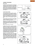
Remove the throttle lever and spring and file off the peened end of the throttle shaft until the lever can be removed.
Install the throttle spring and lever on the new carburetor with the self-tapping screw furnished. If dust seals are
furnished, install them under the return spring.
Idle Speed Adjustment Screw
Remove the screw assembly from the original carburetor and install it in the new carburetor. Turn it in until it contacts
the throttle lever. Then an additional 1-1/2 turns for a static setting.
Final Checks
Consult the service section under “Pre-sets and Adjustments” and follow the adjustment procedures before placing
the carburetor on the engine.
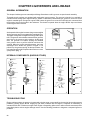
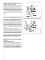
FLOAT TYPE CARBURETOR
DIAPHRAGM TYPE CARBURETOR
/
!/ 0
, !
,/ #
,
#
"( ! !0
.
(
,* " &
,*
.
#
"
**" & ,!
!/ 0
&
,*
"
.
, /
4
( ,/ #
,* " &
&
. ,/
#
,
#
/
,
,
,/ #
/
,/%
*
"(
(-%, $
, !
,/%
,/
, !
( ,/ #
4
, /
!/ 0
,
,* " &
4
.
0
,!
,/%
.
#%
"
.
!/
,
. , /
.
#%
#"
" &
,*
"
&
55 "&
,
( ! "* "
(
. ,*
(-%, $
, ! .
,* " & ! "*
#
,/
.
*/
&$
(
("
/"&/ ,* ( ( - % ,
$
, ! .
#
,/%
, !
(" */ &$ & ,0
#
(" */ &$ ! 4
#
'
.
/"&/ ,*
%
( '
'
.
.
,/
* "$
#"
" &
!
(" */ &$
4
,!
.
.
61
62
25
CHAPTER 4 GOVERNORS AND LINKAGE
GENERAL INFORMATION
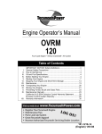
This chapter includes governor assembly and linkage illustrations to aid in governor or speed control assembly.
Tecumseh 4 cycle engines are equipped with mechanical type governors. The governor’s function is to maintain a
constant R.P.M. setting when engine loads are added or taken away. Mechanical type governors are driven off the
engine’s camshaft gear. Changes in engine R.P.M. cause the governor to move the solid link that is connected from
the governor lever to the throttle in the carburetor. The throttle is opened when the engine R.P.M. drops and closes
as the engine load is removed.
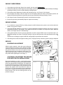
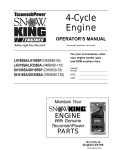
OPERATION
As the speed of the engine increases, the governor weights
(on the governor gear) move outward by centrifugal force.
The shape of the governor weights force the governor spool
to lift. The governor rod maintains contact with the governor
spool due to the governor spring tension. As the spool
rises, the governor rod rotates, causing the attached
outer governor lever to pull the solid link and close the
opening. When the engine speed decreases, the lower
centrifugal force allows the governor weights to be
pulled in by the governor spring. As the spool lowers, the
rod rotates and the solid link pushes the throttle to a more
open position (diag. 1).
1
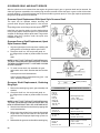
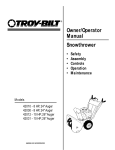
INTERNAL COMPONENTS (VARIOUS STYLES)
SPOOL
SHAFT
GEAR ASSY.
(GOV.)
WASHER
2
3
4
5
6
TROUBLESHOOTING
Engine problems where the governor is suspected to be the cause, may actually be the result of other engine system
problems. Hunting (engine R.P.M. surging up and down) indicates that the engine is incapable of maintaining a
constant R.P.M. with or without an engine load. Engine overspeeding (either with or without throttle movement) must
immediately before serious engine damage occurs. Use the following procedure to diagnose a suspected governor
problems.
26
ENGINE OVERSPEEDING
1. If the engine runs wide open (faster than normal), shut the engine immediately.
2. Check the condition of the external governor shaft, linkage, governor spring, and speed control assembly for breakage,
stretching or binding. Correct or replace binding or damaged parts.
3. Follow the governor adjustment procedure and reset the governor - see "Service" in this chapter.
4. Run the engine. Be ready to shut the engine off if an overspeed problem still exists. If the problem persists, the
engine will require disassembly to inspect the governor gear assembly for damage, binding, or wear.
5. See Chapter 9 under "Disassembly Procedure" to disassemble the engine.
6. Remove the governor gear assembly. Repair or replace as necessary.
ENGINE SURGING
1. Try to stabilize the engine R.P.M. by holding steady the solid link between the governor arm and the carburetor
throttle, using a pliers or fingers.
2. If the engine R.P.M. stabilizes, the governor or governor adjustment should be checked. See "Service" governor
adjustment procedure in this chapter. If the engine R.P.M. does not stabilize, the engine will require additional
checks, see Chapter 9 under "Troubleshooting".
3. If the problem persists after the governor adjustment, check the engine R.P.M. found on microfiche card # 30.
The R.P.M. settings are critical. If the R.P.M. setting for high and low speed are within specification and a slight
surge
is
experienced, increasing the engine idle R.P.M. setting slightly may eliminate this condition.
4. Check the governor shaft or linkages for binding, wear, or improper hookup. Check the governor spring for adequate
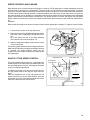
SERVICE
GOVERNOR ADJUSTMENT
With the engine stopped, loosen the screw holding the
governor clamp on the governor lever. Rotate the clamp
a direction that will force the throttle shaft open and allow
the governor follower arm to rest on the governor spool.
Push the governor lever connected to the throttle to the
wide open throttle position. Hold the lever and clamp in
this position while tightening the screw (diag. 7).
GOVERNOR ADJUSTMENT PROCEDURE
FOR SHORT BLOCK INSTALLATIONS
7
Short block installation on 3-5 h.p. vertical shaft engines
built prior to 1977 may require the governor clamp (tinnerman
style) to be repositioned to work properly. The clamp must
be removed from the governor rod and turned to the same
position as the original engine. Hook the solid link and
spring to the governor lever and position the clamp on
the governor rod. Follow the above governor adjustment
procedure to complete the short block governor set-up.
Units built after 1977 use the normal governor set up
procedure. (diag. 8)
!"
#$%% & "'
#$%% + ,)
& "' () "*
8
27
GOVERNOR GEAR AND SHAFT SERVICE
After the cylinder cover is removed from the engine, the governor spool, gear, or governor shaft can be removed. On
older style governor assemblies, the retaining ring must be removed to allow the spool or gear to slide off the shaft.
governor shafts (3 - 6.75 model engines) use an upset to hold the governor spool on. If the gear requires replacement,
the governor shaft will have to be removed.
Governor Spool Replacement With Upset Style Governor Shaft
The spool can be replaced without removing the
governor shaft. Grip the original spool in a vise and use
a
twisting
and pulling motion on the flange until the spool is free.
Install the new spool by starting it on the shaft and then
in the proper position. Place the spool on a solid surface
and push on the flange until the spool seats. The governor
weights must be in position under the spool after
installation. (diag. 9)
Governor Gear or Shaft Replacement, Upset
Style Governor Shaft
1. Grip the original spool in a vise and use a twisting and
pulling motion on the flange until the spool is free.
2. Clamp the shaft in a vise and pound gently on
the flange with a wooden or plastic mallet to remove
the
shaft.
9
NOTE: DO NOT TWIST THE SHAFT WHEN REMOVING.
THE SHAFT BOSS MAY BECOME ENLARGED, LEAVING
THE NEW GOVERNOR SHAFT LOOSE AND CAUSING
SEVERE DAMAGE.
3. To install a new shaft, first assemble the gear
and washer on the shaft. Start the shaft into the hole
with
a few taps from a soft faced hammer.
GEAR
SHIM
WASHER
SHAFT BOSS
a shim, part # 670297 just becomes snug [.010 - .020
(.254 - .508 mm) clearance].
670297 (modified)
Governor Shaft Replacement, Retaining
Ring Style
1. Remove the retaining ring, spool, gear assembly, and
washers.
2. Clamp the shaft in a vise and pound gently on
the flange with a wooden or plastic mallet to remove
the
shaft.
NOTE: DO NOT TWIST THE SHAFT WHEN REMOVING.
THE SHAFT BOSS MAY BECOME ENLARGED AND THE
NEW GOVERNOR SHAFT WILL BE LOOSE AND MOVE.
3. Start the new shaft into the shaft boss by tapping with
a soft faced hammer.
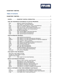
4. Refer to the chart at right for the proper shaft exposed
length. Add a drop of red Loctite 271 and press the
governor shaft to the proper depth using a press or a
11).
5. Reassemble the governor and install the retaining ring.
28
10
ENGINE MODEL
EXPOSED SHAFT LENGTH
ECH90
ECV100
H 30, 35
HS 40, 50
LAV 35
LEV (all)
OHH (all)
OVRM (all)
TNT 100, 120
TVS (all)
Mounting flange to Top
1.319 - 1.334"
(33.502 - 33.883 mm)
TVM (all)
V 50, 60, 70
VH 50, 60, 70
Mounting flange to Top
1.581 - 1.596"
(25.806 - 26.314 mm)
HH 100, 120
VH 100
Mounting flange to Top
1.016 - 1.036"
(25.806 - 26.314 mm)
H 50, 60, 70
HH 60, 70
HHM80
HM 70, 80, 100
Mounting flange to Shoulder
1.283 - 1.293"
(32.588 - 32.842 mm)
11
SPEED CONTROLS AND LINKAGE
Many different types of speed controls and linkage are used for O.E.M. applications. Linkage attachment points are
best recorded or marked prior to disassembly. This assures the correct placement during reassembly. On vertical
engines the solid link is always connected from the outermost hole in the governor lever to the throttle in the carburetor.
The link with the governor spring attached is connected between the control lever and the lower hole in the governor
Horizontal engines use one location (non-adjustable) speed control brackets. Most vertical engines use an adjustable
speed control bracket mounted above the carburetor. The ignition ground out switch, idle R.P.M. and high speed
R.P.M. adjustment screws are located on the speed control bracket. Some models use the idle R.P.M. adjustment on
the
carburetor.
Most vertical shaft engines must have the speed control bracket aligned when installing. To align the control bracket,
1. Loosen the two screws on the top of the panel.
-
2. Move the control lever to full wide open throttle position
and install a wire or aligning pin through the hole in
the
top of the panel, the hole in the choke actuating
lever, and the hole in the choke (diag. 12).
3. With the components aligned, tighten the two screws
on the control panel.
The following pages illustrate common linkage attachment.
Whenever the carburetor or the governor linkage is removed
or replaced, the engine R.P.M.'s should also be
system for the correct R.P.M. settings for the engine model
and specification.
SNAP IN "STYLE SPEED CONTROL"
This style of speed control is used on 3 - 6.75 model rotary
mower engines and is adjusted by two bendable tabs. Use
the speed adjustment tool (part # 670326) as illustrated
in diag.13 to adjust engine speed.
To adjust high speed, move the speed control lever to
the high speed position and align the high speed pin
holes.
Place the adjustment tool on the high speed tab and
speed control lever to the low speed position, place the
adjustment tool on the low speed tab and bend to either
increase or decrease to the correct speed.
12
LOW SPEED TAB
HIGH SPEED TAB
HIGH SPEED
PIN POSITION
DECREASE
INCREASE
TOOL 670326
13
29
ADJUSTING RPM ON MEDIUM FRAME
VERTICAL SPEED CONTROL
-
This speed control is adjusted by aligning the slot in the
speed control lever with the alignment hole on the mounting
bracket. Place a pin through the two holes, place
the equipment throttle control to the wide open position,
the bowden cable end in the control as shown, and tighten
the cable housing clamp. In this position, the gap of .040"
- .070" (1.016 - 1.778 mm) should exist at the gap location
as illustrated. This will assure that the carburetor will go
into full choke when the control is placed in the start
position.
./.
0 .%.
# .#1 0 # %%2 33
1%.4
14
ADJUSTING GOVERNED/NON-GOVERNED
With the engine running at its lowest speed, set the
governed idle at the designated RPM by adjusting the
governed idle screw or bending the idle tab. Next set the
non-governed idle by pushing the bottom of the governor
lever away from the control brackets so the throttle lever
contacts the idle speed crack screw (on the carburetor).
Hold the lever in this position and turn the crack screw to
600 RPM below the governed idle speed. This setting
prevents the throttle plate from closing off when going
from high speed RPM to low speed RPM. If improperly
adjusted,
the engine could experience an over lean condition.
The idle speed is adjusted by turning the idle speed screw
clockwise to increase engine R.P.M. and counter-clockwise
to decrease R.P.M. Use tool part # 670326 to adjust the
onto the adjustment tab and bend the tab to the left (toward
the spark plug end) to increase engine R.P.M. (diag. 14).
NOTE: Some engines use nylon bushings on the throttle
and choke linkage hook-up points to extend the life of the
linkage and to enhance the stability of the governor system.
Make sure they are in good condition and in place.
ADJUSTING RPM ON MEDIUM FRAME
VERTICAL
(up/down speed control)
To adjust the high speed RPM on Medium Frame Vertical
engines, move the control lever to the high speed
position (align high speed pin holes in the speed control
bracket). Place the slot on the straight end of tool
(number 670326) onto the high speed adjustment tab as
Rotate the bent end of the tool counterclockwise to
increase RPM and clockwise to decrease RPM. (diag.
15).
30
./. 0 .%. # .#1 0 # %%2 33
-
-
1%.4
15
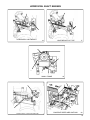
HORIZONTAL SHAFT ENGINES
-
-
HORIZONTAL LIGHTWEIGHT
16
LIGHTWEIGHT R.V. TYPE
17
-
6
6
SMALL FRAME
18
-
-
HORIZONTAL MEDIUM FRAME
19
CONSTANT SPEED APPLICATIONS
20
31
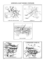
HORIZONTAL SHAFT ENGINES (CONTINUED)
-
IDLE SPEED
SCREW
MAIN MIXTURE
SCREW
IDLE MIXTURE
SCREW
6
HORIZONTAL MEDIUM FRAME
HMSK80-100
21
22
-
MEDIUM FRAME
23
TO INCREASE SPEED - CLOSE LOOP
TO DECREASE SPEED - SPREAD LOOP
7
6
SNOW KING ENGINES
32
24
SNOW KING ENGINES
25