1
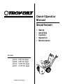
®
Owner/Operator
Manual
Snowthrower
•
•
•
•
•
Models
42010 - 8 HP, 24" Auger
42030 - 8 HP, 24" Auger
42012 - 10 HP, 26" Auger
42031 - 10 HP, 26" Auger
GARDEN WAY INCORPORATED
Safety
Assembly
Controls
Operation
Maintenance
Dear Owner:
Safety Alert Symbol
Thank you for purchasing this product. The unit
was carefully designed and manufactured to
provide excellent performance if properly
operated and maintained.
Read this manual. This is a safety, operation and
general maintenance manual which does not
attempt to cover major repairs. This manual is
considered a permanent part of the unit and it
must stay with the unit if it is resold. A
replacement manual can be obtained from the
factory. All information in this manual is based
on the latest product information available at the
time of printing. Review this manual frequently
to familiarize yourself with the unit, its features
and safe operation.
Our products have met the rigid
safety standards of the
Outdoor Power Equipment
Institute and an
independent testing laboratory.
IN
D
EL
OD
M
IE
IF
T
ER
C
P
G
RO
R
AM
BY
DE
PE
ND
SP
ON
EN
SO
RE
T
D
LA
BY
BO
RA
OUTDOOR POWER EQUIPMENT INSTITUTE
TO
RY
ANS B71.1-1986 SAFETY STANDARD
The warranty statement is included in the
literature package. Read it carefully. Also,
please complete and return the postpaid owner
registration card included with this manual. The
purpose of the card is to register each unit and
owner at the factory to provide information and
safety literature.
This is a safety alert symbol.
It is used in this manual and
on the unit to alert you to
potential hazards. When you see this
symbol, read and obey the message
that follows it. Failure to obey safety
messages could result in personal
injury or property damage.
Owner
Registration
Card
Please fill out and
mail the enclosed
MA I L
Owner Registration
Card. The purpose of this card is to
register each unit and owner at the
factory to provide information and
safety literature.
Warranty Service
The warranty statement is included in
your unit’s literature package.
Model/Serial Numbers
The model/serial numbers are located
on the back of the unit. For quick
reference, record these numbers in the
spaces below.
Date of Purchase:
______________________________
If you have any problems or questions
concerning the unit, contact your local
authorized dealer or the factory (our telephone
numbers and mailing address are listed on
page 3 and on the back of this manual).
We want to ensure your complete satisfaction at
all times.
WARNING:
The engine exhaust from
this product contains
chemicals known to the
State of California to cause
cancer, birth defects or other
reproductive harm.
2
Model/Serial Numbers:
______________________________
Left and Right Sides
Left and right sides of the unit are
determined from the operator position,
facing the direction of forward travel.
Customer Service
and Technical
Service
If you have questions
or problems with the
unit, contact your
authorized dealer or
call or write the factory. (When
calling or writing the factory, provide
the model/serial numbers of the unit.)
Replacement Parts
Factory specified
replacement parts are
available from either
your authorized dealer
or directly from the
factory. For parts ordering
information, refer to the parts catalog.
Table of Contents
SECTION 1: SAFETY .....................................................................
Safety Decals ............................................................................................................
SECTION 2: ASSEMBLY .................................................................
Install Wiring Harness/Adding Oil to the Engine/Check Gear Case Oil .......................
8
9
10
11
12
13
Check Tire Pressure/Install (optional) Drift Slicers ....................................................
13
SECTION 3: CONTROLS ..................................................................
Discharge Chute Controls/Ignition Keyswitch/Fuel Shut-Off Valve ...........................
14
14
14
Engine Throttle/Primer .............................................................................................
15
Engine Starter/Choke................................................................................................
15
15
Inspect Unit/Tools Required/Unpacking/Hardware Bag Contents ..............................
Install Handlebars......................................................................................................
Install Discharge Chute/Attach Chute Control Rod ....................................................
Attach Auger Drive Control Rod ................................................................................
Install Wheel/Gear Shift Control Rods .......................................................................
Wheel/Auger/Gear Shift Control Levers ....................................................................
Skid Shoes/Scraper Blade/Handlebar Warmer..........................................................
Engine Service and Repair
For engine service or
repair, contact your
nearest authorized
engine dealer. To
locate your nearest
engine dealer, look in the Yellow
Pages under “Engines–Gasoline.” The
engine on the unit is warranted by the
engine manufacturer. Any
unauthorized work performed on the
engine during the warranty period
may void the warranty. For complete
details on the engine warranty, refer to
the engine owner manual.
To Contact the Factory:
Garden Way Incorporated
1 Garden Way
Troy, New York 12180
Customer Service: 1-800-437-8686
Technical Service: 1-800-520-5520
Parts Service: 1-800-648-6776
FAX: (518) 391-7332
4
7
8
SECTION 4: OPERATION ................................................................
Transporting the Unit/Snowthrowing Patterns .........................................................
16
16
18
18
19
19
19
20
SECTION 5: MAINTENANCE ............................................................
21
Engine ......................................................................................................................
21
22
23
23
24
Pre-Operation Checklist............................................................................................
Starting the Engine ...................................................................................................
Stopping the Engine .................................................................................................
Auger Drive Engagement/Disengagement ................................................................
Wheel Drive Engagement/Disengagement ................................................................
Shifting Gears...........................................................................................................
Lubrication ...............................................................................................................
Wheel Drive ..............................................................................................................
Shear Bolts ...............................................................................................................
Auger Drive ..............................................................................................................
Slip Differential ........................................................................................................
Gear Shift Rod ..........................................................................................................
Drive Disk Clearance.................................................................................................
Brake Arm Adjustment .............................................................................................
Skid Shoes/Scraper Blade ........................................................................................
Off-Season Storage ..................................................................................................
Troubleshooting Chart..............................................................................................
Maintenance Schedule.............................................................................................
Outside the U.S.A. and Canada:
Specifications ...........................................................................................................
Customer Service: (518) 391-7007
Technical Service: (518) 391-7008
Parts Service: (518) 391-7006
FAX: (518) 391-7332
Wiring Diagram ........................................................................................................
25
25
25
26
26
26
27
29
30
31
3
Section
1 Safety
SPARK ARRESTER WARNING TO
RESIDENTS OF CALIFORNIA AND
SEVERAL OTHER STATES
Under California law, and under the
laws of several other states, you are
not permitted to operate an internal
combustion engine using
hydrocarbon fuels on any forest,
brush, hay, grain, or grass covered
land; or land covered by any flammable agricultural crop without an engine spark arrester in continuous effective
working order.
The engine on the unit is an internal combustion engine which burns gasoline, a hydrocarbon fuel, and must be
equipped with a spark arrester muffler in continuous effective working order. The spark arrester must be attached to the
engine exhaust system in such a manner that flames or heat from the system will not ignite flammable material. Failure
of the owner/operator of the unit to comply with this regulation is a misdemeanor under California law (and other states)
and may also be a violation of other state and/or federal regulations, laws, ordinances or codes. Contact your local fire
marshal or forest service for specific information about which regulations apply in your area.
Training
1.
2.
Read this owner/operator manual and
the separate engine owner manual
carefully before operating the unit. Be
completely familiar with the controls
and the proper use of the unit. A
replacement manual is available by
contacting the factory.
Never allow children or untrained
adults to use the unit.
3.
Keep the area of operation clear of all
people, particularly small children and
pets. Keep bystanders at least 25 feet
away from the area of operation.
4.
Familiarize yourself with all of the
safety and operating decals on the
unit and on any attachments or
accessories.
5.
Do not run the engine in an enclosed
area. Engine exhaust contains carbon
monoxide gas, a deadly poison that is
odorless, colorless, and tasteless. Do
not operate the unit near buildings,
windows, or air conditioners.
6.
7.
4
Keep hands or any other part of the
body or clothing away from the inside
of the auger housing, discharge
opening, or moving parts.
Before inspecting, servicing or
adjusting any part of the unit, shut the
engine off, wait for all moving parts to
stop, and disconnect the spark plug
wire from the spark plug. Secure the
wire away from the spark plug.
8.
Do not operate the unit if you are
under the influence of alcohol,
medication, or when tired or ill.
Preparation
1.
Wear approved safety glasses or eye
shields and hearing protection when
operating the unit. The operation of
any powered machine can result in
foreign objects being thrown by highspeed rotating parts.
2.
Do not wear loose-fitting clothing,
such as scarves, which could be
caught by moving parts. Tie up or
restrain long hair.
Section 1: Safety
3.
4.
5.
Before starting the engine, check the
tightness of all screws, nuts, bolts,
and other fasteners. Replace or clean
any damaged or unreadable safety
and operating labels.
6.
a.
Wear adequate winter outer garments
when operating the unit. Wear
footwear that will improve footing on
slippery surfaces. Exercise caution to
avoid slipping or falling, especially
when operating in reverse.
Use extra care when handling
gasoline and other fuels. Gasoline
and its vapors are highly flammable
and explosive. To help prevent a fire
or explosion:
a.
Store gasoline only in an
approved gasoline storage
container, safely out of the reach
of children.
b.
Never remove the fuel fill cap on
the fuel tank, or add fuel while
the engine is running or hot.
c.
Keep matches, smoking
materials, open flames, and
sparks away from the fuel tank
and gasoline storage container.
d.
e.
f.
g.
Fill the fuel tank outdoors and
with extreme care. Never fill the
fuel tank indoors.
Replace the fuel fill cap on the
fuel tank, the cap on the gasoline
storage container, and clean up
fuel spills before starting the
engine.
Leave 1/2-inch (2.5 cm) of air
space at the top of the fuel tank
to allow for fuel expansion.
Do not store the unit or the
gasoline storage container where
there is a danger of an open
flame or spark, or where ignition
sources are present such as hot
water and space heaters,
furnaces, clothes dryers, stoves,
electric motors, etc.
For units equipped with the electricstart kit:
b.
Only plug into a properly
grounded, 3-pronged outlet. Do
not use any adapters on the cord.
c.
Inspect the electrical cord for
damage before use. If it is
damaged, do not use it.
d.
Stand on dry ground when
handling the electrical cord. Do
not handle the electrical cord
with wet hands or wet gloves.
Do not use the electric starter if it
is raining.
e.
f.
7.
Only use a 3-pronged, UL rated
and approved, outdoor use
electrical cord.
Connect the cord to the electric
starter first, and then plug the
cord into a properly grounded
outlet (this lessens the chances
of sparks from occurring near the
engine).
Do not abuse the electrical cord.
Do not pull the unit by the cord.
Do not pull the cord to disconnect
it from the outlet. Keep the cord
away from sharp edges, oil, and
excessive heat.
Adjust the skid shoes and scraper
blade so the auger housing clears
gravel or crushed rock surfaces.
Operation
1.
The operator of the unit is responsible
for the safety of all persons in the
operating zone of the unit.
2.
Before starting the unit, disconnect
the spark plug wire and check the
auger and discharge chute to make
sure they are free of ice. Check the
engine oil level. Reconnect the spark
plug wire before starting the engine.
3.
Disengage all clutches and shift into
neutral before starting the engine.
4.
Let the unit adjust to outdoor
temperature before use.
5.
Check the operation of the controls
before using the unit. Do not operate
the unit unless all controls are
operating properly.
6.
Never carry passengers on the unit.
They could fall off and be seriously
injured, or they could interfere with
safe operation.
7.
Keep hands, other body parts, and
clothing away from any moving or
rotating parts. Keep clear of the intake
and discharge openings at all times.
8.
Before starting the engine, inspect the
area where the unit is to be used and
remove all sleds, boards, doormats,
metal, bottles, cans, or other debris.
9.
Keep children out of the area of
operation and under the watchful eye
of an adult not operating the unit.
Never assume that children will
remain where you last saw them.
10. If the unit makes an unusual noise or
vibration, immediately shut the engine
off, wait for all moving parts to stop,
disconnect the spark plug wire from
the spark plug and perform the
following steps:
a.
Inspect for damage.
b.
Replace or repair any damaged
parts.
c.
Check for and tighten any loose
parts.
5
Section 1: Safety
11. Before inspecting the unit or making
any adjustments, or if the unit jams or
becomes clogged, shut the engine off
immediately and allow all moving
parts to come to a stop. Disconnect
the spark plug wire from the spark
plug and secure the wire away from
the spark plug. Use only a wooden
stick (at least 3 feet long) to clear
away any blockage.
22. Remove any hearing protection and
watch for traffic when operating near,
or when crossing roadways.
32. Disengage the auger and wheel drives
if you are approached by any child,
inattentive person or pet.
23. Do not leave the unit unattended with
the engine running. Stop the engine,
let all moving parts come to a stop,
and disconnect the spark plug wire
from the spark plug before leaving
the unit.
33. Run the unit for a few minutes after
use to prevent freeze-up. Remove any
snow from the unit (snow can melt,
re-freeze, and jam the unit).
12. Keep all guards, covers, shields and
safety devices in place and in good
working condition. Do not attempt to
defeat the purpose of any safety
device.
24. Use only attachments and accessories
that are approved for use with the
unit. Contact the factory customer
service department, at the address
and phone number on page 3, if you
are not sure about the use of any
attachment or accessory.
1. When the unit is stopped for servicing,
inspection, storage, or to change an
attachment or an accessory,
disconnect the spark plug wire from
the spark plug and secure the wire
away from the plug. Let the engine
cool before making inspections,
adjustments, or performing any
maintenance.
13. Exercise extreme caution on slopes.
14. Do not attempt to clear steep slopes.
15. Do not clear snow across the face of
slopes. Exercise extreme caution
when changing direction on slopes.
16. Always observe the terrain. Watch for
and avoid obstacles. Stay away from
holes, ditches, soft or steep
embankments and other potentially
dangerous terrain. Deep snow can
hide obstacles and drop-offs.
17. Do not use the unit near drop-offs,
ditches, or embankments. If a wheel
goes over an edge, or if an edge
caves in, the unit could overturn.
18. Do not operate the unit at high
transport speeds on slippery
surfaces. Wet surfaces reduce
traction and stability.
25. Operate the unit only in daylight or in
good artificial light.
26. Do not tamper with the engine
governor settings. The governor
controls the maximum safe engine
operating speed and protects the
engine and moving parts from
damage. Contact your local engine
dealer for service if a problem exists.
27. Shut off the engine, disconnect the
spark plug wire and secure the wire
away from the spark plug, before
transporting the unit in a vehicle.
28. Do not touch the muffler or other
engine parts which may be hot from
operation. Wait for parts to cool
completely before inspecting,
cleaning, or repairing the unit.
19. Look behind and use care when
operating the unit in reverse. If you
have to pull the unit backward,
disengage the auger and wheel drives.
Always check behind you for hazards.
29. Never operate the unit near buildings,
glass enclosures, automobiles,
window wells, drop-offs, etc., without
first properly adjusting the discharge
angle and direction. Keep children and
pets away.
20. Be extremely careful when using the
unit near blind corners, shrubs, trees,
and other objects that may obscure
vision.
30. Never direct discharge at persons,
animals, vehicles or buildings. Never
allow anyone in front of the unit when
the engine is running.
21. Be extremely careful when operating
near or crossing gravel drives, walks
or roads. Stay alert for hidden
hazards or traffic.
31. Disengage the auger drive when the
unit is being transported or is not
in use.
6
Maintenance and Storage
2. Maintain the unit and all attachments
and accessories in safe working
condition.
3. Never perform any maintenance while
the engine is running, or when the
spark plug wire is connected to the
spark plug.
4. Do not store the unit or fuel container
inside an enclosure where there is an
open flame or spark, or where ignition
sources are present, such as: hot
water and space heaters, furnaces,
clothes dryers, stoves, electric
motors, etc.
Section 1: Safety
Safety Decals
5. Allow the engine to cool before storing
in any enclosure.
6. Store gasoline in a cool, wellventilated area, safely away from any
spark- or flame-producing equipment.
For your personal safety and the
safety of others, a number of safety
message decals have been affixed to your
unit. Keep them clean and legible at all
times. Contact your local service dealer or
the factory for replacements if any decals
are damaged or missing.
Refer to the separate parts catalog for
decal locations, part numbers, and
ordering instructions.
7. Store gasoline only in an approved
gasoline storage container, safely out
of the reach of children.
8. Use only original equipment
replacement parts. Parts manufactured
by others could present a safety
hazard even though they may fit on
the unit.
9. Store the unit where children will not
have access to it. Always disconnect
the spark plug wire from the spark
plug to prevent accidental starting.
Remove the ignition key from the
ignition keyswitch.
10. Check the tightness of the auger shear
bolts and other fasteners at frequent
intervals. Torque shear bolts to 11 ft.
lbs. (15 Nm).
11. Maintain or replace safety and
instruction decals as needed if they are
damaged or illegible. Refer to the parts
catalog for decal location and ordering
information.
12. Refer to the engine owner manual for
complete engine information.
7
Section
2 Assembly
IMPORTANT: Follow the assembly steps
carefully. Contact the factory or your
local authorized dealer if you have any
questions or problems.
A. Inspect Unit
Inspect the unit and shipping crate for
damage immediately after delivery.
Contact the carrier (trucking company) if
you find or suspect damage. Inform them
of the damage and request instructions
for filing a claim. To protect your rights,
put your claim in writing and mail a copy
to the carrier within 15 days after the unit
has been delivered. Contact the factory as
indicated on page 3 of this manual if you
need assistance.
B. Tools/Materials Required for
Assembly
(1) Crowbar or large screwdriver (to
disassemble wood crate)
(1) Scissors or knife (to cut plastic ties)
(1) *5/16" wrench
(1) *3/8" wrench
(2) *7/16" wrenches
(2) *1/2" wrenches
(1) *9/16" wrench
(1) Phillips head screwdriver (medium)
(1) Needle-nosed pliers (medium)
(1) Automotive-type tire pressure gauge
(1) Funnel
(1) Clean, high-quality motor oil. Refer to
the separate engine owner’s manual
for the exact oil specifications and
amount needed for your engine.
C. Unpacking Instructions
D. Hardware Bag Contents
The shipping crate should contain:
The hardware bag should contain the items
listed below and shown in Fig. 2-2:
• Snowthrower/engine/auger assembly
• Handlebar assembly
• Discharge chute assembly
1. Remove top and sides of wood crate.
2. Remove discharge chute assembly
(with attached hardware bag) from
inside cardboard sleeve. Remove
cardboard sleeve.
3. Remove the hex nut (A, Fig. 2-1) and
the shipping strap from the left side
skid shoe. Reinstall the hex nut,
tightening it securely.
4. Remove the screw (B, Fig. 2-1) and the
shipping strap from the rear cover on
the right side of the unit. Reinstall the
screw, tightening it securely.
5. The unit is heavy. Use caution and
obtain the help of at least one
assistant. Carefully remove the unit
from the crate by rolling the unit off the
platform. Park the unit on a clean, level
surface.
Ref.
A
B
C
D
E
F
G
H
I
J
--
Description
Qty.
Cable tie ......................................
Hex hd. flange screw, 3/8-16 x 3/4
Hex hd. screw, 1/4-20 x 3/4...........
Locknut, 1/4-20 .............................
Phillips hd. screw, #10-24 x 3/8 ...
Locknut, #10-24 ............................
Cotter pin ......................................
*Shear bolt, 5/16-18 x 1-3/4 .........
*Locknut, 5/16-18 .........................
Ignition key....................................
Grease Tube (not illustrated). For
maintenance use if required.........
*These items are extra auger shear bolts
and locknuts (if the auger catches a hard
obstruction, the shear bolts are designed
to break to prevent damage to the auger
and other parts). See the “Maintenance”
section for replacement steps.
* Adjustable wrenches may be used.
IMPORTANT: Motor oil must be added to
the engine crankcase before the engine
is started. Follow the instructions in this
“Assembly” section.
B
A
Fig. 2-1
8
Remove Rear Shipping Strap.
3
4
2
2
2
2
1
2
2
2
1
Section 2: Assembly
IMPORTANT: Left and right sides of the
unit are determined from the operator
position, facing the direction of forward
travel.
J
A
E. Install Handlebars
1. Cut the plastic cable ties securing the
handlebar ends to the chassis and
remove the handlebars. Remove the
protective wrapping on the handlebars.
2. Attach the handlebars to the sides of
the chassis as follows (use the four
3/8-16 x 3/4" hex flange screws
supplied in hardware bag):
H
Hardware shown full size.
B
C
E
a. Install two screws in the upper
mounting holes (C, Fig. 2-3) on
each side. Leave screws loose
enough to allow handlebar to pivot.
b. Install two screws (D) in the lower
mounting holes.
c. Using light pressure, press down on
the left side handlebar and tighten
the two screws. Repeat on the right
side handlebar.
G
F
D
I
Fig. 2-2
3. There are four pre-installed screws
(E, Fig. 2-3) on the inside of the
handlebars that secure the control
panel to the handlebars. Check each
screw and tighten securely.
E
E
C
D
Fig. 2-3
9
Section 2: Assembly
F. Install Discharge Chute
1. Remove the cardboard packing shield
from the discharge chute mount
opening.
2. Loosen (do not remove) the left and
right side sets of plastic shims (G, Fig.
2-4, inset A) and plastic hold-down
clips (H, Fig. 2-4, inset A) on the
toothed flange (J) of the discharge
chute assembly. Remove and save the
remaining (front) hold-down clip, shim
and mounting hardware.
3. From either side of the unit, slide the
discharge chute onto the chute
mounting flange (K), making sure that
the plastic shims (G) are above the
flange and the plastic hold-down clips
(H) are below the flange. Tighten the
shim mounting hardware securely (if
necessary, rotate the discharge chute
to the right in order to tighten the left
side shim and hold-down clip).
4. Hook the front hold-down clip (H)
under the mounting flange (K) and
place the front plastic shim (G) on top
of the hold-down clip, between the top
of the flange and the toothed chute
flange. Using two 5/16" wrenches,
secure with the screws, washers and
locknuts.
5. Remove the plastic cable tie that
secures the worm gear assembly
(L, Fig. 2-4 inset B) to the
mounting bracket.
6. Remove the washer and locknut from
the screw (M, Fig. 2-4 inset B) in the
worm gear assembly (L). Position the
worm gear assembly on the mounting
bracket as follows:
a. Engage the worm gear threads 1/2way with the teeth on the flange of
the discharge chute base (rotate
chute as needed).
b. The length of the worm gear should
be centered with the teeth on the
flange of the discharge chute base.
c. Reinstall the washer and locknut on
the screw (M) and tighten securely.
10
A
B
J
G
M
L
H
K
J
(Front shim) G
F
K
(Front holddown clip) H
Fig. 2-4
G. Attach Chute Control Rod
O
P
N
Fig. 2-5
d. Turn chute control rod (F, Fig. 2-4)
by hand to be sure the worm gear
and discharge chute rotate freely,
but with enough resistance to
prevent free rotation of the
discharge chute during snow
removal operation. Readjust
position of worm gear assembly as
necessary.
7. Insert the flexible fingers on the plastic
snow deflector (N, Fig. 2-5) inside the
chute deflector cap (O). Close the
deflector cap by pulling the lever (P)
outward and moving the deflector cap
down. Release the lever to secure the
deflector cap in one of the discharge
angle selector holes.
1. Remove the plastic cable tie that
secures the auger drive control rod
(AA, Fig. 2-6) to the right handlebar.
Next, remove the plastic cable tie that
secures the chute crank rod (short rod
with plastic swivel blocks) to the auger
drive control rod.
2. Pull the chute crank rod (Z, Fig. 2-6)
up through the top of the control
panel.
3. Attach the chute control rod sections
(S and U, Fig. 2-6) as follows:
a. Insert the angled end of the chute
control rod, (U, Fig. 2-6 inset) into
the hole in the swivel block (V) that
is attached to the end of the chute
crank rod (S).
b. Insert a cotter pin (W) through the
hole in the chute control rod (U) and
spread the ends of the cotter pin.
4. Position the chute control support (Y,
Fig. 2-7) against the underside of the
handlebar console as shown. Secure
the support with the two #10–24 x 3/8"
Phillips pan head screws and #10–24
locknuts supplied.
Section 2: Assembly
X
Z
T
AA
S
Fig. 2-7
Y
5. Rotate the chute control crank (Z, Fig.
2-6). The deflector chute should turn
freely. Adjust the worm gear assembly
bracket (L, Fig. 2-4) as necessary to
prevent binding.
S
V
W
U
H. Attach Auger Drive Control Rod
U
R
Fig. 2-6
AF
AE
AA
R
AT
AS
AC
AD
AB
AG
Fig. 2-8
1. Remove the plastic cable tie that
secures the auger drive control arm
(AD, Fig. 2-8) to the transmission shift
arm (AB).
2. The auger drive control rod (AA, Fig.
2-8) has been pre-adjusted at the
factory. To avoid misadjustment, do
not rotate the jam nut (AT, Fig. 2-8)
while completing the following steps.
3. Hold the jam nut (AT) in place with a
7/16" wrench and use another 7/16"
wrench to thread the adjusting thimble
(AS) downward a total of 12 turns.
4. Raise auger drive control handle (X,
Fig. 2-6) all the way up. Then hook the
spring (AC, Fig. 2-8) at the lower end
of the auger drive control rod (AA) into
the hole in the auger drive control arm
(AD).
5. Thread the adjusting thimble (AS, Fig.
2-8) upward until it contacts the jam
nut (AT). Using two wrenches, tighten
the jam nut against the adjusting
thimble. When the engine is started,
as described in the “Operation”
section, you will be given a functional
check to make sure the auger drive
control rod is properly adjusted.
AH
11
Section 2: Assembly
I. Attach Wheel Drive Control Rod
1. Remove the plastic cable tie that
secures the wheel drive control rod
(AE, Fig. 2-8) and the gear shift
control rod (AF) to the left handlebar.
2. Hook the spring (AG, Fig. 2-8) at the
lower end of the wheel drive control
rod (AE) into the hole in the wheel
drive control arm (AH). If necessary,
raise the wheel drive control arm (AH)
while attaching the spring.
AF
3. The wheel drive control rod has been
pre-adjusted at the factory. When the
engine is started, as described in the
“Operation” section, you will be given
a functional check to make sure the
wheel drive control rod is properly
adjusted.
AB
Fig. 2-9
J. Install Gear Shift Control Rod
1. Place the gear shift select lever (T, Fig.
2-6) in the No. 5 position.
Yellow
2. Gently push the transmission shift arm
(AB, Fig. 2-9) fully downward.
AO
AM
3. Align the holes in the transmission
shift arm (AB) and the lower end of the
gear shift control rod (AF). If the
holes do not align, follow the “Gear
Shift Rod Adjustment” procedure in
the “Maintenance” section of this
manual.
AL
AN
Yellow &
Red Wires
4. Attach the gear shift control rod (AF)
to the transmission shift arm (AB) with
the two 1/4-20 x 3/4 hex head screws
and 1/4-20 locknuts supplied (see
Fig. 2-9).
Black
AK
Black
Red
Blue
Fig. 2-10
12
Section 2: Assembly
K. Wiring Harness Installation
L. Add Engine Oil to Crankcase
1. Remove the plastic cable tie that
secures the wiring harness to the right
handlebar.
2. Route the wiring harness to the inside
of the right handlebar and over to the
right side of the engine.
3. Attach the ring terminal (AK, Fig. 2-10)
on the two black wires to the screw on
the engine shroud as shown. The
lockwasher should be next to the
screw head and the ring terminal in
between the lockwasher and the
engine shroud.
4. Connect the spade terminal (AL, Fig.
2-10) on the black wire to the yellow
wire receptacle inside the connector
receptacle (AM). Note that there are
two yellow wires extending out of the
back of the receptacle (AM).
Do not install the spade terminal (AL)
into the receptacle for the yellow wire
that is attached with a small plastic
connector to the red wire.
5. Plug the wiring harness connector
(AN) into the engine connecting plug
(AO). Note that it can only be plugged
in one way.
WARNING
DO NOT START ENGINE UNTIL ENGINE
CRANKCASE HAS BEEN FILLED WITH
OIL. FAILURE TO FOLLOW THIS
INSTRUCTION WILL RESULT IN SERIOUS
ENGINE DAMAGE.
M. Check Auger Gear Case Oil
Level
The auger gear case was filled at the
factory with the correct amount of SAE 90
gear oil. This level should be checked
before using the unit. Refer to
“Lubrication” in the Maintenance section
of this manual for complete information.
N. Check Tire Pressure
1. Be sure that the engine is level before
checking or adding oil.
2. To add engine oil, unscrew dipstick
(AP, Fig. 2-11). Fill oil at the dipstick
opening with fresh oil. See the engine
owner manual for correct oil specifications and quantity required. Do not
use SAE 10W40.
3. Oil level on dipstick should always be
above “ADD” and below “FULL”. Wait
a few minutes after filling crankcase,
allowing oil to settle. Insert dipstick
and tighten securely. Recheck level
and adjust as necessary.
Check the air pressure in both tires using
an automotive-type tire pressure gauge.
Inflate tires evenly to 8-12 psi (55-82 kPa).
O. Install Drift Slicers (optional
attachment)
The optional drift slicers (AR, Fig. 2-12)
are designed for use in deep snow
conditions. To install the drift slicers:
1. Position the drift slicers (AR, Fig. 2-12)
to the outside of the auger housing.
2. Attach the drift slicers with the four
5/16–18 x 3/4 screws and locknuts
(AS) provided with the drift slicers.
AP
AS
6. Using two of the plastic cable ties
provided, loosely (to avoid stretching
wires) attach the upper section of the
wiring harness to the right handlebar.
Use the third cable tie to loosely tie the
black, blue and red wires together at
the side of the engine. Be sure that the
wires are positioned safely away from
the wheel.
AR
AS
Fig. 2-11
Fig. 2-12
13
Section
3 Controls
This section defines the various controls
on the unit. Refer to the following section,
“Operation,” for an explanation of the
proper use of these controls.
A, Fig. 3-1—Wheel drive control
lever
Controls the engagement of the wheel
drive. When this lever is down against the
handlebar and the engine is running, the
wheels will rotate. Refer to the
“Maintenance” section of this manual for
the proper adjustment information.
B, Fig. 3-1—Auger drive control
lever
Controls the engagement of the auger
drive. When this lever is down against the
handlebar and the engine is running, the
auger will rotate. Refer to the
“Maintenance” section of this manual for
the proper adjustment information.
C, Fig. 3-1—Gear shift control
lever
Controls the selection of travel speeds:
five forward and two reverse positions.
Refer to the “Maintenance” section of this
manual for the proper adjustment
information.
D, Fig. 3-1—Discharge chute
control rod
Controls the direction the discharge chute
is facing. Rotate this crank clockwise to
turn the discharge to the right; rotate
counter-clockwise to turn the discharge
chute to the left. Approximately ten turns
of this crank will move the discharge chute
all the way from one side to the other.
G, Fig. 3-1—Ignition keyswitch
The keyswitch has two positions: “ ”
RUN and STOP. Rotating the key to the
“ ” RUN position allows the engine to be
started. Rotating the key to the STOP
position stops the engine. Always remove
the ignition key when the unit is not in
use. Store the key in a safe place out of
the reach of children.
Fig. 3-3—Fuel shut-off valve
Located beneath the fuel tank, the fuel shutoff valve (Fig. 3-3) controls fuel flow from
the fuel tank to the carburetor. Refer to the
engine owner manual for complete
information.
E & F, Fig. 3-2—Discharge chute
deflector cap and lever
Controls the vertical angle of the snow
discharge. To adjust the discharge angle:
move the discharge cap by pulling lever
(F, Fig. 3-2) outward and moving the
discharge deflector cap up or down. The
discharge chute deflector cap should
usually be adjusted to a low angle,
especially in windy conditions.
E
A
F
C
ON
G
B
OFF
D
Fig. 3-1
14
Fig. 3-2
Fig. 3-3
Section 3: Controls
H, Fig. 3-4—Throttle
L, Fig. 3-4—Choke knob
Handlebar Warmer Feature
Located on back left corner of the engine,
the throttle controls the speed of the
engine. For proper operation information,
refer to the following section, “Operation.”
Controls the amount of gasoline in the
air/gasoline mixture that is fed into the
engine. This is known as “choking” the
engine. It is often necessary to “choke” a
cold engine when starting. Refer to the
following section, “Operation,” for proper
operation information.
The unit is equipped with handlebar
warmers that are automatically activated
when the engine is running. Allow a few
minutes (perhaps longer in extremely cold
temperatures) for the handlebars to warm
to the touch.
NOTE: The engine lubrication and
cooling systems operate best at full
throttle. Operating the engine at less
than full throttle for extended periods
can adversely affect the performance of
this system.
J, Fig. 3-4—Primer button
Located at the back upper left corner of
the engine. Pressing the primer button
pumps small amounts of gasoline into the
engine to improve cold weather starting.
Refer to the following section,
“Operation,” for proper operation
information.
K, Fig. 3-4—Recoil starter
Located on the back of the engine, the
engine recoil starter is used to pull-start
the engine. Refer to the following section,
“Operation” for proper operation
information.
J
M, Fig. 3-5—Skid shoes
Controls the distance between the auger
housing/scraper blade and the ground.
This distance should be adjusted to clear
any uneven or gravel surfaces. Refer to
the “Maintenance” section for proper
adjustment information.
N, Fig. 3-5—Scraper blade
Located at lower front bottom edge of the
auger housing, the scraper blade is
designed to contact the ground and to
clear snow down to the pavement. Refer
to the “Maintenance” section for proper
adjustment information.
K
L
N
H
M
Fig. 3-4
Fig. 3-5
15
Section
4 Operation
Pre-operation checklist
O
1. Review Section 1, “Safety” and
Section 3, “Controls” in this manual.
A
J
2. Check the unit for any loose or
missing hardware. Tighten or replace
as needed.
3. Check inside the auger housing and
the discharge chute and remove any
debris.
4. Check the engine oil level:
a. Move the unit onto a level surface.
K
b. Remove the engine oil dipstick (O,
Fig. 4-1).
c. Wipe the oil from the dipstick with a
clean cloth.
d. Screw the dipstick back into the
engine.
Fig. 4-1
e. Remove the engine oil dipstick (O ,
Fig. 4-1) again.
f. The oil level should be between the
“FULL” and the “ADD” marks on the
dipstick. Refer to the engine owner
manual for proper engine oil specifications.
WARNING
DO NOT START ENGINE UNTIL ENGINE
CRANKCASE HAS BEEN FILLED WITH
OIL. FAILURE TO FOLLOW THIS
INSTRUCTION WILL RESULT IN SERIOUS
ENGINE DAMAGE.
5. Remove the gasoline tank fill cap (A)
and check the level of gasoline in the
gasoline tank.
N
M
Z
Fig. 4-2
16
Z
M
Section 4: Operation
WARNING
H
P
L
B
GASOLINE IS HIGHLY FLAMMABLE AND
ITS VAPORS ARE EXPLOSIVE. NEVER
REMOVE THE GASOLINE TANK FILL CAP
OR ADD FUEL WHEN INDOORS OR
WHEN ENGINE IS RUNNING OR HOT.
WIPE UP SPILLED GASOLINE
IMMEDIATELY. KEEP SMOKING
MATERIALS, SPARKS OR FLAMES FAR
FROM FUEL TANK AND CONTAINERS.
AA
Fill the fuel tank with fresh, clean
unleaded gasoline with a minimum
octane rating of 87. Leave 1/2" of
space for fuel expansion. DO NOT
MIX OIL WITH GASOLINE! Tighten
the gasoline fill cap securely. Refer to
the engine owner manual for additional
gasoline information.
DO NOT MIX OIL WITH GASOLINE!
Fig. 4-3
6. The unit should be adjusted so the
auger housing and the scraper blade
(N, Fig. 4-2) are 1/8" above the surface
to be cleared. If the unit is used to
clear gravel or uneven surfaces, this
adjustment should be increased so
gravel or other foreign objects are not
scooped up into the auger.
To adjust the auger housing/scraper
blade height:
a. Move the unit onto a level surface.
b. Loosen the bolts securing the skid
shoes (M, Fig. 4-2).
c. Adjust the skid shoes (M) until they
are in the correct position to support
the auger housing and the scraper
blade (adjust both skid shoes the
same to prevent uneven snow
removal).
d. Tighten the bolts to lock the skid
shoes (M) into the proper position.
7. The scraper blade (N, Fig. 4-2) can
also be adjusted. Adjust the scraper
blade (N) at the carriage bolts
(Z, Fig. 4-2). Adjust the bottom edge
of the scraper blade so it is parallel to
the bottom edge of the auger.
8. Adjust the discharge chute deflector
cap (AA, Fig. 4-3) with lever to the
desired angle of discharge. Usually
keep the angle of the discharge
defector cap low, especially in
windy conditions.
9. Rotate the discharge chute control rod
(crank) (P, Fig. 4-3) and check for
binding.
12. Spray silicone spray on the inside of
the deflector chute, the chute
discharge deflector cap, the auger
housing, and on the augers. This will
help prevent snow from sticking (do
not spray silicon spray on rubber or
plastic: damage can result).
13. Re-connect the spark plug wire
(J, Fig. 4-1) to the spark plug if
needed.
14. Rotate the fuel shut-off valve
(K, Fig. 4-1) to the “ON” position,
if so equipped.
10. Check the auger drive and wheel drive
control levers (H and L, Fig. 4-3) for
freedom of movement.
11. Check the tire pressure. Inflate both
tires evenly to 8 to 12 PSI (55 to
82 Kpa).
17
Section 4: Operation
H
P
B
Starting the engine
L
C
1. Review the “Pre-operation checklist”
earlier in this section. Move the unit
outside to a well-ventilated, level area.
2. Move the gearshift lever (B, Fig. 4-4)
into the desired gear position.
3. Turn the ignition key (C, Fig. 4-4) to the
RUN “ ” position.
4. Turn choke knob “ ” (D, Fig. 4-5)
clockwise to FULL CHOKE (warm
engines require little or no choking).
Push the primer button (E, Fig. 4-5)
two or three times (cover hole in
center of bulb when pushing). If the
temperature is below 15° F (-9° C),
push the button 4 or 5 times.
5. Move the throttle lever (F) to FAST
.
To start engine with the recoil starter:
6. Before using the recoil starter
(G, Fig. 4-5), make sure there are
no obstacles behind you.
7. Pull recoil starter handle rapidly to
overcome engine compression,
prevent kick-back and start engine.
Maintain control of rope so it slowly
returns into the starter mechanism.
Repeat pulling actions until engine
starts.
8. Turn the choke knob “ ” (D, Fig. 4-5)
counterclockwise out of the full-choke
position. Turn the choke off as the
engine warms up.
WARNING
Fig. 4-4
8. Push the starter button on the switch
box. When the engine starts, release
the button.
NOTE: The starter is thermally protected.
When overheated from continuous use,
the starter will stop functioning. Allow
the starter to cool for several minutes
before attempting to restart engine.
9. Move the choke knob “ ” (D, Fig. 45) out of the full-choke position. Turn
the choke off as the engine warms up.
Stopping
DO NOT USE THE 110V ELECTRIC
STARTER DURING RAINY WEATHER. DO
NOT STAND IN WATER OR ON DAMP
SURFACES WHEN CONNECTING CORD.
Emergency conditions:
For the optional electric starter:
6. Plug the electrical cord into the
electric start switch box on the engine.
Normal conditions:
7. Plug the other end of the electrical
cord into a properly grounded 3pronged 110V outlet.
18
2. Move the throttle lever (F, Fig. 4-5)
into the “ ” position. Allow the
engine to idle for several minutes to
melt any snow on the engine.
3. Rotate the ignition key (C, Fig. 4-4)
into the “STOP” position. Remove the
key.
4. Disconnect the spark plug wire (J, Fig.
4-5) from the spark plug.
5. To prevent the unit from freezing-up:
a. Remove standing water from the
floor of the auger housing.
1. Release both control levers (H and L,
Fig. 4-4).
b. Move the throttle lever (F, Fig. 45) into the “ ” position.
2. Rotate the ignition key (C, Fig. 4-4) to
the “STOP” position.
c. Move the choke knob “ ” (D,
Fig. 4-5) into the full choke
position.
1. Release both control levers (H and L,
Fig. 4-4). Wait for the unit to come to
a complete stop.
d. Rotate the fuel shut-off valve (K,
Fig. 4-5) to the “OFF” position.
Section 4: Operation
Auger drive engagement
Wheel drive engagement
WARNING
STOP THE ENGINE AND REMOVE THE
SPARK PLUG WIRE FROM THE SPARK
PLUG BEFORE REMOVING ANY DEBRIS
FROM THE AUGER HOUSING.
1. Remove any debris from inside the
auger housing.
2. Adjust the discharge chute deflector
cap (RR, Fig. 4-6) angle with
adjustment lever (SS, Fig. 4-6). The
discharge chute deflector cap should
usually be adjusted to a low angle, so
it is not pointing at any persons,
animals, buildings or vehicle,
especially in windy conditions.
NOTE: If the auger does not start or stop
rotating as described in Steps 3 and 4
below, an adjustment is required. Refer
to “Auger Drive Belt Adjustment” in the
Maintenance section.
3. Engage the auger drive by squeezing
the auger drive control lever (H, Fig. 44) down against the handlebar. The
auger should immediately begin to
rotate.
4. Disengage the auger drive by releasing
the auger drive control lever (H). The
auger should stop within five (5)
seconds.
J
G
E
1. Clear all obstructions from in front of
the unit.
2. Stand behind the unit in the operating
position.
3. Move the gearshift lever (B, Fig. 4-4)
into the “1”, or first gear, position.
NOTE: If the wheels do not start or stop
rotating as described in Steps 4 and 5
below, an adjustment is required. Refer
to “Wheel Drive Disc Adjustment” in the
Maintenance section of this manual.
4. Engage the wheel drive by squeezing
the wheel drive control lever
(L, Fig. 4-4) against the handlebar.
The unit should immediately move
forward.
F
CAUTION
TRANSMISSION DAMAGE COULD
OCCUR IF THE GEARSHIFT LEVER IS
MOVED WHEN THE UNIT IS IN MOTION.
CAREFULLY FOLLOW THE SHIFTING
INSTRUCTIONS BELOW.
1. Release both the auger and wheel
drive control levers (H and L, Fig. 4-4).
Wait for the unit to come to a
complete stop.
2. Move the gearshift lever (B, Fig. 4-4)
into the desired position.
3. Re-engage the control levers (H and L).
5. Disengage the wheel drive by releasing
the wheel drive control lever. The
wheels should stop.
NOTE: There should be full forward
travel in gear position “5” and full
reverse travel in gear position Reverse
“2”. If not, refer to “Gear Shift Rod
Adjustment” in the Maintenance section.
NOTE: To move the unit without
throwing snow, engage only the wheel
drive lever.
Reverse
WARNING
Auger drive/Wheel drive
interlock feature
The auger drive/wheel drive interlock
feature allows the auger and the wheels to
be operated with just one hand, thus
freeing the other hand to operate the chute
control crank rod. To engage both
functions, squeeze both the auger and the
wheel drive levers all the way down.
Holding just the wheel drive lever will keep
both levers down in the drive position. To
disengage, release the wheel drive lever.
NOTE: If the auger drive control lever
does not disengage when you release
the wheel drive lever, an adjustment is
required. Refer to “Auger Drive Belt
Adjustment” in the Maintenance section.
D
Shifting gears
USE EXTREME CAUTION WHEN
OPERATING THE UNIT IN REVERSE.
CLEAR ALL OBSTACLES AWAY FROM
THE UNIT BEFORE OPERATING IN
REVERSE. BE PREPARED FOR THE UNIT
TO MOVE TOWARD YOU WHEN THE
GEARSHIFT LEVER IS IN THE REVERSE
POSITION.
RR
SS
K
Fig. 4-6
Fig. 4-5
19
Section 4: Operation
Transporting the unit
DANGER
Release the auger drive control lever to
disengage the auger drive whenever the
unit is being transported to the work site.
The unit is extremely heavy. Have at least
one other person help you when loading
or unloading the unit into a truck or trailer.
Use ramps when loading or unloading the
unit onto a trailer or truck. Securely tie
the unit to prevent shifting while in transit.
Snowthrowing tips
•
Remove snow as soon as possible
after a snowfall.
•
Run the engine at full throttle (the “
position).
STOP THE ENGINE AND REMOVE THE
SPARK PLUG WIRE FROM THE SPARK
PLUG AND USE A LONG (AT LEAST 3'
[100 CM) LONG] WOODEN STICK TO
UNCLOG THESE AREAS.
Use pattern in Fig. 4-8 to throw snow to
both sides. When turning the unit, rotate
the discharge chute as necessary to throw
snow in the proper direction.
•
Direct discharge downwind.
•
If a smooth area is being cleared:
adjust the skid shoes so the scraper
blade is approximately 1/8" (3mm)
from the ground.
•
If a rough or gravel area is being
cleared: adjust the skid shoes so the
scraper blade clears the rough or
gravel surface.
Use low travel speeds for safety and to
prevent overloading the unit.
As you turn, rotate the discharge chute so that the snow is always thrown in
this direction.
➡
Spray silicone spray onto the inside of:
the auger housing, the discharge
chute, the deflector cap, and also on
the augers to help prevent snow from
sticking. (Do not spray silicone on
rubber or plastic: damage will result).
Fig. 4-7
The discharge chute stays the same direction except when turning.
Snow is thrown to each side.
WARNING
THOROUGHLY INSPECT THE AREA
WHERE THE UNIT WILL BE USED
BEFORE THE FIRST SNOWFALL.
REMOVE ALL DOORMATS, SLEDS,
BOARDS, WIRES AND OTHER DEBRIS TO
PREVENT INJURY FROM THROWN
OBJECTS.
Fig. 4-8
20
Use pattern in Fig. 4-7 when snow can
only be thrown to one side. Begin
throwing snow closest to the side
opposite where it can be thrown and direct
the discharge away from that side. When
turning the unit around after each pass,
rotate the discharge chute as you proceed
so snow continues to be thrown in the
proper direction.
”
•
•
DO NOT USE YOUR HANDS OR FEET TO
DISLODGE SNOW FROM INSIDE THE
AUGER HOUSING OR THE DISCHARGE
CHUTE. ANY CONTACT WITH THE
MOVING PARTS WILL CAUSE SERIOUS
INJURY.
Snowthrowing Patterns
Section
Maintenance 5
Engine oil
Check the engine oil level each time before
starting the unit and after each 5 hours of
operation.
WARNING
BEFORE PERFORMING ANY
MAINTENANCE OR ADJUSTMENTS TO
THE UNIT SHUT OFF THE ENGINE AND
ALLOW IT TO COOL. REMOVE THE
IGNITION KEY. DISCONNECT THE
SPARK PLUG WIRE FROM THE SPARK
PLUG. PREVENT THE WIRE FROM
CONTACTING THE PLUG.
To check the engine oil level:
1. Move the unit onto a level surface.
2. Remove the oil dipstick (A, Fig. 5-1).
3. Wipe the oil from the dipstick with a
clean cloth.
4. Screw the dipstick back into the
engine.
5. Remove the oil dipstick (A , Fig. 5-1)
again.
A
6. The oil level should be between the
“FULL” and the “ADD” marks on the
dipstick. Refer to the engine owner
manual for proper oil specifications.
To change the engine oil:
1. Start the engine and allow it to warm
up to normal operating temperature.
2. Stop the engine and wait for all
moving parts to stop. Disconnect the
spark plug wire from the spark plug.
3. Move the unit onto a level surface.
4. Remove the engine oil dipstick (A, Fig.
5-1) to allow venting for the engine
crankcase.
B
The engine has an electronic ignition
system which does not use points or a
condenser. The spark plug is the only
item requiring maintenance in this system.
Spark Plug
Annually or every 100 hours of operation,
remove and inspect the spark plug.
Replace the spark plug if the electrode is
pitted or burned or if the porcelain is
cracked. Refer to the engine owner
manual for correct spark plug specifications (Fig, 5-2).
5. Place a container with a minimum
capacity of two quarts below the oil
drain opening.
6. Fold a piece of cardboard or aluminum
foil into a shallow “V”, and position it
so the oil will drain through it into the
container.
7. Remove the oil drain plug (B, Fig. 5-1)
and allow the oil to drain into the
container.
Refer to engine manual for
spark plug gap specifications.
Fig. 5-2
8. When all oil has completely drained
from the crankcase securely replace
the oil drain plug (B).
Note: Use of an incorrect plug can
damage the engine.
9. Refer to the engine owner manual for
correct oil specifications. Fill the
engine through the oil dipstick opening
with the correct type and amount of oil
as indicated in the engine owner
manual.
Carburetor
10. Securely replace the oil dipstick (A).
Fig. 5-1
Ignition system
NEVER DISPOSE OF WASTE OIL ON THE
GROUND, DOWN A DRAIN OR INTO A
LAKE, POND OR STREAM. CONTACT
LOCAL ENVIRONMENTAL AUTHORITIES
FOR PROPER OIL DISPOSAL
INSTRUCTIONS.
The carburetor has been adjusted at the
factory and should not require additional
adjustment. If a black exhaust is noticed,
inspect the air cleaner first. An over-rich
mixture is usually caused by a clogged air
cleaner element, not an improperly
adjusted carburetor. Refer to the engine
owner manual or contact your dealer for
additional carburetor information.
21
Section 5: Maintenance
6. Lightly lubricate the handlebar control
levers at pivot points (M, Fig. 5-4) with
oil or a non-silicone spray. Do not get
oil or lubricating spray on levers.
Lubrication
At the beginning and end of each season
or after every 25 hours of operation,
lubricate the unit as recommended below:
N
M
M
E
7. Lightly oil the pivot points on the gear
shift control lever (N, Fig. 5-4).
1. Lightly oil both the deflector chute cap
pivot points (D, Fig. 5-3).
8. Remove the two shear bolts (C, Fig. 57) from the auger shaft, then lubricate
the four auger grease fittings (O, Fig.
5-7) using a grease gun. Rotate auger
three or four times. Reinstall shear
bolts, torque to 11 ft-lbs (15Nm).
2. Lightly oil the discharge chute control
rod pivot points where the control rod
enters the control panel bearing
(E, Fig. 5-4), the support tab
(F, Fig. 5-4), and the support on the
left rear of unit housing (G, Fig. 5-6).
Fig. 5-4
F
R
9. Check the auger gear case oil level :
3. Remove the left wheel (H, Fig. 5-3).
Clean the wheel shaft and apply multipurpose grease to the wheel shaft.
Reinstall the left rear wheel.
a. Place the unit on a smooth, level
surface. Unscrew the plug
(P, Fig. 5-7) from the front of
gear case.
4. Apply oil to the bearings on sides of the
auger shaft (J, Fig. 5-3).
5. Clean dirt and old grease from the
flange at the bottom of the discharge
chute (K, Fig. 5-3). Apply multi-purpose
grease to the worm gear (C), toothed
portion of flange and the flange.
b. Inspect plug hole. Oil should just
begin to seep out of the hole. Add
SAE 90 gear oil if necessary until
oil just begins to flow out of hole.
Let the excess oil drain out of the
gear case.
c. Reinstall the plug (P).
X
D
S
T
U
Fig. 5-5
10. Remove bolts (Q, Fig. 5-6) securing
bottom cover to unit. Remove bottom
cover. Put gear shift lever in highest
speed setting and apply a coating of
multi-purpose grease to the shafts (R
and S, Fig. 5-5). Prevent grease from
contacting rubber drive wheel (T) or
drive disk (U). If grease should contact
these parts, wipe clean to avoid
slippage and assure proper operation.
Move shift lever between high speed
and reverse settings to spread grease
along shafts. Replace bottom cover.
Wheel Drive Disc Adjustment
K
AB
Due to wear, the wheel drive control disc
may begin to slip when wheel drive
lever is engaged. To adjust wheel drive
disc:
1. Pull the wheel drive control arm
(V, Fig. 5-6) down completely.
H
J
Fig. 5-3
22
C
2. Measure and note the distance
between the coiled ends of the spring
(W, Fig, 5-6).
3. Squeeze wheel drive control lever (X,
Fig. 5-3) against handlebar. Measure
Section 5: Maintenance
length of spring (W, Fig. 5-6) again.
The spring length should now measure
5/8" – 3/4" (15–19mm) longer than the
measurement taken in step 2. If it
does not, loosen jam nut (Y, Fig. 5-6)
and turn adjuster (Z, Fig. 5-6) to
increase or decrease the spring length.
(1-1/4 turns of the adjuster equals
1/16" [1.5mm] of spring extension.)
Hold the adjuster and tighten the jam
nut (Y) when the correct spring length
is obtained. Re-check measurements
and adjust if needed.
G
If after completing this adjustment the
wheels do not drive adequately, refer
to “Drive Disc Clearance Adjustment”
on page 25. Then repeat this
adjustment.
Y
Z
V
Wheel Drive Belt Replacement
To remove the wheel drive belt:
1. Remove the bolts (AB, Fig. 5-3) and
the belt cover from the unit.
2. Remove the two bolts securing belt
guide (AC, Fig. 5-8) to the engine.
Remove the belt guide.
3. Loosen jam nut (BA) and remove bolt
(BB).
4. Release tension on the idler (AF).
Remove the auger drive belt (AD, Fig.
5-8) from the auger drive pulley (AE).
5. Remove wheel drive belt (AG) from
lower drive pulley (AH). Squeeze the
wheel drive control lever against the
handlebar (X, Fig. 5-3) to increase the
gap between lower pulleys as needed.
6. Remove the belt from unit.
To install the wheel drive belt:
1. Position the belt into lower drive pulley
closest to the engine.
2. Place the belt into the groove closest
to the engine. Reinstall the auger drive
belt in its pulley.
3. Position the belt guide (AC) back on
the engine and secure with bolts
removed earlier.
4. Reinstall bolt (BB), leaving 1/16"
(1.5mm) clearance between underside
of bolt head and front edge of pulley
(AE). Tighten jam nut (BA) against
engine crankcase.
W
Fig. 5-6
Q
O
AC
BA
BB
AE
AH
AG
Fig. 5-7
C
P
5. Perform the wheel drive disc
adjustment (above).
AF
AD
Fig. 5-8
6. Reinstall the belt cover and bolts.
Shear Bolts
Special shear bolts (C, Fig. 5-7) secure the
augers to auger shaft and are designed to
break (shear) if the auger jams. This
prevents damage to other, more vital
parts. Inspect the shear bolts before each
use and replace them if they are worn or
broken.
CAUTION
USING ANYTHING BUT ORIGINAL
EQUIPMENT SHEAR BOLTS COULD
RESULT IN DAMAGE TO THE UNIT. USE
AUGER SHAFT SHEAR BOLTS PART
NUMBER 1735625, WHEN REPLACING
SHEAR BOLTS.
Torque shear bolts to 11 ft-lbs (15 Nm).
23
Section 5: Maintenance
Auger Drive Belt Adjustment
Due to wear, the auger drive belt may
begin to slip when the auger drive lever is
engaged. To adjust the auger drive belt:
2. If assembling a new unit, raise the
wheel drive control lever (AP, Fig. 5-9)
and the auger drive control lever (AL).
1. Perform the brake arm adjustment as
described later in this section.
3. Pull the auger drive control arm (AJ,
Fig. 5-10) down completely.
AC
BC
BD
AE
AD
AL
AU
AP
AO
Fig. 5-11
4. Measure and note the length of the
spring (AK, Fig. 5-10).
5. Squeeze the auger drive control lever
(AL, Fig. 5-9) against the handlebar.
Measure the length of the spring (AK,
Fig. 5-10) again. The spring length
should now measure 9/16" – 11/16".
(14–17mm) longer than the
measurement taken in step 4. If it does
not, loosen the jam nut (AM) and turn
the adjuster (AN) to increase or
decrease the length of the spring. Hold
the adjuster and tighten the jam nut
(AM) when the correct spring length is
obtained. Re-check the measurements
and adjust if needed.
AB
Fig. 5-9
NOTE: 1-1/4 turns of the adjuster equals
1/16" (1.5mm) of spring extension.
AM
AN
AW
AK
AJ
AX
AA
Auger Drive Belt Replacement
To remove the auger drive belt:
1. Remove the bolts, flat washers, and
lockwashers securing the belt cover
(AB, Fig. 5-9) to the unit. Remove the
belt cover.
2. Remove the two bolts securing the
belt guide (AC, Fig. 5-11) to the
engine. Remove the belt guide.
3. Loosen jam nut (BC) and remove bolt
(BD).
Q
Fig. 5-10
24
4. Remove the auger drive belt (AD) from
the auger drive pulley (AE).
Section 5: Maintenance
AQ
AV
N
T
U
AY
AT
AS
AR
Fig. 5-12
5. Remove the auger drive belt from the
lower drive pulley (AO).
6. Remove the belt from unit.
To install the auger drive belt:
1. Position the auger drive belt (AD)
down through gap. Position the belt
into the lower drive pulley (AO).
2. Position the auger drive belt (AD) into
pulley (AE). Reinstall the belt guide
(AC) and secure.
3. Reinstall bolt (BD), leaving 1/16"
(1.5mm) clearance between underside
of bolt head and front edge of pulley
(AE). Tighten jam nut (BC) against
engine crankcase.
4. Perform the auger drive belt
adjustment as necessary.
5. Reinstall the belt cover and bolts.
Slip Differential Adjustment
1. On right side of unit, remove hub cap
(AQ, Fig. 5-12) at end of wheel axle
shaft. Remove outer (AR) and inner
jam nuts (AS) and both pairs (four
single disk springs) of disk springs
(AT). Inspect springs and replace them
if they are worn.
2. Reinstall disc springs (AT) and inner
jam nut (AS). Tighten jam nut (AS) by
hand until it contacts the disc spring,
then tighten (AS) 1 to 1-1/4 turns
more. DO NOT force nut more than 11/4 turns or differential will not work.
Fig. 5-13
3. Secure the inner nut (AS) in place,
while tightening the outer nut (AR).
4. Reinstall cover (AQ).
Gear Shift Rod Adjustment
1. Move the gear shift lever (AU, Fig. 5-9)
to position No. 5. Remove the hairpin
cotter and the flat washer from the
pivot block (N, Fig. 5-14). Disconnect
the pivot block (N) from the gear shift
lever plate (AV, Fig. 5-14).
Fig. 5-14
ZZ
Drive Disc Clearance Adjustment
If the gear shift rod lever does not move
freely through all the gear positions,
adjust clearance (AY, Fig. 5-13) as follows:
1. Loosen the jam nut (AW, Fig. 5-10).
Rotate the adjusting screw (AX) until
the rubber drive wheel (T, Fig. 5-13)
contacts the metal drive disk (U).
2. Pull the gear shift control rod (AA, Fig.
5-10) down completely.
2. Turn the rubber drive wheel (T) and
the metal drive disk (U) to find the
point of minimum clearance (AY).
(This is where both the drive wheel [T]
and metal disk [U] are touching.)
3. While holding the gear shift control rod
down (AA), loosen the jam nut (ZZ, Fig.
5-14) and thread the pivot block (N) up
or down as needed so it fits into the
hole in the gear shift lever plate (AV).
3. Adjust the disks at the point of
minimum clearance. Loosen adjusting
screw (AX) 1/2 turn. Secure the
adjusting screw (AX) in place, while
tightening the jam nut (AW).
4. Reinstall the pivot block into the gear
shift control lever hole and secure with
the washer and hairpin cotter. Secure
the jam nut (ZZ) against the pivot
block (N).
4. Check the clearance (AY, Fig. 5-13) by
moving gear shift lever (AU, Fig. 5-9)
through all positions. Repeat step 3
as necessary.
5. Move the gear shift control lever (AU,
Fig. 5-9) through the full range of
travel. Check for binding. Refer to the
drive disk clearance adjustment below,
if needed.
25
Section 5: Maintenance
Off-season storage
When storing the unit for more than 90
days, follow these procedures to help keep
the unit in good condition for future use:
C
E
D
A
Fig. 5-15
The brake arm adjustment is set at the
factory to 1/16 - 1/8” for proper belt/brake
clearance. Due to wear this may need
adjustment. To perform this adjustment:
1. The unit should be adjusted so the
auger housing and the scraper blade
(N, Fig. 5-16) are 1/8” above the
surface to be cleared. If the unit is
used to clear gravel or uneven
surfaces, this adjustment should be
increased so gravel or other foreign
objects are not scooped into the auger.
3. Using a flashlight, look down through
the pulleys and belts (Fig. 5-11).
Check the gap between the brake arm
(A, Fig. 5-15) and the belt (B). The
gap should measure between 1/16"
and 1/8" (1.5–3 mm).
4. To adjust the gap: Loosen nut (C).
Hold the bolt (D) in place and rotate
nut (E) until the proper clearance is
obtained. Secure nut (C).
5. Reinstall the bolts and belt cover.
•
Add a fuel stabilizer to the fuel tank,
according to the instructions provided
with the stabilizer. Avoid leaving nonstabilized fuel in the fuel tank for
longer than 30 days because gum and
other deposits can form which could
foul the carburetor and fuel line.
•
If the unit is equipped with a fuel shutoff valve, rotate the valve to the “OFF”
position.
•
Change the engine oil.
•
Remove the spark plug and squirt 1/2
ounce of engine oil into the spark plug
hole. Hold a rag over the hole (be
careful to prevent the rag from
entering the hole). Slowly pull the
recoil starter several times to coat the
cylinder wall with oil. Re-install the
spark plug, but leave the spark plug
wire disconnected from the spark plug.
•
Thoroughly inspect the unit for any
loose, damaged, or missing parts.
Repair or replace the parts as
necessary.
•
Check all nuts, bolts and other
fasteners for tightness and tighten as
necessary.
•
Touch-up scratches and chipped paint
to prevent corrosion.
•
Store the unit on a level surface, out of
the reach of children.
To adjust the auger housing/scraper
blade height:
a. Move the unit onto a level surface.
b. Loosen the hardware securing the
skid shoes (M, Fig. 5-16).
c. Adjust the skid shoes (M) until
they are in the correct position to
support the auger housing and the
scraper blade (adjust both skid
shoes the same to prevent uneven
snow removal).
d. Tighten the hardware to lock the
skid shoes (M) into the proper
position.
2. The scraper blade (N, Fig. 5-16) can
also be adjusted. Adjust the scraper
blade (N) at the carriage bolts. Adjust
the bottom edge of the scraper blade
so it is parallel with the bottom edge of
the auger.
26
Perform routine lubrication as
instructed earlier in this section.
M
Skid shoes/Scraper blade
2. Squeeze the auger drive control lever
(AL, Fig. 5-9) against handlebar.
•
Fig. 5-16
Brake Arm Adjustment
1. Remove the bolts, flat washer, lock
washer and belt cover (AB, Fig. 5-9).
Clean dirt, grime and grease from the
unit and engine.
N
B
1/16"-1/8"
1.5 - 3 mm
•
Section 5: Maintenance
Troubleshooting
TROUBLE
Engine won’t start
SOLUTION
POSSIBLE PROBLEM
Choke knob in incorrect position
Turn key to RUN “ ” position
Move choke knob to FULL CHOKE position
Engine throttle lever in incorrect starting
Move throttle lever to correct
Ignition key in STOP position
position
starting position
Engine not primed enough (when cold)
Push primer button several more times
Engine primed too much (when cold)
Rotate choke knob to OFF position, move
throttle lever to idle position, attempt
to start engine, then proceed with normal
starting procedure. DO NOT re-prime!
Spark plug wire disconnected
Connect spark plug wire to spark plug
Fouled or faulty spark plug
Remove, clean, inspect, re-gap or replace
spark plug
Engine difficult to start
Gasoline tank empty
Fill gasoline tank
Fuel shutoff valve is closed
Open fuel shutoff valve
Carb / fuel line “varnished” from old gas
Contact dealer
Incorrect choke knob setting
Rotate choke knob to correct setting
Engine throttle lever in incorrect position
Rotate throttle lever to correct
starting position
Fuel shutoff valve closed
Open fuel shutoff valve
Engine not primed enough
Push primer button several more times
Stale gasoline in tank
Drain gasoline from tank, refill tank with
fresh gasoline
Fouled or faulty spark plug
Remove, clean, inspect, re-gap or replace
spark plug
Engine idles rough
Faulty or fouled spark plug
Remove, clean, inspect, re-gap or replace
spark plug
Incorrect choke setting
After the engine starts, gradually rotate the
choke knob to the NO CHOKE position
Engine overheats
Auger drive lever does not actuate auger
Dirty air screen
Remove all debris from air screen
Low engine oil level
Check oil, add as necessary
Dirty cooling fins
Clean cooling fins
Loose spark plug
Disconnect spark plug wire, re-tighten plug
Tension too low on spring at lower
Increase tension on spring
end of auger drive control rod
Broken auger shear bolts
Replace auger shear bolts
Loose or broken spring
Replace spring
(continued)
27
Section 5: Maintenance
Troubleshooting (continued)
TROUBLE
Auger drive control lever does not
engage auger drive
Auger spins with drive lever disengaged
POSSIBLE PROBLEM
Broken square key on engine drive
SOLUTION
Replace key
pulley
Broken woodruff key on input shaft
Replace key
Tension too high on spring at lower
Decrease spring tension
end of auger drive control rod
Wheel drive control lever does not turn
wheels
Tension too low on spring at lower
Increase spring tension
end of wheel drive control rod
Broken wheel drive chain(s)
Replace chain(s)
Drive disk out of adjustment
Re-adjust drive disc
Broken or excessively worn wheel
Replace wheel drive belt
drive belt
Wheels turn with wheel drive control lever
disengaged
Snowthrower does not throw snow well
Broken square key on engine pulley
Replace key
Tension too high on spring at lower
Decrease spring tension
end of wheel drive control rod
Drive disk out of adjustment
Adjust drive disc
Discharge chute, impeller or auger
Stop engine, disconnect spark plug
clogged with snow, slush or ice
wire, use a long stick to unclog
chute, auger and/or impeller
Snow sticks to auger or chute
Spray auger and chute with silicone
lubricant
Incorrect gear setting
When snowthrowing, generally use
faster speeds – use slower
speeds with heavier snow
Snowthrower does not clear snow
Loose auger drive belt
Adjust auger drive belt
Skid shoes set too high
Adjust skid shoes equally until scraper
blade is evenly adjusted 1/8" (3 mm)
above surface being cleared
Scraper blade adjusted incorrectly
Adjust scraper blade until blade is
evenly adjusted 1/8" (3 mm) above
surface being cleared
Snowthrower makes sloping cut in snow
Electric start motor won’t crank engine
Skid shoes not set at equal height
Adjust skid shoes to equal height
Scraper blade adjusted incorrectly
Adjust scraper blade ends equally
Electrical cord unplugged from outlet
Plug electrical cord into outlet
Blown fuse or thrown circuit breaker
Replace fuse or re-set circuit breaker
Faulty electrical cord or plug
Replace electrical cord
Overheated starter
Allow starter motor to cool before
trying to start engine again
28
Section 5: Maintenance
Maintenance Chart
Interval
Before each use
After each use
Every 25 hours of operation
or annually
Every 50 hours of operation
Service
Item
Engine oil
Check level and condition
All fasteners
Check for tightness
Auger drive lever
Check operation
Wheel drive lever
Check operation
Handlebar control levers and linkages
Lubricate
Snowthrower
Remove all snow, slush and ice
Engine oil
Change
Tires
Check pressure and condition
Auger gear box
Check oil level
Belts
Check for wear
Cooling air screen
Check condition and clean
Spark plug
Check, clean, re-gap or replace
Drive chains
Apply oil to drive chains, remove excess
Belts
Check for wear, damage and
or annually
Annually
adjustment
Brake
Adjust
Auger
Grease (through grease fittings)
Rusted areas
Sand, repaint
This table describes service guidelines only and does not provide complete service information. For complete service information,
contact your local authorized dealer.
Optional Kits and Accessories
Kit
Electric Starter Kit - 110V
Electric Starter Kit - 12V D.C.
Tire Chain Kit
Drift Slicer Kit
Cab Kit
Light Kit
Blizzard Pack
Service Kit
Description
Model/Part Number
Allows for electric starting of the unit using house current. . . . . . . . . . . . .
Allows for electric starting of the unit using battery. . . . . . . . . . . . . . . . . . .
Includes tire chains for added traction. . . . . . . . . . . . . . . . . . . . . . . . . . . . .
Includes drift slicers and mounting hardware. . . . . . . . . . . . . . . . . . . . . . . .
Includes three-sided protective cab, framework and hardware. . . . . . . . . . .
Includes light, mounting hardware and wire lead. . . . . . . . . . . . . . . . . . . . .
Includes Light Kit, Cab Kit, and Electric Starter Kit - 110V. . . . . . . . . . . . . .
Includes two V-belts, spark plug, four shear bolts and top lock nuts,
fuel stabilizer, 1 qt. motor oil and spray lubricant . . . . . . . . . . . . . . . . .
6857
16008
1756278
10771
42500
16009
42501
1771731
The items listed above are available for your snowthrower. The information is the most current available at the time this literature was
printed. To order the kits listed above, contact your dealer or call or write to the addresses listed on page 3 of this manual.
29
Specifications
Specifications
Below is a list of specifications for your snowthrower. The information is the most current at the time this manual was printed.
Snowthrower Models 42010, 42012, 42030, & 42031
Snowthrower
Height......................To top of handlebar levers: 41.5" (105.3 cm)
...........w/o handlebars, deflector cap down: 33" (83.75 cm)
Length........................................With handlebars: 70" (177.6 cm)
....................................Without handlebars: 41.0” (104 cm)
Weight (approximate)
42010, 42030 ................................................295 lbs. (134 Kg)
42012, 42031 ................................................315 lbs. (143 Kg)
Tires
Type .......................................................................................2-ply
Size ...........................................................................4.80/4.00 x 8
Air Pressure...............................................8 to 12 psi (55-82 kPa)
Engine Oil
Clearing Width ....................................42010,42030: 24" (61 cm)
Ignition .............................................................................Electronic
.............................................................42012, 42031: 26" (65.6 cm)
Spark Plug
Type/Gap......................................Refer to engine owner’s manual
Engine
42010, 42030 ......................8 H.P. (5.97 kW) Tecumseh HMSK80
42012, 42031 ..................10 H.P. (7.46 kW) Tecumseh HMSK100
Type..........................“Snow King”, winterized, 4-cycle, air-cooled
Displacement
42010, 42030 .............................................42.18 cid (0.691 L)
42012, 42031 .............................................49.98 cid (0.769 L)
Bore x Stroke
42010, 42030 ................3.125 x 2.5312 in. (79.9 x 64.31 mm)
42012, 42031 ............3.3125 x 2.5312 in. (84.14 x 64.31 mm)
30
Carburetor ......................Float type, primer and choke– winterized
Governor ......................................................................Mechanical
High Speed ...................................................................3450 RPM
Idle Speed .....................................................................1700 RPM
Speed Setting ................................................................3450 RPM
Lubrication..............................................................Splash system
Oil Fill ...................Extended oil fill and dipstick on top of cylinder
Oil Drain..................................................................................Rear
Type .............................................Refer to engine owner’s manual
for manufacturer’s recommendations
Capacity.........................................................26 U.S. ozs. (0.77 L)
Fuel
Type ...................................................................Unleaded Regular
Tank ...............................1 U.S. gallon (3.79 L), fuel shut-off valve
Filter ..................................................Fine mesh, molded into tank
Gear Case
Type................................................Impeller shaft with worm gear
Gear Oil ......................................................SAE 90-weight gear oil
Wheel Drive.................................7 speeds (5 Forward, 2 Reverse)
Specifications
Wiring Diagram
OFF
ON
DIODE/RECTIFIER
ENGINE
CONNECTOR
GREEN
To Light
(optional)
RED
RED
TO
MAGNETO
RED
BLUE
YELLOW RED
HANDLEBAR
HEATER
IGNITION
SWITCH
TO
ENGINE
STATOR
BLACK
YELLOW
ENGINE
CONNECTOR
RED
ENGINE SHROUD
GROUND SCREW
HANDLEBAR
HEATER
GROUND TO
HANDLEBAR
BLACK
31
For customer assistance, contact your nearest authorized dealer or:
GARDEN WAY INCORPORATED • 1 Garden Way • Troy, New York U.S.A. 12180
Customer Service: 1-800-437-8686 • Technical Service: 1-800-520-5520 • Parts Service: 1-800-648-6776 • FAX: (518) 391-7332
Outside the U.S.A. and Canada:
Customer Service: (518) 391-7007 • For Technical Service: (518) 391-7008 • Parts Service: (518) 391-7006 or FAX: (518) 391-7332
Form 1774200 Rev. B (9/98)
Printed in U.S.A.
© 1998 GARDEN WAY INCORPORATED