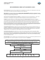
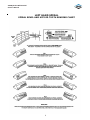
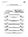
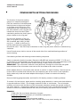
1
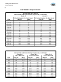
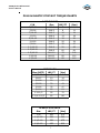
Service Manual
36R Hydraloc Differential Axle
ASM-0159
September 2009
36R Hydraloc Differential
Service Manual
FOREWORD
This manual has been prepared to provide the customer and maintenance personnel with
information and instructions on the maintenance and repair of Dana Products.
Extreme care has been exercised in the design and selection of materials and
manufacturing of these units. The slight outlay in personal attention and cost required to
provide regular and proper lubrication, inspection at stated intervals, and such
adjustments as may be indicated will be reimbursed many times in low cost operation and
trouble free service.
In order to become familiar with the various parts of the product, it’s principle of
operation, troubleshooting, and adjustments it is urged that mechanics study the
instructions in this manual carefully and use it as a reference when performing
maintenance and repair operations.
Whenever repair or replacement of component parts is required, only Dana approved
parts as listed in the applicable parts manual should be used. Use of “will fit” or
non-approved parts may endanger proper operation and performance of the equipment.
Dana does not warrant repair, replacement parts or failures resulting from the use of parts
which are not supplied or approved by Dana. Important: Always furnish serial and model
numbers when ordering parts.
SAFETY PRECAUTIONS
To reduce the chance of personal injury and/or property damaged, the following
instructions must be carefully observed.
Proper service and repair are important to the safety of the service technician and the
safe, reliable operation of the machine. If replacement parts are required the part must be
replaced with a Dana specified replacement part. Do not use a replacement part of lesser
quality.
The service procedures recommended in this manual are effective methods of performing
service and repair. Some of these procedures require the use of purpose designed tools.
Accordingly, anyone who intends to use a replacement part, service procedure or tool
which is not recommended must first determine that neither his safety or the safe
operation of the machine will be jeopardized by the replacement part, service procedure
or tool selected.
It is important to note that this manual contains various “Cautions and Notices” that must
be carefully observed in order to reduce the risk of personal injury during service or repair.
Improper service or repair may damage the unit or render it unsafe. It is important to
understand that these “Cautions and Notices’ are not exhaustive. It is impossible to warn
of all possible hazardous consequences that may result from following or failing to follow
these instructions.
1
36R Hydraloc Differential
Service Manual
TABLE OF CONTENTS
1.
2.
3.
4.
6.
7.
8.
9.
10.
11.
12.
13.
14.
15.
Forward and Caution
Table of Contents
Bearing Heating and Freezing Guidelines
Cleaning and Inspection
Fastener Torque Chart
Plug and Elastic Stop Nut Torque Charts
Recommended Lubricants
Gear Tooth Contact Chart – LH
Gear Tooth Contact Chart – RH
Cross Section Illustration
Inner Pinion Bearing Staking
Pinion Depth Setting Procedure
Differential Assembly Exploded View
Differential Assembly Parts Description
DISASSEMBLY
16.
16.
19.
Differential Assembly Removal
Differential and Carrier Disassembly
Differential Disassembly
REASSEMBLY
21.
Differential Reassembly
25.
Pinion Bearing Setting Procedure
27.
Ring Gear and Pinion Backlash Setting Procedure
27.
Ring Gear to Pinion Distance Setting Procedure
29.
Differential Installation
2
36R Hydraloc Differential
Service Manual
BEARING HEATING AND FREEZING GUIDELINES
Bearings often must be cooled or heated to aid in assembly or removal. Since
temperature extremes can cause permanent bearing metallurgical damage, it is important
to take proper precautions and use correct methods when heating and cooling bearings.
Cups that are to be assembled in hubs or housings with a press fit may be shrunk in a
deep freeze unit. Standard class bearings should not be cooled below -65° F (-54° C). In
addition to cooling the bearing cup, in some instances it may be necessary to heat the
housing.
To control temperature, is best to use a thermostat along with a freezer unit or a properly
calibrated thermometer. If a suitable freezer or thermometer is not available, your Timken
service representative can suggest liquid combinations that freeze the bearing cup at the
optimal temperatures. Regardless of the method, check the cup’s final seating against the
housing shoulder with feeler gauges.
Take extreme care that standard product bearings are never heated above
149° C [300° F]. If bearings are heated above this temperature, their metallurgical
structure may soften, rendering them unsuitable for use.
There are a number of recommended methods for heating bearings. Electric ovens or
electrically heated oil baths may be used, but only when accompanied by proper
thermostatic control. If you use a hot plate to heat the oil, never rest bearings directly on
the bottom of the pan. Instead, protect bearings from the heat source with a simple wire
screen holder or similar device.
Use heat-resistant gloves to handle heated cones. Hold the hot cone solid against the cold
shoulder on the shaft until the cone grabs on to the shaft. The hot cone will pull away
from the cold shoulder unless it is held in position. Use .002 [.05 mm] feeler gages to
make sure the cone is fully seated against the shoulder after the parts are cooled. Many
loose bearing settings (excessive end play) are caused by an unseated cone working back
against the shoulder in service.
3
36R Hydraloc Differential
Service Manual
CLEANING AND INSPECTION
CLEANING
Clean all parts thoroughly using solvent type cleaning fluid. It is recommended that parts
be immersed in cleaning fluid and agitated slowly until parts are thoroughly cleaned of all
old lubricants and foreign materials.
CAUTION: Care should be exercised to avoid skin rashes, fire hazards and inhalation
of vapors when using solvent type cleaners.
BEARINGS
Remove bearings from cleaning fluid and strike larger side of cone flat against a block of
wood to dislodge solidified particles of lubricant. Immerse again in cleaning fluid to flush
out particles. Repeat above operation until bearings are thoroughly clean. Dry bearings
using moisture free compressed air. Be careful to direct air stream across bearings to
avoid spinning. Bearings may be rotated slowly by hand to facilitate the drying process.
HOUSINGS, COVERS AND CAPS
Clean interior and exterior of housings, bearing caps, etc., thoroughly. Cast parts may be
cleaned in hot solution tanks with mild alkali solutions, providing these parts do not have
ground or polished surfaces. Parts should remain in solution long enough to be thoroughly
cleaned and heated. This will aid the evaporation of the cleaning solution and rinse water.
Parts cleaned in solution tanks must be thoroughly rinsed with clean water to remove all
traces of alkali. Cast parts may also be cleaned with steam cleaner.
CAUTION: Care should be exercised to avoid skin rashes and inhalation of vapors
when using alkali cleaners. Thoroughly dry all parts cleaned immediately by using
moisture-free compressed air or soft lintless absorbent wiping rags free of abrasive
materials such as metal filings, contaminated oil or lapping compound.
INSPECTION
The importance of careful and thorough inspection of all parts cannot be overstressed.
Replacement of all parts showing indication of wear or stress will eliminate costly and
avoidable failures at a later date.
BEARINGS
Carefully inspect all rollers, cages and cups for wear, chipping or nicks to determine fitness
of bearings for further use. Do not replace a bearing without replacing the mating cup or
cone at the same time. After inspection, dip bearings in clean light oil and wrap in clean
lint free cloth or paper to protect them until installed.
OIL SEALS, GASKETS AND RETAINING RINGS
Replacement of spring loaded oil seals, gaskets, and snap rings is more economical when
unit is disassembled than to risk premature overhaul to replace these parts at a future
time. Loss of lubricant through a worn seal may result in failure of other more expensive
parts of the assembly. Sealing member should be handled carefully, particularly when
being installed. Cutting, scratching or curling under lip of seal seriously impairs its
efficiency. At reassembly, lubricate lips of oil seals with Multipurpose Lithium grease
“Grade 2”.
4
36R Hydraloc Differential
Service Manual
CLEANING AND INSPECTION - CONT.
GEARS AND SHAFTS
If Magna-Flux or a dye penetrant process is available use process to check parts. Examine
teeth and the ground/polished surfaces of all gears and shafts carefully for wear, pitting,
chipping, nicks, cracks, or scoring. If gear teeth are cracked or show spots where case
hardening is worn through, replace with new gear. Small nicks may be removed with
suitable hone stone. Inspect shafts to make certain they are not sprung, bent or have
twisted splines.
HOUSINGS, COVERS AND CAPS
Inspect housings and covers to be certain they are thoroughly cleaned and that mating
surfaces, bearing bores, etc. are free from nicks or burrs. Check all parts carefully for
evidence of cracks or conditions which can cause oil leaks or failures.
5
36R Hydraloc Differential
Service Manual
FASTENER TORQUE CHART
Size
1/4-20
1/4-28
5/16-18
5/16-24
3/8-16
3/8-24
7/16-14
7/16-20
1/2-13
1/2-20
9/16-12
9/16-18
5/8-11
5/8-18
3/4-10
3/4-16
STANDARD FASTENERS
Lubricated and Plated Bolts, CapScrews, and Studs
Grade 5
Grade 8
3 Radial Dashes On Bolt Head
6 Radial Dashes On Bolt Head
LBF/FT
LBF/FT
[Nm]
[Nm]
10
11
14
15
11
13
15
18
16
30
22
41
20
32
27
43
25
36
34
49
29
41
39
56
41
57
56
77
45
64
61
87
63
88
85
119
99
70
95
134
127
90
122
172
141
100
136
191
175
124
168
237
141
198
191
268
310
220
298
420
347
245
332
470
METRIC FASTENERS
Lubricated and Plated Bolts, CapScrews, and Studs
Class 8.8
Class 10.9
Class 12.9
8.8 on Bolt Head
Size
M4
M5
M6
M8
M10
M12
M14
M16
M18
M20
M22
M24
LBF/FT
2.2
4.4
7.4
18
36
63
100
155
221
313
428
538
[Nm]
3
5.9
10
25
49
85
135
210
300
425
580
730
10.9 on Bolt Head
LBF/FT
3.2
6.4
11
26
51
92
147
229
317
450
605
774
6
[Nm]
4.4
8.7
15
36
72
125
200
310
430
610
820
1050
12.9 on Bolt Head
LBF/FT
7.4
7.4
13
32
62
107
173
269
369
524
708
900
[Nm]
10
10
18
43
84
145
235
365
500
710
960
1220
36R Hydraloc Differential
Service Manual
PLUG & ELASTIC STOP NUT TORQUE CHARTS
O-RING PLUGS
Size
LBF/FT
24K-1
5
24K-2
8
24K-3
10
24K-4
13
24K-5
15
24K-6
25
24K-7
35
24K-8
50
24K-9
60
24K-10
75
24K-11
85
24K-12
85
P/N
5/16-24
3/8-24
7/16-20
1/2-20
9/16-18
3/4-16
7/8-14
1 1/16-12
1 3/16-12
1 5/16-12
1 5/8-12
1 7/8-12
PIPE PLUGS
Size (NPTF)
LBF/FT
1/16-27
7
1/8-27
10
1/4-18
20
3/8-18
30
1/2-14
35
3/4-14
45
[Nm]
9
14
27
41
47
61
1-11 1/2
55
75
1 1/4-11 1/2
65
88
ELASTIC STOP NUTS
Size
LBF/FT
[Nm]
1-20
200
270
1 1/4-18
250
340
1 1/2-18
350
475
1 3/4-12
450
610
7
[Nm]
7
11
14
18
20
34
47
68
81
102
115
115
36R Hydraloc Differential
Service Manual
RECOMMENDED LUBRICANTS FOR DRIVE AXLES
Recommendations: Extreme pressure gear lubricant is recommended for use in all drive-steer and rigid drive axles except
where explicitly stated differently by Dana Off-Highway Products Engineering.
Mineral Based: Acceptable lubricants must meet API GL-5/MT or MIL-PRF2105E qualifications. The highest viscosity
grade must be used given the prevailing ambient temperatures from the chart below. Limited slip designated GL-5 oil brands
are preferred for quiet operating characteristics.
Universal Tractor Transmission Oils (UTTO Fluids): Acceptable lubricants must meet Dana MS266 or J. Deere J20C
specifications. Use the highest viscosity grade for the ambient temperatures from the temperature chart below.
Synthetics: Synthetic lubricants are recommended providing they meet API GL-5/MT-1 qualifications. The highest
viscosity grade must be used given the prevailing ambient temperatures from the chart below. In general synthetic oils have a
lower pressure viscosity response than mineral oil lubricants as the contact pressure between the gears increases. This
produces a thickening of the mineral oil at the contact point. This increase in viscosity helps to maintain lubricant film
thickness reducing the possibility of surface and spalling fatigue. Synthetic lubricants do not thicken as much under pressure
unless specifically formulated to do so. Before using a synthetic lubricant in heavy applications, the customer must check
with the lubricant supplier on the issue of high-pressure lubricant applications.
Normal Oil Change Intervals: Oil change intervals for mineral based lubricants in normal environmental and duty cycle
conditions is 1000 hours in all off-highway applications and 10,000 miles in on-highway applications. Severe or sustained
high operating temperature or very dusty atmospheric conditions will result in accelerated deterioration or contamination.
Judgement must be used to determine the required change intervals for extreme conditions.
Extended Oil Change Interval: Extended oil service may result when using synthetic lubricants. Appropriate change
intervals must be determined for each application by measuring oxidation and wear metals over time to determine a base line.
Wear metal analysis can provide useful information, but an axle should not be removed from service based solely on this
analysis. Vehicles, which are prone to high levels of ingested water in the axle, or water as a result of condensation, should
not use extended drain intervals.
Friction Modifiers: Friction modifiers may be used with the lubricant to reduce Posi-Torq (limited slip) differential noise or
liquid cooled brake noise. If friction modifiers are used, follow instructions on TSB 278E.
The use of aftermarket lubricant additives other than those specified is not
recommended and may reduce the life of the axle and void the warranty!
Viscosity Based on Prevailing Ambient Temperature
UTTO – SAE 15-30
UTTO – SAE 30
SAE 90
80W90
75W90
75W
-40
-40
-30
-22
-20
-4
-10
14
0
32
10
50
8
20
68
30
86
40
104
50
122
36R Hydraloc Differential
Service Manual
LEFT HAND SPIRAL
SPIRAL BEVEL AND HYPOID TOOTH BEARING CHART
9
36R Hydraloc Differential
Service Manual
RIGHT HAND SPIRAL
SPIRAL BEVEL AND HYPOID TOOTH BEARING CHART
10
36R Hydraloc Differential
Service Manual
CROSS SECTION
11
36R Hydraloc Differential
Service Manual
INNER PINION BEARING STAKING
When the inner pinion bearing or the pinion shaft and ring gear are being replaced staking of the
pinion end to the inner pinion bearing is required. If a staking groove is in the pinion shaft use
procedure shown in Figure “A” and a square end staking tool as shown. If pinion has no staking
groove use procedure in Figure “B” and a standard prick punch to upset the metal over the bearing
inner race.
12
36R Hydraloc Differential
Service Manual
PINION DEPTH SETTING PROCEDURE
The function of the pinion setting
gauge is to measure the distance
from the centerline of the differential
bearing bores to the ground surface
on the gear end of the pinion. This
measurement when subtracted from
the value etched on the ring gear will
indicate the size of the shim pack
required to position the pinion gear in
proper relation to the ring gear.
On the outer diameter of the ring
gear, a ring gear to pinion distance
will be etched, add .4649 [11.808
mm] to it. (.4649 [11.808 mm] is
half the thickness of the gauge bar).
Record this value. This value may be different on each ring and pinion set due to manufacturing
variations.
Use a file and emery cloth to remove all burrs and nicks from machined bearing surfaces of
carrier housing.
Paint bearing surfaces with bearing contact checking compound.
Insert an extension depth micrometer (Starrett #44B-6RC and extension #99347 7” [178 mm]
or equivalent is recommended) into the guide bore of the micrometer arbor and slide clamps over
base of micrometer. With the thumb screws reacting on base, secure micrometer.
IMPORTANT: The micrometer extension must pass freely through the micrometer bar guide
bore and base of the micrometer must rest on the micrometer arbor when mounted.
Mount adapter discs on micrometer arbor and set in position in carrier housing. Exercise care to
be sure that micrometer and extension do not contact any part of the carrier in this operation.
Apply pressure by hand and rotate adapter discs slightly to obtain a contact with bearing
surfaces.
Remove checking gauge assembly and check for full bearing contact on bearing surfaces.
If contact is full and proper, again position checking gauge assembly in carrier and check distance
to ground surface on pinion. Do not apply pressure to arbor or micrometer. Turn micrometer
carefully and evenly until the flat tip of the micrometer extension contacts the ground surface of
the pinion squarely. Subtract this reading from the value previously recorded and this equals the
amount of shims to be added between the inner pinion bearing cup and the carrier housing.
EXAMPLE:
5.289 [134.341 mm] Value etched on ring gear.
+0.469 [011.913 mm] Constant (1/2 thickness of gauge bar).
5.758 [146.253 mm] Total
-5.728 [145.491 mm] Initial micrometer reading.
0.030 [
.762 mm] Add this value in shims under inner pinion bearing cup.
13
36R Hydraloc Differential
Service Manual
DIFFERENTIAL ASSEMBLY EXPLODED VIEW
14
36R Hydraloc Differential
Service Manual
DIFFERENTIAL ASSEMBLY PARTS DESCRIPTION
ITEM QTY DESCRIPTION
1
1
AXLE HOUSING
2
1
VENT
3
1
FILL PLUG
4
2
PLUG O-RING
5
1
MAGNET DRAIN PLUG
6
1
CARRIER AND CAP ASSY.
7
1
CARRIER
8
1
CARRIER CAP
9
4
CARRIER CAP WASHER
10
4
CARRIER CAP BOLT
11
1
DOWEL PIN
12
30
LOCK WASHER
13
24
BOLT
14
1
O-RING
15
2
ADJUSTING NUT LOCK BOLT
16
2
NUT LOCK
17
2
TAPERED BEARING
18
2
ADJUSTING NUT
19
1
ROLLER BEARING
20
1
CENTER PINION BEARING
21
1
PINION SPACER
22
1
O-RING
23
AR
BEARING RETAINER SHIM
24
1
BEARING RETAINER
25
6
BEARING RETAINER BOLT
26
2
BEARING RETAINER PLUG
27
1
OUTER PINION BEARING
28
1
OIL SEAL
33
1
PINION NUT O-RING
34
1
PINION NUT
35
1
CASE ASSEMBLY
36
16
CASE BOLT
37
16
CASE WASHER
38
1
THRUST WASHER
ITEM QTY DESCRIPTION
39
1
SIDE GEAR
40
1
CLUTCH SIDE GEAR
41
1
THRUST WASHER
42
1
DIFFERENTIAL CROSS
43
4
DIFFERENTIAL PINION GEAR
44
4
THRUST WASHER
45
1
DIFFERENTIAL CASE SEAL
46
1
RING & PINION SET
47
12
RING GEAR MOUNTING BOLT
48
1
CASE FLANGE HALF
49
1
PLUG
50
12
NUT
51
1
CLUTCH PISTON
52
1
OUTER SEALING RING
53
1
INNER SEALING RING
55
1
SEAL RETAINER
56
6
OIL PASSAGE PLUG
57
2
PISTON RING
58
1
BALANCE PISTON
59
3
O-RING
60
1
NIPPLE - PRESSURE PORT
61
1
O-RING
62
1
FILTER
63
2
PLUG
64
1
NIPPLE - TANK PORT
65
1
O-RING
66
1
EXTENSION TUBE
67
1
SEALING RING
68
1
CLUTCH DRIVER
69
1
SNAP-RING
70
6
INNER DISC.
71
6
OUTER DISC.
72
1
PINION FLANGE
73
AR
PINION BEARING SHIM
15
36R Hydraloc Differential
Service Manual
DIFFERENTIAL ASSEMBLY REMOVAL
DISASSEMBLY
Figure 1
Remove differential to axle bolts and washers.
Figure 4
Loosen flange nut.
Figure 2
Install (4) pusher bolts in the threaded holes in the
carrier flange. Attach lifting device to input flange.
Figure 5
Remove flange nut.
Remove flange nut o-ring.
Figure 3
Tighten (4) pusher bolts evenly and lift differential
assembly straight up and off of dowel pin.
Mount differential on suitable overhaul stand.
IMPORTANT: Using a dial indicator check and record ring
gear backlash at this time. This information is necessary
for reassembly unless a new gear set is installed.
Figure 6
Remove flange.
16
36R Hydraloc Differential
Service Manual
Figure 7
Remove tank and pressure port nipples.
Figure 10
Remove seal retainer. Remove (2) seal rings.
Figure 8
Remove (2) adjusting nut lock bolts.
Figure 11
Match mark differential caps for reassembly.
Remove (4) cap bolts and washers.
Figure 9
Remove (2) adjusting nut locks.
Figure 12
Remove (2) differential caps.
17
36R Hydraloc Differential
Service Manual
Figure 13
Remove (2) differential bearing adjusting nuts.
Figure 16
Remove differential assembly from carrier.
Remove bearing cones.
Figure 14
Remove (12) ring gear mounting bolt nuts.
Figure 17
Remove (6) bearing retainer bolts and washers.
Figure 15
Drive ring gear bolts through ring gear and remove.
Figure 18
Remove pinion shaft and bearing retainer.
18
36R Hydraloc Differential
Service Manual
Figure 19
Remove shims. Press pinion from bearing retainer.
Remove bearing cups and oil seal from retainer.
Figure 22
Remove inner and outer piston seals.
DIFFERENTIAL DISASSEMBLY
Figure 20
Mark flange half, clutch housing and case half with alignment
marks for reassembly. Remove case flange half.
Figure 23
Remove ring gear.
Figure 24
Remove clutch driver snap ring.
Figure 21
Install a seal retainer and piston rings as shown.
Carefully and slowly apply compressed air to port in
distributor to remove piston. Using appropriate puller
remove bearing cone if replacement is required.
19
36R Hydraloc Differential
Service Manual
Figure 25
Remove friction and reaction plates.
Figure 28
Remove (16) case cap half to
clutch housing bolts and washers.
Figure 26
Remove clutch driver.
Figure 29
Separate case halves.
Figure 27
Remove differential case seal.
Using appropriate puller remove bearing cone if
replacement is required.
Figure 30
Remove side gear and thrust washer
from case cap half.
20
36R Hydraloc Differential
Service Manual
DIFFERENTIAL REASSEMBLY
NOTE: All parts must be lubricated
with axle lubricant at reassembly.
No part should assembled dry.
Figure 31
Remove differential cross, pinions
and thrust washers from clutch housing.
Figure 34
Position side gear thrust washer in clutch housing.
Figure 32
Remove clutch side gear.
Figure 35
Install clutch side gear.
Figure 33
Remove clutch side gear thrust washer.
Figure 36
Assemble differential cross, (4) pinions and
(4) thrust washers and install as an assembly.
21
36R Hydraloc Differential
Service Manual
Figure 37
Position standard side gear on
pinion and cross assembly.
Figure 40
Install (16) case bolts and install with washers.
Tighten to 71-88 Nm [52-65 LBF/FT].
Figure 38
Place side gear thrust washer on side gear.
Figure 41
Position clutch driver on splines of clutch side gear.
Figure 39
Using appropriate driver install bearing cone on case
cap half. Position case cap half and bearing on clutch
housing. NOTE: Be sure to match up alignment
marks made during disassembly.
Figure 42
Install clutch driver to gear snap ring.
22
36R Hydraloc Differential
Service Manual
Figure 46
Install new inner and outer seal rings on piston.
Lubricate rings and piston bore in housing with grease.
Figure 43
Install (1) friction plate in clutch housing.
NOTE: Identify notch in splines.
Figure 44
Install (1) reaction plate.
Figure 47
Using soft faced hammer evenly tap piston into clutch
housing. NOTE: Be careful not to damage seal rings.
Figure 45
Install friction plate aligning notch with previous friction
plate. Alternate reaction and friction plates until (6) of each
are installed. NOTES: The notch in each friction plate must
be aligned with the notch in the proceeding plate. Be sure
plates are lubricated with axle lubricant on both sides.
Figure 48
Align screw holes and match marks made at
disassembly on flange half case with clutch housing.
23
36R Hydraloc Differential
Service Manual
Figure 51
Press inner bearing on pinion.
Figure 49
Install case flange half. Using appropriate driver
install bearing cone on flange half case.
Figure 52
Stake pinion to bearing inner race
in (4) places equally spaced around diameter.
Refer to instructions on page 12.
Figure 50
Turn differential body assembly over. Heat ring gear
to 93-100°C [200-212°F] and install using (2) ring
gear bolts located 180° apart in ring gear to aid in
alignment of bolt holes.
CAUTION: Use gloves to avoid injury.
Temporaraly install (2) nuts
and tighten to 135 Nm [100 LBF/FT].
Figure 53
Press center bearing on pinion shaft with the large
diameter of bearing towards gear teeth.
24
36R Hydraloc Differential
Service Manual
Figure 56
Position bearing retainer on pinion.
Press outer bearing cone in place.
Figure 54
If the ring and pinion, tapered bearings or bearing
retainer were not replaced install the original bearing
spacer and shim. If new parts are used a shim kit
should be used. Install the spacer provided in the
kit along with same thickness shim removed
plus an additional shim.
PINION BEARING SETTING PROCEDURE
Figure 57
Install input flange, and flange nut. Tighten nut to
minimum 800 Nm [590 LBF/FT] (dry thread). Secure
bearing retainer in vise to allow pinion to rotate.
Using an “inch pound” torque wrench check rolling
resistance torque. Rolling resistance should be
1.1-3.4 Nm [10-30 LBF/IN]. If not within
specifications add shim thickness to decrease torque
or remove shim to increase torque.
IMPORTANT: This rolling torque check must be
made again with seal retainer assembly installed in
the carrier housing. Install seal retainer assembly in
housing with original bearing cage shims and (4)
retainer screws and washers. Tighten screws to
182-202 Nm [134-149 LBF/FT]. Repeat rolling
resistance check. Rolling resistance must be
1.1-3.4 Nm [10-30 LBF/IN].
NOTE: The flange will be removed after ring
gear to pinion contact and backlash has been set.
Figure 55
Install center and outer bearing
cups in bearing retainer.
25
36R Hydraloc Differential
Service Manual
Figure 58
Insert a bar as shown to facilitate lifting. Position
differential into carrier, tilting it so that ring gear will
clear inner bearing bore boss in carrier.
Figure 61
Position bearing caps on bearings and adjusting
nuts making sure match marks made during
disassembly are properly aligned.
Install (4) cap bolts and washers.
NOTE: Tighten to snug up.
Do not torque at this time.
Figure 59
Position differential bearing cups on
each side over bearing cones.
Figure 62
Remove (2) temporally installed ring gear bolt nuts.
Install (10) ring gear mounting bolts. Apply Loctite
242 or equivalent to bolt threads and install (12) nuts.
Hold pinion flange and tighten nuts to
182-202 Nm [134-149 LBF/FT].
Figure 60
Install adjusting nuts on each side against bearing
cup. NOTE: Turn adjusting nuts by hand
to be sure of proper thread alignment.
26
36R Hydraloc Differential
Service Manual
RING AND PINION BACKLASH SETTING
Figure 65
Remove differential assembly from carrier.
Refer to Figures 11-13.
Figure 63
Use a dial indicator as shown. Move ring gear by
loosening one adjusting nut and tightening
opposite adjusting nut. Adjust position until gear
backlash is to backlash specifications of
0.23-0.33 mm [.009-.013"]. Use 0.33 mm [.013”] for
new ring gear set, or adjust to backlash recorded at
disassembly for used gears. Refer to Figure 3.
When proper backlash is achieved, tighten opposite
adjusting nut to remove all end play on tapered
bearings. Using only thumb and forefinger, move ring
gear. When ring gear becomes difficult to move,
preload on bearing is set. Recheck backlash.
RING GEAR TO PINION MOUNTING
DISTANCE SETTING PROCEDURE
If mounting distance pinion setting gauge is used
follow instruction supplied with gauge.
Refer to procedure on page 13.
Use the following procedure when the
pinion setting gauge is not used:
Check ring and pinion gear for proper tooth contact.
Paint ring gear with a gear tooth marking compound.
When ring and pinion gears are rotated, the
compound is squeezed away by the contact of the
teeth, leaving bare areas the exact size, shape and
location of the contacts. As a rule, painting about 10
or 12 teeth is sufficient for checking purposes.
Sharper impressions may be obtained by applying a
small amount of resistance to the ring gear with a
flat steel bar and using a wrench to rotate the pinion.
Gears should be rotated, under slight load, until ring
gear has turned at least one revolution in both
directions. Check tooth contact pattern on drive
side (convex side) of ring gear teeth. Coast side will
automatically correct when drive side pattern is
correct. Refer to gear tooth contact charts
on pages 9&10. If proper tooth contact pattern is
not as shown, readjust backlash or, add to or
subtract from shim pack between bearing cage
flange and differential housing. Addition of or
subtraction of shims should be made in small
increments until proper contact is established. After
optimum tooth contact is made, the differential and
pinion must be removed from the carrier, this will
allow for proper sealing measures at reassembly.
Figure 64
Figure 66
Remove pinion shaft and retainer assembly from
carrier. Remove flange from pinion.
Remove pinion from bearing retainer.
Figure 67
Apply Loctite 515 or equivalent to outer diameter of
pinion oil seal. Using appropriate driver install seal
with lip of seal facing in/down.
27
36R Hydraloc Differential
Service Manual
Figure 71
Install flange and flange o-ring. Apply Loctite 270 or
equivalent to threads and install flange nut.
Tighten to 600-800 Nm [443-590 LBF/FT].
Figure 68
Install bearing retainer shims. NOTE: Install with
reference hole in shims opposite ring gear.
Figure 69
Press pinion into bearing retainer assembly. Install
pinion and retainer assembly in carrier housing.
NOTE: Line up oil holes in retainer and carrier housing.
Figure 72
Reinstall bearing caps, cap bolts and washers.
Tighten to snug up. Refer to Figures 63 & 64 to
set ring gear backlash, bearing preload and recheck
tooth contact pattern. After optimum settings are
made remove cap bolts and adjusting nuts, one side
at a time, apply Loctite 242 or equivalent to bolt
threads, Loctite 222 or equivalent to adjusting nut
threads reinstall and tighten bolts to
495-611 Nm [365-451 LBF/FT].
NOTE: Recheck for proper ring gear backlash and
bearing adjustment after final torquing.
Figure 70
Install (6) bearing retainer bolts and washers.
Tighten to 182-202 Nm [134-149 LBF/FT].
28
36R Hydraloc Differential
Service Manual
DIFFERENTIAL INSTALLATION
Figure 73
Install (2) piston rings on carrier journal. Lubricate
rings and seal retainer with grease.
Install seal retainer.
Figure 76
Install new carrier to axle housing o-ring on carrier.
Install alignment dowel pin in axle housing.
Figure 74
Apply Loctite 242 or equivalent to bearing
nut lock bolt and install with nut lock.
Tighten to 16-26 Nm [22-19 LBF/FT].
Repeat with bolt and nut lock on opposite side.
Figure 77
Apply light coat of grease to pilot on flange of carrier.
Lower assembly carefully into axle housing. Align
dowel pin with hole in carrier. Tap lightly at dowel pin
location while lowering assembly into position.
Figure 75
Install new square cut seals and o-rings to nipples.
Install nipples in carrier housing and tighten to
40-50 Nm [29-37 LBF/FT].
29
36R Hydraloc Differential
Service Manual
Figure 78
Install (24) carrier to
axle housing bolts and washers.
Figure 79
Tighten (24) bolts to 182-202 Nm [134-149 LBF/FT].
30
Copyright 2012 Dana Holding Corporation
All content is subject to copyright by Dana and may not
be reproduced in whole or in part by any means,
electronic or otherwise, without prior written approval.
THIS INFORMATION IS NOT INTENDED FOR SALE OR
RESALE, AND THIS NOTICE MUST REMAIN ON ALL
COPIES.
For product inquiries or support,
visit www.dana.com or call 419-887-6445
For other service publications,
visit www.SpicerParts.com/literature.asp
For online service parts ordering,
visit www.SpicerParts.com/order.asp