1
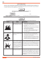
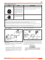
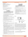
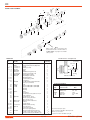
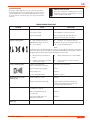
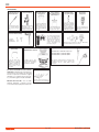
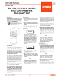
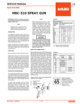
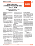
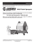
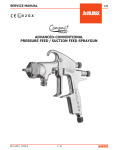
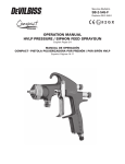
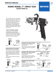
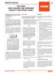
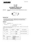
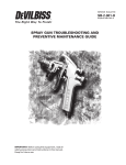
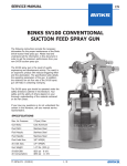
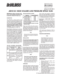
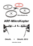
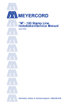
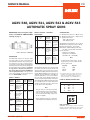
SERVICE MANUAL
EN
AGXV-540, AGXV-541, AGXV-542 & AGXV-543
AUTOMATIC SPRAY GUNS
IMPORTANT: Before using this equipment, read SAFETY PRECAUTIONS
starting on page 2.
U.S. Patent No. 5,364,033
DESCRIPTION
The AGXV high volume, low pressure spray
gun (spray pistol) is used on automatic and
semi-automatic machines where mass production spraying is necessary, or hand spraying is
not accurate enough. Models and application
information follows. All models are designed to
provide maximum transfer efficiency by limiting
air cap pressure to 10 psi (0.7 bar) (in the U.S.,
this complies with rules issued by SCAQMD and
other air quality authorities). Air cap pressure
can be measured with an optional air cap test
kit. See "ACCESSORIES" on Page 8.
CHART 1 MODELS
Model No.
(Available
Typical
Tip Sizes)
Applications
HVLP
Air Cap
Used
AGXV-540 Most common
33A
(E, FF, FX) finishing materials including some
waterborne and
chlorinated.
AGXV-541
(D, E, FF, FX)
High solids (low
VOC's) coatings
which are difficult
to atomize with
HVLP, or high
flow rates.
Fluid
Tip/Needle
Construction
400 Gr. S/S
303 Gr. S/S
Air
Cap
No.
Complete
Air Cap
No.
*Typical Pattern Size
and Shape
Typical
Application
33A JGHV-101-33A 9" (229 mm)
long, tapered
ends, similar to
30 air cap.
Most common finishing
materials, up
to 12 oz./min.
(360 cc)
46MP JGHV-101-46MP 11" (280 mm)
long, straight
sided, similar to
704 air cap.
Low VOC
materials, 12
to 16 oz./min.
(360 to
480 cc)
83MP JGHV-101-83MP 13" (330 mm)
long, straight
sided similar to
765 air cap.
Low VOC
materials,
17 oz./min.
(510 cc) and
above.
* Actual pattern length dependent upon fluid tip (nozzle) ID,
coating material flow rate, air pressure and fan pressure.
Most finishing materials can be atomized with
the 33A air cap. The 33A cap should be used
where possible as it consumes less air volume
(CFM) and has slightly better transfer efficiency
than the 46 MP or 83MP air caps. However, more
difficult to atomize materials (i.e. low VOC's) or
high flow applications over 12 oz./min. (360 cc/
min.), are ideal for the 46 MP maximum performer air cap, fluid tip and baffle combination.
Also available is the 83MP (maximum performer)
for even higher flows 17 oz./min. (510 cc/min.)
and above and higher viscosities. Refer to the
air cap chart for more information.
Note
46MP or 400 Gr. S/S
83MP 303 Gr. S/S
AGXV-542 Waterbornes and
33A
(FF, FX)
other corrosive
materials (below
7pH)
303 Gr. S/S,
Poly.
AGXV-543 Same as AGXV-
46MP
(FF, FX)
541 except for
more corrosive
materials
(below 7pH)
303 Gr. S/S,
Poly.
SB-2-628-V (6/2014)
CHART 2 AIR CAPS – PATTERNS –
APPLICATION
This gun may be used with chlorinated
solvents. Aluminum is not used in fluid passages. If using chlorinated solvents, make
sure all other fluid handling components
are also compatible.
A list of materials used in the construction
of this equipment is available upon request.
SPECIFICATIONS
P1 – Maximum Inlet Pressure – 100 PSI (7 bar)
P2 – Maximum Fluid Pressure – 100 psi (7 bar)
P3 – Cylinder Air Pressure
– Min. **50 psi (3.5 bar)
– Max. 100 psi (7 bar)
Weight without mounting stud – 26 oz. (738 g)
Weight with mounting stud – 30.5 oz. (865 g)
Mounting stud diameter – 3/4" (19 mm)
Wetted Parts – 300 and 400 S/S, PTFE, Poly.
(See Chart 2 for tip/needle information)
Hose Connections –
Fluid Inlet – 3/8" NPS(M)
Cylinder Air – 1/4" NPS(M)
Atomization Air – 1/4" NPS(M)
Note
For HVLP operation (max. 10 psi, - 0.7 bar
cap pressure), do not exceed the air inlet
pressure given below.
PSI (bar)
Cap No.
57 (4)
50 (3.4)
45 (3.1)
83MP
46MP
33A
**For installations where 50 psi (3.4 bar) cylinder air is not
available, the inner (red) piston spring can be removed
which lowers the minimum cylinder air to approxi mately 37 psi (2.5 bar). Refer to "OPERATION", Pg. 4
FLUID TIP (NOZZLE) ORIFICE SIZES
Inchmm
D .086"2.2
E .070"1.8
FF .055"1.4
FX .042"1.1
G
0.028
.7
CA PROP
65
PROP 65 WARNING
WARNING: This product contains chemicals
known to the State of California to cause cancer
and birth defects or other reproductive harm.
1 / 12
EN
SAFETY PRECAUTIONS
This manual contains important information that ALL users should know and understand BEFORE using the equipment. This
information relates to USER SAFETY and PREVENTING EQUIPMENT PROBLEMS. To help you recognize this information, we
use the following terms to draw your attention to certain equipment labels and portions of this manual. Pay special attention
to any label or information that is highlighted by one of these terms:
Important information to alert you to a situation that might cause
serious injury or loss of life if instructions are not followed.
Note
Important information that tells how to prevent
damage to equipment.
Information that you should pay special attention to.
The following hazards may occur during the normal use of this equipment. Please read the following chart.
HAZARD
CAUSE
SAFEGUARDS
Fire
Solvents and coatings can be
highly flammable or combustible, especially when sprayed.
1. Adequate exhaust must be provided to keep the air free
of accumulations of flammable vapors.
2. Smoking must never be allowed in spray area.
3. Fire extinguishing equipment must be present in the
spray area.
4. Static discharges must be prevented. Ground (earth) all
conductive objects in the spray area, such as a cleaning
solvent bucket, fire extinguisher, etc.
5. When using solvents for cleaning:
•Those used for equipment flushing must have a flash
point equal to or greater than that of the coating.
•Those used for general cleaning must have flash points
above 100°F (37.8°C).
Inhaling Toxic Substances
Certain materials may be harmful
if inhaled, or if there is contact
with the skin.
1. Follow the requirements of the Material Safety Data
Sheet supplied by coating material manufacturer.
2. Adequate exhaust must be provided to keep the air free
of accumulations of toxic materials.
3. Use a mask or respirator whenever there is a chance of
inhaling sprayed materials. The mask must be compatible with the material being sprayed and its concentration. Equipment must be as prescribed by an industrial
hygienist or safety expert, and be NIOSH approved.
Explosion Hazard –
Incompatible Materials
Halogenated hydocarbon solvents- for example: methylene
chloride and 1,1,1,- Trichloroethane are not chemically compatible with the aluminum that
might be used in many system
components. The chemical reaction caused by these solvents
reacting with aluminum can
become violent and lead to an
equipment explosion.
The AGXV spray gun (spray pistol) can be used with these
solvents. However, aluminum is widely used in other spray
application equipment – such as material pumps, cups, regulators, valves, etc. Check all other equipment items before
use and make sure they can also be used safely with these
solvents. Read the label or data sheet for the material you
intend to spray. If in doubt as to whether or not a coating or
cleaning material is compatible contact your material supplier.
General Safety
Improper operation or maintenance may create a hazard.
Operators should be given adequate training in the safe use
and maintenance of the equipment (in accordance with the
requirements of NFPA-33, Chapter 15 in U.S.). Users must
comply with all local and national codes of practice and
insurance company requirements governing ventilation,
fire precautions, operation, maintenance and housekeeping
(in the U.S., these are OSHA Sections 1910.94 and 1910.107
and NFPA-33).
2 / 12
SB-2-628-V (6/2014)
EN
SAFETY PRECAUTIONS (Cont'd)
HAZARD
Noise Levels – Ear Injury
Solvent Spray
CAUSE
SAFEGUARDS
A continuous A-weighted sound
pressure level of this spray gun
(spray pistol) may exceed 85
dB(A) depending on the air cap/
fluid head setup being used.
Sound levels are measured using
an impulse sound level meter
and analyzer, when the gun is
being used in a normal spraying
application.
Always wear ear protection when using the gun.
During cleaning and flushing, solvents can be forcefully expelled
from fluid and air passages.
Some solvents can cause eye
injury.
Wear eye protection.
Details of actual noise levels produced by the various air cap/
fluid head setups are available upon request.
Misuse:
• All spray guns (spray pistols) project particles at high velocity and must never be aimed at any part of the body.
• Never exceed the recommended safe working pressures for any of the equipment used.
• The fitting of non-recommended or non-original accessories or spare parts may create hazardous conditions.
• Before dismantling the equipment for cleaning or maintenance all pressure, air and materials, must be isolated and released.
The disposal of waste materials must be carried out in an approved manner. Burning may generate toxic fumes. The removal or
waste solvents and coating materials should be carried out by an authorized local waste disposal service.
FIGURE 1 DIMENSIONS
FIGURE 2 TYPICAL INSTALLATION
INSTALLATION
Mount the gun with the stud (13) or on a 5/16" dia. rod tightening
adequately with the 1/4-28 X 1/4" set screws (Ref. 24). See
"ACCESSORIES" for mounting clamps.
Attach the trigger/cylinder air hose and the atomization air hose
to the connections as indicated by the markings on the gun body.
The air supply should be filtered and regulated. Attach the material
hose to the fluid inlet on the gun body. Fluid can be recirculated
by installing a fluid fitting (AGX-415) (order separately) at the
recirculating port. See Caution below.
Note
If replacing the atomization air connection (15) with an
elbow type connection, be aware of a possible air flow
(CFM) limitation. A 1/4" (6.4 mm) I.D. 90° elbow will only
pass 20 CFM @ 40 psi (566 l/min. 2.7 bar). Some air caps
require more than 20 CFM (566 l/min.). Spray performance
could be affected.
SB-2-628-V (6/2014)
The fluid inlet and recirculating ports have a tapered
seating surface intended for use with the AGX-415
fitting. Do not substitute other fittings as fluid leakage
will occur.
3 / 12
EN
OPERATION
CHART 3 FLUID TIPS (NOZZLE) AND NEEDLES
1. Mix, prepare and strain the material to be sprayed according to the
paint manufacturer’s instructions. Use a lint free mesh to strain the
material.
2. Turn on the cylinder air at source of supply. Supply air should be a
minimum of 50 PSI (3.5 bar). For consistant operation the pressure
should be regulated. If 50 psi (3.5 bar) cylinder air pressure is not
available, the red inner spring (31) can be removed. This allows a
minimum cylinder pressure of approximately 37 psi (2.6 bar).
Note
If the red inner spring (31) is removed, atomization pressure
should not exceed 70 psi (4.8 bar) (will result in gun not shutting off).
3. Turn the needle adjustment knob (25) counterclockwise several turns.
With the cylinder air on, turn the adjustment knob (25) clockwise until
it contacts piston (19) (for maximum fluid flow). Back knob out 1/2 turn.
Note
Due to close part tolerances, actuate the gun on and off 7 or
8 times to "break-in" the packings. Do this with the material
supply off.
4. Adjust the atomization air pressure to 50 PSI (3.5 bars) or less. Aways
attempt to keep the pressure as low as possible to minimize overspray.
The fluid pressure should be between 10 to 15 PSI (0.7 to 1.0 bar).
5. Open the hand valve and/or trip the automatic valve if installed in the
system and observe the spray pattern. Adjust the air and fluid pressures until the desired pattern is obtained. Control the fluid pressure
at the source of supply. If the desired regulation is not practical at this
point, restrict the flow by turning the adjustment knob (25) clockwise.
Tip Size
6. The width of the spray pattern is controlled by the adjusting valve (23)
marked “FAN” . With the “FAN” valve screwed fully clockwise, the
spreader air will be closed off causing a round pattern. By gradually
opening this valve, the pattern changes to a fan spray. The width is
determined by the amount the valve is opened. Atomization air is
adjusted by regulating the supply air to the gun.
Adjustments to fan may be controlled remotely by using the optional
KK-4955 fan control adapter to replace the AGG-403 control valve (23).
A separate solenoid valve is required to control on/off function. See
Figure 2A.
7. Close the automatic valves and begin operation.
FIGURE 2A AIR CIRCUIT EXAMPLE WITH
OPTIONAL KK-4955 REMOTE FAN CONTROL
Needle No.
400 Gr. Stainless Steel Tip/303 Stainless Steel Needle
E FF FX G FF FX D E
Inmm
.070" 1.8 AV-2115-E
.055" 1.4 AV-2115-FF
.042" 1.1 AV-2115-FX
.028" 0.8 AV-2115-G
.055" 1.4 AV-2120-FF
.042" 1.1 AV-2120-FX
.086" 2.2 AV-2120-D**
.070" 1.8 AV-2120-E**
AGX-402-E
AGX-402-FF
AGX-402-FX
AGX-402-G
AGX-402-FF
AGX-402-FX
AGX-402-D
AGX-402-E
303 Gr. Stainless Steel, U.H.M.W. Poly.
E .070"1.8 AV-4915-E
FF.055"1.4 AV-4915-FF
FX.042" 1.1 AV-4915-FX
FF.055"1.4 AV-4920-FF*
FX.042" 1.1 AV-4920-FX*
E .070"1.8 AV-4920-E
D .086"2.2 AV-4920-D
AGX-402-E
AGX-402-FF
AGX-402-FX
AGX-402-FF
AGX-402-FX
AGX-402-E
AGX-402-D
*For use with 46MP air cap.
**For use with 83MP air cap.
PREVENTIVE MAINTENANCE
Risk of Injury. Equipment and fluid may be under pressure.
Pressure in the system must be relieved before beginning the
cleaning procedure and before replacing any parts. Follow
the procedures in the literature provided with the system.
Back Pressure – 46MP and 83MP "Maximum Performer"
Due to the unique cone shape of the MP fluid tips (nozzle), a slight back
pressure is created against the fluid column. This will reduce the amount
of fluid output. To compensate, increase the fluid regulator pressure
slightly if necessary. With 10 PSI (0.7 bar) cap pressure, back pressures
are approximately 3.5 PSI (0.24 bar) with the 46MP and 2.0 PSI (0.14 bar)
with the 83MP.
Tip No.
Cleaning
1. Relieve air pressure from the pressure feed tank. Carefully follow the instructions in the bulletin sent with the tank.
2. Replace material in the container with a suitable solvent.
3. Repressurize the system.
4. Trigger the gun and repeat the procedure until the gun and hose
are thoroughly clean (solvent is clean when it looks the same
as when you first opened solvent container). A SolventSaver™
type hose and gun cleaner which supplies a mixture of air and
solvent can be used to most effectiverly clean the gun and hose
internal passages. See "Accessories" on back page. Wipe the
exterior of the gun with a solvent dampened cloth.
5. If a recirculating system is used, it may be necessary to fit a shut
off valve in the return line to ensure the fluid tip and forward
portion of the sprayhead passage are properly cleaned when
flushed with solvent.
Do not totally submerge the gun in solvent. It is possible
to wash solids into the air operating sections of the gun
which could damage piston "O" ring seals.
The air cap can be immersed in solvent for cleaning. If
the orifices are clogged, use a broom straw or toothpick
to remove the obstruction. Never use a steel wire or hard
instrument. This will damage the air cap and result in a
distorted spray pattern.
4 / 12
SB-2-628-V (6/2014)
EN
Plug (6) or Fluid Insert (9)
PARTS REPLACEMENT
Tools Required:
Adjustable Wrench or "C" Spanner
1/2" Box Wrench or 1/2" Socket Spanner (Ref. 3)
9/16" Open Wrench (Ref. 9) or 9/16" spanner
Long Neck Pliers (19) or long nose grips
Hex Wrench 1/8" for (Ref. 24)
Hex Wrench 3/16" for (Ref. 7)
Torque wrench (in.-lbs. and ft.-lbs.)
1/2" and 9/16" sockets
Halogenated Hydrocarbon solvents can chemically react
with aluminum. A risk of explosion or severe corrosion
will occur. The following assembly step must be carefully performed.
If replacing AGX-415 inlet fitting, or if it should loosen, follow the
assembly procedures below, and refer to Figure 3.
Fluid needle (28) , Tip (3) and Needle Packings (11)
1.Relieve all air and fluid pressure in the system.
2.Remove retaining ring (1) & air cap (2).
3.Remove fluid tip (3).
To avoid serious gun damage, do not remove the fluid
tip (nozzle) (3) from the spray gun (spray piston) when
the fluid inlet adaper (6 or 9) is removed. Doing so may
allow the stainless steel insert to break free from the
aluminum body, which is non-repairable.
4.It is recommended that both the fluid tip (nozzle) (3) and the
needle (28) be replaced at the same time. The needle packings
(11) should also be replaced when replacing the needle.
5.Remove adjusting knob (25).
6.Remove needle (28) with pliers.
7.Loosen four screws (7) and remove sprayhead (8).
8. With the sprayhead (8) removed, the packings (11) can be easily
removed and replaced.
9.Slide onto the new needle (28), in this order, 1 packing (11),
spring (12) and 1 packing (11). Be sure to orient the packings
as shown (Figure 4).
10.Assemble sprayhead (8) with retaining screws (7).
11.Tighten screws (7) with a 3/16 hexagon key 30-40 in. lbs.
(3.4 - 4.5 N-m) until the body is flush with sprayhead assembly.
12.Reassemble in reverse order.
1. If installing a used fitting, clean paint and thread sealant from
the fitting threads and gun body.
2.Screw the jam nut all the way onto the fitting. Then apply a
medium strength thread sealant (i.e. Loctite 242 blue, or equal)
to the first few threads of the fitting.
3.Install the AGX-415 fitting into the spray gun and tighten to a
maximum of 12 ft. lbs. (16.3 N-m) torque. (Do not overtighten,
damage may occur.)
4. Tighten the jam nut to 16 ft. lbs. (21.7 N-m) torque using a thin
9/16" open end wrench.
5. Use two adjustable wrenches when removing a hose connection from AGX-415 to prevent the inlet fitting from loosening.
FIGURE 3
16 ft. lbs. torque
Clean threads
Loctite 242, blue or equal
Piston (19) , O-Rings (17 & 18) and Air Packing (20)
1. Remove the piston housing (29) by removing the rear retaining
screws (7).
2.Remove fluid needle (28).
3.Remove springs (30, 31 & 27) and piston (19). Care must be
taken when removing the piston (19). Use a locking long nose
pliers to extract the piston by clamping on the inner ring on
the back of the piston.
4.Remove the air packing (20), "O" rings (17 & 18).
5. Wipe clean the bore of the cylinder. Replace the piston "O" rings
(17 & 18) and lightly lubricate with clean petroleum jelly. See
"LUBRICATION" section which follows.
6. To replace air packing (20) (inside of the piston), slide packing
(20) over the needle (28) with the lead-in chamfer towards the
fluid tip (nozzle) end of the needle. Insert the needle into the
piston (19). Hold the piston in your hand so that the tip end of
the needle is protruding downward (protect the needle from
damage). Lightly tap the blunt end of the needle to drive the
packing down into the piston. The needle will stop inside the
piston at a shoulder.
7.Fit complete assembly into gun.
8.Lubricate the outside of springs (31) and (27) (see "LUBRICATION" section), then re-install springs and piston housing (29)
and tighten down and torque mounting screws (7) 30-40 in.
lbs. (3.4 to 4.5 N-m).
9. Lubricate the adjustment knob threads (25) after cleaning with
•SSL-10 Gun Lube. Loosen the locking nut (26) before screwing
the adjustment knob in.
12 ft. lbs. torque
Do not overtighten.
LUBRICATION
The piston O-rings (17 and 18) must be lubricated when the piston
(19) is removed. Lightly lubricate with clean petroleum jelly. Do
not use silicone-based lubricants. Petroleum jelly is effective as a
lubricant up to approximately 110°F (43°C). Above 110°F (43°C),
petroleum jelly will become "liquid" and will not lubricate the O-rings
adequately. If the ambient temperature adjacent to the spray gun
exceeds 110°F (43°C), use Parker O-Lube or suitable high temperature
grease. This allows the spray gun to be used in temperatures up
to 150°F (65° C) continous without lubrication degradation.
Lubricate the outside of the larger piston spring (30) and needle
spring (27) with a light coating of non-silicone grease. Apply a thin
film of petroleum jelly (petroleum based grease) to the fluid needle
(28) as shown in the "Note" on Page 6.
•Material Safety Data Sheet available from DeVilbiss upon request.
SB-2-628-V (6/2014)
5 / 12
Note
Due to close part tolerances, after repairing the gun, actuate
the gun on and off 7 or 8 times to "break-in" the air packing
(20). Do this with the material supply off.
EN
FIGURE 4 GUN ASSEMBLY
15
16
18
13
14
32
9
17
20
33
22
12
8
7
24
1
2
19
21
23
11
3
10
4
5
6
25
7
27
28
26
Note
Apply a thin film of petroleum jelly
to the fluid needle as shown. Refer to
"LUBRICATION" on page 5 for all lubrication points.
29
30
31
Detail Ref. No. 32 (Optional)
PARTS LIST
Ref. No.
Replacement Description
Part No.
1
MBC-368
MSA-1
* 2
See Chart 2
#* 3
See Chart 3
+*4 AV-1-K5
5 AGHV-403
6
AGX-6-K3
7
SSF-3156-K4
8
AGXV-400
9
AGX-415
+*10
—
+*11
—
+*12
—
13
KK-4995
14
AGX-11
15
H-2008
16
H-1766
+*17
—
+*18
—
19
AGX-9
+*20
—
21
—
22
—
23
AGG-403
24
—
25
AGX-2-1-K3
26
34215-122
●*27
—
#*28
See Chart 3
29
AGX-10
●*30
—
●*31
—
32
KK-5017
+33
—
Individual
Parts Req.
Retaining Ring (plated brass)
Retaining Ring (Delrin) (Optional)
Air Cap
Fluid Tip (nozzle)
Gasket
Baffle
Fluid Outlet Plug (Kit of 3)
Mounting Screw (Kit of 4)
Sprayhead Assembly
Inlet Fitting & Jam Nut
"O" Ring, Buna-N
Needle Packing, PTFE
Seal Spring
Gun Mounting Stud Kit (Includes
Items 13, 21, 22 & 24 )
Body
Nipple 1/4 NPS(M) x 1/4 NPT(M)
Nipple 1/4 NPS(M) x 1/8 NPT(M)
"O" Ring
"O" Ring
Piston
Air Packing
Hex Hd. Cap Screw, 5/16-18 x 2-1/4
5/16 Lockwasher
Air Valve Assy. – Horn
1/4-28 x 1/4" Lg. Knurled
cup point set screw
Adjustment Knob (Kit of 3)
Locknut
Needle Spring
Fluid Needle Assembly
Piston Housing
Outer Piston Spring
Inner Piston Spring (Red)
Abrasive Fluid Seal Kit (optional, includes 3 seals and 1 brass collar)
Abrasive Fluid Seal (U.H.M.W. Poly.)
6 / 12
Seal (Air)
1
1
1
1
1
1
1
8
1
1
2
2
1
1
Seal Collar
Seal
Spring
Abrasive Fluid Seal
1
1
1
1
1
1
1
1
1
1
2
Torque Specifications
Ref.
No.
Torque Requirements
Inch or Ft. Lbs.
N-m
3
7
6 & 9
21
24
20-25 ft. lbs.
30-40 in. lbs.
12 ft. lbs.
220 in. lbs.
30 in. lbs.
27.0 - 24.0
3.4 - 4.5
16.3
21.5 - 24.9
3.4
1
1
1
1
1
1
1 +
#
1 ●
* Recommended spare parts.
Parts included in KK-4992-1 Gun Repair Kit.
Order set, See Chart 2.
Springs included in KK-4993 Spring Kit.
SB-2-628-V (6/2014)
EN
TROUBLESHOOTING
NORMAL SPRAY PATTERN
Proper gun adjustment will result in normal spray patterns,
from round with the fan control valve (23) closed, to long and
narrow with the valve open. Pattern width depends upon how
much the valve is opened, the type of air cap used and fluid
flow rate.
The proper combination of fluid pressure, fan and
atomization air pressure, and fluid tip size should
result in a pattern of this shape.
TROUBLESHOOTING CHART
PROBLEM
Will not spray
CAUSE
CORRECTION
No pressure to gun.
Check air and material lines.
Piston stops moving.
Check tightness of socket screws (7).
New air packing (20)
Remove fluid needle (28) and lubricate
with petroleum jelly and reassemble.
Improper spray pattern
A.
A.
A, & Material build up on the air
B. cap or fluid tip.
A
B
C
D
Gun not adjusted properly.
Re-adjust. See “Operation Section”.
A, & Clean the air cap or fluid tip (nozzle). See
B. “Preventive Maintenance”.
Note
To determine where the material build up is, rotate the air cap 180° and test spray. If the pattern
stays in the same position, the condition is caused by material build up on the fluid tip (nozzle). If
the pattern changes with air cap movement, the build up is in the air cap.
C. Wrong material or material too
C.
thick.
D. Insufficient material or atomizing
D.
air pressure too high.
Adjust material pressure or thin material.
Increase material or reduce atomizing
air pressure.
Jerky or fluttering spray
Insufficient material in the
tank or an obstruction in the line.
Fill tank or clear obstruction.
Gun material passage plugged.
Clean.
Worn packings (11).
Replace.
Fluid leaking from needle
packings (11).
Loose or damaged fluid tip.
Tighten or replace.
Needle packings (11) worn. Replace.
Rough or worn fluid needle shaft.
Dripping from fluid tip.
Contamination (i.e. dried paint)
in seating area of tip (3).
Polish contact point where packings (11)
makes contact with very fine emery cloth
or replace tip (3) & needle (28).
Worn or damaged fluid tip (3)
or needle (28).
Replace.
Piston springs (30) and/or (31)
damaged or deformed.
Replace.
Air Leakage from Control
Valve (23)
Worn Seals.
Replace Valve. (23).
SB-2-628-V (6/2014)
7 / 12
Clean.
EN
ACCESSORIES
42884-214-K5 3/8"
42884-215-K10 5/8"
Cleaning Brushes
These brushes are helpful in cleaning threads
and recesses of gun
body.
AGA-415
Universal Clamp
Attaches to the gun stud
(39),clamps onto a 19
mm (3/4") diameter rod
and turns to any angles.
183GZ-5200
Hose/Gun Cleaner
SolventSaver™ 2 gallon (7.6 liters) galvanized tank used to
clean the inside of hose
and material passages
of the gun. Availabie in
U.S. only.
AGA-414
Extension Rod Assembly
Rod Length
Rod Diameter
Clamp Diameter
HD-503
2 qt. (2.1 Liters)
Hose/Gun Cleaner
SolventSaver™
KK-4955
Fan Control
Adapter Kit
Use on air cap and retaining ring. Compatible
with all paint materials,
contains no silicone or
petroleum distillates to
contaminate paint. MSDS
available upon request.
Used for adjusting pattern size from a remote
air source.
HFRL-511 Filter-Regulator
KK-5046 Mounting Block Kit
Use in the line between the
source of air supply and the
gun for the purpose of
extracting dirt and entrained
water and oil. Will also
enable users to regulate and
control atomization air
pressure to the gun.
In.mm
16
406
3/4
19
3/4
19
JGA-156-K10
Spring Clips
Used to clean the inside
of hose and material
passages of the gun.
SSL-10
Spray Gun Lube
2 oz. (60 ml) bottle
Allows gun to be mounted on a 1/2" rod. Kit includes
block and 4 stainless steel set screws.
Air Cap Test Kits
29-3100 Scrubs®
Hand Cleaner Towels
KK-5033-33A for JGHV-101-33A air cap.
KK-5033-46MP for JGHV-101-46MP
KK-5033-83MP for JGHV-101-83MP
Joins any single piece
DeVilbiss air cap with
latest version MBC-368
or MSA-1 retaining ring.
Helps prevent parts loss
and provides easier
assembly.
Scru b s ® a re a p re moistened hand cleaner
towel for painters.
No water is needed.
83C, 183G, 183S & 83Z Pressure Feed Tanks:
QMG/QMS Galvanized and Stainless
Steel pressure feed tanks are intended
for use as a pressure container to supply
material at a constant preset pressure.
2, 5, 10 and 15 gallon models available.
KK-5017 Fluid Seal Kit – For use with
abrasive materials. Includes 1 brass
seal collar and 3 polyethylene fluid seals.
The purpose of this test kit is to measure air cap
atomizing air pressure. Used to confirm code
compliance and as a daily quality control
measure.
WR-103 Wrench
Contains all necessary tip, hose
and nut sizes used on or with gun.
8 / 12
SB-2-628-V (6/2014)
EN
NOTES
SB-2-628-V (6/2014)
9 / 12
EN
NOTES
10 / 12
SB-2-628-V (6/2014)
EN
NOTES
SB-2-628-V (6/2014)
11 / 12
EN
WARRANTY POLICY
DeVilbiss products are covered by Finishing Brands one year materials and workmanship limited warranty.
The use of any parts or accessories, from a source other than Finishing Brands, will void all warranties.
For specific warranty information please contact the closest Finishing Brands location listed below.
Finishing Brands reserves the right to modify equipment specifications without
prior notice. DeVilbiss, Ransburg, BGK, and Binks are registered trademarks of
Finishing Brands. ©2014 Finishing Brands. All rights reserved.
DeVilbiss is part of Finishing Brands, a global leader in innovative spray finishing
technologies. For technical assistance or to locate an authorized distributor,
contact one of our international sales and customer support locations below.
USA/Canada
www.devilbiss.com
[email protected]
Tel: 1-800-992-4657
Fax: 1-888-246-5732
Mexico
www.finishingbrands.com.mx
[email protected]
Tel: 011 52 55 5321 2300
Fax: 011 52 55 5310 4790
Brazil
www.devilbiss.com.br
[email protected]
Tel: +55 11 5641 2776
Fax: 55 11 5641 1256
United Kingdom
www.finishingbrands.eu
[email protected]
Tel: +44 (0)1202 571 111
Fax: +44 (0)1202 573 488
France
www.finishingbrands.eu
[email protected]
Tel: +33(0)475 75 27 00
Fax: +33(0)475 75 27 59
Germany
www.finishingbrands.eu
[email protected]
Tel: +49 (0) 6074 403 1
Fax: +49 (0) 6074 403 281
China
www.finishingbrands.com.cn
[email protected]
Tel: +8621-3373 0108
Fax: +8621-3373 0308
Japan
www.ransburg.co.jp
[email protected]
Tel: 081 45 785 6421
Fax: 081 45 785 6517
Australia
www.finishingbrands.com.au
[email protected]
Tel: +61 (0) 2 8525 7555
Fax: +61 (0) 2 8525 7500
12 / 12
SB-2-628-V (6/2014)