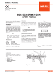
1
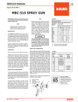
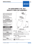
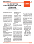
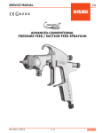
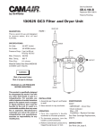
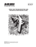
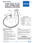
SERVICE MANUAL
EN
KB II TWO-QUART
PRESSURE CUPS
KB-555 ALUMINUM,
KB-545-SS STAINLESS STEEL
GOVERNMENT NSN NO. 4940-01-106-1415 = KB-555 CUP
IMPORTANT:
Read and follow all instructions and
SAFETY PRECAUTIONS before using this
equipment. Keep for future reference.
DESCRIPTION
All KB-II style cups are pressure regulated
and have a 2.4 quart (77 oz.) capacity. They
are designed to be attached to any manual
spray gun with air and material hose. The
cup may be carried in one hand using the
comfortable hand grip or left on the floor
while spraying. The KB-II's wide diameter and
low profile provides a low center of gravity
which increases stability and resists tipping.
Models KB-555 and KB-545-SS include a 0-30
psi gauge. KB II cups are supplied with KK5051 disposable cup liners (5 each) to reduce
clean up time and cleaning solvent.
Pressure cups provide a greater degree of
control over atomization air and material
pressure than obtainable through use of
suction feed equipment. Pressure cups also
enable user to apply heavy or more viscous
materials in small amounts where a 2 quart
capacity is sufficient for the job.
INSTALLATION
SPECIFICATIONS
Maximum regulated cup pressure - 50 psi (3.5 bar)
(fluid pressure)
Maximum air inlet pressure (to inlet on handle) - 125
psi (8.5 bar)
Hose Connections
Air - 1/4" NPS/BSPP (M)
Fluid - 3/8" NPS/BSPP (M)
Model Nos.
Height
Weight
Fluid Capacity KB-555
KB-545-SS
7-3/16"7-3/16"
3 lb. 14 oz.
4 lb. 5 oz.
77 oz. Maximum
1.
Connect fluid hose (A) to fluid inlet of
gun and outlet of cup (1) as shown. See
Figure 1.
2.
Connect atomization air hose (B) to air
inlet of gun and outlet of cup (2) as shown.
See Figure 1.
3.
Connect air supply hose (C) to inlet coupling (3) on cup handle. See Figure 1.
NOTE
Order hoses separately.
See "Accessories", page 4.
OPERATION
Risk of injury or equipment damage.
Air pressure to the cup must never
exceed 50 psi, (3.5 bar).
Mix and prepare the material to be sprayed
according to manufacturer's instructions.
Strain material through a 60 to 90 mesh screen
or equivalent before spraying. Place KK-5051
disposable liner into cup. Refer to instructions
provided with KK-5051.
Risk of injury. Cup is under pressure. Disconnect cup assembly
from air supply before installing or
removing lid assembly from cup
for filling or cleaning.
Wetted Parts:
Cup Aluminum
304 Electro Polished S.S.
Lid Gasket
SantopreneSantoprene
Check Valve Assy. Nylon
Nylon
Fluid Tube Assy.
Aluminum
304 S.S.
Passivated
Fluid Tube Nut
Nickel Plated 304 S.S.
BrassPassivated
Cup Lid
AluminumElectroless
Nickel Plated
Aluminum
Bleed Down Valve Nickel Plated 304 S.S.
BrassPassivated
KK-5051 LinersPolyethylene
SB-4-205-T (9/2014)
Air Inlet
CleanAir
Filter
Figure 1
1/8
C
A
B
2
3
1
EN
SAFETY PRECAUTIONS
This manual contains important information that ALL users should know and understand BEFORE using the equipment.
This information relates to USER SAFETY and PREVENTING EQUIPMENT PROBLEMS. To help you recognize this information, we use the following terms to draw your attention to certain equipment labels and portions of this manual. Pay special
attention to any label or information that is highlighted by one of these terms:
NOTE
Important information that
tells how to prevent damage
to equipment, or how to avoid
a situation that might cause
minor injury.
Information that you should
pay special attention to.
Important information to alert
you to a situation that might
cause serious injury if instructions are not followed.
CA PROP
The following hazards may occur during the normal use of this equipment.
Please read the following chart.
HAZARD
Spray
65
PROP 65 WARNING
WARNING: This product
contains chemicals known to
the State of California to cause
cancer and birth defects or
other reproductive harm.
CAUSE
SAFEGUARD
Solvent and coatings can be
highly flammable or combustible, especially when sprayed.
Adequate exhaust must be provided to keep air free
of accumulations of flammable vapors
Smoking must never be allowed in the spray area.
Fire extinguishing equipment must be present in the
spray area.
Solvent Spray
During cleaning and flushing, solvents can be forcefully
expelled from fluid and air passages. Some solvents can
cause eye injury.
Wear eye protection.
Inhaling Toxic
Substances
Certain materials may be
harmful if inhaled, or if there
is contact with the skin.
Follow the requirements of the Material Safety Data
Sheet supplied by your coating material manufacturer.
Adequate exhaust must be provided to keep the air free
of accumulations of toxic materials.
Use a mask or respirator whenever there is a chance of inhaling sprayed materials and its concentration. Equipment
must be as prescribed by an industrial hygienist or safety
expert, and be NIOSH approved.
Explosion HazardIncompatible Materials
KB-545-SS is stainless steel and
can be used with Halogenated
Hydrocarbons.
KB-555 is aluminum. Solvents
such as 1, 1, 1- Trichloroethane
and Methylene Chloride (sometimes called methyl chloride)
can chemically react with the
aluminum used in most spray
equipment, and these cups, to
produce an explosion hazard.
2/8
Read the label or data sheet for the material you intend
to spray.
Do not use any type of spray coating material containing
these solvents with KB-555.
Do not use these solvents for equipment cleaning or flushing with the KB-555.
If in doubt as to whether a material is compatible, contact
your material suppliers.
SB-4-205-T (9/2014)
EN
Description of Controls (Ref. Fig. 2, page 5)
Regulator Assembly (15) - Controls pressure
on material in cup.
Pressure Bleed Down Valve (6) - Allows air
to be bled from cup
To reduce pressure in cup, turn knob of regulator assembly counterclockwise. Bleed off
excess air by momentarily turning pressure
relief valve (6) counterclockwise. Readjust
pressure by turning knob of regulator (24)
assembly clockwise. Turning regulator all
the way out shuts off air supply to the cup.
NOTE
Turn pressure bleed valve (6) counterclockwise to vent air from the
cup; it is important to do this before
removing lid.
1.
2.
3.
4.
5.
6.
Place lid on cup. Grasp lid handle and
push down with one hand and tighten
retaining ring (1) with other hand.
Turn regulator knob (24) out (counterclockwise) until no spring pressure is felt.
Close pressure bleed valve (6) by turning
it in all the way clockwise.
Set air supply pressure at approximately
50-60 pounds at transformer.
Set material pressure at 10 pounds by
turning in regulator knob and reading the
gauge. Make sure fluid adjusting screw
on spray gun is open (turned out counterclockwise until first thread shows).
Test for amount of paint in relation to the
speed at which you want to spray. If too
much paint is coming out or atomized
particle size of paint is too large, follow
one of the procedures below.
A. Turn regulator knob counterclockwise until gauge shows lower pressure.
Bleed off excessive air in cup by turning
pressure bleed valve (6) counterclockwise.
B. Raise air pressure at transformer
until well defined atomized pattern of
paint is evident. This increases air pressure to spray gun while maintaining
same pressure in the cup.
Safety Valve, Regulator, Pressure Gauge
PREVENTIVE MAINTENANCE
The safety valve limits the maximum
air pressure. If the safety valve does
not work properly, over pressurization may occur and cause the cup
to rupture or explode. Occasionally
pull the ring on the safety valve and
make sure it operates freely. If the
valve is stuck or does not operate
smoothly, it must be replaced with a
valve having the same rating. Never
attempt to adjust or disassemble the
safety valve.
Always relieve pressure in cup before removing lid by turning bleed
valve out.
NOTE
Do not unthread the pressure bleed
valve (6) all the way, as it may fall
out and be lost.
Cleaning
Do not wash the lid assembly in a
gun washer. The safety valve, gauge
and regulator contain parts that will
be damaged. The cup only can be
washed in a gun washer.
Use of the KK-5051 disposable cup liner
will significantly reduce cleaning time and
sol-vent. Another accessory item, KK-5052
Adapter and Hose Kit, can also be used in
conjunction with the Solvent Saver™ to
save further time and solvent cleaning the
fluid passages of the tube, hose, and spray
gun. See Accessories page 4.
Grasp lid handle and push down with one
hand and turn the retaining ring (1) counterclockwise with the other hand. Pour out any
remaining material and add a suitable solvent.
Close cup lid as explained in "OPERATION"
section. Spray until clean solvent appears.
Cup and gun material passages should now
be clean. Empty any remaining solvent from
cup. Wipe cup with a solvent soaked cloth.
Check Valve
If contaminated, carefuly remove check valve
(12) from lid. Soak in suitable solvent. If damaged, replace. Do not torque to more than
10 in. lbs.
The safety valve (14) is factory set at approximately 55 lbs. Never disassemble. If damaged,
replace. Never submerge in solvents.
Regulator Disassembly
1. Pull the knob on the bonnet outward to
unlock regulator knob.
2. Turn the knob counterclockwise to stop.
3. Remove bonnet (24) by turning it coun
terclockwise. Use pliers if necessary.
4. Remove adjusting screw and nut, regu
lating spring, slip ring and diaphragm.
5. Use a wide blade screw driver and turn
valve seat (18) counterclockwise to re
move along with o-ring.
6. Carefully remove valve (17) and valve
spring (16).
Regulator Reassembly
1. Place valve spring (16) into center hole of
cast housing. Place valve (17) on the
spring (16).
2. Use a wide blade screw driver and
tighten valve seat and o-ring assembly
(18) to 4-6 in. lbs. torque.
3. Place diaphragm (19) on the valve seat.
Diaphragm tube must slide freely through
valve seat after valve seat is torqued
into the body.
4. Place slip ring (20) on inside shoulder of
bonnet (24).
5. Place adjusting screw (23), nut (22) and
regulating spring (21) into bonnet (24).
6. Tighten bonnet assembly (24) to 65-75 in.
lbs. torque.
TROUBLESHOOTING CHART
PROBLEM
CAUSE
CORRECTION
Excess pressure in cup.
Gauge (8) registering incorrectly
Safety valve (14) setting too high.
Valve spring (16) broken or distorted.
Diaphragm (19) damaged.
Leak at regulator valve (17 and 18).
Replace.
Replace.
Replace.
Replace.
Replace.
Insufficient pressure in cup.
Safety valve (14) leaking.
Check valve (12) stuck shut.
Gauge (8) registering incorrectly.
Leak at cup lid (11) threads.
Replace.
Clean or replace.
Replace.
Tighten cup or replace gasket (9) or slip ring (2).
SB-4-205-T (9/2014)
3/8
EN
PARTS LIST
Ref Replacement
No. Part No.
Description
1 KB-64
#2 KB-81-K5
*3 KB-74
4 ---
5P-MB-51
#6 KB-66
# KB-95
7 KB-70
KB-93
8 GA-355
#9 KB-80-K5
+10 MBD-11-K5
KB-97-K2
11 KB-422
KB-442
12 KB-432-K3
#13 KB-85-K5
14 TIA-4355
15 KB-428-1
•16 ---
•17 ---
•18 ---
•19 ---
•20 ---
•21 ---
•22 ---
•23 ---
•24 ---
+25 KB-60-K6
+26 ---
27 KK-4997
KK-4996
Ind.
Parts
Req.
Retaining Ring
1
Slip Ring (Kit of 5) 1
Handle - Secondary
1
Nut 5/16"-18 (purchase locally)
1
Adapter
2
Pressure Bleed Valve (For KB-555) 1
Pressure Bleed Valve (For KB-545-SS)
1
Lid w/handle (For KB-555)
1
Lid w/handle (For KB-545-SS)
1
Pressure Gauge 0-30 psi 1
Gasket (Kit of 5)
1
Locknut (For KB-555, Kit of 5)
1
Locknut (For KB-545-SS, Kit of 2) 1
2 qt. cup (For KB-555)
1
2 qt. cup (For KB-545-SS) 1
Check Valve (Kit of 3)
1
Gasket (Kit of 5)
1
Safety Valve
1
Regulator Kit
1
Valve Spring
1
Valve, PTFE
1
Valve Seat and O-Ring Assembly
1
Diaphragm, PTFE protected
1
Slip Ring
1
Regulator Spring
1
Nut
1
Adjusting Screw
1
Bonnet
1
Gasket (Kit of 6)
1
Fluid Tube Assembly
Fluid Tube Kit - (Aluminum For KB-555) 1
Fluid Tube Kit - (Stainless Steel
1
For KB-545-SS)
•These parts are included in the Regulator Kit
KB-428-1.
#Recommended Spare Parts and KB-428-1
Regulator Kit.
*A secondary handle (3) has been provided with
each cup. May be used for "Belt Hanging".
+These parts are included in Ref. No. 267,
Fluid Tube Kit.
✖Apply thread sealant (i.e. Loctite #242 medium
strength blue or equal) unto threads.
Figure 2
1
2
3
26
✖5
27
✖5
6
4
25
15
24
23
20 19
22 21
18 1716
7
14
12
8
13
9
10
27
11
4/8
SB-4-205-T (9/2014)
EN
ACCESSORIES
HAV-500 OR
HAV-501
Adjusting Valve
HARG-510 Air
Regulator
Spray Gun Lube
SSL-10
(HAV-501 SHOWN)
2oz.
Bottle
HAV-500 does not have
pressure gage. Use to
control air usage at gun.
192218 Scrubs®
Hand Cleaner Towels
(DeVilbiss Automotive Refinish)
29-3100 Scrubs® Hand
Cleaner Towels
(Finishing Brands – Binks)
Scrubs ® are
a pre-moistened hand
cleaner towel
for painters.
No water is
needed.
Use to maintain nearly
constant outlet pressure despite changes
in inlet pressure and
downstream flow.
42884-214-K5 3/8"
42884-215-K10 5/8"
Cleaning Brushes
Compatible with all paint
materials: contains no
silicone or petroleum
distillates to contaminate paint. MSDS available upon request.
WR-103
Wrench
Enables user
to control and
reduce air usage
at the gun. Ideal
for low pressure
spraying.
Contains all
necessary tip,
hose and nut
sizes used on
or with gun.
KK-5052 ADAPTER FITTING and
HOSE KIT
Allows flushing of cup tube, hose and gun using
SolventSaver™. Kit includes: HD-410 adapter
fitting and 2' hose assembly.
These brushes
are helpful in
cleaning threads
and recesses of
gun body.
Solvent
Saver™
KB II
KK-5051 Disposable
Cup Liner
Keeps cup and
lid isolated
from paint
reducing clean
up time and
solvent.
Kit includes:
20 liners
20 lids
3 rings
KB-4006, 6 ft. Hose Assembly - Includes 6 ft. air hose and 6 ft. fluid
hose and connections.
SB-4-205-T (9/2014)
P-H-5516
Air
Adjusting
Valve
5/8
EN
NOTES
6/8
SB-4-205-T (9/2014)
EN
NOTES
SB-4-205-T (9/2014)
7/8
EN
WARRANTY POLICY
DeVilbiss products are covered by Finishing Brands one year materials and workmanship limited warranty.
The use of any parts or accessories, from a source other than Finishing Brands, will void all warranties.
For specific warranty information please contact the closest Finishing Brands location listed below.
Finishing Brands reserves the right to modify equipment specifications without
prior notice. DeVilbiss, Ransburg, BGK, and Binks are registered trademarks of
Finishing Brands. ©2014 Finishing Brands. All rights reserved.
DeVilbiss is part of Finishing Brands, a global leader in innovative spray finishing
technologies. For technical assistance or to locate an authorized distributor,
contact one of our international sales and customer support locations below.
USA/Canada
Industrial Finishing
www.devilbiss.com
[email protected]
Tel:1-800-992-4657
Fax:1-888-246-5732
Mexico
Industrial Finishing
www.finishingbrands.com.mx
[email protected]
Tel: 011 52 55 5321 2300
Fax:011 52 55 5310 4790
United Kingdom
www.finishingbrands.eu
[email protected]
Tel: +44 (0)1202 571 111
Fax:+44 (0)1202 573 488
France
www.finishingbrands.eu
[email protected]
Tel: +33(0)475 75 27 00
Fax:+33(0)475 75 27 59
China
www.finishingbrands.com.cn
[email protected]
Tel: +8621-3373 0108
Fax:+8621-3373 0308
Japan
www.ransburg.co.jp
[email protected]
Tel: 081 45 785 6421
Fax:081 45 785 6517
Brazil
www.devilbiss.com.br
[email protected]
Tel: +55 11 5641 2776
Fax:55 11 5641 1256
Germany
www.finishingbrands.eu
[email protected]
Tel: +49 (0) 6074 403 1
Fax:+49 (0) 6074 403 281
Australia
www.finishingbrands.com.au
[email protected]
Tel: +61 (0) 2 8525 7555
Fax:+61 (0) 2 8525 7500
DeVilbiss Automotive Refinishing is part of Finishing Brands, a global
leader in innovative spray finishing technologies. For technical assistance
or to locate an authorized distributor, contact one of our sales and
customer support locations below.
USA/Canada
www.autorefinishdevilbiss.com
[email protected]
Toll Free Tel: 1-800-445-3988
Toll Free Fax:1-800-445-6643
8/8
Mexico
www.autorefinishdevilbiss.com.mx
Toll Free Tel: 1-888-835-6232 USA
SB-4-205-T (9/2014)