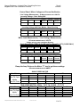
1
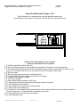
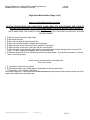
George Shrokman – Industrial Door Consulting Services
Megadoor 800-1000 Installation Checklist
Door #:
Location:
INSTALLATION CHECKLIST
One Motor Door
Job Name:
Door Number:
Location:
This installation check list is a continual improvement list, developed by service personnel in the field.
This is not a Megadoor Inc. document, only a guideline developed by George Shrokman to assist the
installer and dealer in a quality installation that will assist in extended life of the Megadoor system.
This does not replace the Megadoor Warranty sheets that must be signed by all installation personnel
upon the completion of the door. We do however suggest sending this worksheet along with the
Megadoor Warranty sheet as a detailed confirmation of the quality of the installation.
The check list may seem long, but depending on the door size and the quality of the installation, an
experienced installer can run through the list in 15 minutes. Very large doors may take up to an hour,
depending on the time it takes to move the man lift around.
For the safety of all concerned, we suggest using a boom lift, NOT A SCISSOR LIFT OR SCAFFOLD
when checking the operation. Take note that the Megadoor is a hoist system intended to pick up a
tremendous amount of weight quickly. The bottom beam or curtain will only stop moving upward
when a stop button is pressed and held, or the power is turned off. The lift must be clear of the
moving curtain. When you are in the air checking the door, safety personnel should be positioned
near the power disconnect to shut the system down in case of an emergency.
Since this is a continual improvement list, please forward any comments or suggestions so we can
incorporate them into this procedure.
Thank you for the opportunity to work with you.
George A. Shrokman, Jr.
email: [email protected].
C:\Megadoor\SERVICE MANUAL\Installation Checklist One Motor 1000.odt
2/18/2007 10:51:48 AM
1 of 11
George Shrokman – Industrial Door Consulting Services
Megadoor 800-1000 Installation Checklist
Door #:
Location:
General Information
Customer :
Door Serial Number:
inspection Date:
Location Description _____________________
Total Width Dimension _____’ ____” Clear Width Dimension ____’ ____”
Total Height Dimension _____’_____” Clear Height Dimension _____’ _____”
General Information
These are items of general information that is used to document that the proper dimensions have been used
during the door installation.
Checking Total Width Dimensions
1. [] Total Width (TW) 6” above floor level. Total width measurement ______’ ________”.
2. [] Total Width ¼ up side jamb ( _______’ height) Total width measurement ______’ ________”.
3. [] Total Width ½ up side jamb (________’ height) Total width measurement ______’ ________”.
4. [] Total Width ¾ up side jamb (________’ height) Total width measurement ______’ ________”.
5. [] Total Width at top of header box. Total width measurement ______’ ________”.
Checking Total Height Dimensions
1. [] Measure Total Height from the bottom of the mounting steel to the top of the header box.
Left Side ________’ ________”.
Right Side ________’ ________”
Checking Clear Height Dimensions
1. [] Measure the Opening Height from the floor to the bottom of the opening lintel.
Left Side ________’ ________”.
Right Side ________’ ________”
Installation Questions.
1. Was the side jambs and header box leveled via: [] Transit [] Hydro Level [] Don’t Know
2. How were the side jambs checked for “plumb”: [] Transit [] Plumb-bob [] Sight
3. Check the door steel and door for squareness – perform a criss-cross measurement.
•
Dimension from left hand top to right hand bottom. ________’ ________”
•
Dimension from right hand top to left hand bottom. ________’ ________”
C:\Megadoor\SERVICE MANUAL\Installation Checklist One Motor 1000.odt
2/18/2007 10:51:48 AM
2 of 11
George Shrokman – Industrial Door Consulting Services
Megadoor 800-1000 Installation Checklist
Door #:
Location:
Checking header box for vertical alignment.
Measure from the face of the side jamb to the top and bottom of the header box. The dimension should be the
same at the top and the bottom. (see illustration below). Front of header box must be plumb!
Dimension must
be equal
Top Dimension
_____________
Bottom
Dimension
_____________
Left Hand Box shown above
Dimension must be equal
Top
Dimension
__________
Bottom
Dimension
________
Right Hand Box shown above
Check for header twist between the left and right side. FRONT OF HEADER BOX MUST BE PLUMB!
C:\Megadoor\SERVICE MANUAL\Installation Checklist One Motor 1000.odt
2/18/2007 10:51:48 AM
3 of 11
George Shrokman – Industrial Door Consulting Services
Megadoor 800-1000 Installation Checklist
Door #:
Location:
Left Hand Machine Box (Page 1 or 2)
These Items are to be checked when up at the left side machine box.
Tools Required: Tape measure, bullet level, torks 30, Allen m5, small screw driver.
CLS
3LS
1LS
5LS
LB1
LIMI
BOX
MOTOR CONNECTIONS
LIMIT SWITCH CONNECTION TERMINALS
Items to check with limit box cover removed.
• Items to check with door not in motion.
1. [] LB1 Mounting Bolts Installed (Qty of 4)
2. [] Belt wound on drum properly (belt wraps to the top of the drum from the left hand side)
3. [] Top mounting bolt located above the belt is installed so the bolt head is on the bottom, and the nut is on
the top. (if it is installed with the nut on the bottom, the bolt will eventually rub the belt).
4. [] Belt not twisted.
5. [] Belt drum bolt is tight on motor shaft.
6. [] U-bracket on limit plunger straight (not bent into a “w” shape)
7. [] U-bracket Roller Square with Belt
8. [] Top Plunger straight.
9. [] Open plunger (bottom plunger) moves freely.
10. [] Open plunger (bottom plunger) spring not rubbing aluminum top beam.
11. [] Limit switches mounted square. (note: 1LS can have a slight twist when a two speed motor is used..)
12. [] Check tightness of all wires in the terminal blocks
13. [] Electrical wires not rubbing belt drum or belt.
14. [] Header box and side guide align (check alignment of the square belt feed hole in the header box and the
top of the side guide. The guide should be centered with the hole.
15. [] Bolts attaching curtain to header box installed.
16. [] Is the motor / gearbox assembly level?
C:\Megadoor\SERVICE MANUAL\Installation Checklist One Motor 1000.odt
2/18/2007 10:51:48 AM
4 of 11
George Shrokman – Industrial Door Consulting Services
Megadoor 800-1000 Installation Checklist
Door #:
Location:
Left Hand Machine Box (Page 2 or 2)
Items to check while the door is running.
CAUTION: MOVING DOOR CAN CAUSE DEATH. MAKE SURE LIFTS AND PERSONEL ARE CLEAR OF
MOVING DOOR CURTAIN. KEEP FINGERS AND HANDS CLEAR OF MOVING PARTS INSIDE OF
MOTOR BOX
.
NOTE: MAKE SURE THE HINGED COVER IS NOT CAUGHT BY THE DOOR CURTAIN AS THE DOOR
MOVES UPWARD
1. [] Belt running in the center of the rollers.
2. [] Belt clears all wires as drum diameter changes.
3. [] Belt runs smoothly through bottom of box.
4. [] Belt runs smoothly through U-bracket and top plunger
5. [] When the door is fully closed, 2LS trips, and 1LS is not tripped.
6. [] When the door is fully open, 5LS trips, and 1LS is not tripped.
7. [] When the door stops at the fully open position, the open plunger (bottom plunger) does not touch 1LS
roller. If it does, explain what happens after it touches the roller.
8. [] Manually depress 1LS, have someone press the open/close button. Door should not operate. If it does,
door is not wired properly.
Items to check externally while on the left side..
Door not in motion.
1. [] Two bolts in each limit cover (door).
2. [] Extra header box support installed at bottom of left motor box (welded between header box & guide steel)
3. [] Vent plug installed in gear case.
4. [] Brake release rod clipped on to motor bolt.
5. [] Crank limit switch sets and resets.
6. [] Crank arm – bolt that keeps arm from vibrating out of position installed.
7. [] Crank arm clears back of motor by ¼” to ½”.
8. [] SR Relay (round plastic piece on the bottom of the motor junction box) tight to case (hand tight)
9. [] Dimension between the outside edge of the header box and the guide steel
(System 800 – 5mm, System 1000-0mm) ____________
10. [] Door curtain alignment – Dimension between the side mounting steel and the batten strip on the top rail
of the curtain that is attached to the header box.
C:\Megadoor\SERVICE MANUAL\Installation Checklist One Motor 1000.odt
2/18/2007 10:51:48 AM
5 of 11
George Shrokman – Industrial Door Consulting Services
Megadoor 800-1000 Installation Checklist
Door #:
Location:
Right Hand Machine Box (Page 1 of 2)
These Items are to be checked when up at the right side machine box.
Tools Required: Tape measure, bullet level, torks 30, Allen m5, small screw driver.
LB2
LIMIT
BOX
4LS
2LS
6LS
Items to check with limit box cover removed.
• Items to check with door not in motion.
1. [] LB2 Mounting Bolts Installed (Qty of 4)
2. [] Belt over pulleys properly (on top of left pulley, through limit “U” bracket, on top of right pulley)
3. [] Top mounting bolt located above the belt is installed so the bolt head is on the bottom, and the nut is on
the top. (if it is installed with the nut on the bottom, the bolt will eventually rub the belt).
4. [] Belt not twisted.
5. [] Belt is through upper square hole in left hand bracket.
6. [] U-bracket on limit plunger straight (not bent into a “w” shape)
7. [] U-bracket Roller Square with Belt
8. [] Top Plunger straight.
9. [] Open plunger (bottom plunger) moves freely.
10. [] Open plunger (bottom plunger) spring not rubbing aluminum top beam.
11. [] Limit switches mounted square.
12. [] Check tightness of all wires in the terminal blocks
13. [] Electrical wires not rubbing belt.
14. [] Header box and side guide align (check alignment of the square belt feed hole in the header box and the
top of the side guide. The guide should be centered with the hole.
15. [] Bolts attaching curtain to header box installed.
16. [] Is the assembly level?
C:\Megadoor\SERVICE MANUAL\Installation Checklist One Motor 1000.odt
2/18/2007 10:51:48 AM
6 of 11
George Shrokman – Industrial Door Consulting Services
Megadoor 800-1000 Installation Checklist
Door #:
Location:
Right Hand Machine Box (Page 2 of 2)
Items to check while the door is running.
CAUTION: MOVING DOOR CAN CAUSE DEATH. MAKE SURE LIFTS AND PERSONEL ARE CLEAR OF
MOVING DOOR CURTAIN. KEEP FINGERS AND HANDS CLEAR OF MOVING PARTS INSIDE OF
MOTOR BOX.
NOTE: MAKE SURE THE HINGED COVER IS NOT CAUGHT BY THE DOOR CURTAIN AS THE DOOR
MOVES UPWARD.
1. [] Belt running in the center of the rollers.
2. [] Belt clears all wires.
3. [] Belt runs smoothly through bottom of box.
4. [] Belt runs smoothly through U-bracket and top plunger
5. [] When the door is fully closed, 4LS trips, and 2LS is not tripped.
6. [] When the door is fully open, 6LS trips, and 2LS is not tripped.
7. [] When the door stops at the fully open position, the open plunger (bottom plunger) does not touch 2LS
roller. If it does, explain what happens after it touches the roller.
8. [] Manually depress 2LS, have someone press the open/close button. Door should not operate. If it does,
door is not wired properly.
Items to check externally while on the right side..
Door not in motion.
1. [] Two bolts in each limit cover (door).
2. [] Dimension between the outside edge of the header box and the guide steel
(System 800 – 5mm, System 1000-0mm) ____________
Door curtain alignment – Dimension between the side mounting steel and the batten strip on the top rail of the
curtain that is attached to the header box.
C:\Megadoor\SERVICE MANUAL\Installation Checklist One Motor 1000.odt
2/18/2007 10:51:48 AM
7 of 11
George Shrokman – Industrial Door Consulting Services
Megadoor 800-1000 Installation Checklist
Door #:
Location:
Check the centerline alignment of the door guides.
The centerline of the guides at the
bottom of the door can be off by ____”
Centerline
Centerline
The guides are centered perfectly at the header box, and must be
centered perfectly at the bottom. Make sure the guides are aligned across
the opening as shown. There is a ___” tolerance, depending on the
opening width. The guides must be aligned to provide correct clearance
between the guide blocks and the guide itself.
A laser level rotated to the vertical position can be used to check the centerline on the guides.
Check to make sure the face of the guides and mounting steel are parallel facing each side.
There are many ways to verify
that the steel and guides are
square to each other. This
straight edge method is just
one. We are concerned that
the throat of the guide is
square, so the end blocks do
not wear unevenly.
Clear Width Dimension
Straight
Edge
The guide faces must be square
to each other.
This can be checked by
clamping straight edges (3’ to 4’
long) to the face of the guides
and checking the CW (Clear
Width) dimensions at various
points.
Straight
Edge
We do not provide a tolerance
for this being out of square.
Clear Width Dimension
C:\Megadoor\SERVICE MANUAL\Installation Checklist One Motor 1000.odt
2/18/2007 10:51:48 AM
8 of 11
George Shrokman – Industrial Door Consulting Services
Megadoor 800-1000 Installation Checklist
Door #:
Location:
Door Curtain
1. [] All clamp strips are straight on the ends (not bent).
Right Inside [] ok Left Inside [] ok Right Outside [] ok Left Outside [] ok
2. [] Bottom batten strips installed properly. (see figure below)
Right Inside [] ok Left Inside [] ok Right Outside [] ok Left Outside [] ok
Ends of upper batten strip should
be even with end of bottom
batten strip. This is an “ok”
condition.
These strips are not installed
correctly.
3. [] Protective studs installed in the clamp strip ends on the bottom beam.
Left Inside [] Yes [] No
Right Inside [] Yes [] No
Left Outside [] Yes [] No
Right Outside [] Yes [] No
4. [] With the door fully closed the curtain is fully stretched, and the reversing door edge is ½” to ¾” above the
finished floor. There is adequate clearance under the edge so it does not trip when fully closed.
Guide Rails
1. [] All bolts installed in guides
2. [] Bolts have been properly torqued
3. [] Throat of guide measures correctly
4. [] Guides aligned at splice points
5. [] Guides plumb and straight
6. [] Side guide steel gussets installed
7. [] Bottom of guide supported where necessary
8. [] Guides installed square to opening
9. [] Guides are installed plumb.
10. [] Guide dimension from wall correct.
11. [] Edges of guides (joints) dressed and burr free.
C:\Megadoor\SERVICE MANUAL\Installation Checklist One Motor 1000.odt
2/18/2007 10:51:48 AM
9 of 11
George Shrokman – Industrial Door Consulting Services
Megadoor 800-1000 Installation Checklist
Door #:
Location:
MISC ITEMS
1. [] Reversing edge operates properly.
2. [] Photo-eyes operate.
3. [] Is the door making any strange sounds?
____________________________________________________
____________________________________________________
____________________________________________________
____________________________________________________
____________________________________________________
___________________________________________________
4. [] What other items should be noted.
____________________________________________________
____________________________________________________
____________________________________________________
____________________________________________________
Dimensions and Torque
Header Box
Nuts on bolts attaching top of curtain to the header box. Nut Size _____ Torque _____
Guides
Guide Bolt Torque: Bolt Size ______ Torque _____
Guide opening width when bolts properly tightened. ______” ________mm
C:\Megadoor\SERVICE MANUAL\Installation Checklist One Motor 1000.odt
2/18/2007 10:51:48 AM
10 of 11
George Shrokman – Industrial Door Consulting Services
Megadoor 800-1000 Installation Checklist
Door #:
Location:
Control Panel / Motor Voltage and Current Verification
Line Voltage Measurement All Measurements are in VOLTS
Incoming Voltage – Door Sitting Still
Incoming Voltage Measured at the Bottom of the Disconnect
Leg A to B Leg B to C Leg A to C
Leg A to
Ground
Leg B to
Ground
Leg C to
Ground
Incoming Voltage with Door Motion - Motor Running
Incoming Voltage Measured at the Bottom of the Disconnect
Leg A to B Leg B to C Leg A to C
Leg A to
Ground
Leg B to
Ground
Leg C to
Ground
Motor Lead Measurement ( T Lead Voltage Measurement )
All measurements are in VOLTS
Voltage going to motor with Motor Running
Single Speed Motor (OPEN & CLOSE) and Two Speed T1 T2 T3 (CLOSE ONLY)
Voltage Measured at Terminal Blocks in Control Panel
T1 to T2
T2 to T3
T1 to T3
T1 to
Ground
T2 to
Ground
T3 to
Ground
Two Speed Motor T4 T5 T6 (OPEN ONLY)
Voltage Measured at Terminal Blocks in Control Panel
T4 to T5 T5 to T6 T4 to T6
T4 to
T5 to
T6 to
Ground Ground Ground
Clamp the Amp Probe on the Motor “T” lead to get these readings
All measurements are in AMPS.
Motor T lead
Reading Position
LT1
Raise
SINGLE SPEED MOTOR
LT2
Lower
Raise
LT3
Lower
Raise
Lower
Near Full Open
Middle
Near Full Close
TWO SPEED MOTOR: OPEN – T4 T5 T6 CLOSE – T1 T2 T3
Motor T lead
T4
T1
T5
T2
T6
T3
Reading Position
Raise
Lower
Raise
Lower
Raise
Lower
Near Full Open
Middle
Near Full Close
C:\Megadoor\SERVICE MANUAL\Installation Checklist One Motor 1000.odt
2/18/2007 10:51:48 AM
11 of 11