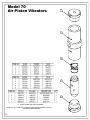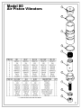
1
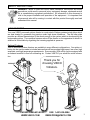
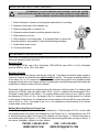
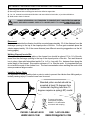
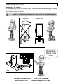
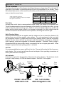
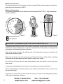
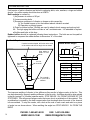
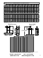
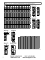
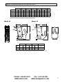
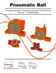
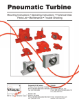
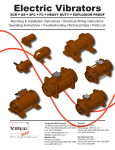
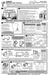
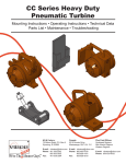
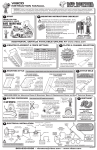
Pneumatic Piston Mounting Instructions • Operating Instructions • Technical Data Parts List • Troubleshooting Corporate HQ & Factory: 75 Stilson Road Wyoming, RI 02898 Phone: 800 633-0032 (401) 539-2392 Fax: (401) 539-2584 E-mail: [email protected] Website: www.vibco.com Canada: 2215 Dunwin Drive Mississauga, ONT L5L 1X1 Phone: 800 465-9709 (905) 828-4191 Fax: (905) 828-5015 Thank you for choosing VIBCO, Inc. for your vibration needs. You are now the owner of the finest pneumatic piston vibrator available today, backed by complete manufacturer confidence in its quality and dependability. For reference, please complete the information below about your new VIBCO vibrator. Model Number: ____________________ Date of Purchase: ____________________ TABLE OF CONTENTS Safety Instructions & How It Works .............................................................................................3 Mounting Instructions: Checklist & Notes ..............................................................................4-5 Mounting Suggestions by Bin Type .........................................................................................6-9 Custom Mounting .......................................................................................................................9 Vibrator Installation and Pneumatic Hook-up ..........................................................................10-13 Operating Instructions ...............................................................................................................12 Troubleshooting .........................................................................................................................14 Technical Data and Dimensions Model 50,55, & LI ...........................................................................................................15 Model 10, 30, 40, 70, 80 .................................................................................................16 Model 42,44.........................................................................................................................17 Parts List and Breakdown Model 50 .........................................................................................................................18 Model 55 .........................................................................................................................19 Model 10 .........................................................................................................................20 Model 30 .........................................................................................................................21 Model 40 .........................................................................................................................22 Model 42 .........................................................................................................................23 Model 44-3 .........................................................................................................................24 Model 44-3L.........................................................................................................................25 Model 70.........................................................................................................................26 Model 80 .........................................................................................................................27 Warranty & General Information ................................................................................................28 2 PHONE: 1-800-633-0032 FAX: 1-401-539-2584 WWW.VIBCO.COM [email protected] SAFETY INSTRUCTIONS WARNING: Failure to read and follow these installation instructions and safety precautions could result in personal injury, equipment damage, shortened service life or unsatisfactory equipment performance. All information in this document is vital to the proper installation and operation of the equipment. It is important that all personnel who will be coming in contact with this product thoroughly read and understand this manual. HOW IT WORKS Your new VIBCO pneumatic piston vibrator is constructed of fatigue-resistant steel alloys which are heat treated to guarantee long service under high stress conditions. The flat base plate provides an efficient transmission of the shock energy to the system which is developed by the reciprocating piston. The repetitive hammer action of the vibrator on the apparatus to which it is attached is controllable by regulating the incoming applied air pressure. Optional Features VIBCO pneumatic piston vibrators are available in many different configurations. Your piston vibrator can be custom made to include features that will accomodate high impact, low noise, high amplitude, and high temperature requirements. Some models (-EM suffix) can be equipped with an exhaust manifold to lead off exhausting air. Contact VIBCO if you would like more information. AIR INLET Thank you for choosing VIBCO Vibrators. PHONE: 1-800-633-0032 FAX: 1-401-539-2584 WWW.VIBCO.COM [email protected] 3 MOUNTING INSTRUCTIONS CHECKLIST The warranty is void if vibrator is not properly installed. During installation follow and check off the following steps and your vibrator should provide you with years of trouble-free service. ̸̸ 1. Select thickness of vibrator mounting plate and method of mounting. ̸̸ 2. Determine the length of the channel iron. ̸̸ 3. Weld mounting plate to channel iron. ̸̸ 4. Determine where vibrator should be placed on the bin. ̸̸ 5. Weld channel iron to bin. ̸̸ 6. Place vibrator on mounting plate. It is important that you check the mounting plate for any warping. Follow bolt tightening procedure. ̸̸ 7. Install safety chain or wire. ̸̸ 8. Connect pneumatics. NOTES ABOUT INSTALLATION If you have any questions consult the Mounting Instructions section of this manual or call VIBCO Technical Support at (800) 633-0032. Mounting Plate For force up to 100 lbs. use a 1/4 in. thick plate, 100 to 500 lbs. use a 3/8 in. to 1/2 in. thick plate and over 500 lbs. use a 1/2 in. thick plate. Mounting Channel Never place the vibrator directly onto the skin of the bin. It should be mounted to either a plate or a piece of channel iron that has been stitch welded to the bin. The proper mounting method is to use either 3 in. or 4 in. channel iron. This will help to stiffen the structure to be vibrated as well as spread the vibration over a larger surface, increasing the overall efficiency and diminishing the possibilities of fatigue cracks in the bin material. The length of the channel iron is determined by the thickness of the bin plate. For vibrators with a force up to 500 lbs. and a bin plate under 3/16 in., the 4 in. channel iron should extend 18 to 36 inches on both sides of the vibrator. For smaller vibrators with a force of up to 100 lbs. and a bin thickness of 3/16 in. to 1/4 in., the length of the 3 in. channel iron should extend 3 to 4 inches on both sides of the vibrator. For vibrators with a force between 100 and 500 lbs. and a bin thickness of 3/8 in. to 1/2 in., the length of the 3 in. or 4 in.channel iron should extend 6 to 8 inches on both sides of the vibrator. Welding Mounting Plate to Channel Iron Weld the mounting plate to the middle of the channel iron. If the bin plate is 3/16 in. or less, weld the mounting plate to the back of the channel iron (see Figure 3 or 4). If the bin plate is over 3/16 in. weld the mounting plate to the legs of the channel iron (see Figure 1). Drill and tap holes or use studded plate (see Figure 1 or 5). Make sure the mounting plate does not warp or distort. If this occurs, straighten, replace it or shim vibrator. 4 PHONE: 1-800-633-0032 FAX: 1-401-539-2584 WWW.VIBCO.COM [email protected] Different Suggestions for Mounting channel 1) Mounting plate welded to legs of channel iron. 2) Mounting channel with mounting plate and holes drilled or tapped thru. 3) 3 or 4 in. channel iron with holes drilled thru and nuts welded on back side, or just holes drilled thru. 4) Weld studs to back of channel. Always stop welds 1 in. from ends to prevent heat concentration and bin crack. Skip weld channel: weld 2 to 3 inches, skip 1 to 2 inches and repeat until securely mounted. 1 2a 2b 3a 3b 4a 4b Placement For coarse materials the vibrator should be mounted approximately 1/3 of the distance from the discharge opening to the top of the sloped portion of the bin. For fine grain materials place the vibrator approximately 1/4 of the same distance (see different mounting suggestions on the following pages). Welding Channel Iron to Bin Where possible, the mounting plate or the channel iron should be placed 1/3 to 1/4 of the distance from the discharge opening to the top of the sloped portion of the bin. Tact weld channel iron in place, then weld intermittent welds 3 in. to 6 in. long with 3 in. between them along the entire length of the channel. Stop weld a minimum of 1 in. from the ends. It is important that you do not weld the ends of the channel iron. The heat concentration when welding the ends could cause premature fatigue cracks. Installing Safety Chain It is important to install a safety chain or wire in order to prevent the vibrator from falling and potentially causing injury if it comes loose from its mount. Standard piston models should be mounted at least 15 degrees from horizontal. Anything less than 15 degrees requires a spring(-SP) model. 15° To ensure a fast start of the piston everytime. Models 1-1/4” and smaller come stock with a spring. PHONE: 1-800-633-0032 FAX: 1-401-539-2584 WWW.VIBCO.COM [email protected] 5 MOUNTING SUGGESTIONS Conical Bin 1/2 Rectangular Bin Rectangular Bin Two Vibrators On A Single Bin L L L L1 L2 For course material mount vibrator 1/3 of the length (L) from the discharge opening. For fine material mount vibrator 1/4 of the length (L) from the discharge opening. For large bins mount two units 180° opposite 1/4 of the length (L1) and 1/2 of the length (L2) from the discharge opening. One Vibrator For A Double Bin 4 IN. CHANNEL 3/8 IN. GUSSETS 4 IN. SQUARE TUBING MOUNTING PLATE Bin With Stiffeners 6 VIBRATOR Angle Iron Stiffeners Instead of Channel Iron Thin Skinned Bin Corner Mount PHONE: 1-800-633-0032 FAX: 1-401-539-2584 WWW.VIBCO.COM [email protected] Sheet Metal Bin Belt Conveyor and Standard Bin DRILL HOLES IN ANGLE TO MATCH BOLT PATTERN BOLT TO BIN L 1/3 L WELD BOTH SIDES OF ANGLE IRON ANGLE IRON FEET 3/8” MOUNTING PLATE Long Bin W 1/3 W L 1/3 L Belt Conveyors Belt conveyor feeds from the front. Vibrator should be placed 1/3 from the front. If 2 vibrators are used, place second one directly opposite 1/3 from the back. Do not operate back vibrator until bin is empty in front and the front vibrator has turned off. For more details, consult VIBCO. W FLO L 1/3 L W 1/3 W L 1/3 L Screw Conveyors Feeds from back. Vibrator should be placed 1/3 from the back. If 2 vibrators are used, place 2nd one directly opposite 1/3 from the front. Do not operate front vibrator until bin is empty in back and the back vibrator has turned off. For more details, consult VIBCO. PHONE: 1-800-633-0032 FAX: 1-401-539-2584 WWW.VIBCO.COM [email protected] 7 Heat Mounts for Insulated Bins Containing High Temperature Materials: When materials in the bin have a temperature over 150oF, it is advisable to use a “heat” mount to prevent excessive heat from reaching the vibrator and causing overload or bearing failure. Also, ask for “high” temperature grease in vibrator bearing. Consult VIBCO for vibrator size. BIN 2-1/2 to 3ft 2ft 1-1/2ft 10 IN. CHANNEL 1ft L 450°-500°F 8 IN. 300°F 6 IN. 200°F 4 IN. 140°F 1/3 L 3” OR 4” CHANNEL IRON CHANNEL IRON GUSSETS L GUSSET PLATE 4” PIPE, I-BEAM OR TUBE VIBRATOR 1/4 L PLATE RUBBER PLATE PLATE SPACER RUBBER Concrete Bin: Mount steel plate on inside of bin so that the vibrator sits 1/3 up bin side. Isolate the plate from the concrete by using rubber vibration shock absorbers. Consult VIBCO for detailed drawings. 8 Wood Bin: Use steel plate on inside and bolt to outside mounting channel. PHONE: 1-800-633-0032 FAX: 1-401-539-2584 WWW.VIBCO.COM [email protected] CHUTES In order to successfully move material in a chute, the “angle of repose” of the material has to be known. It can be found in most handbooks or can easily be measured by pouring a cup of the material on a table. The angle between the table and the cone the material makes is the “angle of repose”. To move the material in the chute, it should be inclined no less than 1/2 of the “angle of repose” If this cannot be obtained, a feeder is necessary to move the material. For optimum performance follow these guidelines: • Force (impact) needed on vibrator is equal to weight of chute + vibrator + max material in chute. • Chutes must have an inclination of at least 10o for vibrators to be able to move the material. If inclination is less the chute has to be made into a feeder. Contact VIBCO for selecting the proper size vibrator or ask for the bulletin covering chutes. • Chutes up to 6 ft. are generally handled by one vibrator mounted approximately 1/3 from the discharge. • On chutes over 6 ft. long, two vibrators are needed, one should be placed 18 - 24 inches from the discharge. The other approximately in the middle. Since chutes are very sensitive to vibration, provision should be made to move the lower vibrator 6 inches in either direction. This could mean the difference between moving the material or not moving it. L = Up to 6 FT. 1/3 L CUSTOM MOUNTING APPLICATIONS For custom mounting applications E-mail [email protected] Call 1-800-633-0032 or PHONE: 1-800-633-0032 FAX: 1-401-539-2584 WWW.VIBCO.COM [email protected] 9 VIBRATOR INSTALLATION Installation of the Vibrator It is now time to put the VIBCO vibrator in place. Make sure that it is secured tightly. Retighten the bolts after the first 10 to 15 minutes of operation and check them periodically to maintain proper tightness (figures 1 and 2). Damage to the bin and the vibrator can occur if not mounted securely. Angle Iron Channel Iron Figure 1 JUNE JULY Remember: Check those bolts! AUGUST Figure 2 10 PHONE: 1-800-633-0032 FAX: 1-401-539-2584 WWW.VIBCO.COM [email protected] Pneumatic Hook-up Air Line To Vibrator The hose to the inlet port of the vibrator should have the same or larger hose I.D. as the inlet I.D. (pipe size) of the vibrator to minimize pressure loss from the compressor to the vibrator. Check the technical data section of this manual, and find the specifications that meet your model to ensure you have the correct sizes. TO DETERMINE CORRECT AIR HOSE SIZE** * F=filter R=regulator L=lubricator ** These specs for installation of single unit; for multiple units, adjust to maintain CFM PISTON DIAMETER MIN AIR HOSE DIA MIN FRL* THREAD DIA CFM 5/8” to 1-1/4” 1/4” 1/4” 4 - 10 1-1/4” to 1-1/2” 3/8” 3/8” 11 - 20 2L” & UP 1/2” 1/2” 21 - 50 Flow Valve A simple flow control valve is recommended to allow “tuning” the vibrator to the desired force. The air flow determines the force and frequency of the vibrator. By throttling the air flow, you can “find” the desired material discharge rate. Watch for and avoid speeds (frequency) at which the binwall and the vibrator shake violently. An increase or decrease of air flow usually stops the excessive movement and will smooth out the operation, assuming the mount is rigid. Quick Opening Valves Recommended between the air regulator and the vibrator so the air enters the vibrator at full starting force even with low regulator valve settings. The only requirement is that you install the air regulator at least 12 inches away from the quick opening valve so that the air pressure between the two valves will build up enough to yield the necessary starting force. Solenoid (quick opening) valves are suggested for automatic operations. Automatic Timed Cycling is programmed with the timer usually directly connected to the bin or hopper gate switch. When the gate is opened the timed cycling system is activated. Air Filter It is recommended that you use an air filter in the line. Clean air will prolong the life of any pneumatic vibrator. Dirty or moist air will harm the unit and impair it from operating at maximum efficiency and lowest air consumption. Air Lubricator Lubricaton is required for the operation of the pneumatic piston vibrators. The lubricator should be set at 1 drop for every 10 CFM the vibrator requires. Use SAE-10 oil or lighter. To Vibrator To Gate To Control Switch Solenoid Valve Timer Air Regulator Air Lubricator Flow Valve Air Filter PHONE: 1-800-633-0032 FAX: 1-401-539-2584 WWW.VIBCO.COM [email protected] 11 Maximum Air Pressure The operating pressure of the vibrator should not exceed 80 psi unless specially contructed for higher pressure standards by VIBCO. Maximum Temperature The operating temperature of the vibrator should not exceed 200oF (93oC). High temperature units are available. 200°F Not Recommended Figure 3 93°C Figure 4 Safe Operation Important considerations for long operating life Contaminated air will shorten the life of the vibrator considerably, and will clog the critical clearance between the cylinder and the piston. It will also increase the wear of the piston, increasing the air consumption and diminishing vibrator efficiency. Water in the air line will reduce the effectiveness of the lubrication necessary to make the unit operate and lubricate properly. Water, dirt and air line rust at air pressures over 80 psi will create a sludge similar to grinding compound and will wear down the piston and the cylinder very quickly. No oil in the air will cause the piston and cylinder walls to wear down rapidly, in some cases less than 8 hours. In extremely cold applications it is advised to mix antifreeze or kerosene with the oil. Inject a small quantity of kerosene directly into the vibrator occasionally in order to clean out any accumulated sludge. Air pressure in excess of 80 psi will increase the velocity of the piston, diminishing the protective oil film and increasing the unit wear. 12 PHONE: 1-800-633-0032 FAX: 1-401-539-2584 WWW.VIBCO.COM [email protected] Operating INSTALLATION To Obtain Maximum Performance It is not necessary to operate the vibrator at its maximum capacity to obtain maximum performance. Air regulators, timers, etc. should be used to tune the vibrator for optimum performance and ensure longer life. Continuous vs. Intermittent Operation For bulk material bin applications, the vibrator should be used to reduce the material friction and increase flow, not as a feeder. Once the friction of the particles is reduced, gravity flow takes over and the vibrator should then be turned off for several reasons: Economy Most vibrators are run 60% to 80% longer than they should. Short bursts of vibration are usually more effective than operating continuously. Experience has shown that for most applications, short bursts of 10 to 30 seconds for every 1 to 5 minutes of discharge are more effective and efficient. Life of the Unit The life of the vibrator will be determined by the length of operation and the cleanliness of the air supply. Guaranteed Success of the Application The vibrator can only furnish material to the discharge area. If more is furnished than conveyed, the remaining material will pack inside the bin. We suggest the vibrators only run when the bin gates or doors are open, or when material flow is needed. PHONE: 1-800-633-0032 FAX: 1-401-539-2584 WWW.VIBCO.COM [email protected] 13 Troubleshooting Field repairs of piston vibrators are limited to replacing bolts, nuts, washers, o-rings and rubber shocks. Any other repairs should be done at VIBCO. Bolt breakage is caused by: 1) Air pressure in excess of 80 psi. 2) Loose mounting bolts. 3) Excessive movement of vibrator on hopper or bin caused by: A) Too flexible hopper or bin that cannot absorb vibration created. B) Operation on empty hopper. 4) Dried up rubber buffers. Buffers are used to absorb shock energy and prolong bolt life. Through aging the buffers will take a “set” and deteriorate. It is advisable to replace all buffers and bolts at this time. Rubber buffers should be replaced following these instructions. The bolts are not torqued but tightened to compress the rubber buffers to dimension “A” of the chart. Bin Crack Repair If cracks have developed, drill holes at the ends of the cracks and weld on angle iron as shown Rubber Buffer Height Stop welds at least 1 in. from ends Mounting plate for vibrator 3 or 4 in. channel Do not weld 1 in. from end of stiffener MODEL “A” (IN.) 50-1 3/16 50-1-1/4 3/8 50-1-1/2 1/2 50-2 1/2 50-2L 5/8 50-3 11/16 50-3L 11/16 The improper welding of vibrator to bin stiffeners often results in fatigue cracks in the bin. This can be prevented by properly welding stiffeners to the bin side. A stiffener should be skip welded to the bin leaving 3 to 4 inches between welds. STOP WELDS 1 IN. FROM THE ENDS OF THE STIFFENER. This will prevent fatigue cracks that occur due to crystalization of the material. This crystalization is caused by the heat concentration that develops when the ends of the channel iron are welded. To stop the cracks, drill a hole at the end of each crack and weld on a piece of angle iron as shown above. When welding the angle iron STOP WELDS 1 IN. FROM THE ENDS. 14 PHONE: 1-800-633-0032 FAX: 1-401-539-2584 WWW.VIBCO.COM [email protected] model 50, 55, li - dimensional & technical data A B Model Inch mm 50-1 3-1/2 89 50-1-1/4 4-1/2 114 Inch C** mm L W H E K Inch mm Inch mm Inch mm Inch mm Inch mm - 1/2 13 4-1/2 115 2 51 4-9/16 116 5/8 16 - 1/2 13 6 153 2-1/2 64 6-3/8 165 7/8 22 50-1-1/2 6* 152 - 3/4 19 7-1/2 191 3 76 7-15/16 202 7/8 22 50-2 6* 152 - 3/4 19 9 229 3-1/2 89 7-15/16 202 7/8 22 Inch S mm INLET OUTLET Inch mm Air Inlet Air Inlet 3/16 5 1/8-NPT - 6 1/4-NPT - 2-7/8 74 3/8 1/2 7 1/4-NPT - 3-9/16 91 1/2 6 1/4-NPT - 50-2L 6* 152 - 3/4 19 9 229 3-1/2 89 9-3/8 239 7/8 22 5/8 6 1/4-NPT - 50-2EP 6* 152 - 3/4 19 9 229 3-1/2 89 *** *** 7/8 22 1/2 6 1/4-NPT - 50-3 8-7/16 214 2-1/2 64 3/4 19 10-1/2 267 4-1/2 114 9-1/8 232 1 25 4-1/4 108 11/16 8 1/2-NPT - 50-3L 8-7/16 214 2-1/2 64 3/4 19 10-1/2 267 4-1/2 114 13-1/2 343 1 25 6-1/4 159 11/16 8 1/2-NPT - 2 51 55-1 3-1/2 89 - 1/2 13 2 51 3-7/8 98 5/8 16 55-1/4 4-1/2 114 - 1/2 13 2-1/2 64 5-5/8 143 7/8 22 - 1/4-NPT - - 1/4-NPT - 55-1-1/2 7-1/2**** 191 - 5/8 16 3-1/2 89 7-1/4 184 1-1/8 29 - 1/4-NPT - 55-2 7-1/2**** 191 - 5/8 16 3-13-16 97 7-1/4 184 1-1/8 29 - 1/4-NPT - 55-3 7-3/4 197 7/8 22 5 127 9-7/16 240 1-1/8 29 - 3/8-NPT - LI-1-1/4 4-1/2 114 - 1/2 13 2-1/2 64 8-9/16 217 7/8 22 7/32 6 3/8-NPT 3/8-NPT LI-2 6* 152 - 3/4 19 3-1/2 89 8-7/8 225 7/8 22 1/4 6 1/2-NPT 1/2-NPT LI-3 8-7/16 214 3/4 19 4-1/2 114 13-1/2 343 1 25 5/16 8 1/2-NPT 1/2-NPT 3-1/4 83 2-1/2 64 *Also avaiable with 7-1/2 in. **Bolt size ***See 50-2EP diagram ****Will also fit 6 in. center holes (see dimension A) 4-11/16 120 NOTE: Dimensions are subject to change without notice. Model 50, 55 & LI Model 50-2EP 1” (26 mm) W S B C 4-1/2”(114 mm) INLET H G A S 9-1/8” (232 mm) AT REST 10-5/8” (270 mm) MAX STROKE INLET K F L 40 PSI (3 Bar) 60 PSI (4 Bar) 80 PSI (5 Bar) Max lbs. Piston Size CFM VPM CFM VPM CFM VPM Material in Bin (lbs)* 1S 3.5 3900 4 5400 5 6500 100-200 1 3.5 6500 4 9000 5 11000 200-400 1-1/4S 5 2400 7 3300 9 4200 200-400 1-1/4 5 4000 7 5500 9 7000 400-1000 1-1/2S 6.5 1700 9 2400 11 3200 400-1000 1-1/2 6.5 2800 9 4000 11 5200 1000-4000 2S 7.5 1950 12 2400 15 3000 1000-4000 2 7.5 3200 12 4000 15 5000 4000-10000 2LS 17 950 26 1200 31 1500 4000-10000 2L 17 1600 26 2000 31 2400 8000-20000 3S 18 1650 25 1950 30 2300 8000-20000 3 18 2700 25 3200 30 3800 10000-30000 3LS 31 800 42 900 51 1000 10000-30000 3L 31 1350 42 1500 51 1700 20000-70000 * This data is furnished as a guide in estimating the sizes of piston vibrators for standard hopper shapes containing dry, granular materials of 50 lbs/cu. ft. minimum bulk density. For other sizes and densities, contact VIBCO. PHONE: 1-800-633-0032 FAX: 1-401-539-2584 WWW.VIBCO.COM [email protected] 15 Model 10, 30, 40, 70, and 80 DIMENSIONAL & TECHNICAL DATA A Model Inch B mm Inch C mm Inch W mm Inch H S INLET OUTLET mm Inch mm Inch mm Air Inlet Air Exhaust 10-5/8 1/2 12 - 5/16 8 1-1/4 38 5-1/2 140 1-5/16 33 1/8-NPT - 10-3/4 1/2 12 - 3/8 10 1-5/8 41 5-1/2 140 1-3/8 35 1/8-NPT - 10-1 1/2 12 - 3/8 10 1-7/8 48 5-5/8 143 1-7/8 48 1/8-NPT - 10-1-1/4 11/16 18 - 1/2 12 2-5/16 59 9-1/4 235 2-5/16 59 1/4-NPT - 10-1-1/2 7/8 22 - 5/8 16 2-1/2 64 9-11/16 246 2-15/16 75 1/4-NPT - - Model 10 A C INLET H 30-5/8 1/2 12 5-7/16 136 5/16 8 1-1/4 32 6-5/16 160 1-5/16 33 1/8-NPT 30-3/4 1/2 12 5-7/16 136 3/8 10 1-5/8 41 6-5/16 160 1-5/16 33 1/8-NPT - 30-1 1/2 12 5-7/16 136 3/8 10 1-7/8 48 6-9/16 167 1-7/8 48 1/8-NPT - 30-1-1/4 11/16 17 9-1/8 228 1/2 12 2-5/16 59 10-1/2 267 2-5/16 59 1/8-NPT - 30-1-1/2 7/8 22 9-1/2 241 5/8 16 2-7/8 73 11-3/8 289 2-15/16 73 1/4-NPT - W Model 30 40-1 7/16 11 - 1/2 13 1-7/8 48 6-3/16 157 2-3/4 70 1/8-NPT - 40-1-1/4 3/4 19 - 1 25 2-5/16 59 9-1/2 241 4-3/4 121 1/4-NPT - 70-5/8 5/8 16 - - 5/16-24 M8X1.25 1-1/4 32 4-3/4 120 1-5/16 33 1/8-NPT 1/4-NPT 70-3/4 5/8 16 - - 3/8-24 M10X1.5 1-5/8 41 4-3/4 120 1-5/8 41 1/8-NPT 1/4-NPT 70-1 5/8 16 - - 1/2-20 M12X1.75 1-7/8 48 4-3/4 120 1-7/8 48 1/8-NPT 1/4-NPT 70-1-1/4 5/8 16 - - 1/2-20 M12X1.75 2-5/16 59 8 203 2-5/16 59 1/4-NPT 1/4-NPT - 80-1 1 25 - - 1/2-20 - 1-1/2 38 4-1/2 114 2-1/8 54 1/4-NPT 80-1-1/4 1-5/16 33 - - 5/8-18 - 1-3/4 44 5-1/8 130 2-1/8 54 1/4-NPT - 80-1-1/2 1-5/16 33 - - 5/8-18 - 2 51 6 152 2-1/2 64 1/4-NPT - 80-2 1-3/8 35 - - 7/8-14 - 2-1/2 64 8 203 3-1/16 78 1/4-NPT - C A INLET H B W NOTE: Data and dimensions subject to change without notice Model 40 Model 80 S C INLET A INLET H H S VPM CFM VPM CFM 80 PSI (5 Bar) VPM Material in Bin (lbs)* Max lbs. Up to 100 5/8 2.5 9500 3 12000 4.5 14500 3 7500 3.5 10500 5 13000 100-200 C 1S 3.5 3900 4 5400 5 6500 100-200 W 1 3.5 6500 4 9000 5 11000 200-400 Model 70EM 1-1/4S 5 2400 7 3300 9 4200 200-400 1-1/4 5 4000 7 5500 9 7000 400-1000 1-1/2S 6.5 1700 9 2400 11 3200 400-1000 1-1/2 6.5 2800 9 4000 11 5200 1000-4000 2S 7.5 1950 12 2400 15 3000 1000-4000 2 7.5 3200 12 4000 15 5000 4000-10000 W C 60 PSI (4 Bar) CFM 3/4 S Model 70 40 PSI (3 Bar) Piston Size C S INLET OUTLET H H * This data is furnished as a guide in estimating the sizes of piston vibrators for standard hopper shapes containing dry, granular materials of 50 lbs/cu. ft. minimum bulk density. For other sizes and densities, contact VIBCO. INLET W 16 W PHONE: 1-800-633-0032 FAX: 1-401-539-2584 WWW.VIBCO.COM [email protected] Model 42 DIMENSIONAL & TECHNICAL DATA L W H E F S INLET Model Inch mm Inch mm Inch mm Inch mm Inch mm Inch mm 42-2 8-5/16 211 3-1/2 89 10-1/8 257 2-1/4 58 3/4 20 9/32 8 Air Inlet 1/4-NPT 42-3 8-9/16 217 6 152 13-9/16 344 2-1/4 58 3/4 20 11/16 17 1/2-NPT 44-3 10 254 6 152 13 330 - - 3/4 20 11/16 17 1/2-NPT 44-3L 10 254 6 152 17-3/8 441 - - 3/4 20 11/16 17 1/2-NPT NOTE: Dimensions are subject to change without notice Model 42 Model 44 L L S S W INLET INLET H H F F E W 40 PSI (3 Bar) 60 PSI (4 Bar) Piston Size CFM VPM CFM VPM CFM 80 PSI (5 Bar) VPM Max lbs. 42-2 7.5 3200 12 4000 15 5000 1000-4000 44-3 18 2700 25 3200 30 3800 8000-20000 Material in Bin (lbs)* * This data is furnished as a guide in estimating the sizes of piston vibrators for standard hopper shapes containing dry, granular materials of 50 lbs/cu. ft. minimum bulk density. For other sizes and densities, contact VIBCO. PHONE: 1-800-633-0032 FAX: 1-401-539-2584 WWW.VIBCO.COM [email protected] 17 Model 50 Air Piston Vibrators 1 2 3 4 5 6 7 8 7 * S - SILENT PISTON USED FOR THIS MODEL L - LONG PISTON USED FOR THIS MODEL ** SPRINGS USED ONLY ON 50-1, 50-1S, 50-1-1/4, AND 50-1-1/4S. ALL OTHER VIBRATORS ONLY HAVE SPRINGS IN -SP MODELS. 18 9 10 Model 55 Air Piston Vibrators 1 2 3 4 5 6 * S - SILENT PISTON USED FOR THIS MODEL SP - SPRING USED FOR THIS MODEL 19 Model 10 Air Piston Vibrators 1 2 3 4 * S - SILENT PISTON USED FOR THIS MODEL NOTE: ALL 10-5/8 AND 10-3/4 MODELS USE INLET BUSHING (100PS25) AND HEX-SHAPED HOUSING 20 5 Model 30 Air Piston Vibrators 1 2 3 4 1 * S - SILENT PISTON USED FOR THIS MODEL NOTE: ALL 30-5/8 AND 30-3/4 MODELS USE AN INLET BUSHING (100PS25) AND HEX-SHAPED HOUSING 21 Model 40 Air Piston Vibrators 1 2 3 4 5 6 7 8 * S - SILENT PISTON USED FOR THIS MODEL 22 Model 42 Air Piston Vibrators 1 2 3 4 5 6 7 6 8 9 * S - SILENT PISTON USED FOR THIS MODEL SP - SPRING USED FOR THIS MODEL 10 ** WEDGE IS MACHINED (NO BOTTOM PLATE) 23 Model: 44-3 1 2 3 4 5 6 7 5 8 9 24 Model: 44-3L 1 2 3 4 5 6 7 5 8 9 25 Model 70 Air Piston Vibrators 1 2 3 4 5 * S - SILENT PISTON USED FOR THIS MODEL NOTE: ALL 70-5/8 AND 70-3/4 MODELS USE AN INLET BUSHING (100PS25) AND HEX-SHAPED HOUSING 26 Model 80 Air Piston Vibrators 1 2 3 2 4 5 6 7 8 9 * S - SILENT PISTON USED FOR THIS MODEL 27 WARRANTY AND GENERAL INFORMATION Warranty All warranty claims must be submitted to VIBCO for approval prior to any repairs being done. Failure to do so will void any and all warranty coverage. Errors, Shortages and Complaints Complaints concerning goods received or errors should be made at once. Claims must be made within five days after receipt of goods. Clerical errors are subject to correction. Returning Parts Parts should not be returned to VIBCO without prior authorization. Call VIBCO’s customer service department at 800-633-0032 (800-465-9709 in Canada) for a Return Goods Authorization (RGA) number. A return authorization will be faxed to you. Return shipping must be prepaid. Material returned may be subject to a 10% restocking fee. All returned shipments should clearly display your name, address and original invoice number to ensure proper credit. Orders for equipment built to specifications which vary from VIBCO’s standard units are not returnable. Responsibility VIBCO cannot be responsible for delays due to strikes, accidents, negligence of carriers or other causes beyond our control. Freight Claims Should you receive a shipment from VIBCO which was damaged in transit, file your claim with the carrier immediately. All parts sold by VIBCO are on the basis of F.O.B. Wyoming, Rhode Island. Product Changes VIBCO reserves the right to make changes in pattern, design or materials when deemed necessary, without prior notice or obligation to make corresponding changes in previous models. Price Changes Prices are subject to change without notice. Ordering Spare Parts Parts can be ordered through authorized distributors or directly from VIBCO. The following data should be provided when ordering: From foot of housing: Model of unit. From spare parts list: Reference number, part number, description and quantity required. Shipping instructions: Specify shipping point and method of shipping. 28 PHONE: 1-800-633-0032 FAX: 1-401-539-2584 WWW.VIBCO.COM [email protected] NOTES PHONE: 1-800-633-0032 FAX: 1-401-539-2584 WWW.VIBCO.COM [email protected] 29 Corporate HQ and Factory www.vibco.com REV235-13