1
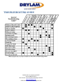
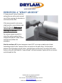
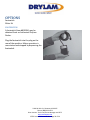
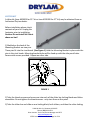
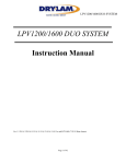
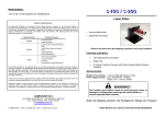
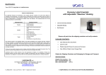
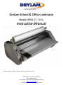
DryLam School & Office Laminator
Model 27STA (27"120V)
Instruction Manual
Revised 1/20/14, 1/28/14, 2/18/14, 3/4/14, 3/13/15 Brian Jennett
23220 W. 84th St., Shawnee, KS 66227
Phone: (888) 633-1973
Brian Jennett- Tech-Line/Service Manager ext 8575
http://www.DryLam.com
27STA Instruction manual.docx Page 1 of 24
Contents
27STA SPECIFICATIONS ........................................................................................................................................................... 3
IMPORTANT INFORMATION ................................................................................................................................................... 3
INTRODUCTION ....................................................................................................................................................................... 7
UNPACKING AND SETUP ......................................................................................................................................................... 9
INFORMATION ABOUT LAMINATING FILM ............................................................................................................................. 9
OPERATING ............................................................................................................................................................................. 9
Control Panel....................................................................................................................................................................... 9
ADDITIONAL FEATURES ......................................................................................................................................................... 11
Key switch ......................................................................................................................................................................... 11
Hand Held Cutter .............................................................................................................................................................. 11
LOADING FILM ...................................................................................................................................................................... 12
THREADING PROCEDURE ...................................................................................................................................................... 13
TENSION ADJUSTMENT ......................................................................................................................................................... 16
MAINTAINING THE DRYLAM LAMINATOR ............................................................................................................................ 17
TROUBLESHOOTING GUIDE .................................................................................................................................................. 18
REMOVING A “WRAP-AROUND”........................................................................................................................................... 19
OPTIONS ................................................................................................................................................................................ 20
FOOTSWITCH .................................................................................................................................................................... 20
SLITTER KIT ........................................................................................................................................................................ 21
WIRING DIAGRAM................................................................................................................................................................. 23
EQUIPMENT WARRANTY....................................................................................................................................................... 24
23220 W. 84th St., Shawnee, KS 66227
Phone: (888) 633-1973
Brian Jennett- Tech-Line/Service Manager ext 8575
http://www.DryLam.com
27STA Instruction manual.docx Page 2 of 24
27STA SPECIFICATIONS
Item
Feed Table Width
Height
Width (overall)
Depth (with feed tray installed)
Net weight
Shipping weight
Width of Lamination
Electrical
27STA (120V)
27"
15”
34”
20"
66 lbs.
88 lbs.
27"
120VAC 60 Hz 1400W
IMPORTANT INFORMATION
• Read all the safety and operating instructions before connecting or using this unit.
• Retain this notice and the owner’s manual for future reference.
• Adhere to all warnings and operating instructions.
• Do not use this unit near water (e.g. near a bathtub, etc.)
• The wearing of ties or jewelry while operating a laminator may be hazardous to the
operator.
• Warning: Do not touch Hot Surfaces such as heat shoes and heat rollers.
• Do not install optional slitter kit if Heat shoes are hot.
• This unit should be installed so that its location or position does not interfere with its proper
ventilation. For example, it should not be situated on a bed, sofa, rug or similar surface that
may block the ventilation openings; or placed in a built-in installation, such as bookcase or
cabinet or against the wall, that may impede the flow of air through its ventilation openings.
• This unit should be situated away from heat sources such as radiators, heat registers, stoves,
etc.
23220 W. 84th St., Shawnee, KS 66227
Phone: (888) 633-1973
Brian Jennett- Tech-Line/Service Manager ext 8575
http://www.DryLam.com
27STA Instruction manual.docx Page 3 of 24
• This unit should only be connected to a power supply outlet of the voltage, amperage and
Frequency marked on its serial tag.
• For 120 volt machines the socket outlet shall be installed near the equipment and be easily
accessible.
•For 240 volt machines a readily accessible disconnect device shall be incorporated in the
building installation wiring.
• The power supply cord should be routed so that it is not likely to be walked upon or pinched,
especially near the plug, convenience receptacles, or where the cord exits from the unit.
• Unplug the machine during any machine repairs.
• Clean unit only as recommended in this instruction manual.
• Make sure to remove the Feed Table before reversing the machine!
• Care should be taken so that objects do not fall, and liquids are not spilled, into the
enclosure through any openings.
• Caution: The Cutter blade is extremely sharp. Please handle carefully and dispose of
properly.
Save Your Carton! DryLam ships laminators in a special carton which protect them from
damage. Please store your carton in case your laminator should ever require servicing.
Remove the laminator from its box by grasping the housings and pulling up. Do not use rollers
or shafts as handles- this could cause damage.
The power supply cord should be unplugged from the wall outlet when it is to be unused for a
long period of time.
This manual is provided as an Operator’s Manual and covers most situations you will
encounter while using your laminator. It is not a Technical Service manual. For technical
assistance beyond what this manual provides, contact the DryLam Tech-Line at the email
23220 W. 84th St., Shawnee, KS 66227
Phone: (888) 633-1973
Brian Jennett- Tech-Line/Service Manager ext 8575
http://www.DryLam.com
27STA Instruction manual.docx Page 4 of 24
address and phone number below.
DryLam is a product line of
DryLam, LLC
23220 West 84th Street
Shawnee, KS 66227
www.drylam.com
[email protected]
Phone (888) 633-1973 Tech-Line/Service- Ext 8575
23220 W. 84th St., Shawnee, KS 66227
Phone: (888) 633-1973
Brian Jennett- Tech-Line/Service Manager ext 8575
http://www.DryLam.com
27STA Instruction manual.docx Page 5 of 24
Notes
RECORD SERIAL NUMBER HERE (LOCATED ON REAR PANEL OF MACHINE):
23220 W. 84th St., Shawnee, KS 66227
Phone: (888) 633-1973
Brian Jennett- Tech-Line/Service Manager ext 8575
http://www.DryLam.com
27STA Instruction manual.docx Page 6 of 24
INTRODUCTION
The DryLam 27STA Laminator, with variable speed and reverse is a reliable, easy-to-use
professional laminator designed to laminate a variety of materials using 25"or 27" laminating
film. The 27STA is capable of lamination from 1 to 9 feet per minute and can be reversed by
the push of a button.
Tension Adjusting Knobs (A)
are conveniently located on
the Supply Mandrels (B) on
the right side panel for easy
access. A Control Panel (C) is
located on the Left Housing
(D), and is equipped with a
Power Button (E) to turn the
machine on, Temperature Up
(F) and Temperature Down (G)
buttons, two Preset buttons
(H), a Motor Start button (I) to
start the motor turning, Speed
Up (J) and Speed Down (K)
buttons to adjust the speed
as necessary, a Motor
Stop/Reverse button (L), a
User Preset button (M) to
save your own settings, and
a Count Reset button (N)
which resets the usage
counter. The Display button
(O) toggles the Display (P)
between 3 settings. The
Feed Tray (Q) and Feed
Guide (R) provide a smooth,
durable paper path and the
Heat Guard (S) protects
23220 W. 84th St., Shawnee, KS 66227
Phone: (888) 633-1973
Brian Jennett- Tech-Line/Service Manager ext 8575
http://www.DryLam.com
27STA Instruction manual.docx Page 7 of 24
hands from hot surfaces inside.
Teflon coated Heat Shoes (T)
minimize friction. The Cutter (U)
cuts and trims your laminated
documents and the Key switch
(V) prevents unauthorized usage
by preventing the motor from
running.
23220 W. 84th St., Shawnee, KS 66227
Phone: (888) 633-1973
Brian Jennett- Tech-Line/Service Manager ext 8575
http://www.DryLam.com
27STA Instruction manual.docx Page 8 of 24
UNPACKING AND SETUP
Remove the laminator from its box by grasping the housings and pulling up. Do not use rollers
or shafts as handles- this could cause damage. Choose a location for the laminator that is
clean, well-lighted and draft free. Make sure it is not in the path of any fans, room air
conditioners, or positioned too close to the wall. The laminator comes fully assembled. All you
have to do is load the film onto the supply mandrels, thread the film through the machine, and
install the feed table.
INFORMATION ABOUT LAMINATING FILM
Laminating film is made up of two layers: a glossy layer which gives the lamination its strength,
clarity and rigidity, and a dull or matte side which is heat activated and serves as the “glue” to
bond the film to the product being laminated. Once heated, small amounts of the “glue” side
can stick to the heat shoes and rollers and must be periodically cleaned from the laminator.
Laminating film is available in a variety of different lengths, qualities, widths and thicknesses.
The DryLam 27STA Laminator is designed to use 1.5 mil (#150), and 3 mil (#300), thick films.
OPERATING
Control Panel
The control panel is located on the left side of the laminator. This panel is used to control the
various machine functions listed below.
Display (O,P)
The display will show the 3 different parameters of the machine- temperature, speed, and
usage counter. The default display mode is usage counter. If the machine is not yet up to
temperature, the machine will display the set point temperature. When the machine reaches
the set point temperature, the usage counter will be displayed and the “READY” LED will light.
If the speed is adjusted, the machine will momentarily display the speed and then quickly
return to usage counter mode. The "Display" button allows you to toggle between any of the 3
settings for the display.
Power (E)
The "On/Off" button turns the machine on.
Heat (F,G)
23220 W. 84th St., Shawnee, KS 66227
Phone: (888) 633-1973
Brian Jennett- Tech-Line/Service Manager ext 8575
http://www.DryLam.com
27STA Instruction manual.docx Page 9 of 24
The temperature controls are the "Temp Up" and "Temp Down" buttons (yellow blocks). These
buttons are used to adjust the temperature currently displayed. The temperature displayed is
the temperature set point. This is the temperature that the machine will reach and hold. The
temperature can be increased or decreased in 1° increments by pressing and releasing the up
or down button. To rapidly increase or decrease the temperature, press and hold the button.
When the machine reaches the set point temperature, the Ready light (green) will illuminate,
and a two second beep will sound. If a significant change in the set point temperature occurs,
the Wait light (red) illuminates until the laminator reaches the new set point temperature. At
this time the Ready light will illuminate again. Note: depending on room conditions and
desired set point, it will take between 20 and 30 minutes for the ready indicator to come on.
Standard Presets (H)
The Laminator is equipped with 2 factory presets. The buttons are labeled 275 and 225. These
buttons will set both a speed and temperature that being (275°F and 3 Feet per minute) and
(225°F and 3 feet per minute). If one of the presets is engaged, its corresponding LED will be
illuminated.
Motor (I,J,K,L)
The motor controls are the 4 buttons on the right side of the control panel. The "Start" button
will start the motor which will run at the current speed setting. The "Speed Up" and "Speed
Down" buttons will adjust the speed setting. Pressing and releasing the button once will
increment the speed by 0.1 ft/min (0.1 meters/min). To rapidly increase or decrease the
speed, press and hold the corresponding button. To stop the motor, press and release the
"Stop/Reverse" button. To reverse the machine, press and hold the "Stop/Reverse" button.
The motor will remain in reverse as long as the button is depressed.
User Preset (M)
The Laminator is equipped with a user defined "Preset" button. This button can be used to
save a speed and temperature setting that you have defined. With the machine's speed and
temperature set to your preferred settings, press and hold the "Preset" button until the
beeper sounds and the preset light comes on. To recall this setting at a later time, press and
release the "Preset" button.
Usage Counter (N)
The Laminator is equipped with a usage counter that will indicate the feet (meters) of film
used. This counter will appear on the display whenever the feet indicator light is on. This
23220 W. 84th St., Shawnee, KS 66227
Phone: (888) 633-1973
Brian Jennett- Tech-Line/Service Manager ext 8575
http://www.DryLam.com
27STA Instruction manual.docx Page 10 of 24
counter can be reset to zero by pressing the "Count Reset" button once the display is showing
the usage counter.
ADDITIONAL FEATURES
Key switch
The key switch (located just below the control panel) locks out the motor, allowing the
machine to remain heated; yet, preventing unauthorized usage when in the locked position.
Hand Held Cutter
If additional cutters or cutter blades are
needed, they may be obtained from
DryLam.
The hand held cutter blade can be
replaced by removing the small screw
on the back of the cutter, then
removing the cutter back. Caution: The
cutter blade is extremely sharp. Please
handle carefully and dispose of
properly. Remove and discard the old
blade. Re-install cutter back and screw.
Caution: Do not over tighten screw.
23220 W. 84th St., Shawnee, KS 66227
Phone: (888) 633-1973
Brian Jennett- Tech-Line/Service Manager ext 8575
http://www.DryLam.com
27STA Instruction manual.docx Page 11 of 24
LOADING FILM
Unpack the upper and lower supply mandrels. The upper and lower mandrels are different.
The word “TOP” is stamped on the shaft of the upper mandrel and the word “LOW” is
stamped on the shaft of the lower mandrel. The ends of each mandrel are also different. The
“hanger” end fits in the bracket on the left side of the laminator. The “slot end” fits into the
tensioner on the right side.
Slide the film roll onto the mandrel by
rotating the mandrel in the opposite
direction of the gripper points, leaving
equal lengths of mandrel sticking out
of each end. The film roll will slide over
the gripper, which will keep the roll
from turning on the shaft.
Load the mandrel on the laminator by
inserting the slot end of the mandrel
into the tensioner on the right side
and then lowering the hanger end into
the bracket on the left side.
23220 W. 84th St., Shawnee, KS 66227
Phone: (888) 633-1973
Brian Jennett- Tech-Line/Service Manager ext 8575
http://www.DryLam.com
27STA Instruction manual.docx Page 12 of 24
THREADING PROCEDURE
Your laminator was tested at the factory. The film that was used for testing may still be in the
laminator. If so, remove the test film by
removing the feed tray and the heat guard and
reversing the film back out the front of the
laminator. To do so, hold the STOP/REVERSE
button down. The motor will reverse and the
film piece will exit the front.
23220 W. 84th St., Shawnee, KS 66227
Phone: (888) 633-1973
Brian Jennett- Tech-Line/Service Manager ext 8575
http://www.DryLam.com
27STA Instruction manual.docx Page 13 of 24
THREADING PROCEDURE (cont’d)
Remove the feed tray and the heat guard.
Thread the film as shown in the figure on
the right. Pull the film around the idler
rollers as shown. Do not mistake the
reinforcing bar for the idler roller. Make
sure the glossy and dull sides of the film are
as indicated in the diagram. Position the
threading board provided.
Turn power on by pressing the ON/OFF
button. Turn the key switch to on (the
horizontal position).
Start the motor by pressing the "Start"
button, and reduce the speed to 1
foot/min. Push the threading board and
film in between the heat shoes. The
internal rollers will pull the film through
the heat shoes until it comes out between
the rollers at the back of the laminator.
NOTE: Keep fingers away from the rollers
at the rear of the laminator!
Check the film overlap. Slide the top and
bottom film rolls from side to side on
the mandrels so that the film is
perfectly aligned (overlapped) top and
bottom (Note: poor overlap will cause
the film to deposit residue on the heat
shoes and rollers, so this procedure is
critical). Replace feed tray and heat
guard.
23220 W. 84th St., Shawnee, KS 66227
Phone: (888) 633-1973
Brian Jennett- Tech-Line/Service Manager ext 8575
http://www.DryLam.com
27STA Instruction manual.docx Page 14 of 24
LAMINATING
Only after the machine is loaded with film (see “Loading Film: 1" Mandrel”) and properly
threaded (see “Threading the Film), is
it ready to laminate. If the machine
has not been threaded properly
damage to the machine or operator
may occur. Ensure that the laminator
has reached the preset temperature.
This will be indicated by the ready
light being illuminated. Place
document on the feed table and align
with the feed guide to assure straight
and even lamination. Start the motor
with the "Start" button and adjust the
speed as necessary.
If necessary, adjust the supply roll tension (see E. Supply Roll Tension Adjustment). With both
hands, guide the document into the throat of the laminator. While the document is pulled into
the laminating rollers, keep
document flat on the feed table
while applying a slight back pressure.
As the document exits the rear
rollers, allow 3" to 6" of film to clear
the rollers at the end of your
document and turn the motor switch
to stop. Using the hand held cutter,
hold tension on the laminated
document and slice through the film
to release the document. Multiple
documents can be run successively if
desired and cut at a later time.
23220 W. 84th St., Shawnee, KS 66227
Phone: (888) 633-1973
Brian Jennett- Tech-Line/Service Manager ext 8575
http://www.DryLam.com
27STA Instruction manual.docx Page 15 of 24
TENSION ADJUSTMENT
Top and bottom supply rolls should always have about the same tension. By turning the top
roll with one hand, and the bottom roll with the other hand, it can be determined if one of the
rolls is tighter than the other.
Note: Too much tension can destroy film, documents, and damage the machine.
Always adjust the tension to the minimum
amount required. Do this by loosening the
tension knobs until there is no tension on the
film. With the machine threaded and at
operating temperature, turn the motor
switch to forward and adjust the speed to
the desired operating speed. Tighten the
adjusting knobs only until the wrinkles in the
film (as they cross the heat shoes) are
removed.
Note: As the diameter of the film roll
decreases, tension should be reduced.
To increase tension, turn the adjusting knob clockwise. To decrease tension, turn the knob
counterclockwise. If the tension is not equal top and bottom, the laminated product will curl. If
the material curls up as it comes out of the machine, the top roll is probably tighter than the
bottom. If it curls down, the bottom roll is probably tighter.
Note: Make sure the black disks are flat against the side panel. They should be rotating, both
top and bottom, while film is feeding.
23220 W. 84th St., Shawnee, KS 66227
Phone: (888) 633-1973
Brian Jennett- Tech-Line/Service Manager ext 8575
http://www.DryLam.com
27STA Instruction manual.docx Page 16 of 24
MAINTAINING THE DRYLAM LAMINATOR
Care and Cleaning
In the normal course of operating the DryLam Laminator, dirt and adhesive will accumulate on
the heat shoes and rubber rollers (Laminating produces static electricity which attracts
airborne dust and dirt). Regular inspection and cleaning will assure that this does not become
a problem.
Never use hard, sharp, or abrasive items to
clean the heat shoes. The shoes are coated
with a non-stick surface that could easily be
damaged. Likewise, do not use sharp metallic
objects or steel wool to clean the rubber
rollers. Any scratches, indentations, or marks
left on the rollers will appear on the
laminated product.
To clean the shoes and rollers, use DryLam’s
Cleaning Kit (product code CLKIT). If a
cleaning kit is not readily available, rubbing
(Isopropyl) alcohol and a quality cloth will do an adequate job.
It is highly recommended to use DryLam’s Maintenance Kit (product code 01300) after
cleaning.
23220 W. 84th St., Shawnee, KS 66227
Phone: (888) 633-1973
Brian Jennett- Tech-Line/Service Manager ext 8575
http://www.DryLam.com
27STA Instruction manual.docx Page 17 of 24
TROUBLESHOOTING GUIDE
23220 W. 84th St., Shawnee, KS 66227
Phone: (888) 633-1973
Brian Jennett- Tech-Line/Service Manager ext 8575
http://www.DryLam.com
27STA Instruction manual.docx Page 18 of 24
REMOVING A “WRAP-AROUND”
A "wrap-around" occurs if the film
exiting the rear rollers curls around
one of them causing the laminate to
wind around the roller.
If the wrap-around is not severe,
simply use the reverse feature and
back the film out. Make sure to
remove the Feed Table before
reversing the machine!
For extreme wrap-arounds (i.e.
when film and/or product have
wrapped around the rubber rollers
several times) follow this
procedure:
Shut the machine off! DryLam Laminators have 3/32” set screws at both ends of each
laminating and pull roller. Loosen all four set screws on the pull rollers. Cut the plastic
between the laminating and pull rollers, grab the loose end and pull. The rollers will rotate
freely on the roll shafts and the “wrap- around” will easily unwrap. Tighten all the set screws
and rethread the film.
23220 W. 84th St., Shawnee, KS 66227
Phone: (888) 633-1973
Brian Jennett- Tech-Line/Service Manager ext 8575
http://www.DryLam.com
27STA Instruction manual.docx Page 19 of 24
OPTIONS
Footswitch
Slitter Kit
FOOTSWITCH
A footswitch (item #802054) may be
obtained from an Authorized DryLam
Dealer.
Plug the footswitch into the plug on the
rear of the machine. Motor operation is
now started and stopped by depressing the
footswitch.
23220 W. 84th St., Shawnee, KS 66227
Phone: (888) 633-1973
Brian Jennett- Tech-Line/Service Manager ext 8575
http://www.DryLam.com
27STA Instruction manual.docx Page 20 of 24
SLITTER KIT
A slitter kit (item #202005 for 25" kit or item # 202000 for 27" kit) may be obtained from an
Authorized DryLam dealer.
Before installation please check
contents of your kit. Unplug the
laminator prior to installation.
Caution: Do not install kit if Heat
shoes are hot!
1) Molded on the back of the
Mounting Bracket are two pins.
These pins fit into the rivet heads. (See Figure 1) Hold the Mounting Bracket in place with the
pins in the rivet heads. Mounting bracket holes will be lined up with the side panel holes.
Secure with screws provided. Repeat on other side.
FIGURE 1
2) Take the thumb screws and screw one into each of the slitter bar locking blocks and slitter
assemblies. Do not tighten the thumb screws - only start them at this point.
3) Take the slitter bar and slide on one locking block, both slitters, and then the other locking
23220 W. 84th St., Shawnee, KS 66227
Phone: (888) 633-1973
Brian Jennett- Tech-Line/Service Manager ext 8575
http://www.DryLam.com
27STA Instruction manual.docx Page 21 of 24
block. Be sure the thumb screws are all on top, and both slitter edges are facing the front of
the laminator. (See Figure 2) Adjust slitters to cut where you wish and tighten the thumb
screws. Remove protective coating from slitter blades.
FIGURE 2
4) Drop slitter into the mounting brackets and press slitters through laminating film. Once
slitter bar is in place, slide each locking block out until it contacts the mounting brackets,
tighten the thumb screws.
NOTE: When pressing the slitters through the laminating film, try cutting a slot in the film with
a utility knife first.
23220 W. 84th St., Shawnee, KS 66227
Phone: (888) 633-1973
Brian Jennett- Tech-Line/Service Manager ext 8575
http://www.DryLam.com
27STA Instruction manual.docx Page 22 of 24
WIRING DIAGRAM
23220 W. 84th St., Shawnee, KS 66227
Phone: (888) 633-1973
Brian Jennett- Tech-Line/Service Manager ext 8575
http://www.DryLam.com
27STA Instruction manual.docx Page 23 of 24
EQUIPMENT WARRANTY
We warrant to the original purchaser the equipment manufactured by us to be free from
defects in material and workmanship under normal use and service. Our obligation under this
warranty shall be limited to the repair of any part or parts which may thus prove defective
under normal use and service within one year from the date of shipment and which our
examination shall disclose to our satisfaction to be thus defective. When necessary, purchaser
shall properly pack (in the original carton/packing material or with that assigned by DryLam)
and return the unit to the nearest DryLam Service Center, freight and insurance prepaid.
THIS WARRANTY IS EXPRESSLY IN LIEU OF ALL OTHER WARRANTIES EXPRESSED OR IMPLIED
INCLUDING THE WARRANTIES OF THE MERCHANTABILITY AND FITNESS FOR USE AND OF ALL
OTHER OBLIGATIONS OR LIABILITIES ON OUR PART, AND WE NEITHER ASSUME NOR
AUTHORIZE ANY OTHER PERSON TO ASSUME FOR US, ANY OTHER LIABILITY IN CONNECTION
WITH THE SALE OF THIS MACHINE OR ANY PART THEREOF WHICH HAS BEEN SUBJECT TO
ACCIDENT, NEGLIGENCE, ALTERATION, ABUSE OR MISUSE. WE MAKE NO WARRANTY
WHATSOEVER IN RESPECT TO ACCESSORIES OR PARTS NOT SUPPLIED BY US. THE TERM
"ORIGINAL PURCHASER" AS USED IN THIS WARRANTY, SHALL BE DEEMED TO MEAN THE
PERSON OR COMPANY WHO FIRST PUTS THE DRYLAM EQUIPMENT INTO SERVICE. THIS
WARRANTY SHALL APPLY ONLY WITHIN THE BOUNDARIES OF THE CONTINENTAL UNITED
STATES.
DryLam LLC
Shawnee, KS
DryLam 652755 · Rev. 3b
11120/08
23220 W. 84th St., Shawnee, KS 66227
Phone: (888) 633-1973
Brian Jennett- Tech-Line/Service Manager ext 8575
http://www.DryLam.com
27STA Instruction manual.docx Page 24 of 24