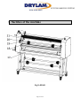
1
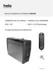
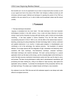
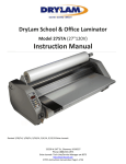
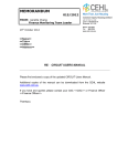
LPV1200/1600 DUO SYSTEM
LPV1200/1600 DUO SYSTEM
Instruction Manual
Ver. 1 1/28/14, 2/28/14, 8/13/14, 11/5/14, 12/4/14, 5/14/15 to add LPV1600, 7/29/15 Brian Jennett
Page 1 of 42
LPV1200/1600 DUO SYSTEM
Contents
1. Specifications .............................................................................................................3
2. Applications & Characteristics of the LPV1200/1600 DUO SYSTEM....................5
3. Requirements for Use ................................................................................................6
4. Safety Requirements ..................................................................................................7
5. Sketches of the machine ............................................................................................9
6. Control Panel ...........................................................................................................12
7. Removal & Installation of Laminator ......................................................................14
8. Preparations Before Starting Up ..............................................................................23
9. Adjustment of Roller Pressure .................................................................................26
10. Film Tension Adjustment .......................................................................................27
11. Operation Instructions ............................................................................................28
12. Common Solutions To Quality Issues ...................................................................37
14. Maintenance & Repairs .........................................................................................41
15. Service....................................................................................................................42
Page 2 of 42
LPV1200/1600 DUO SYSTEM
1. Specifications
LPV1600 DUO
Maximum Laminating Width
LPV1200 DUO
47.2”
Maximum Lift of the rollers
Maximum rated input power
Amperage
1.2”
4250W
17.7A
1”
6000W
25A
Carton Dimensions (WxLxH)
75” x 39” x 35”
94” x 39” x 35”
Assembled Laminator Dimensions (WxLxH)
67” x 34” x 50”
85” x 34” x 50”
529 lbs.
704 lbs.
Type
Net Weight
65”
0.3 ~ 12.5 ft/min
Speed Adjustment Range
86°F ~ 266°F
Temperature Adjustment Range
Rated operating voltage and frequency
AC240V 60Hz
NEMA #6-30 (requires 6-30R
receptacle)
50°F to 105°F
Plug
Ambient operating temperature range
Storage and Transportation Temperature
Ambient operating humidity
-68°F - 140°F
40%—70% Perfect humidity: 55%.
Minimum operating space
10’ x 10’
Warning: Please pay attention to the rated voltages of this machine. Do not
misuse the source voltages.
Please read and understand this manual and the machine’s limitations before
operating!
NOTES:
Record serial number here:
Page 3 of 42
LPV1200/1600 DUO SYSTEM
Dear User,
Thank you for choosing the LPV1200/1600 DUO SYSTEM. This
laminator can give you great performance and long lasting reliability. It
can help you enjoy its various perfect laminating features and achieve
good-quality re-making texts and drawings with simple operations. It can
also bring you a comfortable and high-quality new laminating standard
with satisfying results.
Attention:
To ensure safety to the operator and avoid damage to electric
equipment, be sure to check the reliability of the earth protective
conductor of the power receptacle before operating the machine.
Please retain this operation manual for future reference.
Please pay special attention to paragraphs with warning symbols, which are vital to
the proper use and maintenance of the machine and to the safety of users.
Please comply with the operational warnings in this manual.
Page 4 of 42
LPV1200/1600 DUO SYSTEM
2. Applications & Characteristics of the
LPV1200/1600 DUO SYSTEM
The LPV1200/1600 DUO SYSTEM laminator was designed for lamination of large
scale computer text, drawings and prints. The DUO will perform cold and/or hot
laminating and plastic packaging. “1200” or “1600” refers to the maximum width (in
mm) that this machine is capable of laminating.
This laminator is more applicable for materials of adhesive films and application
requirements during the laminating operation, so that cold and hot adhesive films
could be used for the cold laminating and plastic packaging of large pictures, winding
films for continual mounting of text and drawings while used for continual single and
double surface laminating for text and drawings under high-temperature during the
laminating operations.
This laminator is suited to various industries, particularly printing, color sprayed
drawings, advertisement, manufacturing, etc.
Proper design, simple solid structure, adjustable temperature/speed and nimble
maneuverability make the LPV1200/1600 DUO SYSTEM the perfect machine for
quick and effective mounting, laminating and plastic packaging.
Page 5 of 42
LPV1200/1600 DUO SYSTEM
3. Requirements for Use
This machine should be used in ambient temperatures of 50°F to 105°F. Avoid higher
temperatures and high humidity levels (see specifications, page 3).
Due to static adherence of adhesive films, the production environment should be kept
as clean as possible.
This machine should only be operated on its own stand.
Operating space: enough space should be kept so as to ensure safe and effective
application. The recommended minimum operating space for the machine is 10’ x
10’.
Do not place this machine in direct sunlight.
Do not leave pictures and articles on, or between the rubber-covered rollers for long
periods of time after laminating.
If the machine is to be unused for a long period of time it is recommended to remove
the adhesive film, pictures and articles. Avoid long-term adherence of the adhesive
film to the surface of the rubber-covered roller.
To prevent color change of cold mounting film it is recommended that laminated
prints not be affixed to rubber materials.
It can laminate continuously an object less than 0.47” thick. And for an object over
1/2” but below 1”, the work can be done by using the pedal switch.
Page 6 of 42
LPV1200/1600 DUO SYSTEM
4. Safety Requirements
The power supply wires should be connected with air switches with leakage
protection and the rated current should be 20A or more.
The outlet should be near the machine for convenient use. Do not use extension
cords.
All building wiring and other electrical components should comply with the power
requirements of this machine.
This machine must be grounded to ensure safe use during operation.
No one, except the trained operator of this machine, is allowed to touch any
components or control buttons.
Don’t use damaged wiring and outlets with electric leakage. Wires and cords should
not be squeezed or crushed by any hard objects.
If abnormal circumstances occur, shut off the power supply.
This machine is equipped with a heating system. Do not touch the surface of
rollers during operations so as to avoid burns.
When laminating, start by operating at low speed and by using the pedal switch.
Keep rigid materials away from the surfaces of the rollers during operations,
otherwise the rollers could be damaged which will adversely affect lamination
quality.
During operation, ensure that clothing and hair do not come in contact with
the machine.
During laminating operation don’t place anything except materials to be laminated on
Page 7 of 42
LPV1200/1600 DUO SYSTEM
the machine. Any accidental entanglements will cause damage to rollers or other parts
the machine or the operator.
Do not attempt to laminate metal materials or other hard objects. Do not put
sharp objects into the machine (for example, tools, rulers and knives, etc.).
To avoid damage to rollers do not cut adhesive films directly on the surfaces of the
rollers.
To avoid foot injuries be cautious of the casters.
When service is required no one except professionals shall open the machine for
repairs.
Before repairing any mechanical or electrical problems, first shut off the
power supply. Never adjust or service the machine with the power on. Shut off this
machine after laminating is finished.
Unplug the machine if it is not being used for long periods of time and lift the
upper roller to avoid any distortion of roller’s surface.
Do not use corrosive liquids to clean this machine, otherwise the machine or rollers
could be damaged. Use only alcohol and a soft dry cloth to wipe the surfaces of the
rollers.
Page 8 of 42
LPV1200/1600 DUO SYSTEM
5. Sketches of the machine
Fig 1a FRONT
Page 9 of 42
LPV1200/1600 DUO SYSTEM
5. Sketches of the machine
Fig 1b REAR
Page 10 of 42
LPV1200/1600 DUO SYSTEM
5. Sketches of the machine
1
Left cabinet
2
Emergency stop switch
3
Linkage shaft for pressure adjustment
4
Backing paper mandrel
5
Front guard shield
6
Right cabinet
7
Pressure adjust hand wheel of front roller
8
Control panel
9
Pressure adjust hand wheel of rear roller
10
Stand
11
Mandrel shaft
12
Sleeve of mandrel
13
Front working panel
14
The lower support plate of feeding roller
15
Castor
16
Positioning plate of front working panel
17
Support beam
18
Rear working panel
19
Brackets of upper mandrel
20
Rear upper roller
21
Front upper roller
See the Exploded Views/Parts List for more detail and replacement parts.
Page 11 of 42
LPV1200/1600 DUO SYSTEM
6. Control Panel
Fig.2
1
Power Indicator
2
Upper Roller Heat Indicator
3
Lower Roller Heat Indicator
4
Temperature adjustment for Upper Roller
5
Temperature adjustment for Lower Roller
6
Motor Direction Switch
7
Speed Control Adjustment
8
Continue/Step Switch
9
Temperature Display For Lower Roller
10
Temperature Display for Upper Roller
Page 12 of 42
LPV1200/1600 DUO SYSTEM
6. Control Panel (cont’d)
● The control board and display are located on the right side of the machine. These
functions include motor speed regulating, forward/reverse rotation, upper roller
heating, lower roller heating and continue/step conversion setting.
● The roller temperature controls have switches. When turned counterclockwise
the roller stops heating; when turned clockwise the rollers will heat.
● The two digital display screens show the temperature of the rollers.
● When the machine is connected to power and switched on the power indicator
lights up.
● Upper roller heating indicator and lower roller heating indicator are “Red” during
heating and “Green” when fully heated.
● The speeds of roller rotation can be adjusted with the speed control.
● Roller direction can be exchanged by pressing the Forward / Reverse button.
● The pedal switch can be used with the switch in “STEP” mode.
● Precautions during operations:
EARLY MODELS (S/N beginning with 1308, and lower): When the machine is
stopped by an optical sensor there is a 5 second waiting period for the motor to start
again. Please turn to “STEP” first after 5 seconds and then turn to “Continuous” again
to restore motor operation.
LATER MODELS (S/N beginning with 1408, and higher): These models are not
equipped with an optical sensor. Raising the heat guard stops the motor and shuts off
all power to the laminator.
Page 13 of 42
LPV1200/1600 DUO SYSTEM
7. Removal & Installation of Laminator
I. Removal of the Machine from the Crate
Please refer to figure 3)
1
2
Fig. 3
Upper cover of crate
Stand legs and casters
Remove screws securing the top of the crate and remove the stand legs/casters.
Ⅱ Assembling the Stand
Please refer to figure 4)
Take the frame out of packaging box and make installations following the figure 4.
Connect and fix the supporting board of frame to the beams of the frame with inner
hexangular screws hard and unfailingly
Page 14 of 42
LPV1200/1600 DUO SYSTEM
7. Removal & Installation of Laminator (cont’d)
Fig. 4
1
Tightening screw
2
Stand legs/casters
3
Upper support beam
4
Lower support beam
Place the installed stand aside (on a level ground) for future use.
Page 15 of 42
LPV1200/1600 DUO SYSTEM
7. Removal & Installation of Laminator (cont’d)
Ⅲ Removal of this machine
(Please refer to figure 5)
Fig. 5
1
Rack support beam
2
Laminator
3
Feeding roller (module)
4
Feeding roller holder
5
Wood belt fixing the laminator
6
Pallet of the packing box
The laminator is sealed with a plastic bag to keep out dust and moisture.
Page 16 of 42
LPV1200/1600 DUO SYSTEM
7. Removal & Installation of Laminator (cont’d)
1. The laminator is lifted up to separate from the packing case base.
Ⅳ Installations of the machine on its stand
(Please refer to figure 6)
Lift up the laminator and install on the stand (Please refer to figure 6)
After the laminator is installed on the stand, open end covers on both sides of the
laminator and use socket head cap screws and leveling bending-plate in the accessory
case to connect the laminator with the stand. Consider installing the heaters. Then,
close the end covers on both sides of the laminator to complete the connection.
Fig. 6
Page 17 of 42
LPV1200/1600 DUO SYSTEM
7. Removal & Installation of Laminator (cont’d)
1
Main machine
2
Leveling bending plate
3
Stand
▲ Take Care not to hurt your finger or body while moving the machine and its stand.
▲ Be careful not to injure your foot by the castor wheels.
Ⅴ Installing Heat Tubes
Warning: Do not attempt this with the power on!
5A Insert Heat tubes
1. Remove gap Hand wheel from right side cover
2. Remove the right and left cabinet covers.
3. Remove left and right heater support brackets
4. Insert heat tube through the core of the roller, aligning Ends with the flat spot in the
supports
Page 18 of 42
LPV1200/1600 DUO SYSTEM
7. Removal & Installation of Laminator (cont’d)
5. Replace left and right heater support brackets
Fig. 7
1
2
3
4
5
Screw
Rubber cushion
Heat tube
Support Bracket
Roller
Page 19 of 42
LPV1200/1600 DUO SYSTEM
7. Removal & Installation of Laminator (cont’d)
4
2
5B Connect electric wires
1. With the tube in place, remove the porcelain inserter, porcelain tube, hex nut and
flat washer from both ends
2. Connect the two ends to the electric wire connectors.
3. Replace flat washer, hex nut, porcelain tube and porcelain inserter
Page 20 of 42
LPV1200/1600 DUO SYSTEM
7. Removal & Installation of Laminator (cont’d)
4. Replace side covers and gap wheel
1
2
3
4
5
Porcelain insert
Porcelain cap
Hex nut
Flat washer
Electric wire connector
2
1
6
15
5
1
6
5
6
5
Ⅵ Installations of Upper Mandrel Assembly and Bracket
Please refer to figure 7)
Page 21 of 42
LPV1200/1600 DUO SYSTEM
(Figure 7)
1 Mandrel (components)
2 Fixing bolts
3 Connecting plate of the mandrel
Fix the two connecting plates on the machine with the bolts.
Put the mandrel (components) into the grooves of the brackets.
Page 22 of 42
LPV1200/1600 DUO SYSTEM
8. Preparations Before Starting Up
Connecting the power supply, turn on the machine, and you can choose function
switches according to practical needs.
Press Cold for cold laminating work.
Press Hot for hot laminating work.
Press either Single, or Double for single roller heat-up or double roller heat-up.
Selection of adhesive films: it is essentials to select good quality film, which can help
get an ideal laminated product.
The adhesive films should be a little narrower than the text and drawings (When there
is some blank on the edges around); if there is no blank frames available for cutting,
lining papers should be mounted on the back of text and drawings (or on both sides of
the text and drawings) and the lining paper should be wider than the adhesive films.
Installing adhesive Films Rolls on the mandrel:
Loosen the fastening screws on the orientation covers of mandrel and take down the
axis caps on one end and the orientation covers of mandrel;
Put the film rolls on the core of the mandrel;
Put the removed orientation covers through one end of paper core and then fit on the
axis caps of mandrel.
Adjust the distances between the orientation covers of the two positioning sleeves so
as to place the film roll in the central part.
Fasten the screws of supporting covers of mandrel (Note: there should be 3 to 5mm
clearance between the orientation cover of mandrel and adjust the cover of mandrel
for transverse adjustment);
Adjust the fabrication forces by turning the adjustment covers of the mandrel.
(Be careful: the friction forces should not be too great) (please refer to figure 8)
Page 23 of 42
LPV1200/1600 DUO SYSTEM
1
Shaft of the mandrel
2
Cold film with lining paper
3
Paper tube
4
Positioning sleeves
5
Adjust nuts
6
Fastening screws of positioning collar
7
Positioning collar
Installations and Adjustment Methods for backing Paper Roller (please refer to Figure
9)
1. Make anticlockwise turns of pressure adjustment nuts on the right, to take the
backing paper roll down. A clockwise turn helps to load the roll on.
2. The paper tube for collecting backing paper may be loaded on the backing paper
roller, or stick the backing paper onto the backing paper roller directly after being
separated with the film.
3. The backing paper roller is driven by fabrication forces: the fabrication force and
torsion movement of driving will be increased when the pressure adjust hand wheel
of backing paper roller is turned clockwise. A counter-clockwise turn can decrease
Page 24 of 42
LPV1200/1600 DUO SYSTEM
them.
4. If the paper tube can’t be turned with the rotation of backing paper roller, the
supporting plates should be adjusted so that the rotation of paper tube would follow
the movement of the backing paper roller.
Methods of Adjustment:
1)Loosen screws 2)Move the supporting plates 3)Fasten screws
▲ Note: the fabrication forces should be subject to the practical requirements
and not be too big.
(Figure 9)
1 Mounting Paper Rolls
2 Screws
3 Supporting Plates
4 Left cabinet
5 Left Orientation Cover
6 Right Orientation Cover
7 Pressure Adjustment Nut for backing Paper Roller
8 Right cabinet
Page 25 of 42
LPV1200/1600 DUO SYSTEM
9. Adjustment of Roller Pressure
With the inner driving devices, the pressure-adjust hand-wheel rotates and brings
along with the up and down movements of upper roller, thus the pressure between the
rollers can be adjusted. When the pressure hand-wheel of front roller turns clockwise,
the upper roller will go down and the pressure will increase; with an anticlockwise
turn, the upper roller will go up and the pressure will decrease; When the hand-wheel
of the rear roller turns clockwise, the upper roller will go up and the pressure
decreases, whereas the upper roller will come down and the pressure will increase.
When you open or close the hand wheel, please pull the handgrip out a little. Strictly
prohibit bending it directly without pulling out, for fear the hand-wheel could be
damaged.
If this machine will lie idle for a long time, turn the hand-wheel to lift up the
upper roller.
Page 26 of 42
LPV1200/1600 DUO SYSTEM
10. Film Tension Adjustment
A. Pull Roller Friction Clutch:
A friction clutch is installed at the left end of the rear lower pull roller shaft. Its nut
can be adjusted to regulate film tension. As shown in the following figure:
Compression nut
B. Adjustment procedure:
1. To turn off power switch and unplug power plug.
2. Open the left end cover and adjust the compression nut by using an open end
wrench. Clockwise rotation increases damping and the film tension increases;
counterclockwise rotation decreases damping and film tension decreases.
Note: The DryLam DUO has been adjusted by the factory. However, even under
normal circumstances, film tension should be increased to reduce horizontal
waves and decreased to reduce longitudinal waves. If adjustment is required it
should be performed by a competent service professional.
Page 27 of 42
LPV1200/1600 DUO SYSTEM
11. Operation Instructions
This type of machine can carry out single-side cold and hot lamination work and
double-side lamination work as well. Sheet and roll films can be used.
(I). How to do Continuous Cold Laminating Work
1. Adjustment of the fabrication forces of the film roll:
After putting the mandrel into brackets, pull the adhesive film with hands for proper
resistances. If fail in reaching the purpose, do it again with the limit collars.
2. Feeding Films(please refer to Figure 10)
Lift up the rear roller (with no need to use the rear roller for cold lamination).
Turn the pressure-adjust hand-wheel to lift up the front upper roller and feed the film
through between the two rollers and then lay it on the rear working panel;
Pull the adhesive film flat with proper force, turn the pressure-adjust hand- wheel to
lower down the front upper roller, and turn the hand-wheel till there is no gap----that
means to make it to a pressure-free position.
Page 28 of 42
LPV1200/1600 DUO SYSTEM
1
Front working penal
2
Front upper roller
3
Pressure-adjust linkage shaft
4
Upper guiding roller
5
Film
6
Backing paper roller
7
Backing paper
8
Mandrel shaft
9
Rear upper roller
10
Rear lower roller
11
Lining paper roller (for double side adhesive film lamination)
12
Lining paper (double-side adhesive film)
13
Lower guide roller
14
Front lower roller
3. Functions Set-up:
1) Place cold and heating switch to OFF when doing cold laminating work;
2) Turn the speed knob to what you require;
4. Separate one end of the roll with adhesive film with a cutter and cut out the
backing papers straightly, pull up the backing paper and stick it to the paper tube of
the backing paper roller (or stick it directly to the backing paper roller), adjust the
pressure-adjust nuts of backing paper so as to add proper friction force to its roller.
5. With the trimness of the front end of text and drawings, align the two sides of
text and drawings to the two sides of film, then feed the text and drawings with the
pedal switch in between the two rollers. Then, press “Continue” and let go the pedal
switch to complete the work.
6. If the front ends of text and drawings are not trim, you should lift up slightly the
upper roller. After having adjusted the trimness between text & drawings and the two
sides of adhesive film, lower down the front upper roller, press the pedal switch and
feed the text and drawings in between the two rollers. After that, press “Continue”
and let go the pedal switch to complete the work.
Note:▲ The text and drawings should be fed between the upper and lower rollers
Page 29 of 42
LPV1200/1600 DUO SYSTEM
with trimness and the front end of the text and drawings should be fed in at the same
time so as to avoid crinkling the text and drawings during the operation.
▲ The text and drawings should be wider than the adhesive films so as to avoid
staining the rollers.
( Ⅱ )How To Do Continuous Single Side Laminating With Thermal Sensitive
Adhesive Film
The OPP film should normally be used as the materials for
single-side laminating, which features that there is no backing paper and there is
thermo-sensitive glue on the rollers’ surface and the laminating film needs a high
temperature. The laminating quality of this machine during operation mainly depends
on the surface temperature of rollers, the speed, and the melting temperature for the
thermo-sensitive glue on the film surface and ambient temperatures, etc. Thus we
should pay attention to the control of the above-mentioned factors during the
operations.
Film rolls are used for single-side cold laminating:
1. The adjustment of fabrication force for Film rolls
Having put the mandrel with adhesive film into the brackets, you should pull the
adhesive film with proper force to fell a resistance. If not get the required result, you
should try the damp collars.
▲ Note: If the adhesive films are not tightened, the orientation collars for the
roller should be adjusted to increase the fabrication forces.
2. Feeding Films (shown as figure 11):
Turn the pressure-adjust hand-wheel to lift up the front upper roller and put the
adhesive film on the edge of operating panel and through the two rollers, put slip
sheets on the lower front end of film between the two rollers (the slip sheet should
be wider than the film), pull the film tight with some force, turn the pressure-adjust
hand-wheel to take down the front upper roll and put the pressure-adjust hand-wheel
to the lost motion----that means to the most loosen status of pressure.
Note: in view that the rollers will change the pressures due to the thermal
inflation, thus the temperature on the roller surface should be adjusted until
certain temperature is reached, that is: put the hand-wheel at lost motion----that
means to the most loosen status.
Page 30 of 42
LPV1200/1600 DUO SYSTEM
Figure 11
1
Front lower roller
2
Front working panel
3
Front upper roller
4
Pressure-adjust linkage shaft
5
Upper guide roller
6
Thermo-sensitive film
7
Film mandrel
Page 31 of 42
LPV1200/1600 DUO SYSTEM
8
Rear upper roller
9
Rear lower roller
10
Lining paper roller
11
Lining paper
12
Lower guide roller
3. Functions Set-up:
1) Press heating switch when high temperature is needed.;
2) Press single-side heating switch when single-side laminating is required;
3) Turn the temperature knob to proper temperature for laminating(If the machine
heating is completed, the working indicator will turn from red flicking to green
normally-on);
4) Adjust the speed adjustment knob to the speed you require;
4. Methods for Feeding Text & Drawings Into Covering Films:
Method 1: Adhere the text and drawings neatly to the backing paper with adhesive
tapes.
Note: ▲ The two side edges of text and drawings should be vertical with the
rollers, so as to avoid declining during operations.
▲ The text and drawings should be wider than the adhesive film so as to avoid
adhering to the rollers’ surface.
If you want to achieve a quick rise of temperature, you can turn the button to
Double-side, and then turn to Single-side when the temperature reaches 140°F.
5. Step the pedal switch and feed text and drawings in between the two rollers. Please
press the switch to “Continue” and loosen the pedal switch to complete the
continuous laminating process.
Note:▲Feed text and drawings in between the upper and lower rollers while keep
text and drawings trim and the front end of text and drawings will be fed in, so as to
avoid declining or crinkling during operations.
▲Temperature is proportionate to speed. Don’t adjust the temperature and
speed to the maximum at one time; otherwise the quality of laminating film
could be affected.
▲During the laminating operations, please observe the effectiveness of the
Page 32 of 42
LPV1200/1600 DUO SYSTEM
laminating film. If the thermo-sensitive glue on the surface is not melt
completely, the temperature should be increased (or reduce the speed); if the text
and drawings distorts after the laminating operation, the temperature should be
reduced (or increase the speed).
▲If there are clear wrinkles on adhesive films or text and drawings, you should
stop the machine, cut off the text and drawings, pull the film straight and feed
the text and drawings in again for laminating .
(III) How To Do Continuous Single Side Laminating With Thermal Sensitive
Adhesive Film
Page 33 of 42
LPV1200/1600 DUO SYSTEM
1
Front working penal
2
Front upper roller
3
Pressure-adjust linkage shaft
4
Upper guide roller
5
Upper thermo-sensitive film
6
Upper film roller
7
Rear Upper roller
8
Rear lower roller
9
Lower film roller
10 Lower thermo-sensitive film
11
Lower guide roller
12 Front lower roller
1. The friction force adjust of roll adhesive films:
1) After having placed two rolls of adhesive film into the front and rear brackets, pull
the adhesive films with hands until feeling a certain resistance.
2) Trim the upper and the lower films at the left and the right sides. If there are errors,
you should turn the adjustment collars to move the film roll to either the left or the
right.
3) If the requirements are still not be met, please loosen the orientation collars of the
mandrel and fix the film rolls again.
▲Note: If the adhesive films can’t be tightened, you should turn the adjustment
collars to increase the friction force.
2. Feeding the film (please refer to figure 12):
Turn separately the front and the rear pressure-adjust hand-wheels to lift up the front
Page 34 of 42
LPV1200/1600 DUO SYSTEM
and the rear upper rollers. Put the adhesive films at the edge of the operation panel,
make the upper and the lower films straight with proper forces, turn the
pressure-adjust hand-wheel to let down the front and the rear upper rollers and place
the front and the rear pressure-adjust hand-wheel at the lost motion ----that means to
turn them to the most loosen status.
Note: due to the thermal inflation arising from the heating process which will
change the pressures, it needs to be adjusted when the roller surface reaches a
certain temperature, that is: place the front and the rear pressure -adjust
hand-wheel till lost motion occurs----that refers to the most loosen status of the
hand-wheel.
3. Functions set-up:
1) Press the Cold mounting and Heating button to Heating;
2)Press the button of Single/Double to Double;
3)Turn the temperature knobs to the temperature applicable for laminating (If the
machine heating is completed, the working indicator will turn from red flicking to
green normally-on).
4)Turn the speed knob to the speed you require.
4. Methods for feeding text and drawings:
Step the pedal switch to feed text and drawings evenly in between the two rollers.
Please press the button to “Continue”, let off your foot to complete the laminating
process.
Note: ▲ The two sides of edges of text and drawings should be vertical with
rollers, so as to avoid declining during operations.
▲ The text and drawings should be narrower than the film used.
▲ Feed text and drawings with the film together at the same time in
between the upper and the lower rollers, while keeping them plain so as to avoid
declining or crinkling during operations.
▲Temperature is proportionate to speed. Don’t adjust the temperature and
speed to the maximum at one time; otherwise the quality of laminating work can
be adversely affected.
▲During the laminating operation, please observe the effectiveness of the
laminating film. If the thermo-sensitive glue on the film doesn’t melt completely,
the temperature should be increased (or, the speed should be reduced). If text
Page 35 of 42
LPV1200/1600 DUO SYSTEM
and drawings distort after laminating the temperature should be reduced (or the
speed should be increased).
▲If there are clear wrinkles on adhesive films or text and drawings, you should stop
the machine, pull the film straight and feed the text and drawings into rollers again.
Page 36 of 42
LPV1200/1600 DUO SYSTEM
12. Common Solutions To Quality Issues
Checking methods and adjustment for pressure balance of rollers
The adjustment of the space between the two rollers will be completed during
operations. While not in use, the asymmetry of the space between the two rollers is
caused by the space of screw threads of journey adjustment structures, which does not
affect the normal uses. If the quality of the laminating is influenced, please make
examinations and adjustment in the following steps.
● Checking steps & methods of adjustment:
● Open the left and the right cabinets;
● Check whether the left and right pressure adjustment brackets are loose. If it is,
please adjust the pressure adjustment brackets and then fasten it;
● Check whether the fore-and-aft taper gears on the two sides are loose. If the left
gear is loose, please dismantle it and then remove the screws of pressure adjustment
brackets, after the fore-and-aft taper gears declines, please fasten the screws on the
top of gears, and then place each component back to where they were; if the right
taper gear is loose, it is no need to dismantle it. Other procedures are the same as the
left.
● Adjustment methods for the space between the two rollers: (please refer to
Fig 13)
Place the printed material with proper length (usually 5.9” wider than the film at the
both sides) between the two rollers, turn the pressure adjust hand wheel to make the
upper roller contact with printed material, and make a visual examination of the
spaces of rollers and the two sides of the printed material.
If the spaces are inconsistent with each other, please remove the left transverse taper
gear; turn the fore-and-aft taper gear until the spaces at the two sides of rollers is
even.
Assembly the left transverse taper gear and blocking plates and fasten the screws on
each component.
Page 37 of 42
LPV1200/1600 DUO SYSTEM
Figure 13
1
Linkage axis
2
Transverse taper gear
3
Pressure-adjust hand wheel
4
Pressure Adjust bracket
5
Pressure adjustment blocks
6
Lower roller
7
Upper roller
8
Pressure-adjust orientation axis
9
Fore-and-aft taper gear
Page 38 of 42
LPV1200/1600 DUO SYSTEM
13. Troubleshooting
Before make any repairs, if the following defaults arise, please try the following
steps first:
Malfunction
Indications
Rollers don’t work.
Causes
Settlements
No connectivity with power supply
Connecting with the power supply
Fuse tubes blow
Replace the fuse tubes
Pressure is too high
Reduce the pressures
Speed is too slow
Increase the speed
Motor breaks down
Change motor
There are dusts on the surface of text and Clean
the
surface
The text and drawings drawings
drawings
are faint with flake Inferior quality of the adhesive films
Replace adhesive films
wrinkles
Lower temperature
Increase temperature
Higher speed
Reduce speed
Pressure is too high
text
and
Appropriately reduce pressure
The text and drawings Temperature is too high
Lower the temperature
have ruffles and air Speed is too slow
bubbles
of
Text and drawings are not even during the
laminating operation
Increase speed
Improve operational skills
Adjusting the pressures on the two
The
adhesive
sides
films
clearly declines to one The pressures on the two sides are not even
side during laminating The pulls on the two sides are different when
process
the films are fed into
(as
to
adjustment,
the
please
“Examination
methods
of
refer
to
Methods
and
Adjustment for Pressure Balance of
rubber-covered Roll” )
Feeding films again
Adjusting the pressures on the two
The quality at the two
sides of the mounted
The pressures on the two sides are not even
sides
(as
to
adjustment,
“Examination
text and drawings are
Page 39 of 42
the
please
methods
of
refer
to
Methods
and
LPV1200/1600 DUO SYSTEM
different
with
each
Adjustment for Pressure Balance of
other
The
Rollers” )
film
loosening
rolls
are
during The friction force of the roll is too small
operation
Backing
paper
is
loosening during the The friction force on backing paper is too small
involvement process
Page 40 of 42
Increase the friction force on the
materials roll
Increase the friction force on the
backing paper
LPV1200/1600 DUO SYSTEM
14. Maintenance & Repairs
Periodic cleaning should be performed after a certain period of time, particularly the
front rollers which should be cleaned frequently. Otherwise, the quality of lamination
will be adversely affected. Before cleaning the machine, shut off the power and allow
the machine to cool.
You should use a clean dry microfiber cloth to wipe the machine avoiding harsh
solvents.
In order to prolong its use, please locate the machine away from wind, sunlight and
rains.
When this machine is not in use for a long period of time, please lift up the upper
roller and cover it the LPV1200/1600 DUO with a plastic cover to keep it clean.
Page 41 of 42
LPV1200/1600 DUO SYSTEM
15. Service
Thanks for choosing our products. If you have any problem during operation, please
contact your dealers/distributor or the DryLam Tech-Line at 888-633-1973 Ext 8575.
Products and specifications are subject to changes without prior notice.
Page 42 of 42