1
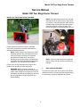
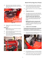
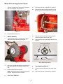
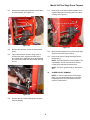
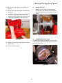
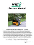
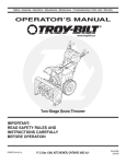
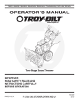
Service Manual
Model 380 Two-Stage Snow Thrower
NOTE: These materials are for use by trained technicians who are experienced in the service and repair of outdoor power
equipment of the kind described in this publication, and are not intended for use by untrained or inexperienced individuals.
These materials are intended to provide supplemental information to assist the trained technician. Untrained or
inexperienced individuals should seek the assistance of an experienced and trained professional. Read, understand, and
follow all instructions and common sense when working on power equipment. This includes the contents of the product’s
Operators Manual, supplied with the equipment. No liability can be accepted for any inaccuracies or omission in this
publication, although care has been taken to make it as complete and accurate as possible at the time of publication.
However, due to the variety of outdoor power equipment and continuing product changes that occur over time, updates will
be made to these instructions from time to time. Therefore, it may be necessary to obtain the latest materials before servicing
or repairing a product. The company reserves the right to make changes at any time to this publication without prior notice
and without incurring an obligation to make such changes to previously published versions. Instructions, photographs and
illustrations used in this publication are for reference use only and may not depict actual model and component parts. ©
Copyright 2005 MTD Products Inc. All Rights Reserved
MTD Products LLC - Product Training and Education Department
FORM NUMBER 769-01419
9/2004
Table of Contents
TOPIC
PAGE
Skid Shoe Adjustment . . . . . . . . . . . . . . . . . . . . . . . . . . . . . . . . . . . . . . . . . . . . . . . . . . 1
Skid Shoe Removal and Replacement . . . . . . . . . . . . . . . . . . . . . . . . . . . . . . . . . . . . . . 2
Shave Plate Removal and Installation . . . . . . . . . . . . . . . . . . . . . . . . . . . . . . . . . . . . . . 2
Belt Removal and Replacement . . . . . . . . . . . . . . . . . . . . . . . . . . . . . . . . . . . . . . . . . . . 2
Auger Shear Bolts . . . . . . . . . . . . . . . . . . . . . . . . . . . . . . . . . . . . . . . . . . . . . . . . . . . . . 3
Auger Cable Adjustment . . . . . . . . . . . . . . . . . . . . . . . . . . . . . . . . . . . . . . . . . . . . . . . . 3
Wheel Removal . . . . . . . . . . . . . . . . . . . . . . . . . . . . . . . . . . . . . . . . . . . . . . . . . . . . . . . 4
Drive Axle Removal . . . . . . . . . . . . . . . . . . . . . . . . . . . . . . . . . . . . . . . . . . . . . . . . . . . . 4
Transmission Removal . . . . . . . . . . . . . . . . . . . . . . . . . . . . . . . . . . . . . . . . . . . . . . . . . . 4
Auger Pulley Removal . . . . . . . . . . . . . . . . . . . . . . . . . . . . . . . . . . . . . . . . . . . . . . . . . . 5
Auger and Impeller Removal . . . . . . . . . . . . . . . . . . . . . . . . . . . . . . . . . . . . . . . . . . . . . 6
Spiral Assembly Removal . . . . . . . . . . . . . . . . . . . . . . . . . . . . . . . . . . . . . . . . . . . . . . . 7
Impeller Removal . . . . . . . . . . . . . . . . . . . . . . . . . . . . . . . . . . . . . . . . . . . . . . . . . . . . . . 8
Reducer Transmission . . . . . . . . . . . . . . . . . . . . . . . . . . . . . . . . . . . . . . . . . . . . . . . . . . 8
Reduction Transmission Disassembly . . . . . . . . . . . . . . . . . . . . . . . . . . . . . . . . . . . . . . 8
Auger Cable Replacement . . . . . . . . . . . . . . . . . . . . . . . . . . . . . . . . . . . . . . . . . . . . . . . 9
Directional Discharge Chute Assembly Removal. . . . . . . . . . . . . . . . . . . . . . . . . . . . . 10
Removal of the Auger Idler Bracket . . . . . . . . . . . . . . . . . . . . . . . . . . . . . . . . . . . . . . . 10
Engine Pulleys . . . . . . . . . . . . . . . . . . . . . . . . . . . . . . . . . . . . . . . . . . . . . . . . . . . . . . . 11
Carburetor Bowl Drain . . . . . . . . . . . . . . . . . . . . . . . . . . . . . . . . . . . . . . . . . . . . . . . . . 11
Model 380 Two Stage Snow Thrower
Service Manual
Model 380 Two Stage Snow Thrower
MODEL 380 TWO STAGE SNOW THROWER
NOTE: Some procedures require you to tip the
snow thrower up on the front of the auger housing. If there is fuel in the gas tank, place a piece
of plastic wrap over the gas tank opening and
screw the cap back on the tank tightly. This
should keep gas from leaking from the cap vent.
Disconnect Spark
Plug Wire
31A-380D000 Serial number 1F-193I40012.
Please refer to the owners manual for Assembly
Instructions, Preparation, Operation, Maintenance,
Storage and Safety precautions.
Plastic Wrap
NOTE: These materials are prepared for use by
trained technicians who are experienced in the
service and repair of this type of equipment
described in this publication, and are not
intended for use by untrained or inexperienced
individuals. All such individuals should seek the
assistance of an authorized service dealer.
NOTE: a piece of plastic wrap or the parts bag
can be used to seal the cap from possible gas
leakage.
Proper set up is very important to the long life and
problem free operation of power equipment.
1.
WARNING: Before servicing, repairing, or
inspecting, disengage all clutch levers and stop
engine. Wait until all moving parts have come to
a complete stop. Disconnect spark plug wire and
ground it against the engine to prevent unintended starting.
SKID SHOE ADJUSTMENT
To prevent excessive and uneven wear on the Shave
Plate at the bottom of the snow thrower auger housing,
it is necessary to properly adjust the Skid Shoes.
1
Model 380 Two Stage Snow Thrower
1.1.
AUGER BELT
Place a piece of carton cardboard under the
shave plate. See Figure 1.1.
4.1.
Shave Plate
Using a 5/16” socket, remove the screw securing
the right side of the belt cover to the drive housing. See Figure 4.1.
Skid Shoe
Cardboard
Belt Cover
Carriage Bolt, Bell Washer, Hex Nut
Figure 1.1
1.2.
Figure 4.1
Loosen the two carriage bolts which secure each
skid shoe to the auger housing. Lower the skid
shoes to the ground and retighten the carriage
bolts.
2.
SKID SHOE REMOVAL AND REPLACEMENT
2.1.
Remove the two carriage bolts, bell washers and
hex nuts securing the skid shoes to the auger
housing. See Figure 1.1.
2.2.
Reassemble new skid shoes with the hardware
just removed. Make sure the cupped side of the
washer goes against the skid shoe and that the
skid shoes are adjusted as described in Section
1.
3.
SHAVE PLATE REMOVAL AND INSTALLATION
3.1.
Remove both skid shoes and hardware including
carriage bolts, bell washers and hex nuts which
attach shave plate to the snow thrower housing.
See Figure 1.1.
3.2.
Reassemble new shave plate, making sure
heads of the carriage bolts are to the inside of
the housing. reinstall skid shoes and tighten
securely.
4.
Screw
4.2.
Press in on the tabs on each side of the cover
and lift upwards pulling the belt cover out from
around the engine.
4.3.
Slip the front auger belt off the engine pulley
pushing it down between the idler bracket and
the engine pulley. See Figure 4.3.
Auger Belt
Drive Belt
Figure 4.3
BELT REMOVAL AND REPLACEMENT
NOTE: There are two belts on the unit, the auger
belt and the drive belt. It is recommended that
you replace both belts at the same time.
2
Model 380 Two Stage Snow Thrower
4.4.
Squeeze the auger control bail to release the
tension on the auger belt brake; remove the belt.
See Figure 4.4.
4.8.
Pivot the transmission forward to release pressure on the drive belt and remove the belt from
around the engine pulley and transmission.
4.9.
Replace both belts in reverse order of disassembly.
5.
AUGER SHEAR BOLTS
5.1.
The augers are secured to the spiral shaft with
two shear bolts and hex lock nuts. If you hit a foreign object or ice jam, the snow thrower is
designed so that the bolts may shear. If the
augers do not turn, check if the bolts have
sheared. Two replacement shear bolts and hex
lock nuts have been provided with the snow
thrower.
Auger Idler
Auger Belt Brake
NOTE: NEVER replace the auger shear bolts
with standard hex bolts. Any damage to the
auger gearbox or other components, as a result
of doing so, will NOT be covered by your snow
thrower warranty.
Figure 4.4
4.5.
Replace with a new belt AFTER replacing the
drive belt.
6.
DRIVE BELT
Periodic adjustment to the auger control cable may be
required due to normal stretch and wear on the auger
belt. Adjustment is needed if the augers seem to
hesitate while turning, but the engine maintains speed.
NOTE: Replace the drive belt before reassembling the new auger belt.
4.6.
4.7.
AUGER CABLE ADJUSTMENT
Tip the snow thrower up and forward so that is
rests on the auger housing.
6.1.
Remove the spring that connects the transmission to a bolt on the right hand side of the engine
frame. See Figure 4.7.
Remove the screw securing the belt cover to the
right side of the housing. See Figure 6.1.
Recoil rope eases removal
Belt Cover
Screw
Extension Spring
Transmission
Figure 6.1
Figure 4.7
3
6.2.
Press the tabs that secure it to the snow thrower
housing. Remove the belt cover and set it aside.
6.3.
You can now access the auger cable. Adjust the
two hex nuts on the auger cable towards the
Model 380 Two Stage Snow Thrower
spring to increase the tension on the auger belt
when it is engaged. See Figure 6.3.
8.1.
Remove the wheels as described in section 7.
8.2.
Remove the cotter pin and clevis pin securing
the 70T gear to the axle shaft. See Figure 8.2.
Cotter Pin an Clevis Pin
Adjustment Hex Screws
Axle Shaft
Idler Arm
Auger Cable
70T Gear
Figure 6.3
Figure 8.2
6.4.
Reassemble the belt cover.
7.
WHEEL REMOVAL
7.1.
Tip the snow thrower up and forward so that it
rests on the auger housing. See Figure 7.1.
8.3.
Slide the axle from the drive housing as you
remove the gear from the axle shaft.
8.4.
Remove the hex flange bearings from the drive
housing.
Hex Flange Bearings
70T Gear
Lock Bolt and Bell Washer
Axle Shaft
Figure 7.1
7.2.
7.3.
Clevis Pin
Drive Axle Components
Using a 1/2” socket and ratchet, remove the lock
bolt and bell washer securing the wheel to the
axle.
9.
TRANSMISSION REMOVAL
9.1.
Tip the unit up and forward on the auger housing.
9.2.
Remove the wheels as described in section 7.
Remove the wheel from the axle.
NOTE: The wheel hubs are made from a special
polymer. They will not rust or corrode.
8.
Cotter Pin
DRIVE AXLE REMOVAL
4
Model 380 Two Stage Snow Thrower
9.3.
Remove the tension spring attached to the frame
and transmission. See Figure 9.3.
9.7.
Remove the cotter pins and flat washers securing the transmission mounting axle to the drive
housing. See Figure 9.7.
Extension Spring
Transmission
Cotter Pins and Flat Washers
Transmission Pulley
Figure 9.3
Figure 9.7
9.4.
9.5.
Remove the belt from around the transmission
pulley.
Tip the transmission forward. Using a pair of
needle nose pliers, squeeze the tabs on the
drive cable where it attaches to the transmission
and remove the cable from the bracket. See Figure 9.5.
9.8.
Move the transmission to the left and to the right
and pivot it from the drive housing.
9.9.
Remove the two hex flange bearings from the
drive housing.
NOTE: The transmission is not serviceable. The
transmission must be returned to the factory
unopened for warranty reimbursement.
Drive Cable Spring
NOTE: The pinion gear and roll pin are serviceable.
Drive Cable Tabs
10.
AUGER PULLEY REMOVAL
NOTE: In order to ease removal of the auger
pulley it is recommended that you remove the
transmission first. See transmission removal
section for instructions.
Pliers
Figure 9.5
9.6.
Remove the drive cable Z fitting from the transmission housing.
5
Model 380 Two Stage Snow Thrower
11.3. Remove the Auger Pulley. Refer to Section 10.
10.1. Using a ½” socket and ratchet, remove the lock
bolt securing the auger pulley to the auger gearbox drive shaft. See Figure 10.1.
11.4. Using a 1/2” socket, remove the three hex nuts
and lock washers securing the bearing housing
to the auger housing. Set the bearing housing
aside. See Figure 11.4.
Lock Bolt
Bearing Housing
Auger Pulley
Figure 10.1
Hex Nuts and Lock Washers
NOTE: Use a drive belt to apply pressure to the
auger pulley and hold in place during removal of
the lock bolt.
Figure 11.4
NOTE: The order of parts in this group are bearing housing, bearing, shim and spacer.
10.2. Inspect the idler arm, flat idler pulley, tension
spring and cable for proper operation. Lubricate
between the idler arm and auger housing at any
point of contact. See Figure 10.2.
Tension Spring and Cable
11.5. Tip the unit back and down so it rests on the
drive housing.
11.6. Using a 1/2” socket, remove the six AB Screws
and bell washers securing the auger assembly
to the sides of the auger housing. See Figure
11.6.
Flat Idler Pulley
Extension Spring
Lubricate under idler arm
Figure 10.2
11.
AB Screws
AUGER AND IMPELLER REMOVAL
Figure 11.6
11.1. Remove the wheels to ease removal of the
transmission. See section 7.
11.2. Remove the Transmission. Refer to Section 9.
6
Model 380 Two Stage Snow Thrower
11.7. Remove the complete auger assembly from the
auger housing. See Figure 11.7.
12.
SPIRAL ASSEMBLY REMOVAL
12.1. Remove the auger and impeller assembly from
the housing. Refer to Section 11.
12.2. Using a 1/2” socket and a box end wrench,
remove the hex lock nut and shear bolt from the
spiral assembly and auger drive shaft. See Figure 12.2.
Auger Assembly
Hex Lock Nut and Shear Bolt
Hex Flange Bearing and Bearing Housing
Figure 11.7
11.8. Inspect the hex flange bearings and bearing
housings for any wear or damage
11.9. If not removed previously, remove the shim and
spacer from the worm shaft. See Figure 11.9.
Figure 12.2
12.3. Slide the spiral augers off the shaft and mark the
spiral for left or right side.
NOTE: It is possible to install the auger spirals
backwards. If necessary, refer to the illustrated
parts diagram for proper orientation.
NOTE: During disassembly note the location of
the flat washer on the gearbox side of the spiral
and flange bushings on both ends of the spiral.
Shim and Spacer on Worm Shaft
Figure 11.9
NOTE: The auger housing holes are elongated
to allow auger alignment during reassembly.
NOTE: When reassembling be careful not to
over torque and strip the bearing hub housing
holes.
7
Model 380 Two Stage Snow Thrower
13.
14.
IMPELLER REMOVAL
REDUCER TRANSMISSION
13.1. Remove the auger and impeller as described in
Section 11.
14.1. The reducer can be serviced. It can also be purchased as an assembly. See Figure 14.1.
13.2. Using a 3/16 punch and hammer, remove the
front spiral pin securing the impeller to the worm
shaft. See Figure 13.2.
NOTE: On the top of the gearbox is inspection
and access hole for adding grease when and if
required. Remove the rubber grommet from the
lubrication port.
Impeller
Rubber Grommet
Spiral Pin
Reducer Transmission
Figure 13.2
Figure 14.1
13.3. Slide the impeller on the worm shaft towards the
reducer housing to gain access to the rear spiral
pin.
15.
13.4. Using a 3/16 punch and hammer, remove the
rear spiral pin. See Figure 13.4.
REDUCTION TRANSMISSION DISASSEMBLY
15.1. Using a 3/8” socket, remove the 5 TT screws
securing the reducer halves together. See Figure 15.1.
Rear Spiral Pin
5 TT Screws
Figure 13.4
Figure 15.1
13.5. Remove the impeller from the worm shaft.
8
Model 380 Two Stage Snow Thrower
15.2. Separate the housing halves using a putty knife.
See Figure 15.3.
16.2. Spin the inner nut off the end of the control cable
and slide the cable out of the bracket.
15.3. Inspect all internal parts for wear or damage.
16.3. Remove the spring from the auger bracket.
16.4. Using a ½” inch socket and a ½” inch box
wrench loosen the hex nut securing the cable
bracket to the left hand handle bar. See Figure
16.4.
Cable bracket
Ultra Gray
Figure 15.3
NOTE: before assembly, clean off all of the ultragray sealant on both sides of the gearbox housing. Use ultra gray to reseal the housing before
assembly.
Figure 16.4
16.5. Remove the cable from the bracket and remove
the “Z” fitting from the bail.
16.
AUGER CABLE REPLACEMENT
16.6. Slide the cable through the plastic tie and plastic
mounting grommet on the frame.
16.1. Using two 7/16”inch wrenches loosen the two
hex nuts attaching the auger control cable to the
bracket on the left hand drive housing. See Figure 16.1.
16.7. Replace in the reverse order of disassembly.
Hex Nuts
Auger Control Cable
Figure 16.1
9
Model 380 Two Stage Snow Thrower
17.
17.3. Pry the lower inner clasp to release the collar.
See Figure 17.3.
DIRECTIONAL DISCHARGE CHUTE ASSEMBLY REMOVAL.
17.1. Turn the discharge chute until it faces to the
right. See Figure 17.1.
Lower Clasp
Figure 17.3
Discharge chute facing right
Figure 17.1
17.4. Remove the collar.
17.5. Lift off the discharge chute
17.2. Using a screwdriver, pry the clasp on the chute
assembly collar to release the clasp. See Figure
17.2.
NOTE: During assembly make sure to position
the collar into the detent spring. Take time to fit
upper and lower flanges on the collar around the
chute flanges. This will fit without forcing.
Chute Collar
Chute Collar
Clasp
Detent Spring
Figure 17.2
Assembly Detail
18.
REMOVAL OF THE AUGER IDLER BRACKET
18.1. Remove the belts as described in Section 4.
18.2. Remove the wheels as described in Section 7.
18.3. Remove the transmission as described in Section 9.
10
Model 380 Two Stage Snow Thrower
19.
18.4. Remove the auger pulley as described in Section 10.
ENGINE PULLEYS
NOTE: If there is reason to disassemble the
engine pulleys, pay attention to the shape and
orientation of the pulleys and spacers for reassembly.
18.5. Remove the auger and impeller as described in
Section 11.
18.6. Using a 15/16” socket on the Idler side and a 9/
16” socket on the impeller side, remove the
shoulder screw and flange lock nut securing the
idler to the auger housing. See Figure 18.6.
Auger Pulley
Shoulder Screw
(Flange Lock Nut on
underside of housing)
Drive Pulley
20.
Figure 18.6
CARBURETOR BOWL DRAIN
This model has a spring loaded drain for the float bowl.
It can be used to drain water or old fuel from the float
bowl. See Figure 20.0.
18.7. Disconnect the extension spring from the idler to
the housing.
18.8. Remove the Idler bracket.
Carburetor Bowl Drain
Figure 20.0
11