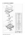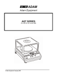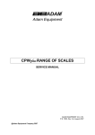
1
.
Adam Equipment
CBK SERIES
Service Manual
Software Rev.: 4.28 & above
4.25H & above for CBK 8H/16aH
ADAM EQUIPMENT CO. LTD.
P.N. 8735, Rev. A3, August 2007
© Adam Equipment Company 2007
© Adam Equipment Company 2007
CONTENTS
1.0
INTRODUCTION ...................................................................................................... 3
2.0
SPECIFICATIONS.................................................................................................... 4
3.0
TROUBLESHOOTING ............................................................................................. 6
4.0
ERROR CODES....................................................................................................... 7
5.0
CBK DESCRIPTION................................................................................................. 8
6.0
LOAD CELL DAMAGE ............................................................................................. 8
7.0
FACTORY PARAMETERS..................................................................................... 12
7.1
7.2
7.3
7.4
7.5
7.6
7.7
7.8
7.9
F1 -CALIBRATION ............................................................................................... 13
F2 -RESOLUTION ............................................................................................... 14
F3 – CAPACITY ................................................................................................... 14
F4 -INITIAL ZERO RANGE .................................................................................. 14
F5 -RE-ZERO RANGE ......................................................................................... 15
F6 -SUCCESSIVE TARE ..................................................................................... 15
F7 -A/D COUNT.................................................................................................... 15
F8 –ZERO............................................................................................................ 16
F9 –LOW VOLTAGE DETECTION ...................................................................... 16
8.0
WIRING DIAGRAM ................................................................................................ 17
9.0
MECHANICAL ASSEMBLY.................................................................................... 18
*****
© Adam Equipment Company 2007
1
© Adam Equipment Company 2007
2
1.0 INTRODUCTION
•
The CBK range of scales provides an accurate, fast and versatile general
purpose weighing scales with parts counting, percent weighing and checkweighing functions.
•
There are two series within the range. The CBKa series are similar to the
CBK series except the CBKa scales can operate in both imperial and metric
weighing units, whereas for the CBK series the imperial units are not
available.
•
All models have LEDs to indicate when a weight is below the low limit,
between the limits or above the high limit next to the display. These can
work in conjunction with an audible alarm for check weighing as well as LCD
showing LO, OK and HI.
•
All scales have stainless steel weighing platforms on an ABS base assembly.
•
They are supplied with a RS-232 bi-directional interface and real time clock
(RTC).
•
The scales have sealed keypads with colour coded membrane switches and
a large easy to read liquid crystal type display (LCD) supplied with a
backlight.
•
They include automatic zero tracking, semi-automatic & pre-set tare,
accumulation facility that allows the weight to be stored and recalled as an
accumulated total.
© Adam Equipment Company 2007
3
2.0 SPECIFICATIONS
CBK 4
CBK 8H
CBK 8
CBK 16
CBK 32
CBK 48
Maximum Capacity
4 kg
8 kg
8 kg
16 kg
32 kg
48 kg
Tare Range
-4 kg
-8 kg
-8 kg
-9.9995 kg
-32 kg
-48 kg
Readability
0.0001 kg
0.0001 kg
0.0002 kg
0.0005 kg
0.001 kg
0.002 kg
Repeatability (S.D.)
0.0001 kg
0.0001 kg
0.0002 kg
0.0005 kg
0.001 kg
0.002 kg
Linearity (±)
0.0002 kg
0.0002 kg
0.0004 kg
0.001 kg
0.002 kg
0.004 kg
Maximum Capacity
4000 g
8000 g
8000 g
16000 g
32000 g
48000 g
Tare Range
-4000 g
-8000 g
-8000 g
-9999.5 g
-32000 g
-48000 g
Readability
0.1 g
0.1 g
0.2 g
0.5 g
1g
2g
Repeatability (S.D.)
0.1 g
0.1 g
0.2 g
0.5 g
1g
2g
Linearity (±)
0.2 g
0.2 g
0.4 g
1g
2g
4g
Kilograms
Grams
CBKa Series (USA models)
CBK 8a
CBK 16aH
CBK 16a
CBK 35a
CBK 70a
CBK 100a
Maximum Capacity
8 lb
16 lb
16 lb
35 lb
70 lb
100 lb
Tare Range
-8 lb
-9.9995 lb
-9.9995 lb
-35 lb
-70 lb
-99 lb
Readability
0.0002 lb
0.0002 lb
0.0005 lb
0.001 lb
0.002 lb
0.005 lb
Repeatability (S.D.)
0.0002 lb
0.0002 lb
0.0005 lb
0.001 lb
0.002 lb
0.005 lb
Linearity (±)
0.0004 lb
0.0004 lb
0.001 lb
0.002 lb
0.004 lb
0.01 lb
Maximum Capacity
128 oz
256 oz
256 oz
560 oz
1120 oz
1600 oz
Readability
0.005 oz
0.005 oz
0.01 oz
0.02 oz
0.05 oz
0.1 oz
Repeatability (S.D.)
0.005 oz
0.005 oz
0.01 oz
0.02 oz
0.05 oz
0.1 oz
Linearity (±)
0.01 oz
0.01 oz
0.02 oz
0.04 oz
0.1 oz
0.2 oz
8 lb:
16 lb:
16 lb:
35 lb:
70 lb:
99 lb:
0.0 oz
0.0 oz
0.0 oz
0.0 oz
0.0 oz
15.9 oz
Display shows
8:_16.00
16:_16.0
16:_16.0
35:_16.0
70:_16.0
99:_16.0
Readability
0.01 oz
0.1 oz
0.1 oz
0.1 oz
0.1 oz
0.1 oz
Repeatability (S.D.)
0.01 oz
0.1 oz
0.1 oz
0.1 oz
0.1 oz
0.1 oz
Linearity (±)
0.02 oz
0.2 oz
0.2 oz
0.2 oz
0.2 oz
0.2 oz
Pounds
Ounces
Pounds:Ounces
Maximum Capacity
© Adam Equipment Company 2007
4
Kilograms
Maximum Capacity
4 kg
8 kg
8 kg
16 kg
32 kg
48 kg
Readability
0.0001 kg
0.0001 kg
0.0002 kg
0.0005 kg
0.001 kg
0.002 kg
Repeatability (S.D.)
0.0001 kg
0.0001 kg
0.0002 kg
0.0005 kg
0.001 kg
0.002 kg
Linearity (±)
0.0002 kg
0.0002 kg
0.0004 kg
0.001 kg
0.002 kg
0.004 kg
Maximum Capacity
4000 g
8000 g
8000 g
16000 g
32000 g
48000 g
Readability
0.1 g
0.1 g
0.2 g
0.5 g
1g
2g
Repeatability (S.D.)
0.1 g
0.1 g
0.2 g
0.5 g
1g
2g
Linearity (±)
0.2 g
0.2 g
0.4 g
1g
2g
4g
Grams
OTHER SPECIFICATIONS
CBK Series- kg, g
CBKa Series- kg, g, lb, oz, lb:oz
RS-232 bi-directional Interface
Units of measure
Interface
Stabilisation Time
Operating Temperature
Power supply
Battery
2 Seconds typical
-10°C to 40°C
14°F to 104°F
230 VAC 50/60 Hz
115 VAC available
Internal rechargeable battery (~90 hours operation)
Calibration
Automatic External
Display
6 digits LCD digital display
with capacity tracker and symbols for units
Scale Housing
ABS Plastic, Stainless Steel platform
Pan Size
225 x 275 mm
8.9” x 10.8”
Overall Dimensions
(wxdxh)
315 x 355 x 110 mm
12.4” x 14” x 4.3”
Net Weight
4.1 kg
9 lb
Applications
Weighing Scales
Functions
Weighing, Parts counting, % weighing, Check weighing,
Check counting, Accumulation of weights
Date/Time
Real Time Clock (RTC),
To print date and time information- battery backed
* For USA models, ”lb” is always enabled when the power is turned on and are calibrated in “lb” unit.
© Adam Equipment Company 2007
5
3.0 TROUBLESHOOTING
PROBLEM
POSSIBLE CAUSE
Display is blank
Power Switch faulty or not connected
No turn on test
Battery not charged or faulty
Power supply faulty or incorrect type
“- - - - - -“appears on display
Maximum capacity exceeded
Load Cell damaged
Electronics is faulty
Display is unstable
Drafts or air currents
Obstruction under pan
Sample is moving (animal weighing)
Vibrations through table
Temperature changed dramatically
Electronics faulty or Battery low
Weight value incorrect
Calibration error, Recalibrate
Unit calibrated with inaccurate weight
Balance not level
Obstruction between sample pan
Wrong unit of weight displayed
Cannot use Full Capacity
Over-load Stops hitting pan support or hitting
bottom of load cell
Electronics faulty
Parameters set incorrectly
Load Cell Damaged
Not Linear
Overload stops hitting too soon
Faulty factory calibration
© Adam Equipment Company 2007
6
Off Centre Loading error
Overload Stops not correct
Obstruction under pan
Battery will not charge
Charging circuit failure
Battery Failure
Incorrect adapter (below 800 mA)
Processor failure
4.0 ERROR CODES
ERROR
CODE
DESCRIPTION
POSSIBLE CAUSES
Err 1
Time input Error
Invalid time entry such as “268970” for
the time format “H-m-S”.
Err 2
Err 4
Date input Error
34th day of a month is an invalid entry.
Initial Zero is greater than
allowed (4% of maximum
capacity) when power is turned
on or when the [Zero/Enter]
key is pressed.
Weight on the pan when turning the
scale on.
Excessive weight on the pan when
zeroing the scale.
Platform is not installed.
Improper calibration of the scale.
Damaged load cell.
Damaged Electronics.
Err 6
A/D count is not correct when Load cell is damaged.
turning the scale on.
Electronics is damaged.
Err 7
Percent input error
Percent function is entered with no
reference mass on the pan.
Err 8
High limit input error
Low limit is set first, then the high limit is
set lower than the low limit and high
limit not equal to zero.
Err 9
Low limit input error
High limit is set first, then the low limit is
set higher than the high limit and low
limit not equal to zero.
FAIL H or
FAIL L
Calibration error
Improper calibration (should be within
+10% of the factory calibration). The old
calibration data will be retained until the
calibration process is complete.
© Adam Equipment Company 2007
7
5.0 CBK DESCRIPTION
The CBK scales have an enclosure with all components mounted within it. To gain access
to the components remove the 5 screws securing the cover to the base.
The basic unit consists of:
Base
Load Cell frame
Power switch
Main PCB assembly
Battery
Display PCB assembly
Keypad
All models of CBK are similar except the selection of load cells and the program.
Normally if a problem is found with a circuit board the most cost effective method of
solving the problem is to replace the circuit board.
The main PCB assembly includes:
A/D converter (AU1),
Microprocessor (DU1) and
Power supply/battery charger circuits (DU5, T2).
NOTE: The wiring instruction for the transformerInput Voltage
Wires
230 VAC, 50/60 Hz
Red & Yellow
115 VAC, 50/60 Hz
Blue & Yellow
6.0 LOAD CELL DAMAGE
The most common reason a scale fails is that the load cell has been damaged. The
damage can be from 2 primary causes. The first is physical damage due to an overload or
an impact from the side and the second is damage due to the environment, such as
moisture, extreme heat or a cut cable if the cables are exposed.
© Adam Equipment Company 2007
8
PRINCIPLE OF OPERATION
The stain gauge load cell is a method of measuring the amount of stress put onto a metal
structure due to a weight being supported by the structure. The stress is measured using
4 strain gage sensors mounted in a particular way on the metal structure.
These 4 strain gauges are connected in such a way that they form a wheatstone bridge.
See figure below. In the simplest load cells there are only the 4 resistances of the strain
gages to consider. Normally without a load on the load cell all the resistances are the
same. However when the load cell has a weight on it 2 of the strain gages will be in
compression (A and D) and the resistance will decrease and 2 will be in tension (B and C)
and their resistance will increase.
+E
+E
A
A
B
10 VOLT POWER
SUPPLY
+S
9
34
m
oh
+S
-S
34
m
m
C
D
oh
oh
35
0
1
35
0
35
oh
m
-S
C
B
m
oh
m
oh
1
35
0
m
oh
35
0
35
10 VOLT POWER
SUPPLY
Vout = O VOLTS,
9
m
oh
D
Vout = 0.028 VOLTS (28mv),
BETWEEN +S AND -s
BETWEEN +S AND -s
-E
-E
UNBALANCED BRIDGE
FULL CAPACITY LOAD
ON THE LOAD CELL
BALANCED BRIDGE
This will cause the bridge to become unbalanced. When the bridge has a voltage across it
from +E to -E then the signal output at +S and -S will show a voltage of zero volts with no
load and a small voltage proportional to the load as the load is increased. Typical load
cells show 20-30mv of signal if the excitation voltage is 10volts and the load cell is fully
loaded.
Most load cells used in scales are not as simple as this example. They have additional
resistance elements added to compensate for temperature variations and to set the
outputs to correct voltages. The circuit of a typical load cell is shown below-
© Adam Equipment Company 2007
9
A method to check the basic function and integrity of a load cell can be done using a
ohmmeter and voltmeter with up to a 10volt power supply.
Before the load cell is connected to the power supply use the ohmmeter to measure the
resistance between the wires. Typical resistance values are:
+E to -E
410 ohms ±30 ohms
+S to -S
350 ohms ± 2 ohms
+E to +S or any other combination similar approximately 270 ohms.
If the load cell has Sense connections in addition they are connected to the excitation
internal to the load cell.
Connect the load cell +E and -E to a power supply, typically 10 volts. Never use more
than 12 volts as it may damage the load cell.
Measure the voltage between +S and -S.
With no load the voltage should be approximate 0mv ±3mv.
With a mass on the load cell the output voltage should increase. The amount by which it
increases will be dependent upon the sensitivity of the load cell, capacity of the load cell,
the excitation voltage and the amount of mass placed on the load cell. Most load cells
have a sensitivity of either 2mv/V or 3mv/V.
© Adam Equipment Company 2007
10
The expected change to the output is:
Vout = (2mv/V) * Vext * Mass
capacity of load cell
For example a 2mv/V load cell of 30Kg capacity with 20Kg placed on it. Vext is 5 volts
would give a output of approximately:
Vout = (2mv/V) * Vext * Mass
capacity of load cell
= 2mv/V * 5V * 20Kg = 6.7mv
30kg
If the load cell has been damaged the no load voltage will likely be greater than 3mv or the
loaded voltage will be grossly different from the expected value. Remember the loaded
voltage will be offset by the amount of zero load voltage measured.
The load cell can be tested while it is connected to the A/D converter circuit board, using
the scale power supply for excitation voltage.
TESTING LOAD CELLS IN THE SCALE
The signal from the load cells is amplified by the circuits on the A/D circuit board. The
signal needs to be amplified to make it acceptable for the A/D converter used. The CBK-M
scales amplify the input by 200 and change the no load voltage to about +2.5V. The
amplified and offset voltage is measured at pin 6 of IC7, the INA118P amplifier IC. This
voltage is sent to the filter and then to the A/D converter.
© Adam Equipment Company 2007
11
7.0 FACTORY PARAMETERS
The factory parameters are used for setting the capacity and basic settings.
Switch off the scale and then switch on again. Press [Tare] during the initial self-test.
The display will ask for a code number, “P _ _ _ _ “.
Enter the number 2006 and press [Tare].
The display will show the first parameter “F1 CAL”. To scroll through other parameters
press the [Func] key.
The display will show the parameter number then the word describing the function.
Press the [Tare] key to enter a parameter.
Press the [Zero] key to exit a parameter. Pressing [Zero] again will return the scale to
weighing.
When a parameter is entered by pressing the [Tare] key, the display will guide you
through the parameter selected and the options available.
The parameters available are:
F1
F2
F3
F4
F5
F6
F7
F8
F9
CAL
rES
CAP
int
rE Z
SCS
Cnt
ZE M
Ld M
To enter the Calibration
Resolution selection, not valid for approved units
Select Capacity
Initial Zero Range
Re-Zero Range
Successive Tare Enable
Display the A/D counts
Set zero method
Set low voltage detect mode
© Adam Equipment Company 2007
12
7.1
F1 -CALIBRATION
To enter the calibration parameter, press the [Tare] key when “F1 CAL” is displayed.
The display will instruct you to remove any weight from the scale, “UnloAd”. Press [Tare].
NOTE: USA models are calibrated using “lb” unit.
The display will tell you to add the first weight to the scale: “Ld 1 OO kg”
Place the first calibration weight as suggested in the Table below. Wait for stability then
press the [Tare] key.
The display will tell you to add the second weight to the scale: “Ld 2 00 kg”
Place the second calibration weight as suggested in the Table below. Wait for stability then
press the [Tare] key.
The display will show “PASS” if the calibration is OK. Or it will show “FAIL L” if calibration
could not be completed correctly.
Remove the calibration weight. The scale will return to weighing.
Suggested Calibration Weights:
Models
Calibration weight 1 Calibration Weight 2
CBK 4 / CBK 8a
CBK 8 / CBK 16a
CBK 16 / CBK 35a
CBK 32 / CBK 70a
CBK 48 / CBK 100a
2 kg / 2 lb
4 kg / 5 lb
5 kg / 10 lb
10 kg / 20 lb
20 kg / 40 lb
© Adam Equipment Company 2007
4 kg / 5 lb
7 kg / 10 lb
15 kg / 30 lb
30 kg / 50 lb
40 kg / 70 lb
13
7.2
F2 -RESOLUTION
NOTE: This value can not be changed for the CBK scales.
7.3
F3 – CAPACITY
To enter this parameter, press the [Tare] key when “F3 CAP” is shown.
The display will show the current capacity.
Press the [Func] key to scroll through the options.
Press [Tare] to accept the displayed value and return to the parameter or press the [Zero]
key to return to the parameter without changing the value.
Then press [Func] to advance to the next parameter.
NOTE: The scale must be originally built for the capacity selected. The 4 kg unit uses the
5 kg load cells, 8 kg unit uses 10 kg load cells, the 16 kg unit uses 20 kg load cells, the 32
kg unit uses 35 kg load cells and the 48 kg unit uses 50 kg load cells.
7.4
F4 -INITIAL ZERO RANGE
To enter this parameter, press the [Tare] key when “F4 int” is shown.
The display will show the current initial zero range.
Press the [Func] key to scroll through the options.
Press [Tare] to accept the displayed value and return to the parameter or press the [Zero]
key to return to the parameter without changing the value.
Then press [Func] to advance to the next parameter.
© Adam Equipment Company 2007
14
7.5
F5 -RE-ZERO RANGE
To enter this parameter, press the [Tare] key when “F5 reZ” is shown.
The display will show the current re-zero range.
Press the [Func] key to scroll through the options.
Press [Tare] to accept the displayed value and return to the parameter or press the [Zero]
key to return to the parameter without changing the value.
Then press [Func] to advance to the next parameter.
7.6
F6 -SUCCESSIVE TARE
To enter this parameter, press the [Tare] key when “F6 SCS” is shown.
The display will show if the successive tare is “tr on” or “tr oFF”.
Press the [Func] key to scroll through the options.
Press [Tare] to accept the displayed value and return to the parameter or press the [Zero]
key to return to the parameter without changing the value.
Then press [Func] to advance to the next parameter.
7.7
F7 -A/D COUNT
To enter this parameter, press the [Tare] key when “F7 Cnt” is shown.
This parameter allows you to view the A/D counts from the internal A/D converter. This can
be an aid to service.
© Adam Equipment Company 2007
15
Press the [Tare] key to return to the PARAMETER menu.
Typical value at zero is 30,000-90,000 (approx.)
Typical value at full capacity is 500,000 (approx.)
7.8
F8 –ZERO
This parameter allows the normal method of setting zero.
To enter this parameter, press the [Tare] key when “F8 ZE M” is shown.
The display will show the current settings, “modE 1” or “modE 2”.
Press the [Func] key to scroll through the options.
Press [Tare] to accept the displayed value and return to the parameter or press the [Zero]
key to return to the parameter without changing the value.
Then press [Func] to advance to the next parameter.
7.9
F9 –LOW VOLTAGE DETECTION
This parameter allows detection of low voltage when the battery wears down.
To enter this parameter, press the [Tare] key when “F9 Ld M” is shown.
The display will show if the LVD Mode is set to on or oFF.
Press the [Func] key to scroll through the options.
Press [Tare] to accept the displayed value and return to the parameter or press the [Zero]
key to return to the parameter without changing the value.
Then press [Func] to advance to the first parameter.
© Adam Equipment Company 2007
16
8.0 WIRING DIAGRAM
© Adam Equipment Company 2007
17
9.0 MECHANICAL ASSEMBLY
© Adam Equipment Company 2007
18
Manufacturer’s Declaration of Conformity
This product has been manufactured in accordance with the harmonised European standards,
following the provisions of the below stated directives:
Electro Magnetic Compatibility Directive 89/336/EEC
Low Voltage Directive 73/23/EEC
Adam Equipment Co. Ltd.
Bond Avenue, Denbigh East
Milton Keynes, MK1 1SW
United Kingdom
FCC COMPLIANCE
This equipment has been tested and found to comply with the limits for a Class A digital device,
pursuant to Part 15 of the FCC Rules. These limits are designed to provide reasonable protection
against harmful interference when the equipment is operated in a commercial environment. The
equipment generates, uses, and can radiate radio frequency energy and, if not installed and used in
accordance with the instruction manual, may cause harmful interference to radio communications.
Operation of this equipment in a residential area is likely to cause harmful interference in which case
the user will be required to correct the interference at his own expense.
Shielded interconnect cables must be employed with this equipment to insure compliance with the
pertinent RF emission limits governing this device.
Changes or modifications not expressly approved by Adam Equipment could void the user's authority
to operate the equipment.
WEEE COMPLIANCE
Any Electrical or Electronic Equipment (EEE) component or assembly of parts intended to be
incorporated into EEE devices as defined by European Directive 2002/95/EEC must be recycled or
disposed using techniques that do not introduce hazardous substances harmful to our health or the
environment as listed in Directive 2002/95/EC or amending legislation. Battery disposal in Landfill
Sites is more regulated since July 2002 by regulation 9 of the Landfill (England and Wales)
Regulations 2002 and Hazardous Waste Regulations 2005. Battery recycling has become topical and
the Waste Electrical and Electronic Equipment (WEEE) Regulations are set to impose targets for
recycling.
@Adam Equipment Company 2007
ADAM EQUIPMENT is an ISO 9001:2000 certified global company with more than 35
years experience in the production and sale of electronic weighing equipment.
Adam products are predominantly designed for the Laboratory, Educational, Medical,
retail and Industrial Segments. The product range can be described as follows:
-Analytical and Precision Balances
-Compact and Portable Balances
-High Capacity Balances
-Moisture analysers / balances
-Mechanical Scales
-Counting Scales
-Digital Weighing/Check-weighing Scales
-High performance Platform Scales
-Crane scales
-Medical Scales
-Retail Scales for Price computing
For a complete listing of all Adam products visit our website at
www.adamequipment.com
© Copyright by Adam Equipment Co. Ltd. All rights reserved. No part of this publication
may be reprinted or translated in any form or by any means without the prior permission of
Adam Equipment.
Adam Equipment reserves the right to make changes to the technology, features,
specifications and design of the equipment without notice.
All information contained within this publication is to the best of our knowledge timely,
complete and accurate when issued. However, we are not responsible for
misinterpretations which may result from the reading of this material.
The latest version of this publication can be found on our Website.
www.adamequipment.com
@Adam Equipment Company 2007