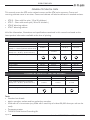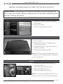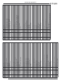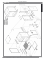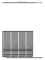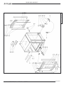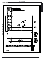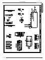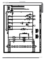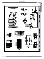
1
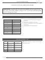
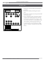
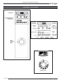
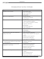
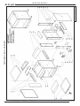
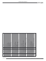
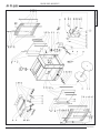
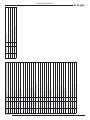
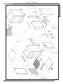
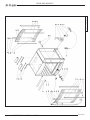
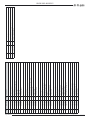
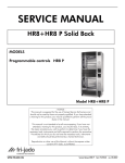
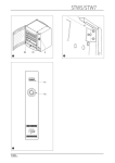
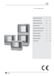
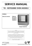
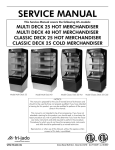
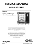
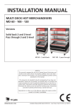
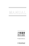
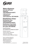
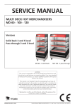
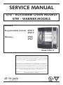
SERVICE MANUAL
STG - ROTISSERIE OVEN MODELS
STW - WARMER MODELS
MODELS
Programmable controls STG5 P
STG7 P
Warmers
STW5
STW7
Model STG7 P
- NOTICE This manual is prepared for the use of trained Service Technicians and
should not be used by those not properly qualified. If you have attended
a trianing for this product, you may be qualified to perform all the procedures in this manual.
This manual is not intended to be all encompassing. If you have not
attended a training for this product, you should read, in its entirety, the
repair procedure you wish to performto determine if you have the necessary tools, instruments and skills required to perform the procedure.
Procedures for which you do not have the necessary tools, instruments
and skills should be performed by a trained technician.
Reproduction or other use of this Manual, without the express written
consent of Fri-Jado, is prohibited.
WWW.FRIJADO.COM
Service Manual STG5/7 STW5/7 form 9123647 rev. 11/2005
Page 2 of 47
Service Manual STG5/7 STW5/7 form 9123647 rev. 11/2005
TABLE OF CONTENTS
General technical data .................................................................................................... 3
Technical Data U.S. Standard Models .................................................................................................3
Technical Data U.S. Special Models....................................................................................................3
Removal and replacement of parts for the STG5 and STG7 ............................................. 4
Right or left side panel ......................................................................................................................4
Top cover .........................................................................................................................................4
Knob................................................................................................................................................4
Instrument panel...............................................................................................................................5
Electric panel ....................................................................................................................................5
Display ............................................................................................................................................6
Panel and foil assembly.....................................................................................................................6
Namepanel ......................................................................................................................................6
Quartz lamp ....................................................................................................................................7
Power section ...................................................................................................................................7
High limit thermostat ........................................................................................................................8
Main switch ......................................................................................................................................8
Magnetic switch ................................................................................................................................9
Blower motor....................................................................................................................................9
Blower motor bottom rotisserie (stacked stg) .....................................................................................10
PT550 sensor .................................................................................................................................10
Heating element .............................................................................................................................11
Drive motor ....................................................................................................................................11
Door adjustment (left side) ..............................................................................................................12
Door glass inside ............................................................................................................................12
Door glass outside ..........................................................................................................................13
Removal and replacement of parts for the STW5 and STW7 .......................................... 14
Blower motor..................................................................................................................................14
Thermometer..................................................................................................................................14
Thermostat .....................................................................................................................................15
Main switch ....................................................................................................................................15
Heating element .............................................................................................................................16
Halotherm lamp .............................................................................................................................16
Electrical tests and service procedures ........................................................................... 17
PT500 Sensor test ...........................................................................................................................17
Heating element test .......................................................................................................................17
Keypad test ....................................................................................................................................18
Control location .............................................................................................................................19
Troubleshooting the STG5/7 Rotisserie .......................................................................... 20
Troubleshooting the STW5/7 Warmer ............................................................................ 21
Exploded views & Partlists ............................................................................................. 22
Electrical diagrams ........................................................................................................ 38
Service Manual STG5/7 STW5/7 form 9123647 rev. 11/2005
Page 3 of 47
GENERAL TECHNICAL DATA
GENERAL TECHNICAL DATA
This manual covers the STG series rotisserie ovens and the STW series warmers. Ovens and
warming cabinets come in two sizes. Ovens and cabinets will also be delivered in stacked versions.
•
•
•
•
STG 5 – Oven with five spits ( 15 to 20 chickens )
STG 7 – Oven with seven spits ( 28 to 35 chickens )
STW 5 Warming cabinet.
STW 7 Warming cabinet.
All of the information, illustrations and specifications contained in this manual are based on the
latest product information available at the time of printing.
TECHNICAL DATA U.S. STANDARD MODELS
Type
Power
Fuses needed with power connection
208 V, 3 ~ 60 Hz (3 phases without zero)
STG 5
6100W
STW 5
2500W
STG 7
9500W
STW7
3300W
3x 20 A
-
3x 35 A
3x 15 A
_
_
Fuses needed with power connection
208 V, 1N ~ 60 Hz (1 phase with zero)
Standard plug from factory
_
1x 15 A
NEMA 15-30P
G
NEMA 6-15P
NEMA 15-50P
NEMA 15-15P
G
G
G
Z
X
Z
X
Z
X
Y
Net weight
Gross weight
Height
Width
Depth
Y
Y
Stacked STG/STW cabinets: each cabinet comes with separate power cord!!
269 lbs.
220 lbs.
399 lbs.
350 lbs.
269 lbs.
478 lbs.
33 7/8”
33 7/8”
40”
32 9/16”
32 9/16”
38 13/16”
25 5/8”
25 5/8”
33 1/2”
331 lbs.
363 lbs.
40”
38 13/16”
33 1/2”
TECHNICAL DATA U.S. SPECIAL MODELS
Type
Power
STG 5
6100W
STG 7
9500W
STW7
3300W
Fuses needed with power connection
208 V, 1N ~ 60 Hz (1 phase with zero)
1x 35 A
1x 60 A
1x 15 A
Stacked STG/STW cabinets: each cabinet comes with separate power cord!!
Standard plug from factory
NEMA 6-50P
n/a ( fixed wiring )
NEMA 6-20P
G
G
Z
X
Y
Tools
• Standard set of tools.
• Metric wrenches, sockets and hex socket key wrenches.
• VOM with AC current tester (any VOM with a sensitivity of at least 20,000 ohms per volt can be
used).
• Temperature tester.
• TL 84919 Field Service Grounding Kit.
Page 4 of 47
Service Manual STG5/7 STW5/7 form 9123647 rev. 11/2005
REMOVAL AND REPLACEMENT OF PARTS
REMOVAL AND REPLACEMENT OF PARTS FOR THE STG5 AND STG7
WARNING: Disconnect the electrical power to the machine at
the main circuit box. Place a tag on the circuit box indicating the
circuit is being serviced.
RIGHT OR LEFT SIDE PANEL
1. Remove the screws that secure the panel
to the frame.
2. Remove the panel.
3. Reverse the procedure to install.
TOP COVER
1. Remove the left side panel according
prior procedure.
2. Remove the screws securing both large
and small top covers.
3. Remove the top cover. (Lift at left side and
remove to the left).
4. Reverse the procedure to install.
Note: STG 5 has an optional special top cover
for access to the circulation blower. Standard no
cover for the blower.
KNOB
1. Remove cover plate on the knob with a
small screw driver.
2. Loosen the srew inside the knob.
3. Remove the knob with ring.
4. Reverse the procedure to install.
Note: check that the ring behind the knob is in
the right position and runs free from the panel.
Service Manual STG5/7 STW5/7 form 9123647 rev. 11/2005
Page 5 of 47
REMOVAL AND REPLACEMENT OF PARTS
INSTRUMENT PANEL
1. Remove the right side panel according
prior procedure.
2. Remove the knobs according prior procedure.
3. Remove the screw that secures the panel.
4. Remove the 2 bolts on the backside of the
instrument panel (top and bottom side,
only for the STG 7).
5. Remove the screws that secure the meat
probe holder and remove the holder (if
supplied).
6. Remove the flatcable on the power section.
7. Remove the clip on the back, top left side
that secures panel and frame.
8. Remove the instrument panel.
9. Reverse the procedure to install.
ELECTRIC PANEL
1. Remove the instrument panel according
prior procedure.
2. Remove on the front side the screws that
secure the panel.
3. Remove on the inside bottom of the electric panel the bolt and nuts.
4. Disconnect the wiring.
5. Slide the electrical panel backwards.
6. Reverse the procedure to install.
Page 6 of 47
Service Manual STG5/7 STW5/7 form 9123647 rev. 11/2005
REMOVAL AND REPLACEMENT OF PARTS
DISPLAY
1. Remove the right side panel according
prior procedure.
2. Disconnect the flatcable on the display.
3. Remove the clip on the back, top left side
that secures panel and frame.
4. Remove the nuts and washers on the
backside of the display and remove the
metal cover.
5. Remove the nuts and plastic rings that
secure the board and remove the board.
Do not forget to disconnect the blue connector on the board.
6. Reverse the procedure to install.
PANEL AND FOIL ASSEMBLY
1. Remove the instrument panel according
prior procedure.
2. Remove the display according prior procedure.
3. Remove the nuts that secure the panel
with foil and remove panel.
4. Reverse the procedure to install.
NAMEPANEL
1. Remove the instrument panel according
prior procedure.
2. Remove the 4 nuts that secure the panel
and remove panel.
3. Reverse the procedure to install.
Service Manual STG5/7 STW5/7 form 9123647 rev. 11/2005
Page 7 of 47
REMOVAL AND REPLACEMENT OF PARTS
QUARTZ LAMP
Caution: Do not touch the glass with your
hands. The moisture from your hands could affect the live span of the lamp. This moisture can
be removed with alcohol while the lamp is cold.
Note: Use a clean rag or paper towel to replace
the lamp.
1. Remove the insulators of the lamp.
2. Remove the bolt from each end of the lamp
and remove the lamp.
3. Install the lamp with the painted side towards
the top of the oven. Hold the metal when
tightening the bolts to prevent the metal from
twisting and damaging the lamp.
4. Tighten the insulators evenly to prevent damage.
POWER SECTION
JP3 & JP4
1. Remove the right side panel according prior
procedure.
2. Disconnect wiring and flatcable on the
board.
3. Remove the board from the clips by pressing
the clips together.
4. Reverse the procedure to install.
Note: When installing new board, ensure that
JP3 and JP4 on new board are set the same as
on the old board.
Page 8 of 47
Service Manual STG5/7 STW5/7 form 9123647 rev. 11/2005
REMOVAL AND REPLACEMENT OF PARTS
HIGH LIMIT THERMOSTAT
1. Remove the right side panel according prior
procedure.
2. Remove the suction and fan plate on the
inside of the oven.
3. (STG 5 only) Remove the nut on the clamp
and slide clamp towards yourself. Loosen the
screw in the clamp that secures the probe
and remove the probe.
4. (STG 7 only) Remove the thermostat-probe
from the clip in the oven and guide it outside
through the opening in the side wall.
5. Remove the screws on the electric panel that
secure the thermostat.
6. Remove the thermostat and disconnect the
wiring.
7. Reverse the procedure to install.
STG7
STG5
Note: Set the new high limit thermostat to its
maximum position.
MAIN SWITCH
1. Remove the instrument panel according prior
procedure.
2. Loosen the screws on the electric panel that
secure the switch.
3. Remove the switch and disconnect the wiring.
4. Reverse the procedure to install.
Service Manual STG5/7 STW5/7 form 9123647 rev. 11/2005
Page 9 of 47
REMOVAL AND REPLACEMENT OF PARTS
MAGNETIC SWITCH
1. Remove the right side panel according prior
procedure.
2. Disconnect the lead wires to the switch.
3. Push down on the locking tab and lift out
and then up to remove it from the mounting
bracket.
4. Reverse the procedure to install.
BLOWER MOTOR
1. Remove the right side panel and the top cover according to prior procedures.
2. Remove the rotor discs, suction and fan plate
in the oven.
3. Remove the wing nut on the fan blade and
remove fan blade. (Left handed threads)
4. Disconnect wiring of the motor.
5. Remove the screws that secure the motor and
remove the motor.
6. Reverse the procedure to install.
Note: The blowers are equipped with a capacitor. Check the direction of rotation of the motor
(clockwise) and change the wiring if necessary.
Page 10 of 47
Service Manual STG5/7 STW5/7 form 9123647 rev. 11/2005
REMOVAL AND REPLACEMENT OF PARTS
BLOWER MOTOR BOTTOM ROTISSERIE (STACKED STG)
1. Remove the right side panel according prior
procedures.
2. Remove the rotor discs, suction and fan plate
in the bottom oven.
3. Remove the wing nut on the fan blade and
remove fan blade. Left handed threads.
4. Remove fat drawer from upper oven.
5. Remove the bolts that secure the intermediate
plate and remove this plate.
6. Remove the drip trays from the upper oven.
7. Remove the bolts that secure the top plate
(STG 5 must have special top cover!) and
remove the top plate.
8. Disconnect wiring of the motor.
9. Remove the screws that secure the motor and
remove the motor.
10.Reverse the procedure to install.
Note: The blowers are equipped with a capacitor. Check the direction of rotation of the motor
(clockwise) and change the wiring if necessary.
PT550 SENSOR
1. Remove the right side panel according to
prior procedure.
2. Disconnect the wiring of the sensor.
3. Remove the screw that secures the sensor
and remove the sensor.
4. Reverse the procedure to install.
Note: The wiring cable is an insulated cable with
an earthing screen.
Service Manual STG5/7 STW5/7 form 9123647 rev. 11/2005
Page 11 of 47
REMOVAL AND REPLACEMENT OF PARTS
HEATING ELEMENT
STG7
1. Remove the rotor discs, right side panel,
suction and fan plate according prior procedures.
2. Disconnect the wiring from the element.
3. Remove the mounting nut.
4. Remove the element from the mounting clip
and pull it from the wall.
5. Reverse the procedure to install.
STG5
DRIVE MOTOR
1. Remove the right side panel and rotor discs
according prior procedure.
2. Disconnect the wiring of the motor. Check
where the wire, marked A is connected.
3. Remove the screws that secure the fan cover
and remove the cover.
4. (STG 5 only) Remove the nuts that secure the
motor and remove the motor.
5. (STG 7 0nly) Set the drive arm in a position
vertical downwards. This can be done manually or by turning the fan blade by hand.
6. Mark the position of the motor support with a
marker.
7. Remove the bolts that secure the motor and
the nuts that secure the motor support and
remove the motor.
8. Check the white Teflon ring. Replace if necessary.
9. Install the fan blade on the new motor.
10.Reverse the procedure to install.
Note: Always make a test run on maximum temperature to insure the motor is well mounted and
adjusted.
Page 12 of 47
Service Manual STG5/7 STW5/7 form 9123647 rev. 11/2005
REMOVAL AND REPLACEMENT OF PARTS
DOOR ADJUSTMENT (LEFT SIDE)
1. Remove the left side panel according prior
procedure.
2. Loosen the nuts of the upper hinge. The door
must be closed.
3. Loosen the locknut and adjust the bolt in or
out to adjust the door.
4. Tighten the nuts of the hinge and mount the
left-hand panel.
DOOR GLASS INSIDE
1. Lift the door upward out of the hinges and
place on a table.
2. Remove the cap nuts and rings on the profiles of the door.
3. Remove the profiles from the glass.
4. Mount the profiles on the new glass. Do not
forget the nylon rings inside the holes and
the rings between metal and glass.
5. Mount the cap nuts and rings. Note! Tightening of nuts max.4.2 Nm.
6. Place the door in the hinges.
Service Manual STG5/7 STW5/7 form 9123647 rev. 11/2005
Page 13 of 47
REMOVAL AND REPLACEMENT OF PARTS
DOOR GLASS OUTSIDE
1. Lift the inner door out of the hinges and lay
aside.
2. Remove the left side panel according prior
procedure.
3. Remove the 2 nuts behind the top hinge. The
door must be closed.
4. Hold the door on both sides and move this
towards yourself, before lifting it out of the
hinges. Place the door with the rounded side
down on a table.
5. Remove the screws, cap nuts and rings on
the profiles of the door and remove the profiles.
6. Mount the profiles on the new glass. Do not
forget the nylon rings inside the holes and
the rings between metal and glass.
7. Reverse the procedure to install.
Page 14 of 47
Service Manual STG5/7 STW5/7 form 9123647 rev. 11/2005
REMOVAL AND REPLACEMENT OF PARTS
REMOVAL AND REPLACEMENT OF PARTS FOR THE STW5 AND STW7
WARNING: Disconnect the electrical power to the machine
at the main circuit box. Place a tag on the circuit box indicating the circuit is being serviced.
BLOWER MOTOR
1. Remove the right side panel according prior
procedure.
2. Remove the racks and bottom plate.
3. Remove the cap nuts that secure the fan plate
and remove fan plate.
4. Remove the wing nut on the fan blade and
remove fan blade. Left handed threads.
5. Disconnect wiring of the motor.
6. Remove the screws that secure the motor and
remove the motor.
7. Reverse the procedure to install.
Note: The blowers are equipped with a capacitor. Check the direction of rotation of the motor
and change the wiring if necessary.
THERMOMETER
1. Remove the right side panel and the fan
plate according prior procedures.
2. Remove the thermometer probe from the
clamp inside the cavity and guide it outside
through the opening.
3. Remove the thermometer by pushing in the
clamps on both sides.
4. Reverse the procedure to install.
Service Manual STG5/7 STW5/7 form 9123647 rev. 11/2005
Page 15 of 47
REMOVAL AND REPLACEMENT OF PARTS
THERMOSTAT
Tabs
1. Remove the right side panel and the fan
plate according prior procedures.
2. Remove the thermostat probe from the clamp
inside the cavity and guide it outside through
the opening.
3. Disconnect the wiring from the thermostat.
4. Remove the thermostat from the main switch
by squeezing the tabs and pull the thermostat
away.
5. Reverse the procedure to install.
MAIN SWITCH
1. Remove the right side panel according prior
procedure.
2. Remove the knob according prior procedure.
3. [STG7 only] Remove the 2 bolts on the backside of the instrumentpanel
4. Remove the screw that secures the instrumentpanel and remove this panel.
5. Remove the screws that secure the main
switch and remove the switch.
6. Disconnect the wiring from the switch.
7. Remove the thermostat from the main switch
according prior procedure.
8. Reverse the procedure to install.
Page 16 of 47
Service Manual STG5/7 STW5/7 form 9123647 rev. 11/2005
REMOVAL AND REPLACEMENT OF PARTS
HEATING ELEMENT
1. Remove the right side panel, racks, bottom
plate and the fan plate according prior procedures.
2. Disconnect the wiring from the element.
3. Remove the nuts and rings that secure the
element and remove the element.
4. Reverse the procedure to install.
HALOTHERM LAMP
1. Remove the nuts of the cover profile.
2. Push the lamp to either side and pull it down
to remove the lamp.
3. Insert one end of the new lamp in the socket and push it in. Align the other end of the
lamp with the socket and allow the spring
tension to push the lamp in place.
4. Replace the cover profile.
Note: Be sure that the “drop” on the lamp is on
the bottom side.
Service Manual STG5/7 STW5/7 form 9123647 rev. 11/2005
Page 17 of 47
ELECTRICAL TESTS AND SERVICE PROCEDURES
ELECTRICAL TESTS AND SERVICE PROCEDURES
WARNING: Disconnect the electrical power to the machine at
the main circuit box. Place a tag on the circuit box indicating the
circuit is being serviced.
PT500 SENSOR TEST
Temperature
Resistance
°F
°C
± 5 Ohms
60
16
531
70
21
541
80
27
553
90
32
562
100
38
574
125
52
601
150
65
626
200
94
681
250
121
732
350
177
837
450
233
940
1. Remove the right side panel according prior
procedure.
2. Remove the wiring from the sensor.
3. Connect a temperature sensor to the probe for
comparison.
4. Test the probe with an Ohmmeter.
HEATING ELEMENT TEST
Type
Wattage/Voltage
Resistance Ω
-5% + 10%
STG 5
2000 / 208
2000 / 230
21.5
26.5
STG 7
2100 / 208
2100 / 230
20.5
25.0
STG 7
3100 / 208
3100 / 230
14.0
17.0
STW 5
2500 / 230
21.0
STW 7
1500 / 230
35.0
Page 18 of 47
Note: When testing the resistance of the element
remove the wiring.
Service Manual STG5/7 STW5/7 form 9123647 rev. 11/2005
ELECTRICAL TESTS AND SERVICE PROCEDURES
KEYPAD TEST
1. Remove the instrument panel according prior
procedure.
2. Remove the display according prior procedure.
3. Remove the nuts that secure the panel with foil
and remove panel.
4. Use a multimeter to test. Connect the measuring pins to the cable plug pins for each key
to be tested as indicated in the diagram. You
can set the multimeter on a beep signal or set
it on resistance measuring. Press the key to
be tested and the meter should give a beep
signal or indicates a resistance less than 200
Ohms.
Service Manual STG5/7 STW5/7 form 9123647 rev. 11/2005
Page 19 of 47
ELECTRICAL TESTS AND SERVICE PROCEDURES
CONTROL LOCATION
THERMOMETER
THERMOSTAT DIAL
Page 20 of 47
Service Manual STG5/7 STW5/7 form 9123647 rev. 11/2005
TROUBLESHOOTING
TROUBLESHOOTING THE STG5/7 ROTISSERIE
Symptom
No power to oven controls.
Main fuse or breaker blows.
Drive motor does not run in auto mode.
Blower motor does not run.
Oventemperature differs from temperature
setting in auto mode.
All heating elements out, one quartzlamp and
blowers operate while oven cavity is below
set temperature.
Oven temperature does not reach desired
temperature in auto mode.
No display and/or keypad does not function.
Service Manual STG5/7 STW5/7 form 9123647 rev. 11/2005
Possible causes
1. Main breaker open.
2. Fuse F1 or F2 burned.
3. Switch malfunction
4. Wiring loose.
1. Wiring incorrectly.
2. Heating element shorted.
3. Wiring shorted.
1. Main braker on L2 (STG5) or L1 (STG7) open
(also no readings on display).
2. Fuse F1 (also no readings on display).
3. Capacitor malfunction.
4. Wiring loose.
5. Main switch malfunction.
6. Motor malfunction.
1. Capacitor malfunction.
2. Wiring loose.
3. Motor inoperative.
1. Safety thermostat malfunction.
2. Blower motor(s) inoperative (turning direction?)
3. Electronic control inoperative.
4. PT-550-sensor malfunction.
5. Dirty fanguard or fanblade(s).
1. Safety thermostat malfunction.
2. Contactor inoperative.
3. Wiring loose.
1. Safety thermostat malfunction.
2. PT-550-sensor malfunction.
3. Electronic control inoperative.
4. Heater(s) inoperative.
5. Incorrect line voltage.
1. Loose flatcable from display to electronic
control.
2. Fuse F4 (63mA) burned.
3. Fuse F1 or F2 burned.
4. Display and/or electronic control malfunction.
Page 21 of 47
TROUBLESHOOTING
TROUBLESHOOTING THE STW5/7 WARMER
Symptom
No power to warmer controls.
Main fuse or breaker blows.
Blower motor does not run.
Lamps do not operate.
Oven temperature does not reach desired
temperature.
Products dry out too fast.
Page 22 of 47
Possible causes
1. Main breaker open.
2. Switch malfunction.
3. Wiring loose.
1. Wiring incorrectly.
2. Heating element shorted.
3. Wiring shorted.
1. Capacitor malfunction.
2. Wiring loose.
3. Motor inoperative.
1. Lamp malfunction.
2. Switch malfunction.
3. Wiring loose.
1. Incorrect line voltage.
2. Heater(s) inoperative.
3. Thermometer malfunction.
4. Thermostat malfunction.
5. Blower motor inoperative (turning direction?)
6. Dirty fanguard or fanblade.
1. No water in tray.
Service Manual STG5/7 STW5/7 form 9123647 rev. 11/2005
EXPLODED VIEWS & PARTLISTS
STG5 P - Sheet Iron Work
EXPLODED VIEWS AND PARTLISTS
Service Manual STG5/7 STW5/7 form 9123647 rev. 11/2005
Page 23 of 47
4
1
9011260
9170428
9170476
9174061
9170432
9170444
9123467
9170458
9170607
9174075
9174060
9172220
9174071
9174072
9141845
9174073
9112430
9172053
9172045
9172040
9172117
9170445
9174151
9146544
9171008
9174141
9174146
9073181
2
3
3-1
Page 24 of 47
4
5
13
14
15
16
17
21
22
23
24
29
30
49
50
52
56
59
64
68
72
76
80
83
86
3
1
1
1
1
1
1
2
2
1
8
4
1
1
1
1
2
1
1
1
1
1
1
2
1
1
1
9170446
1
Qt.
Partnumber
Item
Strain relief
Protection plate, electric components
Spark catcher
Drain-tap with handle
Mounting plate, blower
Plate, strain relief
Reinforcement, side plate, right
Sealing profile, Silicon L= 55 cm
Name plate Eurogrill, foil + backplate
Foil + backplate
Nut
Washer, insulation support
Mounting plate
Plate, air guide
Cover plate, machine components
Reinforcement, side plate, left
Bottom plate, coated
Cap, top
Panel, customer side
Operation panel
Drawer
Indication plate
Support, gear motor
Side panel, top
Cover, removable
Plate, outer, right
Side panel, left
Leg, rubber
Frame, ass.
Description
EXPLODED VIEWS AND PARTLISTS
Service Manual STG5/7 STW5/7 form 9123647 rev. 11/2005
STG5 P - Components
EXPLODED VIEWS AND PARTLISTS
Service Manual STG5/7 STW5/7 form 9123647 rev. 11/2005
Page 25 of 47
4
1
9170443
9174132
9171014
9174133
9170426
9170427
9116662
9172250
9170464
9174079
9174083
9174081
9174084
9112210
9174161
9173005
9172016
9172108
9172020
9170441
9172080
9172054
9172122
9174162
4289966
9140027
9140001
9110023
9056082
9172062
9172078
9073131
9070094
8
9
9-1
Page 26 of 47
10
11
12
18
19
20
25
26
27
28
31
32
34
35
36
36-1
36-2
36-3
36-4
36-5
36-6
36-7
37
38
39
41
42
43
44
45
1
1
1
1
2
4
2
1
8
8
4
4
4
2
2
2
2
1
1
2
2
2
2
2
2
1
2
1
1
2
2
2
9170442
7
Qt.
Partnumber
Item
Temperature sensor
Sealing ring
Fanblade, motor
Steel bearing, 12 mm
Lamp, quartz, 1000 W
Lamp holder, cap + housing
Heating element 208 V, 2000 W
Blower
Distance ring, outerglass
Seal ring
Brass bearing 8 mm, adjusted
Brass bearing 8 mm
Protection profile
Hinge profile
Glass black, outer
Glass black, outer incl. hinge profile
Glass, inner
Gearmotor, complete with drive head
Protection support
Mounting plate, lamp holder
Profile
Holder, magnet
Fastening, door handle
Mounting profile, hinge side
Profile, magnet
Rotor shaft, incl. disc studs, coated
Protection, lamp
Hinge, left
Hinge, right
Spacing pin
Plug, door handle
Door handle
Cover profile, inner glass
Hinge profile
Description
90
89
88
87
85
84
73
71
70
65
63
60
57
54
53
51-16
51-15
51-12
51-11
51-10
51-9
51-8
51-7
51-6
51-5
51-2
51-1
51
48
47
Item
9172052
9151010
9172404
9171018
9174162
9174163
9172251
9172113
9110250
9044205
9172037
9172021
9070141
9110276
9110242
9172328
9174106
9110030
9077101
9077088
9077070
9070840
9070531
9044572
9044564
8033659
0166555
9173051
9172049
9110802
Partnumber
1
1
1
2
24
8
2
1
2
2
1
1
44
1
1
1
1
2
1
1
1
2
1
1
1
1
1
1
1
1
Qt.
Locking ring, knob
Connecting block
Connecting cable with plug 15-30P
Plug
Seal ring
Distance ring, innerglass 3 mm
Rotor disc 3 mm (5-holes), coated
Flatcable, 34-pol.
Fuse, 10A
Fuse holder
Back plate, main switch 0-1
Control knob, grey
Magnet block
Power section
Display
Main switch
Electric panel
Capacitor 1,5 mF
Capacitor 2,5 mF
Bracket, magnetic switch
Magnetic switch
Grommet
Thermostat 50-250 °C
Connecting block, 4,5,6
Connecting block, 1,2,3
Connecting block, 9-pol.
Earth symbol
Electric panel, ass.
Cover, knob
Plug, TG
Description
EXPLODED VIEWS AND PARTLISTS
Service Manual STG5/7 STW5/7 form 9123647 rev. 11/2005
STG7 P - Sheet Iron Work
EXPLODED VIEWS AND PARTLISTS
Service Manual STG5/7 STW5/7 form 9123647 rev. 11/2005
Page 27 of 47
1
1
2
1
2
1
9170404
9170419
9170475
9174005
9170421
9170425
9170444
9170450
9170451
9170606
9174031
9174004
9172202
9174013
9174015
9174016
9174099
9116581
9111913
9174034
9011260
9073181
9112430
9172053
9171008
9172040
9172045
9174146
9172116
9174151
9174140
9123467
2
3
3-1
Page 28 of 47
4
5
9
12
13
14
15
16
20
21
22
23
24
29
30
31
32
40
56
57
58
59
60
61
64
98
99
100
101
1
1
1
1
2
1
8
4
4
4
1
1
1
1
1
1
1
2
1
1
1
1
1
1
1
1
1
9170448
1
Qt.
Partnumber
Item
Indication plate
Spark catcher
Plate, strain relief
Sealing profile, Silicon L= 71 cm
Protection plate, electric components
Foil + backplate
Name plate Eurogrill, foil + backplate
Drain-tap with handle
Nut
Washer, insulation support
Strain relief
Leg, rubber
Mounting plate
Air guide plate
Cover plate, blower
Cover, removable
Ceiling
Cover plate, machine components
Reinforcement, side plate, left
Bottom plate, coated
Cap, top
Panel, customer side
Operation panel
Drawer
Mounting plate, blower
Support, gear motor
Reinforcement, side plate, right
Side panel, top
Cover, removable
Side panel, right
Side panel, left
Heat shield
Frame, ass.
Description
EXPLODED VIEWS AND PARTLISTS
Service Manual STG5/7 STW5/7 form 9123647 rev. 11/2005
STG7 P - Components
EXPLODED VIEWS AND PARTLISTS
Service Manual STG5/7 STW5/7 form 9123647 rev. 11/2005
Page 29 of 47
Partnumber
9170423
9174029
9170426
9170427
9116662
9172205
9170454
9174022
9174025
9174026
9174027
9112210
9173051
0166555
8033659
9044564
9044572
9070531
9070840
9077070
9077088
9077101
9110030
9174106
9172328
9174161
9110797
9173004
9172001
9172107
9172019
9170422
9172079
9172054
9172122
9174162
4289966
Item
7
8
10
11
Page 30 of 47
17
18
19
25
26
27
28
33
34
34-1
34-2
34-5
34-6
34-7
34-8
34-9
34-10
34-11
34-12
34-15
34-16
35
36
37
38
39
39-1
39-2
39-3
39-4
39-5
39-6
39-7
8
8
4
4
4
2
2
2
2
1
1
1
1
1
2
1
1
1
2
1
1
1
1
1
1
2
2
2
2
2
2
1
2
1
1
4
2
Qt.
55
62
63
67
70
83
84
84-1
85
88
90
91
92
93
94
Mounting plate, lamp holder
Electric panel, ass.
Earth symbol
Connecting block, 9-pol.
Connecting block, 1,2,3
Connecting block, 4,5,6
Thermostat 50-250 °C
Grommet
Magnetic switch
Bracket, magnetic switch
Capacitor 2,5 mF
Capacitor 1,5 mF
Electric panel
Main switch
Protection support
Distance ring, outerglass
Seal ring
Brass bearing 8 mm, adjusted
Brass bearing 8 mm
Protection profile
108
52
Profile
Hinge profile
51
Holder, magnet
105
50
Glass black, outer
49
Mounting profile, hinge side
Fastening, door handle
104
48
Profile, magnet
103
47
Rotor shaft, ass., coated
Glass black, outer incl. hinge profile
46
Protection, lamp
Glass, inner
44
Hinge, left
96
43
Hinge, right
102
42
Cover profile, inner glass
Gearmotor, complete with drive arm
41
Hinge profile
Sealring, drive bearing
Item
Description
9172252
9151010
9171018
9174163
9174162
9172405
9172052
9070141
9172113
9110250
9044205
9110072
9174133
9171014
9174131
9172049
9172037
9172021
9110276
9110242
9110802
9172078
9172248
9172249
9070094
9073131
9172063
9056082
9110023
9110909
9040633
9110048
Partnumber
12
1
3
8
24
1
1
54
1
2
2
4
2
2
1
1
1
1
1
1
1
1
1
1
1
1
1
2
4
1
2
2
Qt.
Tensilock bolt M5x10, mushroom head, coated
Connecting block
Plug
Distance ring, innerglass 3 mm
Seal ring
Connecting cable with plug 15-50P
Locking ring, knob
Magnet block
Flatcable, 34-pol.
Fuse, 10A
Fuse holder
Strain relief
Spacing pin
Plug, door handle
Door handle
Cover, knob
Back plate, main switch 0-1
Control knob, grey
Power section
Display
Plug, TG
Fanblade, motor
Rotor disc, left, coated, incl. support pins
Rotor disc, right, coated, incl. support pins
Temperature sensor
Sealing ring
Steel bearing, 14 mm
Lamp, quartz, 1000 W
Lamp holder, cap + housing
Heating element 208 V, 3100 W
Heating element 208 V, 2100 W
Blower
Description
EXPLODED VIEWS AND PARTLISTS
Service Manual STG5/7 STW5/7 form 9123647 rev. 11/2005
STW5 - Sheet Iron Work
EXPLODED VIEWS AND PARTLISTS
Service Manual STG5/7 STW5/7 form 9123647 rev. 11/2005
Page 31 of 47
3
1
9170428
9174061
9170432
9170439
9174117
9174096
9170480
9171020
9170458
9170460
9174075
9174089
9174092
9174060
9174095
9174073
9172040
9142192
9011260
9171008
9174142
9172053
9172117
9123467
9073181
9174151
2
3
4
Page 32 of 47
7
8
9
10
11
14
15
16
19
20
23
24
29
42
56
57
58
64
67
69
72
74
75
1
3
1
2
8
1
1
4
3
2
1
1
1
1
1
1
1
1
8
1
1
1
1
1
1
9170447
1
Qt.
Partnumber
Item
Plate, strain relief
Strain relief
Indication plate
Sealing profile, Silicon L= 55 cm
Nut
Spark catcher
Drain-tap with handle
Leg, rubber
Display rack
Name plate Eurogrill, foil + backplate
Mounting plate
Cover plate, machine components
Cap, top
Reinforcement, side plate, right
Bottom plate
Panel, customer side
Operation panel
Drawer
Spacing pin
Side panel, right
Profile for bottom plate
Runner
Ventilating plate
Side panel, top
Cover, removable
Side panel, left
Frame, ass.
Description
EXPLODED VIEWS AND PARTLISTS
Service Manual STG5/7 STW5/7 form 9123647 rev. 11/2005
STW5 - Components
EXPLODED VIEWS AND PARTLISTS
Service Manual STG5/7 STW5/7 form 9123647 rev. 11/2005
Page 33 of 47
Page 34 of 47
1
2
2
9174132
9171014
9174133
9170426
9170427
9170464
9174115
9172108
9172020
9170441
9172080
9172054
9174162
4289966
9174079
9174083
9110048
9142265
9160865
9174125
9052826
9082774
9172021
9172408
9040714
9052842
9040722
9110030
9082164
9172049
9044564
9044572
5
5-1
6
12
13
17
18
22
22-1
22-2
22-3
22-4
22-6
22-7
25
26
30
31
32
33
34
35
38
39
40
41
44
45
46
47
48
49
1
1
1
1
1
1
1
1
1
1
2
2
2
1
1
1
2
2
8
8
4
4
2
2
2
2
2
1
1
Qt.
Partnumber
Item
Connecting block, 4,5,6
Connecting block, 1,2,3
Cover, knob
Thermometer, analogue °F
Capacitor 1,5 mF
Connecting block
Thermostat 30-110 C
Main switch, warmer
Back plate, switch °F
Control knob, grey
Lamp, Halotherm 200 W
Lamp holder
Lamp shade
Heating element, 2500 W
Spray mouth
Blower
Fastening, door handle
Mounting profile, hinge side
Distance ring, outerglass
Seal ring
Brass bearing 8 mm
Protection profile
Hinge profile
Glass black, outer
Glass black, outer incl. hinge profile
Under plate
Profile, magnet
Hinge, left
Hinge, right
Spacing pin
Plug, door handle
Door handle
Description
73
71
70
66
59
9172400
0169189
0169197
9172052
9070141
1
2
2
1
32
Connecting cable with plug 6-15P
Nut, heating element
Gasket, heating element
Locking ring, knob
Magnet block
EXPLODED VIEWS AND PARTLISTS
Service Manual STG5/7 STW5/7 form 9123647 rev. 11/2005
STW7 - Sheet Iron Work
EXPLODED VIEWS AND PARTLISTS
Service Manual STG5/7 STW5/7 form 9123647 rev. 11/2005
Page 35 of 47
1
1
9174053
9170412
9170419
9170479
9174005
9170421
9174052
9171020
9170451
9170462
9174031
9174044
9174045
9174046
9174048
9174034
9172040
9040748
9011260
9073181
9171008
9174140
9172053
9172116
9174151
9123467
2
3
7
Page 36 of 47
7-1
8
9
11
12
15
16
17
22
23
24
25
31
40
49
50
56
61
64
67
69
71
72
1
1
2
1
1
1
3
4
3
2
1
1
1
1
1
1
1
1
12
1
1
1
1
5
1
9170449
1
Qt.
Partnumber
Item
Indication plate
Plate, strain relief
Sealing profile, Silicon L= 71 cm
Nut
Spark catcher
Drain-tap with handle
Strain relief
Leg, rubber
Display rack
Name plate Eurogrill, foil + backplate
Mounting plate
Cover plate, machine components
Reinforcement, side plate, right
Cap, top
Inner bottom
Panel, customer side
Operation panel
Drawer
Spacing pin
Profile for bottom plate
Side panel, top
Cover, removable
Side panel, right
Side panel, left
Cover plate, blower
Runner
Frame
Description
EXPLODED VIEWS AND PARTLISTS
Service Manual STG5/7 STW5/7 form 9123647 rev. 11/2005
STW7 - Components
EXPLODED VIEWS AND PARTLISTS
Service Manual STG5/7 STW5/7 form 9123647 rev. 11/2005
Page 37 of 47
1
9174131
9171014
9174133
9174022
9170426
9170427
9170454
9174125
9052826
9082774
9172107
9172019
9170422
9172079
9172054
9174162
4289966
9174025
9110048
9174139
9174115
9172021
9172408
9172049
9040714
9040722
9110030
9082164
9044564
9044572
9005251
9082994
9070141
4
4-1
5
6
Page 38 of 47
13
14
18
19
20
21
26
26-1
26-2
26-3
26-4
26-6
26-7
28
33
34
35
36
37
38
42
43
44
45
46
47
48
60
62
36
1
2
1
1
1
1
1
1
1
1
1
2
1
1
2
8
8
4
4
2
2
2
2
4
2
2
1
1
2
2
2
Qt.
Partnumber
Item
Magnet block
Thermostat 32-110 °C
Heating element, 1500 W
Connecting block, 4,5,6
Connecting block, 1,2,3
Thermometer, analogue °F
Capacitor 1,5 mF
Connecting block
Main switch, warmer
Cover, knob
Back plate, switch °F
Control knob, grey
Under plate
Spray mouth, blower
Blower
Fastening, door handle
Distance ring, outerglass
Seal ring
Brass bearing 8 mm
Protection profile
Hinge profile
Glass black, outer
Glass black, outer incl. hinge profile
Lamp, Halotherm 200 W
Lamp holder
Lamp shade
Profile, magnet
Hinge, left
Hinge, right
Mounting profile, hinge side
Spacing pin
Plug, door handle
Door handle
Description
75
74
73
65
0169197
9172402
0169189
9172052
2
1
2
1
Gasket, heating element
Connecting cable with plug 15-15P
Nut, heating element
Locking ring, knob
EXPLODED VIEWS AND PARTLISTS
Service Manual STG5/7 STW5/7 form 9123647 rev. 11/2005
ELECTRICAL DIAGRAMS
STG5 P - Circuit diagram
ELECTRICAL DIAGRAMS
Service Manual STG5/7 STW5/7 form 9123647 rev. 11/2005
Page 39 of 47
STG5 P - Wiring diagram
ELECTRICAL DIAGRAMS
Page 40 of 47
Service Manual STG5/7 STW5/7 form 9123647 rev. 11/2005
STG7 P - Circuit diagram
ELECTRICAL DIAGRAMS
Service Manual STG5/7 STW5/7 form 9123647 rev. 11/2005
Page 41 of 47
STG7 P - Wiring diagram
ELECTRICAL DIAGRAMS
Page 42 of 47
Service Manual STG5/7 STW5/7 form 9123647 rev. 11/2005
STW5 - Circuit diagram
ELECTRICAL DIAGRAMS
Service Manual STG5/7 STW5/7 form 9123647 rev. 11/2005
Page 43 of 47
STW5 - Wiring diagram
ELECTRICAL DIAGRAMS
Page 44 of 47
Service Manual STG5/7 STW5/7 form 9123647 rev. 11/2005
STW7 - Circuit diagram
ELECTRICAL DIAGRAMS
Service Manual STG5/7 STW5/7 form 9123647 rev. 11/2005
Page 45 of 47
STW7 - Wiring diagram
ELECTRICAL DIAGRAMS
Page 46 of 47
Service Manual STG5/7 STW5/7 form 9123647 rev. 11/2005
Fri-Jado Inc. • 180 Kehoe Blvd. • Carol Stream, Ill. 60188 • USA • tel. 630-784-3469 • fax 630-784-1650 • toll free 877-FRI-JADO • [email protected] • www.frijado.com