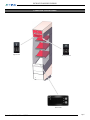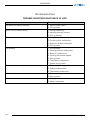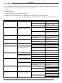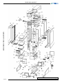
1
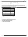
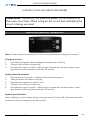
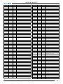
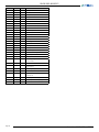
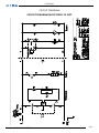
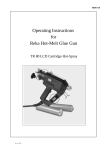
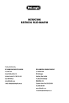
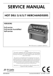
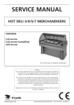
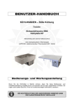
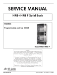
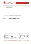
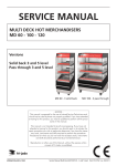
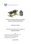
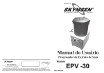
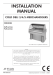
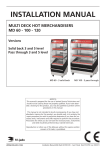
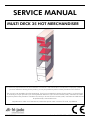
SERVICE MANUAL
MULTI DECK 35 HOT MERCHANDISER
Multi Deck 35 Pret a Manger
- NOTICE This manual is prepared for the use of trained Service Technicians and should not be used by those not properly qualified. If
you have attended a trianing for this product, you may be qualified to perform all the procedures in this manual.
This manual is not intended to be all encompassing. If you have not attended a training for this product, you should read,
in its entirety, the repair procedure you wish to performto determine if you have the necessary tools, instruments and skills
required to perform the procedure. Procedures for which you do not have the necessary tools, instruments and skills should
be performed by a trained technician.
Reproduction or other use of this Manual, without the express written consent of Fri-Jado, is prohibited.
WWW.FRIJADO.COM
Service Manual Multi Deck 35 rev.12/2006
Page 2
Service Manual Multi Deck 35 rev.12/2006
TABLE OF CONTENTS
General technical data .................................................................................................... 4
Technical Data .................................................................................................................................4
Electrical tests and service procedures ............................................................................. 5
Adjusting Danfoss thermostat ............................................................................................................5
Adjusting Danfoss thermostat (continued) ...........................................................................................6
Control locations ..............................................................................................................................7
Troubleshooting .............................................................................................................. 8
Trouble shooting Multi Deck 35 Hot ...................................................................................................8
Exploded views & Partlists ............................................................................................. 10
Circuit Diagram Multi Deck 35 Hot ..................................................................................................13
Circuit Diagrams ........................................................................................................... 13
Service Manual Multi Deck 35 rev.12/2006
Page 3
GENERAL TECHNICAL DATA
GENERAL TECHNICAL DATA
This manual covers the Multi Deck 35 Hot series merchandiser cabinets.
All of the information, illustrations and specifications contained in this manual are based on the
latest product information available at the time of printing.
TECHNICAL DATA
Type
Power (W)
MD 35
Hot
1870
Fuses needed with power connection
230V, 1N ~ 50Hz ( 1 phase with zero )
1x 10 A
Standard plug from factory single pole
13 A
Net weight (kg)
230
Gross weight (kg)
305
Height (mm)
2014
Width (mm)
350
Width with side skirts (mm)
443
Depth (mm)
989
Tools
• Standard set of tools.
• Metric wrenches, sockets and hex socket key wrenches.
• Multi-meter and AC current clamp meter.
• Insulation value tester (Megger)
• Temperature tester.
Page 4
Service Manual Multi Deck 35 rev.12/2006
ELECTRICAL TESTS AND SERVICE PROCEDURES
ELECTRICAL TESTS AND SERVICE PROCEDURES
WARNING: Disconnect the electrical power to the machine at
the main circuit box. Place a tag on the circuit box indicating the
circuit is being serviced.
ADJUSTING DANFOSS THERMOSTAT
Note: In order to adjust the thermostat, first remove the thermostat according prior procedure.
Changing set point
1.
Press both keys together. Set point appears in display and is blinking.
2.
Change value with top or bottom key.
3.
Press both keys again to confirm. When no key is pressed after last confirmation, system
goes back to normal operation mode after 25 seconds.
Setting internal parameters
1.
Press top key for 2 seconds. In display the first parameter appears.
2.
Select parameter with bottom or top key.
3.
Press both keys together to read out value.
4.
Change value with top or bottom key.
5.
Press both keys again to confirm. When no key is pressed after last confirmation, system
goes back to normal operation mode after 25 seconds.
Replacing of thermostat
When installing a new thermostat, always change parameter o7 first to HE. Otherwise some other
parameters cannot be changed to the desired value.
Service Manual Multi Deck 35 rev.12/2006
Page 5
ELECTRICAL TESTS AND SERVICE PROCEDURES
ADJUSTING DANFOSS THERMOSTAT (CONTINUED)
Error message on display
Er: Temperature sensor broken or wiring problem sensor.
Standard value from supplier
°C
90
0
r1
Switching differential
°K
1
2
r2
Maximum setpoint
°C
99
50
r3
Minimum setpoint
°C
0
-60
r4
Off-set temp. sensor
°K
-5
0.0
rE / HE
HE
rE
Description
Setpoint
Parameter
Multi Deck MD 35
Parameters Danfoss thermostat
o7 Function: Cooling/heating
Page 6
Service Manual Multi Deck 35 rev.12/2006
ELECTRICAL TESTS AND SERVICE PROCEDURES
CONTROL LOCATIONS
light switch
heating switch
thermostat
Service Manual Multi Deck 35 rev.12/2006
Page 7
TROUBLESHOOTING
TROUBLESHOOTING
TROUBLE SHOOTING MULTI DECK 35 HOT
Symptom
No power to cabinet controls.
Main fuse or breaker blows.
Illumination does not work.
No heating.
Security thermostat tripped.
No indication on electronic thermostat.
Blower motor does not run.
Page 8
Possible causes
1. Main breaker open.
2. Wiring loose.
1. Wiring incorrectly.
2. Heating element shorted.
3. Wiring shorted.
1. Lamp malfunction.
2. Tumble switch malfunction.
3. Electronic ballast malfuction.
4. Wiring loose.
1. Wiring loose.
2. Heating element malfunction.
3. Relay K1 malfunction.
4. Security thermostat tripped.
5. Wiring loose.
6. Thermostat malfunction.
7. Sensor wiring loose.
1. Blower for heating malfunction.
2. Setting of thermostat.
3. Thermostat malfunction.
1. Electronic thermostat malfunction.
2. Wiring loose.
1. Wiring loose.
2. Motor inoperative.
Service Manual Multi Deck 35 rev.12/2006
TROUBLESHOOTING
This is an analytic description for servicing and repairing all major parts of the Multi Deck 35 Hot. It
consists of 4 basic steps to recognize and solve the problems:
1. Symptoms.
2. Possible causes.
3. Solving of the problem: checking/action.
4. Replacing of parts and testing: a. Replacing is described in this service manual.
b. For testing see control locations on page 17 of this manual.
Description of part
Symptoms
Possible causes
Solving: checking / action
Relay K1
Relay does not come in.
Wiring
Check the wiring
Coil malfunction
Check resistance of coil. This
should be ± 7.0KΩ
Contact burned
Check the contacts
Wiring
Check the wiring
Heating element
Tumble switch
Electronic ballast
PL lamp(s)
Security thermostat
Electronic thermostat
PTC 1000 sensor
The cabinet is not reaching
the adjusted temperature
Check the power on the
element
Element malfunction
Check the current with AC
current tester. See table on
page 15
Light or heating does not
switch on
Wiring
Check the wiring
Contact burned
Check the voltage on “in”and “output”.
Light does not switch on
Wiring
Check the wiring
Ballast malfunction
Replace ballast
Wiring
Check the wiring
Lamp(s) broken
Replace lamp(s)
Wiring
Check the wiring
Security thermostat switched
off
Reset thermostat
Security thermostat malfunction
Replace thermostat
Display does not light up
Wiring
Check the wiring
The cabinet is not reaching
the adjusted temperature or
does not heat up at all
Loose sensor
Check sensor
Thermostat malfunction
Replace thermostat
The cabinet is not reaching
the adjusted temperature or
does not heat up at all
Broken sensor
Replace sensor
Loose sensor
Check wiring
Light does not switch on
The cabinet is not reaching
the adjusted temperature
The cabinet becomes too hot Broken sensor
Blower(s) on heaters
Security thermostat switched
off
Replace sensor
Sensor shorted
Check wiring
Wiring
Check wiring
Check voltage on blower
Blower malfunction
Check for blockage
Replace blower
Blower(s) air curtain
The cabinet is not reaching
the adjusted temperature
Wiring
Check wiring
Check the voltage on blower
Blower malfunction
Check for blockage
Replace blower
Service Manual Multi Deck 35 rev.12/2006
Page 9
EXPLODED VIEWS & PARTLISTS
EXPLODED VIEWS AND PARTLISTS
Page 10
Multi Deck 35 Hot Assembly Drawing
Service Manual Multi Deck 35 rev.12/2006
EXPLODED VIEWS AND PARTLISTS
ITEM
PART NO
QTY
DESCRIPTION
ITEM
PART NO
1
9222118
1
Protection plate dia, transparent
49
9225663
2
9222078
1
Protection plate, illumination inside
50
9222091
2
Castor with brake
3
9181008
2
Switch, tumble
51
9222090
2
Castor without brake
4
9221013
1
Interference filter
59
9224005
6
Shelf support
5
9181071
1
Sticker, light
60
3
Shelf
6
9181072
1
Sticker, heat
60-1
9225630
3
Shelf, top plate, SS
7
9082897
1
Lamp holder
60-1
9225659
3
Shelf, top plate, Ral 3003
8
9222088
1
Lamp, PLL 55 W
60-2
9225631
3
Shelf, bottom plate
9
2007456
1
Starter, S10
61
1
Bottom shelf
10
2007260
1
Ballast, L18, 230V 50Hz
61-1
9225633
1
Bottom shelf, top plate, SS
11
9222119
1
Protection plate, dia, opal
61-1
9225660
1
Bottom shelf, top plate, Ral 1015
11-1
9225667
1
Diastrip
61-2
9225632
1
Bottom shelf, bottom plate
12
9222014
2
Heating element, 1750W 230V
62
9223007
9
Spacing pin, 3D nut M6
13
3500037
1
Thermostat with reset, 100-320 °C
63
9225636
3
Holder, price rail
14
9221011
1
Temperature sensor
64
9222081
1
Productstopper , bottom, perspex
15
9073181
2
Holder, temperature sensor 1/8x4mm
65
9222092
1
Air divider, honeycomb
16
9221000
1
Blower
66
9225635
1
Bracket, honeycomb
17
9221001
1
Blower
67
9223072
3
Price rail, transparent
18
8033659
1
Connecting block, 9-pol.
68
9225634
1
Holder, productstopper
19
3500187
1
Relay, 230V 30A
70
9225616
1
Rear plate
20
9221009
1
Thermostat, Danfoss EKC102A
81
9225646
1
electra panel
22
8031364
1
Grid, blower
82
9070840
1
Grommet
23
3501008
1
Connecting cable with plug UK
13Amps
83
9150195
1
Strain relief PG 13,5
100
9225629
1
Top plate
101
9225623
1
Frame, top plate
102
9225624
1
Bracket
103
9225626
1
Air guiding plate, top
104
9225625
1
Air guiding plate, top rear
105
9225627
1
Air guiding plate
106
9225628
1
Air guiding plate
107
9225615
1
Inner panel
108
9225643
1
Air exit, top
109
9224030
1
Upper cover plate, column
110
9225654
1
Lower cover plate, column
111
9225615
1
Rear panel, inner, SS
111
9225657
1
Rear panel, inner, Ral 1015
112
9220433
1
Frame, right hand side
113
9224065
10
Mounting washer, glass
114
9225614
1
Bended plate, rear
115
9225610
1
Cover plate blower
116
9225609
1
Blower plate
117
9224041
1
Mounting plate blower
118
9225651
2
Lid, (anti air leak)
119
9225606
1
Bottom plate, inner
120
9225607
2
Beam
121
9225605
1
Bottom plate, outer
122
9221018
4
Binding clip, 3,8 - 6,4
123
9225604
1
Cover plate, heating element
124
9225648
1
Clamp plate, brick
125
9225601
2
Frame
126
9225650
3
Prop
23
9091383
1
Connecting cable with Euro plug
24
9222015
1
Protection plate, thermostat
25
9225656
1
Bracket, thermostat
26
9086192
1
Holder, starter
30
9225619
1
Light box
31
9225621
1
Bracket, lampholder
32
9225622
1
Bracket, lamp
33
9225665
1
Top plate
34
9222210
1
Lamp protection, plastic
35
9225618
1
Top plate, bended
36
9225617
1
Panel, lower rear
37
9225644
1
Bottom plate, bended
38
9224097
2
Bracket, temperature probe
39
9222048
8
Rubber gasket
40
9220048
1
Glass panel, left, ass.
41
9220049
1
Glass panel, right, ass.
42
9225641
1
Front plate bottom, SS
42
9225664
1
Front plate bottom, Ral 1015
43
9223028
1
Bumper
44
9171014
2
Plug
45
9172300
2
Spacer
46
9225637
1
Front panel underframe, SS
46
9225661
47
9225639
47
9225662
48
9225638
1
Rear panel underframe
49
9225640
1
Left side panel underframe,SS
Front panel underframe, Ral 1015
1
Right side panel underframe,SS
Right side panel underframe,Ral1015
Service Manual Multi Deck 35 rev.12/2006
QTY
DESCRIPTION
Left side panel underframe, Ral 1015
Page 11
EXPLODED VIEWS AND PARTLISTS
ITEM
PART NO
QTY
DESCRIPTION
127
9225649
1
Clamp plate, brick
128
9225647
1
Bracket, brick
129
9222089
6
Brick, 30x30x4,5 cm
130
9225603
2
Beam, bottom
131
9225645
2
Stabilizer bracket
132
9225642
2
Bracket, front
133
9224019
2
Bracket
134
9225620
1
Base plate illumination
135
9225666
1
Display frame
136
9220462
1
Air column, SS
136
9220435
1
Air column, Ral 1015
137
9224032
1
Partition plate
138
9220434
1
Frame, left
139
9225652
1
Cover plate electra
140
9225653
1
Mounting plate fuse
141
9225670
1
Heat shield bottom.
142
9225669
1
Cover plate service access
143
9225600
1
Bottom plate underframe
1000
4302196
Isolation tape, roll 15mtr, 50x3mm
1000
4302373
Sealant, Dowcorning 732
1000
8072037
Isolation panel PU 865x1333x30
1000
8072098
Name plate Fri-Jado
1000
9004718
Isolation plate type 520,
1000x700x22
1000
9070793
Connection nut, M6x18
1000
9110103
Isolation plate ConlitP756,
1800x900x15
1000
9123148
Label, High temperature
1000
9221010
Cell rubber, roll 25mtr, 15x2mm
1000
9221019
Isolation plate Insulfoam HT034,
122x244x12
1000
9222057
Transport protection strip, lower
1000
9222058
Transport protection strip, upper
Page 12
Service Manual Multi Deck 35 rev.12/2006
Circuit Diagrams
CIRCUIT DIAGRAMS
CIRCUIT DIAGRAM MULTI DECK 35 HOT
Service Manual Multi Deck 35 rev.12/2006
Page 13
Fri-Jado B.V. • P.O. Box 560 • 4870 AN • Etten-Leur • The Netherlands • tel +31 76 50 85 400 • fax +31 76 50 85 444 • [email protected] • www.frijado.com