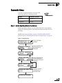
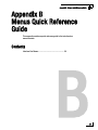
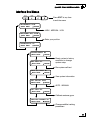
1
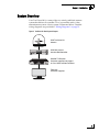
TracVision M1 User’s Guide
(Model M1dx – DISH Network Configuration)
(Model M1-C – ExpressVu Configuration)
®
with Multi-service Interface Box/Controller
Models M1dx / M1-C
TracVision M1
®
TracVision M1 User’s Guide
TracVision M1
Multi-service Interface Box/
Controller Configuration
User’s Guide
This user’s guide provides all of the basic information you need to
operate, set up, and troubleshoot the TracVision M1 satellite TV
antenna system. For detailed installation information, please refer
to the TracVision M1 Installation Guide.
Please direct questions, comments, or suggestions to:
KVH Industries, Inc.
50 Enterprise Center
Middletown, RI 02842-5279 USA
Tel: +1 401 847-3327
Fax: +1 401 849-0045
E-mail: [email protected]
Internet: www.kvh.com
If you have any comments regarding this manual, please e-mail
them to [email protected]. Your input is greatly appreciated!
KVH Part # 54-0580 Rev. B
© 2008-2009, KVH Industries, Inc., All rights reserved.
U.S. Patents Pending
Trademark Information
TracVision, KVH, and the unique light-colored dome with dark contrasting baseplate are
registered trademarks of KVH Industries, Inc.
DVB (Digital Video Broadcasting) is a registered trademark of the DVB Project.
DIRECTV is an official trademark of DIRECTV, Inc.
DISH Network is an official trademark of EchoStar Communications Corporation.
ExpressVu is a property of Bell ExpressVu, a wholly owned subsidiary of Bell Satellite Services.
All other trademarks are the property of their respective owners.
Disclaimer
Every effort has been made to ensure the correctness and completeness of the material in this
document. No company shall be liable for errors contained herein. The information in this
document is subject to change without notice. No warranty of any kind is made with regard to
this material, including, but not limited to, the implied warranties of merchantability and fitness
for a particular purpose.
TracVision M1 User’s Guide
Table of Contents
Table of Contents
1
Introduction
Using this Manual ..............................................................................3
System Overview...............................................................................5
2
Operation
Receiving Satellite TV Signals .........................................................11
Turning the System On/Off ..............................................................12
Understanding the Status Screen....................................................13
Switching Satellites.........................................................................14
Changing the Satellite Switching Mode...........................................16
Product Care ....................................................................................17
3
System Preferences
Adjusting the Display Brightness.....................................................21
Entering Latitude/Longitude ............................................................22
4
Setup
ExpressVu Setup..............................................................................25
DISH Network Setup ........................................................................28
DIRECTV Setup.................................................................................33
Manual Mode Setup.........................................................................35
Resetting the System to Change Setup ...........................................36
i
TracVision M1 User’s Guide
Table of Contents
5
Troubleshooting
Five Simple Checks..........................................................................39
System Status Lights .......................................................................40
Error Messages................................................................................42
Running the Diagnostics Test ..........................................................43
Viewing System Information ............................................................45
Calibrating the Gyros .......................................................................47
Changing Tracking Parameters .......................................................48
Technical Support............................................................................50
A
Wiring Diagrams
Wiring Diagram - 1 Receiver............................................................53
Wiring Diagram - 2 Receivers ..........................................................54
Wiring Diagram - 3 Receivers ..........................................................55
B
Menus Quick Reference Guide
Interface Box Menus ........................................................................59
ii
TracVision M1 User’s Guide
Chapter 1 - Introduction
1. Introduction
This chapter provides a basic overview of this manual and your
TracVision system.
Contents
Using this Manual.............................................................. 3
System Overview............................................................... 5
1
TracVision M1 User’s Guide
Chapter 1 - Introduction
Using this Manual
This manual provides complete operation, setup, and troubleshooting
information for your TracVision system.
Who Should Use This Manual
The user should refer to the “Operation” and “System Preferences”
chapters to learn how to operate the system.
The user, installer, or servicing technician should refer to the “Setup”
chapter for information on configuring the system for the desired
satellite TV service and satellites. The user, installer, or servicing
technician should also refer to the “Wiring Diagrams” appendix for
information on connecting additional receivers.
The user and/or servicing technician/installer should refer to the
“Troubleshooting” chapter to help identify the cause of a system
problem.
Flowchart Conventions
When instructions indicate to select a specific menu option, press the
corresponding interface box button located below the display (see
Figure 1).
Figure 1 Example of Menu Option and Corresponding Interface Box Button
ANTENNA= MANUAL?
CHANGE
ACCEPT
3
TracVision M1 User’s Guide
Chapter 1 - Introduction
Typographical Conventions
This manual uses the following typographical conventions:
Text Example
Description
SELECT SATELLITES
Text as it appears on the interface box
display; also denotes receiver remote
control buttons
See “System Overview” on
page 5.
Cross-reference to another chapter in
the manual or to a website
Types of Notices
This manual uses the following types of notices to call attention to
important or related information:
IMPORTANT!
Be sure to read these carefully to ensure proper operation and
configuration of your TracVision system.
NOTE: Notes contain useful information about system settings.
TIP: Tips contain helpful information, allowing you to get the most out of
your TracVision system.
Related Documentation
In addition to this User’s Guide, the following documents are
provided with your TracVision system:
4
Document
Description
Installation Guide
Complete installation instructions
Product Registration Form
Details on registering the product
Warranty Statement
Warranty terms and conditions
Contents List
List of every part supplied in the kit
TracVision M1 User’s Guide
Chapter 1 - Introduction
System Overview
Your TracVision M1 is a state-of-the-art, actively stabilized antenna
system that delivers live satellite TV to your mobile audio/video
entertainment system. A basic system is illustrated below. Detailed
wiring diagrams are provided in “Wiring Diagrams” on page 51.
Figure 2 TracVision M1 Basic System Diagram
KVH TracVision M1
Antenna
KVH Multi-service
Interface Box/Controller
HDTV SATELLITE RECEIVER
SATELLITE
CANCEL
OFF-AIR
6100
POWER
SYSTEM INFO
Satellite TV Receiver
Customer-supplied; see page 6
for list of KVH-validated receivers
Television
Customer-supplied
5
TracVision M1 User’s Guide
Chapter 1 - Introduction
System Components
The TracVision M1 system includes the following components:
The antenna uses integrated DVB technology to
quickly acquire and track the correct satellite,
switch between satellites, and send TV signals to
the interface box. Internal gyros allow the
antenna to track the satellite at all times, even
while you’re on the move!
The multi-service interface box/controller
supplies power to the antenna and delivers
satellite TV signals to your satellite TV
receiver. The interface box also allows you
to set up the system using the pushbuttons
and LCD display.
NOTE: Henceforward, this manual uses the term “interface box” to refer to
the multi-service interface box/controller.
Compatible Receivers
To ensure compatibility with the TracVision system, KVH
recommends the receiver models shown in the table below. These
receivers have all been validated by KVH to work well with the
TracVision system. For information on connecting different receiver models,
contact KVH Technical Support at 401-847-3327.
Figure 3 KVH-Validated Receivers
Standard-Definition Models
DIRECTV
DISH Network
ExpressVu
D12
D11
D10
311
211k
211
3100
4110
High-Definition (HD) Models
6
DIRECTV
DISH Network
ExpressVu
HD not
supported
211k
211
6100
6131
TracVision M1 User’s Guide
Chapter 1 - Introduction
ExpressVu Configuration
Other than a satellite TV receiver, no additional
components are needed to receive both highdefinition (HD) and standard-definition
programming from ExpressVu’s 91 and 82
satellites. The antenna will automatically switch between these
satellites as necessary as you change channels using the primary
receiver’s remote.
DISH Network Configuration
Other than a satellite TV receiver, no additional
components are necessary to receive both highdefinition (HD) and standard-definition
N E T W O R K
programming from three DISH Network satellites:
119, 110, and either 61 or 129 (choose the third satellite for your
particular region - see “DISH Network Setup” on page 28). The
antenna will automatically switch between these three satellites as
necessary as you change channels using the primary receiver’s remote.
DIRECTV Configuration
You can receive DIRECTV programming from the
101 and 119 satellites without any special
equipment. All you need is a DIRECTV receiver. The
antenna will automatically switch between these
two satellites as necessary as you change channels
using the primary receiver’s remote.
7
TracVision M1 User’s Guide
Chapter 2 - Operation
2. Operation
This chapter explains everything you need to know to operate the
TracVision system.
Contents
Receiving Satellite TV Signals ......................................... 11
Turning the System On/Off .............................................. 12
Understanding the Status Screen.................................... 13
Switching Satellites......................................................... 14
Changing the Satellite Switching Mode........................... 16
Product Care.................................................................... 17
9
TracVision M1 User’s Guide
Chapter 2 - Operation
Receiving Satellite TV Signals
Television satellites are located in fixed positions above the Earth’s
equator and beam TV signals down to certain regions of the planet
(not worldwide). To receive TV signals from a satellite, you must be
located within that satellite’s unique coverage area.
TIP: For your convenience, KVH provides links to several websites that offer
satellite coverage information. Simply visit our website at www.kvh.com/
footprint.
Figure 4 Example of a Satellite Location and Coverage Area
Equator
In addition, since TV satellites are located above the equator, the
TracVision antenna must have a clear view of the sky to receive
satellite TV signals. Anything that stands between the antenna and the
satellite can block the signal, resulting in lost reception. Common
causes of blockage include trees, buildings, bridges, and onboard
equipment. Heavy rain, ice, or snow might also temporarily interrupt
satellite signals.
Figure 5 Example of Satellite Blockage
Blocked!
Tra
racVision
11
TracVision M1 User’s Guide
Chapter 2 - Operation
Turning the System On/Off
Since the interface box supplies power to the antenna, you can turn the
antenna on or off using the interface box Power switch.
Turning On the System
Follow the steps below to turn on your TracVision system.
1. Make sure the antenna has a clear view of the sky.
2. Turn on your satellite TV receiver and TV.
3. Press the Power switch on the front of the TracVision
interface box.
Figure 6 Interface Box Components
Display
Power
Switch
Status
Lights
Buttons
4. Wait one minute for system startup.
Once the antenna finds the correct satellite, all three status
lights on the interface box should be lit green. If any lights are
not lit green, see “System Status Lights” on page 40.
Turning Off the System
Follow the steps below to turn off your TracVision system.
1. Press the Power switch on the front of the TracVision
interface box.
2. Turn off your satellite TV receiver and TV.
12
TracVision M1 User’s Guide
Chapter 2 - Operation
Understanding the Status Screen
Following startup, the interface box displays the current system status.
Figure 7 Interface Box Status Screen
Antenna
State
Service
Satellite
TRACKING EXVU 91
DUAL-SAT MODE
Signal
Strength
Operating
Mode
Screen Field
Description
Antenna State
Current state of the antenna:
• Idle
• Initializing
• Searching
• Tracking
• Error
Service
Satellite TV service currently set up in the
TracVision system:
• DTV (DIRECTV)
• DISH (DISH Network)
• EXVU (ExpressVu)
• MAN (Manual)
Satellite
Satellite that the antenna is currently tracking
This number refers to the satellite’s “orbital slot,”
which is its longitudinal location above the equator.
Signal Strength
Strength of the satellite TV signal, as measured
by RF level
The more bars, the stronger the signal, just like a
cell phone. Three bars = good reception.
Operating Mode
Mode of operation currently set up in the
TracVision system:
• Dual-Sat (DIRECTV or ExpressVu)
• Single-Sat (ExpressVu)
• DISH 1000/129 (DISH Network)
• DISH 1000/61 (DISH Network)
• DISH 500 (DISH Network)
For a list of satellites tracked in each operating
mode, see “Setup” on page 23.
13
TracVision M1 User’s Guide
Chapter 2 - Operation
Switching Satellites
If your system is set up to track multiple satellites, you can easily
switch between them. Use the switching method that applies to your
particular setup. You can identify the current satellite switching
method by the format of the status screen:
Status Screen Examples
TRACKING DISH 119
DISH 1000/129 MODE
Satellite Switching Method
Automatic
TRACKING EXVU 91
DUAL-SAT MODE
TRACKING DISH 119
PUSH
TO SWITCH SAT
TRACKING EXVU 91
PUSH
TO SWITCH SAT
14
Manual
TracVision M1 User’s Guide
Chapter 2 - Operation
Automatic Switching
All operating modes provide automatic satellite switching using the
primary receiver (the receiver connected to the “Unstacked Output”
jack on the interface box). The antenna will automatically switch
satellites as you change channels using the primary receiver’s remote.
NOTE: The receiver might take up to 30 seconds to display video when
changing channels, switching between satellites, and/or switching between
standard-definition and high-definition channels.
NOTE: DISH Network receivers may switch to a different satellite on their
own in response to a blockage condition. For example, if the antenna’s view of
the 110 satellite becomes blocked for over a minute, the receiver may try
switching to the 119 satellite. If this occurs, you will see an error message on
the TV. Once the antenna can see the selected satellite again, the receiver will
automatically switch back and the error message will disappear.
How Switching Satellites Affects Additional Receivers
The TracVision system tracks one satellite at a time. Therefore, if you
switch satellites using the primary receiver, televisions connected to
other receivers might display different programming, no
programming, or an error message. Simply select a channel carried by
the new satellite, or use the primary receiver to switch back to the
original satellite. Only the primary receiver controls satellite selection.
Manual Switching
If you set up the system to track a custom set of satellites in Manual
mode, you can use the interface box to switch among them. Simply
press the CHANGE button until the display shows the desired
satellite. Then press ACCEPT.
15
TracVision M1 User’s Guide
Chapter 2 - Operation
Changing the Satellite Switching Mode
Unless your system is set up in Manual mode, the antenna will
automatically switch satellites as you change channels using the
receiver’s remote control. However, if you want to manually select a
satellite for some reason, the interface box allows you to switch from
automatic to manual switching. (You can also switch back to
automatic switching using this same menu function.)
Follow the steps in the flowchart below to change the satellite
switching mode.
Figure 8 Satellite Switching Mode
Press MENUS until
DIAGNOSTICS= No is displayed.
DIAGNOSTICS= NO
NEXT MENU
CHANGE
DIAGNOSTICS= YES?
CHANGE
ACCEPT
ENTERING DIAGNOSTICS
SYSTEM RESET= NO
NEXT MENU
CHANGE
SAT SWITCH= AUTO
NEXT MENU
CHANGE
SAT SWITCH= MANUAL?
CHANGE
ACCEPT
SAT SWITCH= MANUAL
16
Press MENUS until
SAT SWITCH= AUTO
is displayed.
TracVision M1 User’s Guide
Chapter 2 - Operation
Product Care
Please consider the following antenna care guidelines for maintaining
peak performance:
•
Periodically wash the exterior of the antenna dome with fresh
water and mild detergent. Avoid harsh cleansers and volatile
solvents (such as acetone) and do not spray the dome directly with
high-pressure water.
•
If you wish to paint the dome, use only non-metallic automotive
paint without a primer coat. Any paint that contains metal will
block satellite signals and impair reception.
17
TracVision M1 User’s Guide
Chapter 3 - System Preferences
3. System Preferences
This chapter explains how to change the brightness and latitude/
longitude settings.
Contents
Adjusting the Display Brightness..................................... 21
Entering Latitude/Longitude ............................................ 22
19
TracVision M1 User’s Guide
Chapter 3 - System Preferences
Adjusting the Display Brightness
Follow the steps in the flowchart below if you need to adjust the
brightness of the interface box display.
Figure 9 Brightness Setting
Press MENUS until
BRIGHTNESS is displayed.
BRIGHTNESS= HIGH
NEXT MENU
CHANGE
Press CHANGE until
the desired setting is
displayed: HIGH,
MEDIUM, or LOW.
BRIGHTNESS= MEDIUM?
CHANGE
ACCEPT
BRIGHTNESS= MEDIUM
Press EXIT to exit the menu.
21
TracVision M1 User’s Guide
Chapter 3 - System Preferences
Entering Latitude/Longitude
Follow the steps in the flowchart below to enter your vessel’s latitude
and longitude into the system. The antenna will use your position
information to speed up satellite acquisition. (If the antenna knows
where you are located, it knows where it should start looking for the
satellite.)
Figure 10 Latitude/Longitude Setting
Press MENUS until
LAT/LONG is displayed.
LAT/LONG= 41N, 071W
NEXT MENU
CHANGE
LAT/LONG= 41N, 071W?
CHANGE
ACCEPT
LAT/LONG= 41N, 071W
CHANGE
ACCEPT
LAT/LONG= 55N, 012E?
CHANGE
ACCEPT
RESTARTING ANTENNA
22
Press CHANGE to set each
digit plus N/S (north or south)
and E/W (east or west). Press
ACCEPT to save each digit.
TracVision M1 User’s Guide
Chapter 4 - Setup
4. Setup
When you turn on the TracVision system for the first time, the interface
box display shows “SYSTEM NEEDS SETUP.” This chapter explains how
to set up the system for your desired satellite TV service.
Contents
ExpressVu Setup.............................................................. 25
DISH Network Setup ........................................................ 28
DIRECTV Setup................................................................. 33
Manual Mode Setup......................................................... 35
Resetting the System to Change Setup ........................... 36
23
TracVision M1 User’s Guide
Chapter 4 - Setup
ExpressVu Setup
You can set up the system for any one of the
following ExpressVu operating modes:
Mode
Satellites Tracked
Dual-Sat
91 and 82
Single-Sat
91 only
Step 1 - Set the Operating Mode in the Antenna
Follow the steps in Figure 11 to set up the antenna for your selected
ExpressVu operating mode. Then keep the antenna turned on for the
next step.
NOTE: If the status screen does not show “SYSTEM NEEDS SETUP,”
follow the steps in “Resetting the System to Change Setup” on page 36.
Figure 11 ExpressVu Setup
TRACKING DTV 101
SYSTEM NEEDS SETUP
Press any button
to begin.
SERVICE= DIRECTV?
CHANGE
ACCEPT
Press CHANGE until
EXPRESSVU is
displayed.
SERVICE= EXPRESSVU?
CHANGE
ACCEPT
MODE= DUAL-SAT?
CHANGE
ACCEPT
Press CHANGE until
the desired mode is
displayed. Then press
ACCEPT.
MODE= SINGLE-SAT?
CHANGE
ACCEPT
INSTALLING EXVU SATS
XX XX
Displays satellites
installed for the
selected mode.
RESTARTING ANTENNA
25
TracVision M1 User’s Guide
Chapter 4 - Setup
Step 2 - Run Receiver Check Switch Tests
To configure the primary receiver for your selected ExpressVu mode
and automatic satellite switching, you need to run two Check Switch
tests on the receiver. The first Check Switch test finds the correct
satellites; the second configures the receiver for those satellites. To
configure additional receivers for your selected mode, you need to
run just one Check Switch test on each (see page 27).
IMPORTANT!
If you remove a receiver from the vessel and configure it for a
home setup, you will need to repeat this step to reconfigure that
receiver for a mobile setup whenever you reconnect it to the
TracVision system.
Primary Receiver - Run Two Check Switch Tests
Follow these steps to run two Check Switch tests on the primary
receiver, which is connected to the “Unstacked Output” jack on the
interface box. This receiver controls satellite selection.
1. Make sure the vessel is docked in calm water, and
ensure the antenna has an unobstructed view of the sky
so it can “see” all of the desired satellites.
2. Apply power to the TV and receiver. (If the antenna is
turned off, turn it back on using the interface box power
switch and wait for system startup, until the interface
box shows “TRACKING.”)
3. Using the receiver’s remote, go to the “Point Dish/
Signal Strength” screen (press MENU, 6, 1, 1).
4. Choose Check Switch, then press SELECT.
5. Choose Check, then press SELECT.
6. Wait at least 15 minutes, or until the interface box
shows “PLEASE RUN ANOTHER CHECK SWITCH,”
before proceeding to allow the antenna to find all of the
satellites. Disregard any messages that appear on the
TV screen; they do not correctly indicate when the
antenna is ready for the next Check Switch test.
7. Once you have waited the appropriate amount of time,
choose Retest, then press SELECT to run a second
Check Switch test.
26
TracVision M1 User’s Guide
Chapter 4 - Setup
8. Once the Check Switch test is complete, refer to the
table in Figure 12 and verify the values displayed on
your TV match those required for your selected service.
If your values match: Exit the menu and allow the receiver to
download the program guide.
If your values do not match, and you selected Single-Sat
mode: It is normal for your TV to show “No Switch Detected,”
“Switch Type Unknown,” or a similar error message. No action
is required.
If your values do not match, and you selected Dual-Sat mode:
Reset the system (follow the process on page 36), then repeat
the entire ExpressVu setup process, starting with Step 1 on
page 25.
Figure 12 Expected Check Switch Results
ExpressVu Dual-Sat Results
Input
1
1
2
2
Satellite
91
91
82
82
Polarity
Odd
Even
Odd
Even
Status
Reception Verified
Switch
SW21
Additional Receiver(s) - Run One Check Switch Test
If any receivers are connected to the “Stacked Output” jack on the
interface box, follow these steps to run a single Check Switch test on
each additional receiver, one at a time.
1. Temporarily disconnect the primary receiver from the
“Unstacked Output” jack on the interface box. Connect
the additional receiver in its place.
2. Perform Steps 1-5 on page 26 to run the test.
3. Wait 15 minutes, then verify that the values displayed
on the TV match those shown in Figure 12. If the values
do not match, and the system is set to Dual-Sat mode,
try running another Check Switch test. If your system is
set to Single-Sat mode, an error message will appear
instead; this is normal.
27
TracVision M1 User’s Guide
Chapter 4 - Setup
DISH Network Setup
You can set up the system for any one of the
following DISH Network operating modes:
Mode
Satellites Tracked
DISH 1000/129
119, 110, and 129
DISH 1000/61
119, 110, and 61
DISH 500
119 and 110
N E T W O R K
Whichever mode you choose, the antenna will automatically switch
between satellites as necessary as you change channels using your
primary receiver’s remote control.
DISH 1000/129 or DISH 1000/61
To ensure you receive the best satellite reception, use the map in
Figure 13 to help determine the appropriate DISH 1000 mode for your
geographic area. Check with DISH Network for local channels
availability.
Figure 13 Approximate Areas Recommended for DISH 1000 Modes
= DISH 129 Satellite Recommended
= DISH 61 Satellite Recommended
DISH 500
Select this mode if you wish to receive programming from just the 119
and 110 satellites for DISH 500 service.
Setup Process
Once you have chosen an operating mode, perform the steps on the
following pages to set up the system for DISH Network service:
1. Set the operating mode in the antenna
2. Run receiver Check Switch tests
28
TracVision M1 User’s Guide
Chapter 4 - Setup
Step 1 - Set the Operating Mode in the Antenna
Follow the steps in Figure 14 to set up the antenna for your selected
DISH Network operating mode. Then keep the antenna turned on for
the next step.
NOTE: If the status screen does not show “SYSTEM NEEDS SETUP,”
follow the steps in “Resetting the System to Change Setup” on page 36.
Figure 14 DISH Network Setup
TRACKING DTV 101
SYSTEM NEEDS SETUP
Press any button
to begin.
SERVICE= DIRECTV?
CHANGE
ACCEPT
SERVICE= DISH?
CHANGE
ACCEPT
MODE= DISH 1000/129?
CHANGE
ACCEPT
Press CHANGE until
desired mode displays;
then press ACCEPT.
MODE= DISH 1000/61?
CHANGE
ACCEPT
MODE= DISH 500?
CHANGE
ACCEPT
INSTALLING DISH SATS
Displays satellites
installed for the
selected mode.
RESTARTING ANTENNA
29
TracVision M1 User’s Guide
Chapter 4 - Setup
Step 2 - Run Receiver Check Switch Tests
IMPORTANT!
If your primary receiver was preconfigured by KVH for your
desired DISH Network satellites, you only need to run one Check
Switch test to set up the system, not two as described below.
To configure the primary receiver for your selected DISH Network
mode and automatic satellite switching, you need to run two Check
Switch tests on the receiver. The first Check Switch test finds the
correct satellites; the second configures the receiver for those satellites.
To configure additional receivers for your selected mode, you need to
run just one Check Switch test on each (see page 32).
IMPORTANT!
If you remove a receiver from the vessel and configure it for a
home setup, you will need to repeat this step to reconfigure that
receiver for a mobile setup whenever you reconnect it to the
TracVision system.
Primary Receiver - Run Two Check Switch Tests
Follow these steps to run two Check Switch tests on the primary
receiver, which is connected to the “Unstacked Output” jack on the
interface box. This receiver controls satellite selection.
1. Make sure the vessel is docked in calm water, and
ensure the antenna has an unobstructed view of the sky
so it can “see” all of the desired satellites.
2. Apply power to the TV and receiver. (If the antenna is
turned off, turn it back on using the interface box power
switch and wait for system startup, until the interface
box shows “TRACKING.”)
3. Using the receiver’s remote, go to the “Point Dish/
Signal Strength” screen (press MENU, 6, 1, 1).
4. Choose Check Switch, then press SELECT.
5. Choose Test, then press SELECT.
6. Wait at least 15 minutes, or until the interface box
shows “PLEASE RUN ANOTHER CHECK SWITCH,”
before proceeding to allow the antenna to find all of the
satellites. Disregard any messages that appear on the
TV screen; they do not correctly indicate when the
antenna is ready for the next Check Switch test.
7. Once you have waited the appropriate amount of time,
select Test again to run a second Check Switch test.
30
TracVision M1 User’s Guide
Chapter 4 - Setup
8. Once the Check Switch test is complete, refer to the
tables in Figure 15 and verify the values displayed on
your TV match those required for your selected service.
If your values match: Exit the menu and allow the receiver to
download the program guide.
If your values do not match: Reset the system (follow the
process on page 36), then repeat the entire DISH setup process,
starting with Step 1 on page 29.
Figure 15 Expected Check Switch Results
DISH 1000/129 Results
Port
1
2
3
Satellite
119
110
129
Trans
OK
OK
OK
Status
Reception Verified
Switch
SW64
DISH 1000/61 Results
Port
1
2
3
Satellite
119
110
61
Trans
OK
OK
OK
Status
Reception Verified
Switch
SW64
DISH 500 Results
Input
1
1
2
2
Satellite
119
119
110
110
Polarity
Odd
Even
Odd
Even
Status
Reception Verified
Switch
SW42
31
TracVision M1 User’s Guide
Chapter 4 - Setup
Additional Receiver(s) - Run One Check Switch Test
IMPORTANT!
You do not need to run a Check Switch test on an additional
receiver if it was preconfigured by KVH for your desired DISH
Network satellites.
If any receivers are connected to the “Stacked Output” jack on the
interface box, follow these steps to run a single Check Switch test on
each additional receiver, one at a time.
1. Temporarily disconnect the primary receiver from the
“Unstacked Output” jack on the interface box. Connect
the additional receiver in its place.
2. Perform Steps 1-5 on page 30 to run the test.
3. Wait 15 minutes, then verify that the values displayed
on the TV match those shown in Figure 15. If the values
do not match, try running another Check Switch test.
32
TracVision M1 User’s Guide
Chapter 4 - Setup
DIRECTV Setup
You can set up the system for any one of the
following DIRECTV operating modes:
Mode
Satellites Tracked
Tri-Sat Auto
Not used
Tri-Sat Pairs
Dual-Sat
101 and 119
Tri-Sat Auto or Tri-Sat Pairs – Not Used
These modes are no longer used. The Tri-Sat Auto mode supported the
Tri-Sat AutoSwitch; the Tri-Sat Pairs mode supported the HDTV
Converter. Neither of these devices is available today.
Dual-Sat
Select this mode to receive programming from the 101 and 119
satellites for DIRECTV service. Follow the steps in Figure 16 on
page 34 to set up the antenna.
NOTE: If the status screen does not show “SYSTEM NEEDS SETUP,”
follow the steps in “Resetting the System to Change Setup” on page 36.
33
TracVision M1 User’s Guide
Chapter 4 - Setup
Figure 16 DIRECTV Setup
TRACKING DTV 101
SYSTEM NEEDS SETUP
Press any button
to begin.
SERVICE= DIRECTV?
CHANGE
ACCEPT
MODE= TRI-SAT AUTO?
CHANGE
ACCEPT
MODE= TRI-SAT PAIRS?
CHANGE
ACCEPT
MODE= DUAL-SAT?
CHANGE
ACCEPT
INSTALLING DTV SATS
101 119
RESTARTING ANTENNA
34
Press CHANGE until
DUAL-SAT is displayed.
TracVision M1 User’s Guide
Chapter 4 - Setup
Manual Mode Setup
If none of the automatic modes described earlier include all of the
satellites you wish to track, you can set up the system in Manual mode
to track up to five satellites of your choice. You will then be able to
switch between these satellites using the buttons on the interface box.
Follow the steps in Figure 17 to set up the antenna in Manual mode.
NOTE: If the status screen does not show “SYSTEM NEEDS SETUP,”
follow the steps in “Resetting the System to Change Setup” on page 36.
Figure 17 Manual Mode Setup
TRACKING DTV 101
SYSTEM NEEDS SETUP
Press any button
to begin.
SERVICE= DIRECTV?
CHANGE
ACCEPT
Press CHANGE until
SERVICE= MANUAL
is displayed.
SERVICE= MANUAL?
CHANGE
ACCEPT
SAT 1 OF 5= 101?
CHANGE
ACCEPT
SAT 2 OF 5= NONE?
CHANGE
ACCEPT
Press CHANGE until
the display shows the
desired satellite: 61,
72, 82, 91, 101, 110,
119, 129, 148 or
NONE. Then press
ACCEPT.
Repeat this procedure for satellites
3-5. Then press ACCEPT.
INSTALLING SATS
XXX XXX XXX XXX XXX
RESTARTING ANTENNA
35
TracVision M1 User’s Guide
Chapter 4 - Setup
Resetting the System to Change Setup
If you need to change the antenna’s setup to receive a different satellite
TV service and/or track a different satellite, follow the steps in
Figure 18 to reset the system. Once the system has reset to its factory
conditions, you will be able to set up the system as described earlier in
this section.
IMPORTANT!
(DISH/ExpressVu only) You will need to reconfigure all of the
receivers after you select a different operating mode. Refer to
page 26 (ExpressVu) or page 30 (DISH) for details.
Figure 18 Factory Reset
Press MENUS until
DIAGNOSTICS= No is displayed.
DIAGNOSTICS= NO
NEXT MENU
CHANGE
DIAGNOSTICS= YES?
CHANGE
ACCEPT
ENTERING DIAGNOSTICS
SYSTEM RESET= NO
NEXT MENU
CHANGE
SYSTEM RESET= YES?
CHANGE
ACCEPT
RESET TO FACTORY?
ACCEPT
EXIT
SYSTEM RESET
TRACKING DTV 101
SYSTEM NEEDS SETUP
36
TracVision M1 User’s Guide
Chapter 5 - Troubleshooting
5. Troubleshooting
This chapter identifies potential problems along with their possible
causes and solutions. It also explains how to get technical support.
Contents
Five Simple Checks ......................................................... 39
System Status Lights....................................................... 40
Error Messages ............................................................... 42
Running the Diagnostics Test.......................................... 43
Viewing System Information............................................ 45
Calibrating the Gyros ....................................................... 47
Changing Tracking Parameters ....................................... 48
Technical Support............................................................ 50
37
TracVision M1 User’s Guide
Chapter 5 - Troubleshooting
Five Simple Checks
If you are experiencing a problem receiving satellite TV with your
TracVision system, perform the five simple checks below. If none of
these are the problem, check the status lights on the interface box and/
or perform a diagnostics test, as explained in “System Status Lights”
on page 40 and “Running the Diagnostics Test” on page 43.
TIP: You can also try resetting the satellite TV receiver. Turn off and unplug
the receiver, wait one minute, then plug it back in and turn it back on.
Can the antenna see the satellite?
The antenna requires an unobstructed view of the sky to receive
satellite TV signals. Common causes of blockage include trees,
buildings, bridges, mountains, and onboard equipment.
Is there excessive dirt or moisture on the antenna dome?
Dirt buildup or moisture on the dome can reduce satellite reception.
Clean the exterior of the dome periodically.
Is it raining heavily?
Heavy rain or snow can weaken satellite TV signals. Reception should
improve once the inclement weather subsides.
Is the receiver configured for your selected mode? (ExpressVu/DISH Only)
All ExpressVu and DISH Network receivers that you connect to the
TracVision system need to be configured for the antenna’s operating
mode. To configure a receiver, you need to run its Check Switch test.
Refer to the step-by-step instructions on page 26 (ExpressVu) or
page 30 (DISH).
Is everything turned on and connected properly?
Make sure the power switch on the front of the interface box is turned
on (the VOLTAGE light on the front of the interface box should be lit
green). Also, make sure your TV and receiver are both turned on and
set up for the satellite input. Finally, check the cables connecting all of
these components to ensure none have come loose.
39
TracVision M1 User’s Guide
Chapter 5 - Troubleshooting
System Status Lights
Three status lights on the front of the interface box indicate the current
status of the system and can help you identify problems (see
Figure 19).
Figure 19 System Status Lights
Status Lights
During normal operation, all three status lights should be lit green.
The following tables explain what the different light conditions
indicate.
VOLTAGE Light
The table below explains what the VOLTAGE light indicates.
40
Light is...
Indicates
Description
Off
Off
Interface box is off (power switch is
off) or no power input
Green
OK
Good power (10-16 VDC at interface
box)
Green,
flashing
Cable Open
Open detected in antenna cable
(check the antenna coax connection)
Orange
Low Power
Low power (9-10 VDC) at interface
box)
Red,
flashing
Bad Power
Insufficient power (less than 9 VDC
or more than 16 VDC input)
TracVision M1 User’s Guide
Chapter 5 - Troubleshooting
RECEIVER Light
The table below explains what the RECEIVER light indicates.
Light is...
Indicates
Description
Green
OK
Good communications with receiver
Orange
No comm
No communications with receiver;
receiver is off or disconnected
Orange,
flashing
Overload
Overload or short circuit detected
on the antenna cable
Red
Fault
Power fault detected in interface box
ANTENNA Light
The table below explains what the ANTENNA light indicates.
Light is...
Indicates
Description
Off
Off
Antenna is off, disconnected, or has
insufficient power
Green
Tracking
Antenna is tracking the selected
satellite
Green,
flashing
Searching
Antenna is searching for a satellite
Orange,
flashing
Overload
Overload or short circuit detected
on the antenna cable
Red
No comm
No communications with antenna
Red,
flashing
Fault
Error detected in antenna
41
TracVision M1 User’s Guide
Chapter 5 - Troubleshooting
Error Messages
The table below lists possible error messages and the appropriate
corrective action.
Warning
SYSTEM SAT MISMATCH
PRESS
TO FIX
SAT NOT INSTALLED
TRACKING DTV 101
SYSTEM NEEDS SETUP
42
Description
The interface box and antenna
are out of sync. Just press
ACCEPT to synchronize.
The receiver is tuned to a
channel carried by a satellite that
is not installed in the antenna.
You might need to change your
setup.
This is not a true error message.
This screen indicates that the
system needs to be configured
for the desired satellite service/
configuration. Refer to “Setup”
on page 23 for detailed setup
information.
TracVision M1 User’s Guide
Chapter 5 - Troubleshooting
Running the Diagnostics Test
In addition to the front panel status lights, the interface box includes a
self-test function within its Diagnostics menu. Follow the steps in
Figure 20 to perform a diagnostic test. For information on diagnostic
test results, see “Diagnostic Test Results” on page 44.
Figure 20 Diagnostics Test
Press MENUS until
DIAGNOSTICS= No is displayed.
DIAGNOSTICS= NO
NEXT MENU
CHANGE
DIAGNOSTICS= YES?
CHANGE
ACCEPT
ENTERING DIAGNOSTICS
SYSTEM RESET= NO
NEXT MENU
CHANGE
RUN TEST= NO
NEXT MENU
CHANGE
RUN TEST= YES?
CHANGE
ACCEPT
RUNNING TEST
Once the test is complete, the
display shows the antenna status.
ANTENNA: TRACKING
PRESS
TO CONTINUE
Press MENUS to scroll
through the remaining
status messages.
43
TracVision M1 User’s Guide
Chapter 5 - Troubleshooting
Diagnostic Test Results
The table below lists all of the status messages.
Status Message
ANTENNA: TRACKING
PRESS
TO CONTINUE
SATELLITE: 91
PRESS
TO CONTINUE
BIT ERROR: OK,928
PRESS
TO CONTINUE
AGC LEVEL: OK,22500
PRESS
TO CONTINUE
SAT 1: 91
PRESS
TO CONTINUE
LAT/LONG: 41N, 071W
PRESS
TO CONTINUE
CABLE STATE: OK
PRESS
TO CONTINUE
SYSTEM DC: OK,12.3
PRESS
TO CONTINUE
ANTENNA DC: OK,41.0
PRESS
TO CONTINUE
44
Description
Antenna status: Idle, Initializing,
Searching, Tracking, or Error
Name of the currently selected
satellite
Bit error rate:
OK: Less than 2001
High: Between 2001-8000
Bad: Greater than 8000
Automatic gain control level:
OK: Between 20000-25000
Bad: Less than 20000 or greater
than 25000
List of installed satellites. Press
MENUS to scroll through the list
Last latitude/longitude that you
entered into the antenna
Antenna cable status:
OK, Open, or Shorted
Input voltage (DC power):
OK: 10-16 VDC
Low: 9-10 VDC
Bad: Less than 9 VDC or more
than 16 VDC
Antenna voltage (DC power):
OK: 39-42 VDC
Low: 37-39 VDC
Bad: Less than 37 VDC
TracVision M1 User’s Guide
Chapter 5 - Troubleshooting
Viewing System Information
You can view the TracVision system’s software versions and serial
numbers on the interface box display. Follow the steps in Figure 21 to
display the system information. For more information on system
information results, see “System Information Results” on page 46.
Figure 21 System Information
Press MENUS until
DIAGNOSTICS= No is displayed.
DIAGNOSTICS= NO
NEXT MENU
CHANGE
DIAGNOSTICS= YES?
CHANGE
ACCEPT
ENTERING DIAGNOSTICS
SYSTEM RESET= NO
NEXT MENU
CHANGE
Press MENUS until
SHOW SYS INFO=NO
is displayed.
SHOW SYS INFO= NO
NEXT MENU
CHANGE
SHOW SYS INFO= YES?
CHANGE
ACCEPT
KVH INDUSTRIES
PRESS
TO CONTINUE
Press MENUS to scroll
through the system
information screens.
45
TracVision M1 User’s Guide
Chapter 5 - Troubleshooting
System Information Results
The table below lists all of the status information messages.
Information Message
TRACVISION M1
PRESS
TO CONTINUE
SYS SW: 1.2
PRESS
TO CONTINUE
RF SW: 1.3
PRESS
TO CONTINUE
MOTOR SW: 1.4
PRESS
TO CONTINUE
JBOX SW: 1.5
PRESS
TO CONTINUE
ANT.SER.# 081201234
PRESS
TO CONTINUE
JBOX SER.# 081205678
PRESS
TO CONTINUE
Description
Model of TracVision Antenna
Version of antenna main
software
Version of antenna RF software
Version of antenna motor
controller software
Version of interface box
software
Serial number of antenna
Serial number of interface box
NOTE: The first 4 digits of the serial number indicate the year and month
(YYMM) the product was manufactured. For example, if the antenna has a
serial number of 081201234, it was built in December 2008.
46
TracVision M1 User’s Guide
Chapter 5 - Troubleshooting
Calibrating the Gyros
The TracVision antenna’s gyros continuously measure the motion of
your vessel and send this data to the antenna’s motor control circuitry
to keep the antenna pointed at the satellite. At the factory, each
antenna gyro is precisely calibrated to work with the antenna’s circuit
board. Therefore, if you ever replace a gyro or circuit board in your
antenna, follow the steps in Figure 22 to recalibrate the gyros for the
new part.
IMPORTANT!
Calibrate the gyros only if directed by KVH Technical Support, and
only while the vessel is stationary in calm water. A poor gyro
calibration can reduce the performance of the antenna.
Figure 22 Gyro Calibration
Press MENUS until
DIAGNOSTICS= NO is displayed.
DIAGNOSTICS= NO
NEXT MENU
CHANGE
DIAGNOSTICS= YES?
CHANGE
ACCEPT
ENTERING DIAGNOSTICS
SYSTEM RESET= NO
NEXT MENU
CHANGE
CAL GYRO= NO
NEXT MENU
Press NEXT MENU
until CAL GYRO= NO
is displayed.
CHANGE
CAL GYRO= YES?
CHANGE
ACCEPT
CALIBRATING GYRO
AZ:
EL:
CALIBRATING GYRO
AZ: PASS
EL: PASS
Verify that azimuth (AZ)
and elevation (EL) gyros
both pass.
47
TracVision M1 User’s Guide
Chapter 5 - Troubleshooting
Changing Tracking Parameters
On rare occasions, a satellite service provider may change the
configuration of one of its satellites. Since your TracVision antenna
identifies a satellite based on the configuration data it has stored in
memory, the antenna will no longer be able to track the satellite if its
configuration changes. For this reason, the interface box allows you to
change any satellite parameter stored in the antenna’s memory.
IMPORTANT!
Change tracking parameters only if directed by KVH Technical
Support. An incorrect tracking parameter can significantly reduce
the performance of the antenna.
Follow the steps in Figure 23 on the next page to change a tracking
parameter for an installed satellite.
48
TracVision M1 User’s Guide
Chapter 5 - Troubleshooting
Figure 23 Tracking Parameter Changes
Press MENUS until
DIAGNOSTICS= NO is displayed.
DIAGNOSTICS= NO
NEXT MENU
CHANGE
DIAGNOSTICS= YES?
CHANGE
ACCEPT
ENTERING DIAGNOSTICS
SYSTEM RESET= NO
NEXT MENU
CHANGE
Press NEXT MENU until
TRACKING PARAMS= NO
is displayed.
TRACKING PARAMS= NO
NEXT MENU
CHANGE
TRACKING PARAMS=YES?
CHANGE
ACCEPT
SATELLITE= 91?
CHANGE
ACCEPT
Select the satellite
you need to modify.
POLARIZATION= RIGHT?
CHANGE
ACCEPT
Select the polarization
you need to modify.
BAND= USA?
CHANGE
ACCEPT
FREQUENCY= 12345?
NEXT PARAM
CHANGE
Select 10700-12700MHz.
SYMBOL RATE= 12345?
NEXT PARAM
CHANGE
Select 10000-45000
kilosymbols per second.
FEC CODE= 5/6?
NEXT PARAM
CHANGE
Select 1/2, 2/3, 3/4,
5/6, 6/7, 7/8, or Auto.
NETWORK ID= 0x1234?
NEXT PARAM
CHANGE
Select 0x0000-0xffff
(hexadecimal).
DONE?
NEXT PARAM
ACCEPT
49
TracVision M1 User’s Guide
Chapter 5 - Troubleshooting
Technical Support
Your TracVision system is a sophisticated
electronic device; only KVH-authorized
technicians have the tools and expertise
necessary to diagnose and repair a system fault.
Therefore, if you experience an operating
problem or require technical assistance, please
call or visit your local authorized TracVision dealer or distributor. You
can find an authorized technician near you by visiting our website at
www.kvh.com/wheretogetservice.
If you need help finding an authorized technician, please contact KVH
Technical Support:
Phone: +1 401 847-3327
E-mail: [email protected]
(Mon.-Fri., 9 am-6 pm ET; Sat. 9 am-2 pm ET)
Product Registration
Be sure to register your TracVision system with KVH. The registration
process is quick, easy, online, and ensures the best possible service
from KVH. Visit www.kvh.com/register or refer to the Product
Registration Form.
When you register, you’ll enjoy a wide range of benefits, including:
50
•
Free e-mail notification of enhancements and software
updates to improve the performance of your system
•
Fast, convenient customer and technical support
•
Alerts about changes and improvements to services and
programming
•
Product news and special offers
•
Complete privacy - KVH will never sell or share your data
with other companies or organizations
TracVision M1 User’s Guide
Appendix A - Wiring Diagrams
Appendix A
Wiring Diagrams
This appendix provides wiring diagrams for various receiver
configurations.
Contents
Wiring Diagram - 1 Receivers.......................................... 53
Wiring Diagram - 2 Receivers.......................................... 54
Wiring Diagram - 3 Receivers.......................................... 55
51
TracVision M1 User’s Guide
Appendix A - Wiring Diagrams
Wiring Diagram - 1 Receiver
To Antenna
Interface Box
Unstacked Output
To KVH Antenna
Satellite TV Receiver (Primary)
Satellite In
53
TracVision M1 User’s Guide
Appendix A - Wiring Diagrams
Wiring Diagram - 2 Receivers
To Antenna
Interface Box
Stacked
Output
Unstacked
Output
To KVH
Antenna
Satellite TV Receiver (Primary)
Satellite In
This receiver controls satellite selection
NOT USED
Input
INPUT
ToToTV
TV
Destacker
Output
OUTPUT / To RECEIVER
Satellite TV Receiver
Satellite In
Destacker (Single-Output) Required
The single-output destacker (KVH part #19-0347) converts a stacked signal into an
unstacked signal, which standard satellite TV receivers are configured to decode. The
interface box has two satellite TV outputs: “Unstacked” and “Stacked.” You will need
to install the destacker between the “Stacked” output and your second receiver.
Primary Receiver Controls Satellite Selection
54
The receiver that you connect to the “Unstacked” output is the primary receiver. If
the system is set up for automatic switching, the primary receiver controls satellite
selection.
TracVision M1 User’s Guide
Appendix A - Wiring Diagrams
Wiring Diagram - 3 Receivers
To Antenna
Interface Box
Stacked
Output
Unstacked
Output
To KVH
Antenna
Satellite TV Receiver (Primary)
Input
INPUT
Destacker
To RECEIVER
2
1
2
1
TV
ToToTV
Satellite In
This receiver controls satellite selection
Satellite TV Receivers
Satellite In
Satellite In
Destacker (Dual-Output) Required
The dual-output destacker (KVH part #19-0410) converts a stacked
signal into two unstacked signals, which standard satellite TV
receivers are configured to decode. The interface box has two satellite
TV outputs: “Unstacked” and “Stacked.” You will need to install the
destacker between the “Stacked” output and your second and third
receivers.
Primary Receiver Controls Satellite Selection
The receiver that you connect to the “Unstacked” output is the
primary receiver. If the system is set up for automatic switching, the
primary receiver controls satellite selection.
55
TracVision M1 User’s Guide
Appendix B - Menus Quick Reference Guide
Appendix B
Menus Quick Reference
Guide
This appendix provides a quick reference guide to the interface box
menu structure.
Contents
Interface Box Menus........................................................ 59
57
TracVision M1 User’s Guide
Appendix B - Menus Quick Reference Guide
Interface Box Menus
Press EXIT at any time
to exit the menu
BRIGHTNESS= HIGH
NEXT MENU
CHANGE
HIGH - MEDIUM - LOW
LAT/LONG= 41N, 071W
NEXT MENU
CHANGE
Enter your position
DIAGNOSTICS= NO
NEXT MENU
CHANGE
SYSTEM RESET= NO
NEXT MENU
CHANGE
RUN TEST= NO
NEXT MENU
CHANGE
Reset system to factory
conditions to change
system setup
Run system self-test
SHOW SYS INFO= NO
NEXT MENU
CHANGE
View system information
SAT SWITCH= AUTO
NEXT MENU
CHANGE
AUTO - MANUAL
CAL GYRO= NO
NEXT MENU
CHANGE
Calibrate antenna gyros
TRACKING PARAMS= NO
NEXT MENU
CHANGE
Change satellite tracking
parameters
59
KVH Industries, Inc.
50 Enterprise Center Middletown, RI 02842-5279 U.S.A.
Phone: +1 401 847-3327 Fax: +1 401 849-0045
E-mail: [email protected] Internet: www.kvh.com
© Copyright 2008 KVH Industries Inc.
KVH Europe A/S
Kokkedal Industripark 2B 2980 Kokkedal Denmark
Phone: +45 45 160 180 Fax: +45 45 160 181
E-mail: [email protected] Internet: www.kvh.com
KVH, TracVision, and TracPhone are registered trademarks of KVH Industries Inc.