1
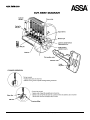
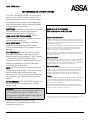
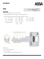
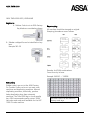
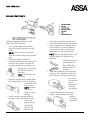
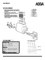
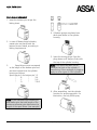
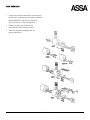
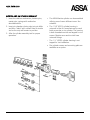
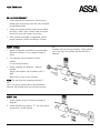
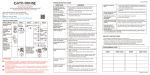
ASSA TWIN 6000
Technical Service Manual
An ASSA ABLOY Group Company
ASSA TWIN 6000
An ASSA ABLOY Group Company
ASSA TWIN 6000
THE UNPARRALLELED SECURITY CYLINDER
The ASSA Twin 6000 cylinder is a high security
option for any ASSA lock and retrofits most
other manufacturer’s locks. A specially shaped
key simultaneously operates two independent
locking mechanisms. Both the key and sidebar
incorporate precision coding.
MATERIALS. Cylinder housing and inner plug are
high-quality brass. Pins are stainless steel,
hardened stainless steel or nickel silver.
MANUFACTURER TOLERNANCES. Precision
machining insures smooth, positive operation
and extended cylinder life.
DRILL RESISTANCE. In addition to side and
tumbler pins, case-hardened drill-resistant
inserts are embedded in the cylinder plug and
housing.
PICK RESISTANCE. ASSA Twin 6000 cylinders
have two independent shear lines that help
assure optimum pick resistance. “False” grooves
in the side pins catch the sidebar when
improperly positioned. When rotational force is
applied, countermilling in the cylinder plug
catches the spool driver pins.
KEYS. ASSA Twin keys are manufactured from
quality nickel silver material. The key’s rounded
back facilitates smoother operation and
minimize wear. The large key bow simplifies key
identification, and use by manually impaired
people.
OTHER DESIGNS. ASSA Twin 6000 cylinders are
available in different shapes for use in many
types of locks.
PATENTS. Existing U.S patents and those existing
and pending in over two dozen manufacture or
use of unauthorized keys or cylinders. Any
infringement of the ASSA patents rights will be
forcefully prosecuted in court.
HIGH SECURITY CYLINDERS
FOR DEMANDING APPLICATIONS
Mortise and Rim Type Cylinders
ASSA 6000 mortise and rim cylinders are designed to replace original
cylinders in many types of common locks. Made to standard dimensions
and available in a variety of finishes, these reliable cylinders stand up to
the heaviest use imaginable.
ASSA 6000 mortise cylinders will improve the security of locks installed
in aluminum storefront doors, as well as standard mortise locks by
Schlage, Yale, Sargent, and other manufacturers. They also can be
applied to a wide variety of special locking devices.
Rim-type 6000 cylinders are designed for commercial exit and panic
devices, as well as vertical deadbolt locks commonly used on apartment
and condominium doors.
Key-In-Knob Cylinders
Knob locks by Schlage, Yale, Russwin, Sargent, and other manufacturers
can be retrofitted with ASSA 6000 high security cylinders. Specifically
engineered shapes replace only the original cylinder – greatly improving
key control without the cost of replacing the entire lock!
High Security Deadbolts
ASSA 6000 deadbolt locks can be used to replace existing deadbolts or
improve security on other doors. Two types of bolts and strike plates
simplify installation in either wood or metal doors and frames, steel,
saw-resistant deadbolt has full one inch throw. Two models are
available: double-cylinder and single cylinder with inside thumbturn.
Padlocks
Three grades of ASS 6000 padlocks expand the application of master key
systems: they also provide independent security on gates, machines,
vehicles, etc. Case-hardened shackles and ball-locking mechanisms are
housed in brass or steel barrels.
Rekeyable and virtually maintenance free, each ASSA 6000 padlock
offers the same high standards of key control, pick resistance, and rill
resistance common to all ASSA 6000 products.
*One or more of the following U.S. Patents covers ASSA 6000 cylinders, key blanks, and other
components: 4,356.713 – 4.393673 – 4.577.479 – 274.302 – 278.880 – 264.680
Products, equipment, finishes, models,
specifications and availability are subject to
change without notice.
An ASSA ABLOY Group Company
ASSA TWIN 6000
DEPTHS
General Rules
A. No. 1 cut is deepest cut, No. 9 is shallowest.
B. Maximum adjacent cut of 5. Example: 1-6 cut acceptable, not 1-7.
C. Depths: Measure from bottom of key blade to bottom of the cut.
No 1 = 4.03 (.1587”)
No 4 = 5.83 (.2295”)
No7 = 7.63 (.3004”)
No 2 = 4.63 (.1823”)
No 5 = 6.43 (.2531”)
No 8 = 8.23 (.3240”)
No 3 = 5.23 (.2059”)
No 6 = 7.03 (.2768”)
No 9 = 8.83 (.3476”)
Cut depths tolerance
+0.00 -- -0.04 mm
+.000” -- -.0016”.
General rules
A. 0.8 mm (.032”) wide base.
B. 90º cutting angle.
C. System and KD code calculated from tip to bow.
An ASSA ABLOY Group Company
ASSA TWIN 6000
ASSA TWIN 6000 KEYS, KEYBLANKS
Key blanks
A. Sidebar Code is cut at ASSA Factory.
Key blanks are provided as shown.
Key stamping
All new keys should be stamped as original.
Stamping procedures are as follows.
B. Sidebar code/profile can be identified on key
bow.
Example 545-50
Decoder for KD/KA combinations.
Count from tip to bow.
Example: EAEGJC = 126958
Key cutting
Sidebar code is pre-cut at the ASSA Factory.
Pin Tumbler Codes can be cut on most code
machines and duplicating machines. Manual
duplicating machines, historically, produce
better duplicating keys than automatic
machines. The Twin 6000 key is a hefty quality
key. ASSA recommends quality cutters. ASSA
has cutter and code cards available for the HPC
1200 CN code machine.
KD Blind Codes can be found on
factory code tags.
An ASSA ABLOY Group Company
ASSA TWIN 6000
SIDE BAR COMPONENTS
Side bar assembly method is for all
ASSA Twin 6000 cylinders
1.
2.
3.
4.
5.
Turn cylinder plug upside down.
Insert the side pin springs into the
holes.
NOTE: These pin holes are drilled
from the bottom side of the cylinder
plug.
Insert the side pins with the
hollowed end towards the spring. Be
sure that the springs and pins are
properly seated in the recesses. If a
spring or pin is jammed,
the cylinder will not
function,
NOTE: All side pins are
the same.
Keep the cylinder plug upside down
and insert the key, for that cylinder,
to keep the side
pins in place.
NOTE: Depress
side pins in
order to insert
the key.
Insert the short springs (side bar
springs) in the small holes at each
end of the
groove along
the cylinder
plug for the
side bar. Be
6.
7.
sure that the springs seat correctly.
Place the side bar so that the shelves
(lug) correspond to the deep waist
of the side pins. Press the side bar
into groove so that it can be fully
depressed into the cylinder plug.
NOTE: The key should be kept in the
cylinder plug at all times during
assembly.
If side bar does not
fully depress into
the cylinder plug,
side bar may be
inverted.
Slide the cylinder plug into cylinder
housing. If the position of the side
bar is correct, the cylinder plug will
turn. Hold
the cylinder
plug in
place when
drawing
out the key.
Fasten the tail piece and the tail
washer. After assembly, test the
cylinder
for proper
operation.
An ASSA ABLOY Group Company
ASSA TWIN 6000
PIN TUMBLER ASSEMBLY
PIN TUMBLER CODE Example
Cylinder bitting
27838 = Bottom pins
314 = Master pins
ABDBAB = Spool drivers
Key bitting
248424 = Chance Key combination
248738 = Master key combination
NOTE:
Always start from the tip of the key
An ASSA ABLOY Group Company
ASSA TWIN 6000
PIN TUMBLER ASSEMBLY
1. Insert the bottom pins as per the
bitting sheet.
4. Cylinders springs are placed over
each spool driver in the cylinder
housing
2. In case of Master-keyed cylinders,
master pins are placed over the
bottom pins as stated, according to
bitting requirements.
5. Insert the closing plugs. Press the
plugs down until they are flush with
the top of the cylinder housing.
3.
Spool drivers must correspond
to the length of the bottom pins and
are then inserted onto the cylinder
housing as follows:
Spool top pin A for bottom pin 1-2
“
B
“
3-4
“
C
“
5-6
“
D
“
7-8-9
Note: Care should be taken not to
damage the finish of the cylinder if
hammering. Other methods of plugging
apply to other types of ASSA cylinders.
6. After assembling, test the cylinder
function for proper operation. For
lubrication, use only ASSA spray.
Note: In pin chambers with bottom pin
and master pins the total length of the
bottom and master pins determines the
length of the spool drives. (see example)
An ASSA ABLOY Group Company
ASSA TWIN 6000
1.
Insert the side bar mechanism, bottom pins,
master pins and springs with same method a
described earlier. See the line drawing
for the location of the components.
2.
Fasten the tail piece and the tail
piece washer with the tail screws.
3.
After the cylinder assembly test for
proper operation.
An ASSA ABLOY Group Company
ASSA TWIN 6000
MORTISE AND RIM CYLINDER ASSEMBLY
1. Insert the side bar mechanism, bottom pins,
master pins, springs with method as
described earlier.
a.
The ASSA Mortise cylinder can be assembled
utilizing one of seven different cams. See
schedule.
2. Insert pin chamber closing strip into pin bible
and then “stake” with a small chisel or similar
tool so the strip will remain in position.
b.
The 1 1/8” (6551) cylinder housing is
universal in that it is manufactured to work
both as mortise or rim cylinder. The housing
is both threaded mortise and tapped for rim
screws. Mortise cams and rim tails have
universal fittings.
c.
The 1 ¼” (6552) cylinder housing is not
tapped for rim installation.
d.
Rim cylinder screws and mounting plate are
available as an option.
3. After the cylinder assembly test for proper
operation.
An ASSA ABLOY Group Company
ASSA TWIN 6000
KEI-IN-KNOB ASSEMBLY
1.
Insert the side bar mechanism, bottom pins,
master pins and springs with the same method
as described earlier.
2.
Insert pin chamber closing strip into pin bible
and then “stake” with a small chisel or similar
tool so the strip will remain in position.
3.
After cylinder assembly is completed, test for
proper operation before installing in lockset.
65611 Schlage
1.
Break off tailpiece provided to accommodate
different functions. Cut to proper length at
score.
2.
The tailpiece can be located in either
vertical
or horizontal positions.
3.
When installing the tailpiece – depress
cylinder
cap pin and tighten cap clockwise until is
tight,
then back off one or two notches.
pin
chamber will not line up properly. If the cylinder
cap is too tight the cylinder will be difficult to
operate.
Note: The cap must be properly adjusted. If
the
cap is too loose the key cannot be withdrawn
because the cylinder plug and cylinder housing
65631 Yale
1. Install cylinder plug in housing as shown in
diagram.
2. Install cylinder pug retainer “C” clip from above
and ensure it is well seated.
An ASSA ABLOY Group Company
ASSA TWIN 6000
EQUIPMENT AND SUPPLIES
Pin kit, tools, and samples
Order No. PK-2
Order No. 96 90 20
Pin Kit includes 100 pieces of size each
bottom, master and drive pins, 500 tumbler
springs, 50 sidebars, 100 each side pins and
sidebar springs, 100 Phillips cam screws, and
25 mortise/rim cover strips.
ASSA Twin code card for HPC 100 CM
Order No. 86 90 18
Deadbolt Sample Mount (base only).
ASSA Twin cutter wheel for HPC 1200 CM
90º/.032”
Order No. 87 26 30
Order No. 90 70 09
Clear Deadbolt Mounting Ring.
Order No. 90 03 05
ASSA Twin Mortise Cutaway.
ASSA High Security Locks
3475 14th Avenue
Markham, ON L3R 0H4
Canada
Phone:
905 940-2040
Fax:
905 940-3242
An ASSA ABLOY Group Company