1
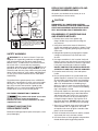
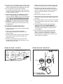
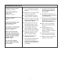
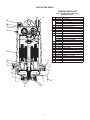
MG200 SERIES GRINDER PUMPS INSTALLATION AND SERVICE MANUAL 2 HP Grinder Pump for Residential and Pressure Sewer Applications. NOTE! To the installer: Please make sure you provide this manual to the owner of the equipment or to the responsible party who maintains the system. Part # 23833A664 | © 2015 Pentair Ltd. | 02/09/15 USAGE CAUTION! The MG200 Series is a submersible wastewater grinder pump designed specifically for individual residential and pressure sewer applications. The pumps are to be used for domestic sewage only and are not to be used for pumping commercial or industrial sewage such as from motels, schools, apartments, factories, etc. THIS PUMP IS NOT FOR USE IN HAZARDOUS LOCATIONS! THE MG200 SERIES GRINDER PUMP SHOULD NEVER BE WORKED ON WITHOUT FIRST DISCONNECTING THE POWER CORD. OIL TYPE The motor housing contains dielectric transformer oil to provide good heat transfer and lubrication of ball bearings; no other lubrication is required. Oil level may be checked by removing the nut and washers from the top of the motor housing. The oil level should be filled to the bottom of the end shield. Do not overfill with oil. Only dielectric transformer oil obtained from a Myers® authorized service center should be used. INSPECTING PUMP Before making any piping or electrical connections, check the pump for shipping damage or cracks. Using a flat screwdriver placed in the slot on the shaft end, turn shaft and impellers to be sure they are free. DO NOT TURN IMPELLER WITH FINGERS AS EDGES ARE SHARP. PUMP SWITCH INSTALLATION INSTRUCTIONS POWER SUPPLY NOTE: In accordance with third party approval, pump must be submerged a minimum of 8-1/2" from bottom of the legs on volute case during operation. The MG200 Series grinder pump should be connected only to a 230 volt, single-phase, 60 Hz power source. The pump will draw approximately 9.1 amperes at minimum flow and 15.0 full load amperes. The pump must be connected to a grounded power socket. DO NOT cut off the ground pin from the power cord plug. Mounting the Switch 1.Determine pumping range for installation. Do not tether less than 3-1/2" from pipe. POWER CORD 2.Tighten strap around discharge pipe keeping switch cable between strap and pipe to prevent slippage. A 20 foot power cord is attached to the grinder pump via three insulated quick-disconnect terminals. To replace a cord simply unscrew (turn counterclockwise) cord nut from top of motor housing. Once cord nut is completely loosened from housing, gently pull cord upward away from housing. While cord is being pulled, it may be necessary to shift cord leads back and forth to guide the insulated terminals through the hole in the motor housing. Once the terminals have cleared the hole, gently pull cord until terminals are completely outside motor housing. Then simply disconnect terminals to remove cord. 3.Space small ties at least 1" apart. To readjust ties, press small tie tabs down. 4.To lock releasable tab, run remaining strap between tab and head. Tuck strap back through head. Piggyback Plug Install To install new cord, reconnect terminals (black to black, white to white, green to green) and guide terminals back through hole in motor housing. Once terminals have passed through the hole, retighten the cord nut into housing. Tighten nut firmly but do not overtighten. Electrical outlet must not be located in pump chamber. Electrical outlet voltage, piggyback plug voltage, and pump voltage must match. 1.Follow steps 1 through 4 of “Mounting the Switch.” 2.Insert switch’s piggyback plug into outlet. 3.Plug pump into piggyback plug. 4.Check installation. Allow system to cycle to ensure proper operation. The power cord should be replaced if it has been damaged in any way or the cord jacket has become brittle. Direct Wire Install 1.Follow steps 1 through 4 of “Mounting the Switch.” MOTOR TYPE 2.Further wiring of switch should be done by qualified professionals only. The MG200 Series grinder pump contains a 3/4 frame, 2 hp, single-phase, 60 Hz, 3450 rpm, capacitor start, capacitor run motor with Class F insulation and built-in, on-winding overload protection. Motor has upper and lower ball bearings and is oil-cooled and lubricated. 3.Check installation. Allow system to cycle to ensure proper operation. 2 230 VAC junction box REPLACING GRINDER IMPELLER AND GRINDER SHREDDING RING All repairs must be done at the factory or at an authorized Myers service facility. L1 L2 G 230V power source CAUTION! black WARNING L1 L2 G G white DISCONNECT ALL POWER AND CONTROL WIRES TO MOTOR AT CONTROL PANEL BEFORE STARTING DISASSEMBLY OPERATIONS. NEVER RELY ON OPENING CIRCUIT BREAKER ONLY. liquid-tight connector 230V pump DISASSEMBLY OF SHREDDING RING AND GRINDER IMPELLER 1.Remove three screws from grinder ring flange. Grinder ring is pressed into flange for easy removal. In 230 VAC pump installations, one side of the line going to the pump is always HOT. This condition exists if the switch is on or off. Install double pole disconnect on all 230 VAC pump circuits. 2.Using Allen head socket wrench, thread two screws into tapped back-off holes in flange. Evenly tighten screws to guide grinding ring out of pump volute case. 3.Hold grinder impeller by prying against impeller cutting bar and remove cap screw from end of shaft. SAFETY WARNINGS WARNING! Risk of electrical shock. Pumps are supplied with a grounding conductor and groundingtype attachment plug on the power cord (except MG200-21L/P). To reduce the risk of electrical shock, be certain that it is connected only to properly grounded, grounding-type receptacle. DO NOT cut off ground pin or use an adapter fitting. DO NOT use an extension cord with this pump. When wiring this pump follow all local electrical, safety codes and ordinances as well as most recent National Electric Code (NECANSI/NFPA). 4.Use large screwdriver in slot in end of shaft and bump on cutter vane with plastic hammer. Bump in counterclockwise direction as thread is right-hand. It may take several bumps to loosen impeller. DO NOT CONTINUE TO POUND ON IMPELLER AS IMPELLER AND SHAFT MAY BE DAMAGED. 5.If impeller comes off easily, clean and replace if worn. 6.Be sure pump impeller has not loosened when grinder impeller is removed. This can be checked on reassembly of grinder impeller and shredding ring. Tips of impeller cutter vanes should extend about 1/8" below bottom of shredding ring. If distance is more, it means the pump impeller has loosened, and if it is less, it means the shredding ring is not properly seated. The MG200 Series grinder pumps have a GROUND WIRE that is connected to a screw in the metal motor housing. This wire goes to the receptacle or control box which must be connected to a good outside GROUND such as a metal water pipe or GROUND STAKE driven at least 8 feet into the ground. If the pump impeller has loosened, remove grinder impeller and shredding ring as described above and remove bolts from volute case and remove case. Plastic hammer can be used to bump on casing discharge to loosen. Place gasket in oil to prevent drying out. DO NOT loosen the pump impeller further – it is the seat for the seal spring. CALIFORNIA PROPOSITION 65 WARNING: This product and related accessories contain chemicals known to the State of California to cause cancer, birth defects or other reproductive harm. 7.After case is removed, wrap emery paper around shaft and hold with vice grip pliers. Use cloth on impeller and screw up against shoulder. Now pump can be reassembled. DISMANTLING PUMP FOR REPLACEMENT PARTS Before dismantling pump for replacement parts, clean pump thoroughly. 8.Clean all threads with wire brush and file; smooth any threads that may have been nicked. 9.Use Never-Seez® or other graphite compound on threads before replacing grinding impeller. 3 10.Be sure cap screw in bottom of shaft is tight. Hold impeller with a screwdriver between cutter bar and teeth of shredding ring while tightening cap screw. 5.Slide motor housing up far enough to expose the capacitors and to be able to lay the housing down. 6.Disconnect wiring from capacitor and loosen capacitor clamp and slide capacitor out. Replace with new capacitor, tighten clamp and reconnect. 11.Be sure impeller turns freely by hand after reassembly. Some drag will occur due to the seal, but there should be no binding or tight spots when turning the grinder impeller. 7.Check all wiring connectors to be sure they are secure. 12.If impeller rubs or drags on shredding ring, loosen bolts in shredding ring plate and tap with plastic hammer to loosen; retighten screws. Be sure to pull screw down evenly, applying pressure on all three screws. DO NOT TIGHTEN ONE SCREW CLEAR DOWN BEFORE ADJUSTING OTHER SCREWS. 8.Be sure tetraseal gasket is in place. 9.Slide motor housing back onto pump while pulling the cord out slowly. Assemble motor housing with four bolts. 10.Reassemble cord nut. Be sure washers are seated and cord is pulled up against the washers. Tighten nut securely. 13. ALWAYS use a rag on the impeller when turning to prevent cutting hands on the sharp corners of shredding ring. 11.Put pump upright and refill motor with Myers submersible pump oil. DO NOT OVERFILL WITH OIL. Reassemble washer, gasket and nut in motor housing. Retighten nut firmly, but do not overtighten. TO REPLACE CAPACITORS ONLY 1.Remove oil fill plug near the top of motor housing and pour oil out. 12.Be sure pump turns freely before connecting power. Turn pump on side and turn impeller, using screwdriver in slotted shaft. Plug pump into receptacle to test operation. Pump must run quietly and free of vibration. 2.Loosen the cord nut on power cord until cord is loose enough to push cord down into motor housing. 3.Remove four bolts from motor housing and bump housing with a plastic hammer to loosen. Lay pump on its side. 4.Remove the housing carefully to be sure that enough cord is pushed into the housing so as not to create tension on cord. WIRING DIAGRAM – AO SMITH® WIRING DIAGRAM – MARATHON® WIRING SCHEMATIC PROTECTOR SENSATA TECHNOLOGIES TYPE 15HM2412 RUN CAPACITOR 20 µF 370 V BROWN ORANGE START CAPACITOR WHITE RED BLUE 324 µF - 389 µF 125 V BLACK PHASE MAIN YELLOW 2 1 3 4 5 6 LINE START CAPACITOR LINE RUN CAPACITOR 4 TROUBLESHOOTING GUIDE Pump does not run or hum. See A, B, C, D, E or F. A. Line circuit breaker may be off; or fuse, if used, may be blown or loose. Pump runs but does not deliver water. See G, H, I, J, K or L. B. Water level in sump may be too low. Run in more water. Pump runs and pumps out sump but does not stop. See M. Pump runs but delivers only small amount of water. See I, J, K, L or N. Fuse blows or circuit breaker trips when pump starts. See K, L, N, O or P. Motor runs for short time then stops. Then after short period starts again. Indicates tripping overload caused by symptom shown. See K, L, N or P. For any other symptoms contact a Myers authorized service facility. C. Pump cord plug may not be making contact in receptacle. D. If pump is using the series cord plug, the two plugs may not be plugged tightly together. E. Float may be stuck. Be sure float operates freely in basin. Check tether length of switch. F. If all symptoms check OK, motor winding may be open; take to service center for repair. G. Check valve may be installed backward. Arrow on valve points in direction of flow. H. Discharge shut-off valve, if used, may be closed. I. Pump may be air locked. Start and stop several times by plugging and unplugging cord. Check vent hole on pump case for plugging. 5 J. Pump head may be too high. Horizontal distance does not affect pumping, except loss due to friction. K. Inlet holes in pump base may be clogged. Remove pump and clean out openings. L. Impeller or volute openings may be plugged or partially plugged. Remove pump and clean. Check tether length of switch. M. Float is stuck in up position. Be sure float operates freely in basin. N. Pump impeller may be partially clogged causing motor to run slow, resulting in motor overload. O. Fuse size or circuit breaker is too small. Must be 20 amps. P. Defective motor stator. Return to Myers service center. MOTOR END PARTS COMMON PARTS LIST For use with product built with Marathon® motor. 6 Ref. 1 2 20 19 18 17 16 3 4 5 6 7 8 9 10 11 12 13 14 15 16 17 18 19 20 – – 15 14 13 12 13 11 10 9 8 7 1 4 5 3 2 6 Part Number 26433D002 21584B000 21584B002 21584B004 19099A012 21583B000 07597A018 25338B001 21582B000 05013A039 26434C010 26434C000 22640C013 26434C060 26430D001 05014A181 25327D000 19100A012 21576A010 26466C200 05022A092 05030A235 05014A193 05030A234 25341A002 145700041 12141A000 Description CASE, VOLUTE FLANGE, W/SHREDDING RING MG200 FLANGE, W/SHREDDING RING MGH200 FLANGE, W/SHREDDING RING MG200F SCREW, CAP 1/4" x 1" LONG., SST (3 REQ’D) RETAINER, IMPELLER, SST SCREW, FLAT HEAD, 1/4" x 3/4" LONG CORD, POWER IMPELLER, GRINDING SCREW, SET 1/4" x 3/8" LONG (2 REQ’D) IMPELLER, PUMP PLASTIC MG200 IMPELLER, CAST IRON (OPTIONAL) MG200 IMPELLER, DUCTILE IRON MGH200 IMPELLER, PLASTIC MG200F PLATE, SEAL/BEARING GASKET, TETRASEAL 7" x 6-3/4" x 1/8" HOUSING, MOTOR SCREW, CAP, 5/16" x 1-1/4" LONG (8 REQ’D) SEAL, 7/8" SHAFT MOTOR, 230V, 1f, 2 HP PLUG, PIPE 1/4 NPT WASHER, SST, 3/32" THICK GASKET, RUBBER WASHER, SST, 1/32" THICK NUT, SOLID RUN CAPACITOR START CAPACITOR THIS PAGE INTENTIONALLY LEFT BLANK STANDARD LIMITED WARRANTY Pentair Myers® warrants its products against defects in material and workmanship for a period of 12 months from the date of shipment from Pentair Myers or 18 months from the manufacturing date, whichever occurs first – provided that such products are used in compliance with the requirements of the Pentair Myers catalog and technical manuals for use in pumping raw sewage, municipal wastewater or similar, abrasive-free, noncorrosive liquids. during the warranty period and subject to the conditions set forth, Pentair Myers, at its discretion, will repair or replace to the original user, the parts that prove defective in materials and workmanship. Pentair Myers reserves the right to change or improve its products or any portions thereof without being obligated to provide such a change or improvement for prior sold and/or shipped units. Start-up reports and electrical schematics may be required to support warranty claims. Submit at the time of startup through the Pentair Myers website: http://forms.pentairliterature.com/startupform/startupform.asp?type=m. Warranty is effective only if Pentair Myers authorized control panels are used. All seal fail and heat sensing devices must be hooked up, functional and monitored or this warranty will be void. Pentair Myers will cover only the lower seal and labor thereof for all dual seal pumps. under no circumstance will Pentair Myers be responsible for the cost of field labor, travel expenses, rented equipment, removal/reinstallation costs or freight expenses to and from the factory or an authorized Pentair Myers service facility. this limited warranty will not apply: (a) to defects or malfunctions resulting from failure to properly install, operate or maintain the unit in accordance with the printed instructions provided; (b) to failures resulting from abuse, accident or negligence; (c) to normal maintenance services and parts used in connection with such service; (d) to units that are not installed in accordance with applicable local codes, ordinances and good trade practices; (e) if the unit is moved from its original installation location; (f) if unit is used for purposes other than for what it is designed and manufactured; (g) to any unit that has been repaired or altered by anyone other than Pentair Myers or an authorized Pentair Myers service provider; (h) to any unit that has been repaired using non factory specified/oEM parts. Warranty Exclusions: PEntAiR MYERS MAKES no EXPRESS oR iMPLiEd WARRAntiES thAt EXtEnd bEYond thE dESCRiPtion on thE FACE hEREoF. PEntAiR MYERS SPECiFiCALLY diSCLAiMS thE iMPLiEd WARRAntiES oF MERChAntAbiLitY And FitnESS FoR AnY PARtiCuLAR PuRPoSE. Liability Limitation: in no EVEnt ShALL PEntAiR MYERS bE LiAbLE oR RESPonSibLE FoR ConSEQuEntiAL, inCidEntAL oR SPECiAL dAMAGES RESuLtinG FRoM oR RELAtEd in AnY MAnnER to AnY PEntAiR MYERS PRoduCt oR PARtS thEREoF. PERSonAL inJuRY And/oR PRoPERtY dAMAGE MAY RESuLt FRoM iMPRoPER inStALLAtion. PEntAiR MYERS diSCLAiMS ALL LiAbiLitY, inCLudinG LiAbiLitY undER thiS WARRAntY, FoR iMPRoPER inStALLAtion. PEntAiR MYERS RECoMMEndS inStALLAtion bY PRoFESSionALS. Some states do not permit some or all of the above warranty limitations or the exclusion or limitation of incidental or consequential damages and therefore such limitations may not apply to you. no warranties or representations at any time made by any representatives of Pentair Myers shall vary or expand the provision hereof. 1101 MYERS PARKWAY AShLAnd, ohio, uSA 44805 419-289-1144 WWW.FEMYERS.CoM Warranty Rev. 12/13 490 PinEbuSh RoAd, unit #4 CAMbRidGE, ontARio, CAnAdA n1t 0A5 800-363-PuMP