1
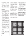
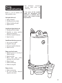
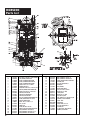
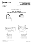
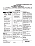
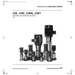
Pump Installation and Service Manual
HGRS200
Submersible Grinder Pump
R
NOTE! To the installer: Please make sure you provide
this manual to the owner of the pumping equipment or to
the responsible party who maintains the system.
General
Information
Thank you for purchasing your
Hydromatic® pump. To help
ensure years of trouble-free
operation, please read the following
manual carefully.
Before Operation:
Read the following instructions
carefully. Reasonable care and
safe methods should be practiced.
Check
local
codes
and
requirements before installation.
Attention:
This manual contains important
information for the safe use of
this product. Read this manual
completely before using this
product and refer to it often for
continued safe product use.
DO NOT THROW AWAY OR
LOSE THIS MANUAL. Keep it
in a safe place so that you may
refer to it often.
WARNING: Before handling
these pumps and controls,
always disconnect the power
first. Do not smoke or use
sparkable electrical devices or
flames in a septic (gaseous) or
possible septic sump.
Pump Cautions
and Warnings
To reduce risk of electrical shock:
1. Risk of Electrical Shock:
This pump has not been
investigated for use in
swimming pool areas.
2. Risk of Electrical Shock:
Connect only to a properly
grounded receptacle.
2
Septic tank to be vented
in accordance with local
plumbing codes.
Do not smoke or use sparkable
electrical devices or flame in a
septic (gaseous) or possible
septic sump.
If a septic sump condition may
exist and if entry into sump is
necessary, then (1) provide
proper safety precautions per
OSHA requirements and (2)
do not enter sump until
these precautions are strictly
adhered to.
Do not install pump in location
classified
as
hazardous
per N.E.C., ANSI/NFPA
70 - 2000.
Failure to heed above
cautions could result in
injury or death.
1. CAUTION – To reduce risk of
electrical shock, pull plug
before servicing this pump.
2. WARNING – Risk of electrical
shock. This pump has not
been investigated for use in a
swimming pool.
3. WARNING – See installation
and service manual for
proper installation.
4. WARNING – To reduce risk
of electrical shock, pump is
provided with grounding wire.
Be certain that it is connected
to ground.
5. WARNING
–
Hazardous
moving parts. To reduce the
risk of injury, disconnect
power before servicing pump.
6. CAUTION – To reduce the risk
of electrical shock, DO NOT
remove cord or strain relief.
DO NOT connect conduit to
pump. Electrical installations
shall be in accordance with
the National Electrical Code
and all applicable local codes
and ordinances. This marking
is required on 3-phase
models only.
7. CAUTION – For use with
maximum 140°F water.
8. CAUTION – Tank should be
vented in accordance with
local plumbing codes and
should not be installed
in locations classified as
hazardous, in accordance with
the National Electrical Code,
ANSI/NFPA 70-1999.
9. CAUTION – Risk of electrical
shock. Do not remove cord and
strain relief. Do not connect
conduit to pump.
10.WARNING – Severe injury
may result from accidental
contact with moving cutters.
Keep clothing, hands and feet
away from cutters any time
power is connected to the pump.
11.CAUTION – Never work on
pump with power on. Make
sure that the ground wire is
securely connected and that the
unit is properly grounded in
accordance with local codes.
Pump
Installation
Installing Pump in Sump:
Before installing pump in sump,
lay it on its side and rotate
impeller. Impeller may be
slightly stuck due to factory test
water so it must be broken loose
with a small bar or screwdriver in
edge of vanes. The impeller
should turn freely. Do not connect
the power until after this test.
Clean all trash and sticks from
sump and connect pump to piping.
A check valve must be installed
on each pump.
Location:
If pumps are installed in an
existing basin or concrete sump,
the piping can either be connected
permanently or rails and brackets
can be furnished for mounting
to walls of basin. In either case,
be sure that the pumps are
submerged in a vertical position.
The
complete
factory-built
packaged system is recommended
for the most satisfactory
installation and generally for the
lowest cost where expensive
installation labor is involved.
Making Electrical Connections:
All electrical wiring must be in
accordance with local code, and
only qualified electricians should
make the installations. Complete
wiring diagrams are included for
use in making the installation. All
wires should be checked for shorts
to ground with an ohmmeter or
Megger after the connections are
made. This is important, as one
grounded wire can cause
considerable trouble.
Pump
Operation
Starting the Pump:
WARNING: Severe injury may
result from accidental contact
with moving cutters. Keep
clothing, hands and feet away
from cutters any time power is
connected to the pump.
To start the pump, perform the
following steps in order:
1. Grinder pump is single phase;
no rotation check is necessary.
2. Run water into sump until
motor is covered.
3. Open gate valve in discharge
line.
4. Turn pump on. If pump runs
and sump liquid does not pump
down, stop pump and close
discharge gate valve. Then lift
pump until sealing flange is open
to vent off trapped air. Lower
pump, open discharge valve,
and start the pump again.
5. Level control should be set so
that pump turns off when level
is about 2 inches above inlet
of pump suction and turns on
when level is about 2 inches
above motor.
6. If problems occur check power
source. Make sure a separate
supply line is available. Verify
voltage supply.
7. Check resistance of windings.
If not within guidelines,
return pump to authorized
Hydromatic service or repair
center.
As the motors are oil filled, no
lubrication or other maintenance
is required. Pump should be
checked every quarter for
corrosion and wear.
Pump
Servicing
Read the following instructions
carefully before replacing any
parts. Reasonable care and safe
methods should be practiced.
Check
local
codes
and
requirements before installation.
Only a competent electrician
should make the installations.
CAUTION: Never work on
pump with power on. Make sure
that the ground wire is securely
connected and that the unit
is properly grounded in
accordance with local codes.
CAUTION: Severe injury may
result from accidental contact
with moving cutters. Keep
clothing, hands and feet away
from cutters any time power is
connected to the pump.
Replacing Grinder Parts:
If necessary to replace grinder
parts because of wear or to inspect
for clogging:
1. Close gate valve at pump
discharge.
2. Turn off circuit breaker.
CAUTION: Never work on
pump with power on. Be sure
ground wire from pump is
connected to a good ground
such as a water pipe.
3. Remove pump from sump.
4. Unscrew screws (3) and
remove cutter ring assembly.
Stationary cutter (2) cannot be
removed from volute.
5. Unscrew hex head cap screws
(11) and remove volute
case (1).
6. Radial cutter (6) is now
exposed. If checking for
clogging, it can now be
cleaned without removing
from the shaft.
7. If necessary to replace
cutter, remove screw (5),
washer (4), and radial cutter
(6) from shaft. Radial cutter
(6) and impeller (8) are
screwed onto shaft. The thread
is right-hand. Tap radial cutter
(6) with plastic hammer if
necessary to loosen. Unscrew
impeller (8) from shaft in same
manner as radial cutter (6).
3
CAUTION: Do not reuse old
seal parts. Replace all parts
with new. Mixing old and new
parts could cause immediate
seal failure.
10.Refill motor housing with
a good quality paraffinic
oil (23). Fill the motor housing
so that the tops of the motor
windings have been covered,
but leave an air gap to allow
for expansion of the oil.
NOTE: It is normal to observe
some air bubbles in the seal
area initially as the seal seats. If
bubbles do not stop within a few
seconds, the seal is either not
properly installed or is damaged.
9. Reassemble the cutter and
volute as outlined in the
replacing grinder parts section
of this manual.
WARNING: Severe injury may
result from accidental contact
with moving cutters. Keep
clothing, hands and feet away
from cutters any time power
is connected to the pump.
PERFORMANCE CURVE
40
35
120
105
30
90
25
75
20
60
15
45
10
30
5
15
0
0
U.S. GPM
M 3/HR
4
NOTE: When applying power,
be sure the pump is restrained
from turning by holding the
pump at the motor housing, or
by clamping it in a holding
fixture.
HEAD (FEET)
Replacing Seal:
1. Drain the oil from the pump by
removing the fill plug (19)
located on the side of the
motor housing (10).
2. Remove the volute and cutters
per the instructions listed
under the replacing grinder
parts section in this manual.
3. To remove the impeller (8),
secure the shaft by a flat
bladed screwdriver into slot on
end of the shaft. Hold a wood
block against the impeller vane
and tap it with a hammer until
it spins off.
4. Remove the seal (12) rotating
elements by sliding the spring
bellows off the shaft, then
using two screwdrivers, slide
the carbon seal assembly off
by prying on the retaining ring.
5. Using a screwdriver, break the
old stationary portion of the
seal (12) to allow for removal.
6. Take the stationary portion of
the new seal (12), and lube the
rubber material with good
quality dielectric oil. Press
the stationary portion of the
new seal into the seal/bearing
plate (9).
7. Using a good quality dielectric
oil, lube the rubber material on
the carbon seal assembly (12)
and press it on the shaft. Place
the spring bellows on the shaft
as removed.
8. Using a pressure gauge with a
fill stem, pressurize the motor
housing no more than 7 psig
with dried air and check for
leaks. If after several minutes
the gauge reads the same,
the seal is good and you can
continue with assembly.
HEAD (METERS)
8. Clean all parts thoroughly
before
proceeding
with
assembly.
9. Replace case. Replace cutter
ring assembly (2). Screw down
with screws (3).
10.Plug pump into power and
operate for a few seconds only
to ensure parts are not rubbing.
0
5
10
1.7
15
3.4
20
25
5.1
30
6.8
35
40
8.5
10.2
Pump
Troubleshooting
3. No
diametral
clearance
between radial cutter and
cutter ring
Below is a list of troubles and
their probable causes:
If the cause of the trouble
cannot be determined and
corrected as outlined above,
contact your nearest factory
representative.
No liquid delivered
1. Pump airbound
2. Discharge head too high
3. Pump or piping plugged
4. Speed too low
Insufficient liquid delivered
1. Discharge head too high
2. Impeller or cutters partially
plugged or damaged
3. Incorrect impeller diameter
4. Speed too low
Insufficient discharge pressure
1. Air or gases in liquid
2. Impeller damaged
3. Incorrect impeller diameter
4. Speed too low
Pump overloads motor
1. Specific gravity or viscosity of
liquid too high
2. Speed too high
3. Head lower than rating,
pumping too much liquid
4. Pump clogged
5. Defective bearings
6. Defective impeller
Pump is noisy
1. Defective bearings
2. No axial clearance between
impeller and volute
5
HGRS200
Parts List
Ref. No.
1
1A
2
2
2
3
4
5
6
7
8
8
8
9
9A
10
11
12
13
14A
14B
14C
14D
14E
6
Part No.
26433D002
22084A000
21584B000
21584B003
21584B004
19099A012
21583A000
07597A018
21582B000
05013A039
26434C010
26434C013
26434C060
26430D001
05014A181
25327D000
19100A012
21576A010
08565A018
26466C101
26466C002
09859A827
09859A828
09859A829
Description
CASE, VOLUTE; C.I. HGRS200 1-1/4 NPT DISCHARGE
PLATE; WARNING, GRINDER PUMP
FLANGE; W/SHREDDING RING HGRS200
FLANGE; W/SHREDDING RING HGRSH200
FLANGE; W/SHREDDING RING HGRS200F
SCREW; CAP HEX 1/4 SST 1 LG 20UNC
RETAINER; IMPELLER SST
SCREW; MACH FLT HD SKT SST 1/4-20-3A X 3/4LG
IMPELLER; GRINDING SEWAGE GRINDER PUMP
SCREW; SET HDLS HEX SST 1/4-20X3/8 CUP
IMPELLER; PLASTIC HGRS200
IMPELLER; CAST IRON HGRSH200
IMPELLER; PLASTIC HGRS200F
PLATE; SEAL & BEARING HGRS200 GRINDER PUMP
GASKET; RUBBER TETRASEAL 7X6 3/4X1/8
HOUSING, MOTOR HGRS200
SCREW – HHC 5/16-18UNC X 1-1/4
SEAL; 7/8 SHAFT
BEARING, BALL
STATOR; LONG SHELL 2 HP 230V
ROTOR; W/SHAFT FOR HGRS200 GRINDER PUMP
WIRE; W/TERMINALS 14GA BLACK 9 LG.
WIRE; W/TERMINALS 14GA BLACK 4-1/2 LG.
WIRE; W/TERMINALS 14GA YELLOW 4 LG.
Qty.
1
1
1
1
1
3
1
1
1
2
1
1
1
1
1
1
8
1
1
1
1
1
1
1
Ref. No.
14F
14G
14I
16
16A
17
17A
18
19
20
20A
20B
20C
21
22
22A
23
24
25A
25
26A
Part No.
09859A830
09859A831
26466C003
12141A015
20333A001
08565A013
11816A006
19331A005
05022A092
05030A235
05014A193
05030A234
25341A002
25338B001
27601A990
045800011
24709110000
09822A032
20333A004
23838A010
17190A004
12074A064
Description
WIRE; W/TERMINALS 14GA RED 3 LG.
WIRE; W/TERMINALS 14GA WHITE 8 LG.
SWITCH; CENTRIFUGAL MECH. FOR HGRS200
CAPACITOR; START
CLIP; TUBE CAPACITOR MTG ST
BEARING,BALL
RING; RETAINING
WASHER; SPRING FINGER
PLUG; PIPE ST GALV 1/4 HEX HD
WASHER; SST 3/32" THICK
GASKET; RUBBER
WASHER; SST 1/32" THICK
NUT; CORD PLUG,SOLID
CORD; POWER,ASSY,14/3 W/230V PLUG,20FT
NAMEPLATE; 1 PHASE HYDROMATIC
SCREW – DRIVE
PARAFFINIC OIL
SCREW; TAPPING SST 316 SST
CLIP; TUBE CAPACITOR MTG ST
CAPACITOR; RUN
TIE; CABLE NYLON 1 MAX BUNDLE DIA
TERMINAL; INSULATED MALE
Qty.
1
1
1
1
1
1
1
1
2
1
1
1
1
1
1
4
1
2
1
1
1
1
LIMITED PRODUCT WARRANTY
HYDROMATIC warrants that its products are free from defects in material and workmanship for a period of
twelve (12) months from the date of purchase or eighteen (18) months from the date of manufacture, whichever
occurs first.
®
During the warranty period and subject to the conditions hereinafter set forth, HYDROMATIC, will repair or
replace to the original user or consumer parts which prove defective due to defective materials or workmanship
of HYDROMATIC. Contact the nearest authorized HYDROMATIC distributor, HYDROMATIC authorized
service center or HYDROMATIC for warranty service. At all times, HYDROMATIC shall have and possess
the sole right and option to determine whether to repair or replace defective equipment, parts or components.
Start up reports and electrical system schematics may be required to support warranty claims. Warranty is
effective only if HYDROMATIC supplied or authorized control panels are used, where applicable. All dual
seal pumps must have seal failure and heat sensors attached, functional and monitored for the warranty to be
in effect. If a seal failure should occur, HYDROMATIC will only cover the lower seal and labor thereof. If the
heat sensor and seal fail sensor is not attached and functional, the warranty is void.
LABOR, ETC. COSTS: HYDROMATIC shall in NO EVENT be responsible or liable for the cost of field labor,
removal and/or reinstallation charges of any HYDROMATIC product, part or component thereof, or the
expense of freight.
THIS WARRANTY WILL NOT APPLY: (a) to defects or malfunctions resulting from failure to properly install,
operate or maintain the unit in accordance with printed instructions provided; (b) to failures resulting from
abuse, accident or negligence; (c) to normal maintenance services and the parts used in connection with such
service; (d) to units which are not installed in accordance with applicable local codes, ordinances and good
trade practices; or (e) if the unit is moved from its original installation location; (f) unit is used for purposes
other than for what it was designed and manufactured; (g) to any unit which has been repaired or altered by
anyone other than HYDROMATIC, a HYDROMATIC distributor or a HYDROMATIC authorized service
center and (h) to any unit which has been repaired using non factory specified parts/OEM parts.
RETURN OR REPLACED COMPONENTS: any item to be replaced under this Warranty must be returned
to HYDROMATIC in Ashland, Ohio, or such other place as HYDROMATIC may designate, freight prepaid.
PRODUCT IMPROVEMENTS: HYDROMATIC reserves the right to change or improve its products or any
portions thereof without being obligated to provide such a change or improvement for units sold and/or
shipped prior to such a change or improvement.
WARRANTY EXCLUSIONS: HYDROMATIC MAKES NO EXPRESS OR IMPLIED WARRANTIES WHICH
EXTEND BEYOND THE DESCRIPTION ON THE FACE HEREOF. HYDROMATIC SPECIFICALLY DISCLAIMS
THE IMPLIED WARRANTIES OF MERCHANTABILITY AND FITNESS FOR ANY PARTICULAR PURPOSE.
Some states do not permit some or all of the above warranty limitations and, therefore, such limitations may
not apply to you. No warranties or representations at any time made by any representatives of
HYDROMATIC shall vary or expand the provision hereof.
LIABILITY LIMITATION: IN NO EVENT SHALL HYDROMATIC BE LIABLE OR RESPONSIBLE FOR
CONSEQUENTIAL, INCIDENTAL OR SPECIAL DAMAGES RESULTING FROM OR RELATED IN ANY MANNER
TO ANY HYDROMATIC PRODUCT OR PARTS THEREOF. PERSONAL INJURY AND/OR PROPERTY DAMAGE
MAY RESULT FROM IMPROPER INSTALLATION. HYDROMATIC DISCLAIMS ALL LIABILITY, INCLUDING
LIABILITY UNDER THIS WARRANTY, FOR IMPROPER INSTALLATION — HYDROMATIC RECOMMENDS
INSTALLATION BY PROFESSIONALS.
Some states do not allow the exclusion or limitation of incidental or consequential damages, so the above
limitation or exclusion may not apply to you.
This Warranty gives you specific legal rights and you may also have other rights which vary from state to state.
In the absence of suitable proof of this purchase date, the effective date of this warranty will be based upon
the date of manufacture.
– Your Authorized Local Distributor –
USA
740 East 9th Street, Ashland, Ohio 44805
Tel: 419-289-3042 Fax: 419-281-4087
www.hydromatic.com
© 2008 Hydromatic Ashland, Ohio. All Rights Reserved.
®
CANADA
269 Trillium Drive, Kitchener, Ontario, Canada N2G 4W5
Tel: 519-896-2163 Fax: 519-896-6337
Part # 5625-499-1
Item # E-03-499 6/08
START-UP REPORT
Distributor______________________________________________________Order #: _________________
Installing Contractor: _____________________________________ Phone: _________________________
Sales Contact: __________________________________________ Phone: _________________________
Customer & Location _____________________________________________________________________
1.
SYSTEM INFORMATION
A. Size of wet well: __________________________________ Manufacturer:_____________________
B. Discharge from bottom of basin: ___________________ Location: __________________________
C. Inlet from bottom of basin:________________________ Location: __________________________
D. Type of check valves: ______________________________________________________________
E. Type of piping ____________________________________________________________________
F. Does system have suction and discharge gauges? _______________________________________
G. Pressure reading? Suction_____________________ Discharge _________________________
H. Liquid being pumped:____________________ Temperature: __________ % of solid: __________
I. Sketch or photograph of system attached? _____________________________________________
J. Any additional comments on system: __________________________________________________
__________________________________________________________________________________
2.
ELECTRICAL INFORMATION
A. Control panel part #:__________________________
Panel rated amps: ___________________
Manufacturer ___________________________ Voltage: __________ Phase: _____________
B. Heater size: _____________________________________________________________________
C. Location of panel to wet well: ________________________________________________________
D. Incoming line voltage: _________________________ Actual? _____________________________
E. Voltage to pumps ____________________________ Actual? _____________________________
F. Type of junction box: _____________________________ Manufacturer:_______________________
G. Are floats installed in wet well? _______________________________________________________
H. Are floats set to engineer’s spec? ____________________________________________________
I. Are floats wired for proper sequencing? ________________________________________________
J. Any additional comments on electrical: ________________________________________________
__________________________________________________________________________________
3.
PUMP INFORMATION
A. Type of pump:______________________________________ Serial # ______________________
B. Voltage:_____________ Phase:_____________ RPM:_____________ Amps: ___________
C. Impeller size: ______________ C.O.S. TDH:________________ GPM: ___________________
D. Voltage supplied from panel:___________________ Actual?: _____________________________
E. Actual amperage (all phases): _____________ amps _____________amps _____________amps
F. Have you checked pump rotation? ____________________________________________________
G. Any additional comments on pumps: __________________________________________________
__________________________________________________________________________________
Acknowledge that all information is accurate and proper procedures have been followed:
Customer Signature:__________________________________________________ Date ___________
Start-up Technician:__________________________________________________
Date __________
Send to: Warranty Department, 740 E. Ninth Street, Ashland, OH 44805, Fax: 419-207-3344,
or e-mail to: [email protected]
H-02-7590
We will make this a permanent part of our file on this order.
3/08