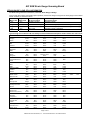
1
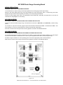
Absolute Process Instruments, Inc.
800-942-0315 www.api-usa.com
API SUM 000
Strain Gauge Summing Board
API SUM 025
Strain Gauge Summing Board with API 4059 G Signal Conditioning Module
Installation – Calibration – Operation
API SUM 000
API SUM 025
Table of Contents
Page
Functional Description....................................................................2
Specifications ..................................................................................2
Board Installation ............................................................................2
Wiring ...............................................................................................3
API SUM 000 Setup..........................................................................4
API SUM 000 Excitation Voltage Calibration .................................5
API SUM 000 Load Cell Calibration................................................6
API SUM 025 Setup..........................................................................7
API SUM 025 Calibration .................................................................8
API SUM 025 Excitation Voltage Calibration .................................9
API SUM 025 Load Cell Calibration..............................................10
API SUM 025 Final Adjustment.....................................................10
API SUM 025Troubleshooting ......................................................11
Strain Gauge (Load Cell) Information ..........................................12
Rev. 09-05
SUMXXXMAN
API SUM Strain Gauge Summing Board
FUNCTIONAL DESCRIPTION
The API SUM 000 Strain Gauge Summing Assembly consists of a sum board and an optional field rangeable strain gauge signal
conditioning module that plugs into the 11-pin socket on the board. The board will accept up to four 350 Ω (or greater) strain
gauges (load cells) and provide an output proportional to the sum of the active strain gauges. The API SUM board can be
mounting in commonly available NEMA enclosures.
If a strain gauge signal conditioning module is not used, the API SUM 000 functions as summing board for the active strain
gauges (load cells). A stable external excitation supply must be connected to the board. The resulting output will be an
unconditioned mVDC signal equal to the sum of the active strain gauges (load cells).
The API SUM 025 Strain Gauge Summing Assembly consists of the sum board and the API 4059 field rangeable strain gauge
signal conditioning module that plugs into the 11-pin socket on the board. The strain gauge signal conditioning module provides
a stable source of excitation (field-rangeable from 1 to 10 VDC) sufficient to power up to four 350 Ω strain gauges (load cells).
The signal conditioner can also be field-ranged for various input sensitivities. The signal conditioner can also be field-ranged for
DC voltage outputs up to ±10 VDC or DC current outputs up to 20 mADC. An offset adjustment on the signal conditioner allows
the user to cancel or “tare” non-zero deadweights in the application. Refer to the data sheet for the API 4059.
Exclusive features of API strain gauge signal conditioning module include two LoopTracker® LEDs and the Functional Test
Pushbutton. The LoopTracker LEDs (green for input, red for output) act as power-on indicators and track the signal strength by
varying in intensity as the process variable changes. The LoopTracker greatly aids in setup and troubleshooting of your system.
The Functional Test Pushbutton, when depressed, will generate an output independent of the input signal. This output is
preset at the factory at 50% of the calibrated output, but can be scaled in the field from 0 to 100% of the selected output via a
top-accessible multi-turn potentiometer.
SPECIFICATIONS
Dimensions
Board only:
Board material thickness:
With API 4059 G:
6.85" Wide X 8.75" High X 0.75" Deep
0.094"
6.85" Wide X 8.75" High X 3.75" Deep
Strain Gauge Inputs
Up to four 350 Ohm (or greater) strain gauges (load cells)
API SUM 025 Signal Conditioning Module Specifications
Power:
115 VAC standard, 2.5 Watts maximum
Optional power:
230 VAC with API 4059 G A230
Optional power:
9-30 VDC using API-4059 G D
API SUM 025 Strain Gauge Excitation Supply
Field-rangeable from 1 to 10 VDC
Strain Gauge Sensitivity/Signal
Field-rangeable sensitivities. Refer to corresponding module data sheet for details.
API SUM 025 DC Voltage or Current Outputs
Field-rangeable DC voltages from –10 VDC to +10 VDC
Field-rangeable DC currents up to 20 mADC at 20 VDC compliance
BOARD INSTALLATION
Ensure proper operation and protection by securely mounting for the API SUM board and strain gauge signal conditioning
module (if used) in an enclosure designed for the environment in which it will be used. Appropriate wire glands must be used to
route wiring into housing.
API will not be responsible for damage that occurs or any code violations due to improper enclosure selection or installation.
Seven mounting holes are provided—one at each corner for securing the board and three surrounding the eleven-pin socket for
added support at the socket.
The board must be spaced a minimum of ¼ inch from the mounting surface using commonly available insulated spacers.
The board must be secured at all four corners. If the signal conditioning module is used, insulated spacers and fasteners MUST
be used for the three mounting holes around the socket as well.
Page 2 of 12
Absolute Process Instruments, Inc. Phone: 800-942-0315 Fax: 800-949-7502
API SUM Strain Gauge Summing Board
WIRING PRECAUTIONS
WARNING! TURN OFF ALL POWER BEFORE WIRING!
To avoid interference, all power wiring must be kept separate from the strain gauge and DC output wiring!
Wiring for each strain gauge (load cell) must be kept separate from other strain gauge, power, or output wiring. Each strain
gauge (load cell) should be routed separately and directly to its corresponding terminal block.
Connect the strain gauges (load cells) to the appropriate terminal blocks LC1, LC2, LC3, and LC4. Refer to the load cell
manufacturer’s wiring diagram for correct wiring.
API SUM 000 WIRING
DISCONNECT POWER TO THE EXCITATION SUPPLY DURING INSTALLATION!
Connect the external excitation supply wiring to terminal block J5, terminals 1 (EXT EXC+) and 2(EXT EXC–). Observe wiring
polarity.
The summed mV output from the strain gauges is present at terminal block J5 terminal 6 OUT – and J5 terminal 7 OUT +. Use
these terminals to connect your external device to read the summed strain gauge output.
Ensure all connections are correctly wired and securely tightened. Proceed to “API SUM 000 SETUP”.
API SUM 025 WIRING
ALL POWER MUST BE DISCONNECTED OR TURNED OFF DURING INSTALLATION!
The summed strain gauge mV signal is converted to a DC voltage or current output by the signal conditioner. This output signal
is present at terminal block J5, terminals 4 and 5. Connect your compatible external device to read the signal output.
See label on signal conditioner for correct operating power. Connect the appropriate power to terminal block J6.
Make sure all connections are correctly wired and securely tightened. Proceed to “API SUM 025 SETUP”.
Page 3 of 12
Absolute Process Instruments, Inc. Phone: 800-942-0315 Fax: 800-949-7502
API SUM Strain Gauge Summing Board
API SUM 000 SETUP
1.
Set slide switch SW2 to the EXT position (up).
2.
The external excitation supply and mVDC output wiring should be connected to terminal block J5.
3.
For each strain gauge (load cell) installed, the corresponding slide switch (SW1) is set to the ON (up) position. The load cell
terminal blocks and slide switches are matched as follows
Terminal Block LC1 = SW1-1
Terminal Block LC2 = SW1-2
Terminal Block LC3 = SW1-3
Terminal Block LC4 = SW1-4
4.
If a strain gauge (load cell) is not being used, slide its corresponding switch to the OFF (down) position. The individual
switches in SW1 are used to electrically add or remove the corresponding load cell. This is useful when less than four load
cells are used or if one or more must be removed for service.
5.
Before calibration, set all Signal Adjust potentiometers (LC1, LC2, LC3, LC4 mounted below SW1) to maximum by turning
fully clockwise (CW). The potentiometers are 25-turn and a slight clicking sound can be heard and/or felt at the endpoint.
The potentiometer will not be damaged by turning beyond the endpoint.
6.
Before calibration, set all Excitation Adjust potentiometers (LC1, LC2, LC3, LC4 mounted above SW1) to maximum by
turning fully clockwise (CW). The potentiometers are 25-turn and a slight clicking sound can be heard and/or felt at the
endpoint. The potentiometer will not be damaged by turning beyond the endpoint.
Page 4 of 12
Absolute Process Instruments, Inc. Phone: 800-942-0315 Fax: 800-949-7502
API SUM Strain Gauge Summing Board
API SUM 000 EXCITATION VOLTAGE CALIBRATION
1.
Measure and record the Excitation Voltage at terminal block J5 terminal 1 (EXC +) and terminal 2 (EXC –).
Terminal Block J5 (EXC – to EXC +): Excitation Voltage ____________ Volts
2.
Measure and record the Excitation Voltage at terminal 1 (EXC +) and terminal 2 (EXC –) of each load cell terminal block
LC1, LC2, LC3, and LC4 that is being used.
Terminal Block LC1 (EXC – to EXC +): Excitation Voltage ____________ Volts
Terminal Block LC2 (EXC – to EXC +): Excitation Voltage ____________ Volts
Terminal Block LC3 (EXC – to EXC +): Excitation Voltage ____________ Volts
Terminal Block LC4 (EXC – to EXC +): Excitation Voltage ____________ Volts
3.
Each voltage reading should be very close or equal to the excitation voltage supplied externally.
3.1. If the voltage readings are equal, skip to “API SUM 000 LOAD CELL CALIBRATION”.
3.2. If they vary by only a few millivolts, skip to step 4.
3.3. If they are zero or vary by more than a few millivolts from the expected voltage, troubleshoot as follows in steps 3.3.1
through 3.3.4.
3.3.1. Confirm that switch SW2 is completely switched to the EXT position and that the individual switches in SW1 are
in the up or ON position. Move the switches to their opposite position and back again to confirm that they have
completely seated in the correct position.
3.3.2. Make sure all Excitation Adjust potentiometers LC1, LC2, LC3, LC4 mounted above SW1 are set at maximum
by turning fully clockwise. The potentiometers are 25-turn and a slight "clicking" sound can be heard and/or felt
at the endpoint. Recheck excitation voltage readings.
3.3.3. If the problem continues, remove the wiring to terminals 1 (EXC +) and terminals 2 (EXC –) of each load cell
terminal block LC1, LC2, LC3, and LC4. Recheck excitation voltage readings.
3.3.4. If the problem goes away, connect each strain gauge one at a time to its corresponding terminal block and
measure the value at terminals 1 and 2. Repeat, as necessary, for the remaining strain gauges. If the problem
re-occurs, check for improper strain gauge wiring and/or a faulty load cell.
4.
If the voltage readings vary by a few millivolts, adjust each Excitation Adjust potentiometer LC1, LC2, LC3, LC4 mounted
above SW1 so that the readings at terminals 1 and 2 of the corresponding terminal blocks are exactly equal to the excitation
voltage required.
Page 5 of 12
Absolute Process Instruments, Inc. Phone: 800-942-0315 Fax: 800-949-7502
API SUM Strain Gauge Summing Board
API SUM 000 LOAD CELL CALIBRATION
1.
Apply the same known test weight sequentially and individually over each load cell. Measure and record the readings at
terminals 4 and 5 (SIG – and SIG +) of each terminal block LC1, LC2, LC3, and LC4. Take care to place the weight directly
over the cell (if possible), or in the same position relative to the cell, each time a reading is taken. This will minimize the
number of times the procedure must be repeated.
Terminal Block LC1 (SIG – to SIG +): Signal Voltage ____________ Volts
Terminal Block LC2 (SIG – to SIG +): Signal Voltage ____________ Volts
Terminal Block LC3 (SIG – to SIG +): Signal Voltage ____________ Volts
Terminal Block LC4 (SIG – to SIG +): Signal Voltage ____________ Volts
2.
Each voltage reading should be very close or equal to each other. If the voltage readings are equal, sum board calibration is
complete and any further calibration or scaling is done at the user’s display or control equipment. If there is any variation,
continue with step 3.
3.
Disable the load cells by sliding the individual switches on SW1 to the OFF (down) position except for the load cell) that had
the highest recorded reading in step 1. It is not necessary to disconnect the load cell wiring. Do not enable any of the other
load cells at this time.
4.
Apply the same test weight from step 1 in the same position over the high-reading load cell.
5.
Connect the volt meter leads to terminal block J5 to read terminals 4 (SIG –) and 5 (SIG +)
6.
While monitoring the reading at J5 SIG – and J5 SIG +, turn the Signal Adjust potentiometer (LC1, LC2, LC3, or LC4
below SW1) corresponding to the enabled cell so that the meter reads the same as the lowest value recorded in step 1.
7.
Repeat steps 3 through 6 for each strain gauge (load cell) that read greater than the lowest reading recorded in step 1. It is
not necessary to adjust the signal potentiometer for the strain gauge (load cell) that had the lowest reading.
8.
Once all necessary adjustments have been made, repeat steps 1 through 7 until the readings are equal. Once all readings
are equal, the sum board calibration is complete and any further calibration or scaling is done at the user’s display or control
equipment.
Page 6 of 12
Absolute Process Instruments, Inc. Phone: 800-942-0315 Fax: 800-949-7502
API SUM Strain Gauge Summing Board
API SUM 025 SETUP
The strain gauge signal conditioning module must be set up and calibrated to match the system requirements (strain gauge
sensitivities, excitation supply voltages, offset, and output).
1.
Make sure the necessary steps on page 3 of this manual have been followed with regard to wiring and correct supply
voltage to the module.
2.
Plug the strain gauge signal conditioning module into the eleven pin socket.
3.
Set slide switch SW2 to the INT position (down). In this position, the API signal conditioner module will supply excitation
voltage to the load cells.
4.
For each strain gauge (load cell) installed, the corresponding slide switch (SW1) is set to the ON (up) position. The load cell
terminal blocks and slide switches are matched as follows
Terminal Block LC1 = SW1-1
Terminal Block LC2 = SW1-2
Terminal Block LC3 = SW1-3
Terminal Block LC4 = SW1-4
5.
If a load cell is not being used, slide its corresponding switch to the OFF (down) position. The individual switches in SW1 are
used to electrically add or remove the corresponding load cell. This is useful when less than four load cells are used or
when one or more must be removed for service.
6.
Before calibration, set all Signal Adjust potentiometers (LC1, LC2, LC3, LC4 mounted below SW1) to maximum by turning
fully clockwise (CW). The potentiometers are 25-turn and a slight clicking sound can be heard and/or felt at the endpoint.
The potentiometer will not be damaged by turning beyond the endpoint.
7.
Before calibration, set all Excitation Adjust potentiometers (LC1, LC2, LC3, LC4 mounted above SW1) to maximum by
turning fully clockwise (CW). The potentiometers are 25-turn and a slight clicking sound can be heard and/or felt at the
endpoint. The potentiometer will not be damaged by turning beyond the endpoint.
Page 7 of 12
Absolute Process Instruments, Inc. Phone: 800-942-0315 Fax: 800-949-7502
API SUM Strain Gauge Summing Board
API SUM 025 CALIBRATION
The strain gauge signal conditioning module can be calibrated separately from the API SUM board or while installed on the
board. If the module has been pre-calibrated for the application, skip to “API SUM 025 EXCITATION VOLTAGE CALIBRATION”.
There are two methods for calibrating the strain gauge signal conditioning module while it is plugged into the API SUM board.
The method you choose will depend upon the test equipment available.
Millivolt Generator Method
1.
The strain gauge signal conditioning module must be plugged into the 11-pin socket.
2.
The power connected to terminal block J6 must match the power required by the strain gauge signal conditioning module,
or damage will occur. When correct, apply power. The Green and Red Loop-Tracker LEDs on the module should
illuminate. If one or both lights do not illuminate, go to the Troubleshooting section.
3.
Disable all strain gauges (load cells) by sliding all four switches of SW1 to the OFF (down) position. It is not necessary to
disconnect the load cell wiring.
4.
Set slide switch SW2 to the EXT (up) position.
5.
Connect an accurate millivolt generator to terminal block J5 terminals SIG – and SIG +.
6.
Connect an accurate voltmeter to terminal block J5 terminals SIG – and SIG +.
7.
Follow the setup and calibration procedures on the data sheet supplied with the module. Use the millivolt generator as the
input and read the output with the digital voltmeter.
8.
Disconnect the millivolt generator and digital voltmeter.
9.
Reposition SW2 to the INT (down) position.
10. Re-enable all active load cells by sliding their corresponding switches on SW1 to the ON (up) position.
11. Skip to “API SUM 025 EXCITATION VOLTAGE CALIBRATION”.
Bridge Simulator Method
1.
The strain gauge signal conditioning module must be plugged into the 11-pin socket.
2.
The power connected to terminal block J6 must match the power required by the strain gauge signal conditioning module,
or damage will occur. When correct, apply power. The Green and Red Loop-Tracker LEDs on the module should
illuminate. If one or both lights do not illuminate, go to the Troubleshooting section.
3.
Disconnect the load cell wiring from terminal block LC1. It is not necessary to disconnect the wiring at LC2, LC3, or LC4.
4.
Turn on LC1 by sliding switch 1 of SW1 to the ON (up) position. Turn off LC2, LC3, and LC4 by sliding switches 2 thru 4 of
SW1 to the OFF (down) positions.
5.
Connect an accurate Bridge Simulator to terminal block LC1 in place of the actual load cell.
6.
Slide switch SW2 must be in the INT (down) position.
7.
Connect an accurate digital voltmeter to terminal block J5 terminals SIG – and SIG +.
8.
Follow the setup and calibration procedures on the data sheet supplied with the module. Use the bridge simulator as the
input and read the output with the digital voltmeter.
9.
Disconnect both the bridge simulator and digital voltmeter. Reconnect the strain gauge (load cell) to terminal block LC1.
Turn on all active load cells by sliding their corresponding switches on SW1 to the ON (up) position.
10. Continue to “API SUM 025 EXCITATION VOLTAGE CALIBRATION”.
Page 8 of 12
Absolute Process Instruments, Inc. Phone: 800-942-0315 Fax: 800-949-7502
API SUM Strain Gauge Summing Board
API SUM 025
1.
EXCITATION VOLTAGE CALIBRATION
Measure and record the Excitation Voltage at terminal block J5 terminal 1 (EXC +) and terminal 2 (EXC –).
Terminal Block J5 (EXC – to EXC +): Excitation Voltage ____________ Volts
2.
Measure and record the Excitation Voltage at terminal 1 (EXC +) and terminal 2 (EXC –) of each load cell terminal block
LC1, LC2, LC3, and LC4 that is being used.
Terminal Block LC1 (EXC – to EXC +): Excitation Voltage ____________ Volts
Terminal Block LC2 (EXC – to EXC +): Excitation Voltage ____________ Volts
Terminal Block LC3 (EXC – to EXC +): Excitation Voltage ____________ Volts
Terminal Block LC4 (EXC – to EXC +): Excitation Voltage ____________ Volts
3.
Each voltage reading should be very close or equal to the excitation voltage supplied externally.
3.1. If the voltage readings are equal, skip to “API SUM 025 LOAD CELL CALIBRATION”.
3.2. If the vary by a few millivolts, skip to step 4.
3.3. If they are zero or vary by more than a few millivolts from the expected voltage, troubleshoot as follows in steps 3.3.1
through 3.3.4.
3.3.1. Confirm that switch SW2 is completely switched to the EXT position and that the individual switches in SW1 are
in the up or ON position. Move the switches to their opposite position and back again to confirm that they have
completely seated in the correct position.
3.3.2. Make sure all Excitation Adjust potentiometers LC1, LC2, LC3, LC4 mounted above SW1 are set at maximum
by turning fully clockwise. The potentiometers are 25-turn and a slight "clicking" sound can be heard and/or felt
at the endpoint. The potentiometer will not be damaged by turning beyond the endpoint. Recheck excitation
voltage readings.
3.3.3. If the problem continues, remove the wiring to terminals 1 (EXC +) and terminals 2 (EXC –) of each load cell
terminal block LC1, LC2, LC3, and LC4. Recheck excitation voltage readings.
3.3.4. If the problem goes away, connect each strain gauge one at a time to its corresponding terminal block and
measure the value at terminals 1 and 2. Repeat, as necessary, for the remaining strain gauges. If the problem
re-occurs, check for improper strain gauge wiring and/or a faulty load cell.
4.
If the voltage readings vary by a few millivolts, adjust each Excitation Adjust potentiometer LC1, LC2, LC3, LC4 mounted
above SW1 so that the readings at terminals 1 and 2 of the corresponding terminal blocks are exactly equal to the excitation
voltage required.
Page 9 of 12
Absolute Process Instruments, Inc. Phone: 800-942-0315 Fax: 800-949-7502
API SUM Strain Gauge Summing Board
API SUM 025 LOAD CELL CALIBRATION
1.
Apply the same known test weight sequentially and individually over each load cell and record the readings at terminals 4
and 5 (SIG – and SIG +) of each terminal block LC1, LC2, LC3, and LC4. Take care to place the weight directly over the
cell (if possible), or in the same position relative to the cell, each time a reading is taken. This will minimize the number of
times the procedure must be repeated.
Terminal Block LC1 (SIG – to SIG +): Signal Voltage ____________ Volts
Terminal Block LC2 (SIG – to SIG +): Signal Voltage ____________ Volts
Terminal Block LC3 (SIG – to SIG +): Signal Voltage ____________ Volts
Terminal Block LC4 (SIG – to SIG +): Signal Voltage ____________ Volts
2.
If the voltage readings are equal, sum board calibration is complete. Any further calibration is done at “API SUM 025 FINAL
ADJUSTMENT”. If there is any variation, continue with step 3.
3.
Disable the load cells by sliding the individual switches on SW1 to the OFF (down) position except for the load cell that had
the highest recorded reading in step 1. It is not necessary to disconnect the load cell wiring. Do not enable any of the other
load cells at this time.
4.
Apply the same test weight from step 1 in the same position over the high-reading load cell.
5.
Connect the voltmeter leads to terminal block J5 to read terminals 4 (SIG –) and 5 (SIG +)
6.
While monitoring the reading at J5 SIG – and J5 SIG +, turn the Signal Adjust potentiometer (LC1, LC2, LC3, or LC4
below SW1) corresponding to the enabled cell so that the meter reads the same as the lowest value recorded in step 1.
7.
Repeat steps 3 through 6 for each strain gauge (load cell) that read greater than the lowest reading recorded in step 1. It is
not necessary to adjust the signal potentiometer for the strain gauge (load cell) that had the lowest reading.
8.
Once all necessary adjustments have been made, repeat steps 1 through 7 until the readings are equal. Once all readings
are equal, the sum board calibration is complete and any further calibration done in the next section.
API SUM 025 FINAL ADJUSTMENT
1.
The final step is to fine-tune the zero and span potentiometers on the signal conditioning module for the correct DC output.
2.
Temporarily disconnect the output wiring from terminal block J5 terminals 6 OUT– and 7 OUT+.
3.
Make sure that there is no load on any of the load cells. Using the digital voltmeter, measure the output at terminal block J5,
terminals 6 OUT– and 7 OUT+.
4.
The reading should match the lowest value that was selected when calibrating the strain gauge signal conditioning module.
For example, if 4 to 20 mADC is the desired output, this reading should be 4 mADC. Fine tune by adjusting the Zero pot on
the module to obtain the desired output with no load.
5.
Apply a full load to the load cells and measure the output at J5 terminals 6 OUT– and 7 OUT+.
6.
The reading should now match the highest value chosen when calibrating strain gauge signal conditioning module. For
example, if 4 to 20 mADC was chosen, this reading should be 20 mADC. Fine tune by adjusting the span pot on the module
to obtain the desired output with a full load on the load cells.
7.
Repeat steps 3 through 6 as required for final tuning.
8.
Reconnect the output wiring to J5 terminals 6 OUT– and 7 OUT+.
9.
Remove all test leads. Calibration is complete.
Page 10 of 12
Absolute Process Instruments, Inc. Phone: 800-942-0315 Fax: 800-949-7502
API SUM Strain Gauge Summing Board
API SUM 025 TROUBLESHOOTING
1.
Both API 4059 LoopTracker LEDs are not illuminated.
1.1. Confirm that the power wiring to terminal block J6 terminals 1, 2 and 3 is correct and that all connections are secure.
1.2. Check to ensure the strain gauge signal conditioning module is inserted fully into its socket.
1.3. Using a digital voltmeter, measure the power at J6 terminals 1 (AC or DC+) and 3 (AC or DC–) to confirm incoming
power. The power MUST match that of the strain gauge signal conditioning module.
2.
Only one API 4059 LoopTracker LED is illuminated.
2.1. Check to make sure the strain gauge signal conditioning module is inserted fully into its socket.
2.2. If the Green LED IS NOT illuminated, check all input wiring from the load cells to the terminal blocks LC1, LC2, LC3
and LC4 for incorrect connections or broken wires. Confirm strain gauge or load cell manufacturer’s wiring.
2.3. If the Red LED IS NOT illuminated, check all output wiring from the API-SUM board terminal block J5 to the
destination for incorrect connections or broken wires.
2.4. Remove the strain gauge signal conditioning module from its socket and reconfirm that all the switches are set
properly. If possible, check the calibration separate from the API-SUM board. After confirming the calibration and
correct operation of the module, re-insert it into its socket on the API-SUM board and re-apply power. If the problem
still exists, call the factory at 800-942-0315 for assistance.
3.
The DC voltage or current output is zero or does not match the calibration of the API 4059.
3.1. Check the Red and Green LEDs on top of the module. They should both be illuminated. If one or both LEDs are NOT
illuminated, see above.
3.2. Push the “Test Pushbutton” on top of the module. The Green and Red LEDs on top of the module should both
illuminate to approximately mid-intensity.
3.3. Connect a digital voltmeter to terminal block J5 terminals 6 OUT– and 7 OUT+. Again, push and hold the “Test
Pushbutton” on top of the module. The output should be equal to the value that was preset during calibration of the
module.
3.4. Check to make sure the strain gauge signal conditioning module is inserted fully into its socket and test again.
3.5. Go to the next section to test the strain gauge signal conditioning module.
4.
Testing the strain gauge signal conditioning module.
4.1. If it is NOT possible or desirable to test the strain gauge signal conditioning module separate from the API SUM board,
call the factory at 800-942-0315 for assistance.
4.2. REMOVE ALL POWER TO THE API SUM BOARD ASSEMBLY.
4.3. Carefully remove the strain gauge signal conditioning module from its socket.
4.4. Using the range selection tables supplied with the module, confirm that all switches are set properly for the desired
excitation voltage, input, and output.
4.5. THE POWER, INPUT and OUTPUT SETTINGS FOR ALL TEST EQUIPMENT MUST MATCH THE
CONFIGURATION OF THE STRAIN GAUGE SIGNAL CONDITIONING MODULE. OTHERWISE, PERMANENT
DAMAGE MAY OCCUR!!
4.6. Using the proper test and calibration equipment, check all functions on the strain gauge signal conditioning module for
correct operation. Refer to the data sheet provided.
4.7. If a problem exists, call the factory at 800-942-0315 for assistance.
4.8. If the set up and operation of the module is correct, return to the section where the original problem occurred and
repeat all tests.
Page 11 of 12
Absolute Process Instruments, Inc. Phone: 800-942-0315 Fax: 800-949-7502
API SUM Strain Gauge Summing Board
STRAIN GAUGE (LOAD CELL) INFORMATION
Troubleshooting a Pressure Transducer, Load Cell, Strain Gauge or Bridge
Using a meter with at least 10 megaohm input impedance, measure the voltage coming from the strain gauge at the locations
shown. Sensitivity is measured in mV/V.
Positive
Negative
Meter Reading
Meter Reading
Meter Lead
Meter Lead
No pressure/load
Full pressure/load
+ Exc
– Exc
Excitation Voltage
Excitation Voltage
+ Sig
– Exc
+ ½ Excitation Voltage
½ Excitation Voltage + (½ x Excitation Voltage x Sensitivity)
– Sig
– Exc
+ ½ Excitation Voltage
½ Excitation Voltage – (½ x Excitation Voltage x Sensitivity)
+ Sig
– Sig
Zero Volts
Excitation Voltage x Sensitivity
Typical wiring color codes for load cells. Always consult manufacturer! Exceptions and/or custom wire colors exist!
Manufacturer
A&D
Allegany
Artech
Beowulf
BLH
Cardinal
Celtron
Digi Matex
Dillon
Electroscale
Entran
Evergreen
Flintec
Force Measurement
Futek
General Sensor
GSE
HBM
HBM (PLC/SBE)
Interface
Kubota
LeBow
Mettler Toledo
National Scale
NCI
Nikkei
Pennsylvania
Philips
Presage Promotion
Revere
Rice Lake
Sensortronic
Sensortronic (column)
Sensotec
Strainsert
T-Hydronics
Tedea Huntleigh
Thames Side
Toledo
Totalcomp
Transducers Inc.
Weigh-Tronix
+ Excitation
Red
Green
Red
Green
Green
Green
Red
Red
Green
Red
Red
Green
Green
Red
Red
Red
Red
Green
Red
Red
Red
Red
White
Green
Red
Red
Orange
Red
Blue
Green
Red
Red
Green
Red
Red
Red
Green
Red
Green
Red
Red
Green
– Excitation
White
Black
Black
Black
Black
Black
Black
White
White
Black
Black
Black
Black
Black
Black
Black
Black
Black
Black
Black
White
Black
Blue
Black
Black
Black
Blue
Blue
White
Black
Black
Black
Black
Black
Black
Black
Black
Blue
Black
Black
Black
Black
+ Signal
Green
White
Green
White
White
White
Green
Green
Black
Green
Yellow or Green
White
White
Green
Green
Green
White
White
Green
Green
Green
Green
Green
White
White
Green
Green
Green
Red
White
Green
Green
White
White
Green
Green
Red
Green
White
Green
Green
White
– Signal
Blue
Red
White
Red
Red
Red
White
Yellow
Red
White
White
Red
Red
White
White
White
Green
Red
White
White
Blue
White
Black
Red
Green
White
White
Gray
Black
Red
White
White
Red
Green
White
White
White
Yellow
Red
White
White
Red
Shield
Yellow
Blare
Blare
Bare
Yellow
Bare
Bare
Silver
Orange
Bare
+ Sense
– Sense
Yellow
Red
Yellow
Blue
Blue
Brown
Bare
Yellow
Bare
Bare
Bare
Yellow
Yellow
Bare
Yellow
Bare
Orange
Yellow
Bare
Bare
Blare
Bare
Yellow
Orange
Blare
Blare
Blare
Bare
Bare
Bare
Blare
Bare
Yellow
Blare
Orange
Orange
Page 12 of 12
Absolute Process Instruments, Inc. Phone: 800-942-0315 Fax: 800-949-7502