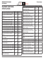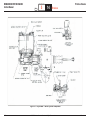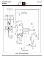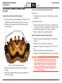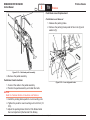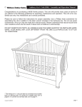
1
WORKHORSE CUSTOM CHASSIS
Service Manual
SECTION
5
W Series Chassis
PAGE
1
Brakes
2006
BRAKE SYSTEMS
WCC
© 2007 WorkhorseCustom Chassis — All Rights Reserved
W Seies
WORKHORSE CUSTOM CHASSIS
Service Manual
SECTION
TOC
5
TABLE OF CONTENTS
FASTENER TIGHTENING SPECIFICATIONS ...................6
BRAKE SYSTEM SPECIFICATIONS .................................7
BRAKE LATHE SPECIFICATIONS (AMMCO) ..................7
BRAKE LATHE SPECIFICATIONS (ACCU-TURN) ...........7
INTRODUCTION .................................................................8
Objectives Of This Section ..............................................8
Description and Operation ..............................................8
SERVICE BRAKE SYSTEM DESCRIPTION .....................8
Service Brake System Components ...............................9
Master Cylinder, Reservoir, and Fluid Level Sensor .......9
Hydraulic Brake Boosters ...............................................9
Master Cylinder .............................................................10
Basic Operation of Hydro-Max™ Booster Assembly
and Master Cylinder ......................................................12
Hydraulic Fluids ............................................................16
Brake Fluid Tubing, Hoses and Fittings ........................16
Booster Fluid Tubing, Hoses and Fittings .....................16
Booster Fluid Source ....................................................17
Pedal Stop and Proper Spring Load .............................17
Hydro-Max™ Brake System Diagnosis ........................18
Hydro-Boost™ Hydraulic Brake Booster .......................18
System Description .......................................................18
Master Cylinder .............................................................18
Reservoir and Cover .....................................................18
Power Steering Pump ...................................................18
Power Piston and Accumulator .....................................19
Brake Fluid and Brake Fluid Handling ..........................22
Substandard Or Contaminated Brake Fluid ..................22
Flushing the Brake Hydraulic System ...........................23
Normal Operation Noises ..............................................23
BRAKE SYSTEM TESTING .............................................24
External Conditions that Affect Brake Performance ......24
WCC
TOC
W Series Chassis
PAGE
2
Brakes
Tires ..............................................................................24
Vehicle Loading.............................................................24
Front Wheel Bearings ...................................................24
Front End Alignment .....................................................25
Brake Fluid Leaks .........................................................25
Brake Hose And Pipe Inspection ..................................25
DIAGNOSTICS AND TROUBLESHOOTING ...................26
Service Brake System ...................................................26
Master Cylinder Diagnosis ............................................26
Brake Hose and Pipe Diagnosis ...................................26
General Brake System Diagnosis .................................26
Excessive Pedal Effort ..................................................26
Pedal Pulsation (Brake Roughness or Chatter) ............27
Leaky Caliper ................................................................27
No Braking Effect or Excessive Pedal Travel ................27
Brake Noise Diagnosis – Chatter ..................................27
Brake Noise Diagnosis – Scraping ...............................28
Brake Noise Diagnosis – Groan ....................................28
Brake Noise Diagnosis – Rattle ....................................28
Brake Noise Diagnosis – Squeal ..................................28
BRAKE ROTORS .............................................................28
Hub and Rotor Assemblies ...........................................28
Brake Calipers and Pads ..............................................29
Brake Rotor Thickness Variation Check........................29
Brake Rotor Lateral Runout Check ...............................29
Brake Rotor Tolerance ..................................................30
Bosch Hydraulic Brake Diagnosis .................................30
Warning Light and Buzzer Do Not Shut Off .................31
Booster Backup Pump Runs Continuously ...................31
Booster Backup Pump Does Not Run...........................31
Brake Pedal Feels Spongy, Soft or Springy ..................31
Brake Pedal Feels Very Hard ........................................31
Potential Master Cylinder and Booster Leak Points .....31
Brake Drag ....................................................................32
© 2007 WorkhorseCustom Chassis — All Rights Reserved
W Series
WORKHORSE CUSTOM CHASSIS
Service Manual
SECTION
TOC
5
Antilock Brake System (ABS) Diagnostics ....................32
MAINTENANCE AND REPAIR .........................................32
Setup Procedures .........................................................32
Brake Actuation Linkage – Bell Crank Service..............33
Caliper Replacement (Brembo 52mM Caliper) .............34
Caliper Removal (Brembo 52mm Caliper) ....................34
Caliper Installation (Brembo 52mm Caliper) .................34
Caliper Replacement (Brembo 68mm Caliper) .............35
Caliper Removal (Brembo 68mm Caliper) ....................35
Caliper Installation (Brembo 68mm Caliper) .................35
Brake Caliper Replacement (Bosch ZOH-T Caliper) ....36
Brake Caliper Removal .................................................36
Brake Caliper Installation ..............................................37
Brake Caliper Replacement ..............................................
(Meritor Quadraulic Caliper) .........................................39
Brake Pad Replacement ...............................................39
Brake Pad Replacement (Brembo 52mm Caliper) ........39
Brake Pad Replacement (Brembo 68mm Caliper) ........43
Brake Pad Replacement (Bosch ZOH-T Caliper) .........44
Brake Pad Replacement
(Meritor Quadraulic Caliper) ..........................................45
Bleed Screw Replacement ............................................46
Seal and Dust Boot Replacement
(Brembo 52mm Caliper) ................................................46
Seal and Dust Boot Replacement
(Brembo 68mm Caliper) ................................................49
Seal and Dust Boot Replacement
(Bosch ZOH-T Caliper) .................................................50
Seal and Dust Boot Replacement
(Meritor Quadraulic Caliper) ..........................................51
Caliper Piston Replacement (Brembo 52mm Caliper) ..52
Caliper Piston Replacement (Brembo 68mm Caliper) ..55
Caliper Piston Replacement (Bosch ZOH-T Caliper) ....57
WCC
W Series Chassis
PAGE
3
Brakes
Caliper Piston Replacement
(Meritor Quadraulic Caliper) ..........................................58
Caliper Guide Pin and Dust Boot Replacement
(52mm Caliper) .............................................................60
Caliper Guide Pin and Dust Boot Replacement
(68mm Caliper) .............................................................60
Guide Pin and Boot Replacement
(Bosch ZOH-T Caliper) .................................................61
Caliper Mounting Bolt Replacement .............................62
Brake Rotor Replacement .............................................62
Brake Rotor Removal ....................................................62
Brake Rotor Installation .................................................62
Refinishing Brake Rotors ..............................................63
Burnishing the Rotors and Pads ...................................65
PARK BRAKE SYSTEM ..................................................65
Lever Actuated Park Brake System Components .........66
Automatic Apply Park Brake System Components .......66
J72 Park Brake Description ..........................................66
Actuator Assembly ........................................................70
PARK BRAKE SYSTEM DIAGNOSIS ..........................72
Park Brake Does Not Hold ............................................72
Park Brake Will Not Release .........................................73
COMPONENT REPLACEMENT (J72 Park Brake) .......74
Park Brake Assembly Replacement ..............................74
Park Brake Actuator Assembly Replacement ...............75
Park Brake System Diagnostics ....................................76
Park Brake System Check ............................................76
System Adjustment Procedures (Manual Apply
Park Brake) ...................................................................76
Park Brake Cable Adjustment .......................................76
Park Brake Service (Manual Apply Park Brake) ...........77
Park Brake Shoe Replacement.....................................77
Park Brake Pedal Replacement ....................................78
Park Brake Lever Replacement ....................................79
© 2007 WorkhorseCustom Chassis — All Rights Reserved
W Series
WORKHORSE CUSTOM CHASSIS
Service Manual
SECTION
TOC
5
Park Brake Pull Switch Replacement ...........................81
Park Brake Cable Replacement (Pedal Type) ..............81
Park Brake Cable Replacement (Lever Type) ..............82
Park Brake Drum Replacement ....................................82
Park Brake Drum Backing Plate Replacement .............84
Automatic Apply Park Brake Assembly Replacement ...84
Automatic Apply Park Brake Pump/Reservoir
Assembly Replacement ................................................85
ANTILOCK BRAKE SYSTEM (ABS) ..............................86
Antilock Brake System (ABS) Components ..................87
ABS Electronic Control Unit (ECU) ...............................87
Modulator Assembly ......................................................87
Wheel Speed Sensors ..................................................88
Sensor Spring Clip ........................................................88
Tooth Wheel ..................................................................88
ABS Indicator Lamp ......................................................89
ABS Diagnostic Procedures ..........................................89
System Diagnostics ......................................................89
Valve, Pump and Retarder Relay Activation .................91
Retarder Relay Activation on WABCO Antilock
Brake System ................................................................91
Reset Memorized ..........................................................92
Fault Information Screen ...............................................93
ABS Indicator Lamp Activation......................................93
Standard System Testing .............................................94
System Requirements and Component Tests ...............94
Standard Component Testing .......................................96
Component Removal and Installation ........................100
Sensors .......................................................................100
Wheel Speed Sensor Replacement — Front Axle ......100
Wheel Speed Sensor Replacement — Rear Axle.......101
Modulator Assembly ....................................................102
ABS Brake Bleeding Procedures ................................103
General .......................................................................103
WCC
W Series Chassis
PAGE
4
Brakes
Pressure Fill and Bleed ...............................................104
System Requirements .................................................107
TOOLBOX™ Start-up .................................................108
Hydraulic ABS .............................................................109
Component Tests ........................................................ 110
MERITOR WABCO FAULT CODES ...............................113
DIAGNOSTIC TROUBLE CODES..................................124
DTC P0608 .................................................................124
DTC P0609 .................................................................127
© 2007 WorkhorseCustom Chassis — All Rights Reserved
W Series
WORKHORSE CUSTOM CHASSIS
Service Manual
SECTION
TOC
5
W Series Chassis
PAGE
5
Brakes
THIS PAGE LEFT BLANK INTENTIONALLY
WCC
© 2007 WorkhorseCustom Chassis — All Rights Reserved
W Series
WORKHORSE CUSTOM CHASSIS
Service Manual
SECTION
5
TOC
FASTENER TIGHTENING
SPECIFICATIONS
Description
W Series Chassis
PAGE
6
Brakes
Description
English
Metric
English
Metric
Caliper to caliper mounting bracket bolts
(Brembo 68mm Caliper)
115 lb ft
84 N·m
Caliper to caliper mounting bracket bolts
(Bosch ZOH-T Caliper)
93-107
lb ft
126-145
N·m
Caliper to caliper mounting bracket bolts
(Meritor Quadraulic Caliper)
225 lb ft
305 N·m
Caliper mounting bracket to steering
knuckle bolts (Brembo 52mm Caliper)
127 lb ft
172 N·m
Caliper mounting bracket to steering
knuckle bolts (Brembo 68mm Caliper)
159 lb ft
215 N·m
Caliper mounting bracket to steering
knuckle bolts (Bosch ZOH-T Caliper)
206 lb ft
280 N·m
Caliper mounting bracket to steering
knuckle bolts (Meritor Quadraulic Caliper
– 5/8-inch, 18 bolt)
225 lb ft
305 N·m
Caliper mounting bracket to steering
knuckle bolts (Meritor Quadraulic Caliper
– 9/16-inch, 18 bolt)
150 lb ft
203 N·m
ABS sensor bolt (Bosch ZOH-T Caliper)
12-16 lb ft
17-21 N·m
ABS sensor bolt (Meritor Quadraulic
Caliper)
124 lb in
14 N·m
Anchor Plate Bolt Plug (Bosch ZOH-T
Caliper)
16-27 lb ft
22-37 N·m
Banjo bolt (Meritor Quadraulic Caliper)
35 lb ft
47 N·m
Bleed screw (Brembo 52mm Caliper)
124 lb in
14 N·m
Bleed screw (Brembo 68mm Caliper)
177 lb in
20 N·m
Bleed screw (Bosch ZOH-T Caliper)
150 lb in
17 N·m
Bleed screw (Meritor Quadraulic Caliper)
97 lb in
11 N·m
Brake hose fitting (Brembo 52mm Caliper)
164 lb in
18.5 N·m
Brake hose fitting (Brembo 68mm Caliper)
212 lb in
24 N·m
Brake hose fitting (Bosch ZOH-T Caliper)
168 lb in
19 N·m
Brake hose fitting (Meritor Quadraulic
Caliper)
350 lb ft
475 N·m
124 lb in
14 N·m
Brake hose hold down clamp bolt (Bosch
ZOH-T Caliper)
Cross over tube nuts (Meritor Quadraulic
Caliper)
13 lb ft
17 N·m
195 lb in
22 N·m
Brake hose hold down clamp bolt (Meritor
Quadraulic Caliper)
Lining rail Covers (Meritor Quadraulic
Caliper)
124 lb in
14 N·m
Rotor to hub bolts (Brembo 52mm Caliper)
140 lb ft
190 N·m
Brake pad retainer spring bolt (Meritor
Quadraulic Caliper)
Rotor to hub bolts (Brembo 68mm Caliper)
130 lb ft
176 N·m
30 lb ft
41 N·m
112 lb ft
152 N·m
Brake shield bolts (Brembo 52mm Caliper)
19 lb ft
25 N·m
Rotor to hub bolts (Bosch ZOH-T Caliper,
9/16-inch OD – 10 bolt pattern)
Brake shield bolts (Brembo 68mm Caliper)
19 lb ft
25 N·m
189 lb ft
256 N·m
Brake shield bolts ((Bosch ZOH-T Caliper)
19 lb ft
26 N·m
Rotor to hub bolts (Bosch ZOH-T Caliper,
9/16-inch OD – 10 bolt pattern)
Brake shield bolts (Meritor Quadraulic
Caliper)
lb ft
N·m
Rotor to hub bolts (Meritor Quadraulic
Caliper – 5/8-inch, 5 bolt)
110 lb ft
149 N·m
Caliper to caliper mounting bracket bolts
(Brembo 52mm Caliper)
25 lb ft
34 N·m
Rotor to hub bolts (Meritor Quadraulic
Caliper – 9/16-inch, 18 bolt, with lock nuts)
90 lb ft
122 N·m
WCC
© 2007 WorkhorseCustom Chassis — All Rights Reserved
W Series
WORKHORSE CUSTOM CHASSIS
Service Manual
Description
SECTION
5
TOC
English
Metric
Rotor to hub bolts (Meritor Quadraulic
Caliper – 9/16-inch, 18 bolt, with plain nuts)
150 lb ft
203 N·m
Splash Shield (Bosch ZOH-T Caliper)
12-16 lb ft
17-21 N·m
Support key bolt (Bosch ZOH-T Caliper)
15 lb ft
20 N·m
BRAKE SYSTEM SPECIFICATIONS
Description
English
Metric
Brake Pad minimum thickness above
metal – discard (Brembo 52mm Caliper)
.125 in
3.175mm
Brake Pad minimum thickness above
metal – discard (Brembo 68mm Caliper)
.125 in
3.175mm
Brake Pad minimum thickness above
metal – discard (Bosch ZOH-T Caliper)
.125 in
3.175mm
Brake Pad minimum thickness above
metal – discard (Meritor Quadraulic
Caliper)
.125 in
3.175mm
Brake fluid
DOT 3
Rotor diameter (Brembo 52mm Caliper)
12.25 in 307mm
Rotor diameter (Brembo 68mm Caliper)
12.88 in 322mm
Rotor diameter (Bosch ZOH-T Caliper)
14.28 in
Rotor diameter (Meritor Quadraulic
Caliper)
15.38 in 390.7mm
357mm
Rotor thickness – discard (Brembo 52mm Refer to Marking on
Caliper)
Rotor
Rotor thickness – discard (Brembo
68mm Caliper)
Refer to Marking on
Rotor
Rotor thickness – discard (Bosch ZOH-T
Caliper)
Refer to Marking on
Rotor
Rotor thickness – discard (Meritor
Quadraulic Caliper)
Refer to Marking on
Rotor
WCC
W Series Chassis
PAGE
7
Brakes
BRAKE LATHE SPECIFICATIONS
(AMMCO)
Data
Rough Cut
Finish Cut
Spindle Speed
150 RPM
150 RPM
Depth of Cut
(per side)
0.127 mm
(0.005 in)
0.051 mm
(0.002 in)
Total Cross Feed
(per revolution)
0.152 – 0.254 mm
(0.006 – 0.01 in)
0.051 mm max.
(0.002 in)
Vibration
Dampener
Yes
Yes
Swirl Pattern
120 Grit
No
Yes
BRAKE LATHE SPECIFICATIONS
(ACCU-TURN)
Data
Cut Information
Spindle Speed
150 RPM
Tool Cross Feed
(per revolution)
0.076 mm (0.003 in)
Tool Bit Nose Radius
0.396 mm (0.003 in)
Vibration Dampener
Yes
Swirl Pattern 120 Grit
Yes
© 2007 WorkhorseCustom Chassis — All Rights Reserved
W Series
WORKHORSE CUSTOM CHASSIS
Service Manual
SECTION
TOC
5
INTRODUCTION
This section is intended to provide information regarding
the hydraulic brake system components. This is specific
to the W-Series Workhorse Chassis.
Explanations for most components will include purpose,
function, operation, and location. Guidance for proper
and safe disassembly, inspection, repair, and assembly
are provided.
DESCRIPTION AND OPERATION
There are three brake systems on a Workhorse motor
home chassis:
• Antilock Brake System (ABS)
• Park Brake System
WCC
8
Brakes
SERVICE BRAKE SYSTEM
DESCRIPTION
OBJECTIVES OF THIS SECTION
• Service Brake System
W Series Chassis
PAGE
The service brakes are the primary brake system for
the chassis. The system uses hydraulic pressure from a
foot-pedal operated master cylinder to actuate cylinders
that apply the brake pads to the braking surfaces on the
brake rotors. The amount of hydraulic pressure in the
system (applied by the driver) determines how much
pressure is applied to the brake pads on the brake
rotors.
Hydraulic pressure created by the master cylinder
operation is transmitted through brake lines and hoses
to the wheel cylinders and calipers. The hydraulic
pressure forces the pistons in the wheel cylinders and/or
calipers outward, causing the brakes to be applied.
Braking action occurs as a result of friction between
the brake lining and the metal surface of the rotor disc.
Brake power is generated when the friction material
that has been displaced on the rotor bonds itself to the
friction material on the pads. After bonding has occurred,
the rotation of the wheel will cause the bond to break
apart or shear. This cycle of bonding and shearing is
how the brakes stop the vehicle.
© 2007 WorkhorseCustom Chassis — All Rights Reserved
W Series
WORKHORSE CUSTOM CHASSIS
Service Manual
SECTION
TOC
5
SERVICE BRAKE SYSTEM COMPONENTS
The hydraulic brake system is made up of the following
components:
• Master cylinder, reservoir, and fluid level sensor
• Hydraulic brake booster
• Brake rotors
• Brake calipers and pads
• Brake lines and hoses
Master Cylinder, Reservoir, and Fluid Level Sensor
The W Series chassis uses a Bosch aluminum master
cylinder and plastic brake fluid reservoir. The brake fluid
reservoir is equipped with a fluid level sensor to alert the
driver when the brake fluid level is low.
Hydraulic Brake Boosters
The W Series chassis use two different styles of
hydraulic brake boosters. Refer to the following table for
chassis specific applications.
Chassis Series
W16 / W18
W20 / W22 / W24 / W25
W42
W52
WCC
Booster Design
Bosch Hydro-Boost™
Bosch Hydro-Max™
Bosch Hydro-Boost™
Bosch Hydro-Max™
W Series Chassis
PAGE
9
Brakes
Hydro-Max™ Hydraulic Brake Booster
The Hydro-Max™ system is utilized on all W20/W22/
W24/W25 Series chassis. The hydraulic pressure used
to operate the power brake booster is normally supplied
by the power steering pump. If fluid flow is not available
form the pump, the booster’s electric backup pump
operates to supply the required braking force.
Hydraulic pressure is monitored when the brake is
applied. If hydraulic pressure is not available from the
power steering pump (engine is off), the backup pump is
activated to provide hydraulic pressure for normal brake
operation.
During normal system operation, fluid flow from the
power steering pump enters the inlet port of the HydroMax™ booster, flows through the power piston, around
the throttle valve and through the flow switch, exiting
through the outlet port. (Refer to the illustration on the
following page.)
Force applied to the brake pedal by the vehicle operator
is multiplied by the lever ratio of the pedal mechanism
to move the pedal rod of the booster. This movement
closes the throttle valve, which restricts flow. This
restriction of flow, which results in a pressure increase
acting on the power piston, applies an amplified force
to the master cylinder primary piston. A reaction piston,
inside the power piston subassembly, provides the
driver “pedal feel” during an application of the brake
pedal. Fluid flow through the flow switch opens the
backup pump electrical circuit during normal operation.
© 2007 WorkhorseCustom Chassis — All Rights Reserved
W Series
WORKHORSE CUSTOM CHASSIS
Service Manual
SECTION
TOC
5
A separate check valve in the backup pump prevents
back-flow through the pump during normal power
applications.
In the event normal flow from the power source is
interrupted, the backup pump provides the power at a
reduced rate for stopping. Upon flow interruption, the
integral flow switch closes, energizing a relay, providing
electrical power to the backup pump. During backup
operation, the pump re-circulates fluid within the booster
assembly with pressure built on demand via the throttle
valve. Fluid is retained within the booster by the inlet
port check valve.
W Series Chassis
PAGE
10
Brakes
MASTER CYLINDER
In the released position, (refer to the illustration on
the following page.) actuators of both the primary
and secondary pistons are in with their respective
compensating valve stems, which project into the
cylinder bore. This contact tilts the valves to an open
position, which allows hydraulic fluid in the reservoir
sections to communicate with the primary and
secondary pressure chambers. Each pressure chamber
has a piston/actuator subassembly containing a
preloaded (caged) spring and return spring.
Initial forward travel of the primary piston moves the
primary actuator away from its compensating valve,
permitting the valve to seat. Closure of this valve shuts
off the passage between the primary pressure chamber
and the reservoir section serving the primary chamber.
Figure 5-1 — Hydro-Max™ Booster and Master Cylinder
WCC
© 2007 WorkhorseCustom Chassis — All Rights Reserved
W Series
WORKHORSE CUSTOM CHASSIS
Service Manual
SECTION
TOC
5
W Series Chassis
PAGE
11
Brakes
Figure 5-2 — Hydro-Max™ Booster Components
WCC
© 2007 WorkhorseCustom Chassis — All Rights Reserved
W Series
WORKHORSE CUSTOM CHASSIS
Service Manual
SECTION
TOC
5
Further movement of the primary piston creates
pressure in the primary pressure chamber, causing
the secondary piston and actuator to move. As the
secondary piston and actuator move, the secondary
compensating valve closes, shutting off the passage
between the secondary pressure chamber and the
reservoir section serving the secondary chamber.
Additional movement of the primary piston causes both
chambers to build pressure.
When the load on the primary piston is removed, fluid
pressure in each chamber, combined with return spring
force, causes the primary and secondary pistons to
return to their initial released positions. Each actuator
opens its respective compensating valve, reopening the
passage between the individual reservoir sections and
its associated pressure chamber.
Should the rate of release be great enough to cause a
partial vacuum in the chamber, the compensating valve
will open to allow replenishment of fluid into the cylinder
bore.
Any excess fluid remaining at the end of the stroke
due to “pumping” and/or volume change due to
temperature fluctuation is released to the reservoir as
the compensating valves open.
The primary circuit is separated from the secondary
hydraulic circuit. Hydraulic leakage in one circuit does
not affect the function of the other circuit.
WCC
W Series Chassis
PAGE
12
Brakes
A fluid level indicator switch is available. It illuminates a
light on the dash panel to warn of low brake fluid level in
the master cylinder reservoir. A low fluid level can result
from brake shoe lining wear, or it can occur if there is an
external leak in the vehicle brake system.
A differential pressure switch is available. It illuminates a
light on the dash panel to warn when there is a pressure
differential between the primary and secondary brake
circuits caused by a leak in one circuit. This may occur
when one circuit leaks or is improperly bled.
A remote reservoir application is available where
under-the-hood space constraints prohibit the use of a
conventional booster and master cylinder assembly. In
a remote application, the master cylinder reservoir is
mounted separately from the master cylinder.
Basic Operation of Hydro-Max™ Booster Assembly and
Master Cylinder
(Refer to the illustration on the following page to identify
the following electrical components of the booster and
master cylinder.)
Backup Pump: The Hydro-Max™ hydraulic booster has
a backup pump which will provide hydraulic boost at a
reduced rate if the normal source of fluid is interrupted.
The signal for operation of the backup pump comes from
the flow switch. If normal flow is interrupted, the flow
switch will close and activate the relay, which will turn on
the backup pump.
© 2007 WorkhorseCustom Chassis — All Rights Reserved
W Series
WORKHORSE CUSTOM CHASSIS
Service Manual
SECTION
TOC
5
The 12-volt backup pump can draw a steady state
maximum of 55 amps at a power steering fluid
temperature of 100 degrees F. The Hydro-Max™Master
Cylinder and Booster Components
Relay: The function of the relay is to provide current to
the backup pump when triggered by the flow switch.
Flow Switch: The function of the flow switch is to
activate the relay when normal hydraulic power source
fluid flow is interrupted, turning on the backup pump.
The flow switch has two terminals (A and B). A is
positive. B is connected to the booster housing and is
used as an optional harness ground. The flow switch
itself is grounded through the booster housing.
W Series Chassis
PAGE
13
Brakes
Differential Pressure Switch: The differential pressure
switch reacts to a loss of master cylinder hydraulic
pressure in either side of the split hydraulic system and
can illuminate a warning light at the instrument panel.
When pressure is lost in either the primary or secondary
circuit of the master cylinder, the switch closes. The
electrical switch will remain closed until the malfunction
is corrected.
When both systems develop normal pressure, the
switch will return to center and open the electrical switch
circuit. The switch has two tabs on a common terminal
(positive) and is grounded through the master cylinder.
Fluid Level Switch: When the fluid reaches a
predetermined level (low fluid level), the switch closes
and can illuminate a warning light at the instrument
panel. The switch has two terminals, positive and
negative, which are interchangeable.
Chassis Ground: The booster and master cylinder
assembly must be provided with a ground path that will
carry the maximum current of the backup pump.
WCC
© 2007 WorkhorseCustom Chassis — All Rights Reserved
W Series
WORKHORSE CUSTOM CHASSIS
Service Manual
SECTION
TOC
5
W Series Chassis
PAGE
14
Brakes
Figure 5-3 — Hydro-Max™ Master Cylinder Components
WCC
© 2007 WorkhorseCustom Chassis — All Rights Reserved
W Series
WORKHORSE CUSTOM CHASSIS
Service Manual
SECTION
TOC
5
W Series Chassis
PAGE
15
Brakes
Figure 5-4 — Hydro-Max™ Electrical Components
WCC
© 2007 WorkhorseCustom Chassis — All Rights Reserved
W Series
WORKHORSE CUSTOM CHASSIS
Service Manual
SECTION
TOC
5
HYDRAULIC FLUIDS
The Hydro-Max™ booster uses power steering fluid as
the medium of transmitting power.
The master cylinder uses DOT 3 brake fluid per SAE
J1703, unless otherwise specified on the top of the
reservoir. Service maintenance of motor vehicle brake
fluid in motor vehicle brake actuating systems is covered
in SAE J1707 information report.
WARNING
The booster and the master cylinder use two
(2) distinctly different incompatible hydraulic
fluids. They must not be mixed. Using the
incorrect fluid will permanently damage the
seals and can cause the brakes to malfunction.
BRAKE FLUID TUBING, HOSES AND FITTINGS
W Series Chassis
PAGE
16
Brakes
are recommended for consideration as a minimum
requirement when outfitting a vehicle with brake fluid
tubing, hoses and fittings. The hoses should conform
to SAE J1401 Hydraulic Brake Hose - Automotive. The
tubing should conform to SAE J1047 Tubing - Motor
Vehicle Hydraulic Brake System. The fittings should
conform to SAE J516a - Hydraulic Hose Fittings, or SAE
J512 - Automotive Tube Fittings.
NOTICE
Contact the Workhorse for specific requirements for
individual applications.
Booster Fluid Tubing, Hoses and Fittings
The pressure line that supplies fluid to the booster
must be a 1/2” diameter flexible or rigid pressure line
conforming to SAE J188 and typically designed to run
from the steering gear to the Hydro- Max™ inlet. The
Hydro-Max™ inlet port utilizes a tube “O” arrangement.
Brake fluid lines (tubing and flexible hose) transmit
fluid under pressure between the master cylinder and
the brakes. The hoses are the flexible links between
wheels or axles and the frame or body. The hoses
must withstand fluid pressure with minimal expansion
and must be free to flex without damage during normal
suspension deflection and wheel turns. The following
SAE specifications, or their successors if appropriate,
Figure 5-5 — Tube “O” Fitting and O-ring Seal
WCC
© 2007 WorkhorseCustom Chassis — All Rights Reserved
W Series
WORKHORSE CUSTOM CHASSIS
Service Manual
SECTION
TOC
5
W Series Chassis
PAGE
17
Brakes
Booster Fluid Source
Figure 5-6 — Tube Flare Configuration
The booster is designed to perform in a flow range of 3.2
to 5.0 gpm. Flow rate through the booster can impact
vehicle stopping distance; therefore, the technician
may be required to determine the minimum flow rate if
poor brake performance is indicated. Flow rates below
3.2 gpm can cause slower response times when the
booster is applied. Flow rates higher than 5.0 gpm may
contribute to the booster self-applying, which will cause
brake drag or fluid overheating.
The power steering pump must be capable of supplying
1,000 psi to the booster plus any additional pressure
required by other devices in the system such as a power
steering gear.
Pedal Stop and Proper Spring Load
Figure 5-7 —Outlet Port
The pedal stop must be adjusted such that when the
brake pedal is fully released, there is no load on the
grommet that retains the pedal rod to the Hydro-Max™
booster. When the brake pedal is fully released, the
spring load must not be greater than that required to
support the pedal weight.
The reason for a properly adjusted pedal stop and for
the limitation on spring load is to prevent the spring
from pulling on the grommet within the Hydro-Max™
booster and damaging the grommet. The grommet is not
designed to be loaded in this manner.
WCC
© 2007 WorkhorseCustom Chassis — All Rights Reserved
W Series
WORKHORSE CUSTOM CHASSIS
Service Manual
SECTION
TOC
5
NOTICE
Any adjustment of the brake switch and backup pump
must not compromise the adjustment of the pedal stop.
Hydro-Max™ Brake System Diagnosis
Refer to the following tables when diagnosing problems
with the Hydro-Max™ master cylinder and booster.
HYDRO-BOOST™ HYDRAULIC BRAKE BOOSTER
System Description
The hydraulic booster provides power assist using fluid
pressure from the power steering pump.
The Hydro-Boost™ system uses hydraulic pressure
from the power steering pump to operate the master
cylinder. The Hydro-Boost™ unit is located between
the master cylinder and the brake pedal. The brake
pedal is connected to a valve inside the Hydro-Boost™
unit and allows the driver to control brake application.
The operation of the Hydro-Boost™ unit is similar to
the vacuum boost unit except that the Hydro-Boost™
unit uses a hydraulic piston and a hydraulic pressure
from the power steering pump to create the force to the
master cylinder.
WCC
W Series Chassis
PAGE
18
Brakes
Master Cylinder
The master cylinder is an aluminum unit. The system
uses a conventional front-to-rear brake split. The primary
piston provides fluid pressure to the front brakes. The
secondary piston provides fluid pressure to the rear
brakes. If pressure is lost in either system, the remaining
system is capable of stopping the vehicle.
Reservoir and Cover
The reservoir is made of plastic. Two clips snap the cap
onto the reservoir. A diaphragm between the cover and
the reservoir keeps contaminants out of the brake fluid.
Keep the master cylinder reservoir properly filled with
brake fluid. This ensures adequate reserve brake fluid
and prevents air from entering the hydraulic system. Do
not over fill the reservoir. The brake fluid absorbs heat
from the brakes, and expands. An over-filled reservoir
cannot allow fluid expansion.
Power Steering Pump
The power steering pump supplies the Hydro-Boost™
unit with hydraulic pressure the same way the engine
manifold vacuum supplies power to the vacuum boost
system. The pump, which is driven by the engine, also
supplies hydraulic pressure to the power steering gear.
© 2007 WorkhorseCustom Chassis — All Rights Reserved
W Series
WORKHORSE CUSTOM CHASSIS
Service Manual
SECTION
TOC
5
Power Piston and Accumulator
The Hydro-Boost ™unit contains a valve, a power
piston and an accumulator. When the valve is moved by
the brake pedal linkage, hydraulic pressure is applied
to the power piston. The pressure forces the power
piston to move forward, toward the master cylinder. The
movement of the piston causes the output rod to operate
the master cylinder. When the brake pedal is pushed
harder, more hydraulic pressure is applied to the piston
and the brakes are applied harder.
WCC
W Series Chassis
PAGE
19
Brakes
The accumulator stores hydraulic fluid under pressure.
If the power steering pump fails, this reserve pressure
allows at least two brake applications before complete
loss of power assist. The accumulator serves the same
function as the vacuum reservoir in the vacuum boost
system. The difference is that an accumulator stores
hydraulic pressure and a vacuum reservoir stores
vacuum pressure. The accumulator has a piston which
compresses nitrogen gas as the reserve chamber fills.
CAUTION:
High pressure can exist in the accumulator
circuit with the engine turned off. This can be
extremely dangerous!
© 2007 WorkhorseCustom Chassis — All Rights Reserved
W Series
WORKHORSE CUSTOM CHASSIS
Service Manual
SECTION
TOC
5
W Series Chassis
PAGE
20
Brakes
Figure 5-8 — Hydro-Boost System Design
Braking Position
When the brake pedal is pressed, the pushrod moves
the ratio lever which starts the movement of the spool
valve. This closes the fluid return port to the pump from
the booster pressure chamber and allows hydraulic fluid
to enter the booster pressure chamber.
WCC
The hydraulic pressure in the booster pressure chamber
forces the piston forward, actuating the master cylinder
piston.
As the spool valve moves along its bore, the lands
prevent fluid flow from the power steering pump to the
steering gear. This causes the power steering pump to
increase fluid pressure to maintain the same flow rate.
© 2007 WorkhorseCustom Chassis — All Rights Reserved
W Series
WORKHORSE CUSTOM CHASSIS
Service Manual
SECTION
TOC
5
W Series Chassis
PAGE
21
Brakes
Figure 5-9 — Hydro-Boost™ Internal Components
If pressure is required for power steering during braking,
the power steering pump increases the pressure. The
spool valve shifts to an open position and allows more
fluid to flow to the power steering gear. The system
stores enough fluid under pressure for brake application
if fluid flow from the power steering pump is not
available. The brakes can also be applied manually if the
reserve system is depleted.
WCC
Released Position – No Braking
When the brake pedal is released, the spool valve return
spring holds the spool valve open. In the open position
the spool valve channels hydraulic fluid from the power
steering pump directly to the power steering gear, and
lands on the spool valve which block the fluid from
entering the boost pressure chamber.
© 2007 WorkhorseCustom Chassis — All Rights Reserved
W Series
WORKHORSE CUSTOM CHASSIS
Service Manual
SECTION
TOC
5
NOTICE
No internal components of the Hydro-Boost™ booster
are serviced separately. If an internal failure occurs, the
booster assembly must be replaced.
BRAKE FLUID AND BRAKE FLUID HANDLING
CAUTION:
Brake fluid may be irritating to the skin or
eyes. In case of contact, take the following
actions:
Eye contact-rinse eyes thoroughly with water.
Skin contact-wash skin with soap and water.
NOTICE
Brake fluid will damage electrical connections and
painted surfaces. Use shop cloths, suitable containers,
and fender covers to prevent brake fluid from contacting these areas. Always re-seal and wipe off brake fluid
containers to prevent spills.
Use Brake Fluid P/N 1052535, or an equivalent DOT-3
motor vehicle brake fluid. Always store brake fluid in a
closed, sealed container. Never use previously opened,
improperly sealed containers of stored brake fluid.
Always use new brake fluid, or fluid from a properly
sealed container.
WCC
W Series Chassis
PAGE
22
Brakes
Re-seal brake fluid containers immediately after use.
Brake fluid left in open or improperly sealed containers
will absorb moisture. Moisture can lower the brake fluid
boiling point, causing the following problems:
• Brake system contamination.
• Corrosion.
• Deterioration of rubber components.
Substandard Or Contaminated Brake Fluid
NOTICE
Power steering fluid and brake fluid cannot be mixed.
If brake seals contact power steering fluid or steering
seals contact brake fluid, seal damage will result.
Use the correct fluids. The master cylinder and brake
system use brake fluid. The hydraulic booster system
uses power steering fluid.
If the brake fluid contains improper fluid, water, or other
contaminants, the brake fluid may boil or corrode rubber
components in the hydraulic brake system.
Evidence of rubber deterioration occurs in the following
areas:
• Swollen master cylinder piston seals
• Swelling of the wheel cylinder boots
• Swelling of caliper boots
• Swelling of the master cylinder reservoir diaphragm
© 2007 WorkhorseCustom Chassis — All Rights Reserved
W Series
WORKHORSE CUSTOM CHASSIS
Service Manual
SECTION
TOC
5
If you find rubber deterioration, replace all rubber parts
in the brake system, including the hoses. Check for
brake fluid on the brake linings. Replace brake linings
that are contaminated with brake fluid.
If the brake fluid is contaminated and the master cylinder
piston seals are good, check for leaks and excessive
heat conditions. If no leaks or excessive heat conditions
are found, perform the following procedure:
1.
2.
3.
4.
Drain the brake system.
Flush the system.
Refill the system.
Bleed the system.
FLUSHING THE BRAKE HYDRAULIC SYSTEM
Flushing the brake hydraulic system involves running
new brake fluid through the system and out the open
bleeder valves, until the fluid runs clear. Use Brake Fluid
P/N 1052535, or an equivalent DOT-3 motor vehicle
brake fluid.
W Series Chassis
PAGE
23
Brakes
NORMAL OPERATION NOISES
Properly operating Hydro-Max™ and Hydro-Boost™
hydraulic brake boosters may produce certain noises.
These noises occur, for the most part when the brake
pedal is manipulated in a manner not associated with
everyday driving habits. The general categories of
normal operating noises are (1) hissing noises and (2)
clunk/clatter noises.
The boosters may emit normal hissing noises when
above-normal brake pedal efforts are applied (40 lbs.
and up). The hiss sounds particularly noticeable with the
vehicle motionless and will increase in intensity as pedal
pressure increases above 40 lbs. and system operating
temperature increases. Loud hissing sounds at or below
normal (20 to 25 lbs.) pedal effort warrants investigation.
Clunk, clatter or clicking noises will be heard when the
brake pedal is quickly released from hard (50 to 100
lbs.) pedal efforts.
Flush the brake hydraulic system for the following
reasons:
• When new hydraulic brake parts are installed
• When contamination may be present. Flushing is the only
way to clean contaminated fluid out of the system
• When you do not know the grade of brake fluid in the
brake system.
• When mineral oil is present in the brake fluid
WCC
© 2007 WorkhorseCustom Chassis — All Rights Reserved
W Series
WORKHORSE CUSTOM CHASSIS
Service Manual
SECTION
TOC
5
BRAKE SYSTEM TESTING
IMPORTANT:
If the vehicle pulls to one side during braking, do not
assume the cause is a brake system malfunction.
Ensure that the front end alignment is correct before
diagnosing the brake system.
Test the brakes at different speeds with light pedal
pressure and with heavy pedal pressure. Avoid locking
the wheels. Avoid sliding the tires on the roadway.
Locked wheels and sliding tires do not show brake
efficiency. A locked wheel and a sliding tire reduce the
tire friction on the roadway. Heavily braked, turning
wheels will stop the vehicle in less distance.
Test the brakes on a dry, clean, reasonably smooth
and level roadway. You cannot accurately test brake
performance without these conditions. The tires will not
grip the roadway equally if the roadway is wet or greasy
or covered with loose dirt. A crowned roadway causes
the weight of the vehicle to shift toward one side. The
wheels bounce on a rough road way.
The following conditions also affect brake performance:
Tires with unequal contact and unequal grip on the road
will cause unequal braking.
• The tires must be equally inflated.
• The tread pattern of the right tires and the left tires must
be about equal.
W Series Chassis
PAGE
24
Brakes
When the vehicle is loaded unequally, the most heavily
loaded wheels require more braking power than the
other wheels. Loose front wheel bearings may cause the
following:
• Brake rotor tilt
• Spotty contact with the brake linings
• Erratic braking action
The brakes will pull the vehicle to one side if the front
suspension is not aligned correctly. This will be very
noticeable if the caster and the camber are not within
specifications.
EXTERNAL CONDITIONS THAT AFFECT BRAKE
PERFORMANCE
Tires
Tires with unequal contact and grip on the road cause
unequal braking. Make sure the inflation and tread
pattern of the right and left tires is about equal.
Vehicle Loading
When the vehicle has unequal loading, the most heavily
loaded wheels require more braking force than the
others.
Front Wheel Bearings
Loose front wheel bearings permit the rotor to tilt and
to have poor contact with the linings. This may cause
erratic braking.
WCC
© 2007 WorkhorseCustom Chassis — All Rights Reserved
W Series
WORKHORSE CUSTOM CHASSIS
Service Manual
SECTION
TOC
5
Front End Alignment
Misalignment of the front end, particularly camber and
caster, causes the brakes to pull to one side.
BRAKE FLUID LEAKS
Use the following procedure in order to test for brake
problems that may be caused by fluid leaks:
1. Start the engine and run the engine at idle speed.
2. Shift the transmission into neutral.
3. Maintain constant foot pressure on the brake pedal. If the
pedal slowly sinks to the floor, the hydraulic system may
have internal leakage, external leakage or improperly
adjusted components.
4. Check the fluid level of the master cylinder. A slightly low
fluid level in either reservoir can result from normal wear of
the front brake lining. An abnormally low fluid level indicates
a leak in the hydraulic system.
5. Perform a visual inspection of the hydraulic system.
WCC
W Series Chassis
PAGE
25
Brakes
If you find a leaking component, refer to the applicable
replacement or overhaul procedure.
If you find no external leaks, internal leakage may be
the cause. The master cylinder serviced as an assembly
and must be replaced if a leak is present..
Brake Hose And Pipe Inspection
Inspect the brake hoses and the brake pipes at least two
times a year for the following conditions:
• Chafing of the outer cover
• Cracks
• Road damage
• Check that all hose and pipe mounting hardware Replace
any leaky or damaged hose or pipe. Repair any insecure
mounting hardware.
© 2007 WorkhorseCustom Chassis — All Rights Reserved
W Series
WORKHORSE CUSTOM CHASSIS
Service Manual
SECTION
TOC
5
DIAGNOSTICS AND
TROUBLESHOOTING
26
Brakes
Brake Hose and Pipe Diagnosis
SERVICE BRAKE SYSTEM
Master Cylinder Diagnosis
These tests will not find all master cylinder malfunctions.
If you cannot find the cause with these tests, refer to
Brake System Diagnosis.
Visual Inspection
Check for a cracked casting or brake fluid leaks around the master
cylinder.
A leak will have at least one drop of fluid. A damp condition is normal.
Check the pedal linkage for binding and for incorrect pushrod length.
Disassemble the master cylinder if no brake pedal binding or improper
brake pedal travel is found. Refer to Master Cylinder Overhaul.
Check the master cylinder for swollen or elongated primary piston
seals.
If you find swollen seals, refer to Brake Fluid and Brake Fluid
Handling.
WCC
W Series Chassis
PAGE
Inspect all pipes, hoses, and fittings for leaks at regular
intervals. The fittings must be tight. All clips, clamps, and
unions supporting the pipes and hoses must be securely
in place. Ensure that all hoses and tubes do not contact
parts of the vehicle. Wipe clean any area suspected of
leaking. Leaking fluid will then be easily seen. If a leak
is found, tighten, repair, or replace nearby fittings and
bolts.
GENERAL BRAKE SYSTEM DIAGNOSIS
Excessive Pedal Effort
Condition
Suggested Correction
Pads worn below minimum
thickness specification.
Replace the pads.
Faded, overheated condition,
glazed pads, “blued” or heatchecked rotors.
Replace the affected rotor and/or
reface the pads, if sufficient brake
lining remains.
Grease, oil, and/or brake fluid
on the brake linings.
Replace both sets of pads on the
affected axle.
Seized or frozen pistons.
Disassemble the calipers to free the
pistons, or replace the caliper.
© 2007 WorkhorseCustom Chassis — All Rights Reserved
W Series
WORKHORSE CUSTOM CHASSIS
Service Manual
SECTION
TOC
5
Pedal Pulsation (Brake Roughness or Chatter)
Condition
Suggested Correction
W Series Chassis
PAGE
27
Brakes
No Braking Effect or Excessive Pedal Travel
Condition
Suggested Correction
Excessive lateral runout of
brake rotor.
Install a new rotor if runout exceeds
the maximum specification.
Reservoir fluid level low
Excessive out-of-parallelism
of brake rotor.
Check the parallelism (rotor
thickness variation) with a
micrometer.
If the rotor thickness variation is
within specification, resurface the
rotor.
If the rotor thickness is beyond
specification, replace the rotor.
Check for causes of fluid leak, repair
as required and refill the reservoir.
Bleed system as needed.
Air in the hydraulic system
Bleed the system.
Bleeder screw loose or open
Bleed the system and tighten the
bleeder screw.
Caliper piston seal damaged
Disassemble the caliper and replace
the piston seals. Replace piston if
damaged.
Excessive rotor runout or bent
rotor
Check rotor with dial indicator.
Install new rotor if runout exceeds
maximum specified.
Bad or excessively loose
wheel bearings
Adjust or replace bearings as
needed.
Poor quality brake fluid
Drain and clean system. Replace
with recommended brake fluid.
Weak brake hose that
expands under pressure
Replace defective hoses.
Loose or worn steering or
suspension parts.
Replace parts and perform an
alignment.
Excessive front bearing
clearance Readjust the bearing to
specifications. Vehicle Pulls to One
Side
Leaky Caliper
Condition
Suggested Correction
Cylinder bore surface scored
or corroded
Disassemble calipers, clean bore
and replace seals and boots
Caliper piston seal damaged
or worn
Disassemble calipers and install new
seals and boots
Caliper piston damaged
Replace piston.
WCC
Brake Noise Diagnosis – Chatter
Condition
Suggested Correction
Excessive lateral runout of
rotor
Check the runout with a dial indicator.
Install new rotor if the runout exceeds
the maximum specified.
Lack of rotor parallelism
Check the parallelism with a
micrometer. Resurface or install new
rotor as required.
Loose wheel bearing
Readjust the bearing to specified
torque.
© 2007 WorkhorseCustom Chassis — All Rights Reserved
W Series
WORKHORSE CUSTOM CHASSIS
Service Manual
SECTION
TOC
5
Brake Noise Diagnosis – Scraping
Condition
Rust or mud build-up on
edges of rotor and on caliper
housing
Clean or replace as necessary.
Worn pad or pad installed
backward
Replace pads in axle sets only with
friction surface against the rotor.
Faulty caliper alignment
permitting rotor to scrape on
housing.
Correct the alignment.
Suggested Correction
Slightly increase the pedal effort to
eliminate noise.
Brake Noise Diagnosis – Rattle
Condition
Brakes
Condition
Suggested Correction
Glazed pads
Resurface or replace pads in axle
sets only.
Weak pad retainer spring
Install new pad retainer spring.
Pad wear indicator contacting
rotor
Install new pads in axle sets only.
Foreign material embedded in
linings
Replace pads in axle sets only.
BRAKE ROTORS
Brake Noise Diagnosis – Groan
Pressure on the brake pedal
too light
28
Brake Noise Diagnosis – Squeal
Suggested Correction
Condition
W Series Chassis
PAGE
Suggested Correction
Excessive clearance between
the shoe and caliper.
Install new pads.
Pad retainer spring missing or
not properly positioned.
Install new pad retainer spring or
position correctly.
HUB AND ROTOR ASSEMBLIES
The hub and rotor assemblies consist of a hub and rotor,
fitted with bearing cups and wheel attachment studs.
For ABS operation, speed sensor reluctor rings are
used. There are different types of ABS reluctor rings that
may be used:
• Cast-in ABS reluctor ring (typically 100 slots)
• A separate ABS reluctor ring mounted to the inboard end
of the hub.
• A separate ABS reluctor ring bolted to the rotor.
There are various hub configurations offered to accept
the 19.5-inch (495.3 mm) eight-hole wheels, as well
as 22.5-inch (571.5 mm) 10-hole wheels with the hub
piloted or stud piloted system.
WCC
© 2007 WorkhorseCustom Chassis — All Rights Reserved
W Series
WORKHORSE CUSTOM CHASSIS
Service Manual
SECTION
TOC
5
BRAKE CALIPERS AND PADS
Depending on which W Series chassis is being
examined, it is possible to encounter several different
types of brake calipers and pads.
Chassis
Model
GVWR (lbs)
Brake System
Caliper
Size
Option
Code
W16
16,000
Brembo
2X68
JM6
W18
18,000
Brembo
2X68
JM6
W20
20,700
Bosch ZOH-T
2X66
JL9
W22
22,000
Bosch ZOH-T
2X66
JL9
W24
24,000
Meritor
Quadraulic
4X70
JM8
W25
25,500
Meritor
Quadraulic
4X70
JM8
W42
9,400–
10,000
Brembo
2X52
JM3
W42
10,00014,500
Brembo
2X68
JM6
W52
19,500
Bosch ZOH-T
2X66
JL9
Brake Rotor Thickness Variation Check
Check thickness variation by measuring the brake
rotor thickness at four or more points around the
circumference of the brake rotor. Use a micrometer
calibrated in ten-thousands of an inch. Make all
measurements about 25.4 mm (1 in) in from the edge of
the brake rotor.
WCC
W Series Chassis
PAGE
29
Brakes
A brake rotor that varies in thickness by more than 0.05
mm (0.002 in) can cause brake pedal pulsation and/or
front end vibration during brake applications. Refinish
or replace a brake rotor that does not meet these
specifications.
Brake Rotor Lateral Runout Check
The best way to check lateral runout is with the wheels
still installed on the vehicle. This gives a much more
accurate reading of the Total Indicated Runout (TIR)
under real braking conditions. If equipment is not
available to perform the check with the wheels installed,
the next best reading can be made with the wheels
removed but with the brake caliper still installed.
In some cases, excessive lateral runout can be
improved by indexing the brake rotor on the hub that is
one or two bolt positions from the original position. If the
lateral runout cannot be corrected by indexing the brake
rotor, check the hub and bearing assembly for excessive
lateral runout or looseness. If the hub and bearing
assembly lateral runout exceeds 0.040 mm (0.0016 in),
replace the hub and/or bearing assembly if necessary. If
the lateral runout is not within specifications, refinish or
replace the brake rotor as necessary.
1. Set the parking brake.
2. Block the vehicle wheels.
3. Raise the vehicle.
4. Support the vehicle with safety stands.
5. Remove the tires and wheels.
© 2007 WorkhorseCustom Chassis — All Rights Reserved
W Series
WORKHORSE CUSTOM CHASSIS
Service Manual
SECTION
TOC
5
6. Clean the brake rotor surface.
7. If the vehicle is equipped with standard wheel bearings
(non-sealed units), tighten the wheel bearings to zero
end play.
8. Fasten a dial indicator to the steering knuckle so that
the indicator button contacts the brake rotor surface
about 25.4 mm (1 in) from the outer edge.
9. Set the dial indicator to zero.
10. Turn the wheel one complete revolution.
11. Observe the runout indicated on the dial.
12. The (TIR) must not exceed 0.13 mm (0.005 in).
13. Adjust the wheel bearings.
Brake Rotor Tolerance
During the manufacture of the brake rotor, tolerances
of the braking surfaces for flatness, parallelism, and
lateral runout are closely held. The maintenance of
close tolerances on the shape of the braking surfaces is
necessary in order to prevent brake roughness or brake
pedal pulsation.
In addition to these tolerances, the surface finish must
be held to a specified range of 60 Ra roughness or less.
Controlling the braking surface finish avoids problems
of hard pedal application, excessive brake fade, brake
and steering pulls, and erratic performance. In addition,
control of the surface finish can improve brake lining life.
Light scoring of the brake rotor surfaces not exceeding
1.5 mm (0.06 in) in depth is normal and not detrimental
to brake operation.
WCC
W Series Chassis
PAGE
30
Brakes
BOSCH HYDRAULIC BRAKE DIAGNOSIS
IMPORTANT REMINDER: The first step in diagnosing
any customer complaint is to confirm the customer’s
complaint and determine which category applies.
The flow charts show, which diagnostic steps need to be
taken. The brake technician must have the necessary
skills needed to perform each step. The flow charts
are structured to guide the brake technician to take the
quickest and easiest steps first. Often, these first, simple
steps will be enough to determine what repair needs to
be made.
In all cases, the vehicle manufacturer’s service manual
must be used for any repair instructions. Brake system
warning lights and buzzers are unique to the vehicle
manufacturer. The Brake Warning Light and Buzzer
Do Not Shut Off flow chart offered in this guide is
generic and may not apply to all vehicles. The vehicle
manufacturer’s service manual must be consulted in
order to determine the proper function of these warning
devices.
Exclusions
The ABS portion of the hydraulic brake system is
not addressed in detail in this guide since the ABS
hardware and software are unique to the specific vehicle
manufacturer.
Any diagnosis or repair needs to be done in accordance
with the vehicle manufacturer’s ABS service manual.
© 2007 WorkhorseCustom Chassis — All Rights Reserved
W Series
WORKHORSE CUSTOM CHASSIS
Service Manual
SECTION
TOC
5
W Series Chassis
PAGE
31
Brakes
Warning Light and Buzzer Do Not Shut Off
Brake Pedal Feels Spongy, Soft or Springy
The light and buzzer come on together, typically in
response to signals from the parking brake switch,
booster flow switch, master cylinder fluid level indicator
switch, the master cylinder differential pressure switch or
booster backup pump.
If the brake pedal does NOT fall with steady foot
pressure but feels spongy, soft or springy, the problem is
probably caused by air trapped in the brake fluid system.
Start by bleeding the brake system at the caliper furthest
from the master cylinder and work from the back to the
front of the vehicle.
Booster Backup Pump Runs Continuously
The booster backup pump can run only if the relay is
closed. The relay will be closed only if:
1. The flow switch is closed and there is power to the coil
2. The relay is stuck closed
Booster Backup Pump Does Not Run
The booster backup pump will not run if there is no
voltage to the motor or if the motor is damaged (e.g.,
burned out or jammed).
A no-voltage condition can occur because:
1. Battery is dead
2. Relay is stuck
3. Wires are broken (battery to motor circuit or ignition
switch / brake light switch to booster flow switch circuit).
4. Booster flow switch is not closed to ground
WCC
Brake Pedal Feels Very Hard
The most common reasons for a very hard brake pedal
are:
1. Insufficient flow or pressure from the power steering
pump
2. The ABS hydraulic unit is blocking the flow of brake fluid
to the calipers.
Potential Master Cylinder and Booster Leak Points
Most external leakage is easy to detect by wetness and/
or appearance of fluid drops. However, slight dampness
(no drops or wetness) may not indicate a leak.
Brake fluid mixes with water. Power steering fluid floats
on water.
© 2007 WorkhorseCustom Chassis — All Rights Reserved
W Series
WORKHORSE CUSTOM CHASSIS
Service Manual
SECTION
TOC
5
W Series Chassis
PAGE
32
Brakes
Brake Drag
MAINTENANCE AND REPAIR
Possible Causes of Brake Drag:
This sub-section will discuss and explain specific
maintenance and repair procedures.
1. Booster does not return
2. Master cylinder does not return
3. Brake pedal does not return
4. ABS traps pressure
5. Brake hoses and tubes collapsed or kinked
6. Brake caliper does not release
Prior to moving master cylinder 1/8 inch away from
booster, loosen two diagonally opposed nuts that hold
the master cylinder to the booster, by 1/8 inch. Have a
power tool ready to loosen the remaining two nuts after
the brakes have been applied and released.
ANTILOCK BRAKE SYSTEM (ABS) DIAGNOSTICS
For diagnostic information related to the ABS system,
refer to the ABS information included in this section.
SETUP PROCEDURES
Prior to beginning any maintenance or repair procedure,
the vehicle must be prepared before beginning work.
1. Park the vehicle on a level surface.
2. Block the wheels to prevent the vehicle from moving.
3. Raise the vehicle, if required, so that the area to be
serviced is off of the ground and support the vehicle
with safety stands.
4. Determine where safety problems may occur if the
system malfunctions.
CAUTION
Always protect the system from contamination by capping, plugging or taping exposed
lines and ports.
CAUTION
Always secure (or identify) fastener hardware
and brackets by tagging, containing or temporarily installing until the main component
is to be installed.
WCC
© 2007 WorkhorseCustom Chassis — All Rights Reserved
W Series
WORKHORSE CUSTOM CHASSIS
Service Manual
SECTION
TOC
5
W Series Chassis
PAGE
33
Brakes
BRAKE ACTUATION LINKAGE – BELL CRANK
SERVICE
A lubrication fitting has been added to the bell crank
connecting the brake pedal to the master cylinder. This
fitting requires lubrication at each chassis service.
Vehicles without the lubrication fitting require the
following steps to lubricate the bell crankshaft:
1. Disconnect the linkage from the bell crank assembly.
2. Remove the bolt retaining the bell crank shaft in the
housing.
3. Remove the shaft from the housing and inspect for
damage or scoring. If the shaft is damaged, replace the
bell crank assembly.
4. Apply a liberal coat of chassis lube to the shaft and into
the housing bore.
5. Reinstall the shaft and replace the retaining bolt.
6. Lubricate the linkage pivot points before reconnecting.
7. Check proper operation of the brake linkage to ensure
free operation.
WCC
Figure 5-10 — Bell crank lubrication point.
NOTICE
If the shaft cannot be completely removed due to interference with the body panels, pull the shaft out as far
as possible and complete steps 4 through 7.
© 2007 WorkhorseCustom Chassis — All Rights Reserved
W Series
WORKHORSE CUSTOM CHASSIS
Service Manual
SECTION
TOC
5
CALIPER REPLACEMENT (BREMBO 52MM
CALIPER)
Caliper Removal (Brembo 52mm Caliper)
1. Disconnect the brake hose fitting at the caliper. Cap the
fitting and tie the brake hose up and out of the way.
2. Remove the two caliper bracket to steering knuckle
mounting bolts.
W Series Chassis
PAGE
34
Brakes
Clean, Dry, and Inspect (Brembo 52mm Caliper)
CLEAN PARTS
1. Thoroughly clean the exterior caliper surfaces using a
damp cloth.
DRY AND INSPECT PARTS
1. Use soft, clean paper or cloth rags, or compressed air
to completely dry parts immediately after cleaning them.
2. Carefully inspect each part for wear or damage.
3. Repair or replace worn or damaged parts.
Caliper Installation (Brembo 52mm Caliper)
1. Install the caliper mounting bracket onto the steering
knuckle.
2. Install the two new caliper mounting bolts.
3. Tighten the caliper mounting bolts to 172 N·m (127 lb
ft).
4. Remove the cap from the brake hose fitting.
5. Install the brake hose fitting into the port on the caliper.
CAUTION
Figure 5-11. Typical caliper mounting bolts
3. Remove the caliper by lifting it from the mounting
bracket.
4. Clean up any brake fluid that may have leaked out of
the hose or caliper.
WCC
When installing the brake hose, be careful
not to twist or kink the brake hose. Make sure
that an adequate amount of slack is left in the
brake hose to allow the suspension and/or
steering components to move through the
normal range of motion without placing tension on the brake hose.
© 2007 WorkhorseCustom Chassis — All Rights Reserved
W Series
WORKHORSE CUSTOM CHASSIS
Service Manual
SECTION
TOC
5
6. Tighten the brake hose fitting to 18.5 N·m (164 lb in).
7. Bleed the system. Refer to Bleeding the Hydraulic
Brake System.
8. Have an assistant press the brake pedal for at least 30
seconds. While the pedal is pressed, check the brake
lines, hoses, and fittings for possible fluid leaks. Make
sure that there are no abnormal pressure drops in the
circuit and that the rear brake lights illuminate.
CAUTION
If leaks are found, correct the leak before
returning the vehicle to service.
9. If rotors were cleaned, or if a new rotor was installed,
burnish the pads. Refer to Burnishing the Rotor and
Pads.
CALIPER REPLACEMENT (BREMBO 68MM
CALIPER)
Caliper Removal (Brembo 68mm Caliper)
1. Remove the brake pads. Refer to Brake Pad
Replacement (Brembo 68mm Caliper).
2. Loosen and remove the brake hose fitting at the caliper.
3. Cap the brake line and tie it up and out of the way.
4. Remove the four caliper bracket to axle mounting bolts.
5. Remove the caliper by lifting it from the mounting
bracket.
6. Clean up any brake fluid that may have leaked out of
the hose or caliper.
WCC
W Series Chassis
PAGE
35
Brakes
Clean, Dry, and Inspect (Brembo 68mm Caliper)
CLEAN PARTS
1. Thoroughly clean the exterior caliper surfaces using a
damp cloth.
DRY AND INSPECT PARTS
1. Use soft, clean paper or cloth rags, or compressed air
to completely dry parts immediately after cleaning them.
2. Carefully inspect each part for wear or damage.
3. Repair or replace worn or damaged parts.
Caliper Installation (Brembo 68mm Caliper)
1. Position the caliper on the mounting bracket.
2. Install the four new caliper bracket to axle mounting
bolts.
3. Tighten to the caliper mounting bolts to 215 N·m (160 lb
ft).
4. Remove the cap from the brake hose fitting.
5. Install the brake hose fitting into the port on the caliper.
6. Tighten the brake hose fitting to 24 N·m (212 lb in).
7. Bleed the brake system. Refer to Bleeding the Hydraulic
Brake System.
8. Have an assistant press the brake pedal for at least 30
seconds. While the pedal is pressed, check the brake
lines, hoses, and fittings for possible fluid leaks. Make
sure that there are no abnormal pressure drops in the
circuit and that the rear brake lights illuminate.
© 2007 WorkhorseCustom Chassis — All Rights Reserved
W Series
WORKHORSE CUSTOM CHASSIS
Service Manual
SECTION
TOC
5
W Series Chassis
PAGE
36
Brakes
CAUTION
If leaks are found, correct the leak before
returning the vehicle to service.
9. If rotors were cleaned, or if a new rotor was installed,
burnish the pads. Refer to Burnishing the Rotor and
Pads.
BRAKE CALIPER REPLACEMENT
(BOSCH ZOH-T CALIPER)
Brake Caliper Removal
1. Remove two-thirds of the brake fluid from the master
cylinder.
2. Raise the vehicle. Refer to Lifting and Jacking the
Vehicle in General Information.
3. Support the vehicle with safety stands.
4. Mark the relationship of the wheel to hub.
5. Remove the tire and wheel assembly. Refer to Tire
and Wheel Removal and Installation.
6. Position a C-clamp and tighten until the piston bottoms
in the bore.
7. Remove the brake hose retaining fastener.
WCC
Figure 5-12 — C Clamp Usage
8. Remove the C-clamp.
9. Disconnect brake fluid line from caliper and cap line
to prevent brake fluid leakage or contamination in the
brake line.
10. Remove upper (top) caliper mounting bolt securing the
caliper to the upper guide pin.
11. Remove lower (bottom) caliper mounting bolt securing
the caliper to the lower guide pin.
12. Move caliper assembly away from rotor.
© 2007 WorkhorseCustom Chassis — All Rights Reserved
W Series
WORKHORSE CUSTOM CHASSIS
Service Manual
SECTION
TOC
5
W Series Chassis
PAGE
37
Brakes
Figure 5-14 — Lubricate caliper slide areas.
Figure 5-13 Caliper removal
13. Inspect the inside of the caliper assembly for signs of
fluid leakage.
14. After the caliper has been removed from the anchor
plate, remove contamination, dirt and debris from the
exterior of caliper machined faces and around the
caliper piston boots.Clean the machined surfaces of
the anchor plate and caliper with a wire brush.
Brake Caliper Installation
1. Lubricate the caliper and anchor plate sliding surfaces
with silicone brake grease.
WCC
NOTICE
Make sure the brake hose is not twisted or kinked after
installation. Damage to the hose could result.
2. Align flat on upper (top) guide pin head with the flat on
caliper housing upper (top) guide pin boss. Be careful
when positioning caliper over the disc brake pads,
rotor and upper (top) guide pin head to avoid tearing,
cutting or dislodging piston boots or guide pin boots.
3. Install upper (top) mounting bolt FINGER tight,
securing the caliper to the anchor plate.
4. Align the flat on the lower pin flange, and then carefully
rotate the caliper closed and install lower mounting
bolt FINGER tight.
© 2007 WorkhorseCustom Chassis — All Rights Reserved
W Series
WORKHORSE CUSTOM CHASSIS
Service Manual
SECTION
TOC
5
W Series Chassis
PAGE
38
Brakes
Figure 5-15 — Definition of Leading Trailing
NOTICE
Refer to Fastener Notice in Cautions and Notices.
5. Torque the mounting bolt as follows:
• Torque leading bolt to 93-107 lb.-ft. (126-145 N•m)
• Torque trailing bolt to 93-107 lb.-ft. (126-145 N•m)
6. Connect the brake hose to the fluid inlet on the caliper
and torque to specifications. Do not allow the brake
line hose to become pinched or kinked.
7. Bleed the brake system. Refer to Hydraulic Brake
System Bleeding.
8. Install the tire and wheel assembly. Refer to Tire and
Wheel Removal and Installation.
IMPORTANT:
Before moving the vehicle, pump the brake pedal several times in order to make sure the pedal is firm. Do not
move the vehicle until a firm pedal is obtained. Check
the brake fluid level in the master cylinder after pumping the brakes.
Figure 5-16 — Caliper Mounting Bolt
WCC
10. Lower the vehicle.
© 2007 WorkhorseCustom Chassis — All Rights Reserved
W Series
WORKHORSE CUSTOM CHASSIS
Service Manual
SECTION
TOC
5
BRAKE CALIPER REPLACEMENT
(MERITOR QUADRAULIC CALIPER)
1. Remove the brake hose hold down clamp bolt, if
equipped.
2. Remove the brake hose/tube from the caliper.
3. Remove four caliper-to-support assembly bolts.
CAUTION
Do not disassemble the four bolts joining the
two halves of the caliper. Disassemble and
Overhaul the Brake Caliper.
W Series Chassis
PAGE
39
Brakes
BRAKE PAD REPLACEMENT
Brake Pad Replacement (Brembo 52mm Caliper)
Brake Pad Removal (Brembo 52mm Caliper)
CAUTION
When replacing the brake pads, DO NOT
disconnect the brake hose fitting from the
caliper.
1. Check the brake fluid level in the reservoir.
4. Remove the brake caliper.
Clean, Dry, and Inspect
CLEAN PARTS
1. Thoroughly clean the exterior caliper surfaces using a
damp cloth.
DRY AND INSPECT PARTS
1. Use soft, clean paper or cloth rags, or compressed air
to completely dry parts immediately after cleaning them.
2. Carefully inspect each part for wear or damage.
3. Repair or replace worn or damaged parts.
Brake Caliper Installation
1. Position the caliper on the support.
2. Install the four caliper-to-support assembly bolts.
3. Tighten the bolts to 435.2-489.6 N·m (320-360 lb-ft).
WCC
Figure 5-17 — Upper caliper slide bolt removal.
2. Remove the protective cap (3) of the upper caliper
slide bolt (4) from the caliper slide (5).
3. Completely remove the upper caliper slide bolt.
4. Take the upper caliper slide bolt (6) out of the caliper
slide bracket (7) using a suitable prybar if necessary.
© 2007 WorkhorseCustom Chassis — All Rights Reserved
W Series
WORKHORSE CUSTOM CHASSIS
Service Manual
SECTION
TOC
5
W Series Chassis
PAGE
40
Brakes
6. Move the caliper-body away from the bracket (7),
rotating it around the other guide until the pads can be
taken out of the caliper (see Fig. 19).
Figure 5-18 — Upper caliper slide removal.
CAUTION
Be careful not to damage the boot that protects the guide, by using the screwdriver in
an improper way. In case of boot’s damage, it
is necessary to replace it with a new one.
5. If you are replacing the caliper on rear wheels with
leaf-spring suspension, both caliper slide bolts must be
taken out and the caliper-body separated completely
from the bracket.
CAUTION
The operations for retraction of the pistons
described below cause an increase in the
brake fluid level in the reservoir. Ensure that
the fluid does not overflow, as it can damage
the painted parts of the vehicle.
WCC
Figure 5-19 — Move caliper away from rotor.
7. Remove worn pads (9) (see Fig. 20).
8. Clean the pad supporting area using suitable materials
and products (e.g. a damp cloth).
CAUTION
Do not use products that could damage the
seals, such as paint thinner, mineral spirits,
gasoline, etc.
9. Check that no damage to the pistons or breakage of
the dust covers has occurred.
10. Open the cap of the brake fluid reservoir and check
the fluid level.
© 2007 WorkhorseCustom Chassis — All Rights Reserved
W Series
WORKHORSE CUSTOM CHASSIS
Service Manual
SECTION
TOC
5
CAUTION
Perform the steps described below with caution. The retraction of pistons can cause
brake fluid to spurt from the tank.
If the fluid comes in contact with painted
parts it will damage them. Make sure the
level of fluid in the tank is moderate, draining
some fluid if necessary.
11. Move the pistons backward using a retractor or other
suitable tool (see Fig. 20).
W Series Chassis
PAGE
41
Brakes
12. Clean the pad attachment plate using suitable
materials and products. A damp cloth is probably
enough. Make sure that pistons are not damaged and
dust covers are not broken.
CAUTION
Do not use products that could damage the
seals, such as paint thinner, mineral spirits,
gasoline, etc.
13. Clean the braking surfaces of the disc with a
degreasing product.
Brake Pad Installation
1. Install the new pads in the caliper bracket.
CAUTION
The pads must be inserted with the friction
material facing the disc.
2. Carefully rotate the caliper body around the tightened
sliding guide (see Fig. 21).
Figure 20 — Move the pistons backward.
CAUTION
During retraction of the pistons, ensure that
you do not damage the dust covers. The dust
covers must not be twisted or allowed trap
air. If air is trapped, eliminate it lifting it with a
special tool, without damaging the covers.
Figure 21 —Rotate caliper back onto rotor.
WCC
© 2007 WorkhorseCustom Chassis — All Rights Reserved
W Series
WORKHORSE CUSTOM CHASSIS
Service Manual
SECTION
TOC
5
W Series Chassis
PAGE
42
Brakes
CAUTION
Make sure that the guide covers are not
damaged from knocking against the caliper
bracket.
3. Move the caliper-body forward towards the bracket.
4. Carefully clean the guide seat with suitable material
and products (e.g. a wet rag).
5. Reinsert the sliding guide in its seat.
6. Insert and tighten a new caliper slide pin(17) to the
required torque (see Fig. 22).
Figure 5-23 — Install protective caps to bolt heads.
CAUTION
Each time the pads are changed, all the
clamping screws and protective caps must
be replaced.
Figure 22 — Install a NEW caliper mounting bolt.
7. If replacing pads on rear wheels with leaf-spring
suspension, the caliper-body must be repositioned on
the bracket and both guides reinserted.
8. Carefully clean the part (18) to ensure a perfect seal
and fit a new protective cap (19) (see Fig. 23).
WCC
9. Push the brake pedal repeatedly to move the pistons
against the disc, until the pedal force and usual stroke
are restored.
10. Check the brake fluid level in the reservoir and top up
if necessary.
11. Close the brake fluid tank plug.
12. Burnish the new brake pads before returning the
vehicle to the customer..
© 2007 WorkhorseCustom Chassis — All Rights Reserved
W Series
WORKHORSE CUSTOM CHASSIS
Service Manual
SECTION
TOC
5
CAUTION
When using new pads that have just been fitted, remember that braking will be less effective during the first brake applications. You
should therefore:
- Reduce your speed
- Avoid sudden or prolonged braking
Brake Pad Replacement (Brembo 68mm Caliper)
Brake Pad Removal
CAUTION
During all the operations described below,
the caliper brake fluid inlet must NOT be disconnected.
1. Use a pair of pliers to remove the cotter pins from the
pad retainer pins.
2. Remove the pad retainer pins.
3. Remove the cap from the brake fluid reservoir.
CAUTION
Pushing the caliper pistons back into their
bores will cause an increase in the brake
fluid level in the reservoir. Ensure that the
fluid does not overflow, as it can damage the
painted parts of the vehicle.
4. Check the brake fluid level in the reservoir. If the fluid
level is full, use a dedicated siphon tool to remove
some of the brake fluid.
WCC
W Series Chassis
PAGE
43
Brakes
5. Slide the caliper outward to apply even pressure on
the pistons. Use the old inner brake pad, or a piece of
¼-inch steel across the pistons to protect them. Use a
disc brake pad spreader tool to force the pistons back
into their bores.
6. Remove the brake pads.
Clean, Dry, and Inspect
CLEAN
1. Clean the pad attachment plate using a damp cloth.
2. Clean the friction surface of the rotor using brake
cleaner.
CAUTION
Do not use products that could damage the
seals, such as paint thinner, mineral spirits,
gasoline, etc.
DRY AND INSPECT
1. Inspect the rotors for wear or damage.
2. Check the pistons for wear or damage.
3. Check the dust boots for wear or damage.
4. Repair or replace any worn or damaged parts.
Brake Pad Installation (Brembo 68mm Caliper)
1. Install the new pads.
WARNING:
The pads must be inserted with the friction
material facing the rotor.
© 2007 WorkhorseCustom Chassis — All Rights Reserved
W Series
WORKHORSE CUSTOM CHASSIS
Service Manual
SECTION
TOC
5
2. Install the pad retainer pins. It may be necessary to lift
the pads slightly to align the holes in the pads.
3. Use a pair of pliers to install the hitch pins. When the
hitch pin is installed, it should be located between the
pad and the caliper housing.
4. Pump the brake pedal repeatedly to move the pistons
out and press the pads against the rotor. Continue
pumping the pedal until the usual pedal force and
stroke are restored.
5. Check the brake fluid level in the reservoir. Add fluid if
necessary.
6. Install the cap on the brake fluid reservoir.
7. Burnish the pads. Refer to Burnishing the Rotors and
Pads.
WARNING:
When new pads have been installed, braking
efficiency will be reduced until the brakes
have been properly burnished. Reduce vehicle
speed and avoid sudden or prolonged braking until the brakes have been burnished.
Brake Pad Replacement (Bosch ZOH-T Caliper)
Brake Pad Removal (Bosch ZOH-T Caliper)
NOTICE
Do not allow calipers to hang from the flexible hoses.
Doing so can damage the hoses.
1. Remove the caliper assembly. Refer to Brake Caliper
Replacement (Bosch ZOH-T Caliper).
2. Suspend the caliper.
WCC
W Series Chassis
PAGE
44
Brakes
3. Remove inner and outer pads from anchor plate and
inspect for wear or damage.
4. Remove slippers. Clean anchor plate abutments and
install new slippers. Inspect pins and pin boots for
wear or damage. If any damage or defects are found,
repair or replace as required.
5. Inspect the inside of the caliper assembly for signs of
fluid leakage. If any is found, refer to Brake Caliper
Overhaul.
6. Check machined surfaces of caliper. If any rust or
corrosion is present, carefully clean surfaces with
hand-held wire brush.
Clean, Dry, and Inspect (Bosch ZOH-T Caliper)
1. Clean away any corrosion from the machined surfaces
of the steering knuckle and caliper with a wire brush.
Brake Pad Installation (Bosch ZOH-T Caliper)
NOTICE
Make sure the brake hose is not twisted or kinked after
installation. Damage to the hose could result.
1. Lubricate the caliper and anchor plate sliding surfaces
with Silicone Lube P/N 1801 0909 or the equivalent.
2. Position inner and outer pads over anchor plate
slippers with lining material facing rotor.
3. Align flat on upper (top) guide pin head and rotate
caliper closed to align with the flat on caliper upper
(top) guide pin boss. Be careful when positioning
caliper over the disc brake pads, rotor and upper (top)
guide pin head to avoid tearing, cutting or dislodging
piston boots or guide pin boots.
4. Torque caliper mounting bolt to specified value.
© 2007 WorkhorseCustom Chassis — All Rights Reserved
W Series
WORKHORSE CUSTOM CHASSIS
Service Manual
SECTION
TOC
5
5. Install the brake hose retaining clip fastener and
torque to vehicle manufacturer’s specification.
6. If any hydraulic lines were opened or removed, bleed
brake system.
IMPORTANT:
Before moving the vehicle, pump the brake pedal several times in order to make sure the pedal is firm. Do not
move the vehicle until you obtain a firm pedal.
Brake Pad Replacement (Meritor Quadraulic Caliper)
Brake Pad Removal (Meritor Quadraulic Caliper)
1. Remove the master cylinder reservoir filler cap. Check
the brake fluid level in the reservoir. If necessary,
remove fluid to keep the reservoir from overflowing
when compressing pistons into the caliper.
2. Remove the pad retainer spring bolt
W Series Chassis
PAGE
45
Brakes
3. Compress the caliper pistons
4. Remove the brake pads.
Brake Pad Installation (Meritor Quadraulic Caliper)
1. Inspect the rotor for scoring, warping, cracks, bluing,
heat spots or other damage or defects and minimum
thickness. Repair or replace if necessary.
2. Inspect the disc brake calipers for leakage, damage or
defects to piston boots, seals or pistons. Replace or
repair the parts as required.
3. Clean and inspect the lining rail covers. If they are
worn, they must be replaced.
NOTICE
The inboard and outboard brake pads are identical,
except when they are equipped with a mechanical wear
sensor.
4. Install the brake pads. Ensure that the friction surface
is against the rotor. Install the pad retainer spring and
tighten the bolt to 30 lb-ft (40 N·m) of torque.
NOTICE
Brake pad clearance adjustment is automatic.
5. Fill the master cylinder reservoir with new, clean, highperformance DOT 3 brake fluid. Make several brake
applications to move the brake pistons and linings out
into contact with the brake rotors.
6. Recheck master cylinder reservoir and top off as
necessary to manufacturer’s recommended level.
7. Bleed the brake system. Refer to Brake System
Bleeding.
Figure 5-24 — Caliper Mounting Bolt Location
WCC
© 2007 WorkhorseCustom Chassis — All Rights Reserved
W Series
WORKHORSE CUSTOM CHASSIS
Service Manual
SECTION
TOC
5
Bleed Screw Replacement
W Series Chassis
PAGE
46
Brakes
Seal and Dust Boot Replacement (Brembo 52mm
Caliper)
Bleed Screw Removal
1. Remove the cap from the bleed screw.
2. Loosen the bleed screw.
3. Inside the vehicle, position a spacer between the front
edge of the driver seat and brake pedal so that the
pedal is pressed throughout the repair. This is done to
avoid any leakage of brake fluid from the brake hose.
4. Remove the bleed screw.
Seal and Dust Boot Removal (Brembo 52mm Caliper)
1. Loosen, but do not remove, the fluid line at the caliper.
2. Remove the protective caps (4) of the caliper slide pin
guides (6) (see Fig. 25).
Inspect
1. Carefully inspect threads in the caliper bleed port for
damage.
2. Repair or replace worn or damaged parts.
Bleed Screw Installation
1. Thread the bleed screw into the port on the caliper.
2. Tighten the bleed screw.
• On Brembo 52mm calipers, the bleed screw should be
tightened to 124 lb in (14 N·m).
• On Brembo 68mm calipers, the bleed screw should be
tightened to 177 lb in 20 N·m.
• On Bosch ZOH-T calipers, the bleed screw should be
tightened to 97 lb in (11 N·m).
• On Meritor Quadraulic calipers, the bleed screw should
be tightened to 150 lb in (17 N·m).
Figure 5-25 — Removal of the screw of the sliding guides
3. Loosen and remove the caliper slide pins (5) of the
sliding guides (see Fig. 26).
4. Remove both the two sliding guides (6) from the
caliper bracket (7), using a suitable prybar if required
(see Fig. 26).
3. Bleed the brakes. Refer to Brake System Bleeding.
4. Install the cap on the bleed screw.
Figure 5-26 — Remove caliper slide pin guides.
WCC
© 2007 WorkhorseCustom Chassis — All Rights Reserved
W Series
WORKHORSE CUSTOM CHASSIS
Service Manual
SECTION
TOC
5
5. Lift the caliper-body from the rotor.
CAUTION
The brake fluid pipes must remain free, not
tensioned. If the pipes are tensioned, they
can split with consequent loss of the brake
fluid.
6. Using a felt pen, mark the disc rotation direction on the
pads to ensure that they are refitted correctly. When
the caliper-body is moved away, the pads may remain
attached to the disc due to wear.
7. Remove the pads from the caliper.
8. Place a spacer inside the cab between the seat and
the brake pedal so that the pedal remains depressed
throughout the procedure.
9. Unscrew completely the caliper feed hose by rotating
the caliper.
10. Move the caliper-body away from the vehicle, resting it
on a suitable work surface.
11. Remove the protection cap on the bleed port, open
the bleed screw and turn the caliper upside down over
a container to allow the fluid still inside to drain out
completely.
12. Re-close the bleed port.
13. Place a spacer, with dimensions similar to those of the
brake disc, between the pistons and the outer side of
the caliper-body.
14. Force the pistons from the body by using compressed
air from the inlet fitting of the caliper.
15. When pressure is introduced inside the caliper, the
pistons will be pushed out of their seats, stopping
against the spacer.
WCC
W Series Chassis
PAGE
47
Brakes
16. Remove the spacer from the caliper.
17. Take the pistons out completely, being careful not to
damage the external diameter.
CAUTION
Damage to the outer surface of the piston will
make it unserviceable.
18. Release the dust boots from their seats.
19. Remove the seals from the caliper bores.
20. Unscrew the bleeding screw (5).
21. Clean carefully the caliper bores using suitable
materials and products.
CAUTION
Do not use products that could damage the
seals, such as perchloroethylene thinner,
gasoline, etc. Once removed, the seals must
not be re-used but replaced with the new
ones.
22. Moisten the new seals and external diameter of the
pistons with brake fluid.
23. Install the new seals in the seats inside the caliper
body, ensuring that they are perfectly positioned.
24. Moisten the pistons around their outer circumference
using the brake fluid.
25. Insert the dust boots (14) on the pistons (12) (see Fig.
27).
© 2007 WorkhorseCustom Chassis — All Rights Reserved
W Series
WORKHORSE CUSTOM CHASSIS
Service Manual
SECTION
TOC
5
W Series Chassis
PAGE
48
Brakes
34. Mount the pads in the caliper, ensuring that the arrows
are pointing in the correct direction.
CAUTION
Ensure that the friction surfaces do not
become dirty with grease; if necessary, all
traces of grease must be removed with sand
paper.
Figure 27 —Insert the dust boots on the piston
26. Moisten the dust boots fitting collar with brake fluid.
27. Insert the dust boots in the bore of the caliper.
28. Insert each piston in its seat, exerting a uniform
pressure over the whole of the piston face.
29. Push each piston into its seat as far as it will go.
30. Check the correct position of the dust boot.
CAUTION
Incorrect positioning of the dust boots will
seriously damage the caliper and affect correct operation.
31. Tighten the bleeding screw on the caliper body and
close it at the prescribed torque.
32. Attach the connector of the feed hose to the caliper (by
rotating the caliper itself).
33. Put the caliper-body on the bracket, retightening the
main sliding guide to the prescribed torque. Be careful
not to damage the boots.
NOTICE
The main guide is the first guide the disc turns past during its standard forward direction.
WCC
CAUTION
The pads must be inserted with the friction
material facing the disc. Incorrect positioning
of the pads will affect braking performance
and seriously damage the caliper.
35. Rotate the caliper-body around the main guide until it
is repositioned on the disc.
36. Reconnect the secondary sliding guide, re-tightening
the secondary guide bolt to the prescribed torque.
37. Install new protective caps carefully cleaning the
seats.
38. Tighten the connector of the feed hose at the
prescribed torque.
39. Remove the spacer previously positioned inside
the vehicle cab, thus releasing the brake pedal and
allowing the circuit to re-open.
40. Loosen the connection between the brake hose and
the steel line allowing any twist or kink in the hose to
straighten. Tighten at the prescribed torque.
41. Bleed the system.
42. Check every possible fluid leak location (press the
brake pedal for at least 30 seconds).
© 2007 WorkhorseCustom Chassis — All Rights Reserved
W Series
WORKHORSE CUSTOM CHASSIS
Service Manual
SECTION
TOC
5
43. Push the brake pedal repeatedly to move the pistons
against the disc, until the pedal force and usual stroke
are restored.
44. Check the brake fluid level in the reservoir and top off
if necessary.
CAUTION
If there are fluid leaks from the caliper, repeat
all the above operations to ascertain the
cause and correct the fault.
Clean, Dry, and Inspect (Brembo 52mm Caliper)
CLEAN PARTS
For ground or polished parts
CAUTION
Do not use hot solution tanks or water and
alkaline solutions to clean ground or polished parts. Damage to parts will result.
Use safety solvent or equivalent to clean the surfaces of
ground or polished parts.
For rough metal parts
Use a cleaning solvent or weak alkaline solution in a hot
solution tank to clean rough metal parts. If a hot solution
tank is used, follow the instructions below:
2. Place the rough parts in the hot solution tank.
3. Leave the rough parts in the tank until they are
completely cleaned and heated.
4. Remove the rough parts from the tank.
WCC
W Series Chassis
PAGE
49
Brakes
5. Thoroughly wash the rough parts with water until the
alkaline solution is completely washed off of the parts.
DRY AND INSPECT PARTS
1. Use soft, clean paper or cloth rags, or compressed air
to completely dry parts immediately after cleaning them.
2. Carefully inspect each part for wear or damage.
3. Repair or replace worn or damaged parts.
Seal and Dust Boot Installation (Brembo 52mm Caliper)
1. Lubricate the new seals with brake grease.
2. Install the new seals in the seats inside the caliper
body. Make sure the seals are properly seated before
continuing.
3. Lubricate the pistons around their outer diameter with
brake grease.
4. Install dust boot on the caliper.
5. Install the pistons. Refer to Caliper Piston
Replacement (Brembo 52mm Caliper).
6. Install the caliper. Refer to Caliper Replacement
(Brembo 52mm Caliper).
Seal and Dust Boot Replacement (Brembo 68mm
Caliper)
Seal and Dust Boot Removal (Brembo 68mm Caliper)
1. Remove the caliper. Refer to Caliper Replacement
(Brembo 68mm Caliper).
2. Remove the pistons. Refer to Caliper Piston
Replacement (Brembo 68mm Caliper).
3. Remove the dust boots.
© 2007 WorkhorseCustom Chassis — All Rights Reserved
W Series
WORKHORSE CUSTOM CHASSIS
Service Manual
SECTION
TOC
5
W Series Chassis
PAGE
50
Brakes
Seal and Dust Boot Installation (Brembo 68mm Caliper)
4. Remove the piston seals.
Clean, Dry, and Inspect Parts (Brembo 68mm Caliper)
CLEAN PARTS
For ground or polished parts
CAUTION
Do not use hot solution tanks or water and
alkaline solutions to clean ground or polished parts. Damage to parts will result.
Use safety solvent or equivalent to clean the surfaces of
ground or polished parts.
For rough metal parts
Use a cleaning solvent or weak alkaline solution in a hot
solution tank to clean rough metal parts. If a hot solution
tank is used, follow the instructions below:
1. Place the rough parts in the hot solution tank.
2. Leave the rough parts in the tank until they are
completely cleaned and heated.
3. Remove the rough parts from the tank.
4. Thoroughly wash the rough parts with water until the
alkaline solution is completely washed off of the parts.
1. Lubricate the new seals and the outside diameter of
the pistons with brake grease.
2. Insert the seals into the seats of the caliper.
3. Lubricate the inner and outer edges of the dust boots
with brake grease.
4. Install the dust boots in the caliper.
5. Install the caliper pistons. Refer to Caliper Piston
Replacement (Brembo 68mm Caliper).
6. Install the caliper. Refer to Caliper Replacement
(Brembo 68mm Caliper).
Seal and Dust Boot Replacement (Bosch ZOH-T Caliper)
Seal and Dust Boot Removal (Bosch ZOH-T Caliper)
1. Remove the caliper. Refer to Caliper Replacement
(Bosch ZOH-T Caliper).
2. Remove the caliper pistons. Refer to Caliper Piston
Replacement (Bosch ZOH-T Caliper).
3. Remove the dust boots.
4. Remove the seals.
DRY AND INSPECT PARTS
1. Use soft, clean paper or cloth rags, or compressed
air to completely dry parts immediately after cleaning
them.
2. Carefully inspect each part for wear or damage.
3. Repair or replace worn or damaged parts.
WCC
© 2007 WorkhorseCustom Chassis — All Rights Reserved
W Series
WORKHORSE CUSTOM CHASSIS
Service Manual
SECTION
TOC
5
Clean, Dry, and Inspect (Bosch ZOH-T Caliper)
CLEAN PARTS
For ground or polished parts
CAUTION:
Do not use hot solution tanks or water and
alkaline solutions to clean ground or polished parts. Damage to parts will result.
Use safety solvent or equivalent to clean the
surfaces of ground or polished parts.
W Series Chassis
PAGE
51
Brakes
2. Install the new seals in the seats inside the caliper
body. Make sure the seals are properly seated before
continuing.
3. Lubricate the pistons around their outer diameter with
brake grease.
4. Install dust boot on the caliper.
5. Install the pistons. Refer to Caliper Piston Replacement
(Bosch ZOH-T Caliper).
6. Install the caliper. Refer to Caliper Replacement (Bosch
ZOH-T Caliper).
Seal and Dust Boot Replacement (Meritor Quadraulic
Caliper)
FOR ROUGH METAL PARTS
Use a cleaning solvent or weak alkaline solution in a hot
solution tank to clean rough metal parts. If a hot solution
tank is used, follow the instructions below:
1. Place the rough parts in the hot solution tank.
2. Leave the rough parts in the tank until they are
completely cleaned and heated.
3. Remove the rough parts from the tank.
4. Thoroughly wash the rough parts with water until the
alkaline solution is completely washed off of the parts.
Seal and Dust Boot Removal (Meritor Quadraulic Caliper)
1. Remove the caliper. Refer to Caliper Replacement
(Meritor Quadraulic Caliper).
2. Remove the caliper pistons. Refer to Caliper Piston
Replacement (Meritor Quadraulic Caliper).
3. Remove the dust boots.
4. Remove the seals.
Clean, Dry, and Inspect (Meritor Quadraulic Caliper)
CLEAN PARTS
DRY AND INSPECT PARTS
1. Use soft, clean paper or cloth rags, or compressed air
to completely dry parts immediately after cleaning.
2. Carefully inspect each part for wear or damage.
3. Repair or replace worn or damaged parts.
Seal and Dust Boot Installation (Bosch ZOH-T Caliper)
For ground or polished parts
CAUTION:
Do not use hot solution tanks or water and
alkaline solutions to clean ground or polished parts. Damage to parts will result.
1. Lubricate the new seals with brake grease.
WCC
© 2007 WorkhorseCustom Chassis — All Rights Reserved
W Series
WORKHORSE CUSTOM CHASSIS
Service Manual
SECTION
TOC
5
Use safety solvent or equivalent to clean the surfaces of
ground or polished parts.
For rough metal parts
Use a cleaning solvent or weak alkaline solution in a hot
solution tank to clean rough metal parts. If a hot solution
tank is used, follow the instructions below:
1. Place the rough parts in the hot solution tank.
2. Leave the rough parts in the tank until they are
completely cleaned and heated.
3. Remove the rough parts from the tank.
4. Thoroughly wash the rough parts with water until the
alkaline solution is completely washed off of the parts.
DRY AND INSPECT PARTS
1. Use soft, clean paper or cloth rags, or compressed
air to completely dry parts immediately after cleaning
them.
2. Carefully inspect each part for wear or damage.
3. Repair or replace worn or damaged parts.
Seal and Dust Boot Installation (Meritor Quadraulic Caliper)
1. Lubricate the new seals with brake grease.
2. Install the new seals in the seats inside the caliper
body. Make sure the seals are properly seated before
continuing.
3. Lubricate the pistons around their outer diameter with
brake grease.
4. Install dust boot on the caliper.
5. Install the pistons. Refer to Caliper Piston
Replacement (Meritor Quadraulic Caliper).
WCC
W Series Chassis
PAGE
52
Brakes
6. Install the caliper. Refer to Caliper Replacement
(Meritor Quadraulic Caliper).
Caliper Piston Replacement (Brembo 52mm Caliper)
Caliper Piston Removal (Brembo 52mm Caliper)
1. Remove the caliper. Refer to Caliper Replacement
(Brembo 52mm Caliper).
2. Loosen the bleed screw, but do not remove it.
3. Place one end of a hose on the tip of the bleed screw
and the other end in a container to catch the brake
fluid as it drains.
4. Use disc brake pad spreader tool to press both pistons
back into their bores, which will force the brake fluid
out of the caliper.
CAUTION
While pressing the pistons back into their
bores, be careful to not damage the insulating ring and the dust covers. The dust covers
must not be twisted or allowed to trap air. If
air becomes trapped in the dust cover, use a
flat blade to gently lift the edge of the seal to
release the air.
CAUTION
Do not place your fingers in front of the piston in an attempt to catch or protect it when
applying compressed air. This could result in
serious injury.
© 2007 WorkhorseCustom Chassis — All Rights Reserved
W Series
WORKHORSE CUSTOM CHASSIS
Service Manual
SECTION
TOC
5
CAUTION
To prevent serious personal injury, always
wear safe eye protection when you perform
vehicle maintenance or service.
5. Tighten the bleed screw to 14 N·m (124 lb in).
6. Install a block of wood into the caliper in front of the
caliper pistons.
CAUTION
When removing the pistons from the caliper
bore, only direct enough compressed air into
the caliper brake fluid inlet to ease the pistons
out of the bore. Do not exceed 25 psi (172
kPa). Damage to components will result.
7. Apply low air pressure (no more than 25 psi [172
kPa] to the fluid port in the caliper to move the caliper
pistons out to the wood block.
8. Remove the pistons.
9. Remove the dust boots and the piston seals. Refer
to Seal and Dust Boot Replacement (Brembo 52mm
Caliper).
Clean, Dry, and Inspect (Brembo 52mm Caliper)
CLEAN PARTS
For ground or polished parts
CAUTION
Do not use hot solution tanks or water and
alkaline solutions to clean ground or polished parts. Damage to parts will result.
WCC
W Series Chassis
PAGE
53
Brakes
Use safety solvent or equivalent to clean the surfaces of
ground or polished parts.
For rough metal parts
Use a cleaning solvent or weak alkaline solution in a hot
solution tank to clean rough metal parts. If a hot solution
tank is used, follow the instructions below:
1. Place the rough parts in the hot solution tank.
2. Leave the rough parts in the tank until they are
completely cleaned and heated.
3. Remove the rough parts from the tank.
4. Thoroughly wash the rough parts with water until the
alkaline solution is completely washed off of the parts.
DRY AND INSPECT PARTS
1. Use soft, clean paper or cloth rags, or compressed
air to completely dry parts immediately after cleaning
them.
2. Carefully inspect each part for wear or damage.
3. Repair or replace worn or damaged parts.
Caliper Piston Installation (Brembo 52mm Caliper)
1. Install the seals and dust boots. Refer to Seal and
Dust Boot Replacement (Brembo 52mm Caliper).
2. Install the pistons in their bores. Make sure the lip of
the dust boot is seated in the groove in the piston.
3. Check the dust boot to determine if there is any air
trapped in the dust boot. If there is air trapped, use a
flat blade tool to gently lift the edge of the dust boot to
release the air.
© 2007 WorkhorseCustom Chassis — All Rights Reserved
W Series
WORKHORSE CUSTOM CHASSIS
Service Manual
SECTION
TOC
5
CAUTION
Incorrect positioning of the dust boots will
seriously damage the caliper and affect correct operation.
4. Tighten the bleed screw on the caliper and tighten to
the prescribed torque.
5. Install the connector of the brake hose to the caliper
(by rotating the caliper itself).
6. Put the caliper-body on the bracket, tightening the top
guide pin to the prescribed torque. Be careful not to
damage the boots.
7. Install the pads in the caliper. If reusing the brake
pads, ensure that the arrows applied before
disassembly are pointing in the correct direction.
CAUTION
Ensure that the friction surfaces do not
become dirty with grease; if necessary, all
traces of grease must be removed with sand
paper.
CAUTION
The pads must be inserted with the friction
material facing the disc. Incorrect positioning
of the pads will affect braking performance
and seriously damage the caliper.
8. Rotate the caliper-body on the top guide pin until it is
repositioned on the disc.
WCC
W Series Chassis
PAGE
54
Brakes
9. Install the lower guide pin, tightening the bolt to the
prescribed torque.
10. Install the new protective caps carefully cleaning the
seats.
11. Tighten the connector of the feed hose at the
prescribed torque.
12. Remove the spacer previously positioned inside
the vehicle cab, thus releasing the brake pedal and
allowing the pedal to move
13. Loosen the connection between the rubber brake
hose and the steel line removing any twist or distortion
in the hose. Tighten at the prescribed torque.
14. Bleed the system.
15. Pump the brake pedal repeatedly to move the pistons
out until the pads are pressed against the rotor.
Continue pumping the brake pedal until pedal force
returns to normal and the normal stroke is restored.
16. Check the brake fluid level in the reservoir and refill as
necessary.
17. Have an assistant press and hold the brake pedal.
While the system is under pressure, check all of the
brake fittings, lines, and hoses for possible fluid leaks.
18. Re-check the brake fluid level in the reservoir. Add
fluid if necessary.
CAUTION
If there are fluid leaks from the caliper, repeat
all the above operations to ascertain the
cause and correct the fault.
© 2007 WorkhorseCustom Chassis — All Rights Reserved
W Series
WORKHORSE CUSTOM CHASSIS
Service Manual
SECTION
TOC
5
Caliper Piston Replacement (Brembo 68mm Caliper)
Caliper Piston Removal (Brembo 68mm Caliper)
1. Remove the brake pads. Refer to Brake Pad
Replacement (Brembo 68mm Caliper).
2. Remove the caliper. Refer to Caliper Replacement
(Brembo 68mm Caliper).
3. Use disc brake pad spreader tool to press both pistons
back into their bores, which will force the brake fluid
out of the caliper.
CAUTION
While pressing the pistons back into their
bores, be careful to not damage the seal and
the dust boots. The dust boots must not be
twisted or allowed to trap air. If air becomes
trapped in the dust cover, use a flat blade to
gently lift the edge of the seal to release the
air.
W Series Chassis
PAGE
55
Brakes
CAUTION
When removing the pistons from the caliper
bore, only direct enough compressed air into
the caliper brake fluid inlet to ease the pistons
out of the bore. Do not exceed 25 psi (172
kPa). Damage to components will result.
5. Apply low air pressure (no more than 25 psi [172
kPa] to the fluid port in the caliper to move the caliper
pistons out to the wood block.
6. Remove the pistons.
7. Remove the dust boots and the piston seals. Refer
to Seal and Dust Boot Replacement (Brembo 68mm
Caliper).
Clean, Dry, and Inspect (Brembo 68mm Caliper)
CLEAN PARTS
For ground or polished parts
CAUTION:
CAUTION
CAUTION
Use safety solvent or equivalent to clean the surfaces of
ground or polished parts.
For rough metal parts
Do not place your fingers in front of the piston in an attempt to catch or protect it when
applying compressed air. This could result in
serious injury.
To prevent serious personal injury, always
wear safe eye protection when you perform
vehicle maintenance or service.
4. Install a block of wood into the caliper in front of the
caliper pistons.
WCC
Do not use hot solution tanks or water and
alkaline solutions to clean ground or polished parts. Damage to parts will result.
Use a cleaning solvent or weak alkaline solution in a hot
solution tank to clean rough metal parts. If a hot solution
tank is used, follow the instructions below:
1. Place the rough parts in the hot solution tank.
© 2007 WorkhorseCustom Chassis — All Rights Reserved
W Series
WORKHORSE CUSTOM CHASSIS
Service Manual
SECTION
TOC
5
2. Leave the rough parts in the tank until they are
completely cleaned and heated.
3. Remove the rough parts from the tank.
4. Thoroughly wash the rough parts with water until the
alkaline solution is completely washed off of the parts.
DRY AND INSPECT PARTS
1. Use soft, clean paper or cloth rags, or compressed
air to completely dry parts immediately after cleaning
them.
2. Carefully inspect each part for wear or damage.
3. Repair or replace worn or damaged parts.
Caliper Piston Installation (Brembo 68mm Caliper)
1. Install the seals and dust boots in the caliper. Refer
to Seal and Dust Boot Replacement (Brembo 68mm
Caliper).
CAUTION
While pressing the pistons back into their
bores, be careful to not damage the seal and
the dust boots. The dust boots must not be
twisted or allowed to trap air. If air becomes
trapped in the dust cover, use a flat blade to
gently lift the edge of the seal to release the
air.
CAUTION
Do not place your fingers in front of the piston in an attempt to catch or protect it when
applying compressed air. This could result in
serious injury.
WCC
W Series Chassis
PAGE
56
Brakes
CAUTION
To prevent serious personal injury, always
wear safe eye protection when you perform
vehicle maintenance or service.
2. Use an air nozzle to force compressed air into
the caliper through the brake fluid inlet port. The
compressed air will force the edges of the seals out.
Insert the piston through the seal. Once the leading
edge of the piston is through the seal, remove the
compressed air.
3. Press the pistons into the bores. Be careful to not
damage the seals or the boots. Make sure that after
the pistons have been installed that the dust boots are
properly seated in the seal groove on the piston.
CAUTION
While pressing the pistons back into their
bores, be careful to not damage the seal and
the dust boots. The dust boots must not be
twisted or allowed to trap air. If air becomes
trapped in the dust cover, use a flat blade to
gently lift the edge of the seal to release the
air.
4. Use a flat blade tool to lift the edge of the boots to
release any air that may be trapped inside.
5. Install the caliper. Refer to Caliper Replacement
(Brembo 68mm Caliper).
6. Install the brake pads. Refer to Brake Pad
Replacement (Brembo 68mm Caliper).
© 2007 WorkhorseCustom Chassis — All Rights Reserved
W Series
WORKHORSE CUSTOM CHASSIS
Service Manual
SECTION
TOC
5
7. Pump the brake pedal repeatedly to move the pistons
out until the pads are pressed against the rotor.
Continue pumping the brake pedal until pedal force
returns to normal and the normal stroke is restored.
8. Have an assistant press and hold the brake pedal.
While the system is under pressure, check all of the
brake fittings, lines, and hoses for possible fluid leaks.
9. Check the brake fluid level in the reservoir. Add fluid if
necessary.
Caliper Piston Replacement (Bosch ZOH-T Caliper)
Caliper Piston Removal (Bosch ZOH-T Caliper)
1. Remove the caliper. Refer to Caliper Replacement
(Bosch ZOH-T Caliper).
2. Loosen the bleed screw, but do not remove it.
3. Place one end of a hose on the tip of the bleed screw
and the other end in a container to catch the brake
fluid as it drains.
4. Use disc brake pad spreader tool to press both pistons
back into their bores, which will force the brake fluid
out of the caliper.
CAUTION
While pressing the pistons back into their
bores, be careful to not damage the insulating ring and the dust covers. The dust covers
must not be twisted or allowed to trap air. If
air becomes trapped in the dust cover, use a
flat blade to gently lift the edge of the seal to
release the air.
WCC
W Series Chassis
PAGE
57
Brakes
CAUTION
Do not place your fingers in front of the piston in an attempt to catch or protect it when
applying compressed air. This could result in
serious injury.
CAUTION
To prevent serious personal injury, always
wear safe eye protection when you perform
vehicle maintenance or service.
5. Tighten the bleed screw to 14 N·m (124 lb in).
6. Install a block of wood into the caliper in front of the
caliper pistons.
CAUTION:
When removing the pistons from the caliper
bore, only direct enough compressed air into
the caliper brake fluid inlet to ease the pistons
out of the bore. Do not exceed 25 psi (172
kPa). Damage to components will result.
7. Apply low air pressure (no more than 25 psi [172
kPa] to the fluid port in the caliper to move the caliper
pistons out to the wood block.
8. Remove the pistons.
9. Remove the dust boots and the piston seals. Refer
to Seal and Dust Boot Replacement (Bosch ZOH-T
Caliper).
© 2007 WorkhorseCustom Chassis — All Rights Reserved
W Series
WORKHORSE CUSTOM CHASSIS
Service Manual
SECTION
TOC
5
Clean, Dry, and Inspect (Bosch ZOH-T Caliper)
CLEAN PARTS
For ground or polished parts
CAUTION
Do not use hot solution tanks or water and
alkaline solutions to clean ground or polished parts. Damage to parts will result.
Use safety solvent or equivalent to clean the surfaces of
ground or polished parts.
For rough metal parts
Use a cleaning solvent or weak alkaline solution in a hot
solution tank to clean rough metal parts. If a hot solution
tank is used, follow the instructions below:
1. Place the rough parts in the hot solution tank.
2. Leave the rough parts in the tank until they are
completely cleaned and heated.
3. Remove the rough parts from the tank.
4. Thoroughly wash the rough parts with water until the
alkaline solution is completely washed off of the parts.
DRY AND INSPECT PARTS
1. Use soft, clean paper or cloth rags, or compressed
air to completely dry parts immediately after cleaning
them.
2. Carefully inspect each part for wear or damage.
3. Repair or replace worn or damaged parts.
WCC
W Series Chassis
PAGE
58
Brakes
Caliper Piston Installation (Bosch ZOH-T Caliper)
1. Install the seals and dust boots. Refer to Seal and
Dust Boot Replacement (Bosch ZOH-T Caliper).
2. Install the pistons in their bores. Make sure the lip of
the dust boot is seated in the groove in the piston.
3. Check the dust boot to determine if there is any air
trapped in the dust boot. If there is air trapped, use a
flat blade tool to gently lift the edge of the dust boot to
release the air.
4. Pump the brake pedal repeatedly to move the pistons
out until the pads are pressed against the rotor.
Continue pumping the brake pedal until pedal force
returns to normal and the normal stroke is restored.
5. Have an assistant press and hold the brake pedal.
While the system is under pressure, check all of the
brake fittings, lines, and hoses for possible fluid leaks.
6. Check the brake fluid level in the reservoir. Add fluid if
necessary.
Caliper Piston Replacement (Meritor Quadraulic Caliper)
Caliper Piston Removal (Meritor Quadraulic Caliper)
1. Remove the caliper. Refer to Caliper Replacement
(Meritor Quadraulic Caliper).
2. Loosen the bleed screw, but do not remove it.
3. Place one end of a hose on the tip of the bleed screw
and the other end in a container to catch the brake
fluid as it drains.
4. Use disc brake pad spreader tool to press both pistons
back into their bores, which will force the brake fluid
out of the caliper.
© 2007 WorkhorseCustom Chassis — All Rights Reserved
W Series
WORKHORSE CUSTOM CHASSIS
Service Manual
SECTION
TOC
5
CAUTION
While pressing the pistons back into their
bores, be careful to not damage the insulating ring and the dust covers. The dust covers
must not be twisted or allowed to trap air. If
air becomes trapped in the dust cover, use a
flat blade to gently lift the edge of the seal to
release the air.
W Series Chassis
PAGE
59
Brakes
Remove the dust boots and the piston seals. Refer to
Seal and Dust Boot Replacement (Meritor Quadraulic
Caliper).
Clean, Dry, and Inspect (Meritor Quadraulic Caliper)
CLEAN PARTS
For ground or polished parts
CAUTION
CAUTION:
CAUTION
Use safety solvent or equivalent to clean the surfaces of
ground or polished parts.
For rough metal parts
Do not place your fingers in front of the piston in an attempt to catch or protect it when
applying compressed air. This could result in
serious injury.
To prevent serious personal injury, always
wear safe eye protection when you perform
vehicle maintenance or service.
5. Tighten the bleed screw to 14 N·m (124 lb in).
6. Install a block of wood into the caliper in front of the
caliper pistons.
CAUTION
When removing the pistons from the caliper
bore, only direct enough compressed air into
the caliper brake fluid inlet to ease the pistons
out of the bore. Do not exceed 25 psi (172
kPa). Damage to components will result.
7. Apply low air pressure (no more than 25 psi [172
kPa] to the fluid port in the caliper to move the caliper
pistons out to the wood block.
8. Remove the pistons.
WCC
Do not use hot solution tanks or water and
alkaline solutions to clean ground or polished parts. Damage to parts will result.
Use a cleaning solvent or weak alkaline solution in a hot
solution tank to clean rough metal parts. If a hot solution
tank is used, follow the instructions below:
1. Place the rough parts in the hot solution tank.
2. Leave the rough parts in the tank until they are
completely cleaned and heated.
3. Remove the rough parts from the tank.
4. Thoroughly wash the rough parts with water until the
alkaline solution is completely washed off of the parts.
DRY AND INSPECT PARTS
1. Use soft, clean paper or cloth rags, or compressed
air to completely dry parts immediately after cleaning
them.
© 2007 WorkhorseCustom Chassis — All Rights Reserved
W Series
WORKHORSE CUSTOM CHASSIS
Service Manual
SECTION
TOC
5
2. Carefully inspect each part for wear or damage.
3. Repair or replace worn or damaged parts.
Caliper Piston Installation (Meritor Quadraulic Caliper)
1. Install the seals and dust boots. Refer to Seal and
Dust Boot Replacement (Meritor Quadraulic Caliper).
2. Install the pistons in their bores. Make sure the lip of
the dust boot is seated in the groove in the piston.
3. Check the dust boot to determine if there is any air
trapped in the dust boot. If there is air trapped, use a
flat blade tool to gently lift the edge of the dust boot to
release the air.
4. Pump the brake pedal repeatedly to move the pistons
out until the pads are pressed against the rotor.
Continue pumping the brake pedal until pedal force
returns to normal and the normal stroke is restored.
5. Have an assistant press and hold the brake pedal.
While the system is under pressure, check all of the
brake fittings, lines, and hoses for possible fluid leaks.
6. Check the brake fluid level in the reservoir. Add fluid if
necessary.
Caliper Guide Pin and Dust Boot Replacement 52mm
Caliper)
Guide Pin and Dust Boot Removal (Brembo 52mm Caliper)
1. Remove the caliper. Refer to Caliper Replacement
(Brembo 52mm Caliper).
2. Remove the caliper guide pin.
3. Remove the dust boot.
WCC
W Series Chassis
PAGE
60
Brakes
Clean, Dry, and Inspect (Brembo 52mm Caliper)
CLEAN
1. Clean the caliper guide pin bore.
2. Clean the dust boot.
DRY AND INSPECT
1. Use soft, clean paper or cloth rags, or compressed
air to completely dry parts immediately after cleaning
them.
2. Inspect the dust boots for tears or other damage.
3. Inspect the guide pin bores for wear or damage.
4. Repair or replace worn or damaged parts.
Guide Pin and Boot Installation (Brembo 52mm Caliper)
1. Lubricate the following components with brake grease:
a. Inside of the caliper guide pin bores in the calipers.
b. The outside of the caliper guide pins.
c. The inside of the dust boots.
2. Install the dust boots on their seats.
3. Install the guide sleeves.
4. Install the caliper. Refer to Caliper Replacement
(Brembo 52mm Caliper).
Caliper Guide Pin and Dust Boot Replacement 68mm
Caliper)
Guide Pin and Dust Boot Removal (Brembo 68mm Caliper)
1. Remove the caliper. Refer to Caliper Replacement
(Brembo 68mm Caliper).
© 2007 WorkhorseCustom Chassis — All Rights Reserved
W Series
WORKHORSE CUSTOM CHASSIS
Service Manual
SECTION
TOC
5
2. Remove the guide sleeves from the caliper.
3. Remove the dust boots from the caliper.
Clean, Dry, and Inspect (Brembo 68mm Caliper)
CLEAN
1. Clean all the surfaces of the caliper body.
2. Clean the dust boots.
3. Clean the guide pin bores.
DRY AND INSPECT
Guide Pin and Boot Installation (Brembo 68mm Caliper)
1. Lubricate the following components with brake grease:
a. Inside of the caliper guide pin bores.
b. The outside of the caliper guide pins.
c. The inside of the dust boots.
2. Install the dust boots on their seats.
3. Install the guide sleeves.
4. Install the caliper. Refer to Caliper Replacement
(Brembo 68mm Caliper).
Be careful not to damage the boots when
installing the caliper.
WCC
61
Brakes
Guide Pin and Boot Replacement (Bosch ZOH-T Caliper)
Guide Pin and Boot Removal (Bosch ZOH-T Caliper)
1. Remove the caliper. Refer to Caliper Replacement
(Bosch ZOH-T Caliper).
2. Remove the caliper guide pin.
3. Remove the dust boot.
Clean, Dry, and Inspect (Bosch ZOH-T Caliper)
CLEAN
1. Use soft, clean paper or cloth rags, or compressed
air to completely dry parts immediately after cleaning
them.
2. Inspect the dust boots for tears or other damage.
3. Inspect the guide pin bores for wear or damage.
4. Repair or replace worn or damaged parts.
CAUTION:
W Series Chassis
PAGE
1. Clean the caliper guide pin bore.
2. Clean the dust boot.
DRY AND INSPECT
1. Use soft, clean paper or cloth rags, or compressed
air to completely dry parts immediately after cleaning
them.
2. Inspect the dust boots for tears or other damage.
3. Inspect the guide pin bores for wear or damage.
4. Repair or replace worn or damaged parts.
Guide Pin and Boot Installation (Bosch ZOH-T Caliper)
1. Lubricate the following components with brake grease:
a. Inside of the caliper guide pins.
b. The outside of the caliper guide pins.
c. The inside of the dust boots.
2. Install the dust boots on their seats.
3. Install the guide sleeves.
4. Install the caliper. Refer to Caliper Replacement
(Bosch ZOH-T Caliper).
© 2007 WorkhorseCustom Chassis — All Rights Reserved
W Series
WORKHORSE CUSTOM CHASSIS
Service Manual
SECTION
TOC
5
W Series Chassis
PAGE
62
Brakes
CALIPER MOUNTING BOLT REPLACEMENT
Brake Rotor Installation
CAUTION
NOTICE
When the caliper mounting bolts are removed,
they MUST be replaced with new bolts.
Caliper Mounting Bolt Removal
1. Loosen and remove the caliper mounting bolts.
Caliper Mounting Bolt Installation
1. Install the new caliper mounting bolts.
2. Tighten the caliper mounting bolt:
• The caliper mounting bolts on Brembo 52mm calipers are
tightened to 34 N·m (25 lb ft).
• The caliper mounting bolts on Brembo 68mm calipers are
tightened to 115 N·m (85 lb ft).
• The caliper mounting bolts on Bosch ZOH-T calipers are
tightened to 115 N·m (85 lb ft).
• The caliper mounting bolts on Meritor Quadraulic calipers
are tightened to 115 N·m (85 lb ft).
BRAKE ROTOR REPLACEMENT
Brake Rotor Removal
1. Remove the brake caliper. Refer to Brake Caliper
Replacement (Front) or Brake Caliper Replacement
(Rear).
2. Remove the hub and brake rotor assembly. Refer to
Wheel Hub, Bearing, and Seal Replacement; and Hub
and Rotor Assembly Replacement.
3. Remove the bolts that mount the brake rotor to the
hub.
4. Remove the brake rotor.
WCC
Any new rotor must have the protective coating
removed from the friction surfaces before being placed
in service. Use Brake Parts Cleaner P/N 12345754 or
the equivalent, and wipe the surface clean with clean
cloths. Do not use gasoline, kerosene, or other oil base
solvents, which may leave an oily residue. This residue
is damaging to the brake lining and is flammable.
1. Install the brake rotor.
NOTICE
Refer to Fastener Notice in Cautions and Notices.
IMPORTANT
Threads must be clean and free of grease. Apply 272
Threadlocker P/N 12345493 or the equivalent to the
threads of each brake rotor mounting bolt.
2. Insert the bolts that mount the brake rotor to the hub.
3. Tighten the brake rotor to hub bolts:
• For units with the 9/16-inch OD bolts, tighten the bolts
to 152 N·m (112 lb ft).
• For units with the 5/8-inch OD bolts, tighten the bolts
to 256 N·m (189 lb ft).
4. Install the hub and brake rotor assembly. Refer
to Wheel Hub, Bearing, and Seal Replacement
(Independent) or Wheel Hub, Bearing, and Seal
Replacement (/-Beam); and Hub and Rotor Assembly
Replacement.
5. Inspect the brake rotor for runout. Refer to Brake
Rotor Lateral Runout Check.
6. Clean both sides of the rotor with brake cleaner.
© 2007 WorkhorseCustom Chassis — All Rights Reserved
W Series
WORKHORSE CUSTOM CHASSIS
Service Manual
SECTION
TOC
5
7. Grease the cap or cover (if equipped). Coat the inside
of the cap with wheel grease, but do not fill the cap.
8. Install the brake caliper. Refer to Brake Caliper
Replacement (Bosch ZOH-T Caliper).
NOTICE:
Workhorse does not recommend wheel stud replacement every time a rotor is replaced (unless the wheel
stud is damaged or out of round when verified with a
dial indicator.) If it is determined that any stud(s) need
replacing, they can be pressed out (if access to a press
is available) to minimize any potential for stud/rotor
damage. If a press is un available, the studs can be
carefully driven out by using a brass mallet. Be sure
to wear proper eye/hand protection and administer all
safety precautions when performing either procedure.
Refinishing Brake Rotors
You do not need to refinish brake rotors when doing
routine brake maintenance such as replacing worn
brake pad assemblies. Refinish brake rotors only under
the following circumstances:
• There is a complaint of brake pulsation.
• There is scoring greater than 1.5 mm (0.060 in).
Brake rotors have a minimum thickness dimension
cast into them. This dimension is the minimum wear
dimension and not a refinish dimension. Do not
use a rotor that will not, after refinishing, meet the
specifications shown on the brake rotor. Always replace
the rotor with a new rotor. It may be necessary to
replace the brake rotors in pairs in order to assure an
even braking balance on both wheels.
WCC
W Series Chassis
PAGE
63
Brakes
Accurate control of brake rotor tolerance is necessary
for the proper performance of disc brakes. Machining
should be done only with precision equipment. Service
the machining equipment on a regular basis following
the manufacturer’s recommended maintenance
procedures.
When refinishing brake rotors, make sure the attaching
adapters, the tool holders, the vibration dampeners, and
the tool bits are in good condition. Always use sharp
cutting tools or bits. Use only the replacement cutting
bits recommended by the equipment manufacturer. Dull
or worn tools leave a poor surface finish that will affect
braking performance. Always use vibration dampening
attachments when refinishing braking surfaces. These
attachments eliminate tool chatter in order to allow for
a better surface finish. Make sure these adapters are
clean and free of nicks.
The following are two recommended procedures that
achieve adequate results using two different off vehicle
disc brake lathes. If any other lathe is used, follow that
manufacturer’s instructions and recommendations.
Accu-turn Brake Lathe
1. Mount the brake rotor to the brake lathe. Refer to the
brake lathe manufacturer’s recommended procedure.
2. Locate the deepest score and turn the micrometer
knobs until the tool bit bottoms out at the deepest point
of the score.
3. Zero the scale.
4. Back out the tool bits.
© 2007 WorkhorseCustom Chassis — All Rights Reserved
W Series
WORKHORSE CUSTOM CHASSIS
Service Manual
SECTION
TOC
5
5. Advance the cutter hand-wheel until the bits have
cleared the inner edge of the brake rotor face.
6. Adjust the micrometer knobs for approximately 0.0127
mm (0.005 in) more than the first reading. This will
ensure clearing the brake rotor in one cut.
7. Perform one cut procedure. For refinishing information,
refer to the Brake Lathe Specifications (ACCU-TURN).
8. Perform swirl refinishing to the brake rotor. Refer to
Non Directional Refinishing below.
9. Remove the brake rotor from the brake lathe.
10. Clean the brake rotor using brake cleaner.
Ammco Brake Lathe Method
1. Mount the brake rotor to the brake lathe. Refer to the
brake lathe manufacturer’s recommended procedure.
2. Locate the deepest score.
3. Turn the brake rotor micrometer knobs until the tool bit
bottoms out at the deepest point of the score.
4. Zero the scale.
5. Back out the tool bits.
6. Advance the cutter hand-wheel until the bits have
cleared the inner edge of the brake rotor face.
7. Perform rough and finish cuts. For refinishing
information, refer to the Brake Lathe Specifications
(AMMCO).
8. Perform swirl refinishing to the brake rotor. Refer to
Non-Directional Refinishing below.
9. Remove the brake rotor from the brake lathe.
10. Clean the brake rotor using brake cleaner.
WCC
W Series Chassis
PAGE
64
Brakes
Non-directional Refinishing
It is very important that you make the brake rotor surface
non-directional. Dress the brake surfaces with a sanding
disc tool such as the Ammco 8750 Safe Swirl Disc
Rotor Grinder, Accu-turn 4331 79 Non-directional Swirl
Finisher, or the equivalent. Use 120 grit aluminum oxide
sandpaper.
STANDARD METHOD
IMPORTANT
The finished brake rotor surface should be as close to
that of a new brake rotor as possible. Failure to obtain
the best possible brake rotor finish can affect braking
performance.
Sand each brake rotor surface using moderate pressure
for a minimum of 60 seconds.
ALTERNATE METHOD
If the brake lathe is not equipped with an adequate nondirectional finishing tool, use a sanding block with 150
grit aluminum oxide sandpaper.
1. Run the brake rotor at the equipment manufacturer’s
highest recommended cutting speed.
IMPORTANT
The finished brake rotor surface should be as close to
that of a new brake rotor as possible. Failure to obtain
the best possible brake rotor finish can affect braking
performance.
2. Sand each brake rotor surface using moderate
pressure for a minimum of 60 seconds.
© 2007 WorkhorseCustom Chassis — All Rights Reserved
W Series
WORKHORSE CUSTOM CHASSIS
Service Manual
SECTION
TOC
5
W Series Chassis
PAGE
65
Brakes
Burnishing the Rotors and Pads
PARK BRAKE SYSTEM
For maximum braking efficiency, the rotors must be
prepared for operation. This preparation is referred to as
burnishing. Burnishing is the process of displacing brake
pad friction material onto the rotor.
The parking brake system is a secondary brake system
that uses a brake mechanism that is mounted on the
tailshaft of the transmission. This brake system is used
to prevent the vehicle from rolling while the vehicle is
parked. There are two types of park brake systems:
Brake power is generated when the friction material
that has been displaced on the rotor bonds itself to the
friction material on the pads. After bonding has occurred,
the rotation of the wheel will cause the bond to break
apart or shear. This cycle of bonding and shearing is
how the brakes stop the vehicle.
If the rotors and pads are not burnished properly, the
efficiency of the braking system will be compromised.
Typically, burnishing occurs during the first 10 – 50 stops.
Anytime a rotor is cleaned, it will need to be burnished
again to deposit the friction material from the brake
pads onto the friction surface of the rotors.
1. Make 10 stops from 45 mph at an average
deceleration rate of approximately 15 ft./sec2 with
brake applications at two-mile intervals.
2. Make six stops from 60 mph at an average
deceleration rate of 27 ft./sec2, with brake applications
at 15-second intervals.
NOTICE
DO NOT make light pedal applications or ride the
brakes before the burnishing process is complete.
WCC
• Lever actuated
• Automatic apply
Chassis Model
GVWR (lbs)
Brake System
Option
Code
W16
16,000
Foot operated
STD
W18 w/LQ4
W18 w/L18
18,000
Foot operated
Automatic apply
STD
J72
W20
20,700
Foot operated
STD
W22
22,000
Foot operated
STD
W24/W25
24,000
Automatic apply
J72
W42
9,400-14,500
Foot operated
STD
W52
19,500
Foot Operated
STD
The lever actuated parking brake system is mechanically
operated by a lever and strut or a pedal, which will
activate the “drum style” transmission mounted
propshaft drum brake.
The automatic apply parking brake is an electrohydraulic system. This style of parking brake is spring
applied and hydraulically released via an electrohydraulic pump.
© 2007 WorkhorseCustom Chassis — All Rights Reserved
W Series
WORKHORSE CUSTOM CHASSIS
Service Manual
SECTION
TOC
5
W Series Chassis
PAGE
66
Brakes
LEVER ACTUATED PARK BRAKE SYSTEM
COMPONENTS
The lever or pedal actuated park brake system uses the
following components:
• Park brake lever (either foot or hand apply)
• Cable
• Transmission mounted park brake mechanism
• Park brake lever position switch
AUTOMATIC APPLY PARK BRAKE SYSTEM
COMPONENTS
CAUTION
Manually apply parking brake and turn off
your ignition before removing any fuses or
relays from the vehicle.
Failure to do so could result in the vehicle
moving unexpectedly.
J72 Park Brake Description
The J72 (option code) park brake system is made
up of two major separate components or systems,
the actuator and the brake assembly. Each of the
components is serviced as an assembly.
WCC
© 2007 WorkhorseCustom Chassis — All Rights Reserved
Figure 5-28 — J72 Actuator Assembly
W Series
WORKHORSE CUSTOM CHASSIS
Service Manual
SECTION
TOC
5
W Series Chassis
PAGE
67
Brakes
The park brake is released by pushing the park brake
switch pull-button in and moving the shift lever on the
steering column from the park position or select “D”, “N”
or “R” on the push button shift control.
NOTICE
Both situations must occur for the brake to release.
Figure 5-29 — J72 Brake Assembly
System Overview
The J72 system incorporates a unique full-circle parking
brake. The automatic electric/hydraulic parking system
controls the transmission/propeller shaft mounted
parking brake. This system consists of a pump motor
relay, vehicle ignition relay, electric/hydraulic pump,
reservoir, proportional relief solenoid valve, pressure
transducer, and an electronic control module (ECM).
The ECM monitors seven inputs from the vehicle and
controls the pump motor relay, auto-park light, park
brake warning light, buzzer, proportional valve, and
pressure transducer.
WCC
Once the ECM receives the signals from the
transmission and button contacts, the ECM closes
the solenoid valve and closes the pump/motor relay
allowing current to flow to the motor. The pump/motor
then supplies fluid to the brake assembly. The brake
assembly includes a friction disc clamped by a piston
through force of an internal spring. The fluid pressure
acts on the piston overcoming the spring tension that
clamps the friction disc, releasing the brake. The pump
motor will shut off when the transducer reads the fluid
pressure of approximately 1400 psi.
The solenoid valve holds pressure in the system while
the brake is in a released state. The ECM monitors
system pressure from the pressure transducer and
energizes the pump motor when system pressure drops
below approximately 1200 psi.
Putting the shift lever back to park, selecting “P” on
the push button shift control, turning off the ignition, or
pulling the push/pull switch prompts the ECM to deenergize the solenoid valve dumping fluid back into the
reservoir. As the pressure decreases, the spring force
clamps the piston back against the friction disc and
applies the park brake.
© 2007 WorkhorseCustom Chassis — All Rights Reserved
W Series
WORKHORSE CUSTOM CHASSIS
Service Manual
1
2
3
4
SECTION
TOC
Friction Disk
Reaction Plate
Piston
Bellville Spring
5
5
6
7
W Series Chassis
PAGE
68
Brakes
Front Housing Cover
Brake Housing
Rear Housing Cove
Figure 5-30 — J72 Brake Components
NOTICE
The J72 brake should not be disassembled. Doing so may void the warranty. The J72 brake
assembly is serviced as an assembly only.
WCC
© 2007 WorkhorseCustom Chassis — All Rights Reserved
W Series
WORKHORSE CUSTOM CHASSIS
Service Manual
SECTION
TOC
5
W Series Chassis
PAGE
69
Brakes
Auto-Apply Warning Lamp
The auto-apply warning lamp turns on when the system
pressure falls below than 900 psi and the ECM receives
the signal from the transmission.
Park Brake Warning Lamp
The park brake warning lamp illuminates when system
pressure falls below 900 PSI or when the parking brake
pull-button is pulled out.
Figure 5-31 — J72 Brake Assembly Layout
Park Brake Pull Switch
The park brake pull switch is mounted on the instrument
panel. This is a manual activation switch for the park
brake. This switch is normally closed, pushed in. The
body manufacturer determines final location of this
switch.
Park Brake Pump Motor Relay
Figure 5-32 — J72 Brake Piston Seals
WCC
The park brake pump motor relay is located in the
underhood fuse box on the front driver’s side of the
radiator core support. It receives ground from the
ECM and acts as the automatic control circuit for the
high voltage current required to run the pump motor.
When the ECM supplies ground to the relay switch, the
contacts close to complete the feed circuit to the pump
motor.
© 2007 WorkhorseCustom Chassis — All Rights Reserved
W Series
WORKHORSE CUSTOM CHASSIS
Service Manual
SECTION
TOC
5
W Series Chassis
PAGE
70
Brakes
Ignition Relay
Pump/Motor Assembly
The ignition relay is also located in the underhood
fuse box on the front driver’s side of the radiator core
support. It monitors the vehicle’s ignition switch to turn
on/off the supply of the fifteen and forty-five amp fusedlines that the ECM and electric motor use. If the relay
was not present, the ECM would be continually powered
since it would be directly connected to the batteries.
The pump/motor assembly consists of an electric
motor, geared pump, aluminum port block, and a semitransparent fluid reservoir. The port block holds the
proportional solenoid valve and pressure transducer.
The pump provides fluid pressure for the system. A
pressure relief valve in the port block limits system
pressure to around 1700 psi.
Actuator Assembly
Proportional Solenoid Valve
The actuator assembly controls the pressure in the park
brake system to either set or release the park brake.
The actuator consists of a mounting bracket and the
following components:
Electronic Control Module
The electronic control module (ECM) is an analog logic
device that monitors the various vehicle conditions then
controls the actuator accordingly. It is the “black box”
mounted underneath the actuator mounting bracket. It
connects to the vehicle via a fourteen pin connector, to
the proportional solenoid valve via a two pin connector,
and a pressure transducer via a three pin connector. The
ECM is powered by two different sources.
The proportional solenoid valve controls when fluid can
return to the pump reservoir. When the parking brake
is released, the valve is closed to hold pressure in the
system. When the parking brake is applied, the valve
opens to allow fluid to return to the pump reservoir. If
the vehicle is at a speed greater than five miles per
hour (5mph) and the pull button is pulled, the valve will
remain open for a few moments and then release the
pressure slowly for a gradual apply of the brake.
First, it receives power primarily through a fifteen amp
fuse. Secondly, the ECM receives power off of the fortyfive amp fused-line that the pump motor relay also uses.
WCC
© 2007 WorkhorseCustom Chassis — All Rights Reserved
W Series
WORKHORSE CUSTOM CHASSIS
Service Manual
SECTION
TOC
5
W Series Chassis
PAGE
71
Brakes
Figure 5-33 — J72 Electrical Circuits
WCC
© 2007 WorkhorseCustom Chassis — All Rights Reserved
W Series
WORKHORSE CUSTOM CHASSIS
Service Manual
SECTION
TOC
5
72
Brakes
6. Slowly release the service brake (foot brake).
CAUTION
The park brake is NOT designed for dynamic
stops; if a dynamic stop occurs the park
brake assembly must be inspected immediately for any internal damage.
Pressure Transducer
The pressure transducer monitors the pressure of the
system and relays that information back to the ECM.
The critical pressure values are the cut-in and out for the
motor which are 1200 psi and 1400 psi, respectively.
PARK BRAKE SYSTEM DIAGNOSIS
Park brake operational concerns fall into two different
areas.
• Brake Does Not Hold
• Brake Will Not Release
Park Brake Does Not Hold
To test the park brake function, conduct the following
steps.
1. Choose a LEVEL location away from people, pets, and
buildings.
2. Ensure the vehicle is in PARK.
3. Apply the service brake (foot brake) and start the
engine.
4. Place the transmission in DRIVE.
5. Apply the park brake by pulling the park brake button
out to the applied position.
WCC
W Series Chassis
PAGE
CAUTION
If the vehicle moves, reapply the foot brake
and place the transmission back in PARK.
Service the park brake before repeating the
test.
7. If the vehicle does not move, GRADUALLY increase
the throttle opening to approximately 1,500 RPM for
five seconds, then release the throttle and apply the
service brake (foot brake).
Test results:
a. If the brake holds, no further action is required. Note
the results of the test on the Repair Order for future
reference.
b. If the brake does not hold, the park brake assembly
must be replaced.
8. Apply the service brake (foot brake), then release the
park brake.
9. Release and reapply the service brake (foot brake) to
relieve any strain in the drivetrain.
10. Place the transmission in PARK. The auto-apply park
brake should set.
11. Turn the ignition OFF and remove the key.
12. If the brake did not hold in step 7, chock the wheels
and proceed to the repair instructions.
© 2007 WorkhorseCustom Chassis — All Rights Reserved
W Series
WORKHORSE CUSTOM CHASSIS
Service Manual
SECTION
TOC
5
Park Brake Will Not Release
If the J72 park brake will not release, chock the wheels
and check the following items.
1. Check the fluid level in the reservoir. Add fluid if the
level is below the MIN line.
2. Check the ALT/START fuse.
3. Check the function of the Auto Park Brake Motor Relay
by substituting a known good relay of the same type.
4. Check the function of the Auto Park IGN relay by
substituting a known good relay of the same type.
5. Check the function of the Park Brake Pull Button relay
by substituting a known good relay of the same type.
6. Check for leaks in the hydraulic lines. Correct any leaks
found.
7. Check for power to the motor. If power is not present,
check for continuity on the power feed circuit. If power
is present, check for continuity on the ground circuit.
8. Check for motor function by providing battery voltage to
pin A of the motor connector and ground to pin B of the
motor connector. If the motor does not function, replace
it.
WCC
W Series Chassis
PAGE
73
Brakes
9. Perform Park Brake ECM Connector Pin Out Diagnostic
Tests:
• Pin 1 – Check for battery voltage on ECM Pin 1. If no
voltage is present check the fuse and the circuit.
• Pin 2 – Disconnect the harness from the ECM. Connect
a test lead from Cavity 2 and ground. The pump motor
should operate. If not check the relay and motor
circuit.
• Pin 3 – Backprobe cavity 3 and apply the park brake.
Power should be present when the brake is applied
and the ignition is in the ON position.
• Pin 4 – Backprobe cavity 4 with the brake applied.
Ground should be present when the brake is applied.
• Pin 5 – Backprobe Cavity 5 with the brake applied.
Ground should be present.
• Pin 6 through Pin 8 – Not used.
• Pin 9 – Backprobe Cavity 9 with the brake applied.
Ground should be present.
• Pin 10 – Check for battery voltage on ECM Pin 10. If no
voltage is present check the fuse and the circuit.
• Pin 11 – Pin 11 provides the speed signal from the ABS
module.
• Pin 12 – Check for battery voltage on ECM Pin 10 with
the vehicle in PARK. If no voltage is present check the
fuse and the circuit to the PNP switch.
• Pin 13 – Backprobe Cavity 9 with the brake applied.
Ground should be present.
• Pin 14 – Pin 14 supplies the ECM with chassis ground.
Backprobe Cavity 14 and check for ground.
© 2007 WorkhorseCustom Chassis — All Rights Reserved
W Series
WORKHORSE CUSTOM CHASSIS
Service Manual
SECTION
TOC
5
COMPONENT REPLACEMENT (J72 PARK BRAKE)
Park Brake Assembly Replacement
CAUTION
Block the vehicle wheels to prevent movement before servicing the park brake assembly.
Removal Procedure
1. Raise the vehicle and support the vehicle with safety
stands. Refer to Lifting and Jacking the Vehicle in
General Information.
IMPORTANT
Ensure the park brake is applied.
2. Remove the propeller shaft. Refer to Two-Piece
Propeller Shaft Replacement or Three- Piece Propeller
Shaft Replacement.
3. Disconnect the hydraulic line from the brake assembly.
Install a suitable plug in the hydraulic line and cap the
brake assembly fitting to minimize fluid loss.
4. Remove the center bolt retaining the yoke to the
transmission output shaft. Remove the yoke.
Figure 5-4. Removing the Park Brake Assembly
IMPORTANT
Cap the end of the transmission in order to minimize
fluid loss.
W Series Chassis
PAGE
74
Brakes
5. Inspect the yoke ears for damage and the splines for
the following damage:
• Wear
• Burrs
• Twisting
CAUTION
The park brake assembly weighs approximately 45lbs (20 kg). Use a suitable jack
to support the brake before removing the
attaching bolts. Failure to do so may result in
personal injury.
6. Remove the four bolts attaching the brake assembly to
the transmission housing.
7. Remove the brake assembly.
Installation Procedure
NOTICE
Refer to Fastener Notice in Cautions and Notices.
1. Raise the brake assembly into position and align with
the mounting holes in the transmission housing.
2. Install the bolts and washers attaching the brake
assembly to the transmission housing. Tighten the
bolts and washers to 89 Ib ft (121 Nm).
3. Install the yoke and attaching bolt. Tighten the bolt to
89 Ib ft (121 Nm).
4. Connect the hydraulic line to the brake assembly.
5. Fill the brake actuator reservoir with the specified fluid.
NOTICE
2006 models are filled with Dexron VI.
WCC
© 2007 WorkhorseCustom Chassis — All Rights Reserved
W Series
WORKHORSE CUSTOM CHASSIS
Service Manual
SECTION
TOC
5
6. Install the propeller shaft. Refer to Two-Piece Propeller
Shaft Replacement or Three-Piece Propeller Shaft
Replacement.
7. Bleed the park brake hydraulic system. See bleeding
the park brake in this section.
8. Lower the vehicle.
9. Test the operation of the park brake.
CAUTION
Always test the park brake before proper
operation before returning the vehicle to the
customer.
Park Brake Actuator Assembly Replacement
75
Brakes
Installation Procedure
NOTICE
Refer to Fastener Notice in Cautions and Notices.
1. Ensure that the hydraulic fitting is properly tightened
in the actuator housing before installing the hydraulic
line. Tighten the fitting to 108 lb in (12 Nm).
2. Install the new actuator assembly and tighten the
bolts. Tighten the bolts to 28 Ib ft (38 Nm).
3. Connect the hydraulic line to the actuator assembly.
Tighten the fitting to 108 lb in (12 Nm).
4. Connect the electrical connection to the actuator
assembly.
5. Fill the fluid reservoir with the appropriate fluid.
NOTICE
Removal Procedure
2006 models use Dexron VI in the hydraulic system.
CAUTION
Ensure the park brake is applied before
removing the actuator. The park brake hydraulic system operates at high pressure. Always
relieve pressure by applying the park brake
before disconnecting any hydraulic fittings.
1. Disconnect the electrical connectors from the actuator
assembly.
2. Disconnect the Hydraulic line from the actuator
assembly. Cap the actuator fitting and plug the line to
prevent fluid loss.
3. Remove the bolts attaching the actuator assembly to
the bulkhead.
WCC
W Series Chassis
PAGE
6. Bleed the park brake system. See bleeding the park
brake in this section.
CAUTION
Always test the park brake before proper
operation before returning the vehicle to the
customer.
© 2007 WorkhorseCustom Chassis — All Rights Reserved
W Series
WORKHORSE CUSTOM CHASSIS
Service Manual
SECTION
TOC
5
PARK BRAKE SYSTEM DIAGNOSTICS
Park Brake System Check
W Series Chassis
PAGE
76
Brakes
SYSTEM ADJUSTMENT PROCEDURES
(MANUAL APPLY PARK BRAKE)
Park Brake Cable Adjustment
NOTICE
Use care when probing terminals to measure voltage
and resistance values. The Digital Multimeter (DMM)
probe can damage the connector terminal and cause a
poor connection. A damaged terminal condition is very
hard to diagnose.
IMPORTANT
The amount of time it takes for the parking brake to
release will vary based on the temperature and battery
voltage. In extreme cold weather, it can take up to 15
seconds to release the parking brake. This is normal
system operation
Before beginning diagnosis on the automatic apply
park brake system, you need a detailed description
of when the condition occurred from the owner. This
information can be useful in duplicating the condition.
Always begin diagnosis with a visual inspection of all
connectors, wiring, wire routing and retention, and
system components. Many times a disconnected or
loose connector, blown fuse, open circuit breaker,
corroded terminal, or miss-routed wire is the cause of a
malfunction.
Manual Park Brake Adjustment
ADJUSTMENT WITH DRUM OFF – PRIMARY PROCEDURE
1. Use a 12 inch caliper, or inside micrometer, to
measure the inside diameter of the drum. Subtract
0.025 inches from the drum inside diameter
measurement. Set the measurement caliper to this
value, and lock the setscrew.
2. Rotate the axle input flanged yoke so the yoke is in the
vertical position to provide clearance for the caliper.
3. Place the pre-adjusted caliper over the shoes at the
center of the shoes.
4. To adjust brake, rotate the starwheel until the shoes
touch the caliper jaws. It is necessary to move the
adjuster lever away from the starwheel.
NOTICE
During adjustment the calipers should be moved up and
down around the shoe center points to ensure adjustment at the highest points on the shoes.
ADJUSTMENT WITH DRUM ON – ALTERNATE PROCEDURE
CAUTION
Always block vehicle to prevent vehicle movement, such as with suitable wheel chocks.
Failure to do this could result in personal
injury or property damage.
WCC
© 2007 WorkhorseCustom Chassis — All Rights Reserved
W Series
WORKHORSE CUSTOM CHASSIS
Service Manual
SECTION
TOC
5
1. With the engine off and the battery disconnected,
place transmission in gear and fully release the
parking brake. Verify that the drum can be rotated by
hand. If the drum cannot rotate, it will be necessary to
raise the rear wheels off the ground, in order to allow
rotation of the drum. To raise the rear wheels put the
vehicle transmission in gear, block the front wheels,
raise the rear wheels off the ground, and support the
vehicle with suitable floor stands.
2. Insert a brake adjusting tool (or flathead screwdriver)
through the adjusting slot and move the teeth down
ward to expand the brake shoes outward. Continue
expanding the shoes until the drum can not be rotated.
3. Now adjust the teeth upward to retract the shoes until
the drum just begins to rotate freely (without drag from
the shoes).
W Series Chassis
PAGE
77
Brakes
PARK BRAKE SERVICE (MANUAL APPLY PARK
BRAKE)
Park Brake Shoe Replacement
Park Brake Shoe Removal
1. Remove the drum. Refer to Brake Drum Replacement.
2. Remove the pull springs.
3. Remove the guide plate (17).
NOTICE:
To decrease shoe spread it is necessary to insert a thin
screwdriver through the adjusting slot in the brake backing plate and push the adjusting lever away from the
starwheel.
Figure 5-34 — Park brake components.
4. Remove the holder pin spring cups (10), the springs,
and the washers.
5. Remove the shoe lever strut and the spring.
WCC
© 2007 WorkhorseCustom Chassis — All Rights Reserved
W Series
WORKHORSE CUSTOM CHASSIS
Service Manual
SECTION
TOC
5
6. Remove the shoe lever ring.
7. Remove the shoe lever and the washer.
8. Remove the parking brake shoes.
9. Remove the brake shoe adjuster.
10. Remove the brake shoe adjuster spring.
Clean, Dry and Inspect
CLEAN
1. Clean the backing plate and hardware
DRY AND INSPECT
1. Inspect all parts for discoloration due to stress.
Replace the parts if necessary.
2. Inspect the brake drum for scoring and spots. Machine
the drum if needed.
3. Inspect the anchor pin for signs of wear. Replace the
anchor pin as needed.
4. Replace the brake shoe and lining assemblies
whenever the thickness of any lining is worn to within
0.76 mm (0.030 in) of the shoe. For riveted shoe and
lining assemblies, replace when the lining is worn to
within 0.76 mm (0.030 in) of any rivet head.
W Series Chassis
PAGE
78
Brakes
1. Install the brake shoe adjuster and the spring to both
sides.
2. Install the parking brake shoes.
3. Install the shoe lever and the ring.
4. Install the shoe lever strut and the spring.
5. Install the holder pin spring washers, the springs, and
the cups (10).
6. Install the guide plates (17).
7. Install the pull springs. I
8. Install the drum.
9. Adjust the parking brake. Refer to Park Brake Cable
Service/Adjustment (Mechanical Park Brake).
Park Brake Pedal Replacement
Park Brake Pedal Removal
1. Release the parking brake.
2. Remove the parking brake pedal to cowl mounting
nuts (1).
3. Remove the cable (2) from the pedal assembly.
Park Brake Shoe Installation
NOTICE
Lubricate the shoe pads and adjusting screw threads
with a thin coat of Lubriplate P/N 1050109 or equivalent. DO NOT ALLOW LUBRICANT TO CONTACT
BRAKE LININGS.
WCC
© 2007 WorkhorseCustom Chassis — All Rights Reserved
W Series
WORKHORSE CUSTOM CHASSIS
Service Manual
SECTION
TOC
5
W Series Chassis
PAGE
79
Brakes
Park Brake Lever Replacement
Park Brake Lever Removal
1. Release the parking brake.
2. Remove the parking brake pedal to floor nuts (6) and
washers (5).
Figure 5-35 — Park brake pedal assembly.
4. Remove the pedal assembly.
Park Brake Pedal Installation
1. Connect the cable to the pedal assembly.
2. Position the pedal assembly and install the bolts.
Figure 5-36 — Lever style park brake.
NOTICE
Refer to Fastener Notice in Cautions and Notices.
3. Install the parking brake pedal to cowl mounting nuts.
4. Tighten the pedal to cowl mounting nuts to 22 N·m (16
lb ft).
5. Adjust the parking brake. Refer to Park Brake Cable
Service/Adjustment (Mechanical Park Brake),
WCC
© 2007 WorkhorseCustom Chassis — All Rights Reserved
W Series
WORKHORSE CUSTOM CHASSIS
Service Manual
SECTION
TOC
5
3. Remove the parking brake pedal to floor bolts (2) and
washers (4).
4. Remove the spacers (3).
W Series Chassis
PAGE
80
Brakes
10. Remove the cable (9).
11. Remove the lever assembly (6).
Park Brake Lever Installation
1. Install the lever assembly.
2. Install the cable.
3. Install the clevis pin.
4. Install the washer and the cotter pin.
5. Install the spacer.
6. Install the cable to parking brake lever bolt.
7. Install the washer and cable to the parking brake lever
nut.
8. Install the spacers (3).
9. Install the washer (4) and the parking brake pedal to
floor bolts (2).
NOTICE
Refer to Fastener Notice in Cautions and Notices.
Figure 5-37 — Cable attachment detail.
10. Install the washers (5) and the parking brake pedal to
floor nuts (6).
11. Tighten the parking brake to floor nuts to 25 N·m (18 lb
ft).
12. Tighten the parking brake lever to cowl nuts to 25 N·m
(18 lb ft).
5. Remove the cotter pin (4) and the washer (5).
6. Remove the clevis pin (7).
7. Remove the cable to parking brake lever nut and
washer.
8. Remove the cable to parking brake lever bolts.
9. Remove the spacer (1).
WCC
© 2007 WorkhorseCustom Chassis — All Rights Reserved
W Series
WORKHORSE CUSTOM CHASSIS
Service Manual
SECTION
TOC
5
Park Brake Pull Switch Replacement
Park Brake Pull Switch Removal
CAUTION
Manually apply parking brake, block wheels,
and turn the ignition OFF before removing
any fuses or relays or removing the park
brake pull button.
W Series Chassis
PAGE
81
Brakes
3. Slide the pull switch knob (1) off of the shaft.
4. Remove the pull switch mounting nut (2) and washer
(3).
5. Remove the pull switch (5) by sliding it out the back of
the mounting bracket (4).
Park Brake Pull Switch Installation
1. Install the pull switch (5) into the mounting bracket (4).
2. Install the pull switch washer (3) and mounting nut (2).
3. Tighten the pull switch mounting nut to 3 N·m (27 lb
in).
4. Install pull switch knob (1) by sliding it onto the pull
switch shaft.
5. Install the pull switch knob retaining pin by using a
small hammer and a small drift punch. Gently drive the
pin in.
Park Brake Cable Replacement (Pedal Type)
Park Brake Cable Removal
Figure 5-38 — Pull button assembly.
1. Disconnect the electrical connector (6) from the back
of the pull switch (5).
2. Remove the pull switch knob retaining pin by using a
small hammer and a small drift punch. Gently drive the
pin out.
WCC
1. Raise the vehicle and support the vehicle with safety
stands. Refer to Lifting and Jacking the Vehicle in
General Information.
2. Disconnect the nut from the equalizer.
3. Remove the connector.
4. Disconnect the cable from the frame bracket.
5. Bend the retaining fingers.
6. Disconnect the cable from the pedal assembly.
7. Remove the retainer clip bolts and the retainer clips.
8. Remove the cable assembly. Attach a piece of wire to
the cable to help in the installation.
© 2007 WorkhorseCustom Chassis — All Rights Reserved
W Series
WORKHORSE CUSTOM CHASSIS
Service Manual
SECTION
TOC
5
Park Brake Cable Installation
82
Brakes
Park Brake Cable Installation
1. Install the cable assembly. Ensure the retaining fingers
are completely through the holes. Bend the retainers
back into place.
NOTICE
Refer to Fastener Notice in Cautions and Notices.
2. Install the retainer clips and the retainer clip bolts.
3. Tighten the retainer clip bolts to 17 N·m (13 lb ft).
4. Connect the cable to the pedal assembly.
5. Connect the cable to the frame bracket.
6. Install the connector.
7. Connect the nut to the equalizer.
8. Adjust the parking brake. Refer to Park Brake Cable
Service/Adjustment.
9. Lower the vehicle.
Park Brake Cable Replacement (Lever Type)
Park Brake Cable Removal
1. Raise the vehicle and support the vehicle with safety
stands. Refer to Lifting and Jacking the Vehicle in
General Information.
2. Remove the nut from the equalizer.
3. Remove the connector.
4. Remove the retainer clip bolts and retainer clips.
5. Disconnect the cable from the lever assembly.
6. Remove the retaining fingers.
7. Remove the cable assembly. Attach a piece of wire to
the cable to help in the installation.
WCC
W Series Chassis
PAGE
1. Install the cable assembly.
2. Install the retaining fingers.
3. Connect the cable to the lever assembly.
NOTICE
Refer to Fastener Notice in Cautions and Notices.
4. Install the retainer clips and the retainer clip bolts.
5. Tighten the retainer clip bolts to 17 Nm (13 lb ft).
6. Install the connector.
7. Install the nut to the equalizer.
8. Adjust the parking brake. Refer to Park Brake Cable
Service/Adjustment.
9. Lower the vehicle.
Park Brake Drum Replacement
Park Brake Drum Removal
1. Raise the vehicle and support the vehicle with safety
stands. Refer to Lifting and Jacking the Vehicle in
General Information.
IMPORTANT
Ensure the park brake is released.
2. Remove the propeller shaft. Refer to Two-Piece
Propeller Shaft Replacement or Three-Piece Propeller
Shaft Replacement.
CAUTION
Cap the end of the transmission in order to
minimize fluid loss and prevent the entry of
contaminants into the system.
© 2007 WorkhorseCustom Chassis — All Rights Reserved
W Series
WORKHORSE CUSTOM CHASSIS
Service Manual
SECTION
TOC
5
3. Remove the parking brake drum and yoke assembly
mounting bolt and washer.
4. Remove the brake drum and yoke assembly.
5. Remove the yoke from the drum assembly.
6. Inspect the yoke ears for damage and the splines for
the following damage:
• Wear
• Burrs
• Twisting
Inspect
When you remove the drum brake, thoroughly clean and
inspect the drum for the following problems:
• Cracks
• Deep grooves
• Scores
• Out-of-round
83
Brakes
INSIDE DIAMETER CHECK
Measure the inside diameter of the brake drum at two
or more places around the circumference of the braking
surface. The measurements must be made at the same
distance in from the edge of the drum.
TAPER CHECK
Measuring a drum for taper involves taking
measurements at the inner and the outer edges of the
machined surface at two or more places around the
drum. These measurements should be equal.
Park Brake Drum Installation
NOTICE
Refer to Fastener Notice in Cautions and Notices.
SURFACE FINISH
Slight scoring can be cleaned up with a fine emery
cloth. Heavy or extensive scoring causes excessive
brake lining wear. The drum braking surface will need
machining to remove these scores.
If the drum is grooved and the brake linings are slightly
worn, do not machine the drum. Instead, polish the drum
braking surface with a fine emery cloth.
Eliminating all of the drum grooves and the ridges on
the lining would require removing too much metal and
lining material. The grooves and the ridges match and
satisfactory service can be obtained by leaving them
alone.
WCC
W Series Chassis
PAGE
1. Install the bolts and washers holding the drum
assembly to the yoke.
2. Tighten the bolts and washers to 58 N·m (43 lb ft).
3. Install the parking brake drum and yoke assembly.
4. Tighten the bolt to 110 N·m (81 lb ft).
5. Install the propeller shaft. Refer to Two-Piece Propeller
Shaft Replacement or Three-Piece Propeller Shaft
Replacement.
6. Adjust the parking brake. Refer to Park Brake Cable
Service/Adjustment.
7. Lower the vehicle.
© 2007 WorkhorseCustom Chassis — All Rights Reserved
W Series
WORKHORSE CUSTOM CHASSIS
Service Manual
SECTION
TOC
5
W Series Chassis
PAGE
84
Brakes
Park Brake Drum Backing Plate Replacement
Automatic Apply Park Brake Assembly Replacement
Park Brake Drum Backing Plate Removal
Automatic Apply Park Brake Assembly Removal
1. Remove the drum. Refer to Brake Drum Replacement.
2. Remove the linings. Refer to Park Brake Shoe
Replacement.
3. Remove the backing plate mounting bolts and
washers.
4. Remove the backing plate.
5. Remove the anchor pin mounting nut and the anchor
pin.
Park Brake Drum Backing Plate Installation
NOTICE
Refer to Fastener Notice in Cautions and Notices.
1. Install the anchor pin and the anchor pin mounting nut.
2. Tighten the anchor pin mounting nut to 200 N·m (148
lb ft).
3. Install the backing plate.
4. Install the backing plate mounting bolts and washers.
5. Tighten the backing plate mounting bolts to 41 N·m (30
lb ft).
6. Install the linings. Refer to Park Brake Shoe
Replacement.
7. Install the drum. Refer to Brake Drum Replacement.
8. Adjust the parking brake. Refer to Park Brake Cable
Service/Adjustment.
IMPORTANT
Ensure the park brake is released before trying to
remove it.
1. Remove the propeller shaft. Refer to Two-Piece
Propeller Shaft Replacement or Three-Piece Propeller
Shaft Replacement.
2. Disconnect the hydraulic line from the parking brake
assembly.
CAUTION
Cap the end of the transmission in order to
minimize fluid loss and prevent the entry of
contaminants into the system.
3. Remove the parking brake and yoke assembly
mounting bolt and washer.
4. Remove the parking brake and yoke assembly.
5. Remove the yoke from the parking brake assembly.
6. Inspect the yoke ears for damage and the splines for
the following damage:
• Wear
• Burrs
• Twisting
Automatic Apply Park Brake Assembly Installation
NOTICE
Refer to Fastener Notice in Cautions and Notices.
1. Install the bolts and washers holding the yoke to the
parking brake assembly.
2. Tighten the bolts and washers to 58 N·m (43 lb ft).
WCC
© 2007 WorkhorseCustom Chassis — All Rights Reserved
W Series
WORKHORSE CUSTOM CHASSIS
Service Manual
SECTION
TOC
5
3. Install the parking brake and yoke assembly.
4. Tighten the bolt to 110 N·m (81 lb ft).
5. Connect the hydraulic line to the parking brake
assembly.
6. Tighten the hydraulic fitting.
7. Install the propeller shaft. Refer to Two-Piece Propeller
Shaft Replacement or Three-Piece Propeller Shaft
Replacement.
8. Lower the vehicle.
Automatic Apply Park Brake Pump/Reservoir Assembly
Replacement
Automatic Apply Park Brake Pump/Reservoir Assy Removal
NOTICE
When replacing any hydraulic components, the hydraulic system should be flushed with Dexron VI transmission fluid.
This is to ensure that the hydraulic system is free of
contaminants such as metal particles that may have
been circulated through the system as a result of a
component failure.
1. Move the column shift lever to park and apply the
manual parking brake.
2. Position a drain pan to catch the fluid that leaks out.
Do not reuse the old fluid.
3. Access the panel on the inboard side of the
component box.
4. Remove the parking brake pump motor assembly
electrical connector.
5. Remove the pressure indicator switch electrical
WCC
W Series Chassis
PAGE
85
Brakes
connector.
6. Remove the hydraulic pipes from the solenoid valve
(1).
7. Remove the parking brake pump motor assembly
mounting bolts.
8. Remove the parking brake pump motor assembly.
9. Remove the pressure indicator switch from parking
brake pump motor assembly.
Automatic Apply Park Brake Pump/Reservoir Assembly
Installation
NOTICE
Refer to Fastener Notice in Cautions and Notices.
1. Connect the pressure indicator switch to the parking
brake pump motor assembly.
2. Tighten the switch to 12 N·m (106 lb in).
3. Install the parking brake pump motor assembly.
4. Install the parking brake pump motor assembly
mounting bolts.
5. Tighten parking brake pump motor assembly mounting
bolts to 37 N·m (27 lb ft).
6. Install the hydraulic pipes.
7. Tighten the hydraulic pipe fittings to 16 N·m (12 lb ft).
8. Install the pressure indicator switch electrical
connector.
9. Install the parking brake pump motor assembly
electrical connector.
10. Install the access panel on the inboard side of the
component box.
11. Tighten the access panel fasteners to 12 N·m (1 06 lb
in).
© 2007 WorkhorseCustom Chassis — All Rights Reserved
W Series
WORKHORSE CUSTOM CHASSIS
Service Manual
SECTION
TOC
5
12. Fill the pump motor reservoir with Dexron III
transmission fluid.
13. Cycle the system at least six times.
14. Turn the ignition switch ON and move the shift lever
from Park to Neutral.
15. Check the fluid level. Refer to Checking and Adding
Park Brake Fluid.
16. Release the manual Parking brake.
W Series Chassis
PAGE
86
Brakes
ANTILOCK BRAKE SYSTEM (ABS)
The W16 / W18 / W24 / W25 / W42-Series chassis
utilize the Meritor WABCO Hydraulic Anti-lock Braking
System (ABS). This system is an electronic wheel speed
monitoring and control system.
NOTICE
Refer to prior model year service publications for diagnostic information for the Kelsey Hayes ABS used on
the W20 / W22 Series chassis.
ABS wheel sensors detect wheel speeds. The sensors
generate signals that are transmitted to an Electronic
Control Unit (ECU). If the wheels start to lock, the ECU
signals the modulator assembly to regulate the brake
pressure of each locking wheel.
During an ABS stop, a solenoid valve in the modulator
assembly is rapidly pulsed; that is, it opens and closes
several times per second to control the brake pressure.
When this occurs, drivers may notice a pulsation of the
brake pedal.
An ABS indicator lamp on the vehicle dash alerts the
driver to a possible system fault and provides blink code
information to diagnose the system.
If the ABS indicator lamp comes on during normal
vehicle operation, drivers may complete their trip, but
are instructed to have their vehicles serviced as soon as
possible.
WCC
© 2007 WorkhorseCustom Chassis — All Rights Reserved
W Series
WORKHORSE CUSTOM CHASSIS
Service Manual
SECTION
TOC
5
W Series Chassis
PAGE
87
Brakes
In the unlikely event of an ABS system malfunction, the
ABS in the affected wheel will be disabled and will return
to normal braking. The other sensed wheels will retain
their ABS function.
ANTILOCK BRAKE SYSTEM (ABS) COMPONENTS
The antilock brake system is made up of the following
components:
• Electronic Control Unit (ECU)
• Modulator assembly
• Wheel speed sensors
• Sensor spring clip
• Tooth wheel
• ABS indicator lamp
ABS Electronic Control Unit (ECU)
NOTICE
Do not open the ECU. Opening the ECU to gain access
to the internal components will void the warranty.
Figure 5-39 — WABCO ABS Electronic Control Unit (ECU)
Modulator Assembly
The ECU processes sensor signals and generates
solenoid valve commands. The commands are used to
reduce, maintain, or reapply brake pressure.
The modulator assembly houses the ABS solenoid
control valves (one inlet valve and one outlet valve per
wheel), a pump motor and two accumulators.
Mounting locations vary, depending upon the chassis.
Refer to the vehicle specifications for the exact location.
All Workhorse chassis use the frame-mounted style
control module.
The assembly contains brake fluid and must be handled
with appropriate care. It should not be exposed to impact
loads, excessive vibrations or compressed air blown into
the hydraulic ports.
WCC
© 2007 WorkhorseCustom Chassis — All Rights Reserved
W Series
WORKHORSE CUSTOM CHASSIS
Service Manual
SECTION
TOC
5
W Series Chassis
PAGE
88
Brakes
Sensor Spring Clip
This clip (1) retains the WSS in the mounting bracket (2)
and holds it in close proximity to the tooth wheel.
Figure 5-41 — Typical wheel speed sensor installation.
Figure 5-40 —WABCO Hydraulic Control Unit (HCU)
Wheel Speed Sensors
Each wheel is equipped with a wheel speed sensor (4)
that is used to measures the speed of a tooth wheel
rotating with the vehicle wheel. The sensors produce an
output voltage proportional to wheel speed.
WCC
Tooth Wheel
Each wheel is equipped with a machined or stamped
ring that is mounted to a machined surface on the hub.
© 2007 WorkhorseCustom Chassis — All Rights Reserved
W Series
WORKHORSE CUSTOM CHASSIS
Service Manual
SECTION
TOC
5
W Series Chassis
PAGE
89
Brakes
Once you have TOOLBOX™ software installed on your
computer, use it to identify system faults. Then, follow
the on-screen repair information to make the necessary
repairs or replacements.
To display ABS faults, use the pull-down menu or the
HABS icon to select HABS (Hydraulic ABS) from the
Main Menu.
Figure 5-42 — Tooth wheel
ABS Indicator Lamp
Located on instrument panel, it is used to alerts the
driver to an ABS system fault.
Figure 5-43— TOOLBOX Pull-Down Menu
ABS DIAGNOSTIC PROCEDURES
System Diagnostics
Use Meritor WABCO’s PC-based diagnostic program,
TOOLBOX™ Software to diagnose hydraulic ABS faults.
TOOLBOX™ software is available for download by
Workhorse dealers on the WOW system.
WCC
© 2007 WorkhorseCustom Chassis — All Rights Reserved
W Series
WORKHORSE CUSTOM CHASSIS
Service Manual
SECTION
TOC
5
W Series Chassis
PAGE
90
Brakes
1. The Hydraulic ABS Main Menu will appear.
Figure 5-45 — Fault Screen
Use TOOLBOX™ Software to verify the activation of
various system components:
• Valve Activation Menu
- Activate valves, pump, and retarder relay
• Miscellaneous Output Activation Menu
- Turn ABS indicator lamp on and off
Figure 5-44 — TOOLBOX Main Screen
2. Select the View ECU Faults icon or select Display Faults
to use the pull-down menu. This will display the Fault
Information screen.
WCC
• Reset components in ECU memory.
NOTICE
For complete instructions for using this program, refer
to the TOOLBOX™ User’s Manual included in this section.
© 2007 WorkhorseCustom Chassis — All Rights Reserved
W Series
WORKHORSE CUSTOM CHASSIS
Service Manual
SECTION
TOC
5
Valve, Pump and Retarder Relay Activation
The Valve Activation screen lets you activate the four
valves, the pump, and the retarder relay. In addition to
checking for proper activation, this screen provides an
easy way to make sure the valves are wired properly.
Component activation status appears in the status box
of this screen.
To activate the ABS valves, pump or retarder relay,
select HABS (Hydraulic ABS) from the Main Menu. The
Hydraulic ABS Main Menu will appear.
Figure 5-46 — Valve Actuation Menu
Select the Valve Activation icon or select Component
Tests, then Valves to use the pull-down menu. This
displays the Valve Activation screen.
WCC
W Series Chassis
PAGE
91
Brakes
Retarder Relay Activation on WABCO Antilock Brake
System
NOTICE
On some Workhorse vehicles equipped with gasoline engines with Hydra-matic® transmissions and the
WABCO Antilock Brake System, it has been noted that
the WABCO controller will at times try to seek out the
retarder relay. Vehicles equipped with gasoline engines
with the Hydra-matic® transmissions do not have a
retarder relay. If you get a Workhorse vehicle equipped
with a gasoline engine, and the WABCO controller
is displaying a fault code(s) for a retarder relay, the
WABCO controller has to go through a relearn process.
The steps are as follows:
1. Click on Meritor WABCO PC Diagnostics icon. Then
select the HABS icon. This will display the Meritor
WABCO Hydraulic ABS diagnostic screen.
2. With Meritor WABCO Hydraulic ABS diagnostic
screen displayed, click on Component Tests.
3. Under Component Tests, select Reset Memorize.
4. Selecting the Reset Memorize will cause the
WABCO controller to go through a relearn process.
During this process it should learn that the retarder
relay is not installed.
5. Check in the Learned Component box to make sure
that the retarder relay box is not checked. If the
check is still in the box then click in box to deselect
the check mark.
6. Then click on the Restart the ECU icon in the upper
left corner. The icon is two arrows formed in a circular pattern.
7. After clicking on the Restart the ECU icon, check if
there are any faults existing or stored. If there are
write down fault codes, and then clear fault code(s).
© 2007 WorkhorseCustom Chassis — All Rights Reserved
W Series
WORKHORSE CUSTOM CHASSIS
Service Manual
SECTION
TOC
5
W Series Chassis
PAGE
92
Brakes
8. If retarder relay box is checked then go through
steps 2 through 7 again. Steps may have to be
repeated a couple of times before WABCO controller learns there is no retarder relay installed on
the vehicle. Once the controller learns there is no
retarder relay the box will remain unchecked.
- a.If retarder relay box remains unchecked then proceed to step 10. If it still remains checked after
going through steps 2-7 then proceed to step 9.
9. If the WABCO HABS diagnostic screen is still showing the retarder relay box checked, then check pin
cavity 7 in the J1 connector at the WABCO ECU.
In the 2006 electrical schematics for W-16, W-18,
and W42, the electrical schematics will show that
there is no wire in pin cavity number 7 in the J1
connector. Make sure there is no wire in that pin
cavity number 7 in the J1 connector.
10. Test drive vehicle to make sure fault code(s) do not
return.
Figure 5-47 — Actuate Miscellaneous Output Screen
Reset Memorized
This is an automatic default and cannot be de-selected.
It indicates the ECU has memorized the installed
retarder relay. Once the ECU has seen a retarder, it
expects to see it every time the vehicle is powered up.
Because there are times when an ECU is moved to
another vehicle — or during diagnostic testing — you
may want the ECU to disregard this learned component.
Use the Reset Memorized command for this purpose.
WCC
© 2007 WorkhorseCustom Chassis — All Rights Reserved
W Series
WORKHORSE CUSTOM CHASSIS
Service Manual
SECTION
TOC
5
W Series Chassis
PAGE
93
Brakes
Figure 5-48 — Reset Memorized Option Screen
Select Component Tests from the Hydraulic ABS Main
Menu. Then, select Reset Memorized from the pull-down
menu to reset the Learned Component screen.
Fault Information Screen
The Fault Information Screen contains a description of
the fault. Repair instructions for each fault appear at the
bottom of the screen.
Faults that occur after the screen is displayed will not
appear until a screen update is requested. Use the
UPDATE button to refresh the fault information table.
After making the necessary repairs, use the CLEAR
FAULTS button to clear the fault. Use the update button
to refresh the fault information table and display the new
list of faults.
WCC
Figure 5-49 — Fault Screen
ABS Indicator Lamp Activation
To activate the ABS indicator lamp, select HABS
(Hydraulic ABS) from the Main Menu. The Hydraulic
ABS Main Menu will appear.
Select the Miscellaneous Output Activation icon or select
Component Tests to use the pull-down menu to display
the Actuate Miscellaneous Output screen. This screen
provides a check of the ABS indicator lamp. In addition,
it provides a way to check either inlet or outlet activity of
the valves, pump or retarder relay. Component activation
status appears in the status box of this screen.
© 2007 WorkhorseCustom Chassis — All Rights Reserved
W Series
WORKHORSE CUSTOM CHASSIS
Service Manual
SECTION
TOC
5
STANDARD SYSTEM TESTING
W Series Chassis
PAGE
94
Brakes
Voltage Check
Test Equipment: Digital Multimeter (DMM)
Use of a DMM with automatic polarity sensing
is recommended. This eliminates the concern
of the polarity of the meter leads during voltage
measurements.
System Requirements and Component Tests
Tire Size Range
Voltage must be between 9.5 and 14 volts for the 12-volt
hydraulic ABS to function properly. Check voltage as
follows:
1. Turn ignition ON.
2. Check for proper voltage:
• ECU: Pins 9 and 3 and 9 and 2 on the black
connector.
• If voltage is not between 9.5 and 14 volts, verify proper
wiring connections. Make corrections as required.
For proper hydraulic ABS operation, front and rear tire
sizes must be within 16% of each other. Calculate the
tire size with the following equation:
CAUTION
When troubleshooting or testing the ABS
system, do not damage the connector terminals.
WCC
© 2007 WorkhorseCustom Chassis — All Rights Reserved
W Series
WORKHORSE CUSTOM CHASSIS
Service Manual
SECTION
TOC
5
W Series Chassis
PAGE
95
Brakes
Figure 5-50 — ABS Control Module Connectors
WCC
© 2007 WorkhorseCustom Chassis — All Rights Reserved
W Series
WORKHORSE CUSTOM CHASSIS
Service Manual
SECTION
TOC
5
Standard Component Testing
96
Brakes
To adjust the sensor, push the sensor in until it contacts
the tooth wheel.
ABS Indicator Lamp
If the ABS indicator lamp does not come on after the
ignition is turned on, or it comes on but does not go
out after three seconds, check all ABS fuses or circuit
breakers and replace if necessary. Check the wiring to
the ABS diagnostic switch and the indicator lamp and
repair or replace the wiring as required. When checking
the indicator lamp, follow these steps:
1. Check voltage potential at the lamp socket.
2. Check continuity of the wires to the socket.
3. Replace the bulb.
NOTICE
A complete wiring diagram for the ABS system is available in the vehicle wiring diagram. The following electrical schematic is provided here for reference only. Circuit
numbers may not match actual Workhorse circuits.
ABS Blink Code Switch
Workhorse motor home and commercial chassis do
not utilize the optional blink code switch. All diagnostics
should be performed using the TOOLBOX™ software as
described in this section.
Wheel Speed Sensor Adjustment
On steering axles, the sensor is accessible on the inboard side of the steering knuckle while on drive axles,
the sensor is accessible on the in-board side of the rear
axle spindle.
WCC
W Series Chassis
PAGE
IMPORTANT
•Do not pry or push sensors with sharp objects
• Sensors will self-adjust during wheel rotation.
NOTICE
No gap is allowable at installation. During normal operation a gap not to exceed 0.040-inch is allowable.
Sensor Output Voltage Test
The voltage measured across the sensor output must
be at least 0.2 volts AC when the wheel is turned at 30
RPM. Test the sensor output voltage as follows:
1. Turn the ignition off.
WARNING
Block the wheels to prevent the vehicle
from moving. Support the vehicle with safety
stands. Do not work under a vehicle supported only by jacks. Jacks can slip and fall
over. Serious personal injury can result.
2. Raise the vehicle off the ground.
3. Disconnect the appropriate connector from the ECU.
Sensor
Pins - C707 (Green)
Left Front
Right Front
Left Rear
Right Rear
5 and 8
4 and 9
3 and 10
7 and 6
4. Raise the vehicle off the ground. Put safety stands
under the axle.
5. Rotate the wheel by hand at 30 RPM 1/2 revolution
© 2007 WorkhorseCustom Chassis — All Rights Reserved
W Series
WORKHORSE CUSTOM CHASSIS
Service Manual
SECTION
TOC
5
per second.
6. Measure the voltage at the connector sockets.
If the minimum voltage is less than 0.2 VAC, push the
sensor in until it touches the tooth wheel and remeasure.
If it is still too low, replace the sensor. Sensor output
voltage must be at least 0.2 volts AC at 30 rpm.
Sensor Resistance Test
Normally there should be between 900 to 2000
ohms measured between the two pins. A resistance
measurement should be taken with an ohmmeter. Make
sure that the ignition is turned off. You may start with
either Step A or Step B whichever is easiest to access.
STEP A
To measure the resistance at the sensor connector,
disconnect the sensor from the sensor extension cable.
Connect the ohmmeter to the two sockets on the sensor
cable.
• If the reading is not between 900 and 2000 ohms,
replace the sensor. Turn the ignition back on and use
TOOLBOX™ to verify that the fault is not active.
W Series Chassis
PAGE
97
Brakes
• If the reading is between 900 and 2000 ohms, the sensor
itself is good. The rest of the cabling all the way to the
ECU needs to be checked.
STEP B
To measure the resistance at the ABS unit through all
the cabling and the sensor, disconnect the ABS ECU
cable from the ECU and connect the ohmmeter from the
two sockets in the ECU cable for this sensor.
• If the reading is not between 900 and 2000 ohms, there
is an open in the cabling somewhere. Refer to the vehicle
wiring diagram for connectors and pin outs and then
check for continuity from sensor to ECU.
• If the reading is between 900 and 2000 ohms, the sensor
and cabling is good. Reconnect the ABS ECU and turn on
the ignition. Use TOOLBOX™ to check if the fault is still
active. If it is still active, replace the ABS ECU.
Modulator Assembly Testing
Refer to the following graphic when conducting tests on
the modulator assembly components.
Figure 5-45 — ABS Modulator Assembly
NOTICE
The ABS light will not go out until the vehicle has
moved and the sensors have detected good signals.
WCC
© 2007 WorkhorseCustom Chassis — All Rights Reserved
W Series
WORKHORSE CUSTOM CHASSIS
Service Manual
SECTION
TOC
5
W Series Chassis
PAGE
98
Brakes
Inlet Valve Open Check
WCC
© 2007 WorkhorseCustom Chassis — All Rights Reserved
W Series
WORKHORSE CUSTOM CHASSIS
Service Manual
SECTION
TOC
5
Normally there should be between 6.0 to 7.0 ohms
measured between the pin of the valve and ground.
A resistance measurement should be taken with an
ohmmeter. Make sure that the ignition is turned off. You
may start with either Step A or Step B whichever is
easiest to access.
STEP A
To measure the resistance at the ABS Modulator Unit
connector, disconnect the valve cable from the unit.
Connect the ohmmeter across each valve solenoid coil
to ground.
• If the reading is not between 6.0 and 7.0 ohms, clean
the electrical contacts on the connector and check the
resistance again. If still out of range, replace the ABS
valve. Turn the ignition back on and use TOOLBOX™ to
verify that the fault is not active.
• If the reading is between 6.0 and 7.0 ohms, the valve
itself is good. The rest of the cabling all the way to the
ECU needs to be checked.
STEP B
To measure the resistance at the ABS unit through all
the cabling and the valve, disconnect the ABS ECU
cable from the ECU and connect the ohmmeter between
the sockets for the solenoid coil in the ECU cable for this
valve see table below and ground.
• If the reading is not between 6.0 and 7.0 ohms, there is
W Series Chassis
PAGE
99
Brakes
an open in the cabling somewhere. Refer to the vehicle
wiring diagram for connectors and pin outs and then
check for continuity from valve to ECU.
• If the reading is between 6.0 and 7.0 ohms, the valve and
cabling is good. Reconnect the ABS ECU and turn on
the ignition. Use TOOLBOX™ to check if the fault is still
active. If it is still active, replace the ABS ECU.
Outlet Valve Open Check
Normally there should be between 3.0 to 4.0 ohms
measured between the pin of the valve and ground.
A resistance measurement should be taken with an
ohmmeter. Make sure that the ignition is turned off. You
may start with either Step A or Step B whichever is
easiest to access.
STEP A
To measure the resistance at the ABS Modulator Unit
connector, disconnect the valve cable from the unit.
Connect the ohmmeter across each valve solenoid coil
to ground.
• If the reading is not between 3.0 and 4.0 ohms, clean
the electrical contacts on the connector and check the
resistance again. If still out of range, replace the ABS
valve. Turn the ignition back on and use TOOLBOX™ to
verify that the fault is not active.
• If the reading is between 3.0 and 4.0 ohms, the valve
itself is good. The rest of the cabling all the way to the
ECU needs to be checked.
STEP B
WCC
© 2007 WorkhorseCustom Chassis — All Rights Reserved
W Series
WORKHORSE CUSTOM CHASSIS
Service Manual
SECTION
TOC
5
To measure the resistance at the ABS unit through all
the cabling and the valve, disconnect the ABS ECU
cable from the ECU and connect the ohmmeter between
the sockets for the solenoid coil in the ECU cable for this
valve.
• If the reading is not between 3.0 and 4.0 ohms, there is
an open in the cabling somewhere. Refer to the vehicle
wiring diagram for connectors and pin outs and then
check for continuity from valve to ECU.
• If the reading is between 3.0 and 4.0 ohms, the valve and
cabling is good. Reconnect the ABS ECU and turn on
the ignition. Use TOOLBOX™ to check if the fault is still
active. If it is still active, replace the ABS ECU.
COMPONENT REMOVAL AND INSTALLATION
Sensors
Sensor Lube Specification
Meritor WABCO specifications call for a sensor lubricant
with the following characteristics:
Lube must be mineral oil-based and contain
molydisulfide. It should have excellent anti-corrosion and
adhesion characteristics and be capable of continuous
function in a temperature range of –40° to 300°F (–40°
to 150°C).
W Series Chassis
PAGE
100
Brakes
Wheel Speed Sensor Replacement — Front Axle
Removal
WARNING
To prevent serious eye injury, always wear
safe eye protection when you perform vehicle
maintenance or service.
Block the wheels to prevent the vehicle
from moving. Support the vehicle with safety
stands. Do not work under a vehicle supported only by jacks. Jacks can slip and fall
over. Serious personal injury can result.
To avoid damage to the electrical system or
ABS components, when welding on an ABSequipped vehicle disconnect the power connector from the ECU.
1. Apply the parking brakes. Chock the rear tires to
prevent vehicle movement. If necessary, raise the front
tires off the ground. Put safety stands under the axle.
2. Disconnect the fasteners that hold the sensor cable to
other components.
3. Disconnect the sensor cable from the chassis harness.
4. Remove the sensor from the sensor holder. Twist and
pull the sensor to remove it from the sensor bracket.
Do not pull on the cable.
NOTICE
When replacing a Meritor WABCO ABS sensor, you
MUST also replace the spring clip and lubricate the
bore of the sensor bushing or mounting block.
WCC
© 2007 WorkhorseCustom Chassis — All Rights Reserved
W Series
WORKHORSE CUSTOM CHASSIS
Service Manual
SECTION
TOC
5
W Series Chassis
PAGE
101
Brakes
5. With the tabs on the inboard side, push the sensor
spring clip into the bushing in the steering knuckle until
the clip stops.
6. Push the sensor completely into the sensor spring clip
until it contacts the tooth wheel.
7. Fasten the sensor cable with tie wraps every 12
inches. Properly bundle and store excess cable in the
subframe.
8. Remove the blocks and safety stands.
9. Perform a voltage output check to ensure proper
installation. Refer to “Sensor Output Voltage Test” in
this section.
Wheel Speed Sensor Replacement — Rear Axle
Removal
Figure 5-46 — Typical Front WSS Installation
Installation
1. Connect the sensor cable to the chassis harness.
2. Install the fasteners used to hold the sensor cable in
place.
3. Apply a Meritor WABCO-recommended lubricant to
the sensor spring clip and sensor.
4. Install the sensor spring clip. Make sure the spring clip
tabs are on the inboard side of the vehicle.
WCC
1. Apply the parking brake. Chock the front tires to
prevent vehicle movement.
2. Raise the rear tires off of the ground. Put safety stands
under the axle.
3. If the rear tire must be removed to gain access to the
sensor, release the parking brake to release the brake
shoe. Remove the wheel and tire assembly from the
axle.
4. Remove the sensor from the mounting block in the
axle housing. Use a twisting motion if necessary. Do
not pull on the cable.
5. Disconnect the sensor cable from the chassis harness.
6. Remove the sensor cable from any cable clamps or
clips.
© 2007 WorkhorseCustom Chassis — All Rights Reserved
W Series
WORKHORSE CUSTOM CHASSIS
Service Manual
SECTION
TOC
7. Remove the sensor spring clip from the sensor
bracket.
5
W Series Chassis
PAGE
102
Brakes
Installation
1. Connect the new sensor cable to the chassis harness.
2. Press the sensor spring clip into the sensor bracket,
located on the rear axle, until it stops. Make sure the
tabs are on the inboard side.
3. Apply a Meritor WABCO-recommended lubricant to
the sensor.
4. Push the sensor completely into the spring clip until it
contacts the tooth wheel.
5. Re-attach the sensor cable to the cable clamps or
clips.
6. Fasten the sensor cable with tie wraps every 12
inches. Properly bundle and store excess cable in the
sub frame.
7. Replace the tire, remove the safety stands, lower the
vehicle and remove the chocks from the front tires.
8. Perform a voltage output check to ensure proper
installation. Refer to “Sensor Output Voltage Test” in
this section.
Modulator Assembly
Modulator Assembly Removal
1
2
Spring Clip
Mounting Bracket
3
4
Installation Direction
Speed Sensor
Figure 5-47 — Typical Rear WSS Installation
CAUTION
The modulator assembly contains hydraulic
brake fluid, a caustic substance. Remove the
valve carefully so that fluid does not leak and
cause skin irritation or damage to components.
1. Apply the parking brakes. Chock the front and rear
tires to prevent vehicle movement.
WCC
© 2007 WorkhorseCustom Chassis — All Rights Reserved
W Series
WORKHORSE CUSTOM CHASSIS
Service Manual
SECTION
TOC
5
2. Place a container under the modulator assembly to
catch leaking brake fluid.
3. Disconnect the electrical harness connectors from the
modulator assembly.
4. Mark the six brake lines for ease of installation.
Disconnect the lines from the modulator assembly.
5. Remove the three mounting capscrews, washers and
nuts that attach the modulator assembly and bracket
assembly to vehicle.
NOTICE
Whenever any hydraulic system fitting is loosened or
disconnected, the entire system must be bled to remove
any air that may have entered.
6. Remove the modulator assembly and bracket.
Modulator Assembly Installation
1. Position the modulator assembly and bracket in place
on the vehicle.
2. Tighten the three mounting nuts to 132 lb-in (15 N•m).
3. Connect and tighten brake line connections as follows:
• Two small adapters - 108 lb-in (12 N•m).
• Four large adapters - 132 lb-in (15 N•m).
4. Bleed the brake system, per the following instructions.
5. Connect the electrical harnesses to the modulator
assembly.
W Series Chassis
PAGE
103
Brakes
ABS BRAKE BLEEDING PROCEDURES
General
The following brake bleeding methods explain how to
bleed the hydraulic ABS modulator assembly during
installation, or in the event of air in the brake system.
There are instructions for both pressure and manual
bleeding procedures.
These instructions include the procedure for bleeding
both the master cylinder and the brake system. In
some cases, for example, if you are replacing only the
modulator assembly, it may not be necessary to bleed
the master cylinder.
NOTICE
The modulator assembly must be handled with appropriate care and should not be exposed to excessive
impact or compressed air at the hydraulic ports prior to
assembly.
WARNING
Failure to bleed the system whenever any
hydraulic system fitting is loosened or disconnected will allow air to remain in the system. This will prevent the hydraulic pressure
in the brake system from rising enough to
apply the brakes properly. This will cause the
stopping distance to increase and can result
in serious personal injury.
Properly discard hydraulic brake fluid that is
removed from the brake system. Hydraulic
brake fluid that is removed can be contaminated and can cause damage, loss of braking
and serious personal injury.
WCC
© 2007 WorkhorseCustom Chassis — All Rights Reserved
W Series
WORKHORSE CUSTOM CHASSIS
Service Manual
SECTION
TOC
5
CAUTION
Use only the DOT 3 hydraulic brake fluid. Do
not use or mix different types of hydraulic
brake fluid. The wrong hydraulic brake fluid
will damage the rubber parts of the brake
caliper and can cause damage, loss of braking and serious personal injury.
CAUTION
Hydraulic brake fluid is a caustic substance.
Contact with hydraulic brake fluid can cause
skin irritation. Do not let hydraulic brake fluid
touch any painted surfaces, as it will remove
the paint.
Hydraulic brake fluid may also damage certain non-metal surfaces. Do not let fluid get
on brake pads, shoes, rotors or disks.
Pressure Fill and Bleed
Pressure fill and bleed is the preferred method for
bleeding the service brake system. It requires the use
of a special pressure bleeder kit, consisting of a tank,
pressure pump and valve, gauge, tubing and adapter.
These kits are available from a number of manufacturers
and include instructions for use.
Pressure Fill and Bleed Procedure
1. Apply the parking brake and chock the tires. Turn the
ignition OFF and disconnect the battery terminals.
NOTICE
The ignition must remain off for the entire bleed procedure; energizing the unit during bleeding must be
impossible.
WCC
W Series Chassis
PAGE
104
Brakes
2. Fill the pressure bleeder with new DOT 3 hydraulic
brake fluid.
3. Follow the manufacturer’s instructions to connect
the pressure bleeder to the brake master cylinder
reservoir.
4. Set filling pressure to 20 to 30 psi (1.5 to 2.0 bar).
5. Turn on bleed equipment until fluid level in reservoir
reaches approximately 0.875-inches (20 mm).
6. Release pressure for 3 to 5 seconds. Apply pressure
for 5 to 10 seconds.
7. Repeat Steps 5 and 6 approximately 10 times. After
releasing the pressure, air bubbles should rise up into
the reservoir.
CAUTION
Do not let the brake master cylinder fluid get
below the minimum level during the bleeding
operation. Keep the master cylinder reservoir
filled with new DOT 3 brake fluid.
Failure to keep the brake reservoir level above
minimum could result in more air entering
system, making it impossible to effectively
bleed the system.
8. Bleed the brake system:
• Set filling pressure to 20 to 30 psi (1.5 to 2.0 bar).
• Put a wrench on the brake actuator bleeder fitting.
Start with the farthest from the modulator, (typically the
right rear), then attach a length of clear plastic tubing
to the bleeder fitting. Make sure the tube fits snugly.
NOTICE
Both the tubing and container must be able to withstand
the effects of hydraulic brake fluid.
© 2007 WorkhorseCustom Chassis — All Rights Reserved
W Series
WORKHORSE CUSTOM CHASSIS
Service Manual
SECTION
TOC
5
9. Submerge the tubing in a container of clean hydraulic
brake fluid.
10. Loosen the bleeder fitting until the fluid begins to flow
(about 3/4 turn). Let the hydraulic fluid flow out of the
fitting until it is free of air bubbles.
11. Tighten firmly to secure the fitting.
12. Repeat Steps 5 through 8 to bleed the remaining three
brake actuators. Bleed in sequence of the longest to
shortest circuit from the modulator assembly.
13. Turn off bleed equipment and remove pressure.
Remove bleed device and check fluid level in reservoir.
Fill if required. Replace reservoir cap and dispose of
used brake fluid.
14. Remove wheel chocks.
Manual Bleed Procedure
1. Apply the parking brake and chock the tires. Turn the
ignition OFF and disconnect the battery terminals.
NOTICE
The ignition must remain off for the entire bleed procedure; energizing the unit during bleeding must be
impossible.
2. Fill the reservoir with DOT 3 hydraulic brake fluid.
3. Depress the brake pedal five times using the stroke
between 1/3 travel and maximum travel in 5 seconds.
4. Release the pedal for 5 to 10 seconds. Air bubbles will
rise into the reservoir while depressing and releasing
pedal.
5. Repeat Steps 3 and 4 another three times, or until
sufficient pedal resistance is felt.
WCC
W Series Chassis
PAGE
105
Brakes
WARNING
Do not let the brake master cylinder fluid get
below the minimum level during the bleeding
operation. Keep the master cylinder reservoir
filled with new DOT 3 brake fluid.
Failure to keep the brake reservoir level above
minimum could result in more air entering
system, making it impossible to effectively
bleed the system.
6. Bleed the brake system. Put a wrench on the brake
actuator bleeder fitting. Start with the farthest from
the modulator, (typically the right rear), then attach
a length of clear plastic tubing to the bleeder fitting.
Make sure the tube fits snugly.
7. Submerge the tubing in a container of clean brake
fluid.
NOTICE
Both the tubing and container must be able to withstand
the effects of brake fluid.
8. Depress the brake pedal 10 to 15 times, using the
maximum available stroke.
9. Loosen the bleeder fitting until the fluid begins to flow,
(about 3/4 turn), while depressing the brake pedal
through its maximum available stroke.
10. Tighten the fitting firmly prior to releasing the brake
pedal.
11. Repeat Steps 6 through 8 several times until the
discharged fluid is free of air bubbles.
12. Repeat Steps 3 through 9 to bleed the remaining three
brake actuators. Bleed in sequence of the longest to
the shortest circuit from the modulator.
© 2007 WorkhorseCustom Chassis — All Rights Reserved
W Series
WORKHORSE CUSTOM CHASSIS
Service Manual
SECTION
TOC
5
W Series Chassis
PAGE
106
Brakes
13. Check the travel of the brake pedal. If a firm resistance
is felt the manual bleeding procedure is complete.
14. Check the fluid level in reservoir and fill if required.
Replace reservoir cap and dispose of used brake fluid.
15. Remove wheel chocks.
WCC
© 2007 WorkhorseCustom Chassis — All Rights Reserved
W Series
WORKHORSE CUSTOM CHASSIS
Service Manual
SECTION
TOC
5
W Series Chassis
PAGE
107
Brakes
WABCO TOOLBOX™ User’s Manual
Meritor WABCO TOOLBOX™ Software is a PC-based
diagnostics program that runs in Windows® 98, Me,
NT, 2000 or XP. TOOLBOX™ Software provides PC
diagnostic capabilities for Meritor WABCO tractor and
trailer pneumatic ABS, hydraulic ABS and the electronic
leveling module (ELM) for both tractor and trailer. The
program provides four basic functions:
• Displays both constant (e.g., ECU number) and changing
(e.g., RPMs) information from the system under test.
• Displays both active and stored system faults, as well as
the appropriate repair instructions.
• Provides a link to service information testing procedures,
etc. (ABS and HABS only)
• Activates system components to verify system integrity,
correct component operation and installation wiring.
System Requirements
• Pentium-based personal computer
• Microsoft Windows® 98, Me, 2000 or XP. Internet
Explorer version 3.02 or higher must be installed.
NOTICE
You must have Administrator Privileges to install and
run TOOLBOX™ Software on Windows® NT.
• 64 MB RAM
• Approximately 10.0 MB hard disk space for each
program. 60 MB hard disk space for full install
WCC
• CD-ROM drive
• RS232 to SAE J1708 or RS232 to PLC converter cable
• Serial Port. RS232-SAE J1708 interface adapter required
Follow the instructions included with TOOLBOX™
Software to install the program on your computer. The
installation screen offers three types of installations:
• Typical
• Compact
• Custom
Select Typical or Compact to install tractor, trailer and
hydraulic ABS diagnostic programs. Select Custom to
install only one or two of these programs.
After installation, Meritor WABCO TOOLBOX™ Software
will be available on your desktop as an icon and under
the Windows® start menu.
NOTICE
An RS232 to J1708 or RS232 to PLC converter box
attached to the communications port on your computer (COM1 or COM2) is required. Converter boxes that
have been tested and proven satisfactory are Noregon,
Nexiq, B&B Devices, Kent-Moore and Dearborn Group.
1. Attach the RS232 to J1708 converter cable from your
computer’s serial port to the converter box.
2. Attach the diagnostic cable (Deutsch) to the vehicle.
© 2007 WorkhorseCustom Chassis — All Rights Reserved
W Series
WORKHORSE CUSTOM CHASSIS
Service Manual
SECTION
TOC
5
TOOLBOX™ Start-up
At start-up, select the TOOLBOX™ Software icon from
Desktop or from the Windows® Start Menu to display
the MAIN MENU.
Most TOOLBOX™ features are accessible through
pull down menus. Many of these features may also be
accessed by a shortcut icon.
At the Main Menu you may select a shortcut icon to:
• Exit TOOLBOX™
• Go to Tractor ABS diagnostics
• Go to Trailer ABS diagnostics
• Go to Hydraulic ABS (HABS) diagnostics (WCC
Chassis) OR Go to Hydraulic Power Brake (HPB)
diagnostics
• Go to Electronic Leveling Module (ELM) for Tractors
• Go to Electronic Leveling Module (ELM) for Trailers
W Series Chassis
PAGE
108
Brakes
Click on Select ECU from the System Setup menu,
then select the type of ABS to be tested. Click on the
appropriate Meritor WABCO product icon to display the
Main Menu for that program.
Roll Call displays all actively broadcasting ECU’s.
NOTICE
TOOLBOX™ diagnostics cover only Meritor WABCO
ECU’s.
COM Port
The correct Vendor, Protocol and Device selections are
essential. TOOLBOX™ will not operate correctly if these
selections are not accurate. For assistance, contact
the Workhorse Technical Assistance Center at (877)
246-7731.
From the System Setup pull down menu, select COM
Port to display the Device Settings menu. Current
settings will be shown.
System Setup
Vendor
Select System Setup from the Main Menu
To change these selections, click on the down arrow for
a list of vendor choices. Select the appropriate vendor.
Language
Select Language from the System Setup menu. The
default is English. To change the default to French or
Spanish (ABS only):
1. Select the appropriate language.
2. Click OK to accept the selection.
Click on the down arrow for the protocol choices.
Device
Click on the down arrow for the device choices.
Select the device and port to which the data cable is
connected.
Click OK to accept the selections and close the Device
Settings window.
WCC
© 2007 WorkhorseCustom Chassis — All Rights Reserved
W Series
WORKHORSE CUSTOM CHASSIS
Service Manual
SECTION
TOC
5
W Series Chassis
PAGE
109
Brakes
Help
Hydraulic ABS Menus and Toolbars
Select the Help icon for help in using Meritor WABCO
TOOLBOX™ Software. Help is accessible from all
TOOLBOX™ pages. Search by title or type in a specific
topic.
Select Hydraulic ABS from the TOOLBOX™ Main Menu.
TOOLBOX™ will recognize the HABS or Hydraulic
Power Brake (HPB) ECU and display the appropriate
screen. If you are working with HPB, refer to the HPB
section of this manual.
System Information
Select System Information and follow the screen
prompts to print a report of system hardware: operating
system version, drivers, etc. Run this report whenever
you contact the Workhorse Technical Assistance Center.
Update Application (Versions 5.0 and Higher)
Select Update Application to download future revisions
to TOOLBOX™. This option is available for TOOLBOX™
version 5.0 and higher. Follow the screen prompts to
complete the download.
About
The Main Screen provides icons and pull down menu
task selections. It also provides information about the
current status of Meritor WABCO HABS.
ECU information is read once from the ECU and does
not change. All other information (e.g., wheel sensors,
voltages and fault information) is read and updated
continuously.
NOTICE
Double click on Yes in the Existing or Stored Faults
fields of the HABS Main Screen to bring up the Fault
Information screen. Service Information may also be
observed from this screen.
Select About from the pull down menu for information
about Meritor WABCO TOOLBOX™ Software, including
the version number.
From the Main Screen, you can select Restart, Exit or
Help.
Hydraulic ABS
Select Tractor ECU from the HABS Main Screen. A pull
down menu will appear.
NOTICE
TOOLBOX™ Software must be connected to the vehicle and the vehicle ignition must be ON in order to display information.
Tractor ECU (Use for all Workhorse chassis)
Restart
Select Restart to refresh (update) ECU information.
Exit
Select Exit to exit HABS and return to the TOOLBOX™
Main Menu.
WCC
© 2007 WorkhorseCustom Chassis — All Rights Reserved
W Series
WORKHORSE CUSTOM CHASSIS
Service Manual
SECTION
TOC
5
110
Brakes
Component Tests
Display
Select Display from the HABS Main Screen. A pull down
menu will appear.
Faults
Select Component Tests from the HABS Main Screen. A
pull down menu will appear.
Valves
Select Faults to display the Fault Information screen.
NOTICE
The Fault Information Screen is also accessible from
the HABS Main Menu.
The Fault Information screen contains a description of
each fault, including the type of fault (Active or Stored),
SID and FMI number.
Repair instructions for the fault appear at the bottom
of the screen. For detailed repair instructions, click
on the fault to display a troubleshooting information
sheet. Bookmark and Thumbnail tabs at the side of the
troubleshooting information sheet provide additional
information. A sample troubleshooting information sheet
appears in the Appendix. This screen also provides a
link to the appropriate system schematic.
Faults that occur after the screen is displayed will not
appear until a screen update is requested. Use the
Update button at the bottom of the screen to refresh the
fault information table and display a new list of faults.
After making any required repairs, use the Clear Faults
button to clear the fault. Clear each fault as it is repaired.
Use the Save or Print button to save or print the fault
information data. Select Exit to close this screen.
WCC
W Series Chassis
PAGE
Select Valves to display the Valve Activation screen. The
Valve Activation screen lets you activate the four valves,
the pump and the retarder relay. In addition to checking
for correct activation, this screen provides an easy way
to make sure the valves are wired correctly — and that
wiring is not reversed.
Click on the valve or pump you wish to test, then click on
the Send button to actuate the component. Component
activation status appears in the status box field. Use the
Close button to close this screen.
Actuate Outputs
Select Actuate Outputs to display the Actuate
Miscellaneous Output screen. This screen provides a
check of the ABS indicator lamp. In addition, it provides
a way to check either inlet or outlet activity of the valves,
pump or retarder relay.
Click on the component you wish to test, then click on
the Send button to actuate the component. Component
activation status appears in the status box field. Use the
Close button to close this screen.
© 2007 WorkhorseCustom Chassis — All Rights Reserved
W Series
WORKHORSE CUSTOM CHASSIS
Service Manual
SECTION
TOC
5
Reset Memorized
Select Reset Memorized to display the Learned
Component screen.
Relay is an automatic default and cannot be deselected. It indicates the ECU has memorized the
installed retarder relay. Once the ECU has seen a
retarder, it expects to see it every time the vehicle is
powered up. Because there are times when an ECU is
moved to another vehicle — or during diagnostic testing
— you may want the ECU to disregard this learned
component. Use the Reset Memorized command for this
purpose.
Wheel Speed
Select Wheel Speed to display the Wheel Speed screen.
Use the Wheel Speed screen to verify that sensors are
connected at each wheel. Speed at a sensed wheel (FL,
FR, RL, RR) indicates sensors are installed, but does
not verify correct sensor installation.
End of Line
The End of Line Brake Bleed Procedure is accessed
from the HABS main screen. Use the Brake Bleed
feature to bleed the expansion chambers.
NOTICE
Before connecting the vehicle to the computer, bleed
the circuit and master cylinder.
WCC
W Series Chassis
PAGE
111
Brakes
WARNING
Failure to bleed the system whenever any
hydraulic system fitting is loosened or disconnected will allow air to remain in the system. This will prevent the hydraulic pressure
in the brake system from rising enough to
apply the brakes correctly. This will cause the
stopping distance to increase and can result
in serious personal injury.
Correctly discard hydraulic brake fluid that
is removed from the brake system. Hydraulic
brake fluid that is removed can be contaminated and can cause damage, loss of braking
and serious personal injury.
Use only DOT 3 hydraulic brake fluid. Do not
use or mix different types of hydraulic brake
fluid. The wrong hydraulic brake fluid will
damage the rubber parts of the brake caliper
and can cause damage, loss of braking and
serious personal injury.
CAUTION
Do not let the brake master cylinder fluid get
below the minimum level during the bleeding
operation. Keep the master cylinder reservoir
filled with new DOT 3 brake fluid. Failure to
keep the brake reservoir level above minimum could result in more air entering system, making it impossible to effectively bleed
the system.
© 2007 WorkhorseCustom Chassis — All Rights Reserved
W Series
WORKHORSE CUSTOM CHASSIS
Service Manual
SECTION
TOC
5
CAUTION
Hydraulic brake fluid is a caustic substance.
Contact with hydraulic brake fluid can cause
skin irritation. Do not let hydraulic brake fluid
touch any painted surfaces, as it will remove
the paint. Hydraulic brake fluid may also
damage certain non-metal surfaces. Do not
let fluid get on brake pads, shoes, rotors or
disks.
1. Apply the parking brake and block the tires. Turn the
ignition off.
2. Perform brake bleed procedure for wet module,
bleeding the circuit and master cylinder if required,
prior to connecting laptop to truck.
3. Connect laptop to the vehicle using the J1587
diagnostic port in the cab of the truck.
4. Launch Meritor WABCO TOOLBOX™ Diagnostic
Software.
WCC
W Series Chassis
PAGE
112
Brakes
5. From the Main Menu select the HABS icon.
6. Select End of Line from the HABS Main Menu.
7. Select Bleed Procedure from the End of Line Menu.
8. Choose axle to bleed from the select axle screen.
9. Follow on-screen prompts.
Click OK to continue.
Click OK to continue.
10. Repeat procedure two additional times on this axle.
This should eliminate all of the air in the chamber.
11. Perform manual bleed on this axle.
12. Repeat Steps 8-11 for the other axle.
13. Test drive the vehicle after bleeding the brakes.
• If a firm brake pedal resistance is felt and the brake
pedal pushes back when you perform an ABS stop,
the system bleed procedure is complete.
• If there is no firm pedal resistance, check the brake
system for defects (leaks, etc.) and make the
necessary repairs, then repeat the bleed procedure.
© 2007 WorkhorseCustom Chassis — All Rights Reserved
W Series
WORKHORSE CUSTOM CHASSIS
Service Manual
SECTION
TOC
5
MERITOR WABCO FAULT CODES
NOTICE
The following “Blink Codes” are designated by a twodigit number. To determine the actual blink code use the
following example:
23 = 2 blinks pause 3 blinks
Blink Code 21
113
Brakes
Blink Code 21
SAE Fault Code: SID 43 FMI 6
Description: Right Front Inlet Valve Shorted to Ground
The ABS ECU has detected that the inlet solenoid valve
X1-4 is shorted to ground. Check the cables from the
ECU to the valve for damage.
Blink Code 21
SAE Fault Code: SID 43 — FMI 3
Description: Right Front Inlet Valve Shorted to Battery
Voltage
The ABS ECU has detected that the inlet solenoid valve
X1-4 is shorted to battery voltage. Check the cables
from the ECU to the valve for damage.
Blink Code 21
SAE Fault Code: SID 49 — FMI 3
Description: Right Front Outlet Valve Shorted to Battery
Voltage
The ABS ECU has detected that the outlet solenoid
valve X1-9 is shorted to battery voltage. Check the
cables from the ECU to the valve for damage.
Blink Code 21
SAE Fault Code: SID 43 — FMI 5
Description: Right Front Inlet Valve Open
The ABS unit has detected an open circuit between
the pins that connect to the left front ABS inlet valve on
the X1 connector pins 4 & 2. The open circuit may be
caused by a bad solenoid valve, or an open in the cable/
sockets. Use an ohmmeter to check the resistance and
determine the bad component.
WCC
W Series Chassis
PAGE
SAE Fault Code: SID 49 — FMI 5
Description: Right Front Outlet Valve Open
The ABS unit has detected an open circuit between the
pins that connect to the left front ABS outlet valve on
the X1 connector pins 9 & 2. The open circuit may be
caused by a bad solenoid valve, or an open in the cable/
sockets. Use an ohmmeter to check the resistance and
determine the bad component
© 2007 WorkhorseCustom Chassis — All Rights Reserved
W Series
WORKHORSE CUSTOM CHASSIS
Service Manual
SECTION
TOC
5
W Series Chassis
PAGE
114
Brakes
Blink Code 21
Blink Code 22
SAE Fault Code: SID 49 — FMI 6
SAE Fault Code: SID 42 — FMI 5
Description: Right Front Outlet Valve Shorted to Ground
Description: Left Front Inlet Valve Open
The ABS ECU has detected that the outlet solenoid
valve X1-9 is shorted to ground. Check the cables from
the ECU to the valve for damage.
The ABS unit has detected an open circuit between
the pins that connect to the left front ABS inlet valve on
the X1 connector pins 2 & 3. The open circuit may be
caused by a bad solenoid valve, or an open in the cable/
sockets. Use an ohmmeter to check the resistance and
determine the bad component.
Blink Code 22
SAE Fault Code: SID 14 FMI 3
Description: ABS Valve Relay Internal Shorted to 12V
The ABS ECU has detected a short to 12V on the
internal valve relay. Clear the fault with TOOLBOX™
software and cycle the ignition. If fault repeats, replace
ABS ECU.
Blink Code 22
SAE Fault Code: SID 42 — FMI 3
Description: Left Front Inlet Valve Shorted to Battery
Voltage
The ABS ECU has detected that the inlet solenoid valve
X1-3 is shorted to battery voltage. Check the cables
from the ECU to the valve for damage.
WCC
Blink Code 22
SAE Fault Code: SID 42 — FMI 6
Description: Left Front Inlet Valve Shorted to Ground
The ABS ECU has detected that the inlet solenoid valve
X1-3 is shorted to ground. Check the cables from the
ECU to the valve for damage.
Blink Code 22
SAE Fault Code: SID 48 — FMI 3
Description: Left Front Outlet Valve Shorted to Battery
Voltage
The ABS ECU has detected that the outlet solenoid
valve X1-10 is shorted to battery voltage. Check the
cables from the ECU to the valve for damage.
© 2007 WorkhorseCustom Chassis — All Rights Reserved
W Series
WORKHORSE CUSTOM CHASSIS
Service Manual
SECTION
TOC
5
W Series Chassis
PAGE
115
Brakes
Blink Code 22
Blink Code 23
SAE Fault Code: SID 48 — FMI 5
SAE Fault Code: SID 45 — FMI 5
Description: Left Front Outlet Valve Open
Description: Right Rear Inlet Valve Open
The ABS unit has detected an open circuit between the
pins that connect to the left front ABS outlet valve on the
X1 connector 10 & 2. The open circuit may be caused by
a bad solenoid valve, or an open in the cable/sockets.
Use an ohmmeter to check the resistance and determine
the bad component.
The ABS unit has detected an open circuit between
the pins that connect to the left front ABS inlet valve on
the X1 connector pins 6 & 2. The open circuit may be
caused by a bad solenoid valve, or an open in the cable/
sockets. Use an ohmmeter to check the resistance and
determine the bad component.
Blink Code 23
Blink Code 22
SAE Fault Code: SID 45 — FMI 6
SAE Fault Code: SID 48 FMI 6
Description: Right Rear Inlet Valve Shorted to Ground
Description: Left Front Outlet Valve Shorted to Ground
The ABS ECU has detected that the inlet solenoid valve
X1-6 is shorted to ground. Check the cables from the
ECU to the valve for damage.
The ABS ECU has detected that the outlet solenoid
valve X1-10 is shorted to ground. Check the cables from
the ECU to the valve for damage.
Blink Code 23
Blink Code 23
SAE Fault Code: SID 51 — FMI 5
SAE Fault Code: SID 45 — FMI 3
Description: Right Rear Outlet Valve Open
Description: Right Rear Inlet Valve Shorted to Battery
Voltage
The ABS unit has detected an open circuit between the
pins that connect to the left front ABS outlet valve on
the X1 connector pins 7 & 2. The open circuit may be
caused by a bad solenoid valve, or an open in the cable/
sockets. Use an ohmmeter to check the resistance and
determine the bad component.
The ABS ECU has detected that the inlet solenoid valve
X1-6 is shorted to battery voltage. Check the cables
from the ECU to the valve for damage.
WCC
© 2007 WorkhorseCustom Chassis — All Rights Reserved
W Series
WORKHORSE CUSTOM CHASSIS
Service Manual
SECTION
TOC
5
W Series Chassis
PAGE
116
Brakes
Blink Code 23
Blink Code 24
SAE Fault Code: SID 51 — FMI 6
SAE Fault Code: SID 44 — FMI 5
Description: Right Rear Outlet Valve Shorted to Ground
Description: Left Rear Inlet Valve Open
The ABS ECU has detected that the outlet solenoid
valve X1-7 is shorted to ground. Check the cables from
the ECU to the valve for damage.
The ABS unit has detected an open circuit between
the pins that connect to the left front ABS inlet valve on
the X1 connector pins 5 & 2. The open circuit may be
caused by a bad solenoid valve, or an open in the cable/
sockets. Use an ohmmeter to check the resistance and
determine the bad component.
Blink Code 23
SAE Fault Code: SID 51 — FMI 3
Description: Right Rear Outlet Valve Shorted to Battery
Voltage
The ABS ECU has detected that the outlet solenoid
valve X1-7 is shorted to battery voltage. Check the
cables from the ECU to the valve for damage.
Blink Code 24
SAE Fault Code: SID 44 — FMI 6
Description: Left Rear Inlet Valve Shorted to Ground
The ABS ECU has detected that the inlet solenoid valve
X1-5 is shorted to ground. Check the cables from the
ECU to the valve for damage.
Blink Code 24
SAE Fault Code: SID 44 — FMI 3
Description: Left Rear Inlet Valve Shorted to Battery
Voltage
The ABS ECU has detected that the inlet solenoid valve
X1-5 is shorted to battery voltage. Check the cables
from the ECU to the valve for damage.
WCC
Blink Code 24
SAE Fault Code: SID 50 — FMI 3
Description: Left Rear Outlet Valve Shorted to Battery
Voltage
The ABS ECU has detected that the outlet solenoid
valve X1-8 is shorted to battery voltage. Check the
cables from the ECU to the valve for damage.
© 2007 WorkhorseCustom Chassis — All Rights Reserved
W Series
WORKHORSE CUSTOM CHASSIS
Service Manual
SECTION
TOC
5
W Series Chassis
PAGE
117
Brakes
Blink Code 24
Blink Code 31
SAE Fault Code: SID 50 — FMI 5
SAE Fault Code: SID 2 — FMI 1
Description: Left Rear Outlet Valve Open
Description: Right Front Wheel Sensor Air Gap Too
Large
The ABS unit has detected an open circuit between the
pins that connect to the left front ABS outlet valve on
the X1 connector pins 8 & 2. The open circuit may be
caused by a bad solenoid valve, or an open in the cable/
sockets. Use an ohmmeter to check the resistance and
determine the bad component.
Blink Code 24
SAE Fault Code: SID 50 — FMI 6
The ABS ECU has detected that the output voltage
signal of the wheel sensor is too low. Check for loose
wheel bearings or excessive hub run out. Push the
wheel sensor all the way in until it contacts the tooth
wheel. Do not pry or push sensors with sharp objects.
Sensors will self-adjust during wheel rotation. To check
the amplitude with a voltmeter, disconnect the X3
connector from the ECU and measure across pins 4 and
9.
Description: Left Rear Outlet Valve Shorted to Ground
The ABS ECU has detected that the outlet solenoid
valve X1-8 is shorted to ground. Check the cables from
the ECU to the valve for damage
Blink Code 27
SAE Fault Code: SID 251 — FMI 5
Description: Power Supply Ground Reference Missing
The ABS ECU has detected the supply voltage ground
reference wire is broken or shorted to plus voltage.
Check the wiring.
WCC
Blink Code 32
SAE Fault Code: SID 1 —
FMI 1
Description: Left Front Wheel Sensor Air Gap Too Large
The ABS ECU has detected that the output voltage
signal of the wheel sensor is too low. Check for loose
wheel bearings or excessive hub run out. Push the
wheel sensor all the way in until it contacts the tooth
wheel. Do not pry or push sensors with sharp objects.
Sensors will self-adjust during wheel rotation. To check
the amplitude with a voltmeter, disconnect the connector
X3 from the ECU and measure across pins 5 and 8.
© 2007 WorkhorseCustom Chassis — All Rights Reserved
W Series
WORKHORSE CUSTOM CHASSIS
Service Manual
SECTION
TOC
5
W Series Chassis
PAGE
118
Brakes
Blink Code 33
Blink Code 41
SAE Fault Code: SID 4 — FMI 1
Fault Code: SID 2 — FMI 10
Description: Right Rear Wheel Sensor Air Gap Too Large
Description: Right Front Wheel Sensor Speed Drop Out
The ABS ECU has detected that the output voltage
signal of the wheel sensor is too low. Check for loose
wheel bearings or excessive hub run out. Push the
wheel sensor all the way in until it contacts the tooth
wheel. Do not pry or push sensors with sharp objects.
Sensors will self-adjust during wheel rotation. To check
the amplitude with a voltmeter, disconnect the X3
connector from the ECU and measure across pins 7 and
6.
The ABS ECU has detected a temporary loss of wheel
speed signal. Adjust the air gap by pushing the sensor
all the way until it touches the tooth wheel. Check sensor
and cabling for intermittent contact.
Blink Code 34
The ABS ECU has detected an incorrect measurement
across the sensor on the X3 connector pins 5 and 8.
Check electrical resistance of the sensor and the wiring
at the ECU and at the harness plugs. Check for a broken
wire, a short to battery voltage or a short to ground.
SAE Fault Code: SID 3 — FMI 1
Description: Left Rear Wheel Sensor Air Gap Too Large
The ABS ECU has detected that the output voltage
signal of the wheel sensor is too low. Check for loose
wheel bearings or excessive hub run out. Push the
wheel sensor all the way in until it contacts the tooth
wheel. Do not pry or push sensors with sharp objects.
Sensors will self-adjust during wheel rotation. To check
the amplitude with a voltmeter, disconnect the X3
connector from the ECU and measure across pins 10
and 3.
WCC
Blink Code 42
SAE Fault Code: SID 1 — FMI 2
Description: Left Front Wheel Sensor Measurement Not
Correct
Blink Code 42
SAE Fault Code: SID 2 — FMI 2
Description: Right Front Wheel Sensor Measurement
Not Correct
The ABS ECU has detected an incorrect measurement
across the sensor on the X3 connector pins 4 and 9.
Check electrical resistance of the sensor and the wiring
at the ECU and at the harness plugs. Check for a broken
wire, a short to battery voltage or a short to ground.
© 2007 WorkhorseCustom Chassis — All Rights Reserved
W Series
WORKHORSE CUSTOM CHASSIS
Service Manual
SECTION
TOC
5
W Series Chassis
PAGE
119
Brakes
Blink Code 42
Blink Code 44
SAE Fault Code: SID 1 — FMI 10
SAE Fault Code: SID 3 — FMI 2
Description: Left Front Wheel Sensor Speed Drop Out
Description: Left Rear Wheel Sensor Measurement Not
Correct
The ABS ECU has detected a temporary loss of wheel
speed signal. Adjust the air gap by pushing the sensor
all the way until it touches the tooth wheel. Check sensor
and cabling for intermittent contact.
Blink Code 43
Blink Code
The ABS ECU has detected an incorrect measurement
across the sensor on the X3 connector pins 10 and 3.
Check electrical resistance of the sensor and the wiring
at the ECU and at the harness plugs. Check for a broken
wire, a short to battery voltage or a short to ground.
Blink Code 44
SAE Fault Code: SID 4 — FMI 2
Description: Right Rear Wheel Sensor Measurement Not
Correct
SAE Fault Code: SID 3 — FMI 10
Description: Left Rear Wheel Sensor Speed Drop Out
The ABS ECU has detected an incorrect measurement
across the sensor on the X3 connector pins 7 and 6.
Check electrical resistance of the sensor and the wiring
at the ECU and at the harness plugs. Check for a broken
wire, a short to battery voltage or a short to ground.
The ABS ECU has detected a temporary loss of wheel
speed signal. Adjust the air gap by pushing the sensor
all the way until it touches the tooth wheel. Check sensor
and cabling for intermittent contact.
Blink Code 43
Blink Code 51
SAE Fault Code: SID 4 — FMI 10
SAE Fault Code: SID 2 — FMI 13
Description: Right Rear Wheel Sensor Speed Drop Out
Description: Right Front Wheel Sensor Tire Mismatch
The ABS ECU has detected a temporary loss of wheel
speed signal. Adjust the air gap by pushing the sensor
all the way until it touches the tooth wheel. Check sensor
and cabling for intermittent contact.
The ABS ECU has detected wheel speeds that indicate
that the tire size or tooth wheel doesn’t match the other
wheels. The front and rear tire sizes must be within 14%.
All tooth wheels must have the same number of teeth.
WCC
© 2007 WorkhorseCustom Chassis — All Rights Reserved
W Series
WORKHORSE CUSTOM CHASSIS
Service Manual
SECTION
TOC
5
W Series Chassis
PAGE
120
Brakes
Blink Code 52
Blink Code 73
SAE Fault Code: SID 1 — FMI 13
SAE Fault Code: SID 13 — FMI 3
Description: Left Front Wheel Sensor Tire Mismatch
Description: Retarder Relay Shorted to Battery Voltage
The ABS ECU has detected wheel speeds that indicate
that the tire size or tooth wheel doesn’t match the other
wheels. The front and rear tire sizes must be within 14%.
All tooth wheels must have the same number of teeth.
The ABS ECU has detected a short to battery voltage on
the retarder relay output X2-7. Check the wiring. X2-7
should go to one end of the retarder relay only.
Blink Code 73
Blink Code 53
SAE Fault Code: SID 13 FMI 5
SAE Fault Code: SID 4 — FMI 13
Description: Right Rear Wheel Sensor Tire Mismatch
The ABS ECU has detected wheel speeds that indicate
that the tire size or tooth wheel doesn’t match the other
wheels. The front and rear tire sizes must be within 14%.
All tooth wheels must have the same number of teeth.
The ABS ECU has detected that the retarder relay
output is not connected to a load. Check the wiring. X2-7
should go to one end of the retarder relay.
Blink Code 73
SAE Fault Code: SID 13 — FMI 6
Blink Code 54
Description: Retarder Relay Shorted to Ground
SAE Fault Code: SID 3 — FMI 13
Description: Left Rear Wheel Sensor Tire Mismatch
The ABS ECU has detected wheel speeds that indicate
that the tire size or tooth wheel doesn’t match the other
wheels. The front and rear tire sizes must be within
14%. All tooth wheels must have the same number of
teeth.
WCC
Description: Retarder Relay Open Circuit
The ABS ECU has detected a short to ground on the
retarder relay output X2-7. Check the wiring. X2-7
should go to one end of the retarder relay only.
© 2007 WorkhorseCustom Chassis — All Rights Reserved
W Series
WORKHORSE CUSTOM CHASSIS
Service Manual
SECTION
TOC
5
W Series Chassis
PAGE
121
Brakes
Blink Code 74
Blink Code 77
SAE Fault Code: SID 23 — FMI 5
SAE Fault Code: SID 54 — FMI 3
Description: Warning Light Open
Description: Hydraulic Pump Motor Failure # 1
The ABS ECU has detected an open circuit on the
warning lamp output pin X2-8. Check wiring and bulb.
This can also be caused by activating the blink code
switch for greater than 16 seconds. Clear the fault with
TOOLBOX™software and cycle the ignition. If fault
repeats, replace ABS ECU.
The ABS ECU has detected a failure in the hydraulic
pump motor. A high level at the motor monitor pin X210 has been detected without the pump motor being
activated. Check the hydraulic pump and the pump
wiring.
Blink Code 78
Blink Code 77
SAE Fault Code: SID 30 — FMI 3
SAE Fault Code: SID 54 — FMI 4
Description: Hydraulic Pump Motor Failure # 2
The ABS ECU has detected a failure in the hydraulic
pump motor. A low level at the motor monitor pin X2-10
has been with the pump motor being activated Check
the hydraulic pump and the pump wiring.
The ABS ECU has detected a short to battery voltage on
the Pump Motor relay output X2-6. Check the wiring. X26 should go to one end of the Pump Motor relay only.
Blink Code 78
SAE Fault Code: SID 30 — FMI 5
Blink Code 77
Description: Pump Motor Relay Open Circuit
SAE Fault Code: SID 54 — FMI 7
Description: Hydraulic Pump Motor Failure # 3
The ABS ECU has detected a failure in the hydraulic
pump motor. Check the hydraulic pump and the pump
wiring.
WCC
Description: Pump Motor Relay Shorted to 12V
The ABS ECU has detected an open circuit on the Pump
Motor relay output X2-6. Check the wiring. X2-6 should
go to one end of the retarder relay.
© 2007 WorkhorseCustom Chassis — All Rights Reserved
W Series
WORKHORSE CUSTOM CHASSIS
Service Manual
SECTION
TOC
5
W Series Chassis
PAGE
122
Brakes
Blink Code 78
Blink Code 82
SAE Fault Code: SID 30 — FMI 6
SAE Fault Code: SID 251 — FMI 3
Description: Pump Motor Relay Shorted to Ground
Description: Power Supply High Voltage
The ABS ECU has detected a short to ground on the
Pump Motor relay output X2-6. Check the wiring. X2-6
should go to one end of the Pump Motor relay only.
The ABS ECU has detected the supply voltage to be too
high for more than 5 seconds. Check the alternator and
battery. Check for faulty valve relay or wiring.
Blink Code 78
Blink Code 81
SAE Fault Code: SID 30 — FMI 7
SAE Fault Code: SID 251 — FMI 4
Description: Pump Motor Relay Sticky Pump Relay
Description: Power Supply Low Voltage
The ABS ECU has detected a sticky pump relay. The
pump motor may be permanently running. Check the
relay and replace if necessary.
The ABS ECU has detected the supply voltage to be
too low for more than 5 seconds. Check the supply wire,
battery and fuse. Check for faulty valve relay or wiring.
Blink Code 81
Blink Code 83
SAE Fault Code: SID 14 — FMI 4
SAE Fault Code: SID 254 — FMI 12
Description: ABS Valve Relay Internal Shorted to Ground
Description: Internal Error
The ABS ECU has detected a short to ground on the
internal valve relay. Clear the fault with TOOLBOX™
software and cycle the ignition. If fault repeats, replace
ABS ECU.
The ABS ECU has detected an internal fault. Clear the
fault with TOOLBOX™software and cycle the ignition. If
fault repeats, replace ABS ECU.
WCC
© 2007 WorkhorseCustom Chassis — All Rights Reserved
W Series
WORKHORSE CUSTOM CHASSIS
Service Manual
SECTION
TOC
5
W Series Chassis
PAGE
123
Brakes
Blink Code 84
Blink Code N/A
SAE Fault Code: SID 253 — FMI 2
SAE Fault Code: SID unk — FMI unk
Description: EEPROM Checksum Error
Description: Unknown SID/FMI
The ABS ECU has detected a checksum error in
the parameters in the EEPROM. Clear the fault with
TOOLBOX™ software and cycle the ignition. If fault
repeats, replace ABS ECU.
The ABS ECU has reported a System ID and Failure
Mode Identifier that is not recognized by this document.
Please contact: Workhorse Technical Assistance
Center at (877) 246-7731.
Blink Code N/A
SAE Fault Code: SID 55 — FMI 2
Description: Brake Light Switch Failure
The ECU has detected a failure in the brake light switch.
The brake light switch data is erratic. Check for short to
12V or short to ground.
WCC
© 2007 WorkhorseCustom Chassis — All Rights Reserved
W Series
WORKHORSE CUSTOM CHASSIS
Service Manual
SECTION
TOC
5
DIAGNOSTIC TROUBLE CODES
DTC P0608
Circuit Description
The PCM creates the vehicle speed output signal by
pulsing the circuit to ground. The PCM pulses the circuit
at the same rate as the vehicle speed signal input. The
PCM monitors the voltage on the vehicle speed output
circuit. If the PCM determines the voltage is out of the
normal operating range, a DTC sets.
DTC Descriptor
This diagnostic procedure supports the following DTC:
• DTC P0608 Vehicle Speed Output Circuit
Conditions for Running the DTC
• The engine speed is greater than 400 RPM.
• The ignition voltage is greater than 6 volts but less than
18 volts.
Conditions for Setting the DTC
• The PCM detects that the commanded state of the driver
and the actual state of the control circuit do not match.
• The condition must be present for a min. of 5 seconds.
Action Taken When the DTC Sets
• The PCM stores the DTC information in memory.
• The PCM records the operating conditions at the time the
DTC sets. The PCM displays the failure information in the
Failure Records on the scan tool.
WCC
W Series Chassis
PAGE
124
Brakes
Conditions for Clearing the DTC
• The history DTC clears after 40 malfunction-free warm-up
cycles.
• The DTC becomes history when the conditions for setting
the DTC are no longer present.
• The PCM receives the clear code command from the
scan tool.
Diagnostic Aids
IMPORTANT:
Remove any debris from the PCM connector surfaces
before servicing the PCM. Inspect the PCM connector
gaskets when diagnosing/replacing the PCM. Ensure
that the gaskets are installed correctly. The gaskets prevent water intrusion into the PCM.
Using Freeze Frame and/or Failure Records data may
aid in locating an intermittent condition. If you cannot
duplicate the DTC, the information included in the
Freeze Frame and/or Failure Records data can aid in
determining how many miles since the DTC set. The
Fail Counter and Pass Counter can also aid determining
how many ignition cycles the diagnostic reported a
pass and/or a fail. Operate the vehicle within the same
freeze frame conditions (RPM, load, vehicle speed,
temperature etc.) that you observed. This will isolate
when the DTC failed.
For an intermittent, refer to Testing for Intermittent
Conditions and Poor Connections .
© 2007 WorkhorseCustom Chassis — All Rights Reserved
W Series
WORKHORSE CUSTOM CHASSIS
Service Manual
DTC P0608
Step
SECTION
TOC
5
W Series Chassis
PAGE
125
Action
Schematic Reference: Instrument Cluster Schematics
Connector End View Reference: Master Electrical Component List
1
Did you perform the Diagnostic System Check – Vehicle?
Brakes
Value(s)
Yes
No
—
Go to Step 2
—
Go to Diagnostic Aids
Go to Diagnostic
System Check
– Vehicle
Go to Step 3
9.5 V
Go to Step 4
Go to Step 6
4
Does the voltage measure greater than the specified value?
Test the vehicle speed signal circuit for a short to voltage. Refer to Circuit
Testing and Wiring Repairs.
—
Go to Step 8
Go to Step 5
5
Did you find and correct the condition?
Inspect for poor connections at the harness connector of the PCM. Refer
to Testing for Intermittent Conditions and Poor Connections and Connector
Repairs.
—
Go to Step 8
Go to Step 7
6
Did you find and correct the condition?
Repair the short to ground in the vehicle speed signal circuit. Refer to
Wiring Repairs.
—
Go to Step 8
—
2
3
1. Turn the ignition OFF.
2. Raise the vehicle drive wheels. Refer to Lifting and Jacking the Vehicle.
3. Start the engine.
4. Place the transmission into drive for an automatic transmission or third
gear for manual transmission.
Does the vehicle speedometer indicate a vehicle speed?
1. Turn the ignition OFF.
2. Disconnect the powertrain control module (PCM) connector C2.
3. Turn the ignition ON, with the engine OFF.
4. Measure the voltage from the vehicle speed signal circuit of the PCM to
a good ground.
Did you complete the repair?
WCC
© 2007 WorkhorseCustom Chassis — All Rights Reserved
W Series
WORKHORSE CUSTOM CHASSIS
Service Manual
DTC P0608
Step
7
8
SECTION
TOC
5
126
Action
Replace the PCM. Refer to Control Module References for replacement,
setup, and programming.
Did you complete the replacement?
1. Use the scan tool in order to clear the DTCs.
2. Operate the vehicle within the Conditions for Running the DTC as
specified in the supporting text.
W Series Chassis
PAGE
Brakes
Value(s)
Yes
—
Go to Step 8
—
Go to Step 2
No
—
System OK
Does the DTC reset?
WCC
© 2007 WorkhorseCustom Chassis — All Rights Reserved
W Series
WORKHORSE CUSTOM CHASSIS
Service Manual
SECTION
TOC
5
DTC P0609
W Series Chassis
PAGE
127
Brakes
Conditions for Clearing the DTC
Circuit Description
The powertrain control module (PCM) converts the data
from the vehicle speed sensor to a 128k pulses/mile
signal. The electronic brake control module (EBCM)
uses the vehicle speed signal from the PCM in order to
calculate the rear wheel speed.
• Repair the condition responsible for setting the DTC.
• Use a scan tool in order to clear the DTC.
• After the DTC is cleared and the ignition is ON, the ABS
indicator may remain ON until the EBCM completes a
power-up self-test. This test concludes when the vehicle
reaches a speed greater than 13 km/h (8 mph) and the
wheel speeds are verified by the EBCM.
DTC Descriptors
Diagnostic Aids
This diagnostic procedure supports the following DTC:
Thoroughly inspect connections or circuitry that may
cause an intermittent malfunction. Refer to the following:
• DTC P0609 Vehicle Speed Output Circuit 2
• Testing for Electrical Intermittents
• Testing for Intermittent Conditions and Poor Connections
• Wiring Repairs
• Connector Repairs
Conditions for Running the DTC
• The ignition is ON.
• The vehicle is not moving.
Conditions for Setting the DTC
The PCM detects low voltage on the vehicle speed
signal circuit for 45 seconds.
Action Taken When the DTC Sets
If equipped, the following actions occur:
• The EBCM disables the ABS/TCS/DRP.
• The ABS indicator turns ON.
• The TRACTION OFF indicator turns ON.
• The red brake warning indicator turns ON.
WCC
Test Description
The numbers below refer to the step numbers on the
diagnostic table.
3. This step tests for a voltage signal from the PCM.
4. This step tests for a missing or erratic vehicle speed
signal from the PCM. An assistant may be required
to perform this test.
© 2007 WorkhorseCustom Chassis — All Rights Reserved
W Series
WORKHORSE CUSTOM CHASSIS
Service Manual
DTC P0609
Step
SECTION
TOC
5
128
Action
Schematic Reference: Antilock Brake System Schematics
Connector End View Reference: Master Electrical Component List
1
Did you perform the Diagnostic System Check – Vehicle
2
3
4
5
W Series Chassis
PAGE
1. Use a scan tool in order to clear the DTCs.
2. Operate the vehicle at a speed greater than the specified value.
Does the DTC set?
1. Turn OFF the ignition.
2. Disconnect from the electronic brake control module (EBCM), the
harness connector containing the vehicle speed signal circuit.
3. Turn ON the ignition.
4. Use a DMM in order to measure the DC voltage between the vehicle
speed signal circuit and a good ground.
Does the voltage measure greater than the specified value?
1. Raise and support the vehicle. Refer to Lifting and Jacking the
Vehicle.
2. Place the transmission in neutral (N).
3. Set up the DMM in order to measure the DC voltage between the
vehicle speed signal circuit and a good ground.
4. Spin the rear wheels as fast as possible by hand for at least 30
seconds and while ensuring the driveshaft is rotating, observe the
DMM.
Does the voltage measure within the specified range the entire time the
driveshaft is rotating?
Inspect for poor connections at the harness connector of the EBCM.
Refer to Testing for Intermittent Conditions and Poor Connections and
Connector Repairs.
Brakes
Values
Yes
No
—
Go to Step 2
19 km/h
(12 mph)
Go to Step 3
Go to Diagnostic System
Check - Vehicle
Go to Diagnostic Aids
10 V
Go to Step 4
Go to Step 7
5-7 V
Go to Step 5
Go to Step 7
—
Go to Step 10
Go to Step 6
Did you find and correct the condition?
WCC
© 2007 WorkhorseCustom Chassis — All Rights Reserved
W Series
WORKHORSE CUSTOM CHASSIS
Service Manual
DTC P0609
Step
SECTION
TOC
5
W Series Chassis
PAGE
129
Brakes
Yes
No
—
Go to Step 10
—
7
Did you complete the replacement?
Test the vehicle speed signal circuit for an open, a short to ground or a
short to voltage. Refer to Circuit Testing and Wiring Repairs.
—
Go to Step 10
Go to Step 8
8
Did you find and correct the condition?
Inspect for poor connections at the harness connector of the powertrain
control module (PCM). Refer to Testing for Intermittent Conditions and
Poor Connections and Connector Repairs.
—
Go to Step 10
Go to Step 9
9
Did you find and correct the condition?
Replace the PCM. Refer to Control Module References for replacement,
setup, and programming.
—
Go to Step 10
—
Go to Step 3
6
10
Action
Values
Replace the EBCM. Refer to Control Module References for replacement,
setup, and programming.
Did you complete the replacement?
1. Use the scan tool in order to clear the DTCs.
2. Operate the vehicle within the Conditions for Running the DTC as
specified in the supporting text.
—
System OK
Does the DTC reset?
WCC
© 2007 WorkhorseCustom Chassis — All Rights Reserved
W Series