1
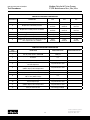
P1/PD Series – 18cc, 28cc, 45cc Medium Duty Axial Piston Pumps Variable Displacement – Service Information Bulletin HY28-2665-02/SVC/EN Effective: April 01, 2010 The product information, specifications, and descriptions contained in this publication have been compiled for the use and convenience of our customers from information furnished by the manufacturer; and we can not, and do not, accept any responsibility for the accuracy or correctness of any description, calculation, specification, or information contained herein. No such description, calculation, specification, or information regarding the products being sold has been made part of the basis of the bargain, nor has same created or amounted to an express warranty that the products would conform thereto. We are selling the goods and merchandise illustrated and described on this publication on an “as is” basis, and disclaim any implied warranty, including any warranty of merchantability or warranty of fitness for any particular purpose whatsoever, with respect to the goods and merchandise sold. All manufacturer warranties shall be passed on to our customers, but we shall not be responsible for special, indirect, incidental, or consequential damages resulting from the use of any of the products or information contained or described on this publication. Further, we reserve the right to revise or otherwise make product improvements at any time without notification. WARNING - USER RESPONSIBILITY FAILURE OR IMPROPER SELECTION OR IMPROPER USE OF THE PRODUCTS DESCRIBED HEREIN OR RELATED ITEMS CAN CAUSE DEATH, PERSONAL INJURY AND PROPERTY DAMAGE. This document and other information from Parker-Hannifin Corporation, its subsidiaries and authorized distributors provide product or system options for further investigation by users having technical expertise. The user, through its own analysis and testing, is solely responsible for making the final selection of the system and components and assuring that all performance, endurance, maintenance, safety and warning requirements of the application are met. The user must analyze all aspects of the application, follow applicable industry standards, and follow the information concerning the product in the current product catalog and in any other materials provided from Parker or its subsidiaries or authorized distributors. To the extent that Parker or its subsidiaries or authorized distributors provide component or system options based upon data or specifications provided by the user, the user is responsible for determining that such data and specifications are suitable and sufficient for all applications and reasonably foreseeable uses of the components or systems. OFFER OF SALE The items described in this document are hereby offered for sale by Parker-Hannifin Corporation, its subsidiaries or its authorized distributor. This offer and its accepteance are governed by the provisions stated in the detailed "Offer of Sale" elsewhere in this document. 2 Medium Duty Axial Piston Pumps P1/PD Maintenance 18cc, 28cc, 45cc Bulletin HY28-2665-02/SVC/EN Contents Contents Typical Characteristics............................................................................................................................................. 4 General Information................................................................................................................................................. 5 Trouble Shooting...................................................................................................................................................... 7 18cc & 28cc Pump Exploded View ........................................................................................................................ 10 45cc Pump Exploded View .................................................................................................................................... 11 Pump Exploded View Parts & Descriptions ........................................................................................................... 12 Seal Kits and Parts Kits ......................................................................................................................................... 15 “C” Compensator ................................................................................................................................................... 16 “L” Compensator .................................................................................................................................................... 17 “AL”, “AM”, “AN”, “AE”, “AF”, Compensator............................................................................................................ 19 Pump Disassembly Procedure .............................................................................................................................. 20 Compensator Disassembly Procedure .................................................................................................................. 22 Parts Inspection..................................................................................................................................................... 23 Rework Limits ........................................................................................................................................................ 24 Pump Assembly Procedure ................................................................................................................................... 25 Compensator Assembly Procedure....................................................................................................................... 28 Assembly Tools...................................................................................................................................................... 29 Test Procedure ...................................................................................................................................................... 31 Model Code Information ........................................................................................................................................ 33 Conversions and Formulas.................................................................................................................................... 34 Offer of Sale .......................................................................................................................................................... 39 Parker Hannifin Corporation Hydraulic Pump Division Marysville, Ohio USA 3 Medium Duty Axial Piston Pumps P1/PD Maintenance 18cc, 28cc, 45cc Bulletin HY28-2665-02/SVC/EN Typical Characteristics P1/PD Series Pump Model displacement outlet pressure speed (mobile version) Inlet pressure fluid viscosity fluid contamination SAE mounting ISO mounting weight 045 28 45 cm3/r continuous bar 280 * intermittent bar 320 peak bar 350 maximum – boosted inlet maximum – 1.0 bar abs inlet maximum – 0.8 bar abs inlet 18 rpm — — 3000 rpm 3200 3200 2600 rpm 2600 2700 2200 rpm 600 rpm 1800 rpm 1800 minimum rpm 600 maximum bar 10 rated bar 1.0 absolute (0.0 gage) minimum bar 0.8 absolute (-0.2 gage) peak bar 4.0 Absolute (3.0 gage) and less than 0.5 bar above inlet pressure rated bar 2.0 Absolute (1.0 gage) and less than 0.5 bar above inlet pressure range °C -40 to +95 rated cSt 6 to 160 cSt 5000 (for cold starting) cSt 5 ISO 20/18/14 maximum – 1.0 bar abs inlet maximum0.8 bar abs inlet case pressure fluid temperature 028 maximum minimum speed (industrial version) 018 maximum intermittent minimum intermittent rated maximum ISO flange SAE 82-2 (A) 101-2 (B) 21/19/16 101-2 (B) key shaft SAE 19-1, (A) 25-1, (BB) 25-1, (BB) spline shaft SAE 9T (A), 11T flange ISO 2 bolt 80mm 2 bolt 100 mm 2 Bolt 100mm key shaft ISO E20N E25N E25N end port kg 13 17 23 side port kg 13 18 24 thru-drive kg 14 18 27 13T, (B) 15T, (BB) 13T, (B) 15T, (BB) * Intermittent pressure is defined as less than 10% of operation time, not exceeding 6 successive seconds. 4 Parker Hannifin Corporation Hydraulic Pump Division Marysville, Ohio USA Medium Duty Axial Piston Pumps P1/PD Maintenance 18cc, 28cc, 45cc Bulletin HY28-2665-02/SVC/EN General Information MOUNTING These pumps are designed to operate in any position. The pump shaft must be in alignment with the shaft of the source driver and should be checked with a dial indicator. The mating pilot bore and coupling must be concentric. This concentricity is particularly important if the shaft is rigidly connected to the driven load without a flexible coupling. SHAFT INFORMATION Splined: The shafts will accept a maximum misalignment of 0.15mm, 0.005 inch, total indicator reading. Angular misalignment at the external and internal spline axis must be less than ± 0,002 mm per mm of shaft radius, ± 0.002 inches per inch of shaft radius. The coupling interface must be lubricated. PARKER recommends lithium molydisulfide or similar grease. The internal coupling should be hardened to Rc 27-34 and must conform to SAE-J498c, class 5 flat root side fit. Keyed: High strength heat treated keys must be used. Replacement keys must be hardened to 27-34 Rc. The key corners must be chamfered 0.81-1.0 mm, 0.032”-0.040”, at 45° to clear radii that exist in the keyway. SIDE LOAD CAPABILITY The P1/PD series is designed for inline-drive. Side loading on the shaft is not recommended. If this is unavoidable consult your nearest PARKER representative. FLUID CONNECTIONS Connect inlet and outlet lines to the port block of the pump. The maximum case pressure is 2 bar (30 psi) continuous, 4 bar (60 psi) intermittent. The case pressure must never exceed inlet pressure by more than .5 bar (7 psi). When connecting case drain line make certain that drain plumbing passes above highest point of the pump before passing to the reservoir. The case leakage line must be of sufficient size to prevent back pressure in excess of 2 bar (30 psi) and returned to the reservoir below the surface of the oil as far from the supply inlet as possible. All fluid lines, whether pipe, tubing, or hose must be adequate size and strength to assure free flow through the pump. An undersize inlet line will prevent the pump from operating properly at full rated speed. An undersize outlet line will cause back pressure and cause heat generation and increased noise. Flexible hose lines are recommended. If rigid piping is used, the workmanship must be accurate to eliminate strain on the pump port block or to the fluid connections. Sharp bends in the lines must be eliminated wherever possible. All system piping must be cleaned and flushed before installing pump. Make sure the entire hydraulic system is free of dirt, lint, scale, or other foreign material. Caution: Do not use galvanized pipe. Galvanized coating can flake off with continued use. SYSTEM RELIEF VALVES Although the P1/PD series pumps have very fast off-stroke compensator response, system relief valves are recommended in all cases for safety considerations. RECOMMENDED FLUIDS The fluid recommended for use in these pumps has a petroleum base and contains agents which provide oxidation inhibition and anti-rust, anti-foam and de-aerating properties as described in PARKER standard HF-1. Where anti-wear additive fluids are specified, see PARKER standard HF-0. VISCOSITY INDEX 90 V. I. minimum. Higher values extend the range of operating temperature but may reduce the service life of the fluid. TEMPERATURE Determined by the viscosity characteristics of the fluid used. Because high temperatures degrade seals, reduce the service life of the fluid and create hazards, fluid temperature should not exceed 110°C (230°F) at the case drain. MAINTENANCE The pump is self-lubricating and preventative maintenance is limited to keeping system fluid clean by changing filters frequently. Keep all fittings and screws tight. Do not operate at pressures and speeds in excess of the recommended limit. If the pump does not operate properly, check the troubleshooting chart before attempting to overhaul the unit. Overhauling may be accomplished by referring to the disassembly, rework limits of wear parts, and assembly procedures as provided in this service manual. FLUID CLEANLINESS Fluid must be cleaned before and continuously during operation, by filters that maintain a cleanliness level of ISO 20/18/14. Better cleanliness levels will significantly extend the life of the components. As contaminant generation may vary with each application, each must be analyzed to determine proper filtration to maintain the required cleanliness level. Parker Hannifin Corporation Hydraulic Pump Division Marysville, Ohio USA 5 Medium Duty Axial Piston Pumps P1/PD Maintenance 18cc, 28cc, 45cc Bulletin HY28-2665-02/SVC/EN General Information START UP PROCEDURE START UP PROCEDURE FOR NEW INSTALLATION • Read and understand the instruction manual. • • • • • • • • • • • • • • • • • • • Identify components and their function. Visually inspect components and lines for possible damage. Insure that all necessary ports are properly connected. Check reservoir for cleanliness. Drain and clean as required. Check fluid level and fill as required with filtered fluid to a minimum ISO cleanliness level of 20/18/14. Fill pump case with clean oil prior to starting. If pump is mounted vertically with the shaft up, bleed the air out the D1 drain port located near the mounting flange. Check alignment of drive. Check oil cooler and activate it, if included in circuit. Check fluid temperature. Reduce pressure settings of compensator and relief valve. Make sure accurate pressure readings can be made at appropriate places. If solenoids in system, check for actuation. Jog the pump drive. Check for proper shaft rotation. Make sure pump fills properly. Start the pump drive. Bleed system of air. Recheck fluid level. Cycle unloaded machine at low pressure and observe actuation (at low speed, if possible). Increase pressure settings gradually in steps. Check for leaks in all lines especially in pump and motor inlet lines. Make correct pressure adjustments. Gradually increase speed. Be alert for trouble as indicated by changes in sounds, system shocks, and air in fluid. Equipment is operational. 6 Parker Hannifin Corporation Hydraulic Pump Division Marysville, Ohio USA Medium Duty Axial Piston Pumps P1/PD Maintenance 18cc, 28cc, 45cc Bulletin HY28-2665-02/SVC/EN Trouble Shooting Component problems and circuit problems are often interrelated. An improper circuit may operate with apparent success but will cause failure of a particular component within it. The component failure can be the effect, not the cause of the problem. This general guide is offered to help in locating and eliminating the cause of problems by studying their effects. effect of trouble noisy pump Possible cause air in fluid cavitation in rotating group misaligned shaft mechanical fault in pump erosion on barrel ports and port plate high wear in pump air in fluid cavitation excessive loads contaminant particles in fluid improper fluid improper repair unwanted water in fluid Parker Hannifin Corporation Hydraulic Pump Division Marysville, Ohio USA fault which needs remedy leak in inlet line low fluid level turbulent fluid return lines above fluid level gas leak from accumulator excessive pressure drop in the inlet line from a pressurized reservoir inlet line strainer acting as air trap fluid too cold fluid too viscous fluid too heavy shaft speed too high inlet line too small inlet strainer too small inlet strainer too dirty operating altitude too high inlet pressure too low faulty installation distortion in mounting axial interference faulty coupling excessive overhung loads piston and shoe looseness or failure bearing failure incorrect port plate rotation eroded or worn parts in the displacement control see noisy pump above see noisy pump above reduce pressure settings reduce speeds improper filter maintenance filters too coarse introduction of dirty fluid to system reservoir openings improper reservoir breather improper line replacement fluid too thin or thick for operating temperature range breakdown of fluid with time/temperature/shearing effects incorrect additives in new fluid destruction of additive effectiveness with chemical aging incorrect parts incorrect procedures, dimensions, finishes Condensation faulty breather/strainer heat exchanger leakage faulty clean-up practice water in makeup fluid 7 Medium Duty Axial Piston Pumps P1/PD Maintenance 18cc, 28cc, 45cc Bulletin HY28-2665-02/SVC/EN Trouble Shooting effect of trouble pressure shocks compensator instability heating of fluid possible cause cogging load worn relief valve worn compensator slow response in check valves excessive decompression energy rates Barrel blow-off fault which needs remedy mechanical considerations needed repairs replace excessive line capacitance (line volume, line stretch, accumulator effects) excessive pump leakage reduce line size or lengths eliminate hose relief valve compensator pump too large for fluid needs heat exchanger reservoir replace or relocate improve decompression control rotating group worn, excessive case pressure recheck case drain flow and repair as required fluid too thin improper assembly, port timing set too low (compared to load or to compensator) instability caused by back pressure, worn parts set too high (compared to relief) worn parts select smaller pump displacement water turned off or too little flow water too hot fan clogged or restricted efficiency reduced by mud or scale deposits intermittent hydraulic fluid flow too little fluid improper baffles insulating air blanket that prevents heat rejection heat pickup from adjacent equipment 8 Parker Hannifin Corporation Hydraulic Pump Division Marysville, Ohio USA Medium Duty Axial Piston Pumps P1/PD Maintenance 18cc, 28cc, 45cc Bulletin HY28-2665-02/SVC/EN Notes Parker Hannifin Corporation Hydraulic Pump Division Marysville, Ohio USA 9 Medium Duty Axial Piston Pumps P1/PD Maintenance 18cc, 28cc, 45cc Bulletin HY28-2665-02/SVC/EN 18cc & 28cc Pump Exploded View 25 1 3 26 50 5 4 6 7 50 8 11 9 14 27 13 51 28 15 12 19 52 20 31 31 32 21 32 22 33 34 35 23 55 56 36 37 38 24 10 Parker Hannifin Corporation Hydraulic Pump Division Marysville, Ohio USA Medium Duty Axial Piston Pumps P1/PD Maintenance 18cc, 28cc, 45cc Bulletin HY28-2665-02/SVC/EN 45cc Pump Exploded View 25 1 3 26 50 5 4 7 50 8 11 9 27 14 13 51 28 12 19 52 20 31 31 32 21 32 22 33 34 35 23 55 56 36 37 Parker Hannifin Corporation Hydraulic Pump Division Marysville, Ohio USA 38 24 11 15 6 Medium Duty Axial Piston Pumps P1/PD Maintenance 18cc, 28cc, 45cc Bulletin HY28-2665-02/SVC/EN Pump Exploded View Parts & Descriptions Item Qty 1 4 3 1 4 5 7 8 1 2 1 3 9 1 10 11 12 13 14 15 17 19 20 21 22 23 24 25 26 2 1 1 1 1 1 1 1 1 2 3 1 1 1 9 018 Part # 210 x 209 N/A N/A N/A N/A N/A N/A N/A N/A N/A N/A 2050V-7 108X2V 299X67 605-10017-0 03E-94413-0 03E-94965-0 03E-94416-0 03E-94966-0 03E-94415-0 03E-94963-0 03E-94414-0 03E-94964-0 n/a 03E-94427-0 03E-94428-0 03E-94430-0 03E-94427-0 03E-94426-0 230-82515-0 256X521 787635 786996 787000 03E-94717-0 787002 786994 See Kits 028 Part # 210 x 211 N/A N/A N/A N/A N/A N/A N/A N/A N/A N/A 2-160V-7 108X2V 324-30014-0 605-10017-0 03E-94969-0 03E-94378-0 03E-94970-0 03E-94379-0 03E-94967-0 03E-94376-0 03E-94968-0 03E-94377-0 n/a 03E-94390-0 03E-94391-0 03E-94393-0 03E-94390-0 03E-94389-0 789815 256X525 03E-94387-0 03E-94388-0 03E-94386-0 03E-94375-0 03E-94385-0 03E-94384-0 See Kits EXPLODED VIEW COMPONENTS 045 Part # Model Code Description 361-12229 Socket head cap screw N/A P****S***E*2 Port Block S/A End Ported SAE Thread N/A P****S***E*0 Port Block S/A End Ported SAE Flange N/A P****A,M,B***E*2 Port Block S/A , End Ported Metric Thread N/A P****A,M,B***E*0 Port Block S/A , End Ported Metric Flange N/A P****S***R*2 Port Block S/A Side Ported SAE Thread N/A P****S***R*0 Port Block S/A Side Ported SAE Flange N/A P****A,M,B***R*2 Port Block S/A , Side Ported Metric Thread N/A P****A,M,B***R*0 Port Block S/A , Side Ported Metric Flange N/A P****S***T00A Port Block S/A Thru Drive SAE A N/A P****S***T00B Port Block S/A Thru Drive SAE B 675-00162 O-Ring Face Seal 108X2V (Not shown on port block) O-Ring Boss Plug 324-30014-0 Metric Split Spring Pin 605-10017-0 O-Ring 03E-94341-0 P1****R*****E,T Port Plate CW Mobile 03E-95374-0 P1****R*****R Port Plate CW Mobile with Low Ripple 03E-94342-0 P1****L******E,T Port Plate CCW Mobile 03E-95375-0 P1****L*****R Port Plate CCW Mobile with Low Ripple 03E-94339-0 PD****R****E,T Port Plate CW Industrial 03E-94675-0 PD****R*****R Port Plate CW Industrial with Low Ripple 03E-94340-0 PD****L*****E,T Port Plate CCW Industrial 03E-95080-0 PD****L*****R Port Plate CCW Industrial with Low Ripple 695-00912-0 O-Ring 03E-94355-0 Bias Guide 03E-94354-0 Bias Piston 03E-94356-0 Bias Spring 03E-94353-0 Control Guide 03E-94352-0 Control Piston 230-82227-0 Shaft Bearing 356-65144 Retaining Ring, Internal 03E-94350-0 Barrel Hold Down Spring 03E-94351-0 Barrel Hold Down Washer 03E-94349-0 Barrel Pin 03E-94338-0 Barrel - Ductil Iron 03E-94348-0 Ball Seat 03E-94347-0 Slipper Retainer See Kits Piston Assembly 12 Parker Hannifin Corporation Hydraulic Pump Division Marysville, Ohio USA Medium Duty Axial Piston Pumps P1/PD Maintenance 18cc, 28cc, 45cc Bulletin HY28-2665-02/SVC/EN Pump Exploded View Parts & Descriptions 27 1 28 31 32 33 34 35 36 37 1 2 2 38 50 51 52 53 54 55 56 2 2 1 1 1 1 1 1 1 1 1 1 1 1 1 1 2 1 1 1 1 1 1 03E-94409-0 N/A 03E-94410-0 N/A 22X61 03E-94800-0 N/A 03E-94434-0 03E-94718-0 03E-94804-0 N/A S2E-18416-0 03E-94359-0 03E-94432-0 N/A 108X6 3-906V-9 787140 256x535 324-30024-0 216-10013 230-82514-0 256X222 256X544 108X4 3-904V-9 Parker Hannifin Corporation Hydraulic Pump Division Marysville, Ohio USA EXPLODED VIEW COMPONENTS CONTINUED 03E-94372-0 03E-94335-0 P****01**** E,R Spline Shaft SAE. N/A 03E-94337-0 P****01****T Spline Shaft , Thru Drive 03E-94373-0 03E-94948-0 P****02****E,R Keyed Shaft SAE N/A 03E-94908-0 P****02****T Keyed Shaft ,SAE , Thru Drive 22x22 039-54076-0 P****02**** Key for “02” Shafts 03E-94903-0 03E-94923-0 P****04****E,R Keyed Shaft ISO N/A 03E-94922-0 P****04***T Keyed Shaft , ISO, Thru Drive 03E-95199-0 03E-94360-0 P****04**** Key For “04” ISO Shafts N/A N/A P****06**** E,R Spline Shaft SAE A , 9T 03E-95166-0 03E-94990-0 P****08**** E,R Spline Shaft SAE B , 13T N/A 03E-95197-0 P****08**** T Spline Shaft SAE B , Thru Drive S2E-18414-0 S2E-18412-0 Cam Plate Assembly 03E-94359-0 03E-94359-0 Bearing Retainer Orifice Screw 03E-94395-0 03E-94358-0 Cam Bearing N/A N/A Housing ( Not Sold Separately) 108X8 488-35055-0 O-Ring Boss Plug 695-00908-0 695-00910-0 O-Ring P2-060-3304 620-82125-5 Shaft Seal (Viton) 256X544 356-65158-0 Retaining Ring, Internal S2E-17904-5T P*******R****C00 Pressure Compensator, 80-280 Bar ,CW S2E-17905-5T P*******L****C00 Pressure Compensator, 80-280 Bar, CCW S2E-18285-5T P*******R****C10 Pressure Compensator, 20-80 Bar ,CW S2E-18286-5T P*******L****C10 Pressure Compensator, 20-80 Bar, CCW S2E-18745-5T P*******R****AM0 Remote Compensator, CW S2E-18746-5T P*******L****AM0 Remote Compensator, CCW S2E-17823-5T P***S***R****L00 Load Sense, CW , SAE S2E-17824-5T P***S***L****L00 Load Sense, CCW , SAE S2E-17936-5T P***A,B***R****L0 Load Sense, CW , BSPP S2E-17937-5T P***A,B***L****L0 Load Sense, CCW , BSPP S2E-18584-5T P***S***R****L2 Load Sense w/ Bleed, CW , SAE S2E-18586-5T P***S***L****L2 Load Sense w/ Bleed, CCW , SAE 324-30024-0 324-30014-0 Dowel Pin, Cover 789814 230-82227-0 Bushing, Port Block 789815 230-82516-0 Cylindrical Roller Bearing 256X221 356-65159-0 Retaining Ring, External 256X544 n/a Retaining Ring, Internal 108X4 108X4 O-Ring Boss Plug 3-904V-9 3-904V-9 O-Ring 13 Medium Duty Axial Piston Pumps P1/PD Maintenance 18cc, 28cc, 45cc Bulletin HY28-2665-02/SVC/EN Pump Exploded View 39 40 41 3 42 49 48 14 46 47 45 44 43 15 CASE TO INLET CHECK VALVE, 018, 028, 045 Item No Quanty Part Number Model Code Description 39 1 314-10002-0 P******E,R,T*1,3 Hollow Set Screw 40 1 03E-94720-0 P******E,R,T*1,3 Check Valve Poppet 41 1 03E-94721-0 P******E,R,T*1,3 Spring 42 1 03E-94722-0 P******E,R,T*1,3 Check Valve Stop Minimum and Maximum Displacement Stop Item No Quantity 018 Part Number 028 Part Number 045 Part Number Model Code Description 43 1 362-11045-0 P******E,R1,2,3 Adjusting Screw 44 1 334-00013-0 P******E,R1,2,3 Locknut 45 1 03E-93181-0 P******E,R1,2,3 Volume Stop Plug 46 1 695-00011-0 P******E,R1,2,3 O-Ring 47 1 618-15023-0 P******E,R1,2,3 Back Up Ring 48 1 695-00908-0 P******E,R1,2,3 O-Ring 49 1 03E-94736-0 03E-95170-0 03E-93262-0 P******E,R1,3 Max Volume Stop Rod 49 1 03E-95217-0 03E-95358-0 03E-93262-0 P******E,R2,3 Min Volume Stop Rod 50 2 488-35018-0 14 P*045**U*E,R0 Plug , Not Shown Parker Hannifin Corporation Hydraulic Pump Division Marysville, Ohio USA Medium Duty Axial Piston Pumps P1/PD Maintenance 18cc, 28cc, 45cc Bulletin HY28-2665-02/SVC/EN Seal Kits and Parts Kits Thru Drive Pad and Coupling Model Code Thru Drive Couplings O-Ring 018 028 045 SAE A Thru Drive , 9T Spline P******T**A N/A N/A 03E-94942-0 695-00237-0 SAE A Thru Drive , 11T Spline P******T**H N/A N/A 03E-94943-0 695-00237-0 SAE B Thru Drive , 13T Spline P******T**B N/A N/A 03E-94945-0 695-00243-0 SAE BB Thru Drive , 15T Spline P******T**Q N/A N/A 03E-94361-0 695-00243-0 Model Code 018 028 045 Adjustable Displacement Kits P*****1,2,3 S2E-19203-5 S2E-19204-5 S2E-19114-5K Seal Kits P****S**5 S2E-18709-5K S2E-19198-5K S2E-19066-5K Model Code 018 028 045 P1****R*****E,T S2E-18710-0K S2E-19119-0K S2E-19067-0K P1****R*****R S2E-19205-0K S2E-19209-0K S2E-19235-0K P1****L******E,T S2E-18711-0K S2E-19120-0K S2E-19068-0K P1****L*****R S2E-19206-0K S2E-19210-0K S2E-19236-0K CW Industrial PD****R****E,T S2E-18712-0K S2E-19121-0K S2E-19069-0K CW Industrial with Low Ripple PD****R*****R S2E-19207-0K S2E-19211-0K S2E-19126-0K PD****L*****E,T S2E-18713-0K S2E-19122-0K S2E-19070-0K PD****L*****R S2E-19208-0K S2E-19212-0K S2E-19127-0K Rotating Group Kits CW Mobile CW Mobile with Low Ripple CCW Mobile CCW Mobile with Low Ripple CCW Industrial CCW Industrial with Low Ripple Rotating Group Kit includes barrel s/a, pistons, retainer, washer, pins, port plate Torque Limiter Control Kits Model Number 018 028 045 Torque Limiter Kit for AMT Control P*045AMT N/A N/A S2E-19102-5 Torque Limiter Kit for ALT Control P*045ALT N/A N/A See Note Note: “AL*” control can be converted from “AM*” control with spool conversion kit S2E-19117-0 Parker Hannifin Corporation Hydraulic Pump Division Marysville, Ohio USA 15 Medium Duty Axial Piston Pumps P1/PD Maintenance 18cc, 28cc, 45cc Bulletin HY28-2665-02/SVC/EN “C” Compensator Outer spring used C0 only. Inner spring used for both C0 and C1 versions. NOTE: Individual parts are not available. The compensator is sold as a complete assembly only. Compensator Repair Part Number Rotation C0 80 - 280bar (1150 - 4000 psi) C1 20 - 80 bar (300 - 1150 psi) CW S2E-17904-5 T S2E-18285-5 T CCW S2E-17905-5 T S2E-18286-5 T Item no. Quantity Description NOTES / Tightening Torque Compensator body CW rotation 1 1 2 1 Spool 3 1 Spring seat 4 1 Outer spring 5 1 Inner spring 6 1 Spring seat & piston 7 1 Seal piston o-ring 8 1 Spring cap o-ring 9 1 Spring cap 10 1 Adjusting screw 11 1 Adjusting screw locknut 7.9 ± 0.8 N-m (70 ±7 in-lbs) 12 1 Socket set screw (Loctite 242) 3.4 ± 0.4 N-m (30 ± 3 in-lbs) 13 4 Hex mounting screw 5.0 ± 0.3 N-m (45 ± 3 in-lbs) 14 1 SAE #2 o-ring 15 1 Hardened SAE #2 o-ring boss plug 4.0 ± 0.6 N-m (35 ± 5 in-lbs) 16 1 Orifice plug 17 4 Teflon O-ring 18 1 Roll pin 19 1 Teflon O-ring Compensator body CCW rotation C0 versions only 115 ± 7 N-m (85 ± 5 ft-lbs) (Loctite 242) 3.4 ± 0.4 N-m (30 ± 3 in-lbs) 16 Parker Hannifin Corporation Hydraulic Pump Division Marysville, Ohio USA Medium Duty Axial Piston Pumps P1/PD Maintenance 18cc, 28cc, 45cc Bulletin HY28-2665-02/SVC/EN “L” Compensator NOTE: Individual parts are not available. The compensator is sold as a complete assembly only. See Notes: 21 22 23 24 27 13 12 11 15 14 16 17 18 19 20 10 3 2 1 26 25 4 7 9 8 6 5 Outer spring used L0 and L2 versions only. Inner spring used L0, L1, L2, and L3 versions Compensator Repair Part Number Port Rotation L0 80 - 280bar (1150 - 4000 psi) L2 80 - 280bar (1150 - 4000 psi) SAE CW S2E-17823-5 T S2E-18584-5 T CCW S2E-17824-5 T S2E-18586-5 T CW S2E-17939-5 T N/A CCW S2E-17938-5 T N/A S2E-17937-5 T N/A S2E-17936-5 T N/A ISO BSPP CW CCW Parker Hannifin Corporation Hydraulic Pump Division Marysville, Ohio USA 17 Medium Duty Axial Piston Pumps P1/PD Maintenance 18cc, 28cc, 45cc Bulletin HY28-2665-02/SVC/EN “L” Compensator sectional view 8 1 Main Compensator Spring cap o-ring 9 1 Main Compensator Spring cap 10 2 Adjusting screw 11 2 Adjusting screw locknut 7.9 ± 0.8 N-m (70 ±7 in-lbs) 12 1 Load Sense Compensator Spring cap 36.5 ± 1.5 N-m (27 ± 1 ft-lbs) 13 1 Load Sense Compensator Spring cap oring 14 1 Load Sense Compensator Piston backup ring 15 1 Load Sense Compensator Piston Oring 16 1 Load Sense Compensator Seal Piston 17 1 Load sense compensator spring 18 1 Load sense compensator spring seat 19 1 Load sense compensator spool 20 1 Socket set screw (Loctite 242) 3.4 ± 0.4 N-m (30 ± 3 in-lbs) Socket set screw L0 versions 21 1 Orifice L2 versions 22 3 SAE #2 o-ring boss plug 4.0 ± 0.6 N-m (35 ± 5 in-lbs) 23 5 SAE #2 o-ring 24 2 Hardened SAE #2 o-ring boss plug 25 4 Teflon O-ring 26 1 Roll pin 27 4 Hex mounting screw 115 ± 7 N-m (85 ± 5 ft-lbs) (Loctite 242) 3.4 ± 0.4 N-m (30 ± 3 in-lbs) 4.0 ± 0.6 N-m (35 ± 5 in-lbs) 5.0 ± 0.3 N-m (45 ± 3 in-lbs) 18 Parker Hannifin Corporation Hydraulic Pump Division Marysville, Ohio USA Medium Duty Axial Piston Pumps P1/PD Maintenance 18cc, 28cc, 45cc Bulletin HY28-2665-02/SVC/EN “AL”,“AM”,“AN”,”AE”,”AF” Compensator NOTE: Individual parts are not available. The compensator is sold as a complete assembly only. Compensator Repair Part Number Rotation AM* AN* AL* AE* AF* CW S2E-18745-5T S2E-18743-5T S2E-19107-5T S2E-18747-5T S2E-18749-5T CCW S2E-18746-ST S2E-18744-5T S2E-19108-5T S2E-18748-5T S2E-18750-5T Note: To convert “AM*” to “AL*”, use conversion kit S2E-19117-0 CCW DIRECTION OF ROTATION AN Control B V .8mm P ISO 4401 Interface T BG D3 D2 A D1 AM Control B V .8mm BG D3 D2 A D1 AE & AF Control B V .8mm P T BG 4VP01 D3 D2 A Parker Hannifin Corporation Hydraulic Pump Division Marysville, Ohio USA D1 19 Torque to 5.0 Nm (45.in lbs.) CW Medium Duty Axial Piston Pumps P1/PD Maintenance 18cc, 28cc, 45cc Bulletin HY28-2665-02/SVC/EN Disassembly Procedure Pump disassembly for inspection should be limited to the following cases: a) Malfunction or oil leakage resulting from damage or wear and tear. b) Trouble-shooting procedures previously listed do not solve the problem. For rotation change or shaft conversion, disassembly should be done only as far as necessary to complete conversion. Disassembly and reassembly should be performed in a clean environment. Caution: Spring assemblies in the pump are normally set under high compression and bodily injury may occur if caution is not taken during disassembly. It is usually not necessary to replace spring (20) fitted in cylinder barrel. Do not replace the spring unless absolutely necessary. After disassembly, the internal parts should be coated with a film of clean oil and protected from dirt and moisture. It is recommended that the length of the protruding portion of the compensator adjusting screws, on the control 38 be measured and noted as this information will prove useful during assembly. Care must be taken to avoid dropping, damaging or contaminating the machined parts and the control valve. For complete overhaul, all o-rings and seals should be discarded and replaced. 1. Identify the pump from information on the data tag. Figure 1 Figure 1 20 Parker Hannifin Corporation Hydraulic Pump Division Marysville, Ohio USA Medium Duty Axial Piston Pumps P1/PD Maintenance 18cc, 28cc, 45cc Bulletin HY28-2665-02/SVC/EN Disassembly Procedure 2. Drain fluid from housing. Fluid drained from pump should be disposed of properly. 3. Mount pump in fixture to prevent movement while removing main housing bolts 4. Remove bolts holding the compensator assembly on the pump housing. Additional fluid may drain out of the passages when the compensator is removed. Set compensator aside for later disassembly and inspection 5. Remove the bolts attaching the port block to the main housing. 6. Carefully remove the port block. Use caution to avoid dropping the port plate. Note the location of the bias spring - piston assembly and the control piston assembly. The control piston, bias piston and bias spring may remain in pump when port block is removed. Remove and discard the three white Teflon seals on the port block. These seals should be replaced each time the pump is disassembled. 7. Remove the control piston and the bias piston - spring assembly. NOTE: For rotation change only, do not disassemble further, proceed to step 16. 8. Position the pump horizontally and remove the rotating group. Avoid separating the pistons from the barrel if possible. This will assist in identifying damage between an individual piston and bore during component inspection. Large Pocket Pressure control side of pump Parker Hannifin Corporation Hydraulic Pump Division Marysville, Ohio USA Figure 2 21 Medium Duty Axial Piston Pumps P1/PD Maintenance 18cc, 28cc, 45cc Bulletin HY28-2665-02/SVC/EN Disassembly Procedure DISASSEMBLY PROCEDURES Continued 9. Remove Cam from housing. 10. Remover cam bushing screws and cam bushings from pump. 11. Remove snap ring in housing and shaft bearing assembly. 12. If completing a seal change or complete overhaul, turn the housing over and remove the snap ring and shaft seal from the housing. Note: Install a new seal do not reuse the shaft seal. 13. If there is excessive wear on the port block bushing; remove the bushing from the port block. 14. If complete overhaul or rotation change, remove control piston and bias piston guides. (45 Size only) COMPENSATOR DISASSEMBLY NOTES: Access plugs on end of compensator spool bores are hardened plugs. Do not interchange with other plugs in the control. For rotation change, the complete compensator assembly will need to be replaced. 1. Measure and record the extension of the two pressure adjusting screws. 2. Carefully remove the main compensator spring cap. Remove the two springs. Remove the seal piston and spring seat. Remove the o-ring boss access plug on the opposite side of the compensator. Remove the compensator spool. NOTE: the compensator spool and inner spring are not interchangeable with the load sense compensator spool and spring. 3. Load sense compensator: Carefully remove the load sense compensator spring cap with spring seat/seal piston. Remove the spring. Remove the spring seat. Remove the o-ring boss access plug on the opposite side of the compensator. Remove the load sense compensator spool. NOTE: the load sense compensator spool and spring are not interchangeable with the main compensator spool and inner spring of the main compensator. 4. Remove all SAE o-ring boss access plugs. Proceed to inspection section of this manual. 22 Parker Hannifin Corporation Hydraulic Pump Division Marysville, Ohio USA Medium Duty Axial Piston Pumps P1/PD Maintenance 18cc, 28cc, 45cc Bulletin HY28-2665-02/SVC/EN Inspection INSPECTION COMPENSATOR INSPECTION Parker Hannifin Corporation Hydraulic Pump Division Marysville, Ohio USA Carefully clean and dry all parts prior to inspection. Refer to chart 1 for dimensional information regarding allowable tolerances. 1. Examine piston diameters for scratches or gouges. If any piston is severelydamaged, note which piston bore it came out of. Extra attention should begiven to that bore in step 2. Check end play of piston shoe assembly. Checkthe bottom surface of the shoes for damage. The shoe surface should besquare and flat. Measure the depth of the pocket of the shoe. Shoes may belapped as a set if the pocket depth is within allowable limits. Confirm pocketdepth after lapping to insure it is still within limits. 2. Examine bores in cylinder for scratches Check diameter of bores in 4different locations, including near the bottom of the barrel where the pistondoes not travel. If the dimensions vary by more than 0.0102 mm (0.0004 in.)or any dimension exceeds the allowable limit, the barrel needs to bereplaced. Examine the barrel face for scratches and gouges. The barrel canbe reworked if dimensions are with specifications listed in chart 1. 3. The port plate can be lapped lightly if the face is only lightly scratched, otherwise it should be replaced. 4. Examine the retainer plate in the area of contact with the piston shoes. Anymarks beyond light polishing indicate that replacement is necessary. Check the surface of the spherical area of the retainer plate and the spherical guide ball. Inspect the back surface of the spherical guide ball where the load pins make contact. If indentations are present replace the guide ball. 5. Examine cam on top and bottom surface. If scratches or gouges appear to penetrate the surface treatment, the cam must be replaced. 6. The cam bearings cannot be reworked and should be replaced if worn through the Teflon surface. 7. Both the bias piston and the compensator piston should move freely in their respective bores. The pistons and bores should be free of scratches or gouges. 8. The seal area of the drive shaft should be smooth and not have marks due to seal wear. Keyed shafts should be inspected for signs of brinelling and damage to the key area. Splined shafts may have a contact wear pattern but should not show excessive wear on the spline area. NOTE: Spinning on shaft for P1/PD-018, 028 and 045 the cylindrical bearing should not have any signs of roller spalling, brinelling or discoloration. The bearing should be free to rotate without bind or rough feel. NOTE: The compensator is supplied as an assembly. Individual parts are not available. If there is significant damage to any of the parts, the complete compensator will need to be replaced. 1. Inspect the main compensator spool and the load sense spool for scratches or other damage. 2. Inspect the springs for proper free extension length (see chart). 3. Inspect the spool bores for damage. Apply a light oil film on the appropriate spool and check its fit in the bore. The spool should fit snugly in housing and not have any radial play. 23 Medium Duty Axial Piston Pumps P1/PD Maintenance 18cc, 28cc, 45cc Bulletin HY28-2665-02/SVC/EN Rework Limits Chart 1 Rework Limits 018 Part No 028 Part No Item Number Component 20 Barrel Spring 787635 03E-94387-0 39.5 mm 03E-94350-0 48.3 mm Free Height +/- .2mm 13 Bias Spring 03E-94430-0 78.3 mm 03E-94393-0 87.5 mm 03E-94356-0 116.4 mm Free Height +/- .2mm 26 23 Piston Barrel 045 Part No Tolerances Measure OD in 3 places, top, middle and Max End Play Max End Play Max End Play bottom. Measurement 0.10 mm 0.07 mm 0.10 mm should not vary by more than .01 mm Min Shoe Min Shoe Min Shoe Flange Flange Flange End Play between Thickness Thickness Thickness piston and shoe should 2.97 mm 3.98 mm 4.98 mm not exceed value shown 03E-94717-0 03E-94375-0 Measure piston bore ID in 3 places , top, middle, bottom. Measurement should not vary by more than 03E-94338-0 0.01 mm. Max material to be removed by lapping is .0051 mm C0 P Max Compensator Spring-Outer 03E-93158-0 39 mm Free Height : +/- .2mm C0 P Max Compensator Spring- Inner 03E-93159-0 26 mm Free Height : +/- .2mm L0 Load Sense Spring 03E-93825-0 14 mm Free Height : +/- .2mm 24 Parker Hannifin Corporation Hydraulic Pump Division Marysville, Ohio USA Medium Duty Axial Piston Pumps P1/PD Maintenance 18cc, 28cc, 45cc Bulletin HY28-2665-02/SVC/EN Assembly Procedure For major overhauls, all plugs should be removed, and the seals replaced. Prior to assembly, all parts should be thoroughly cleaned. Assembly should be performed in a clean work environment. Do not use bearing grease during installation. Grease does not dissolve in hydraulic oil and may plug orifices or filters in the system. Clean petroleum jelly is preferred to lubricate o-rings and seals, and to adhere parts for assembly. NOTE: For fluids other than petroleum based hydraulic oil, insure that petroleum jelly is compatible with the fluid. If not compatible, another product should be used instead. Inspect all bearing surfaces and seal areas to insure that they are free from nicks, dings, scratches, and rust. 1. The P1/PD-018, 028 and 045 assembly will use step 2 to install the shaft seal. For P1/PD-018, 028 and 045 front bearing installation go to step 3. 2. Turn housing over. Using installation tool T1, press the shaft seal in the seal bore. Install the snap ring into the groove in the seal housing bore. 3. Install cylindrical bearing on pump shaft (slip fit). Install external retaining ring to hold bearing in place on the shaft. Insert shaft assembly into the pump housing with the bearing sliding into the bearing diameter in the housing. Install internal retaining ring into the housing. 4. If barrel hold down spring was removed during disassembly process, install three pins to slots in barrel spline (45 Size only). Petroleum jelly can be used to hold pins in place while installing remaining parts. (Figure 4) Place barrel on fixture with pin side down. Install backup washer and hold down spring and second back up washer. Compress spring in press and install snap ring. Caution: Make sure snap ring is properly seated in groove prior to removing barrel from press. Axial movement Figure 4 Parker Hannifin Corporation Hydraulic Pump Division Marysville, Ohio USA 25 Medium Duty Axial Piston Pumps P1/PD Maintenance 18cc, 28cc, 45cc Bulletin HY28-2665-02/SVC/EN Assembly Procedure 5. Apply a light film of oil into the piston bores. Lightly lubricate the spherical surface of the guide ball. Install the nine pistons into the bores in the hold down plate. Install the spherical guide ball into the hold down plate. While holding the guide ball against the hold down plate, install the pistons into the barrel. 6. Install the locating pin on the port block face. 7. For 045: Apply Loctite Primer Grade T to guide threads and allow to dry. Install unlubricated o-rings on the control guide and bias guide. Apply Loctite 271 to guide threads. For left hand rotation the bias guide is installed nearest to the dowel pin (figure 5A.) For right hand rotation the control guide is installed nearest to the dowel pin (figure 5B.) Torque the control and bias guides as specified in Chart 3. For 018, 028: The guides are identical and press fit into the holes. (Not shown in picture below) Chart 3 Pump Control and bias guide torque 018 Press Fit 028 Press Fit 045 Bias Piston Guide 142 N.M./105 ft lbs 045 Picture Locating pin Control Piston Guide Figure 5A Port Block with Left Hand configuration Figure 5B Port Block with Right Hand configuration 8. Apply light oil film to control piston and install it in the control guide bore. 9. Apply light oil film to the bias piston. Install the bias spring and the bias piston in the bias piston guide bore. 10. Apply a light layer of petroleum jelly to the back surface of the port plate. Install the port plate on the port block, lining up the slot on the port plate with the locating pin. (Ref Figure 6) 11. Install the large o ring in the groove on the port block. Install the three teflon o rings on the pressure communication ports of the port block. 12. Install the cam bearings in the cradle area of the housing. The chamfer on the back of the bearing must face the outer wall of the housing. Use Loctite Primer Grade “T” or other suitable primer on screws and mating threads in housing. Apply Loctite #242 (use sparingly) to screw threads and install orifice screws to hold bearings in place. Torque screws to 3.4 ± 0.25 Nm (33 ± 3 in-lb). 13. Place thin film of clean oil on cam bearing surfaces. Install cam in housing. For 045, the cam must be tilted to permit entry into the housing. (Figure 2) NOTE: The large pocket on the bottom surface of the cam must be on the same side as the three pressure communication holes on the main housing. Pump rotation does not affect the assembly of the cam. 14. Install the drive shaft into the pump housing. Position pump horizontally. Install the rotating group over the pump shaft. Rotate the barrel to insure that it is seated against the cam. Insure that the pump shaft is seated properly in the front bearing. 26 Parker Hannifin Corporation Hydraulic Pump Division Marysville, Ohio USA Medium Duty Axial Piston Pumps P1/PD Maintenance 18cc, 28cc, 45cc Bulletin HY28-2665-02/SVC/EN Assembly Procedure 15 Confirm that compensator rotation, port plate rotation, control and bias piston location indicate same direction of rotation. Chart 4 Pump Housing bolt torque 018 51 N.M./38 ft lbs 028 70 N.M./52 ft lbs 045 85 N.M./63 ft lbs 16 Carefully install the assembled port block on the pump housing. Press the port block to compress the bias spring and install housing bolts. Tighten the bolts in a cross pattern to insure the port block does not get cocked on the housing. When port block is seated on the housing, torque bolts in a cross pattern as specified in chart 4. 17. Install o-ring seals and assembled compensator on side of pump housing. Pump rotation is indicated by arrow on compensator housing. Torque bolts to 5 ± 0.25 Nm (45 ± 3 in-lb). (See Figure 7) Industrial port plates note slot length and quantity Mobile port plates Figure 6 CCW port plates CW port plates Dowel CCW CW compensator Figure 7 CCW pump with compensator Parker Hannifin Corporation Hydraulic Pump Division Marysville, Ohio USA 27 CW pump with compensator Medium Duty Axial Piston Pumps P1/PD Maintenance 18cc, 28cc, 45cc Bulletin HY28-2665-02/SVC/EN Assembly Procedure COMPENSATOR ASSEMBLY NOTE: instructions are for load sense compensator. for other compensator types disregard steps related to extra spool assembly. Carefully clean and dry all parts prior to assembly. Use caution to insure that spools and other parts are not damaged during cleaning process. Use clean oil to lubricate seals and spools for easier assembly. 1. Remove and discard all o-rings. Install new o-rings on SAE boss plugs and seal pistons. 2. Apply a light film of oil to the o-ring on the main compensator seal piston. Install the main compensator seal piston in the main compensator spring cap. 3. Place inner compensator spring on seal piston. Install the outer compensator spring over the inner spring on the seal piston. Position the spring seat over the springs. Insert this assembly into the main compensator housing bore. Torque the main compensator spring cap to 169-183 Nm (125-135 ft.-lb.). 4. Apply a light film of oil on the main compensator spool (the longer of the 2 spools). Insert the spool into the spool bore opposite the main compensator spring assembly in the compensator body. The rounded end of the spool should be installed first so it will contact the spring seat. Install a new o-ring on the hardened SAE boss fitting and place it into the port. Torque fitting to 4 p 0.5 Nm (37 p 5 in-lb). 5. Apply a light film of oil to the o-ring on the load sense seal piston. Install the load sense compensator seal piston seat in the load sense spring cap. Install the load sense spring over the seal piston. Position the spring seat over the spring. Install this assembly into the load sense bore of the compensator housing. Torque the load sense spring cap to 35-38 Nm (26-28 ft. lb.). 6. Apply a light film of oil to the load sense compensator spool (the shorter of the 2 spools). Insert the spool into the spool bore opposite the load sense spring assembly. The spool should be installed with the rounded end in first so it will contact the load sense spring seat. Install a new o-ring on the hardened SAE boss fitting and place it into the port. Torque fitting to 4 p 0.5 Nm (37 p 5 in-lb). 7. Install o-rings on remaining SAE boss fittings and install into housing. Torque SAE-2 fittings to 4 p 0.5 Nm (37 p 5 in-lb). Main Outer Spring Load Sense Spool Load Sense Spring Main Compensator Inner Spring Main Compensator Spool 28 Parker Hannifin Corporation Hydraulic Pump Division Marysville, Ohio USA Medium Duty Axial Piston Pumps P1/PD Maintenance 18cc, 28cc, 45cc Bulletin HY28-2665-02/SVC/EN Assembly Tools 133 mm (5.250 in) 18.5 mm (0.728 in) D 8.0 mm (0.3150 in) A DIA B DIA 3.0 mm (.12 in) RADIUS 31.2 mm (1.250 in) DIA. C DIA 1.5 mm x 45 ˚ TYP. (.06 in X 45 ˚ ) U-CUT T1 Seal installation tool A B C D (018) 2.250 1.62 1.18 0.406 (028) 2.250 2.00 1.378 0.447 (045) 2.250 1.600 1.142 0.579 A B C 30˚ D F +0.05 / -0.00mm DIA BORE (+0.002 / - 0.000 in) E +/- 0.05mm DIA. (+/- 0.002 in) BLEND RADIUS & POLISH O.D. T3 Seal Guard A 76.20 mm 3.00 in. B 50.80 mm 2.00 in. C 19.05 mm .75 in. P18 “06” Shaft 76.20 mm 3.00 in. 50.80 mm 2.00 in. 19.05 mm .75 in. P28 / P45 “01”, “02”, “04 Shafts 76.20 mm 3.00 in. 50.80 mm 2.00 in. P18/ P28 / P45 “08” Shaft 76.20 mm 3.00 in. 50.80 mm 2.00 in. P18 “01”, “02”, “04” Shafts Parker Hannifin Corporation Hydraulic Pump Division Marysville, Ohio USA 29 D E 28.82 mm 1.135 in. F 20.45 mm .805 in. 15 deg 28.82 mm 1.135 in. 16.76 mm .66 in. 19.05 mm .75 in. 15 deg 38.10 mm 1.50 in. 26.00 mm 1.024 in. 19.05 mm .75 in. 15 deg 28.82 mm 1.135 in. 22.50 mm .885 in. 15 deg Medium Duty Axial Piston Pumps P1/PD Maintenance 18cc, 28cc, 45cc Bulletin HY28-2665-02/SVC/EN Assembly Tools T2 Front Bearing P1/PD45 Installation Tool mm ( in ) 89.75 ( 3.53) 20.00 177.80 (0.787) (7.00) 50.80 ( 2.00) 29.92 ( 1.178) 25.40 (1.00) T5 Rear Bushing Installation Tool mm ( in ) 101.60 ( 4.00) A 19.05 ( 0.75) B 25.40 ( 1.00) 50.80 ( 2.00) 38.10 ( 1.50) Pump Size 12.7 ( 0.5) A 3.71 mm 0.146 in. B 19.96 mm 0.786 in. 28 4.00 mm 0.157 in. 21.97 mm 0.865 in. 45 4.00 mm 0.157 in. 24.97 mm 0.983 in. 18 30 Parker Hannifin Corporation Hydraulic Pump Division Marysville, Ohio USA Medium Duty Axial Piston Pumps P1/PD Maintenance 18cc, 28cc, 45cc Bulletin HY28-2665-02/SVC/EN Test Procedure PUMP TEST PROCEDURE Test criteria based on hydraulic oil ISO 32 per Parker HF-0 specifications. Oil temperature: 50oC p 2oC (120oF p10oF). NOTE: insure that the hydraulic system does not overheat during this test procedure. Operating speed: 0 - 2300 rpm p 30 rpm. Case pressure: Maximum 14.5 psi (1 bar) 1. Mount pump on test fixture. Insure that shaft alignment is within specified tolerances. 2. Fill case with clean oil. Connect upper drain port to reservoir with no restrictions. Insure other drain ports are properly plugged. 3. Connect inlet and pressure lines. Insure that lines are filled with oil. Refer to circuit below. For units with “L” compensators, connect a suitable pilot line from port “X” to the pump discharge pressure line, down stream of the non-compensating flow valve. 4. Confirm direction of rotation for pump and drive are correct. 5. Reduce the main compensator setting to minimum. For units with “L” compensators, advance the load sense compensator adjustment until it bottoms out, and lock into position. 6. Set maximum volume stop (if included) to full displacement. If minimum volume stop is included, back adjustment all of the way out. 7. If possible, gradually increase pump speed to 1800 p30 rpm with no load. 8. Screw in compensator adjusting screw until it bottoms out, with no pressure on system load-relief valve. 9. Break-in pump at times and pressures listed below. Adjust the load-relief valve to the pressure listed for the times indicated. After break-in, reduce compensator setting to 280 bar (4060 psi), and adjust system load relief to cause pump to compensate three times to verify that pump compensates on and off stroke properly. Time 30 seconds 30 seconds 30 seconds Pressure 62-69 Bar 900-1000 psi 200-207 Bar 2900-3000 psi 269-276 Bar. 3900-4000 psi TEST CIRCUIT 1. 2. 3. 4. 5. 6. 7. 8. 9. 10. 11. 12. 13. Test pump Test stand prime mover Pump pressure gauge Non-compensating flow control Load pressure gauge Load relief valve Safety bypass relief valve Main flow meter Case drain pressure gauge Case drain flow meter Filter assembly with bypass Cooler assembly with bypass Reservoir 6 5 4 3 8 1 2 7 11 EM “X” 12 NOTE: Items 4 and 5 are required for load sense pump test. 13 9 10 Circuit 1 Parker Hannifin Corporation Hydraulic Pump Division Marysville, Ohio USA 31 Medium Duty Axial Piston Pumps P1/PD Maintenance 18cc, 28cc, 45cc Bulletin HY28-2665-02/SVC/EN Test Procedures PERFORMANCE SPECIFICATIONS PUMP WITH PRESSURE COMPENSATOR STEP REFERENCE CONDITION 018 028 045 1 Rated Speed 1800 1800 1800 4 Output Flow at minimum pressure 32 lpm minimum 49 lpm minimum 80 lpm minimum 5 Output Flow at rated pressure of 280 bar 30 lpm minimum 47 lpm minimum 77 lpm minimum 6 Case leakage at rated pressure of 280 bar 1.6 lpm 2.3 lpm 5.3 lpm 9 Case leakage when compensated at 280 bar 3.75 lpm 3.95 lpm 6.7 lpm 10 Input Torque when compensated at 280 bar 17.5 Nm 21.2 Nm 42 Nm 11 Output Flow when pressure reduced to 273 bar with compensator set at 280 bar 30 lpm minimum 47 lpm minimum 77 lpm minimum PERFORMANCE SPECIFICATIONS PUMP WITH PRESSURE COMPENSATOR STEP REFERENCE CONDITION REQUIRED VALUE 1 Set the pump speed to 1800 RPM 1800 rpm 2 Increase pump pressure compensator adjustment to maximum. n/a 3 Record input oil temperature 43-54 ° C (110 – 130 °F) 4 Set output load pressure to minimum. Record output flow see performance chart 5 Set output load pressure to 280 ± 2 bar (4060 ± 30 psi). Record output flow see performance chart 6 Record case leakage see performance chart 7 Set output pressure to 290 ± 2 bar (4200 ± 30 psi) n/a 8 Set pressure compensator to 280 ± 2 bar (4060 ± 30 psi) n/a 9 Record case leakage see performance chart 10 Record input torque see performance chart 11 Reduce output pressure to 273 ± 2 bar (3960 ± 30 psi). Record output flow see performance chart 12 Verify no external leaks No leakage permitted 32 MEASURED VALUE Parker Hannifin Corporation Hydraulic Pump Division Marysville, Ohio USA Medium Duty Axial Piston Pumps P1/PD Maintenance 18cc, 28cc, 45cc Bulletin HY28-2665-02/SVC/EN Model Code Ordering Information Pump Type Series Displacement Code Series P1 Mobile PD Industrial Shaft Options Mounting & Ports Shaft Shaft Seal Design Additional Displacement Thru-Drive Special Seal Rotation Material Level Control Adjustment Mounting Pad Features & Coupling Application Control Options Options Port Case-toPaint Orientation Inlet Check Valve Code Design Level Code 5 Code Current Design Series A Seal Material 18 cc/rev (1.10 in³/rev) Code M Mobile (P1) 028 28 cc/rev (1.71 in3/rev) S Industrial (PD) U* Universal 45 cc/rev (2.75 in3/rev) * Available on 45 cc , "S" Mounting & Port Option Pumps only. Code Clockwise Open circuit, variable displacement L Counterclockwise Code Black Paint Shaft Seal Mounting & Ports See Catalog Table for Complete Information 018 Threaded 018 Aux Ports 028 Mount 028 Threaded 028 Aux Ports 045 Mount 045 Threaded 045 4 Bolt Flange 045 Aux Ports S 82-2 SAE A SAE 16/12 SAE 4/6 101-2 SAE B SAE 20/12 SAE 4/8 101-2 SAE B SAE 24/16 38/25mm Code 61 SAE 4/10 A 82-2 SAE A M33/27 BSPP 1/4,3/8" 101-2 SAE B M42x2 M27x2 BSPP 1/4",1/2" 101-2 SAE B M48x2 M33x2 38/25mm DIN51/25 BSPP 1/4",1/2" M ISO M33/27 M12x1.5, M16x1.5 ISO M42x2, M27x2 M12x1.5, M22x1.5 ISO M48x2, M33x2 38/25mm DN51/25 M12x1.5, M22x1.5 BSPP 1/4,3/8" ISO M42x2, M27x2 BSPP 1/4", 1/2" ISO M48x2, M33x2 38/25mm DN51/25 BSPP 1/4", 1/2" ISO Code M33/27 018 Shaft Options Code Special Features 00 No Special Features M2 Special Modification 0 No Thru-Drive A SAE 82-2 (A) Pilot & SAE A 9T Coupling H SAE 82-2 (A) Pilot & SAE A 11T Coupling B SAE 101-2 (B) Pilot & SAE B 13T Coupling Q SAE 101-2 (B) Pilot & SAE B-B 15T Coupling Single Shaft Seal 018 Mount B PB 028 Shaft Option Thru-Drive Mounting Pad/ Coupling* Code R S Code No Paint Shaft Rotation Type Code P Application Paint 00 Displacement 018 045 Code Fluorocarbon * For 045 only Code 045 Shaft Option Case-to-Inlet Check Valve/Port Type 0 4 Bolt Flange (P'45 Only) / No Case Check 1 4 Bolt Flange (P'45 Only) / With Case Check 2 Threaded Ports / No Case Check 3 Threaded Ports / With Case Check 01 SAE A 11T Spline 02 SAE 19-1 Key .75" Dia. SAE Key 1" Dia. B-B SAE Key 1" Dia. B-B 04 ISO/DIN Key 20mm Dia. ISO/DIN Key 25mm Dia. ISO/DIN Key 25mm Dia. 06 SAE A 9T Spline — — 0 None 08 — SAE B 13T Spline SAE B 13T Spline 1* Adjustable Maximum Displacement 2* Adjustable Minimum Displacement 3* Adjustable Max & Min Displacement Code SAE B-B 15T Spline SAE B-B 15T Spline Code Control Options Displacement Adjustment * Displacement adjustment not available on thru-drive. C0 Pressure Limiter, 80-280 bar Adjustment Range C1 Pressure Limiter, 20-80 bar Adjustment Range L0 Load sensing, 10-30 bar $P and Pressure Limiter 80-280 bar E End Ports L2 Load sensing, 10-30 bar $P and Pressure Limiter 80-280 bar with bleed orifice R Side Ports with Ripple Chamber AE Pilot Operated Pressure Limiter Control with Proportional Electronic Adjustment (12V) T Side Ports with Thru-Drive 45 only AF Pilot Operated Pressure Limiter Control with Proportional Electronic Adjustment (24V) AN* Pilot Operated Control with ISO-4401 (NG6) Interface and Shipping Cover AM Pilot Operated Pressure Limiter Control with Mechanical Adjustment and Vent Port 0 None AL Load Sense and Pressure Limiter (P'045 Torque Limiter only) T Torque Limiter 45cc ALT, AMT only Code * Not a functional control as shipped . See control description on page 7. Parker Hannifin Corporation Hydraulic Pump Division Marysville, Ohio USA 33 Code Port Orientation Additional Control Options Medium Duty Axial Piston Pumps P1/PD Maintenance 18cc, 28cc, 45cc Bulletin HY28-2665-02/SVC/EN Conversions & Formulas CONVERSION FACTORS DEFINITION & UNIT displacement in3/rev x 16.387 = cm3/rev cm3/rev x 0.06102 = in3/rev flow gpm x 3.78 = L/min L/min x 0.2642 = gpm power hp x 0.7457 = kW kW x 1.341 = hp torque lb-ft x 1.3567 = Nm Nm x 0.7376 = lb-ft pressure lbs/in2 (psi) x 0.06895 = bar lbs/in2 (psi) x 6.895 = kPa bar x 14.50 = lbs/in2 (psi) kPa x 0.1450 = lbs/in2 (psi) weight lb x 0.4536 = kg kg x 2.205 = lbs force lb x 4.448 = N N x 0.2248 = lbs volume in3 x 16.387 = cm3 cm3 x 0.06102 = in3 2 area cm2 x 0.1550 = in2 in2 x 6.452 = cm length in x 25.4 = mm mm x 0.03937 = in temperature degree F-32 = °C 1.8 1.8 x C+32 = °F viscosity cSt x 1.0 = mm2/sec SSU = cSt x 4.25 + 14 mm2/sec x 1.0 = cSt 20 cSt = 99 SSU FLUID POWER FORMULAS Pump input torque lbs. in. Pump input power hp pressure(psi) x displacement (in3/rev) 2 x mech. eff. rpm x (in3/rev) x (psi) 395934 x overall eff. rpm x (in3/rev) x volumetric eff. 231 Pump output flow U.S. gpm Fluid motor speed rpm Fluid motor torque lbs. in. Fluid motor power hp (metric) Pump input torque Nm pressure(bar) x displacement (cm3/rev) 20 x mech. eff. Pump input power kW rpm x (cm3/rev) x (bar) 600000 x overall eff. Pump output flow Lpm Fluid motor speed rpm(min-1 ) (tr/mn) Fluid motor torque Nm pressure(bar) x displacement (cm3/rev) x mech. eff. 20 Fluid motor power kW rpm x (cm3/rev) x (bar) x overall eff. 600000 231 x flow rate(U.S. gpm) x volumetric eff. displacement (in3/rev) pressure(psi) x displacement (in3/rev) x mech. eff. 2 rpm x (in3/rev) x (psi) x overall eff. 395934 rpm x (cm3/rev) x volumetric eff. 1000 1000 x flow rate (Lpm) x volumetric eff. displacement (cm3/rev) 34 Parker Hannifin Corporation Hydraulic Pump Division Marysville, Ohio USA Medium Duty Axial Piston Pumps P1/PD Maintenance 18cc, 28cc, 45cc Bulletin HY28-2665-02/SVC/EN Notes Parker Hannifin Corporation Hydraulic Pump Division Marysville, Ohio USA 35 Medium Duty Axial Piston Pumps P1/PD Maintenance 18cc, 28cc, 45cc Bulletin HY28-2665-02/SVC/EN Notes 36 Parker Hannifin Corporation Hydraulic Pump Division Marysville, Ohio USA Medium Duty Axial Piston Pumps P1/PD Maintenance 18cc, 28cc, 45cc Bulletin HY28-2665-02/SVC/EN Notes Parker Hannifin Corporation Hydraulic Pump Division Marysville, Ohio USA 37 Medium Duty Axial Piston Pumps P1/PD Maintenance 18cc, 28cc, 45cc Bulletin HY28-2665-02/SVC/EN Notes 38 Parker Hannifin Corporation Hydraulic Pump Division Marysville, Ohio USA Medium Duty Axial Piston Pumps P1/PD Maintenance 18cc, 28cc, 45cc Bulletin HY28-2665-02/SVC/EN Offer of Sale The items described in this document and other documents and descriptions provided by Parker Hannifin Corporation, Hydraulics Group, and its authorized distributors (“Seller”) are hereby offered for sale at prices to be established by Seller. This offer and its acceptance by any customer (“Buyer”) shall be governed by all of the following Terms and Conditions. Buyer’s order for any item described in its document, when communicated to Seller verbally, or in writing, shall constitute acceptance of this offer. All goods or work described will be referred to as “Products”. 11. Buyer’s Obligation; Rights of Seller. To secure payment of all sums due or otherwise, Seller shall retain a security interest in the goods delivered and this agreement shall be deemed a Security Agreement under the Uniform Commercial Code. Buyer authorizes Seller as its attorney to execute and file on Buyer’s behalf all documents Seller deems necessary to perfect its security interest. Seller shall have a security interest in, and lien upon, any property of Buyer in Seller’s possession as security for the payment of any amounts owed to Seller by Buyer. 12. Improper Use and Indemnity. Buyer shall indemnify, defend, and hold Seller harmless from any claim, liability, damages, lawsuits, and costs (including attorney fees), whether for personal injury, property damage, patent, trademark or copyright infringement or any other claim, brought by or incurred by Buyer, Buyer’s employees, or any other person, arising out of: (a) improper selection, improper application or other misuse of Products purchased by Buyer from Seller; (b) any act or omission, negligent or otherwise, of Buyer; (c) Seller’s use of patterns, plans, drawings, or specifications furnished by Buyer to manufacture Product; or (d) Buyer’s failure to comply with these terms and conditions. Seller shall not indemnify Buyer under any circumstance except as otherwise provided. 13. Cancellations and Changes. Orders shall not be subject to cancellation or change by Buyer for any reason, except with Seller’s written consent and upon terms that will indemnify, defend and hold Seller harmless against all direct, incidental and consequential loss or damage. Seller may change product features, specifications, designs and availability with notice to Buyer. 14. Limitation on Assignment. Buyer may not assign its rights or obligations under this agreement without the prior written consent of Seller. 15. Entire Agreement. This agreement contains the entire agreement between the Buyer and Seller and constitutes the final, complete and exclusive expression of the terms of the agreement. All prior or contemporaneous written or oral agreements or negotiations with respect to the subject matter are herein merged. 16. Waiver and Severability. Failure to enforce any provision of this agreement will not waive that provision nor will any such failure prejudice Seller’s right to enforce that provision in the future. Invalidation of any provision of this agreement by legislation or other rule of law shall not invalidate any other provision herein. The remaining provisions of this agreement will remain in full force and effect. 17. Termination. This agreement may be terminated by Seller for any reason and at any time by giving Buyer thirty (30) days written notice of termination. In addition, Seller may by written notice immediately terminate this agreement for the following: (a) Buyer commits a breach of any provision of this agreement (b) the appointment of a trustee, receiver or custodian for all or any part of Buyer’s property (c) the filing of a petition for relief in bankruptcy of the other Party on its own behalf, or by a third party (d) an assignment for the benefit of creditors, or (e) the dissolution or liquidation of the Buyer. 18. Governing Law. This agreement and the sale and delivery of all Products hereunder shall be deemed to have taken place in and shall be governed and construed in accordance with the laws of the State of Ohio, as applicable to contracts executed and wholly performed therein and without regard to conflicts of laws principles. Buyer irrevocably agrees and consents to the exclusive jurisdiction and venue of the courts of Cuyahoga County, Ohio with respect to any dispute, controversy or claim arising out of or relating to this agreement. Disputes between the parties shall not be settled by arbitration unless, after a dispute has arisen, both parties expressly agree in writing to arbitrate the dispute. 19. Indemnity for Infringement of Intellectual Property Rights. Seller shall have no liability for infringement of any patents, trademarks, copyrights, trade dress, trade secrets or similar rights except as provided in this Section. Seller will defend and indemnify Buyer against allegations of infringement of U.S. patents, U.S. trademarks, copyrights, trade dress and trade secrets (“Intellectual Property Rights”). Seller will defend at its expense and will pay the cost of any settlement or damages awarded in an action brought against Buyer based on an allegation that a Product sold pursuant to this Agreement infringes the Intellectual Property Rights of a third party. Seller’s obligation to defend and indemnify Buyer is contingent on Buyer notifying Seller within ten (10) days after Buyer becomes aware of such allegations of infringement, and Seller having sole control over the defense of any allegations or actions including all negotiations for settlement or compromise. If a Product is subject to a claim that it infringes the Intellectual Property Rights of a third party, Seller may, at its sole expense and option, procure for Buyer the right to continue using the Product, replace or modify the Product so as to make it noninfringing, or offer to accept return of the Product and return the purchase price less a reasonable allowance for depreciation. Notwithstanding the foregoing, Seller shall have no liability for claims of infringement based on information provided by Buyer, or directed to Products delivered hereunder for which the designs are specified in whole or part by Buyer, or infringements resulting from the modification, combination or use in a system of any Product sold hereunder. The foregoing provisions of this Section shall constitute Seller’s sole and exclusive liability and Buyer’s sole and exclusive remedy for infringement of Intellectual Property Rights. 20. Taxes. Unless otherwise indicated, all prices and charges are exclusive of excise, sales, use, property, occupational or like taxes which may be imposed by any taxing authority upon the manufacture, sale or delivery of Products. 21. Equal Opportunity Clause. For the performance of government contracts and where dollar value of the Products exceed $10,000, the equal employment opportunity clauses in Executive Order 11246, VEVRAA, and 41 C.F.R. §§ 60-1.4(a), 60-741.5(a), and 60-250.4, are hereby incorporated. 1. Terms and Conditions. Seller’s willingness to offer Products, or accept an order for Products, to or from Buyer is expressly conditioned on Buyer’s assent to these Terms and Conditions and to the terms and conditions found on-line at www.parker.com/saleterms/. Seller objects to any contrary or additional term or condition of Buyer’s order or any other document issued by Buyer. 2. Price Adjustments; Payments. Prices stated on the reverse side or preceding pages of this document are valid for 30 days. After 30 days, Seller may change prices to reflect any increase in its costs resulting from state, federal or local legislation, price increases from its suppliers, or any change in the rate, charge, or classification of any carrier. The prices stated on the reverse or preceding pages of this document do not include any sales, use, or other taxes unless so stated specifically. Unless otherwise specified by Seller, all prices are F.O.B. Seller’s facility, and payment is due 30 days from the date of invoice. After 30 days, Buyer shall pay interest on any unpaid invoices at the rate of 1.5% per month or the maximum allowable rate under applicable law. 3. Delivery Dates; Title and Risk; Shipment. All delivery dates are approximate and Seller shall not be responsible for any damages resulting from any delay. Regardless of the manner of shipment, title to any products and risk of loss or damage shall pass to Buyer upon tender to the carrier at Seller’s facility (i.e., when it’s on the truck, it’s yours). Unless otherwise stated, Seller may exercise its judgment in choosing the carrier and means of delivery. No deferment of shipment at Buyers’ request beyond the respective dates indicated will be made except on terms that will indemnify, defend and hold Seller harmless against all loss and additional expense. Buyer shall be responsible for any additional shipping charges incurred by Seller due to Buyer’s changes in shipping, product specifications or in accordance with Section 13, herein. 4. Warranty. Seller warrants that the Products sold hereunder shall be free from defects in material or workmanship for a period of eighteen months from the date of delivery to Buyer. The prices charged for Seller’s products are based upon the exclusive limited warranty stated above, and upon the following disclaimer: DISCLAIMER OF WARRANTY: THIS WARRANTY COMPRISES THE SOLE AND ENTIRE WARRANTY PERTAINING TO PRODUCTS PROVIDED HEREUNDER. SELLER DISCLAIMS ALL OTHER WARRANTIES, EXPRESS AND IMPLIED, INCLUDING MERCHANTABILITY AND FITNESS FOR A PARTICULAR PURPOSE. 5. Claims; Commencement of Actions. Buyer shall promptly inspect all Products upon delivery. No claims for shortages will be allowed unless reported to the Seller within 10 days of delivery. No other claims against Seller will be allowed unless asserted in writing within 60 days after delivery or, in the case of an alleged breach of warranty, within 30 days after the date within the warranty period on which the defect is or should have been discovered by Buyer. Any action based upon breach of this agreement or upon any other claim arising out of this sale (other than an action by Seller for any amount due to Seller from Buyer) must be commenced within thirteen months from the date of tender of delivery by Seller or, for a cause of action based upon an alleged breach of warranty, within thirteen months from the date within the warranty period on which the defect is or should have been discovered by Buyer. 6. LIMITATION OF LIABILITY. UPON NOTIFICATION, SELLER WILL, AT ITS OPTION, REPAIR OR REPLACE A DEFECTIVE PRODUCT, OR REFUND THE PURCHASE PRICE. IN NO EVENT SHALL SELLER BE LIABLE TO BUYER FOR ANY SPECIAL, INDIRECT, INCIDENTAL OR CONSEQUENTIAL DAMAGES ARISING OUT OF, OR AS THE RESULT OF, THE SALE, DELIVERY, NON-DELIVERY, SERVICING, USE OR LOSS OF USE OF THE PRODUCTS OR ANY PART THEREOF, OR FOR ANY CHARGES OR EXPENSES OF ANY NATURE INCURRED WITHOUT SELLER’S WRITTEN CONSENT, EVEN IF SELLER HAS BEEN NEGLIGENT, WHETHER IN CONTRACT, TORT OR OTHER LEGAL THEORY. IN NO EVENT SHALL SELLER’S LIABILITY UNDER ANY CLAIM MADE BY BUYER EXCEED THE PURCHASE PRICE OF THE PRODUCTS. 7. Contingencies. Seller shall not be liable for any default or delay in performance if caused by circumstances beyond the reasonable control of Seller. 8. User Responsibility. The user, through its own analysis and testing, is solely responsible for making the final selection of the system and Product and assuring that all performance, endurance, maintenance, safety and warning requirements of the application are met. The user must analyze all aspects of the application and follow applicable industry standards and Product information. If Seller provides Product or system options, the user is responsible for determining that such data and specifications are suitable and sufficient for all applications and reasonably foreseeable uses of the Products or systems. 9. Loss to Buyer’s Property. Any designs, tools, patterns, materials, drawings, confidential information or equipment furnished by Buyer or any other items which become Buyer’s property, may be considered obsolete and may be destroyed by Seller after two consecutive years have elapsed without Buyer placing an order for the items which are manufactured using such property. Seller shall not be responsible for any loss or damage to such property while it is in Seller’s possession or control. 10. Special Tooling. A tooling charge may be imposed for any special tooling, including without limitation, dies, fixtures, molds and patterns, acquired to manufacture Products. Such special tooling shall be and remain Seller’s property notwithstanding payment of any charges by Buyer. In no event will Buyer acquire any interest in apparatus belonging to Seller which is utilized in the manufacture of the Products, even if such apparatus has been specially converted or adapted for such manufacture and notwithstanding any charges paid by Buyer. Unless otherwise agreed, Seller shall have the right to alter, discard or otherwise dispose of any special tooling or other property in its sole discretion at any time. Parker Hannifin Corporation Hydraulic Pump Division Marysville, Ohio USA 39 © 2010 Parker Hannifin Corporation, all rights reserved Bulletin HY28-2665-02/SVC/EN Parker Hannifin Corporation Hydraulic Pump Division 14249 Industrial Parkway Marysville, OH 43040 USA phone 937 644 4435 fax 937 642 3639 www.parker.com Effective: 4-10