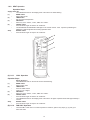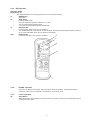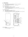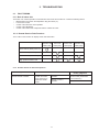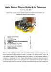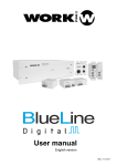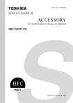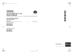
1
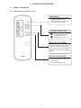
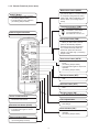
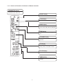
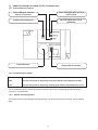
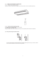
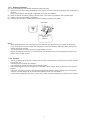
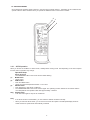
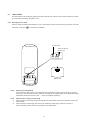
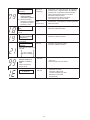
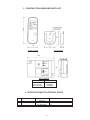
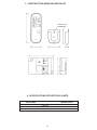
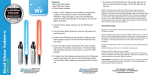
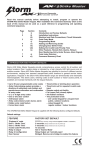
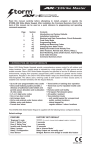
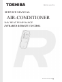
FILE NO. A90-9714
SERVICE MANUAL
AIR-CONDITIONER
RAV HEAT PUMP RANGE
INFRARED REMOTE CONTROL
Printed in UK Aug 1997 s
CONTENTS
1. OPERATION DESCRIPTION...................................................................................................................................3
2. TROUBLESHOOTING...........................................................................................................................................12
3. CONSTRUCTION VIEWS AND PARTS LIST..........................................................................................................17
4. SPECIFICATIONS OF ELECTRICAL PARTS..........................................................................................................17
SUMMARY
•
The infrared remote controller within this manual conforms with the protection requirements of European
Directives 89/ 336/EEC Electromagnetic Compatibility and 73/23/EEC Low Voltage.
-2-
1. OPERATION DESCRIPTION
1-1.
REMOTE CONTROLLER
1-1-1. Remote Functions (Cover closed)
ON/OFF Button
• Push this button to start operation.
(A receiving beep is heard)
• Push the button to stop operation.
(A receiving beep is heard)
Temperature button (TEMP)
The set temperature is
increased to a max 30ºC.
The set temperature is
decreased to a min of 17ºC.
Mode select button (MODE)
Push this button to select modes. Each
time you push the button, a mode is
selected in a sequence that goes from
AUTO, COOL, DRY,HEAT, FAN ONLY,
and back to AUTO. (A receiving beep is
heard).
Economy button (ECONO)
• Push this button to set the
economical operation mode of the
air conditioner.
(A receiving beep is heard)
-3-
1-1-2. Remote Functions (Cover Open)
Mode select button (MODE)
Push button to select modes. Each time
you push the button, a mode is selected
in a sequence that goes from AUTO,
COOL, DRY, HEAT, FAN ONLY, and
back to AUTO. (A receiving beep is
heard).
ON/OFF Button
• Push this button to start operation.
(A receiving beep is heard)
• Push the button to stop operation.
(A receiving beep is heard)
Temperature button (TEMP)
The set temperature is
increased to a max 30ºC.
The set temperature is
decreased to a min of 17ºC.
Infrared signal transmitter
Transmits the signal to the indoor unit
Fan speed button (FAN)
• Push this button to select fan speed.
• When you select AUTO, the fan
speed is automatically adjusted
according to the room temperature.
You can also manually select the
desired fan speed from the three
settings. Low, Med, High. (A receiving
beep is heard).
Auto louver button (AUTO)
• Push this button to operate the
louver.
(A receiving beep is heard).
• Push this button again to stop louver
operation.
(A receiving beep is heard).
Set louver button (SET)
• This button has no function on RAV
units.
Off timer button (OFF)
• Push this button to set the OFF
timer.
On timer button (ON)
• Push this button to set the ON timer.
Cover closed functions
• Push this button to show functions
as with the cover closed.
Time adjust button
• Rotate this to increase/decrease
time settings.
Function lock button (LOCK)
• Push this button to lock settings.
• Push this button again to cancel
lock function.
Cancel button (CNL)
• Push this button to cancel timer
operation.
(A receiving beep is heard).
Reserve button (RSV)
• Push this button to set timer
(A receiving beep is heard).
.
-4-
1-1-3. Names and Functions of Indicators on Remote Controller
TRANSMITTER display
Shows when the signal is being
transmitted to the undoor unit.
ON/OFF display
Shows if unit is enabled.
LOCK display
Shows if the Lock function is enabled.
MODE display
Shows the current mode of the unit,
AUTO, COOL, DRY, HEAT or FAN ONLY.
TEMP display
Shows the temperature setting of the
unit.
ECONOMY display
Shows if the economy mode is in
operation.
FAN display
Shows the units current fan speed
setting. AUTO, LOW, MED or HIGH.
CLOCK display
Shows the current time.
TIMER display
Shows the current timer ON and OFF
settings.
-5-
1-2. REMOTE RECEIVER FUNCTIONS (FITTED TO INDOOR UNIT)
1.2.1. Remote Receiver Features
Yellow LED lights when the
timer is in operation.
Green LED lights when unit is in
defrost mode.
Audible acknowledgement.
Red LED lights when unit is
operational.
Infrared Receiver
Remote Receiver Switch
1-2-2. Remote Receiver Switch
Remote control
The unit will be controlled by the Infrared Remote Control.
Auto
The unit will operate in temporary Auto mode with the set temperature at 24°c
Cool
The unit will operate in temporary Cooling mode with the set temperature at 17°c
The air conditioner can be controlled using this method in the event of misplacing the Infrared remote
controller or its malfunction.
1-2-3. Audible acknowledgement
The remote receiver acknowledges each transmission from the Infrared remote controller, with an audible
beep.
-6-
1-3.
HANDLING THE REMOTE CONTROLLER
1-3-1. Location of the Remote Controller
Operate the remote controller where its signals can reach the receiver on the air conditioner (within 7m)
1-3-2. Remote Controller Mounting bracket
A mounting bracket is supplied with the remote controller.
(1) Installing the mounting bracket
Install the bracket for the remote controller where the unit can be operated, with the remote in the bracket.
(2) Fitting and removing the remote controller
To mount, hold the remote controller parallel to the mounting bracket and push it in fully. To remove, slide the
remote controller upwards and out from the mounting bracket.
-7-
1-3-3. Replacing Batteries
The remote controller uses two alkaline dry batteries (LR03 AAA size).
(1) Remove the cover of the battery compartment at the back of the remote controller by sliding it out in the direction of
the arrow.
Remove used batteries and dispose of responsibly, then insert new batteries.
(2) Reset the remote controller by pressing the ACL button in the battery compartment, with a pointed object
(3) Replace the cover of the battery compartment.
(4) If remote controller fails to operate properly, repeat reseting by pressing ACC button.
ACL Button
Ensure the correct
polarity of
batteries
Notes:
• When replacing batteries, use correct type. Incorrect batteries may cause the remote controller to malfunction.
• If you do not use the remote controller over a long period, remove the batteries. Otherwise, battery leakage may
damage the remote controller.
• The average battery life during normal use is approximately one year.
• Replace the batteries when there is no receiving beep from the indoor unit or if the transmission indicator on the
remote control unit fails to show.
1-3-4. Cautions
•
•
•
•
•
•
The air conditioner will not operate if curtains, doors or other materials block the signal from the remote controller
to the indoor unit.
Protect the remote controller from moisture.
Do not expose the remote controller to direct sunlight or heat.
If the infrared signal receiver on the indoor unit is exposed to direct sunlight, the air conditioner may not function
properly.
If the room using the air conditioner has fluorescent lighting with electronic starters, signals may not be properly
received. If you are planning to use such fluorescent lamps, consult your local dealer.
If other electrical appliances react to the remote control, either move these appliances or consult your local dealer.
-8-
1-4 OPERATING MODES
Once selected the operating mode is stored in the unit's microcomputer memory. Thereafter, the air conditioner will
operate under the same conditions when you operate the ON/OFF button of the remote controller.
3
1
2
1-4-1. AUTO Operation
When you set the air conditioner in AUTO mode, it initially selects cooling mode. Then depending on the room temperature the mode of operation may change.
Operation Steps
(1)
•
(2)
•
•
(3)
•
•
Stop:
•
Note:
•
•
Supply Power On
The OPERATION LED on the remote receiver starts flashing.
MODE button
Select AUTO.
TEMP. button
Push the TEMP. button.
Select the required temperature between 17°C to 30°C.
ON/OFF button
Push this button to start the air conditioner.
The OPERATION LED on the remote receiver lights. The operating mode is selected in accordance with the
room temperature and operation starts after approximately 3 minutes.
ON/OFF button
Push this button again to stop the air conditioner.
If the AUTO mode is uncomfortable, you can select the desired conditions manually.
When you select the AUTO mode, you do not have to set the fan speed. The FAN speed display will show
AUTO and the fan speed will be automatically controlled.
-9-
1-4-2. HEAT Operation
Operation Steps
Supply Power On
The OPERATION LED on the display panel of the indoor unit starts flashing.
(1)
MODE button
•
Select HEAT mode.
(2)
TEMP button
•
Set the required temperature.
(3)
FAN button
•
Select any of the “AUTO”, “LOW”, “MED” and “HIGH”.
(4)
ON/OFF button
•
Push this button again to start the air conditioner.
•
The OPERATION and DEFROST LEDs light on the remote receiver. After a period of preheating the
DEFROST LED extinguishes and heating operation starts.
Stop:
ON/OFF button
•
Push this button again to stop the air conditioner.
4
1
2
3
(A) 1-4-3.
COOL Operation
Operation Steps
Stop:
•
Supply Power On
The OPERATION LED on the remote receiver starts flashing.
MODE button
Select COOL mode.
TEMP button
Push the TEMP. button.
Cooling 17°C or higher
FAN button
Select any of the “AUTO”, “LOW”, “MED” and “HIGH”.
ON/OFF button
Push this button again to start the air conditioner.
The OPERATION LED on the display panel of the lndoor unit lights. Operation starts after approximately 3
minutes.
ON/OFF button
Push this button again to stop the air conditioner.
(B) 1-4-4.
FAN ONLY Operation
(1)
•
(2)
•
•
(3)
•
(4)
•
•
•
The FAN ONLY mode does not control temperature. Therefore, perform only steps (1), (3) and (4) to
select this mode.
-10-
1-4-5. DRY Operation
Operation Steps
Supply Power On
The OPERATION LED on the display panel of the indoor unit starts flashing.
(1)
MODE button
•
Select DRY.
(2)
TEMP button
•
Push the TEMP. button.
•
Select the required temperature between 17°c to 30°c.
•
The fan speed indicator displays AUTO.
•
Low indoor fan speed will be selected automatically.
(3)
ON/OFF button
•
Push this button again to start the air conditioner.
•
The OPERATION LED on the remote receiver unit lights. Operation starts after approximately 3 minutes.
(If you select FAN ONLY mode, the unit will start immediately.)
Stop:
ON/OFF button
•
Push this button again to stop the air conditioner.
3
1
2
4
1-4-6.
ECONO. Operation
Econo can be selected in the AUTO, COOL and HEAT modes of operation. The fan speed selector
changes to AUTO. The air conditioner now operates in the economy mode.
1-4-7.
(4)
•
Louver Operation
AUTO Button
When this button is first pressed the louver will oscilate, its position can be fixed in a desired direction by
pressing the button again.
-11-
1-5.
TIMER OPERATION
1-5-1.
•
•
•
Setting the Clock
(1)
(2)
(3)
Push the clock set button in the battery compartment. The clock " : " starts flashing.
Rotate the TIME ADJUST dial to set the time
Press the RSV button when complete. The clock " : " remains constant.
1-5-2.
•
•
•
•
Setting the On time
(4)
(2)
(3)
Press the on button. The ON TIME " : " starts flashing.
Rotate the TIME ADJUST dial to set the time.
Press the RSV button when complete. The ON TIME " : " remains constant.
The yellow timer LED will Iluminate on the remote receiver and the air conditioner will begin to operate in
the previous set mode at the set on time.
1-5-3
•
•
•
•
Setting the Off time
(5)
(2)
(3)
Press the off Button. The OFF TIME " : " starts flashing.
Rotate the TIME ADJUST dial to set the time.
Press the RSV button when complete. The OFF TIME " : " remains constant.
The yellow timer LED will Iluminate on remote receiver and the Air conditioner will turn off at the set time.
4
5
1
2
6
3
1.5.4 Cancel Button
•
Push the CNL button to cancel the timer setting.
The yellow LED will extinguish.
-12-
2. TROUBLESHOOTING
2-1.
FAULT FINDING
2-1-1. Role of Indoor Unit.
The
•
•
•
•
•
indoor unit receives operation commands from the remote and monitors or controls the following factors.
Measurement of the return air temperature using the sensor (TA)
Louver motor control
Control of the indoor fan motor operation
Control of the LED display
Control of the outdoor unit compressor and the outdoor fan motor.
2-1-2. Remote Receiver Fault Functions
The L.E.D's on the receiver can display check code information.
RED
Operation LED
Flash (1Hz)
YELLOW
Timer LED
Flash (5Hz)
GREEN
Defrost LED
Flash (5Hz)
RED
Operation LED
Flash (5Hz)
Power Failure (When power on)
Service Mode (Selected)
Service Mode (Check code)
High pressure Switch Fault
2-1-3 Possible Causes of abnormal operation.
System
Indoor unit will not operate from
infrared Remote Controller.
Check
Isolate power supply
and then reconnect
before attempting to
operate the remote
control.
Remote control is not
possible.
Remote control is
possible.
-13-
Primary judgement
The indoor part (including the
remote control) is defective.
(Check batteries.)
O.K.
2-2.
CHECK CODES
The fault codes can be checked by putting the remote controller into service mode, and then checking the LED's
on the receiver according to the table in 2-1-2.
2-2-1. Selecting service mode
Push the button provided under the battery cover of the wireless remote control with a tip of pencil for more than
3 seconds. make sure “
” is showing on the display.
All clear button
All clear button
Switch for
for selecting
selecting
Switch
service mode
mode
service
ACL
CLOCK
ACL CLOCK
Battery
cover
Rear
bottom
cover
(Rear bottom of remote controller)
2-2-2.
Reverting to Normal Mode
Push the all clear button (ACL) on the rear bottom of the wireless remote control with a tip of pencil for
more than 3 seconds. Make sure the operation mode display, fan speed display, clock display and setting
temperature display are turned on and “ : ” of the clock display is flashing.
2-2-3.
1)
Cautions when carrying out servicing
After completion of servicing, always push the all clear (ACL) button to return the operation mode to the
normal mode.
After completion of servicing by the check code, isolate the power supply and then reconnect to
reset memorized contents of the microcomputer to the initial status.
2)
-14-
2-2-4. Check Code Diagnosis
The system can store and recall any of a predetermined selection of codes which can indicate associated electrical
or refrigeration faults.
Diagnosis by the check codes is conducted with procedures shown below.
a) Enter the service mode and make sure the off timer display of the remote control shows
“ ”.
b) Operate the “ON/OFF” key and make sure the timer lamp on the display section is flashing (5 Hz).
c) Next press the Temp
key and the displayed HEX code will increase by one. The receiver will then beep. When
the displayed check code matches the code on the indoor unit. The operation L.E.D will light and the HEX code
shown should be looked up in the following tables.
d) If other buttons on the remote are pressed in the service mode, the display will change as shown in the table below.
This option enables check code numbers to be quickly reached.
e) Fault codes can only be retrieved for the first unit if multiple units are wired in a group, therefore group operation is
not recommended.
Indication after operation
,,
“AUTO” LOUVER
The display code is increased by
16 e.g.
“SET” LOUVER
The display code is repeated
e.g.
,,
The display code is decreased by
"1".e.g.
,,
,,
,,
,,
(Down)
,,
TEMP.
,,
,,
The display code is increased by
"1".e.g.
,,
(Up)
,,
TEMP.
,,
,,
ON/OFF
,,
Operating key
2-2-5. List of Check Codes
DIAGNOSTIC FUNCTIONS
CHECK CODE
SYMPTON
ROOM TEMP.
SENSOR (TA).
Out of place, break,
short-circuit.
INDOOR
HEAT-EXCHANGER
SENSOR (TC).
JUDGEMENT AND ACTION
STATUS OF AIR
CONDITIONER
Operation
1. Check the indoor temp. sensor.
continuing
2. Check the indoor PC board.
Operation
continuing
1. Check the indoor heat-exchanger sensor.
2. Check the indoor PC board.
Operation
continuing
1. If outdoor unit does not work at all.
(1) Check the connecting cable correct wrong wiring.
(2) Check the outdoor PC board.
2. If operates normally.Between indoor terminal
plates 2 and 3, return signal is:
Available:
Check the indoor PC board.
Not available: Check the outdoor PC board.
Operation
continuing
1.
2.
3.
4.
5.
Out of place, break,
short-circuit.
RETURN SIGNAL
NOT COMING TO
INDOOR
1) Wrong wiring in connecting
cable (serial signal).
4-WAY VALVE
SYSTEM
1) Indoor heat-exchanger
temperature rises, after
starting cooling operation.
2) Indoor heat-exchanger
temperature drops after
starting heating operation.
-15-
Check the 4-way valve.
Check the 2-way valve and check valve.
Fault with indoor heat exchanger sensor.
Check the indoor PC board.
Two systems may be cross wired.
,,
,,
,,
,,
OTHER CYCLE
SYSTEM
1) Indoor heat exchange
temperature does not
change after starting
cooling/heating operation.
2) When transmitting
instruction for stopping
compressor by freeze
preventing control.
DEFROST SENSOR
(TE)
Operation
continuing
Outdoor unit
stops
(indoor fan L)
1. Compressor case thermostat, IOL, OL operation.
(contactor OFF, compressor stops: AH8 Models)
(contactor ON, compressor stops: AH Models)
2. Indoor heat-exchange sensor out of place.
3. Check the indoor PC board.
4. Check that service valves are OPEN.
5. Two systems may be cross wired.
1. Check the charged amount of refrigerant gas.
(Gas shortage → gas supplement, check for gas leaks)
2. Indoor fan locked.
Full stop
1. Check the defrosting sensor.
2. Check the outdoor PC board.
Full stop
1. Check the outdoor heat-exchanger sensor.
2. Check the outdoor PC board.
Out of place, break, shortcircuit.
OUTDOOR
HEAT-EXCHANGER
SENSOR (TL)
Out of place, break,
short-circuit.
1. Check the high pressure switch.
2. Check the outdoor PC board.
HIGH PRESSURE
Full stop
SWITCH
High pressure switch does
not reset.
5 sec in cooling
30 sec in heating
WRONG WIRING OF
REMOTE CONTROL
UNIT
Indoor unit does not
operate at all.
TD SENSOR
1. Check the wiring between remote control unit and
indoor unit.
2. Check the indoor unit PC board.
Full Stop
1.
2.
3.
4.
5.
Full stop
-16-
Check the TD sensor
Check the outdoor PCB
Possible refrigerant gas leak
Refrigerant cycle failure
Overload relay
3. CONSTRUCTION VIEWS AND PARTS LIST
101
160
Location holes
2-(4.5 x 9)
62
72
Remote controller
30
Remote Holder
100
60
30
Remote Receiver
Description
Remote controller
Holder, Remote
Remote Receiver
Part Number
43069666
43063253
43A69009
4. SPECIFICATIONS OF ELECTRICAL PARTS
No
PARTS NAME
1
2
Remote Control
Remote Receiver
3
Battery
TYPE
SPECIFICATIONS
WH-C2YE
XWS-DS5
Infrared remote control transmitter
Infrared remote control receiver
2 x LR03 (AAA)
-17-
1.5v
3. CONSTRUCTION VIEWS AND PARTS LIST
Location holes
2-(4.5 x 9)
30
4. SPECIFICATIONS OF ELECTRICAL PARTS
PARTS NAME
Remote Control
Remote Receiver
Battery
TYPE
WH-C2YE
XWS-DS5
2 x LR03 (AAA)
-18-
SPECIFICATIONS
Infra-red remote control transmitter
Infra-red remote control receiver
PORSHAM CLOSE, BELLIVER INDUSTRIAL ESTATE, PLYMOUTH, PL6 7DB, UK