1
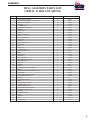
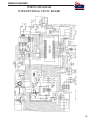
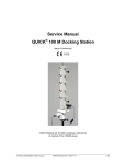
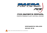
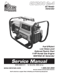
E300 3+2 Electric Welder Service Manual
Stick/Mig Capability
Welding Excellence
Modular Construction
Environment Protected
2,000 Watt AC Power for Tools
SVM_E300 3+2
SAFETY
Arc Welding Safety Precautions
PROTECT YOURSELF AND OTHERS FROM POSSIBLE SERIOUS INJURY OR DEATH. READ AND UNDERSTAND
BOTH THE SPECIFIC INFORMATION GIVEN IN THE OPERATING MANUAL FOR THE WELDER AND/OR OTHER
EQUIPMENT TO BE USED AS WELL AS THE FOLLOWING GENERAL INFORMATION.
1. HAVE ALL INSTALLATION, OPERATION, MAINTENANCE
AND REPAIR WORK performed only by qualified people.
2. ELECTRIC SHOCK can kill.
Protect yourself from possible dangerous electrical shock:
a. The electrode and work (or ground) circuits are
electrically "hot" when the welder is on. Never permit
contact between "hot" parts of the circuits and bare skin
or wet clothing. Wear dry, hole-free gloves to insulate
hands.
b.
Always insulate yourself from the work and ground by using dry
insulation. When welding in damp locations, on metal floors,
gratings or scaffolds, and when in positions such as sitting or
lying, make certain the insulation is large enough to cover your
full area of physical contact with work and ground.
Do not weld in locations near chlorinated hydrocarbon vapours
coming from degreasing, cleaning or spraying operations. The
heat and rays of the arc can react with solvent vapours to form
phosgene, a highly toxic gas, and other irritating products.
c.
Shielding gases used for arc welding can displace air and cause
injury or death. Always use enough ventilation, especially in
confined areas, to insure breathing air is safe.
d.
Read and understand the manufacturer's instructions for this
equipment and the consumables to be used, including the material safety data sheet (MSDS) and follow your employer's safety
practices.
e.
Also see item 9b.
4. ARC RAYS can injure eyes and burn skin.
a. Use a shield with the proper filter and cover plates to protect
your eyes from sparks and the rays of the arc when welding or
observing open arc welding. Headshield and filter lens should
conform to ANSI Z87. 1 standards.
c.
Always be sure the work cable makes a good electrical connection with the metal being welded. The connection should be as
close as possible to the area being welded.
d.
Ground the work or metal to be welded to a good
electrical ground.
b.
Use suitable clothing made from durable, flame-resistant material to protect your skin and that of your helpers from the arc rays.
Maintain the electrode holder, work clamp, welding cable and
welding machine in good, safe operating condition.
c.
Protect other nearby personnel with suitable nonflammable
screening and/or warn them not to watch the arc nor expose
themselves to the arc rays or to hot spatter or metal.
e.
f.
Never dip the electrode in water for cooling.
g.
Never simultaneously touch electrically "hot" parts of electrode
holders connected to two welders because voltage between the
two can be the total of the open circuit voltage of both welders.
h.
If using the welder as a power source for mechanized welding,
the above precautions also apply for the automatic electrode,
electrode reel, welding head, nozzle or semiautomatic welding
gun.
i.
When working above floor level, protect yourself from
a fall should you get a shock.
j.
Also see Items 6c and 8.
3. FUMES AND GASES can be dangerous to your health.
a. Welding may produce fumes and gases hazardous to health.
Avoid breathing these fumes and gases. When welding, keep
your head out of the fume. Use enough ventilation and/or
exhaust at the arc to keep fumes and gases away from the
breathing zone. When welding on galvanized, lead or cadmium
plated steel and other metals which produce toxic fumes, even
greater care must be taken.
2
b.
5. FIRE OR EXPLOSION can cause death or property damage.
a. Remove fire hazards well away from the area. If this is not possible cover them to prevent the welding sparks from starting a
fire. Remember that welding sparks and hot materials from
welding can easily go through small cracks and openings to
adjacent areas. Have a fire extinguisher readily available.
b.
Where compressed gases are to be used at the job site, special
precautions should be used to prevent hazardous situations.
Refer to "Safety in Welding and Cutting" (ANSI Standard 249.1)
and the operating information for the equipment being used.
c.
When not welding, make certain no part of the electrode circuit
is touching the work or ground. Accidental contact can cause
overheating and create a fire hazard.
d.
Do not heat, cut or weld tanks, drums or containers until the
proper steps have been taken to insure that such procedures will
not cause flammable or toxic vapours from substances inside.
They can cause an explosion even though they have been
"cleaned." For information purchase "Recommended Safe
Practices for the Preparation for Welding and Cutting of
Containers and Piping That Have Held Hazardous Substances.",
SAFETY
Highway, Arlington, VA 22202.
AWS F4.1-80 from the American Welding Society.
e.
Vent hollow castings or containers before heating, cutting or
welding. They may explode.
f.
Also see items 6c and 9c.
6. For Welding in General.
a. Droplets of molten slag and metal are thrown or fall from the
welding arc. Protect yourself with oil free protective garments
such as leather gloves, heavy shirt, cuffless trousers, high shoes
and a cap over your hair. Wear ear plugs when welding out of
position or in confined places. Always wear safety glasses when
in a welding area. Use glasses with side shields when near slag
chipping operations.
b.
c.
Keep all equipment safety guards, covers and devices in position
and in good repair. Keep hands, hair, clothing and tools away
from V-belts, gears, fans and all other moving parts when starting, operating or repairing equipment.
Be sure the work cable is connected to the work as close to the
welding area as practical. Work cables connected to the building
framework or other locations some distance from the welding
area increase the possibility of the welding current passing
through lifting chains, crane cables or other alternate circuits.
This can create fire hazards or overheat lifting chains or cables
until they fail.
7. For Gas-Shielded Arc Welding.
a. Use only compressed gas cylinders containing the correct shielding gas for the process used and properly operating regulators
designed for the gas and pressure used. All hoses, fittings, etc.
should be suitable for the application and maintained in good
condition.
b.
c.
Always keeps cylinders in an upright position securely chained
to an undercarriage or fixed support.
Cylinders should be located:
•
Away from areas where they may be struck or subjected to
physical damage.
•
A safe distance from arc welding or cutting operations and
any other source of heat, sparks, or flame.
d.
Never allow the electrode, electrode holder, or any other electrically "hot" parts to touch a cylinder.
e.
Keep your head and face away from the cylinder valve outlet
when opening the cylinder valve.
f.
Valve protection caps should always be in place and handtight
except when the cylinder is in use or connected for use.
g.
Read and follow the instructions on compressed gas cylinders,
associated equipment, and CGA publication P-1 "Precautions for
Safe Handling of Compressed Gases in Cylinders" available
from the Compressed Gas Association, 1235 Jefferson Davis
8. For Electrically Powered Equipment.
a. Turn off input power using the disconnect switch at the fuse box
before working on the equipment.
b.
Make the electrical installation in accordance with the
National Electrical Code, all local codes and the manufacturer's
recommendations.
c.
Properly ground the equipment in accordance with the National
Electrical Code and the manufacturer's recommendations.
9. For Engine Powered Equipment.
a. Turn the engine off before troubleshooting and maintenance
work unless the maintenance work requires it to be running.
b.
Operate the internal combustion engines in open, well ventilated
areas or vent the engine exhaust fumes outdoors.
c.
Do not add the fuel near an open flame, welding arc or when the
engine is running. Stop the engine and, if possible, allow it to
cool when refuelling to prevent spilled fuel from vaporizing on
contact with hot engine parts and igniting. Do not spill fuel
when filling tank. If fuel is spilled, wipe it up and do not start
engine until fumes have been eliminated.
d.
In some cases it may be necessary to remove safety guards to
perform required maintenance. Remove guards only when necessary and replace them when the maintenance requiring their
removal is complete. Always use the greatest care when working
near moving parts.
e.
Do not put your hands near the engine fan. Do not attempt to
override the governor or idler by pushing on the throttle control
rods while the engine is running.
f.
To prevent accidentally starting gasoline engines while turning
the engine or welding generator during maintenance work, disconnect the spark plug wires, distributor cap or magneto wire as
appropriate.
g.
To avoid scalding, do not remove the radiator pressure cap when
the engine is hot.
For more detailed information it is strongly recommended that you
purchase a copy of "Safety in Welding & Cutting - ANSI Standard
249.1" from the American Welding Society, P.O. Box 351040 Miami,
Florida 33135.
3
OPERATION
OPERATION
RATED OUTPUT
DC
For best operating characteristics and longest unit life, take care in
selecting an installation site. Avoid locations exposed to high
humidity, dust, high ambient temperature or corrosive fumes. Make
sure that the ventilator openings are not obstructed.
Amperes
Volts
Duty cycle
250
30
60%
• Connect welding machine to input voltage.
• Set INPUT CONTACTOR CONTROL ON/OFF SWITCH to ON
(UP) position.
• For LOCAL control, set the CURRENT CONTROL LOCAL/
REMOTE SWITCH to local (OFF) position. Adjust the welding
current by the CURRENT CONTROL potentiometer located on the
front panel.
• For REMOTE control, set the above switch to remote (ON)
position. Adjust the welding current by the potentiometer located in
the remote control.
For this mode of operation it will be necessary to use a Remote
Control Pendant plugged into the REMOTE CONTROL
RECEPTACLE.
• THE ARC FORCE CONTROL potentiometer varies the dynamic
slope of the volt-amp curves. It essentially charges the short-circuit
(arc) current and produces an increase of amperage when the arc is
shortened. Strong arc force is best suited for use with 6010
electrodes where there is a tendency for sticking, especially for
down hand welding.
MAINTENANCE
• Lubrication
The fan motor is permanently lubricated and will never need oil or
grease. No other points require lubrication.
• Cleaning
For uninterrupted satisfactory service from this welding machine, it
is necessary to keep the machine clean, dry and well ventilated.
At lease every two months or more often as necessary,wipe and
blow out all dirt from the machine's internal components with air
pressure of not over 25psi. Be sure to wipe the fan blades clean.
TECHNICAL DATA
DIMENSIONS
(LxWxH)
NET WEIGHT
DIMENSIONS
( in frame)
NET WEIGHT
(in frame)
CSA APPROVED
4
680 x 405 x 530 mm
26.8 x15.9 x20.9 in
117kg / 258 lbs
775 x 535 x 560 mm
30.5 x 21 x 22 in
130kg / 285 lbs
WELDING VOLTAGE AND CURRENT RANGE
Minimum current at 20Volt
Maximum current at 34Volt
20A
350A
INPUT 3 PHASE 60Hz - AT RATED LOAD
480V - AMPS - OPT
21
600V - AMPS - OPT
17
PRIMARY KW
1l
OPERATION
TABLE 2
RECOMMENDED COPPER CABLE SIZES
AT 60% DUTY CYCLE
Cable Sizes for Combined Length
of Electrode Plus Work Cable
Machine Size
in Amps
Up to 200 ft.
200 to 250 ft.
250
1
1/0
CONTROL OF WELDING CURRENT
There is one continuous current control which gives you complete
adjustment of current from minimum to maximum. For local control
make sure the remote control switch is in the "off' position. There is
also the possibility of installing a remote control. To control at a
distance the remote control switch must be in the "on" position.
There is also an Arc Force control which produces an increase of
amperage when the arc length is shortened, such as in a tight groove
or in pipe welding. This control provides more arc force and
eliminates the tendency of snuffing out the arc.
AUXILIARY POWER
Your E300 3+2 is equipped with AC auxiliary power.
The AC unit provides a Duplex 120Volt receptacle and 2KW of
maximum output. The output circuit is protected with circuit
breakers.
Power tools should always be grounded to the welded frame unless
they are protected by an approved system of double insulation.
MAINTENANCE
Have qualified personnel do the maintenance work. Turn the
engine off before working inside the machine. In some cases it
may be necessary to remove safety guards to perform required
maintenance. Remove guards only when necessary and replace
them when the maintenance requiring their removal is complete.
Always use the greatest care when working near moving parts.
Do not put your hands near the engine or generator fan. If a
problem cannot be corrected by following the instructions, take
the machine to the nearest RED-D-ARC location.
GENERAL INSTRUCTIONS
1. Blow out the welder and controls with an air hose at least once
every two months. In particularly dirty locations, this cleaning may
be necessary once a week. Use low pressure air to avoid driving
dirt into the insulation.
WARNING: Uncovered rotating equipment can be dangerous.
Use care so your hands, hair, clothing or tools do not
catch in the rotating parts.
5
CONTROL PANEL
CONTROL PANEL FEATURES
FRONT
REAR
21 - Voltage change cover
22 - Supply cable input
23 - Grounding screw
1 - On/Off Switch/Breaker 30 AMP
2 - Ground fault protector
3 - On light
4 - Stick/Tig mode select switch (optional)
5 - Remote current switch: Switch must be "off" when using machine with no remote control, "ON" when using with remote control.
6 - Welding current control: Use to adjust amperage desired.
7 - Remote current control receptacle
8 - "CC-CV" mode select switch: CC for all Stick and Tig applications CV for most semi automatic Mig applications
9 - Arc force control: To use arc force turn switch to "ON" position. Arc force is used mostly when using 6010, 7010 type electrodes,
especially for down hand. By using more arc force it makes the arc more forceful and prevents sticking. When a
smoother arc is desired , use less arc force.
10 - Arc force on/off switch
11 - Hot start on/off switch : When the switch is on, a boost of current is applied for a very short time when the arc is struck. This is used in
applications when arc starting is difficult. Do not use for Tig applications when soft start is desired.
12 - Positive electrode terminal
13 - Negative"MIG" terminal - has the least inductance and is recommended for MIG welding and arc air.
14 - Negative "stick" terminal - has the most inductance and is recommended for Stick and DC Tig welding.
15 - 15Amp circuit breaker
16 - 120 V single phase outlet
17 - I0Amp fuse for relay 120V
18 - lOAmp fuse for fan motor
19- Terminal board for wire feeder connections
20 - Serial number
6
TROUBLESHOOTING
WARNING:
• Have qualified personnel do the troubleshooting work. Turn the engine off before working inside the machine. In some
cases it may be necessary to remove safety guards to perform required maintenance. Remove guards only when necessary
and replace them when the maintenance requiring their removal is complete. Always use the greatest care when working
near moving parts.
• Do not put your hands near the engine fan. If a problem cannot be corrected by following the instructions, take the
machine-to the nearest Red-D-Arc Location.
TROUBLE
CAUSE
WHAT TO DO
1. Welder does not start
Note: It is normal for the
Fan not to run when machine
is cold.
No input power.
Check power switch.
Check lines voltage.
Check power supply and connections.
2. Welder has not output.
Remote control switch is in ‘ON’ position
with no remote OCV=OV.
Put remote switch in ‘OFF’ position.
3. Welder has abnormal arc.
Defective SCR.
Check OCV. If low check for defective SCRs.
Also check all connections.
Defective PC board.
Check OCV. If low check for defective PC board.
Also check all connections.
7
ASSEMBLY
MISCELLANEOUS ASSEMBLY
(SERIAL #s 0880 AND ABOVE)
8
ASSEMBLY
MISC. ASSEMBLY PARTS LIST
(SERIAL #s 0880 AND ABOVE)
ITEM
1
2
3
4
5
6
7
8
9
10
11
12
13
14
15
16
17
18
19
20
21
22
23
24
25
26
27
28
29
30
31
32
33
34
35
36
37
38
39
40
41
42
43
44
45
46
47
48
49
PART NAME & DESCRIPTION
Transformer assembly
Over load Thermostat 132 degrees C
Transformer Support
Insulator
Terminal Board
Over load 63 degrees C
Bracket
Front panel
Reactor
Resistor 100 Ohm
Rod
Frame Assembly
Base rails
Louvers
Circuit breaker 15 A
Base plate
Fan
Fan cover
Capacitor 4uF
Circuit breaker 10 A
Plate
Side Bracket
Heatsink
Lower Bracket
SCR diode IR 171RC40
Inside Bracket
Zenamic
Insulator
Shunt
Control panel frame assembly
Relay
Electronic panel GS9109b/c CC-CV
Front plate
Aluminum front name plate
Circuit breaker 30 A
Switch
Potentiometer 10K
Knob
Lifting support bracket
Stainless Steel Cover
Voltage change cover
Ground fault protector 25A
Rubber protection cover
On light
Connection Plate
Plate
Inductor
Rod
Lifting Hook
NO. REQ'D
1
1
1
13
1
1
1
1
1
1
1
1
2
3
1
1
1
1
1
2
1
2
4
1
6
2
6
3
1
1
1
1
1
1
1
4
2
2
1
1
1
1
1
1
3
1
1
8
1
PART NO.
15.077
14.277
14.886
11.707
17.516
14.285
16.967
16.968
16.648
12.776
12.777
16.969
15.081
15.082
13.640
17.504
16.080
14.878
363
13.728
17.505
15.086
14.752
15.083
905
14.754
12.736
954
14.899
14.893
14.765
16.970
14.895
17.823
15.084
910
12.993
14.293
15.085
14.901
16.972
356
13.410
11.221
15.419
17.506
14.993
622
16.973
9
ASSEMBLY
MISC. ASSEMBLY PARTS LIST CONTINUED
(SERIAL #s 0880 AND ABOVE)
ITEM
50
51
52
53
54
55
56
57
58
59
60
61
62
64
65
66
10
PART NAME & DESCRIPTION
CC-CV / Tig-Stick mode select switch (Optional lift arc)
Electronic panel lift arc GS9414 (Optional lift arc)
Capacitor 40uF 450V
Tie rod
Nut
Circuit breaker support
Left heatsink
Right heatsink
Washer
Rubber protection cover
Plate
Output connector plate
Female Euro connector
Overload Thermostat 100 degrees C
Plate
Grounding screw
NO. REQ'D
2
1
1
6
6
1
1
1
3
3
1
1
3
1
1
1
PART NO.
13.152
17.629
17.094
17.507
17.508
16.305
17.509
17.510
14.270
14.658
17.824
17.512
836
17.513
17.514
17.515
WIRING DIAGRAMS
PRIMARY WIRING DIAGRAM
11
WIRING DIAGRAMS
WIRING DIAGRAM
12
WIRING DIAGRAMS
WIRING DIAGRAM
WITH OPTIONAL TIG PC BOARD
13