1
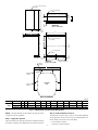
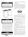
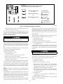
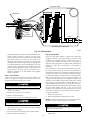
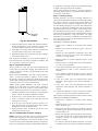
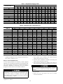
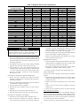
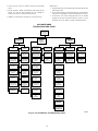
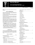
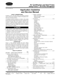
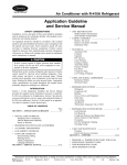
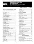
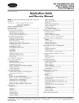
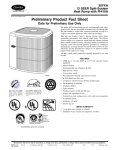
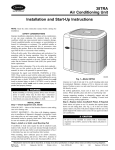
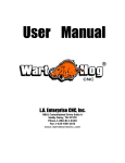
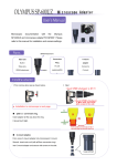
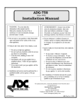
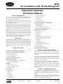
38TN
Air Conditioner with R134A Refrigerant
Application Guideline
and Service Manual
SAFETY CONSIDERATIONS
Service and repair of these units should be attempted only by
trained service technicians familiar with Carrier standard service
instruction and training material.
All equipment should be installed in accordance with accepted
practices and unit Installation Instructions, and in compliance with
all national and local codes.
Power should be turned off when servicing or repairing electrical
components. Extreme caution should be observed when troubleshooting electrical components with power on. Observe all warning notices posted on equipment and in instructions or manuals.
Refrigeration system contains refrigerant under pressure. Extreme
caution should be observed when handling refrigerants. Wear
safety glasses and gloves to prevent personal injury. During
normal system operation, some components are hot and can cause
burns. Rotating fan blades can cause personal injury. Appropriate
safety considerations are posted throughout this manual where
potentially dangerous techniques are addressed.
INTRODUCTION
This Application Guideline and Service Manual provides the
required system information necessary to install equipment in
low-ambient conditions, and service, repair, and maintain the
family of 38TN Air Conditioners with nominal capacities ranging
from 24,000 to 48,000 Btu’s. These air conditioners use R134A
refrigerant and operate at lower pressures than standard R22
systems.
TABLE OF CONTENTS
Page
SECTION 1—INSTALLATION GUIDELINE ......................1
SECTION 2—LOW-AMBIENT GUIDELINE ......................1
• Applicable Systems
• Field-Installed Accessories
• Accessory Information
SECTION 3—SERVICE MANUAL ........................................3
UNIT IDENTIFICATION .........................................................3
• Product Number Stamped on Unit Rating Plate
• Serial Number Identification
CABINET ....................................................................................3
• Remove Top Cover
• Remove Fan Motor Assembly
• Information Plate
ELECTRICAL ............................................................................4
•
•
•
•
•
•
Aluminum Wire
Contactor
Capacitor
PTC Devices
Cycle Protector
Crankcase Heater
• Time-Delay Relay (TDR)
• Pressure Switches
• Fan Motor
• Compressor Plug
• Low-Voltage Terminals
MILLENNIUM SCROLL COMPRESSOR ............................9
• Mechanical Failures
• Electrical Failures
• System Clean-Up After Burnout
• Compressor Removal and Replacement
REFRIGERATION SYSTEM ................................................11
• Refrigeration Cycle
• Leak Detection
• Brazing
• Service Valves
• AccuRater® (Bypass Type) Components
• Thermostatic Expansion Valve (TXV)
• Coil Removal
• Accumulator
• Contaminant Removal
• R134A Refrigerant System Charging
• Checking Charge
• Care and Maintenance
TROUBLESHOOTING CHART ...........................................18
SECTION 1—INSTALLATION GUIDELINE
Specifications for this unit in the RNC market require the outdoor
section, indoor section, refrigerant tubing sets, metering device,
and filter drier listed in Product Data Digest (PDD.) There can be
no deviation.
Specifications for this unit in the AOR market require change-out
of the total system, including the outdoor section, indoor section,
refrigerant tubing sets, metering device, and filter drier listed in
PDD. There can be no deviation.
The system can be applied in low-ambient conditions when
installed following the guidelines in Section 2 of this manual.
For long-line applications over 50 ft, consult the 38TN (R134A)
Residential Application Bulletin available from your local distributor. The R134A long-line application differs from R22 longline application.
SECTION 2—LOW-AMBIENT GUIDELINE
This guideline is for 38TN split-system products only. For
applications involving standard R22 single-speed products, refer to
Low-Ambient Guideline Residential Split-System Application
Bulletin.
This guideline explains the system changes and accessories required for any 38TN application having operating requirements
below 55°F outdoor ambient temperatures.
Manufacturer reserves the right to discontinue, or change at any time, specifications or designs without notice and without incurring obligations.
Book 1 1 2
PC 101
Catalog No. 513-829
Printed in U.S.A.
Form 38TN-1XA
Pg 1
3-94
Replaces: New
Tab 3a 5a 1a
7/
3
32″ x /8″
(5.56 x 9.53) SLOT
4 REQ'D
9/ ″ (3.45) DIA HOLE
64
2 REQ'D
H
3/ ″
8
6 1/16″
(154.0)
J
(9.6)
TYP
G
1/ ″
2
SUPPORT
(12.7)
TYP
MAT'L: 18 GA STEEL
16″
7/
C
(11.6)
TYP
A
E
1
/2″
(12.7)
TYP
9/ ″ (3.45) DIA HOLE
64
1 REQ'D
K
B
7/ ″
16
(11.6)
TYP
J
7/ ″ (5.56) DIA HOLE
32
3 REQ'D
1/ ″
4
1/ ″
4
M
(6.3)
TYP
L
(6.3)
TYP
D
BAFFLE
7/ ″ x 2″
32
(5.56 x 50.8) SLOT
MAT'L: 20 GA STEEL
SCREW
10 REQ'D
F
SUPPORT
4 REQ'D
OUTDOOR
UNIT
BAFFLE
2 REQ'D
BAFFLE ASSEMBLY
A93169
MODEL
38TN
UNIT SIZE
024
030
036, 048
A
21
21
21
B
32
32
32
C
11-3/16
11-13/16
11-3/16
D
23-3/4
29-3/4
35-3/4
E
24-1/2
30-1/2
36-1/2
F
42
42
42
G
23-11/16
29-11/16
35-11/16
H
24-7/16
30-7/16
36-7/16
J
23-5/8
29-5/8
35-5/8
K
19-11/16
19-11/16
19-11/16
L
11-7/8
14-7/8
17-7/8
M
6-11/16
6-11/16
6-11/16
Fig. 1—Wind Baffle Construction/Dimensions
NOTE: The PDD literature for the outdoor unit must be used in
conjunction with this guideline.
Step 1—Applicable Systems
The 38TN outdoor unit with approved indoor combination listed in
the outdoor unit PDD can be modified for low-ambient operation.
2
Step 2—Field-Installed Accessories
The following accessories may or may not be required depending
on the application. Some accessories may be standard features on
certain outdoor units. Refer to the 38TN PDD.
• Low-Ambient Controller
• Compressor Crankcase Heater
•
Evaporator Freeze Thermostat
•
Winter Start Control
•
Wind Baffle
•
Start Components
•
Ball Bearing Motor
Improper installation, adjustment, alteration, service, maintenance, or use can cause explosion, fire, electrical shock, or
other conditions which may cause personal injury, death, or
property damage. Consult a qualified installer, service agency
or your distributor or branch for information or assistance.
The qualified installer or agency must use factory-authorized
kits or accessories when modifying this product.
Step 3—Accessory Information
LOW-AMBIENT CONTROLLER — Required on all applications. There are 2 low-ambient controllers available from RCD.
32LT660004
P251-0083
UNIT IDENTIFICATION
Step 1—Product Number Stamped on Unit Rating Plate
Motor Master: Used on 208/230-v systems.
Requires ball bearing motor.
The unit product number has 16 positions containing groups of
numbers, letters, and dashes that indicate specific information
about the unit. Listed below is the breakdown of the 16 positions.
Solid-State Head Pressure Control:
Requires ball bearing motor in full modulation mode
only. See Installation Instructions for set-up on sleeve
bearing motor application.
Positions 1 and 2 —Type of Product
COMPRESSOR CRANKCASE HEATER — Required on all applications. The crankcase heater is purchased from Finished
Goods. See PDD for accessory part no.
Example: 38 — Split-System Air Conditioner or Heat Pump
Positions 3, 4, and 5—Model Letters
Identifies a specific product model. In some instances the fifth
position will be a dash (-).
EVAPORATOR FREEZE THERMOSTAT — Required on all
applications. The evaporator freeze thermostat is purchased from
Finished Goods. See PDD for accessory part no.
Position 6, 7, and 8—Nominal Cooling Capacity (in thousands
Btuh)
WINTER START CONTROL — Required on all applications
which have factory-supplied or field-installed low-pressure switch.
The winter start control is purchased from Finished Goods. See
PDD for accessory part no.
Example: 036 = 36,000 Btuh or 3-ton capacity.
Position 9, 10, and 11—Not Used
These positions will contain dashes (---).
WIND BAFFLE — Use only on installations where high prevailing winds are prevalent and where outdoor ambient temperatures
of less than 0°F could occur during unit operation. Wind baffles
are field fabricated. For construction details see Fig. 1.
Position 12—Electrical Supply
START COMPONENTS — The 38TN unit is equipped with a
Millennium scroll compressor specifically designed for use with
R134A refrigerant. A PTC soft start assist is factory installed. No
other start assist is required.
New units have 0. As major component variations occur, such as
compressor, fan motor, coil circuiting changes, etc., the change is
indicated by increasing this digit in increments of 1.
BALL BEARING MOTOR — Required on all applications using
motor master controller and solid state head pressure control when
used in full modulation mode. The 024 through 036 sizes require
motor HC38GE230, and the 048 size requires motor HC40GE230.
On split-system products, this digit will be 0.
3 = 230 or 208-230 or 208/230, 1 Phase, 60 Hertz
Position 13—Series
Position 14—Packaging
Positions 15 and 16—Not Used
These positions will contain dashes (--).
Step 2—Serial Number Identification
SECTION 3—SERVICE MANUAL
The unit serial number has 10 positions containing groups of
numbers and a letter that indicates specific information about the
unit. Listed below is the breakdown of the 10 positions.
SAFETY CONSIDERATIONS
Service and repair of these units should be attempted only by
trained service technicians familiar with Carrier standard service
instructions and training material.
Positions 1 and 2—Week of Manufacture
All equipment should be installed in accordance with accepted
practices, unit Installation Instructions, and in compliance with all
national and local codes.
01—First week of a year
52—Last week of a year
Power should be turned off when servicing or repairing electrical
components. Extreme caution should be observed when troubleshooting electrical components with power on. Observe all warning notices posted on equipment and in instructions or manuals.
Example:
Example:
Positions 3 and 4—Year of Manufacture
94—1994
Position 5—Manufacturing Site
Example:
Refrigeration system contains refrigerant under pressure. Extreme
caution should be observed when handling refrigerants. Wear
safety glasses and gloves to prevent personal injury. During
normal system operation, some components are hot and can cause
burns. Rotating fan blades can cause personal injury. Appropriate
safety considerations are posted throughout this manual where
potentially dangerous techniques are addressed.
E—Collierville
Positions 6 through 10—Serial Number
CABINET
Certain maintenance routines and repairs require removal of
cabinet panels. (See Fig. 2.)
Step 1—Remove Top Cover
1. Turn off all power to outdoor and indoor units.
INTRODUCTION
2. Remove access panel.
This service manual enables a service technician to service, repair,
and maintain the family of 38TN Air Conditioners.
3. Remove information plate.
3
SEFL JOSD
J SEFL
JOSDJ
SEFL JOSD
J SEFL
JOSDJ
SEFL JOSD
J SEFL
JOSDJ
SEFL JOSDJ
SEFL JOSDJ SEFL JOSDJ
SEFL JOSDJ SEFL JOSDJ PAASFLDLKREW
ATC
SEFL JOSDJ SEFL JOSDJ
UTUHD
SEFL JOSDJ SEFL JOSDJC
SEFL JOSDJ SEFL JOSDJH MD
SEFL JOSDJ R ITYALK
A88411
Fig. 3—Information Plate
A92446
Fig. 2—Basic Cabinet Design
ELECTRICAL
4. Disconnect fan motor wires and cut wire ties. Remove wires
from control box. Refer to unit wiring label.
5. Remove screws holding top cover to coil grille and corner
posts.
6. Lift top cover from unit.
7. Reverse sequence for reassembly.
Step 2—Remove Fan Motor Assembly
1. Perform items 1 through 6 above.
2. Remove nuts holding fan motor top cover.
3. Remove motor and fan blade assembly.
4. Reverse sequence for reassembly.
5. Prior to applying power, check that fan rotates freely.
Step 3—Information Plate
The information plate is secured to the front of the control box and
provides the control box cover. (See Fig. 3.) This plate also
provides a surface to attach the wiring schematic, superheat
charging tables with instructions, and warning labels. The plate has
2 tabs on the top edge that are bent down at slightly more than 90°.
When the information plate is removed, these tabs can be inserted
into 2 mating slots in the bottom front edge of the control box and
the plate will hang down forming a lower front panel. (See Fig. 4.)
This is convenient when access to the controls is required while the
unit is operating. The information plate on the small size casing
completely covers the opening below the control box. On larger
models the information plate may not cover the entire opening. In
this instance, the top cover can be removed and placed on its side
to cover the additional space.
Exercise extreme caution when working on any electrical
components. Shut off all power to system prior to troubleshooting. Some troubleshooting techniques require power to
remain on. In these instances, exercise extreme caution to
avoid danger of electrical shock. ONLY TRAINED SERVICE PERSONNEL SHOULD PERFORM ELECTRICAL
TROUBLESHOOTING.
Troubleshooting chart for the 38TN Air Conditioner units is
provided at the back of this manual. It will enable the service
technician to use a systematic approach to locating the cause of a
problem and correcting system malfunctions. (See Fig. 21.)
Step 1—Aluminum Wire
Aluminum wire may be used in the branch circuit (such as the
circuit between the main and unit disconnect), but only
copper wire may be used between the unit disconnect and the
unit.
Whenever aluminum wire is used in the branch circuit wiring with
this unit, adhere to the following recommendations.
Connections must be made in accordance with the National
Electrical Code (NEC), using connectors approved for aluminum
wire. The connectors must be UL approved (marked Al/Cu with
the UL symbol) for the application and wire size. The wire size
selected must have a current capacity not less than that of the
copper wire specified, and must not create a voltage drop between
the service panel and the unit in excess of 2 percent of the unit
rated voltage. To prepare the wire before installing the connector,
all aluminum wire must be "brush-scratched" and coated with a
corrosion inhibiter such as Pentrox A. When it is suspected that the
connection will be exposed to moisture, it is very important to
cover the entire connection completely to prevent an electrochemical action that will cause the connection to fail very quickly. Do
not reduce the effective size of wire, such as cutting off strands so
that the wire will fit a connector. Proper size connectors should be
4
SEFL
SEFL
SEFL
JOSD
J SE
FL JO
SEFL
SDJ
JOSD
J SE
FL JO
SEFL
SDJ
JOSD
J SE
FL JO
SDJ
SEFL
JOSD
J SE
FL JO
SDJ
J SE
FL JO
SDJ
J SE
FL JO
SDJ
JOSD
JOSD
SEFL
JOSDJ
SEFL
JOSDJ SEFL JOS
SEFL
JOSDJ SEFL JOSDJ PAASFLD
SEFL
LKREW
JOSDJ SEFL JOSDJ ATC
SEFL
JOSDJ SEFL JOSDJ UTUHD
SEFL
JOSDJ SEFL JOSDJC MD
DJH
SEFL
JOSDJ R ITYALK
A88412
SEFL
JOSDJ
SEFL
JOSDJ SEFL JOS
SEFL
JOSDJ SEFL JOSDJ PAASFL
SEFL
DLKREW
JOSDJ SEFL JOSDJ ATC
SEFL
JOSDJ SEFL JOSDJ UTUHD
SEFL
JOSDJ SEFL JOSDJC MD
DJH
SEFL
JOSDJ R ITYALK
A88413
Fig. 4—Information Plate Removed/Installed Below Control Box
used. Check all factory and field electrical connections for
tightness. This should also be done after the unit has reached
operating temperatures, especially if aluminum conductors are
used.
Step 2—Contactor
The contactor provides a means of applying power to unit using
low voltage (24v) from transformer in order to power the contactor
coil. (See Fig. 5.) Depending on unit model, you may encounter
single-, double-, or triple-pole contactors to break power. Exercise
extreme caution when troubleshooting as 1 side of the line may be
electrically energized.
The contactor coil is powered by 24vac. If contactor does not
operate:
1. With power off, check whether contacts are free to move.
Check for severe burning or arcing on contact points.
2. With power off, use ohmmeter to check for continuity of coil.
Disconnect leads before checking. A low resistance reading is
normal. Do not look for a specific value, as different part
numbers will have different resistance values.
3. Reconnect leads and apply low-voltage power to contactor
coil. This may be done by leaving high-voltage power to
outdoor unit off and turning thermostat to cooling. Check
voltage at coil with voltmeter. Reading should be between 20v
and 30v. Contactor should pull in if voltage is correct and coil
is good. If contactor does not pull in, replace contactor.
4. With high-voltage power off and contacts pulled in, check for
continuity across contacts with ohmmeter. A very low or 0
resistance should be read. Higher readings could indicate
burned or pitted contacts which may cause future failures.
A88350
Fig. 5—Contactor
5
Step 3—Capacitor
3. Remove any capacitor that shows signs of bulging, dents, or
leaking. Do not apply power to a defective capacitor as it may
explode.
Capacitors can store electrical energy when power is off.
Electrical shock can result if you touch the capacitor terminals and discharge the stored energy. Exercise extreme
caution when working near capacitors. With power off,
discharge stored energy by shorting across the capacitor
terminals with a 15,000-ohm, 2-watt resistor.
Step 4—PTC Devices
Sometimes under adverse conditions, a standard run capacitor in a
system is inadequate to start compressor. In these instances, a start
assist device is used to provide an extra starting boost to compressor motor. This device is called a positive temperature coefficient
(PTC) or thermistor. (See Fig. 7.) It is a resistor wired in parallel
with the run capacitor. As current flows through the PTC at
start-up, it heats up. As PTC heats up, its resistance increases
greatly until it effectively lowers the current through itself to an
extremely low value. This, in effect, removes the PTC from the
circuit.
NOTE: If bleed resistor is wired across start capacitor, it must be
disconnected to avoid erroneous readings when ohmmeter is
applied across capacitor. (See Fig. 6.)
12.5-22.5 OHMS
12.5 OHM
(BEIGE COLOR)
A94007
Fig. 7—PTC Device
After system shutdown, resistor cools and resistance value returns
to normal until next time system starts. Thermistor device is
adequate for most conditions, however, in systems where off cycle
is short, device cannot fully cool and becomes less effective as a
start device. It is an easy device to troubleshoot. Shut off all power
to system.
A94006
Fig. 6—Capacitor
Check thermistor with ohmmeter as described below. Shut off all
power to unit. Remove PTC from unit. Wait at least 10 minutes for
PTC to cool to ambient temperature.
Always check capacitors with power off. Attempting to
troubleshoot a capacitor with power on can be dangerous.
Defective capacitors may explode when power is applied.
Insulating fluid inside is combustible and may ignite, causing
burns.
Measure resistance of PTC with ohmmeter as shown in Fig. 7.
The cold resistance (RT) of any PTC device should be approximately 100-180 percent of device ohm rating.
12.5-ohm PTC = 12.5-22.5 ohm resistance - beige color
If PTC resistance is appreciably less than rating or more than 200
percent higher than rating, device is defective.
Capacitors are used as a phase-shifting device to aid in starting
certain single-phase motors. Check capacitors as follows.
Use of start capacitor and relay IS NOT RECOMMENDED on
units equipped with a Millennium scroll compressor.
1. After power is off, discharge capacitors as outlined above.
Disconnect capacitor from circuit. Put ohmmeter on R X 10k
scale. Using ohmmeter, check each terminal to ground (use
capacitor case). Discard any capacitor which measures 1/2
scale deflection or less. Place ohmmeter leads across capacitor
and place on R X 10k scale. Meter should jump to a low
resistance value and slowly climb to higher value. Failure of
meter to do this indicates an open capacitor. If resistance stays
at 0 or a low value, capacitor is internally shorted.
Step 5—Cycle Protector
Solid-state cycle protector protects unit compressor by preventing
short cycling. After a system shutdown, cycle protector provides
for a 5 ± 2-minute delay before compressor restarts. On normal
start-up, a 5-minute delay occurs before thermostat closes. After
thermostat closes, cycle protector device provides a 3-sec delay.
(See Fig. 8, 9, and 10.)
2. Capacitance testers are available which will read value of
capacitor. If value is not within ± 10 percent value stated on
capacitor, it should be replaced. If capacitor is not open or
shorted, the capacitance value is calculated by measuring
voltage across capacitor and current it draws.
Cycle protector is simple to troubleshoot. Only a voltmeter capable
of reading 24v is needed. Device is in control circuit, therefore,
troubleshooting is safe with control power (24v) on and highvoltage power off.
With high-voltage power off, attach voltmeter leads across T1 and
T3, and set thermostat so that Y terminal is energized. Make sure
all protective devices in series with Y terminal are closed.
Voltmeter should read 24v across T1 and T3. With 24v still
applied, move voltmeter lead from T1 terminal to T2 terminal
across T2 and T3. After 5 ± 2 minutes, voltmeter should read 24v,
indicating control is functioning normally. If no time delay is
encountered or device never times out, change control.
Exercise extreme caution when taking readings while power
is on. Electrical shock can cause personal injury or death.
Use following formula to calculate capacitance:
2650 X amps
Capacitance (mfd) =
volts
6
3
SEC
OPERATING
TIME
5 MIN
T1
_
T2
T2
T1
T3
BLK DENOTES CLOSED CONTACTS
HN67ZA008
HN67ZA008
A94005
A94009
Fig. 8—Cycle Protector Device
Fig. 9—Cycle Protector Sequence
CUT YELLOW WIRE
BETWEEN CONTACTOR AND
LOW-PRESSURE SWITCH
Y
YEL
SAFETY
CONTROL
TERMINAL
BOARD
CONNECTION
YEL
YEL
YEL
T1
C
BRN
TERMINAL
BOARD
CONNECTION
VIO
LOGIC
T3
C
BLK
T2
A88415
Fig. 10—Cycle Protector Wiring
CH
Step 6—Crankcase Heater
Crankcase heater is a device for keeping compressor oil warm. By
keeping oil warm, refrigerant does not migrate to and condense in
compressor shell when the compressor is off. This prevents
flooded starts which can damage compressor.
11
On units that have a single-pole contactor, the crankcase heater is
wired in parallel with the contactor contacts and in series with the
compressor. (See Fig. 11.) When the contacts open, a circuit is
completed from the line side of the contactor, through the
crankcase heater, through the run windings of the compressor, and
to the other side of the line. When the contacts are closed, there is
no circuit through the crankcase heater because both leads are
connected to the same side of the line. This allows the heater to
operate when the system is not calling for cooling. The heater
does not operate when the system is calling for cooling.
21
A94008
Fig. 11—Wiring for Single-Pole Contactor
With power off and heater leads disconnected, check across leads
with ohmmeter. Do not look for a specific resistance reading.
Check for resistance or an open circuit. Change heater if an open
circuit is detected.
The crankcase heater is powered by high-voltage power of unit.
Use extreme caution troubleshooting this device with power on.
The easiest method of troubleshooting is to apply voltmeter across
crankcase heater leads to see if heater has power. Do not touch
heater. Carefully feel area around crankcase heater. If warm,
crankcase heater is probably functioning. Do not rely on this
method as absolute evidence heater is functioning. If compressor
has been running, the area will still be warm.
Step 7—Time-Delay Relay (TDR)
The TDR is a solid-state controlled recycle delay timer which
keeps the indoor blower operating for 90 sec after thermostat is
satisfied. This delay enables the blower to remove residual cooling
in the coil after compression shutdown, thereby improving the
efficiency of the system. The sequence of operation is that on
closure of the wall thermostat and at the end of a fixed on delay of
7
1 sec, the fan relay is energized. When the thermostat is satisfied,
an off delay is initiated. When the fixed delay of 90 ± 20 sec is
completed, the fan relay is de-energized and fan motor stops. If the
wall thermostat closes during this delay, the TDR is reset and the
fan relay remains energized. The TDR is a 24-v device that
operates within a range of 15v to 30v and draws about .5 amps.
A
If the blower runs continuously instead of cycling off when the fan
switch is set on AUTO, the TDR is probably defective and must be
replaced.
Step 8—Pressure Switches
INVIROFLOW TOP
A94066
The low-pressure switch used on the 38TN unit is the switch
normally used in heat pump applications. The standard air conditioner low-pressure switch is NOT used.
Fig. 12—Fan Position
provided.
For suspected electrical failures, check for loose or faulty electrical
connections, or defective fan motor capacitor. Fan motor is
equipped with thermal overload device in motor windings which
may open under adverse operating conditions. Allow time for
motor to cool so device can reset. Further checking of motor can
be done with an ohmmeter. Set scale on R X 1 position, and check
for continuity between 3 leads. Replace motors that show an open
circuit in any of the windings. Place 1 lead of ohmmeter on each
motor lead. At same time, place other ohmmeter lead on motor
case (ground). Replace any motor that shows resistance to ground,
arcing, burning, or overheating.
Pressure switches are protective devices wired into control circuit
(low voltage). They shut off compressor if abnormally high or low
pressures are present in the refrigeration circuit. Depending on unit
model, you may find a low- and/or high-pressure switch in system.
LOW-PRESSURE SWITCH — The low-pressure switch is located on suction line and protects against low suction pressures
caused by such events as loss of charge, low airflow across indoor
coil, dirty filters, etc. It opens on a pressure drop at about 7 psi. If
system pressure is above this, switch should be closed. To check
switch, turn off all power to unit, disconnect leads on switch, and
apply ohmmeter leads across switch. You should have continuity
on a good switch. Because these switches are attached to refrigeration system under pressure, it is not advisable to remove this
device for troubleshooting unless you are reasonably certain that a
problem exists. If switch must be removed, remove and recover all
system charge so that pressure gages read 0 psi.
Step 10—Compressor Plug
The compressor electrical plug provides a quick-tight connection
to the compressor terminals. The plug completely covers the
compressor terminals and the mating female terminals are completely encapsulated in the plug. Therefore, the terminals are
isolated from any moisture so corrosion and resultant pitted or
discolored terminals are reduced. The plug is oriented to the relief
slot in the terminal box so the cover cannot be secured if wires are
not positioned in slot, assuring correct electrical connection at the
compressor. The plug can be removed by simultaneously pulling
while "rocking" the plug. However, these plugs are specialized and
vary in terminal orientation. Therefore, plugs can be used on only
the specific compressor. Fig. 13 shows compressor plug configuration for the Millennium scroll compressor. The configuration
around the fusite terminals is the outline of the terminal covers.
The slot through which the wires of the plug are routed is oriented
on the bottom and slightly to the left. The correct plug can be
connected easily to the compressor terminals and plug wires routed
easily through the slot in the terminal cover.
Wear safety glasses and gloves when working with refrigerants.
Apply heat with torch to solder joint and remove switch. Wear
safety glasses when using torch. Have quenching cloth available.
Oil vapor in line may ignite when switch is removed.
Braze in 1/4-in. flare fitting and screw on replacement pressure
switch.
HIGH-PRESSURE SWITCH — The high-pressure switch is located on liquid line, and protects against high discharge pressures
caused by such events as overcharge, condenser fan motor failure,
system restriction, etc. It opens on pressure rise at about 425 psi.
If system pressures go above this setting during abnormal conditions, the switch opens. Do not attempt to simulate these system
abnormalities as high pressures pose a serious safety hazard.
High-pressure switch is also checked with an ohmmeter similar to
checking low-pressure switch. If system pressure is below 425 psi,
the switch shows continuity. It is replaced in the same manner as
low-pressure switch. Observe all safety precautions.
Step 9—Fan Motor
CARLYLE
LEAD 1
BLK
C
S
C
R S
R
LEAD 3
BLUE
Fan motor rotates the fan blade that either draws or blows air
through outdoor coil to perform heat exchange. Motors are totally
enclosed to increase reliability. This also eliminates need for rain
shield. For the correct position of the fan blade assembly, see Fig.
12. The A dimension indicated in Fig. 12 equals 6-1/8 in.
LEAD 2
YEL
A94011
Fig. 13—Compressor Plug
Step 11—Low-Voltage Terminals
Turn off all power to unit before servicing or replacing fan
motor. Be sure unit main power switch is turned off. Failure
to do so may result in electric shock, death, or injury from
rotating fan blade.
The
low-voltage
terminal
designations
and
their
description/function are used on all split-system condensers.
G—Energizes indoor blower circuit.
R—Energizes 24-v power from transformer (red).
The bearings are permanently lubricated, therefore, no oil ports are
8
Y—Energizes contactor for cooling.
Step 1—Mechanical Failures
C—Common side of transformer (blk).
A compressor is a mechanical pump driven by an electric motor
contained in a welded or hermetic shell. In a mechanical failure,
motor or electrical circuit appears normal, but compressor does not
function normally.
MILLENNIUM SCROLL COMPRESSOR
(R134A REFRIGERANT)
The compressor used in this product is specifically designed for
use with R134A refrigerant and cannot be interchanged.
The compressor is an electrical (as well as mechanical) device.
Exercise extreme caution when working near compressors. Power
should be shut off, if possible, for most troubleshooting techniques. Refrigerants in system present other safety hazards.
To avoid personal injury or death, do not supply power to unit
with compressor terminal box cover removed.
Exercise extreme caution when reading compressor currents
when high-voltage power is on. Correct any of the problems
described below before installing and running a replacement
compressor. Wear safety glasses and gloves when handling
refrigerants.
Always wear safety glasses and gloves when handling refrigerants.
The scroll compressor pumps refrigerant through the system by the
interaction of a stationary and an orbiting scroll. (See Fig. 14.) The
scroll compressor has no dynamic suction or discharge valves, and
it is more tolerant of stresses caused by debris, liquid slugging, and
flooded starts.
LOCKED ROTOR — In this type of failure, compressor motor
and all starting components are normal. When compressor attempts to start, it draws locked rotor current and cycles off on the
internal protection. Locked rotor current is measured by applying
a clamp-on ammeter around common (blk) lead of the compressor.
Current drawn when it attempts to start is then measured. Locked
rotor amp (LRA) value is stamped on compressor nameplate.
Scroll Gas Flow
Compression in the scroll is
created by the interaction of
an orbiting spiral and a
stationary spiral. Gas enters
an outer opening as one of the
spirals orbits.
2
The open passage is sealed off
as gas is drawn into the spiral.
4
By the time the gas arrives at
the center port, discharge
pressure has been reached.
If compressor draws locked rotor amps and all other external
sources of problems have been eliminated, compressor must be
replaced. Because compressor is a sealed unit, it is impossible to
determine exact mechanical failure. However, complete system
should be checked for abnormalities such as incorrect refrigerant
charge, restrictions, insufficient airflow across indoor or outdoor
coil, etc., which could be contributing to the failure.
1
RUNS, DOES NOT PUMP — In this type of failure, compressor
motor runs and turns compressor, but compressor does not pump
the refrigerant. A clamp-on ammeter on common leg shows a very
low current draw, much lower than rated load amp (RLA) value
stamped on compressor nameplate. Because no refrigerant is being
pumped, there is no return gas to cool compressor motor. It
eventually overheats and shuts off on its internal protection.
3
As the spiral continues to orbit,
the gas is compressed into an
increasingly smaller pocket.
NOISY COMPRESSOR — Noise may be caused by a variety of
internal problems such as loosened hardware, broken mounting
springs, etc. System problems such as an overcharged compressor
(especially at start-up) or too much oil in compressor may also
cause excessive noise. Excess oil in compressor is encountered
only after a replacement compressor has been added without
purging oil from previous compressor. As the new compressor
pumps, excess oil in system returns and adds to volume already
present, causing noise.
5
Actually, during operation, all
six gas passages are in various
stages of compression at all
times, resulting in nearly continuous suction and discharge.
COMPRESSOR LEAKS
Use safety glasses and gloves when handling refrigerants.
A90198
Fig. 14—Scroll Compressor Refrigerant Flow
Sometimes a leak is detected at weld seam around girth of
compressor, or at a fitting that joins compressor shell. Many of
these leaks can be repaired and the compressor saved if correct
procedure is followed.
The Millennium scroll has a shutdown flapper valve located
between the scroll plates and the discharge head. The discharge
head remains under pressure during shutdown and requires a
factory supplied PTC start thermistor.
1. Turn off all power to unit.
The Millennium scroll compressor uses Mobil 68POE, the only oil
recommended for oil recharge. Oil recharge for the Millennium
SCD compressor is 34 fl. oz. and the SRD compressor is 52 fl. oz.
2. Remove and recover all refrigerant from system so that gage
pressures are 0 psi.
Compressor failures are classified in 2 broad failure categories;
mechanical and electrical. Both types are discussed below.
4. Apply flux and repair joint with silver solder. Do not use low
temperature solder such as 50-50.
3. Clean area around leak to bare metal.
9
(EXAMPLE)
TO DETERMINE INTERNAL CONNECTIONS OF SINGLEPHASE MOTORS (C,S,R) EXCEPT SHADED-POLE
?
?
DEDUCTION:
POWER OFF!
?
1
3
(GREATEST RESISTANCE)
5.8Ω (OHM)
RUN WINDING (R)
START WINDING (S)
OHMMETER
0-10Ω SCALE
2
3
(SMALLEST RESISTANCE)
0.6Ω
2 IS COMMON (C)
BY ELIMINATION
1
2
(REMAINING RESISTANCE)
5.2Ω
2 IS COMMON,
THEREFORE, 1 IS
1
5.2Ω
1
2
0.6Ω
5.8Ω
START WINDING (S)
2
3
3
3 IS RUN WINDING (R)
A88344
Fig. 15—Identifying Internal Connections
help determine the problem. First, all possible external causes
should be eliminated, such as overloads, improper voltage, pressure equalization, defective capacitor(s), relays, wiring, etc. Compressor has internal line break overload, so be certain it is closed.
5. Clean off excess flux, check for leaks, and apply paint over
repaired area to prevent corrosion.
Do not use this method to repair a compressor leak due to severe
corrosion. Never attempt to repair a compressor leaking at electric
terminals. This type of failure requires compressor replacement.
OPEN CIRCUIT
Step 2—Electrical Failures
To determine if any winding has a break in the internal wires and
current is unable to pass through, follow these steps.
1. Be sure all power is off.
To avoid personal injury or death, do not supply power to unit
with compressor terminal box cover removed.
2. Discharge all capacitors.
3. Remove wires from terminals C, S, and R.
The compressor mechanical pump is driven by an electric motor
within its hermetic shell. In electrical failures, compressor does not
run although external electrical and mechanical systems appear
normal. Compressor must be checked electrically for abnormalities.
4. Check resistance from C-R, C-S, and R-S using an ohmmeter
on 0-1000 ohm scale.
Because winding resistances are usually less than 10 ohms, each
reading appears to be approximately 0 ohm. If resistance remains
at 1000 ohms, an open or break exists and compressor should be
replaced.
Before troubleshooting compressor motor, review this description
of compressor motor terminal identification.
SINGLE-PHASE MOTORS
To identify terminals C, S, and R:
Be sure internal line break overload is not temporarily open.
1. Turn off all unit power.
2. Short the run and start capacitors to prevent shock.
GROUND CIRCUIT
3. Remove all wires from motor terminals.
To determine if a wire has broken or come in direct contact with
shell, causing a direct short to ground follow these steps.
4. Read resistance between all pairs of terminals using an
ohmmeter on 0-10 ohm scale.
1. Be sure all power is off.
5. Determine 2 terminals that provide greatest resistance reading.
2. Discharge all capacitors.
Through elimination, remaining terminal must be common (C).
Greatest resistance between common (C) and another terminal
indicates start winding because it has more turns. This terminal is
start (S). Remaining terminal will be run winding (R). (See Fig.
15.)
NOTE: If compressor is hot, allow time to cool and internal line
break to reset. There is an internal line break protector which must
be closed.
3. Remove wires from terminals C, S, and R.
4. Allow crankcase heaters to remain on for several hrs before
checking motor to ensure windings are not saturated with
refrigerant, using an ohmmeter on R X 10,000 ohm scale or
megohmmeter (follow manufacturer’s instructions).
5. Place 1 meter probe on ground or on compressor shell. Make
a good metal-to-metal contact. Place other probe on terminals
C, S, and R in sequence.
All compressors are equipped with internal motor protection. If
motor becomes hot for any reason, protector opens. Compressor
should always be allowed to cool and protector to close before
troubleshooting. Always turn off all power to unit and disconnect
leads at compressor terminals before taking readings.
6. Note meter scale.
7. If reading of 0 or low resistance is obtained, motor is
grounded. Replace compressor.
Compressor resistance to ground should not be less than 1000
ohms per volt of operating voltage.
Most common motor failures are due to either an open, grounded,
or short circuit. When a compressor fails to start or run, 3 tests can
Example:
10
Step 4—Compressor Removal and Replacement
Once it is determined that compressor has failed and the reason
established, compressor must be replaced.
230 volts X 1000 ohms/volt = 230,000 ohms minimum.
SHORT CIRCUIT
To determine if any wires within windings have broken through
their insulation and made contact with other wires, thereby
shorting all or part of the winding(s), be sure the following
conditions are met.
Wear safety glasses and gloves when handling refrigerants
and when using brazing torch.
1. Correct motor winding resistances must be known before
testing, either from previous readings or from manufacturer’s
specifications.
1. Shut off all power to unit.
2. Remove and recover all refrigerant from system until pressure
gages read 0 psi. Use all service ports.
3. Disconnect electrical leads from compressor. Disconnect or
remove crankcase heater and remove compressor holddown
bolts.
4. Cut compressor from system with tubing cutters. Do not use
brazing torch for compressor removal. Oil vapor may ignite
when compressor is disconnected.
5. Scratch matching marks on stubs in old compressor. Make
corresponding marks on replacement compressor.
6. Use torch to remove stubs from old compressor and to reinstall
them in replacement compressor.
7. Use copper couplings to tie compressor back into system.
8. Evacuate system, recharge, check for normal system operation.
2. Temperature of windings must be as specified, usually about
70° F.
3. Resistance measuring instrument must have an accuracy
within ± 5-10 percent. This requires an accurate ohmmeter
such as a Wheatstone bridge or null balance-type instrument.
4. Motor must be dry or free from direct contact with liquid
refrigerant.
MAKE THIS CRITICAL TEST
(Not advisable unless above conditions are met.)
1. Be sure all power is off.
2. Discharge all capacitors.
3. Remove wires from terminals C, S, and R.
4. Place instrument probes together and determine probe and
lead wire resistance.
5. Check resistance readings from C-R, C-S, and R-S.
Do not leave system open to atmosphere for a prolonged
period. Product damage could occur. R134A refrigerant is
highly susceptible to moisture absorption.
6. Subtract instrument probe and lead resistance from each
reading.
If any reading is within ± 20 percent of known resistance, motor is
probably normal. Usually a considerable difference in reading is
noted if a turn-to-turn short is present.
REFRIGERATION SYSTEM
Step 1—Refrigeration Cycle
In a refrigerant system, refrigerant moves heat from 1 place to
another. It is useful to understand flow of refrigerant in a system.
In a straight cooling system, compressed hot gas leaves compressor and enters condensing coil. As gas passes through condenser
coil, it rejects heat and condenses into liquid. The liquid leaves
condensing unit through liquid line and enters metering device at
indoor coil. As it passes through metering device, it becomes a
gas-liquid mixture. As it passes through indoor coil, it absorbs heat
and refrigerant and is again compressed to a hot gas, and cycle
repeats.
Step 2—Leak Detection
Step 3—System Clean-Up After Burnout
Turn off all power to unit before proceeding. Wear safety
glasses and gloves when handling refrigerants. Acids formed
as a result of motor burnout can cause burns.
NOTE: To analyze level of suspected contamination from compressor burnout, use RCD test kit. (See your distributor/branch.)
Some compressor electrical failures can cause motor to burn.
When this occurs, byproducts of burn, which include sludge,
carbon and acids, contaminate system. If burnout is severe enough,
system must be cleaned before replacement compressor is installed. The 2 types of motor burnout are classified as mild or
severe.
Always wear safety glasses and gloves when handling refrigerants.
New installations should be checked for leaks prior to complete
charging.
If a system has lost all or most of its charge, system must be
pressurized again to approximately 150 lb minimum. This can be
done by adding refrigerant using normal charging procedures or by
pressurizing system with nitrogen (less expensive than refrigerant).
Nitrogen also leaks faster than R134A and is not absorbed by
refrigeration oil. Nitrogen cannot, however, be detected by a leak
detector. (See Fig. 16.)
In mild burnout, there is little or no detectable odor. Compressor
oil is clear or slightly discolored. An acid test of compressor oil
will be negative. This type of failure is treated the same as
mechanical failure. Liquid line strainer should be removed and
liquid line filter drier installed.
In a severe burnout, there is a strong, pungent, rotten egg odor.
Compressor oil is very dark. Evidence of burning may be present
in tubing connected to compressor. An acid test of compressor oil
will be positive. Complete system must be reverse flushed with
refrigerant. Indoor piston or TXV must be cleaned or replaced.
Remove and discard liquid line strainer and filter drier. After
system is reassembled, install liquid and suction line R134A filter
driers. Run system for 2 hrs. Discard both driers and install new
R134A liquid line drier only.
11
In all instances when a leak is found, system charge must be bled
down and leak repaired before final charging and operation. After
leak testing or leak is repaired, evacuate system reclaiming
refrigerant and recharge with correct refrigerant charge.
Step 3—Brazing
When brazing is required in the refrigeration system, certain basics
should be remembered. The following are a few of the basic rules.
1. Clean joints make the best joints. To clean:
a. Remove all oxidation from surfaces to a shiny finish before
brazing.
b. Remove all flux residue with brush and water while
material is still hot.
2. Use "sil-fos" or "phos-copper" for copper-to-copper only. No
flux is required.
3. Silver solder is used on copper-to-brass, copper-to-steel, or
copper-to-copper. Flux is required when using silver solder.
4. Fluxes should be used carefully. Avoid excessive application
and do not allow fluxes to enter into the system.
5. Brazing temperature of copper is proper when it is heated to a
dull red color.
This section on brazing is not intended to teach a technician how
to braze. There are books and classes which teach and refine
brazing techniques. The basic points above are listed only as a
reminder.
Step 4—Service Valves
Service valves provide a means for holding original factory charge
in outdoor unit prior to hookup to indoor coil. They also contain
gage ports for measuring system pressures, and provide shut-off
convenience for certain types of repairs. (See Fig. 17.)
A88401
Fig. 16—Leak Detector
STAINLESS
STEEL
STEM
Due to the high pressure of nitrogen, it should never be used
without a pressure regulator on the tank.
Assuming that a system is pressurized with either all refrigerant or
a mixture of nitrogen and refrigerant, leaks in the system can be
found with a leak detector which detects extremely small refrigerant leaks.
SERVICE
PORT
ENTRANCE
If system has been operating for some time, make first check for
a leak visually. Since refrigerant carries a small quantity of oil,
traces of oil at any joint or connection is an indication that
refrigerant is leaking at that point.
BACK
SEAT
POSITION
A simple and inexpensive method of testing for leaks is to use soap
bubbles. Any solution of water and soap may be used. Soap
solution is applied to all joints and connections in system. A small
pinhole leak is located by tracing bubbles in soap solution around
leak.
FIELD SIDE
FRONT
SEAT
POSITION
Use electronic leak detector to check for leaks. This unquestionably is the most efficient and easiest method for checking leaks.
There are various types of electronic leak detectors. Electronic leak
detectors must be suitable for R134A application. Check with the
manufacturer of the equipment for suitability. Generally speaking,
they are all portable, most are lightweight, and consist of a box
with several switches and a probe or sniffer. Detector is turned on
and probe is passed around all fittings and connections in system.
Leak is detected by either the movement of a pointer on detector
dial, a buzzing sound, or a light.
FORGED BACK SEATING VALVE
A91435
Fig. 17—Service Valve
12
sealing surface for liquid line flare connection. To check, clean or
replace piston follow these steps. (See Fig. 18.)
The service valve is a combination front seating/back seating
valve, which has a metal-to-metal seat in both the open and closed
positions. When it is fully back seated, the service port is not
pressurized. To pressurize the service port, this valve must be
moved off the back seating position. This valve does not contain a
Schrader fitting. Both types of service valves are designed for
sweat connection to the field tubing.
1. Shut off power to unit.
2. Pump unit down using pumpdown procedure described in this
service manual.
3. Loosen nut and remove liquid line flare connection from
AccuRater.
The service valves in the outdoor unit come from the factory front
seated. This means that the refrigerant charge is isolated from the
line set connection ports. The interconnecting tubing (line set) can
be brazed to the service valves using either silver bearing or
non-silver bearing brazing material. Consult local codes. Before
brazing the line set to the valves, the belled ends of the sweat
connections on the service valves must be cleaned so that no brass
plating remains on either the inside or outside of the bell joint. To
prevent damage to the valve and/or cap "O" ring, use a wet cloth
or other acceptable heat-sinking material on the valve before
brazing. To prevent damage to the unit, use a metal barrier
between brazing area and unit.
4. Pull retainer out of body, being careful not to scratch flare
sealing surface. If retainer does not pull out easily, carefully
use locking pliers to remove it.
5. Slide piston out by inserting a small soft wire with small kinks
through metering hole. Do not damage metering hole, sealing
surface around piston cones, or fluted portion of piston.
6. Clean piston refrigerant metering hole.
7. Install a new retainer O-ring or retainer assembly before
reassembling bypass-type AccuRater.
After the brazing operation and the refrigerant tubing and evaporator coil have been evacuated, the valve stem can be turned
counterclockwise until it opens or back seats, which releases
refrigerant into tubing and evaporator coil. The system can now be
operated.
PISTON BODY
Back seating service valves must be back seated (turned counterclockwise until seated) before the service port caps can be
removed and hoses of gage manifold connected. In this position,
refrigerant has access from and through outdoor and indoor unit.
PISTON
O-RING
The service valve stem cap is tightened to 20 ± ft/lb torque and the
service port caps to 9 ± 2 ft/lb torque. The seating surface of the
valve stem has a knife set edge against which the caps are
tightened to attain a metal-to-metal seal.
PISTON RETAINER
FLARE NUT
The service valve cannot be field repaired, therefore, only a
complete valve or valve stem and service port caps are available
for replacement.
INTERNAL STRAINER
A94012
Fig. 18—AccuRater Components
If the service valve is to be replaced, a metal barrier must be
inserted between the valve and the unit to prevent damaging the
unit exterior from the heat of the brazing operations.
Step 6—Thermostatic Expansion Valve (TXV)
The thermostatic expansion valve used in the 38TN condensing
unit is specifically designed to operate with refrigerant R134A.
HARD SHUT-OFF (HSO) — Has no bleed port and allows no
bleed through after system shutdown. No pressure equalization
occurs. Because of unequalized system pressures, a start capacitor
and relay must be installed on single-phase reciprocating compressors to start the compressor.
Wear safety glasses and gloves when handling refrigerants.
PUMPDOWN PROCEDURE — Service valves provide a convenient shut-off valve useful for certain refrigeration system repairs.
System may be pumped down to make repairs on low side without
losing complete refrigerant charge.
See Table 1 for thermostatic expansion valve superheat settings.
These settings are factory set at 10° and are not field adjustable.
The setting is for Carrier-approved accessories only.
1. Attach pressure gage to suction service valve gage port.
2. Front seat liquid line valve.
The standard TXV is a metering device that is used in condensing
systems to adjust to changing load conditions by maintaining a
preset superheat temperature at the outlet of the evaporator coil.
The volume of refrigerant metered through the valve seat is
dependent upon the following: (See Fig. 19.)
3. Start unit in cooling mode. Run until suction pressure reaches
5 psig (35kPa). Do not allow compressor to pump to a
vacuum.
4. Shut off unit. Front seat suction valve.
NOTE: All outdoor unit coils will hold only factory-supplied
amount of refrigerant. Excess refrigerant, such as in long-line
applications, may cause unit to relieve pressure through internal
pressure relief valve (indicated by sudden rise of suction pressure)
before suction pressure reaches 5 psig (35 Kpa). If this occurs, shut
off unit immediately, front seat suction valve, and recover remaining refrigerant.
1. Superheat temperature sensed by cap tube sensing bulb on
suction tube at outlet of evaporator coil. As long as this bulb
and cap tube contains some liquid refrigerant, this temperature
is converted into suction pressure pushing downward on the
diaphragm, which tends to open the valve via the pushrods.
Step 5—AccuRater (Bypass Type) Components
2. The suction pressure at the outlet of the evaporator coil is
transferred via the external equalizer tube to the underside of
the diaphragm.
AccuRater piston has a refrigerant metering hole through it. The
retainer forms a stop for piston in refrigerant bypass mode, and a
3. The needle valve on the pin carrier is spring loaded, which
exerts pressure on the underside of the diaphragm via the
13
CAPILLARY TUBE
DIAPHRAGM
PUSHRODS
FEEDER TUBES
INLET
COIL
OUTLET
NEEDLE
VALVE
SPRING
DISTRIBUTOR
BULB
EXTERNAL EQUALIZER TUBE
A94056
Fig. 19—TXV Operation
Step 8—Accumulator
pushrods and tends to close the valve. Therefore, bulb pressure
equals evaporator pressure (at outlet of coil) plus spring
pressure. If the load increases, the temperature increases at the
bulb, which increases the pressure on the topside of the
diaphragm, which pushes the pin carrier away from the seat,
opening the valve and increasing the flow of refrigerant. The
increased refrigerant flow causes increased leaving evaporator
pressure which is transferred via the equalizer tube to the
underside of the diaphragm. This tends to cause the pin carrier
spring pressure to close the valve. The refrigerant flow is
effectively stabilized to the load demand with negligible
change in superheat.
Under some light load conditions on indoor coils, some liquid
refrigerant is present in suction gas returning to compressor. The
accumulator stores liquid and allows it to boil off into a vapor so
it can be safely returned to compressor. Since a compressor is
designed to pump refrigerant in its gaseous state, introduction of
liquid into it could cause severe damage or total failure of
compressor.
1. Remove top cover. (See Remove Top Cover in Cabinet
section of the manual.)
The accumulator is a passive device which seldom needs replacing. Occasionally its internal oil return orifice or bleed hole may
become plugged. Some oil is contained in refrigerant returning to
compressor. It cannot boil off in accumulator with liquid refrigerant. The bleed hole allows a small amount of oil and refrigerant to
enter the return line where velocity of refrigerant returns it to
compressor. If bleed hole plugs, oil is trapped in accumulator, and
compressor will eventually fail from lack of lubrication. If bleed
hole is plugged, accumulator must be changed. Bleed hole is so
tiny that cleaning efforts usually are not successful. The accumulator has a fusible element located in the bottom end bell. (See Fig.
20.) This fusible element will melt at 430° F and vent the
refrigerant if this temperature is reached either internal or external
to the system. If fuse melts, the accumulator must be replaced.
2. Remove screws in base pan to coil grille.
To change accumulator:
Step 7—Coil Removal
Coils are easy to remove if required for compressor removal, or to
replace coil. Shut off all power to unit. Remove and recover
refrigerant from system through service valves.
Wear safety glasses and gloves when handling refrigerants.
3. Remove coil grille from unit.
1. Shut off all power to unit.
4. Remove screws on corner post holding coil tube sheet.
2. Remove and reclaim all refrigerant from system.
NOTE: Coil may be removed for access to accumulator. Refer to
appropriate sections of Service Manual for instructions.
Cut tubing to reduce possibility of fire and personal injury.
5. Use midget tubing cutter to cut liquid and vapor lines at both
sides of coil. Cut in convenient location for easy reassembly
with copper slip couplings.
Wear safety glasses and gloves when working on refrigerants
and when using brazing torch.
6. Lift coil vertically from basepan and place aside carefully.
3. When accumulator is exposed, remove it from system with
tubing cutter.
7. Reverse procedure to reinstall coil.
14
If system has lost all charge, weigh in charge using dial-a-charge
or digital scale designed for R134A refrigerant.
System charge should be fine tuned by using the superheat or
subcooling method, whichever is appropriate. These methods are
covered later in this manual.
Step 11—Checking Charge
Superheat charging is the process of charging refrigerant in a
system until the temperature (superheat) of the suction gas entering
the compressor reaches a prescribed value. Small variations of
charge affect suction gas superheat temperatures greatly. Therefore, this method of charging is very accurate. This method can be
used only on split-system condensing units with fixed restrictortype metering devices such as AccuRater. For units using a TXV,
the subcooling method must be used. To charge by superheat, a
service technician will need an accurate superheat thermocouple or
thermistor-type thermometer, a sling psychrometer, and a gage
manifold. Do not use mercury or small dial type thermometers as
they are not adequate for this type of measurement. Then use one
of the following procedures.
430° FUSE
ELEMENT
A88410
Fig. 20—Accumulator
SUPERHEAT CHARGING METHOD
4. Scratch matching marks on tubing stubs and old accumulator.
Scratch matching marks on new accumulator. Unbraze stubs
from old accumulator and braze into new accumulator.
1. Operate a unit a minimum of 10 minutes before checking
charge.
2. Measure vapor pressure by attaching a gage to vapor valve
service port.
5. Thoroughly rinse any flux residue from joints and paint with
corrosion-resistant coating such as zinc-rich paint.
3. Measure vapor line temperature by attaching a service thermometer to unit vapor line near vapor valve. Insulate thermometer for accurate readings.
6. Reinstall accumulator into system with copper slip couplings.
7. Evacuate and charge system.
Pour and measure oil quantity (if any) from old accumulator. If
more than 20 percent of oil charge is trapped in accumulator, add
oil to compressor to make up for this loss.
4. Measure outdoor air dry-bulb temperature with a second
thermometer.
5. Measure indoor air (entering indoor coil) wet-bulb temperature with a sling psychrometer.
Step 9—Contaminant Removal
6. Locate outdoor temperature and evaporator entering air wetbulb temperature in Table 1. At this intersection note the
superheat.
Proper evacuation of a unit will remove non-condensibles and
assure a tight, dry system before charging. The 2 methods used to
evacuate a system are the deep vacuum method and the triple
evacuation method.
7. Locate superheat temperature located in previous step and
vapor pressure in Table 2. At this intersection note vapor line
temperature.
DEEP VACUUM METHOD — The deep vacuum method requires a vacuum pump capable of pulling a vacuum of 1000
microns and a vacuum gage capable of accurately measuring this
vacuum depth. The deep vacuum method is the most positive way
of assuring a system is free of air and liquid water.
8. If unit has a higher vapor line temperature than charted
temperature, add refrigerant until charted temperature is
reached.
TRIPLE EVACUATION METHOD — The triple evacuation
method can be used where the vacuum pump is capable of
pumping down to only 28 in. of mercury vacuum, and the system
does not contain any liquid water. The procedure is as follows.
9. If unit has a lower vapor line temperature than charted
temperature, bleed refrigerant until charted temperature is
reached.
10. If outdoor air temperature or pressure at vapor valve changes,
charge to new vapor line temperature indicated on chart.
1. Pump the system down to 28 in. of mercury vacuum and allow
pump to continue to operate for additional 15 minutes.
This procedure compensates for slight variations of indoor airflow.
2. Close the service valves and shut off the vacuum pump.
SUBCOOLING CHARGING METHOD
3. Connect a refrigerant cylinder to the system and open until
system pressure is 2 psig.
1. Operate unit a minimum of 15 minutes before checking
charge.
4. Close the service valve and allow system to stand for 1 hr,
during which time the dry refrigerant will be able to diffuse
throughout the system, absorbing moisture.
2. Measure liquid service valve pressure by attaching an accurate
gage to the service port.
3. Measure the liquid line temperature by attaching an accurate
thermistor-type or electronic thermometer to the liquid line
near the outdoor coil.
5. Repeat procedure 3 times. System will then be free of any
contaminants and water vapor.
Step 10—R134A Refrigerant System Charging
4. Refer to unit rating plate to find required subcooling temperature for unit. Find the point at which the required subcooling
temperature intersects the measured liquid service valve
pressure on Table 3.
NOTE: Consult unit information plate for superheat charging
table and unit rating plate for TXV subcooling temperature.
For all approved combinations, system must be charged correctly
for normal system operation and reliable operation of components.
Always wear safety glasses and gloves when handling refrigerants.
5. To obtain the required subcooling temperature at a specific
liquid line pressure, add refrigerant if liquid line temperature
15
Table 1—Superheat Charging Table
OUTDOOR TEMP (°F)
55
60
65
70
75
80
85
90
95
100
105
110
115
50
9
7
—
—
—
—
—
—
—
—
—
—
—
52
12
10
6
—
—
—
—
—
—
—
—
—
—
54
14
12
10
7
—
—
—
—
—
—
—
—
—
56
17
15
13
10
6
—
—
—
—
—
—
—
—
INDOOR
58
20
18
16
13
9
5
—
—
—
—
—
—
—
COIL ENTERING AIR TEMP (°F WB)
60
62
64
66
68
23
26
29
32
35
21
24
27
30
33
19
21
24
27
30
16
19
21
24
27
12
15
18
21
24
8
12
15
18
21
—
8
11
15
19
—
5
9
13
16
—
—
6
10
14
—
—
—
8
12
—
—
—
5
9
—
—
—
—
6
—
—
—
—
—
70
37
35
33
30
28
25
22
20
18
15
13
11
8
72
40
38
36
33
31
28
26
24
22
20
17
15
14
74
42
40
38
36
34
31
30
27
25
23
22
20
18
76
45
43
41
39
37
35
33
31
29
27
26
25
23
Where dash appears, do not attempt to charge system under these conditions or refrigerant slugging may occur.
Table 2—Required Vapor Temperature (°F)
SUPERHEAT
TEMP (°F)
0
2
4
6
8
10
12
14
16
18
20
22
24
26
28
30
32
34
36
38
40
30.4
35
37
39
41
43
45
47
49
51
53
55
57
59
61
63
65
67
69
71
73
75
32.3
37
39
41
43
45
47
49
51
53
55
57
59
61
63
65
67
69
71
73
75
77
VAPOR PRESSURE AT SERVICE PORT (PSIG)
34.1
36.1
38
40.1
42.2
39
41
43
45
47
41
43
45
47
49
43
45
47
49
51
45
47
49
51
53
47
49
51
53
55
49
51
53
55
57
51
53
55
57
59
53
55
57
59
61
55
57
59
61
63
57
59
61
63
65
59
61
63
65
67
61
63
65
67
69
63
65
67
69
71
65
67
69
71
73
67
69
71
73
75
69
71
73
75
77
71
73
75
77
79
73
75
77
79
81
75
77
79
81
83
77
79
81
83
85
79
81
83
85
87
44.4
49
51
53
55
57
59
61
63
65
67
69
71
73
75
77
79
81
83
85
87
89
46.6
51
53
55
57
59
61
63
65
67
69
71
73
75
77
79
81
83
85
87
89
91
1. Check outdoor coil for cleanliness each month during the
cooling season and clean as necessary.
2. Check fan motor and blade for cleanliness each heating and
cooling season and clean as necessary.
3. Check electrical connections for tightness and controls for
proper operation each cooling season and service as necessary.
is higher than indicated or remove refrigerant if temperature is
lower. Allow a tolerance of 3°F.
Step 12—Care and Maintenance
To assure high performance and minimize possible equipment
malfunction, it is essential that maintenance be performed periodically on this equipment. The frequency with which maintenance is
performed is dependent on such factors as hrs of operation,
geographic location, and local environmental conditions.
Because of possible damage to the equipment or personal
injury, maintenance should be performed by qualified personnel only.
Disconnect all electrical power to unit before performing any
maintenance or service on outdoor unit. Remember to disconnect power supply to air handler as this unit supplies
low-voltage power to the outdoor unit. Electric shock can
cause personal injury or death.
COIL CLEANING
1. Remove top cover. (See Remove Top Cover in Cabinet
section of the manual.)
The minimum maintenance that should be performed on this
equipment is as follows.
16
Table 3—Required Liquid Tube Temperatures
PRESSURE (PSIG)
AT SERVICE FITTING
80.2
85.1
90.1
95.3
100.6
106.2
112.0
118.0
124.2
130.6
137.2
144.1
151.1
158.4
166.0
173.8
181.8
190.1
198.7
207.5
216.6
226.0
235.7
245.6
0
76
79
82
85
88
91
94
97
100
103
106
109
112
115
118
121
124
127
130
133
136
139
142
145
5
71
74
77
80
83
86
89
92
95
98
101
104
107
110
113
116
119
122
125
128
131
134
137
140
REQUIRED SUBCOOLING TEMPERATURE (°F)
10
15
20
66
61
56
69
64
59
72
67
62
75
70
65
78
73
68
81
76
71
84
79
74
87
82
77
90
85
80
93
88
83
96
91
86
99
94
89
102
97
92
105
100
95
108
103
98
111
106
101
114
109
104
117
112
107
120
115
110
123
118
113
126
121
116
129
124
119
132
127
122
135
130
125
25
51
54
57
60
63
66
69
72
75
78
81
84
87
90
93
96
99
102
105
108
111
114
117
120
be burned or smokey, disassemble the connection, clean all
parts and stripped wires, and reassemble. Use a new connector
if old one is burned or corroded, and crimp tightly.
Coil fin damage can result in higher operating costs or
compressor damage. Do not use flame, high-pressure water,
steam, volatile or corrosive cleaners on fins or tubing.
3. Reconnect electrical power to the indoor and outdoor units and
observe unit through 1 complete operating cycle.
2. Clean coil using vacuum cleaner and its crevice tool. Move
crevice tool vertically, close to area being cleaned, making
sure tool touches only the dirt on the fins and not the fins. To
prevent fin damage, do not scrub fins with tool or move tool
horizontally against fins.
4. If there are any discrepancies in the operating cycle, troubleshoot to find the cause and correct.
REFRIGERANT CIRCUIT
1. Check the refrigerant charge using the superheat or subcooling
method, whichever is applicable, and if low on charge, check
unit for leaks using an electronic leak detector.
3. If oil deposits are present, spray coil with ordinary household
detergent. Wait 10 minutes, and proceed to next step.
2. If any leaks are found, remove and reclaim or isolate charge
(pumpdown) if applicable. Make necessary repairs.
4. Using garden hose, spray coil vertically downward with
constant stream of water at moderate pressure. Keep nozzle at
a 15- to 20° angle, about 3 in. from coil face and 18 in. from
tube. Spray so debris is washed out of coil and basepan.
Restore power to unit.
3. Evacuate, recharge, and operate unit through entire cycle.
FINAL CHECK-OUT
After the unit has been operating, the following items should be
checked.
CLEANING OUTDOOR FAN MOTOR AND BLADE
1. Remove fan motor and blade. (See Remove Fan Motor
Assembly in Cabinet section of the manual.) Be careful not to
bend or dent fan blade.
1. Check that the unit operational noise is not excessive due to
vibration of component, tubing, panels, etc. If present, isolate
problem and correct.
2. Clean motor and blade with soft brush or cloth. Be careful not
to disturb balance weights on fan blade.
2. Check to be sure caps are installed on service valves and are
tight.
3. Check fan blade setscrew for tightness.
3. Check to be sure tools, loose parts, and debris are removed
from the unit.
4. Reinstall fan motor and blade to top cover and check for
alignment.
4. Check to be sure all panels and screws are in place and tight.
5. Reinstall top cover and position blade. (See Fig. 12.)
Desert and Seacoast Locations
6. Reconnect electrical power and check for proper operation.
Special consideration must be given to the installation and maintenance of condensing units installed in coastal or desert locations.
This is because the salt and alkali content of the sand adheres to the
aluminum fins of the coil and can cause premature coil failure due
to corrosion from salt, alkali, and moisture.
ELECTRICAL CONTROLS AND WIRING
1. Disconnect power to both the outdoor and indoor units.
2. Check all electrical connections for tightness. Tighten all
screws on electrical connections. If any connections appear to
Preventive measures can be taken during installations, such as:
17
Maintenance
1. Frequent inspection of coil and basepan especially after storms
and/or high winds.
2. Clean coil by flushing out sand from between coil fins and out
of basepan as frequently as inspection determines necessary.
3. In off season, cover with covering that allows air to circulate
through but prevents sand from sifting in (such as canvas
material). Do not use plastic as plastic will hold moisture.
1. Locate the unit on side of structure opposite the prevailing
winds.
2. Elevate the unit to height where drifting sand cannot pile up
against coil. Four-in. high mounting feet are available as
accessories and can be used to elevate the unit.
3. Addition of coastal filter (see PDD for accessory listing).
AIR CONDITIONER
TROUBLESHOOTING CHART
NO COOLING OR
INSUFFICIENT
COOLING
COMPRESSOR
WILL NOT RUN
COMPRESSOR
RUNS BUT
CYCLES ON
INTERNAL
OVERLOAD
COMPRESSOR
RUNS BUT
INSUFFICIENT
COOLING
CONTACTOR
OPEN
CONTACTOR
CLOSED
OUTDOOR FAN
STOPPED OR
CYCLING ON
OVERLOAD
LOOSE LEAD
AT FAN MOTOR
LOW SUCTION
PRESSURE
HIGH SUCTION
LOW HEAD
PRESSURE
HIGH SUCTION
LOW
SUPERHEAT
POWER SUPPLY
COMPRESSOR
POWER SUPPLY
OPEN
OUTDOOR AIR
RESTRICTED OR
RECIRCULATING
MOTOR
DEFECTIVE
DIRTY AIR
FILTERS
DEFECTIVE
COMPRESSOR
VALVES
UNIT
OVERCHARGED
DEFECTIVE
LOW-VOLTAGE
TRANSFORMER
LOOSE LEADS AT
COMPRESSOR
RESTRICTED
DISCHARGE
TUBE
INCORRECT
OFM
CAPACITOR
DUCT
RESTRICTED
INTERNAL
PRESSURE
RELIEF OPEN
INCORRECT
SIZE
PISTON
OPEN
THERMOSTAT
FAULTY START
GEAR (1-PH)
OVERCHARGE
OR NONCONDENSABLES
IN SYSTEM
DAMPERS
PARTLY CLOSED
OPEN CONTROL
CIRCUIT
OPEN SHORTED
OR GROUNDED
COMPRESSOR
MOTOR
WINDINGS
LOW
REFRIGERANT
CHARGE
INDOOR COIL
FROSTED
LOSS OF
CHARGE
COMPRESSOR
STUCK
LINE VOLTAGE
TOO HIGH OR
LOW
SLIGHTLY
LOW ON
REFRIGERANT
CONTACTOR OR
COIL DEFECTIVE
COMPRESSOR
INTERNAL
PROTECTION
OPEN
DEFECTIVE RUN
CAPACITOR
LIQUID LINE
SLIGHTLY
RESTRICTED
LOOSE
ELECTRICAL
CONNECTION
DEFECTIVE RUN
CAPACITOR
COMPRESSOR
BEARINGS
PISTON
RESTRICTED
HIGH
SUPERHEAT
INCORRECT
SIZE
PISTON
INDOOR COIL
STRAINER
RESTRICTED
INDOOR
BLOWER MOTOR
DEFECTIVE OR
CYCLING ON OL
A90208
Fig. 21—Air Conditioner Troubleshooting Chart
18
19
Copyright 1994 CARRIER Corp. • 7310 W. Morris St. • Indianapolis, IN 46231
33058c
Manufacturer reserves the right to discontinue, or change at any time, specifications or designs without notice and without incurring obligations.
Book 1 1 2
PC 101
Catalog No. 513-829
Printed in U.S.A.
Form 38TN-1XA
Pg 20
3-94
Replaces: New
Tab 3a 5a 1a