1
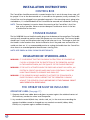
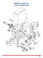
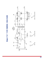
Models "ES" and "ESS" STUNNER Parts and Service Manual USDA APPROVED CE INSTALLATION OPERATION MAINTENANCE PARTS LIST & DIAGRAMS STUNNING PROCEDURES Model "ESS" Heavy Duty Electric Model "ES" Electric 5570 Creek Road • Cincinnati, OH 45242, USA TOLL FREE 1-800-553-2378 Phone: 513-791-9180 • FAX: 513-791-0925 E-Mail: [email protected] WEBSITE: www.bestanddonovan.com I N D E X Operator Safety................................................................. 2, 3, 4 Installation Instructions . ...........................................................3 Operation...................................................................................4 Adjustments & Maintenance Instructions............................ 4, 5 Stunning Voltage Chart............................................................. 5 Models "ES" and "ESS" Control Boxes, Wiring Diagrams, Parts & Numbers . ...... 6 - 14 Handle Complete - Parts & Numbers ................................... 15 Stunning Procedures for Pigs over 200 lbs. and illustrated instructions for Insulation, Start-up & Storage................. 16 - 25 Equipment Cleaning Record sheet ........................................ 26 Equipment Maintenance Record sheet . ................................ 27 Warranty Information..............................................................28 WARNING THE STUNNING PRODS ARE HIGH VOLTAGE. NEVER ALLOW HUMAN CONTACT. PERSONAL INJURY, PARALYSIS OR DEATH MAY RESULT. WARNING Always exercise care when operating or per forming maintenance, repairs, and making adjustments. Always disconnect the electric supply before attempting to work on the Model “ESS" or Model “ES” Stunners. Never allow any part of your person to be in the path of the Prod when in service (operation). Always grip the Prod hand-piece firmly. 2 INSTALLATION INSTRUCTIONS CONTROL BOX The Control Box should be mounted in a remote location that is out of the area where water will be sprayed. It has to also be mounted so it is accessible to the operator (usually overhead). The Control Box must be plugged into a grounded receptacle. If the mounting area is going to be washed down, it is recommended that the Control Box be removed until needed for stunning. NOTE: The most important instruction about the mounting of the Control Box is that it be kept as dry as possible. Water or constant dampness could cause circuits in the box to malfunction or short out. STUNNER HANDLE The No. 9600100 Stunner Handle Assembly plugs into the bottom of the control box. The handle must be easily moved into position where the operator can stun the animal. The Stunner Handle should have a sturdy and safe place to be hung or laid when not in use. The hanger or shelf that the Handle is to be rested on must also be insulated so that if the prods were activated the unit would not short out. It is a recommended practice to unplug the handle from the Control Box when there is an extended period of time between stunning shifts. NOTE: KEEP PRODS & SPURS CLEAN FOR BEST RESULTS. INSULATION OF STUNNING AREA WARNING: IT IS IMPORTANT THAT THE FOLLOWING INSTRUCTIONS BE FOLLOWED AS CLOSELY AS POSSiBLE FOR THE PROTECTION OF THE OPERATOR, ANYONE IN THE IMMEDIATE AREA, AND THE QUALITY OF THE FINISHED PRODUCT. WARNING: IF THE UNIT IS ACTIVATED WHEN THE PRODS ARE AGAINST ANY METAL, AN ELECTRICAL CIRCUIT WILL BE MADE WHICH WILL EVENTUALLY CAUSE THE MAIN TRANSFORMER TO OVERHEAT AND BURN OUT. WARNING: IF THE OPERATOR SHOULD HAPPEN TO ACTIVATE THE STUNNER WITH A PROD TOUCHING A METAL SUPPORT THAT THE OPERATOR IS LEANING AGAINST, THE OPERATOR COULD BECOME PART OF THE STUNNING CIRCUIT AND EXPERIENCE A SEVERE SHOCK. THE OPERATOR MUST BE INSULATED OPERATOR’S AREA (See page 11) 1. Operator should wear rubber boots and gloves to protect against the accidental contact of the Prod to any conductive surface near the operator. 2. Any conductive material (black iron, stainless steel, etc.) in the structure surrounding the operator should be covered or changed to a non-conductive material (rubber, delrin, UHMW, etc.) to protect against accidental shocking. 3 THE OPERATOR MUST BE INSULATED (cont’d) HOG, CHUTE AND/OR RESTRAINER (See page 11) 1. Any part of the chute or restrainer that comes in contact with the hog at the time of stunning must be covered or constructed of non-conductive material so the electric charge from the stunner does not short across the hog to the chute wall. This includes bolts, nuts and any other kind of fasteners used in its construction. 2. If at all possible, the hogs should not be touching each other in any way. The charge from the Stunner could go from the stunned hog to the other and affect the immobility of the stunned animal. OPERATION 1. Before plugging in, make sure that the Handle Assembly Prods and Spurs are “CLEAN”. 2. The animals should be lightly sprayed with water, this provides for better electrical contact and reduces the voltage required for stunning. 3. MAKE SURE THAT THE MAIN SWITCH IS IN THE “OFF” POSITION. Plug the Control Box into the proper, grounded receptacle, (Check the Nameplate for the Correct Voltage). Plug the Stunner Handle Assembly into the bottom of the Control Box. Set the Selector switch to low. Then turn the Main switch to the “ON” position. 4. As the animal passes the operator, the operator should place the Prods firmly against the animal with the Prod Spurs on each side of the head directly behind the ears, see page 10. At this time of contact the operator presses the handle button and the timer will shut off after the set time. The animal will stiffen up and as this happens it will drop, STUNNED. NOTE: See Adjustable TIME-OUT Feature in next section for changing length of stunning times to accommodate various size animals. 5. Immediately after stunning, the animal should be shackled and bled, see page 17. Shackling should take place no later than TEN (10) seconds after stunning. Sticking should be done no later than FIFTEEN (15) seconds after stunning as the animal may regain consciousness. ADJUSTABLE TIME-OUT FEATURE This feature was designed so that the operator could pre-set the length of stunning time when the Handle push button is depressed. This stunning time can be adjusted from 1 to 9 seconds by turning the Potentiometer clockwise for longer stunning time and counterclockwise for less stunning time. The numbers on the faceplate are for reference ONLY; THEY DO NOT REFLECT ACTUAL TIME SETTING. It will be necessary for the operator to experiment with the setting to accommodate the size and weight of the animals being stunned. This feature also provides some protection to the power transformer from burnout due to extended activation. Should stunning times become excessive, it is recommended that the Handle Assembly be disconnected from the unit and the Prod ends cleaned to permit good electrical contact with the animal. NOTE:Handle Assembly should also be inspected for shorts or bare wires that could cause injury to the operator or cause damage to the Control Box. 4 MAINTENANCE “Maintenance Inspection and Repair Programs” should be set up for the care of all Stunners. Safe operation depends on care being given to the unit as a whole. 1. To keep the Stunner working at its peak efficiency, it is to be kept as dry as possible 2. There is a 15 Amp fuse located next to the Handle Plug on the bottom of the Control Box. Check. this fuse if the Control Box will not work. 3. The Handle Prods and Spurs must be kept clean because of the build-up that occurs from the hair of the hog. This film thickens on the Prods, steel wool, wire brushes or sand paper will clean the metal for more effective stunning. WARNING:DISCONNECT THE CONTROL BOX FROM THE POWER SOURCE AND UN-PLUG THE HANDLE BEFORE CLEANING THE PRODS. 4. Check for fraying of the power cord to the Handle. This may occur from the way the handle is positioned to stun the hogs. 5. The voltage at the Prods can be checked by “CAREFULLY” using a voltmeter attached to the Prods. 6. Individual components and wires can be checked using an ohmmeter, EVEN WITHOUT HAVING THE UNIT PLUGGED-IN. 7. A 110 Volt wiring diagram is provided in this catalog. NOTE: A transformer has been used to drop the relay and control circuit to six (6) volts for operator protection. Models "ES" and "ESS" STUNNING VOLTAGE CHART Every installation is different but the principle is the same. Use the least amount of voltage when stunning to avoid blood spotting and broken backs, but use enough to keep the animal immobilized until it is shackling and bled. NOTE: Hog Weight (lbs) Voltage* 250 to 350 400* 350 to 500 420* 500 to 650 460* It is recommended that a lower voltage stun for a longer period of time is more efficient than a high voltage stun at a short period of time. *Output voltage is related to clean input voltage so this chart is variable. 5 9600042 - Model "ES" 110V CONTROL BOX 6 9600042 - Model "ES" 110V CONTROL BOX REF. No. PART NUMBER 9609500 9605400 9601700 9609869 9609872 9609824 9601000 9602300 9609866 9600048 9601800 9605900 9609100 9600840 9607400 9901704 9901645 9600033 9600032 9600031 9605500 9609802 9609810 9609828 9609200 9609822 9609820 9900088 9609816 9609818 9609826 9609875 9609878 9609881 9609814 1 2 3 4 5 6 7 8 9 10 11 12 13 14 15 16 17 18 19 20 21 22 23 24 25 26 27 28 29 30 31 32 33 34 35 DESCRIPTION WELDMENT - COVER FRONT PANEL TRANSFORMER SELECTOR SWITCH - 2 POSITION CONTACT BLOCK - N.O. “0” RING 4 - POLE RECEPTACLE CABLE CONNECTOR 3 POSITION SELECTOR SWITCH FUSE - 15 AMP MDA FUSE HOLDER COMPLETE RELAY PILOT LIGHT COMPLETE PAN HEAD SCREW LOCKNUT HEX HEAD NUT HEX HEAD NUT ON - OFF SWITCH HI - LOW SWITCH COMPLETE 3 - POSITION SWITCH COMPLETE LEGEND PLATE 120 VOLT PC BOARD 10 - PIN CONNECTOR ASSEMBLY LED SLEEVE NEON BULB POTENTIOMETER KNOB ROUND HEAD SCREW 2 PC BOARD HOLD DOWN BRACKET PC BOARD CUSHION LED CONTACT BLOCK NC/NO CONTACT BLOCK NO/NO CONTACT BLOCK NC/NO 10 - PIN CONNECTOR BRACKET QTY 1 1 1 2 1 1 1 1 1 1 1 1 1 2 1 4 8 1 1 1 1 1 1 1 1 1 1 1 1 1 1 1 1 1 7 8 WHT F1 15A BLK 563 585 2 L1 1 ON 1 2 562 OFF/ON OFF 564 580 579 577 HI/LO SWITCH LOW 580 H2 H1 X1 H3 H4 H5 X2 X3 GRN 587B X4 588B HIGH RED 582 XMFR TA-2-32405 (250 VA) 586 588A 587A GRN 2 RED 2 3 POSITION SWITCH LO - 400 320 280 HI - 620 550 500 GRN 1 RED 1 590 Model "ES" 110V WIRING DIAGRAM 589 578 Z Y 588A H4 H3 H2 569 570 586 H1 589 LED X2 X3 588B X4 587B 566 TIMER X1 580 567 587A H5 TRANSFORMER TA-2-32405 (250VA Model "ES" 110V WIRING DIAGRAM NEON LAMP 586 562 579 580 2 4 3 1 1 3 4 2 565 573 WHT 564 BLK FUSE 15A 588B 1.576 2.575 3.573 4.571 (4).570 5.569 6.568 7.567 8.566 9.565 10.563 578 RED ON/OFF SWITCH 575 589 Z 571 568 RED 2 GREEN 2 HI/LO SWITCH 585 587A 3 POS. SWITCH 587B 578 Y X W 563 564 580 590 GRN 577 588A RED 1 579 GREEN 1 562 WHT BLK GRN GROUND 9 9600043 - Model "ES" 220V CONTROL BOX 10 9600043 - Model "ES" 220V CONTROL BOX REF. No. PART NUMBER 9609500 9605700 9604700 9609869 9609872 9609884 9602300 9607400 9601000 9609863 9600048 9601800 9606000 9609000 9900840 9901704 9901645 9605600 9900033 9600030 9609822 9609820 9609826 9609200 9609828 9609824 9609810 9609804 9609816 9609818 9900088 9609814 1 2 3 4 5 6 7 8 9 10 11 12 13 14 15 16 17 18 19 20 21 22 23 24 25 26 27 28 29 30 31 32 DESCRIPTION WELDMENT - COVER FRONT PANEL TRANSFORMER SELECTOR SWITCH - 2 POSITION CONTACT BLOCK - N.O. CONTACT BLOCK - KA1 CABLE CONNECTOR LOCKNUT -112” N.P.T./WASHER 4 - POLE RECEPTICAL SELECTOR SWITCH - 4 POSITION FUSE - 15 AMP MDA FUSE HOLDER COMPLETE RELAY PILOT LIGHT COMPLETE 10-32 x 3/8 PAN HEAD SCREW 10-32 HEX NUT 8-32 HEX NUT LEGEND PLATE ON - OFF SWITCH 4 - POSITION SWITCH COMPLETE POTENTIOMETER - 1 MEGAOHM KNOB L.E.D. NEON BULB L.E.D. SLEEVE “O” RING 10 - PIN CONNECTOR DURATION PC BOARD 1 - 11 SECOND PC BOARD HOLDDOWN BRACKET PC BOARD CUSHION 6-32 x 114 ROUND HEAD SCREW 10 - PIN CONNECTOR BRACKET QUANTITY 1 1 1 1 1 2 1 1 1 1 1 1 2 1 4 4 8 1 1 1 1 1 1 1 1 1 1 1 1 1 1 1 11 9600011 - Model "ESS" 110V CONTROL BOX 1 5 6 7 8 2 3 4 9 10 32 11 12 33 11 13 14 15 23 17 24 25 31 26 27 16 12 17 17 18 20 19 21 22 28 30 29 11 9600011 - Model "ESS 110V CONTROL BOX REF. No. QTY 1 2 3 4 5 5 6 7 8 9 10 11 12 13 14 15 16 17 18 19 20 21 22 23 24 25 26 27 28 29 30 31 1 1 1 1 1 1 1 1 1 1 1 1 1 1 1 2 2 8 1 1 1 1 1 8 1 1 1 2 1 1 4 1 DESCRIPTION Gauge AC Volts 0-600 Gauge AC Amperes 0-3 Front Control Panel Legend Plate 110V Led sleeve O-Ring Led Pilot Light Complete Neon Bulb Knob - 1/4” Shaft Potentiometer - 1 Megohm 2 Position Switch Contact Block N/O Contact Block 1 N/O & 1 N/C 3-Way Switch Contact Block 1 N/O & 1 N/C Relay 110V #8 Hex Nut Fuse Holder Complete Fuse 15 Amps MDA Slow Blow Cable Connector Locknut 4-Pole Receptacle #10 Hex Nut Transformer Duration PC Board (1-11 Sec.) 1- Pin Connector Assembly #6-32 x 1/4” Round Head Screw Circuit Board Hold Down Bracket Circuit Board Cushion #10-32 x 3/8” Pan Head Slotted Screw Top Control Weldment PART NUMBER 9602010 9602009 9602021 9602011 9609828 9609824 9609826 9609100 9609200 9609820 9609822 9609704 9609728 9609724 9609708 9609884 9605900 9901675 9601800 9600048 9602300 9607400 9601000 9901704 9602027 9609802 9609810 9900088 9609816 9609818 9900840 9602026 Reference 32 33 1 1 Hi-Lo Switch Complete On-Off Switch Complete 9609753 9609750 13 63 65 66 67 68 69 70 71 FUSE 64 64 ON/OFF 62 R1 - 66 - + LED 67 79 R2 77 RE + NEON 83 70 TIMER 85 N.C. 88A HI/LO N.O. 87A 76 73 82 80 - 88A 87A AMP H3 H4 H5 84 + 89 Z O O W 68 86 88 87 89 89 + VOLTAGE - 78 78 Y O O X 71 750 TRANSFORMER X1 X3 X4 H1 N.O. 78 86 VOLT N.O. 87 N.C. 68 N.O. 77 85 62 63 1 2 3 4 75 73 Model "ESS" 110 Volt - WIRING DIAGRAM 75 R1 R2 LED LED + PL U G TIM E R TIM E R PLU G R2 R2 GR OU ND 14 4 3 2 1 79 POWER 65 80 20 #9600100 HANDLE COMPLETE REF. NO. PART NO. 9600800 9601900 9609400 9607600 9608200 9600700 9602800 9607900 9608000 9900161 9607800 9608400 9608300 9608500 9603900 9608100 9607850 9608600 9600900 9603910 9603800 9600017 1 2 3 4 5 6 7 8 9 10 11 12 13 14 15 16 17 18 19 20 21 22 DESCRIPTION COIL TYPE CORD CORD CONNECTOR PVC HANDLE ONLY MOUNTING PLATE GASKET PUSH BUTTON SWITCH COVER SWITCH SCREWS TERMINALS SCREWS SCREWS PROD HOLDER SCREWS PROD - LEFT Spur, Collar Assy & Screw COLLAR - ONLY SCREWS PROD - RIGHT 4 POLE PLUG SPUR (only) SHEEP PROD PROD - EXTENSIONS QTY 1 1 1 1 1 1 1 4 2 2 2 1 4 1 2 2 2 1 1 2 2 2 15 Recommended Stunning Procedures. For pigs larger than 200 pounds. For animals over 200 lbs: use Wand Extension tips and Stainless Steel Spurs to assure correct Stun Wand contact. Note: Stainless Steel Star Wheels (spurs) conduct better than carbon steel. Wand Extensions and Star Wheels (spurs) are available from B&D, Order: Wand Extension - Part #9600017 Stainless Steel Star Wheel - Part #9603900 The Wand Extension tips and extra Star Wheels (spurs) assure correct Stun Wand contact with brain. Locate wand as close to the ear as possible, in the thin crevice. Note that this wand has two sets of star wheels for small and large pigs. 16 The longer, wider wand tips help to facilitate secure contact on the head of larger pigs It is best to restrain the pig during stunning to prevent Stun Wand slips or pig falling. Insulate swing gate and wall to restrain the animal during stun. Restraining the pig during stun can assure an effective stun. Wooden gate is non-conductive. Before stunning, insulate the stun box to prevent grounding during stun. Truck rubber mats on floor and wall. Coated metal gate. Plastic lining in stun box area to insulate electrical current. 17 At startup: Prior to use, inspect and test the wand. Turn on the stunner. Press the stunner button to test wand. Observe wand for electrical shorts. Service if necessary. Select the correct voltage for size and weight of pig, see Voltage Chart on Page 6. Prior to stunning, be sure the head and heart areas of each pig is wet. Automatic shower in holding pen. 18 It is best to wet hogs prior to entry in the stun box area. Stunning: Stun the head for a minimum of 3 seconds. Place wand in the thin crevice behind the ear, as close to the ear as possible. Target the pocket of the ear to assure that the brain is stunned. Check the eye to assure that the pig is insensible before stunning the heart Inspect the eye of the pig, but do not touch it. There should be no natural blinking. If the pig is still sensible, re-stun the head before stunning the heart. 19 Stunning: Stun the heart for a minimum of 3 seconds. Stun the heart of the pig. Target placement of the wand contacts behind the arm pit and on the chest. Check the eye to assure that the pig is insensible before shackling (hoisting) and before bleeding. Inspect the eye of the pig, there should be no natural blinking. You can wave a hand in front of the eye and look for “tracking or movement”. 20 Do not touch the eye, as corneal reflex may still be present on an electrically stunned pig. In electrically stunned pigs, gasping is a sign of a dying brain. Agonal gasping occurs when the pig’s mouth opens and closes and the head jerks slightly (like a fish out of water). Rapid seizure blinking and nystagmus (eye vibration) can also occur in electrically stunned animals. Signs of returning to sensibility, (beginning to regain consciousness). • The eyes are focused and pig is blinking naturally • Signs of rhythmic breathing, sides are moving up and down. 21 Signs of Sensibility (fully conscious). Vocalization. Order of Events during return to sensibility in CO2 stunned pigs. Average These events are very variable. Time Corneal reflex (touch eye) 42 sec Rhythmic breathing 68 sec Excitation 76 sec Nystagmus (vibrating eyes) 86 sec Spontaneous natural blinking 93 sec Conscious movement (Righting reflex) 171 sec Attempt to stand up 387 sec Righting Reflex: The pig tries to lift it’s head and right itself. Re-stun (if necessary) before bleeding, Captive Bolt. Danish Meat Research Institute, Holst (2001) Correct location for captive bolt or free bullet stunning of a pig. 22 Correct bolt location and angle to show brain destruction. Re-stun if necessary before shackling and bleeding (electrical). If the pig is still sensible, re-stun the head first. Then re-stun the heart. Bleeding should be rapid with a large volume. For head/heart stun, target to bleed the pig within 30 seconds, with a maximum of 60 seconds between stun and bleed. Good bleed If a large volume of blood does not appear, re-stick the pig. Weak bleed 23 Smoking indicates poor Stun Wand conductivity, immediately clean the stun wand contacts. Smoking indicates poor conductivity. WARNING:Always unplug the stun wand prior to cleaning. Routinely clean the stun wand, approximately every 5 pigs. Use a steel brush or a green pad to clean the wand. 24 Do not store the stunner on the plant floor. Model ESS Model ES Heavy Duty Electric Electric Storage After production, clean the Stun Wand and store the Stunner and Wand in a clean, dry location away from the plant floor,never on the plant floor. Follow all recommendations for equipment safety and maintenance. Use only B&D replacement parts. Models "ES" and "ESS" STUNNER Parts and Service Manual USDA APPROVED CE INSTALLATION OPERATION MAINTENANCE PARTS LIST & DIAGRAMS STUNNING PROCEDURES Model "ESS" Heavy Duty Electric Model "ES" Electric 5570 Creek Road • Cincinnati, OH 45242, USA TOLL FREE 1-800-553-2378 Phone: 513-791-9180 • FAX: 513-791-0925 E-Mail: [email protected] WEBSITE: www.bestanddonovan.com Thoroughly read Stunner P&S Manual, follow all recommendations and make available to operators. Document equipment cleaning and maintenance, see B&D Record Sheets pages 26 & 27. Photographs Pages 10 - 19, furnished by Erika Voogd, Voogd Consulting, Inc. 25 “1” Manu fac tu r “1” Manu s No. fac rld tu r Wo ts uc Th e 26 s No. rld Wo Th e DATE DESCRIPTION SERVICE BY ts uc TYPEOFMACHINE: MANUFACTURER:BEST & DONOVAN S in c e 1 9 2 4 utomate and A dP ro d utomate and A dP ro d S in c e 1 9 2 4 EQUIPMENT CLEANING RECORD s aw table Power Me Por at of S er s aw table Power Me Por at of S er SERIAL# MODEL# TIME SHIFT COMMENTS ••• RUN COPIES OF THIS SHEET FOR FURTHER RECORDS ••• COMPLETE ts uc “1” Manu fac tu r “1” Manu fac tu r s No. rld Wo s No. rld Wo Th e Th e DATE REPAIR DESCRIPTION ts uc TYPEOFMACHINE: MANUFACTURER:BEST & DONOVAN S in c e 1 9 2 4 utomate and A dP ro d utomate and A dP ro d S in c e 1 9 2 4 EQUIPMENT MAINTENANCE RECORD s aw table Power Me Por at of S er s aw table Power Me Por at of S er SERIAL# MODEL# DATE DATEPARTS PARTS SERVICE ORDERED REC’D INSTALLED BY COMMENTS ••• RUN COPIES OF THIS SHEET FOR FURTHER RECORDS ••• COMPLETE 27 Shown here is Best & Donovan’s main factory in Cincinnati, Ohio, USA. B&D also has a second manufacturing plant in Oak ridge ,Tennessee. WARRANTY Best & Donovan warrants this machine against defective parts and workmanship for 30 days from the date of factory shipment. In the fulfillment of its warranty, the sole obligation of Seller shall be to repair or replace, at its option F.O.B. its factory, shipping charges prepaid, and which after inspection by Seller are found to be defective. Buyer shall notify Seller of defect in writing, promptly upon discovery, within the warranty period. This warranty does not cover defects caused by corrosion or normal deterioration. It does no extend to consequential damages, loss or delay associated with a warranty defect and it does not cover any costs of labor, travel or other expenses associated with the repair or replacement of defective parts. Seller assumes no liability for product loss or other claims whatsoever arising out of the use or application of the machine in Meat Slaughtering/Processing operations, whether the machine is used alone or in conjoint use with other Meat Slaughtering/Processing machines or Process. This warranty is voided if repairs, replacements or alterations are made by others without prior authorization by Seller. Notwithstanding the foregoing, Seller warranty obligations with respect to any items not manufactured by Seller shall not exceed the obligations undertaken by the manufacturer thereof under express warranty to the Seller. This express warranty is in lieu of all other warranties of fitness of the machine for any particular purpose. NOTICE ON WARRANTY WORK Any warranty work that is to be considered by Best & Donovan on the Model "ESS" Stunner will be done by a service representative of Best & Donovan at the place of use or the entire Model “ESS” Stunner in question must be sent to Best & Donovan for evaluation and consideration for warranty. Use only Genuine Best & Donovan replacement parts for the repair of the “Model “ESS” Stunner. Any other parts used may void the warranty. Parts not manufactured by Best & Donovan and used for the repair of the Model “ESS” Stunner can cause power loss. A performance decrease and shorter life of the tool can be expected. Check to make sure the correct parts are being used. 5570 Creek Road • Cincinnati, OH 45242, USA TOLL FREE 1-800-553-2378 Phone: 513-791-9180 FAX: 513-791-0925 E-Mail: [email protected] WEBSITE: www.bestanddonovan.com Revised August 2014