1
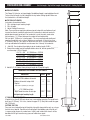
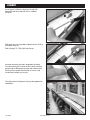
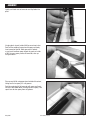
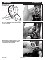
Carbon
Jib Reefing & Furling
Installation Manual
Unit 2/2.5
TABLE OF CONTENTS
Parts
3
Pictures and list of all parts
Specifications
4
Rod sizes
Clevis pin sizes
Luff tape sizes
Rigging, attachment to lower unit
Retrofits, fitting rod
Tools required
Supplies for gluing foils
Alignment splints
Headstay length
Preparation for Assembly
5-6
Foil cut length
Top foil cut length
If you have a short top foil
Cutting top foil
Assembly
7-11
Sliding foils onto rod
Attaching feeder
Joining foils using connectors
Preparing foil for gluing
Gluing foils using Hysol® adhesive
Gluing feeder
Aligning joined foils
Sliding halyard swivel onto foils
Capping foils with trim cap
Removing splint
Installing Navtec® eye
Installing carbon furling unit
Assembling turnbuckle
Foil height
Commissioning
12-16
Tying soft attachment lines
Halyard wraps
Prevent halyard wraps
Pendants
Halyard restrainer
Halyard tension
Warranty
Warranty of Harken Carbon parts is
one year from the time of purchase.
2
2/2.5 Carbon Furler
December 2001
PARTS
1
2
Prefeeder
Toggle
Cross pin*
Smalley Ring
Bottom (Feeder)
Connector
Clevis pin
Cotter pin
Top Bushing
Torque Tube Connector
*Cross pin includes (2) H2912A bushings.
(36) Connector bushings
Regular Connectors
3
4
Halyard
Swivel
Trim Cap
5
Feeder
1
Prefeeder . . . . . . . . . . . . . . . . . . . . . . . . . . . . . . . . . . . .
Toggle . . . . . . . . . . . . . . . . . . . . . . 5/8" (15.9mm) . . . .
Toggle . . . . . . . . . . . . . . . . . . . . . . 3/4" (19mm) . . . . . .
Cross Pin . . . . . . . . . . . . . . . . . . . 5/8" (15.9mm) . . . .
Cross Pin . . . . . . . . . . . . . . . . . . . 3/4" (19mm) . . . . . .
Cotter Pin . . . . . . . . . . . . . . . . . . . . . . . . . . . . . . . . . . .
Smalley Rings . . . . . . . . . . . . . . . 5/8" (15.9mm) . . . .
Smalley Rings . . . . . . . . . . . . . . . 3/4" (19mm) . . . . . .
Clevis Pin . . . . . . . . . . . . . . . . . . . 5/8" (15.9mm) . . . .
Clevis Pin . . . . . . . . . . . . . . . . . . . 3/4" (19mm) . . . . . .
947
H-29364C
H-27385C
H-29388A
H-27407A
HFG344
HCP1352
HCP1062
H-29385A
H-29386A
Bottom (Feeder) Connector . . . . . . . . . . . . . . . . . . . . .
Regular Connectors . . . . . . . . . . . . . . . . . . . . . . . . . . .
Top Bushing . . . . . . . . . . . . . . . . . . . . . . . . . . . . . . . . .
Torque Tube Bushing . . . . . . . . . . . . . . . . . . . . . . . . . .
H-27448BF
1096F
H-27508BF
H-27902BF
2
3
Lower Unit
Assembly
Connector Bushings (36) . . . . . . . . . . . . . . . . . . . . . . . H-27495A
Trim Cap . . . . . . . . . . . . . . . . . . . . . . . . . . . . . . . . . . . . H-27904B
Feeder . . . . . . . . . . . . . . . . . . . . . . . . . . . . . . . . . . . . . . H-29238B
4
Halyard Swivel . . . . . . . . . . . . . . . . . . . . . . . . . . . . . . . H-29662C
5
Lower Unit Assembly . . . . . . . . . . . . . . . . . . . . . . . . . . H-27374EF
Lacing Lines (3) 1/4" (6mm) Spectra® . . . . . . . . . . . . . HFG6907
May 2002
2/2.5 Carbon Furler
3
SPECIFICATIONS
■ Rod Sizes
-12, -17, -22 (7.14mm, 8.38mm, 9.53mm)
■ Tools Required
Sharp Hacksaw, Sandpaper, Small Triangular File, Heat Gun,
Razor Knives, Sandpaper.
■ Clevis Pin Sizes
5/8", 3/4" (15.9 mm, 19.1 mm)
■ Luff Tape Size
#6, 6/32", (5mm)
■ Rigging, Attachment to Lower Unit
If no turnbuckle is required, attach the rod marine eye directly
to the integral toggle on the 2.5.
If a turnbuckle is required, it must terminate in a marine eye
that will fit directly to the integral toggle. Use a Navtec C560
turnbuckle or similar for rod with either a 5/8" (15.9mm) pin or 3/4" (19mm) pin diameter.
■ Retrofits, Fitting Rod
If you plan to reuse the existing rod and turnbuckle:
Lower End—If you are using a standard Navtec turnbuckle
with integral toggle, the lower body must be replaced with a
standard Navtec marine eye body. Check to make sure that
this eye will mate with the Harken integral toggle. Two cross
pin sizes are available. They are the same size as the clevis
pin. See above.
Upper End—You must take apart the marine eye so that you
are left with a threaded nosepiece. Check to see if this is possible. If necessary, contact Navtec or Riggarna for correct procedure. You will slip carbon foils over this threaded nosepiece.
If you cannot remove this fitting you will need to cut the rod.
4
■ Supplies Required for Gluing Foils
Rigging tape, blue masking tape, 9430 Hysol Epoxy (supplied), Scissors, mixing cup, mixing stick, glue brushes,
acetone, paper towels cut into quarters, plastic to cover splint area, clear packaging tape, wood alignment stick and placemat-sized table covering.
Alignment Splints - Use 90° angle extrusion to make splints.
Sides to be about 3/4" (19mm). Cut extrusion into 8" (203mm)
lengths and remove burrs from cutting.
■ Headstay Length
Note: When cutting rod to length or making up new rod, make
sure that you can take apart the rod terminal (usually the top
eye) so that you are left with a threaded nosepiece.
Make up the rod headstay or adjust the turnbuckle so the
Harken toggle fits below the rod terminal eye. The pin-to-pin
distance of the Harken toggle is 31/4" (83mm).
Note: The 2.5 Carbon furler has an integral toggle. No additional toggle is required below the furler.
2/2.5 Carbon Furler
May 2002
PREPARATION FOR ASSEMBLY
Foil Cut Length • Top Foil Cut Length • Short Top Foil? • Cutting Top Foil
■ FOIL CUT LENGTH
The Carbon 2.5 furler has an integral toggle. No additional toggle is required below the unit.
To check the foil length, lay foils alongside the stay before cutting top foil. Make sure
that turnbuckle is set to desired length.
■ TOP FOIL CUT LENGTH
Instructions for worksheet below:
1 Fill in total pin-to-pin headstay length.
2 Fill in A length.
3 Adjust B length if necessary.
Note: There must be enough space between top of carbon foils and bottom of rod terminal to allow for turnbuckle adjustment. As turnbuckle is adjusted, terminal is
pulled down towards top of rod. If no turnbuckle is used, there only needs to be minimal space—1/2" (12mm)–between the carbon foil and rod terminal.
We have put 4" (100mm) as a starting point. This may need to be adjusted based upon how turnbuckle was set when headstay was measured. If there is less than 4" (100mm) “take-up”, less space can be left and vice versa. The space between foil
trim cap and bottom of turnbuckle must be more than “take-up” on turnbuckle.
4 Add A, B, E and subtract from total pin-to-pin headstay length. SUM = _________
5 Choose the number from foil multiplier below closest to, but not greater than, sum from step 4. Fill in D length.
6 X 72" = 432 6 X 1828.8mm = 10972.8
7 x 72" = 504 7 x 1828.8mm = 12801.6
8 x 72" = 576 8 x 1828.8mm = 14630.4
9 x 72" = 648 9 x 1828.8mm = 16459.2
10 x 72" = 720 10 x 1828.8mm = 18288.0
11 x 72" = 792 11 x 1828.8mm = 20116.8
A
C
D
5 Add A, B, D, E. Subtract from pin-to-pin length for C (top foil length).
WORKSHEET: DETERMINE TOP FOIL LENGTH
Dimensions
A Center of PIN to bottom of terminal
B Bottom of terminal to top of foil
Inches
mm
______________
4
102
C Top foil
Foils below 8" (203mm) see next page
______________
D _____ x 72" (1828.8mm) foils
______________
E Top of feeder to center of clevis pin
Total pin-to-pin headstay length
523/4
E
1340
______________
IF YOU HAVE SHORT TOP FOIL
If top foil is less than 8" (203mm) do not use a recessed top connector. The top foil must
be at least 4" (101mm). If it is less, shorten the upper 72" (1.83m) foil to make the upper
foil 4" (101mm).
CUTTING TOP FOIL
Once you have checked the top foil length by laying foils alongside the rod, use a sharp
hacksaw to cut top foil. Tape foil and cut along tape. Sand bottom end of the foil so it is square and to remove any carbon burrs. Lightly sand inside of foil where it will be
bonded with 220 grit to remove any grease or mold release agent.
June 2002
2/2.5 Carbon Furler
5
PREPARATION FOR ASSEMBLY
Tape outside ends of all foils using blue masking tape. To
make sure tape edge lines up with end of foil, extend the tape over foil end. Use a sharp razor knife to trim tape even
with foil.
Coat rod with mold release agent or wax to keep epoxy from adhering.
Heat rod terminal and remove threaded screw and threaded
nosepiece. If rod terminal has been upset (peened), follow
Navtec or Riggarna procedures for removing peening.
Tape threads of nosepiece and tape nosepiece so it will not
slip down foil when pushing it back out.
6
2/2.5 Carbon Furler
December 2001
ASSEMBLY
Assuming that installation is done from the top, slide bottom foil onto rod so end with holes is at bottom end of foil.
Slide feeder over so, so rounded sail groove corners will be at
the bottom end of foil.
Slide full-length 72" (1.83m) foils onto the rod.
Assemble connectors onto rod in preparation for glueing. Place one bushing half in socket on either side of connector,
grooved side up. Bring connector up on rod and place other
bushing half on rod and rotate bushing so seam is at top and bushing assembly stays in place.
Place foil on bench with grooves facing up and supported on
wood blocks.
June 2002
2/2.5 Carbon Furler
7
assembly
Cool Weather
Temperature should be higher than 60°F (15°C).
If you glue at a lower temperature:
50°F (10°C) minimum
gently warm joints with a hair dryer to no more than:
100°F (38°C), a temperature at which you can still hold the foil comfortably in your hand.
If glued in temperature less than 60°F (15°C, allow glued
foils to cure undisturbed for 48-hours before moving.
Adhesive Alert
You must follow four-step mixing instructions shown below exactly or the foil
connector bond will fail.
Warm Weather
Surfaces must be dry.
Adhesive Working Times:
75°F (24°C) - 1 hour
85°F (29°C) - 45 minutes
Allow glued foils to cure undisturbed for 24-hours
Remove plastic clip from Hysol® adhesive pack.
1) Mix for five minutes in bag.
2) Pour entire contents into cup.
3) Squeegee remaining epoxy into cup.
4) Continue to thoroughly stir epoxy in cup.
Use glue brush to coat the inside of the foil for one or two
inches. Coat 1/2 of the outside of the connector with epoxy
and slowly insert the connector into the foil. Work the connector in and out as you insert it to adhere the epoxy without
dry spots on the inside of the foil. As excess epoxy comes off
the connector, clean it up using the acid brush. Use excess
to coat feeder area of connector. Clean up the end of the foil
using paper towel wetted with acetone taking care that no
epoxy is in the sail grooves.
8
2/2.5 Carbon Furler
May 2002
assembly
Lightly coat feeder area of connector and slip feeder into
place.
Use glue brush to coat inside of foil for one or two inches.
Coat half the outside of connector with epoxy and slowly
insert connector into foil. Work connector in and out as you insert to adhere epoxy without dry spots on inside of foil. As excess epoxy comes off connector, clean up using acid brush.
Clean up end of foil using paper towel wetted with acetone,
taking care that no epoxy is in sail grooves.
Coat the remaining half of connector with epoxy and insert
into foil as described above, cleaning up excess epoxy. Take
special care to clean epoxy from sail grooves.
May 2002
2/2.5 Carbon Furler
9
assembly
Lay plastic against foil and place splint against foil. Tightly
wrap clear packaging tape around splint near both ends.
Insert wood alignment stick between foil and feeder and
inspect to make sure that foil/feeder are aligned.
Coat bottom foil reinforcement (torque tube connector) with
epoxy and insert into foil as directed above.
Insert plastic bushings in top connector as directed above.
Coat outside of connector with epoxy as directed above and
insert into top foil. Clean up excess epoxy.
Slide halyard swivel onto foils. Make sure swivel side is
towards top of stay!
Slide trim cap over threaded nosepiece. Heat cap in hot water to help it slide over nosepiece. Attach trim cap using
Superglue®.
Make sure foils are straight and grooves are facing up.
Inspect lower unit to make sure that feeder and bottom foil
are aligned correctly. Allow to cure undisturbed overnight.
After curing overnight, remove splint. Use a small triangular
file to clean excess epoxy while tape remains in place.
Remove tape and use a razor knife to carefully remove any
excess epoxy. Make sure halyard swivel passes all points.
Install top rod eye using red Loctite® on locking screw or with upset as per manufacturer's instructions.
Remove eight socket-head cap-screws located on underside
of lower unit and remove lower cap. Remove three set screws located at top of torque tube.
10
2/2.5 Carbon Furler
December 2001
assembly
Slide lower unit onto bottom foil.
Assemble turnbuckle. Attach turnbuckle eye to toggle using
cross pin with tapered ends. Secure Cross Pin using Circlip
(Smalley Rings) supplied. Note: Make sure the end of the toggle with the long slot is towards the bottom.
Long Slot
Bring the lower unit down so that Cross Pin seats in the housing. Install cap using Blue Threadlocker® on the eight screws.
■ FOIL HEIGHT
Check the clearance between the top of the foil and top terminal.
TIP: Check clearance when the unit is on the ground,
before raising the headstay into position.
WARNING: It is critical to have clearance between the top
foil and the top rigging fitting when the stay adjuster is in
the fully closed position. If the fittings touch, the unit will
jam or in the case of a Sta-Lok fitting, the terminal may
become unscrewed. This could cause catastrophic failure to the spar and a life threatening situation
It is the responsibility of the rigger to check clearance.
December 2001
2/2.5 Carbon Furler
11
COMMISSIONING
Tying Soft Attachment Lines
You must lace line around the furler/halyard swivel three times
when attaching the sail or halyard.
Harken recommends us of a Hunter's Bend. This knot can be highly tensioned without slipping and like a bowline can be untied afterwards. There are other bends and knots that
will also work.
Lace line three times around the torque tube/halyard swivel
to capture sail or halyard. After lacing line, tie ends on side
opposite sail.
1 Form a loop in line that comes from left tunnel. Below this,
form a second loop with line from the right tunnel.
2 Twist loop clockwise and arrange ends of line so they are
below standing loops as shown.
12
2/2.5 Carbon Furler
December 2001
COMMISSIONING
Tying Soft Attachment Lines
3 Take end that is now running down to right. Tuck it down under crossing lines and up through loop, towards you.
4 Pass other end up and over crossing lines and then down
into loop, away from you.
5 At this point knot will not look anything like the finished
bend. Set knot by gently pulling on bitter ends and then
standing parts until it looks like Drawing 6.
December 2001
2/2.5 Carbon Furler
13
COMMISSIONING
Tying Soft Attachment Lines
6
7 Finished bend drawn up and set. If your bend does not
look like this untie and repeat the process.
9 If furler is installed under deck, lace tack pendant as pictured. Rigging a pendant directly from carbon tunnels
will damage unit.
8 It is important to keep tack/luff as close to torque tube and
as low as possible. A tack line that is too long will angle up
too far and damage the carbon tunnels. When sail is bent on,
check to make sure tack line is not pulling up against the carbon tunnels.
14
2/2.5 Carbon Furler
December 2001
COMMISSIONING
Halyard Wraps • Prevent Halyard Wraps
■ HALYARD WRAPS
The most serious problem with furling systems occurs when
the jib halyard wraps around the headstay foil. Halyard wraps
will prevent furling or unfurling and may cause serious damage to the unit and the halyard. In severe cases, halyard wraps
may cause loss of the headstay.
To prevent wraps, the halyard must exert a slight pull to the rear. This allows the foils to turn while the halyard remains stationary.
■ PREVENT HALYARD WRAPS
WARNING: The sail must be fitted to foils before operation.
1 Halyard swivel should be within top 4" (100mm) of foil.
2 Halyard must pull slightly to rear (8 - 10°).
3 Halyard must be snug, but not too tight.
If a halyard wraps, do not force unit to turn. Attempt to open
sail by alternately furling and unfurling sail slightly.
If the sail can be unfurled, lower sail by releasing jib halyard.
Severe halyard wraps can only be cleared by going aloft and
freeing halyard.
If the sail will not furl or unfurl, it may be possible to remove
jib sheets and manually wrap/unwrap the sail around/from the headstay.
Important: Testing at the dock does not indicate halyard angle
is correct. In wave action, halyard may wrap if lead angle is
not correct. The diverging 8-10° angle mentioned above is
critical.
December 2001
2/2.5 Carbon Furler
8 - 10°
15
COMMISSIONING
Pendants • Halyard Restrainer
■ PENDANTS
If your sail is not long enough to position halyard swivel
properly, you must add a pendant to sail. Pendants should
be plastic-coated wire permanently attached to the head of
sail so height will be correct. Adjustable length pendants
are not acceptable as they might not be adjusted correctly
during a sail change.
■ INSTALL A PENDANT
1 Raise sail, but do not attach tack shackle.
2 Position halyard swivel correctly near top of headstay
and secure halyard.
3 Secure a piece of rope to sail tack. Lead line through
tack shackle on furling drum and tension sail.
4 Measure distance from tack shackle to sail tack and have a pendant of this length permanently attached to
head of sail.
5 Repeat this procedure for every jib.
TIP: Pendants are used at head of sail. Short pendants
may be added at tack to improve visibility under genoa, but
remember that visibility is already improved by shackling
to tack swivel. Tack pendants increase heeling moment
by raising sailplan. You may install pendants at both
head and tack of sail.
■ HALYARD RESTRAINER
To prevent wraps, the jib halyard must pull slightly to the rear. On some boats the halyard sheaves are located too close to the headstay and a halyard restrainer must be used.
Use halyard restrainers only when required by the masthead
geometry. Restrainers tend to limit sail luff length and may
cause problems if not properly installed.
Mount the restrainer as high as possible on the face of the mast. Position the restrainer so the foils will not hit it when under load.
The restrainer should deflect the halyard 8 - 10°. If the angle is more than 10°, you may experience difficulty in
tensioning the sail luff, friction in furling and possible damage
to the foils. To decrease deflection angles, shorten the luff of
the sail.
8 - 10°
TIP: Boats used in charter service should consider using a
halyard restrainer, regardless of masthead geometry.
16
2/2.5 Carbon Furler
December 2001
COMMISSIONING
Halyard Tension
■ HALYARD TENSION
The jib halyard should be firm, but not too tight.
TIP: The luff foil system supports the sail along its entire
length so halyard tension is required only to shape sails,
not to support them. Use only enough halyard tension to
remove some wrinkles along the luff. Do not tension the
halyard enough to cause vertical wrinkles in the luff. Use
halyard tension to adjust draft position of the sail to suit
sailing conditions. Your halyard should be firm but not
tight. If in doubt, release halyard tension. To protect
the sail, ease the halyard when the boat is not in use.
December 2001
2/2.5 Carbon Furler
17
Corporate Headquarters
1251 East Wisconsin Avenue, Pewaukee, Wisconsin 53072 USA
Telephone: (262) 691-3320 • Fax: (262) 691-3008 • Cable: Harken Pewaukee
Web: www.harken.com • Online Catalog: www.harkenstore.com
Email: [email protected]
Harken France
ZA. Port des Minimes, BP 3064, 17032 - La Rochelle Cedex 1, France
Telephone: (33) 05.46.44.51.20 • Fax: (33) 05.46.44.25.70
Web: www.harken.fr
Email: [email protected]
Harken Italy S.P.A.
Via Marco Biagi, 14, 22070 Limido Comasco, (CO), Italy
Telephone: (39) 031.3523511 • Fax: (39) 031.3520031
Web: www.harken.it
Email: [email protected]
Harken UK Ltd.
Bearing House, Ampress Lane
Lymington, Hampshire S041 8LW, England
Telephone: (44) 01590-689122 • Fax: (44) 01590-610274
Web: www.harken.co.uk
Email: [email protected]
Harken Poland
ul. Lisa Kuli 4 Lok.1, 01-512 Warszawa, Polska
Telephone: +48 607 979 747
Web: www.harken.com
Email: [email protected]
Harken Sweden
Mjölkekilsgatan 6, Box 64
S-440 30 Marstrand, Sweden
Telephone: (46) 303-618 75 • Fax: (46) 303-618 76
Web: www.harken.se
Email: [email protected]
Harken Adriatik d.o.o.
Obala 107
6320 Portoroz, Slovenia
Telephone/Fax: 5-6774122
Web: www.harken.si
Email: [email protected]
Harken Australia, Pty, Ltd.
1B Green Street
Brookvale, N.S.W. 2100, Australia
Telephone: (61) 2-8978-8666 • Fax: (61) 2-8978-8667
Web: www.harken.com.au
Email: info.harken.com.au
Harken New Zealand, Ltd.
30-36 Fanshawe Street
Auckland 1001, New Zealand
Telephone: (64) 9-303-3744 • Fax: (64) 9-307-7987
Web: www.harken.co.nz
Email: [email protected]
Please visit: http://www.harken.com/dealers/dealers.php
for an up-to-date list of Harken dealers and distributors
4362/9-08