1
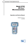
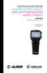
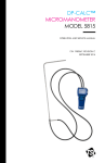
Ventilation Testing/Balancing Model 8340 Intrinsically Safe VELOCICHECK® Air Velocity Meter Operation and Service Manual 1980076, Revision E October 2002 Model 8340 Intrinsically Safe VELOCICHECK® Air Velocity Meter Operation and Service Manual 1980076, Revision E October 2002 U.S. Sales and Customer Service: (800) 874-2811 (651) 490-2811 Fax: (651) 490-3824 INTERNATIONAL Sales and Customer Service: (001 651) 490-2811 Fax: (001 651) 490-3824 SHIP/MAIL TO: E-mail address: TSI Incorporated [email protected] 500 Cardigan Road Website: Shoreview, MN 55126 USA www.tsi.com Copyright TSI Incorporated / August 2000–2002 / All rights reserved. Address TSI Incorporated / 500 Cardigan Road / Shoreview, MN 55126 / USA Fax No. (651) 490-3824 LIMITATION OF WARRANTY AND LIABILITY. Seller warrants the goods sold hereunder, under normal use and service as described in the operator's manual, shall be free from defects in workmanship and material for twenty-four (24) months, or the length of time specified in the operator's manual, from the date of shipment to the customer. This warranty period is inclusive of any statutory warranty. This limited warranty is subject to the following exclusions: a. Hot-wire or hot-film sensors used with research anemometers, and certain other components when indicated in specifications, are warranted for 90 days from the date of shipment. b. Parts repaired or replaced as a result of repair services are warranted to be free from defects in workmanship and material, under normal use, for 90 days from the date of shipment. c. Seller does not provide any warranty on finished goods manufactured by others or on any fuses, batteries or other consumable materials. Only the original manufacturer's warranty applies. d. Unless specifically authorized in a separate writing by Seller, Seller makes no warranty with respect to, and shall have no liability in connection with, goods which are incorporated into other products or equipment, or which are modified by any person other than Seller. The foregoing is IN LIEU OF all other warranties and is subject to the LIMITATIONS stated herein. NO OTHER EXPRESS OR IMPLIED WARRANTY OF FITNESS FOR PARTICULAR PURPOSE OR MERCHANTABILITY IS MADE. TO THE EXTENT PERMITTED BY LAW, THE EXCLUSIVE REMEDY OF THE USER OR BUYER, AND THE LIMIT OF SELLER'S LIABILITY FOR ANY AND ALL LOSSES, INJURIES, OR DAMAGES CONCERNING THE GOODS (INCLUDING CLAIMS BASED ON CONTRACT, NEGLIGENCE, TORT, STRICT LIABILITY OR OTHERWISE) SHALL BE THE RETURN OF GOODS TO SELLER AND THE REFUND OF THE PURCHASE PRICE, OR, AT THE OPTION OF SELLER, THE REPAIR OR REPLACEMENT OF THE GOODS. IN NO EVENT SHALL SELLER BE LIABLE FOR ANY SPECIAL, CONSEQUENTIAL OR INCIDENTAL DAMAGES. SELLER SHALL NOT BE RESPONSIBLE FOR INSTALLATION, DISMANTLING OR REINSTALLATION COSTS OR CHARGES. No Action, regardless of form, may be brought against Seller more than 12 months after a cause of action has accrued. The goods returned under warranty to Seller's factory shall be at Buyer's risk of loss, and will be returned, if at all, at Seller's risk of loss. Buyer and all users are deemed to have accepted this LIMITATION OF WARRANTY AND LIABILITY, which contains the complete and exclusive limited warranty of Seller. This LIMITATION OF WARRANTY AND LIABILITY may not be amended, modified or its terms waived, except by writing signed by an Officer of Seller. Service Policy Knowing that inoperative or defective instruments are as detrimental to TSI as they are to our customers, our service policy is designed to give prompt attention to any problems. If any malfunction is discovered, please contact your nearest sales office or representative, or call TSI's Customer Service department at (800) 874-2811 (USA) and (1) 651-4902811 (International). Contents Chapters 1 Setup .......................................................1 Unpacking................................................1 Installing the Batteries .............................1 2 VELOCICHECK Operation .....................3 Extending The Probe ...............................3 Measuring Velocity .................................4 Switching On The Power.........................4 Selecting Battery Life / Velocity Display 5 Selecting The Sensor Response ...............5 Batteries ...................................................6 3 Maintenance ...........................................9 Probe Tip .................................................9 Cases......................................................10 Storage ...................................................10 Recalibration..........................................10 Probe Replacement ................................11 4 Troubleshooting ...................................13 Appendixes A Standard Velocity Vs. Actual Velocity .................................................17 B Specifications........................................21 Chapter 1 Setup This chapter guides you through unpacking and installing batteries in your VELOCICHECK. See chapter two for a detailed description of the VELOCICHECK operating functions. Unpacking Carefully unpack the instrument and accessories from the shipping container. Check the individual parts against the list of components in Table 1; if any are missing or damaged, notify TSI immediately. Table 1: List of Components Qty Item Part No. 1 1 4 1 8340 1319042 1208013 1980076 VELOCICHECK Carrying Case AA Alkaline batteries Operation and Service Manual Installing the Batteries Install batteries by loosening the screw in the battery access cover located on the back of the instrument. Insert four AA-size alkaline 1 batteries in the battery tubes according to the polarity indicated on the instrument case under the battery access cover. Replace the battery access cover and tighten the screw. If the batteries are installed incorrectly, damage to the VELOCICHECK will not occur, but the instrument will not function. WARNING: The Model 8340 VELOCICHECK is only listed for intrinsic safety when operating with four size AA alkaline batteries. Batteries of other types (NiCd, carbon-zinc, etc.) are not acceptable for use in a hazardous environment. 2 Chapter 1 Chapter 2 VELOCICHECK® Operation This chapter thoroughly explains how to operate the VELOCICHECK. Extending The Probe The Model 8340 VELOCICHECK contains a retractable velocity probe which is shipped in its retracted position. To expose the probe to the flow for air velocity measurements, grasp the black tip of the probe which is visible in the center of the top of the instrument. Pull firmly straight up on the probe. Once fully extended to its three-inch length the probe can rotate 90° to facilitate measuring air from many directions. To retract the probe, align the sensor window so that you can view straight through the window from the front of the instrument. Once the window is aligned to the front, grasp the probe tip and push firmly straight into the instrument case. Always store the probe retracted when not in use in order to protect the sensor. 3 The Model 8340 is designed so that it can stand upright or on its sides in velocities up to several hundred feet per minute. This can be useful for making face velocity measurements in a cleanroom bench or a fume hood. As you handle the probe, take care not to bump it against duct walls or other objects. The probe has been made as rugged as possible, but can be damaged by careless handling. Measuring Velocity For highest accuracy, it is important with all VELOCICHECKs to properly align the probe to the flow. Orient the probe so that the air being measured flows straight through the sensor window in the direction indicated by the arrow at the tip of the probe. The arrow at the tip of the probe should point downstream. Switching On The Power Turn on the VELOCICHECK using the ON/OFF switch. The VELOCICHECK will display battery life for the first five seconds. This number represents the approximate battery life remaining, and will range from less than 0% for low batteries to something over 100% for a short time while the “surface charge” of new batteries burn off. 4 Chapter 2 After five seconds the VELOCICHECK will begin to display velocity in the selected units. Units available for display are standard feet per minute (S ft/min) and standard meters per second (S m/s), depending on what units were ordered when the unit was purchased. The units of measure cannot be changed in the field. Selecting Battery Life / Velocity Display The BATT/VEL switch on the instrument allows you to determine remaining battery life without turning the unit off. With the unit on, slide the switch to BATT to read the approximate percentage of battery life remaining. Slide the switch to the VEL position to read the current velocity. Selecting The Sensor Response The Model 8340 VELOCICHECK has a FAST/SLOW RESPONSE switch for setting the display averaging time. In the slow response mode, the VELOCICHECK displays the average velocity measured during the past 12 seconds. This is a running average, so the display is still update once per second. In the fast response mode, the meter displays the average velocity measured during the past 3 seconds. The way the VELOCICHECK does velocity averaging is by saving the velocity measured each of the past 12 VELOCICHECK Operations 5 seconds into 12 separate locations in memory. Every second, a new reading is taken and the oldest is thrown out. Depending on the position of the sensor response switch, either the last 3 readings or all 12 readings will be averaged for display purposes. Batteries The VELOCICHECK continuously monitors its battery supply voltage. When the battery life falls below 15%, the battery indicator (BAT) in the upper left corner of the display will blink on and off. This indicates a low battery condition and means you should install fresh batteries. Battery life for a fresh set of alkaline batteries is approximately 25 hours. Once the BAT indicator begins to blink, you still have a few minutes to complete the measurement you are making. While the indicator is blinking, the VELOCICHECK operate normally. 6 Chapter 2 If the battery voltage falls below 5.0 VDC, the display will read “LO” and the BAT indicator will be on continuously. Batteries must then be replaced before velocity readings can be taken. If you do not install fresh batteries and the voltage falls below 2 VDC, the display will go blank. WARNING: Alkaline batteries are the only batteries approved for the Model 8340. Substitutions of other types will nullify the intrinsic safety rating of the VELOCICHECK. VELOCICHECK Operations 7 Chapter 3 Maintenance The VELOCICHECK® requires very little maintenance to keep it performing well. Probe Tip Periodically inspect the probe tip to ensure that it is clean. Dust and oil deposits on the tip and sensor decrease the accuracy of the VELOCICHECK. CAUTION: The VELOCICHECK must be switched OFF for cleaning. Do not use high-pressure air, strong solvents, or brushes to clean the sensor tip; damage to the sensor could result. To remove dust, blow it off with a gentle stream of air or rinse it off with a gentle stream of water. To remove a combination of dust and oil, rinse the probe tip in isopropyl alcohol and them blow it off with a gentle stream of air. (Do not use isopropyl alcohol which contains Lanolin.) Never use heat to dry the probe. 9 Touching the probe with any object is not recommended. Allow the sensor to dry thoroughly before use. Cases If the instrument case or storage case needs cleaning, wipe it off with a soft cloth and isopropyl alcohol or a mild detergent. Never submerse the VELOCICHECK. Storage When storing the VELOCICHECK for more than a month, it is recommended that you remove the batteries to prevent damage due to batteries leaking. Recalibration To maintain a high degree of accuracy in your velocity measurements, TSI recommends that you return your instrument to the factory for annual recalibration. For a nominal fee, we will recalibrate the unit and return it to you with a certificate of calibration and NIST traceability. This annual checkup assures you of consistently accurate readings; it is especially important in applications where strict calibration records must be maintained. 10 Chapter 3 Probe Replacement If your probe becomes damaged, the VELOCICHECK must be sent to an authorized TSI Service Center. For additional information, contact your local sales representative or TSI directly. Maintenance 11 Chapter 4 Troubleshooting Table 2 lists the symptoms, possible causes, and recommended solutions for common problems encountered with the VELOCICHECK. If your symptom is not listed, or if none of the solutions solves your problem, please contact TSI. WARNING: There is a five-pin connector on the Model 8340 which is visible when the battery cover is removed. This connector is meant for factory calibration purposes only and must not be used in a hazardous environment. Table 2: Troubleshooting Possible Symptom Causes No display. Unit not switched on Low or dead batteries Dirty battery contacts Corrective Action Switch unit on Replace batteries Clean battery contacts 13 Possible Causes Corrective Action No display Batteries installed incorrectly BAT is blinking Display reads “LO” and the BAT indicator is on Batteries are getting low Batteries are low Check battery alignment against illustration inside battery cover Replace batteries Replace the batteries Symptom Dirty battery contacts Velocity reading fluctuates badly 14 The flow is fluctuating Clean the battery contacts Reposition the probe in a less turbulent section of the flow or set the RESPONSE switch to SLOW Chapter 4 Symptom Possible Causes Corrective Action Velocity reading blinks 2000 FPM or 10.16 m/s The velocity exceeds 2000 FPM or 10.16 m/s Use an alternative method to measure the velocity Contact TSI Display indicates greater than 10 FPM (0.05 m/s) in zero flow condition Troubleshooting Sensor may be damaged Sensor may be damaged Contact TSI 15 Appendix A Standard Velocity Vs. Actual Velocity Since thermal sensors are sensitive to changes in air density and air velocity, all thermal anemometers indicate velocities with reference to a set of standard conditions. For TSI instruments, standard conditions are defined as 70°F (21.1°C) and 14.7 psia (101.4 kPa). Other manufacturers may use different values. Standard velocity is the velocity the air would be moving if the temperature and pressure were at standard conditions. It is usually the most useful measure of airflow because it defines the heat-carrying capacity of the air. Actual velocity is the velocity at which a microscopic particle of dust would be traveling if it were in the airstream. Because actual air density is rarely equal to air density at standard conditions, actual velocity usually differs from standard velocity. 17 In some instances, actual air velocity rather than standard velocity may be of interest. To obtain the value for actual velocity, multiply your standard velocity readings (as indicated by the VELOCICHECK) by the following density correction factor: 460 + T 14.7 Act.Vel. = Std .Vel. 460 + 70 P Where T = Ambient temperature in °F P = Ambient pressure in psia If you use metric units, the equation becomes: . 273 + Tm 1014 Act.Vel. = Std .Vel. 273 211 . m + P Where Tm = Ambient temperature in °C Pm = Ambient pressure in kPa 18 Appendix A Example No. 1 You want to measure the actual velocity in a duct. The air temperature in the duct is 55°F and the pressure is 14.24 psia. You take a measurement and the display reads 1200 ft/min. 460 + 55 14.7 . ft / min Act.Vel. = 1200 = 12037 460 + 70 14.24 Example No. 2 You need to measure the actual velocity in a plenum. The air pressure is 99.4 kPa and the temperature is 27°C. The display reading on the VELOCICHECK is 2.30 m/s. . 273+ 27 1014 Act.Vel. = 2.30 = 2.39m / s . 99.4 273 + 211 Std. Vs. Actual Velocity 19 Appendix B Specifications Display: 4-digit LCD display 0.4” character height Operating Temperature Range Instrument: 32°F to 122°F (0°C to 50°C) Probe: 32°F to 122°F (0°C to 50°C) Range: 25 to 2000 ft/min (0.13 to 10.16 m/s) Accuracy: ±5% of reading or ±5 ft/min (0.03 m/s), whichever is greater Resolution: 1 ft/min (0.01 m/s) Batteries: Four (4) size AA alkaline only Instrument 2.75”W x 1.3”D x 5.2”L 21 Dimensions: (70 mm x 33 mm x 132 mm) Probe 0.25: diameter (6.4 mm) Dimensions: 3.1”L (79 mm) Weight (with batteries): 9 oz. Safety Rating: UL Listed Intrinsically safe for use in hazardous locations for Class I Groups C and D, Class II Groups E, F, and G, and Class III, only when used with four size AA alkaline batteries. 22 Appendix B TSI Incorporated 500 Cardigan Road, Shoreview, MN 55126 U.S.A. Web: www.tsi.com