1
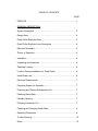
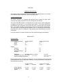
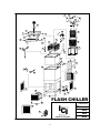
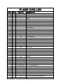
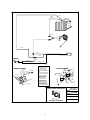
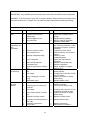
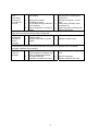
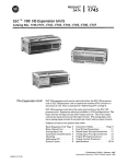
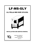
"FLASH CHILLER"
VLM-FC
Installation and Service Manual
REMOTE
SELF CONTAINED
ICI
INTERNATIONAL CARBONIC INC.
16630 KOALA DR.
ADELANTO, CA. 92301
IMPORTANT:
This manual is a guide for installing, operating,
servicing and maintaining this equipment. Refer to Table of Contents
for page location of detailed information to answer questions that
arise during installation, operating, service and maintenance, or
installation of this equipment.
TABLE OF CONTENTS
PAGE
PREFACE ............................................................................................1
GENERAL DESCRIPTION
System Description...............................................................................2
Design Data..........................................................................................2
Flash Chiller Exploded View .................................................................3
Flash Chiller Exploded View Description ..............................................4
Electrical Schematic .............................................................................5
Theory of Operation..............................................................................6
Installation ............................................................................................6
Unpacking and Inspection ....................................................................6
Selecting Location ................................................................................6
Location Recommendations for Flash Chiller .......................................6
Install Drain Line...................................................................................6
Electrical Requirements........................................................................7
Preparing System for Operation ...........................................................7
Preparing and Starting Refrigeration Unit .............................................7
Checking Water Bath............................................................................7
Periodic Cleaning .................................................................................7
Cleaning Condenser Coil......................................................................7
Checking and Changing Water Bath ....................................................8
Sanitizing Procedures...........................................................................9
Trouble Shooting ..................................................................................10
Notes ....................................................................................................12
PREFACE
INTERNATIONAL CARBONIC INC. has enjoyed over 52 years of
manufacturing excellence in the field of carbonation and in the beverage
related industry. We have had a long and proud history with quality as our
standard and innovation as our goal. Originally started just after World
War II in Canfield, Ohio as Carbonic Dispensers. We enjoyed patents on
the first Sodajet type carbonator.
This method of carbonation
instantaneously carbonated the water to 100% saturation. We developed
the first patented dispensing valve to dispense bulk beverage with
carbonation equal to or in excess of bottled beverages. A valve with three
flavors and soda was another first. We were the first to incorporate the
total postmix package, i.e., carbonation, refrigeration, and the ability to
dispense from one self contained unit. We have pioneered many such
firsts and will continue to develop advanced systems for the future, such
as electronic interrogatable portion controls to electronic liquid level
controls.
We hope you enjoy this piece of equipment that has been produced to
give many years of trouble free service. We thank you for your purchase
and hope we may serve you in the future.
1
CHAPTER I
GENERAL DESCRIPTION
This chapter gives the description, theory of operation, and design data for the FLASH
CHILLER and FLASH CHILLER-3/4, and related components.
SYSTEM DESCRIPTION
The FLASH CHILLER is a complete self-contained remote cooling unit which when
combined with related components, will cool and dispense ice-cold beer.
The FLASH CHILLER consists of a condensing unit, a water reservoir, beer cooling coils,
an agitator pump housed in an all stainless steel cabinet. The FLASH CHILLER is
manufactured with all stainless steel construction and is insulated with polyurethane
foam. The FLASH CHILLER is manufactured in remote or self-contained configurations.
The Flash Chiller is manufactured as a standard 1/2 H.P. condensing unit and can be
manufactured in a 3/4 H.P. configuration. Both models can be manufactured in a remote
configuration.
For proper function the FLASH CHILLER must have an electrical supply and drainage.
DESIGN DATA
COOLING UNIT
Overall cabinet dimensions:
Height
Width
Depth
Weights:
Shipping
Dry weight
Operational Weight
Ice Bank
FLASH CHILLER
FLASH CHILLER 3/4
45 5/8”
22”
24 1/2”
47 5/8”
22”
24 1/2”
228
193
379
90
255
220
406
90
Capacities:
Unit water bath (no ice bank)
Refrigerant requirement (R-134-A)
1/2 H.P. 285
Ambient operating temperature
22.5 gallons
3/4 H.P. 331 grams
40 F to 100 F.
Electrical Requirements: The cooling unit requires a 115 VAC 60 Hertz or 220 VAC 50 Hertz
single-phase power circuit. Please notify the factory or factory representative if a deviation of
this requirement is required.
Circuit Ampacity
Condensing Unit
Agitator
FLASH CHILLER
110VAC
220VAC
FLASH CHILLER 3/4
110VAC
220VAC
10.2 Amps
8.8 Amps
1.4 Amps
11.5 Amps
10.1 Amps
1.4 Amps
2
5.1 Amps
4.4 Amps
.7 Amps
5.8 Amps
5.1 Amps
.7 Amps
2
1
3
4
6
5
7
19
3
21
3
9
8
10
3
3
11
13
14
12
20
18
22
16
23
15
17
24
25
29
3
30
28
26
31
27
3
36
32
32
33
35
34
37
FLASH CHILLER
INTERNATIONAL CARBONIC INC.
38
ICI
32
39
ADELANTO, CALIFORNIA
3
TITLE
FLASH CHILLER
DATE
2/23/00
DRN. BY
CHK. BY
APPR. BY
GLW
GLW
GLW
FLASH CHILLER
SYM
QTY
PART NO.
DESCRIPTION
1
1
S-416
AGITATOR/COIL POSITIONING BRACKET
2
1
S-417
WASTE DRAIN POSITIONING BRACKET
3
1
A-20
SCREW, 8-32 X 3/8 T.H., S.S.
4
2
F-4
5
1
S-850
6
1
42-1020-80
7
1
S-418
RISER
8
1
S-419
RISER STIFFENER
9
1
S-420
MUG REST
SCREW
AGITATOR/CIRCULATOR PUMP
TWO FAUCET BEER TOWER
10
1
.....
TOWER JAM NUT
11
1
S-421
TOP
12
1
S-422
WASTE DRAIN ASSY.
13
4
S-1323
EVAPORATOR GUIDE WEDGE
14
4
S-499
EVAPORATOR COIL RETAINER
15
4
S-423
EVAPORATOR SUPPORT BRACKET
16
1
S-409
9" ACCUMULATOR
17
1
S-497
EVAPORATOR ASSEMBLY
18
1
.....
1/8 CAP TUBE, 10.5
19
1
S-513-A
ICE BANK CONTR0L
20
1
S-424
ICE BANK BULB BRACKET
21
1
S-425
#1 COIL 102 FEET 5/16 S.S. TUBING
22
1
S-426
#2 COIL 118 FEET 5/16 S.S. TUBING
23
1
S-427
COIL BASKET
24
1
S-428
STANDPIPE
25
1
S-429
BUCKET COMPLETE
26
1
S-430
DRAIN OUTLET, WASTE
27
1
S-489
DRAIN OUTLET, STANDPIPE
28
1
S-432
CABINET SHELL ONLY
29
4
S-46
BUSHING
30
1
S-491
REAR LINE COVER
31
1
S-433
REAR PANEL
32
3
S-434
SIDE, AND FRONT PANELS
33
1
AKA7437YXAXA
1/2 H.P. CONDENSING UNIT
AKA4476YXA
AJA7465YXAXG
AJA7461YXA
1/2 COMPRESSOR ONLY
3/4 H.P. CONDENSING UNIT
3/4 COMPRESSOR ONLY
34
1 SET
S-854
LEGS
35
1
P0003
2 X 4 "J" BOX WITH LID
36
1
P0004
2 X 4 "J" LID
37
1
VDS-16P-110
COMPRESSOR PROTECTOR 110 V.
VDS-16P-230
COMPRESSOR PROTECTOR 230 V.
38
2
A-46
39
1
E-141-12
5/16 X 18 FLANGE WHIZ LOCK SCREW, 3/4"
CORD
4
BLACK
BLACK
RIBBED
WHITE
BLACK
BLACK
BLACK
GREEN
WHITE
GREEN
BLUE
BROWN
GREEN/YELLOW
AKA7437YXAXA
AJA7465YXAXG
ELECTRICAL FIELD WIRING
AND INSTRUCTIONS
IDENTIFICATION RIB
(NEUTRAL)
POWER CORD
(GROUND TYPE)
COMP.
TERMINALS
MUST BE COPPER CONDUCTORS
ONLY.
S
R
OVERLOAD
1
3
C
1. INCOMING POWER LEADS
BLACK
RED
RUN CAPACITOR
YELLOW
IF USED
S
M
UP
RED
R
5
REGARDLESS OF LOCATION.
L
FAN (CONDENSER)
RELAY
BLACK OR BLUE
S
2
6
1
4
CONNECT LEADS TO SAME
NUMBERED TERMINALS,
2
3
1
C
RELAY
3. WHEN T.P.CO. APPROVED
ALTERNATE RELAY IS USED.
G
1
POWER LEADS FROM
DISCONNECT SWITCH
OVERLOAD
4. A JUMBER WIRE MAY BE
CONNECTED BETWEEN #4 &
#6 TERMINALS TO DISTRIBUTE
WIRES FOR EASE OF WIRING.
THE #4 AND #6 TERMINALS ARE
YELLOW
COMPRESSOR TERMINALS
GROUNDING SCREW
CONTROL BOX
START CAPACITOR
2. CONNECT INCOMING GROUND
LEAD TO GREEN GROUND SCREW.
LOW PRESSURE
CONTROL
START CAPACITOR
FAN (CONDENSER)
W/ BLEEDER RESISTOR
WIRINGTERMINALS WITH NO
INTERNAL CONNECTION TO RELAY.
INTERNATIONAL CARBONIC INC.
ICI
ADELANTO, CALIFORNIA
5
TITLE
FLASH CHILLER
WIRING DIAGRAM
DATE
11/1/05
DRN. BY
CHK. BY
APPR. BY
GLW
THEORY OF OPERATION
The FLASH CHILLER was designed to cool and dispense ice-cold beer.
The water bath holds approximately 22.5 gallons of water. A certain amount of this water
will be transformed into ice, approximately 100 pounds. This water reserve and ice bank
will act as a reservoir for refrigeration. This reserve is utilized during peak periods when
the BTU output of the compressor is not sufficient to meet the demand of the draw.
INSTALLATION
This chapter covers unpacking and inspection, selecting location, installing FLASH
CHILLER and related components, connecting water inlet and electrical requirements.
UNPACKING AND INSPECTION
Upon receiving unit, immediately remove unit from shipping carton and inspect for
shipping damage.
NOTE: Before leaving the factory all FLASH CHILLER units were carefully inspected and
the carrier has accepted and signed for them. Any damage or irregularities should be
noted at the time of delivery and immediately reported to delivering carrier. Request a
written inspection report from claims inspector to substantiate any necessary claim. File
claim with delivering agency, not International Carbonic Inc.!
SELECTING LOCATION
IMPORTANT: Ambient temperature for FLASH CHILLER should not exceed 100
degrees “F”. Operation of FLASH CHILLER in ambient above 100 degrees “F” can and
will contribute to early failure of condensing unit and poor quality of finished product.
LOCATION RECOMMENDATIONS FOR FLASH CHILLER
1.
Position unit as close as possible to proper electrical source.
2.
Position unit with a minimum of 2” space between bulkhead and cabinet for sufficient
ventilation. Allow enough space between ceiling and unit for lid removal.
3.
Position unit as close as possible to proper drainage.
4.
Place FLASH CHILLER in position. Make sure sufficient space between bulkheads,
walls and overheads is available for proper air circulation around cooling unit.
INSTALL DRAIN LINE
1.
Connect drain lines on FLASH CHILLER unit with drain using 3/4” I.D. clear plastic pipe
or 3/4” PVC to nearest outlet.
2.
Do not reduce drain connection from cabinet outlet.
3.
Be sure all connections are watertight.
6
ELECTRICAL REQUIREMENTS:
The FLASH CHILLER requires a 120 VAC, single phase at 60 Hertz or 230 VAC, single phase
at 50-hertz power circuit, and must be wired in accordance with N.E.C. or local ordinance.
NOTE: Check CHAPTER I for running amperage and connect to appropriate electrical
circuit.
PREPARATION
All previous steps should be understood and carried out before proceeding.
PREPARING SYSTEM FOR OPERATION
PREPARING AND STARTING REFRIGERATION UNIT
1. FLASH CHILLER refrigeration is pre-set at factory and ready to operate.
2. Remove lid.
3. Fill water bath with clean water until water runs out of drain standpipe, (S-428).
4. Plug FLASH CHILLER power cord into electrical receptacle box. Two things will
happen immediately. One, the agitator will come on and the compressor protector yellow
light will come on. The yellow compressor protector light will come on only if proper
voltage is supplied to the FLASH CHILLER. In approximately 3 minutes the green light
will illuminate and the yellow light will de-energize. At this time make sure compressor
and condenser fan motor. The process of cooling the water bath will now commence.
With ambient and water temperature of 75 degree “F” initial pull down or formation of
complete ice bank will take approximately 7 hrs. When full ice bank has been formed,
compressor and condenser fan motor will stop. Agitator will continue to operate,
circulating water in water bath.
CHECKING WATER BATH
Periodically check water level in water bath. If it is low more water should be added as
instructed for maximum product cooling. This dehydration will normally not occur in
normal temperate climate zones. With normal humidity the opposite will occur therefore
a condensate drain is installed. Any extra water in the water bath will exit the unit via the
drain outlet. When unit is building it's first ice bank it is normal to have water overflow the
into the overflow standpipe and out drain hose.
PERIODIC CLEANING
Periodically wash all external surfaces of FLASH CHILLER cabinet, rinse with clean
water, and then wipe dry with a clean soft cloth. DO NOT USE ABRASIVE TYPE
CLEANERS.
CLEANING CONDENSER COIL
IMPORTANT: Air circulation through the condenser coil is required to cool the
compressor. Air is drawn in through grills on the front of the FLASH CHILLER, through
condenser coil and exhausted out vents and sides of FLASH CHILLER. Restricting air
circulation through the FLASH CHILLER will decrease its cooling capacity.
7
NOTE: Cleaning condenser coil should be done during non-use periods.
1. Unplug refrigeration unit power cord from electrical socket.
2. Remove service panels.
3. Vacuum or use a soft brush to clean fins of condenser coil. Use low-pressure
compressed air or C02 gas to blow through condenser fins. This should only be
performed after normal business hours to prevent dust contamination. A damp cloth on
backside of condenser coil will prevent some dust contamination
4. Replace service panels.
S. Plug FLASH CHILLER power cord in electrical socket.
CHECKING / CHANGING WATER BATH
Periodically check water level in water bath. If it is low, more water should be added for
maximum product cooling. Before adding more water, water bath and ice bank should be
checked for excessive mineral deposit build up.
NOTE:
The water in water bath should be changed and all components in water bath
should be cleaned as often as necessary to keep it clean. A convenient time to perform
this operation is when the system is being sanitized.
1. Unplug refrigeration unit power cord from electrical socket.
2. Remove lid from unit.
3. Look down into water bath (if necessary, use flashlight) and inspect water bath, ice
bank and all components for cleanliness. Water, ice bank and all components should be
clear and free of foreign particles. If ice bank is clear of foreign particles, it does not have
to be melted down. Proceed to step 10 if foreign particles are present in the ice bank,
proceed to step 4.
4. Siphon out water with short hose or pull out over flow standpipe.
5. Allow ice bank to melt. Hot water may be used to speed melting.
CAUTION:
Never use an ice pick or other sharp instruments to remove ice from evaporator
coil. Such practice can result in puncture to the refrigeration circuit.
6. Use fiber brush and carefully clean mineral deposit from all components.
7. Wash evaporator coil with a mild soap solution. Copper cleans well with mild solution
of citric acid (1 cup of citric acid for 2 gallons of water). Stainless steel cleans well with
carbonated water. Then rinse with clean water.
6. Rinse out water bath with clean water until water running out of siphon hose is clean.
9. Insert standpipe in drain hole
10. Fill water bath to top of standpipe.
11. Replace lid.
12. Plug refrigeration unit power cord in electrical socket.
8
SANITIZING PROCEDURES
Your local health department rules and general area cleanliness should determine the frequency at which
the unit should be sanitized.
EQUIPMENT REQUIRED:
1.
2.
3.
4.
5.
Stainless Steel containers (product tanks), or large volume container.
CO2 Supply if applicable (Same as used with dispensing unit).
Cleaning Agent.
Sanitizing Solution.
Phenolphthalein.
NOTE: One recommended cleaning agent and sanitizing agent is manufactured by:
MT. HOOD CHEMICAL CORP.
4444 N.W. Yeon Avenue
Portland, Oregon 97210
Trade names are: STAR - CHLORINATED CLEANER
CROWN - 12.5% SODIUM HYPOCHLORITE BLEACH
Use STAR at 18 oz. per 1 gallon of water yields 2% Sodium Hydroxide Solution.
Use Crown at 2 ounce per 9 gallons of water (gives 200 PPM of available chlorine) at a minimum contact
time of 10 minutes.
1. Disconnect syrup containers and remove product from tubing by purging with carbon dioxide or
flushing with warm water.
2. Visually inspect valve by removing nozzle and inspecting nozzle and valve cavity. Clean nozzle with
cleaning agent, then sanitizing solution, then with potable water. Inspect valve cavity and if dirty
clean with soft bristle brush. Clean exteriors of valve with a soft clothe and warm water. Replace
valve nozzle then go to step #3.
3. Fill syrup lines with a caustic-based (low sudsing, non-perfumed, and rinsed) detergent solution,
(STAR). The solution should be prepared in accordance with the manufacturers recommendations,
but should be at least 2 percent sodium hydroxide. Make sure the syrup lines are completely filled
and allow standing for at least 10 minutes.
4. Flush the detergent solution from the syrup lines with clean water. Continue rinsing until testing with
phenolphthalein shows that the rinse water is free of residual detergent.
5. Fill the syrup lines with a low PH (7.0) chloride solution containing maximum 200-PPM chlorine.
Make sure that lines are completely filled and allow standing for 30 minutes.
6. Reconnect syrup containers and ready Unit for operation.
7. Draw drinks to refill syrup lines and flush the chloride solution from the dispenser.
8. Taste the beverage to verify that there is no off taste.
9
TROUBLE SHOOTING
IMPORTANT: Only qualified personnel should service the FLASH CHILLER unit and components.
WARNING: To avoid personal injury and or property damage, always disconnect electrical power.
Disconnect all beer lines. If repairs are to be made to system, bleed pressure before proceeding.
FLASH CHILLER
Trouble
Frozen water
bath
Cooling or
condensing unit
nonoperational
Agitator motor
not operating
Probable Cause
1.
2.
1.
2.
3.
4.
Bad ice bank control.
Refrigerant leak causing
undercharge.
Defective agitator motor.
Dirty water bath.
1.
No electrical power.
1.
2.
3.
Defective ice bank control.
Dirty condenser unit.
2.
3.
4.
Improper voltage/amperage
4.
5.
Loss of refrigerant.
5.
6.
7.
8.
Bad overload and relay.
Compressor bad.
Restriction (pinched or crimped
line).
Agitator propeller obstructed or
lost.
Low voltage.
6.
7.
8.
Loose, unplugged, or broken
wiring.
Bad agitator motor.
No power source.
3.
Electrical power to cooling unit
turned off.
Low voltage.
2.
Loose, disconnected, or broken
wire.
Inoperative ice bank control.
4.
5.
Voltage must be at least 110 V at
compressor terminals at start.
Tighten connection or replace
broken wiring.
Replace ice bank control.
Inoperative overload protector or
start relay.
Inoperative compressor.
Full ice bank.
6.
Replace defective part.
7.
8.
Replace compressor.
Refrigeration not called for.
1.
2.
3.
Compressor
does not
operate
Remedy
4.
1.
2.
3.
4.
5.
6.
7.
8.
3.
4.
10
1.
2.
4.
1.
3.
Replace bad ice bank control.
Repair leak, evacuate and recharge.
Replace defective agitator.
Melt ice, empty & clean bath.
Replenish w/fresh water.
Plug power cord into electrical
box. Check on/off switch. Check
Compressor Protector, replace if
necessary.
Replace ice bank control.
Clean condenser unit w/vacuum
cleaner.
Check for proper
voltage/amperage.
Repair leak and replenish
refrigerant.
Replace overload and relay
Replace compressor.
Repair, straighten or replace
defective line.
Remove obstruction or reAttach propeller.
Voltage must be at least 110/220
volt at terminals.
Tighten connection or replace
broken wiring.
Replace agitator motor.
Plug power cord to electrical box.
Check line voltage.
Turn on power switch to unit.
Compressor
works
continuously
but does not
form sufficient
ice bank
1.
Cooling capacity is exceeded by
over drawing.
Reduce amount of drinks taken
per given time of install higher
volume unit.
2. Cooling unit located in
2. Relocate cooling unit. Or cool
excessively hot area.
area.
3. Air circulation through condenser
3. Check and if necessary, clean
coil is restricted
condenser coil.
4. Loss of refrigerant or in-sufficient
4. Repair leak and/or recharge with
charge.
sufficient refrigerant.
Note: Ice bank freezes from bottom of evaporator upward. A refrigerant leak or insufficient charge
might show ice at bottom and not at top of evaporator.
Compressor will 1. Ice bank control capillary tube
1. Replace ice bank control.
not stop after
kinked or broken.
2. Ice bank control stuck in closed
2. Replace ice bank control.
sufficient ice
position.
bank is
produced
Note: During overload protector shut off condenser fan motor will continue to work. Otherwise,
troubleshooting condenser fan motor problems is the same as “Compressor does not operate”,
paragraph in addition to the following.
Condenser fan
1. Electrical cord loose or
1. Tighten connections or replace
motor not
disconnected from condenser fan
cord.
operating
motor or compressor terminals.
2. Fan blade obstructed.
2. Remove obstruction.
3. Inoperative condenser fan motor.
3. Replace condenser fan motor.
11
1.
NOTE SECTION
Frequently Called Numbers:
__________________________________
____________________________
__________________________________
____________________________
__________________________________
____________________________
__________________________________
____________________________
__________________________________
____________________________
__________________________________
____________________________
CO2 SETTINGS:
High Pressure ________________________ PSI
Low Pressure ________________________ PSI
_____________________________________
__________________________________
_____________________________________________________________________________________________
_____________________________________________________________________________________________
_____________________________________________________________________________________________
_____________________________________________________________________________________________
_____________________________________________________________________________________________
___________________________________________________
_____________________________________________________________________________________________
_____________________________________________________________________________________________
_____________________________________________________________________________________________
_____________________________________________________________________________________________
_____________________________________________________________________________________________
___________________________________________________
12