1
PCM-500i
PLASMA CUTTING
CONSOLE/POWER SOURCES
with CE Compliances
220 V, 50 Hz, 1-Phase
220 V, 50 Hz, 3-Phase
400 V, 50 Hz, 3-Phase
Service Manual
558000-891
9712
WARNING
ARC WELDING AND CUTTING CAN BE INJURIOUS TO YOURSELF AND OTHERS. TAKE PRECAUTIONS WHEN WELDING. ASK FOR YOUR EMPLOYERS SAFETY PRACTICES WHICH SHOULD
BE BASED ON MANUFACTURERS HAZARD DATA.
ELECTRIC SHOCK - Can kill
l
Install and earth the welding unit in accordance with applicable standards.
l
Do not touch live electrical parts or electrodes with bare skin, wet gloves or wet clothing.
l
Insulate yourself from earth and the workpiece.
l
Ensure your working stance is safe.
FUMES AND GASES - Can be dangerous to health
l
Keep your head out of the fumes
l
Use ventilation, extraction at the arc, or both, to keep fumes and gases from your breathing zone
and the general area.
ARC RAYS - Can injure eyes and burn skin.
l
Protect your eyes and body. Use the correct welding screen and filter lens and wear protective
clothing.
l
Protect bystanders with suitable screens or curtains.
FIRE HAZARD
l
Sparks (spatter) can cause fire. Make sure therefore that there are no inflammable materials nearby.
NOISE - Excessive noise can damage hearing
l
Protect your ears. Use ear defenders or other hearing protection
l
Warn bystanders of the risk.
MALFUNCTION - Call for expert assistance in the event of malfunction.
READ AND UNDERSTAND THE INSTRUCTION MANUAL BEFORE INSTALLING OR OPERATING.
PROTECT YOURSELF AND OTHERS!
TABLE OF CONTENTS
SECTION 1
SECTION 2
SECTION 3
SECTION 4
SPECIFICATIONS ............................................................................................................ 3
MAINTENANCE ................................................................................................................ 4
General, Inspection & Cleaning, Flow Switch
TROUBLESHOOTING ...................................................................................................... 5
Troubleshooting, Trouble Shooting Guide, Sequence of Operation,
Schematic and Wire Diagrams
REPLACEMENT PARTS ................................................................................................ 22
Maintenance and Repair work should be performed by an experienced person, and
electrical work only by a trained electrician. Do not permit untrained persons to
inspect, clean, or repair equipment. Use only recommended replacement parts.
For installation and operation instructions, see 558000-879 (F-15-417).
2
SECTION 1
SPECIFICATIONS
Table 1-1. PCM-500i Specifications
Rated
Output
40% Duty Cycle*
35 A @ 120 V dc
60% Duty Cycle*
30 A @ 120 V dc
100% Duty Cycle*
22 A @ 120 V dc
Output Current Range
10 to 35 Amperes
Open Circuit Voltage
265 V dc Nominal
Rated Primary Input
@
35 A @ 120 VDC Output
200 VAC, 1-Phase
220 VAC, 3-Phase
30/25 A, 50/60 Hz
14 A/Phase, 50/60 Hz
380/415 VAC, 3-Phase
8/7.5 A/Phase, 50/60 Hz
Power Factor @ 35 Amperes Output
81% (1-Phase)/94% (3-Phase)
Efficiency @ 35 Amperes Output
90% (Typical)
Current Capacity
PT-31XL
50 A DCSP
Air Requirements
PT-31XL
120l/min at 5.5 bar
Length
Height
Width
490mm
452mm**
218mm
Dimensions of PCM-500i
Weight (less torch, work cable)
23 kg
* Duty cycle is based on a 10-minute period; therefore, a 40% duty cycle means the machine may operate for 4 minutes with a cool down period of 6 minutes;
a 60% duty cycle means the machine may operate for 6 minutes with a cool down period of 4 minutes; a 100% duty cycle means the machine may operate
continuously.
** Includes 56 mm high handle.
3
SECTION 2
MAINTENANCE
2.1 GENERAL
H.
If this equipment does not operate properly, stop
work immediately and investigate the cause of the
malfunction. Maintenance work must be performed
by an experienced person, and electrical work by a
trained electrician. Do not permit untrained persons
to inspect, clean, or repair this equipment. Use only
recommended replacement parts.
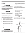
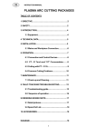
2.3 FLOW SWITCH (FIGURE 2-1)
When excessive contamination is found in the air, the
flow switch (FS) should be removed, disassembled and
cleaned as follows:
Be sure that the wall disconnect switch or wall
circuit breaker is open before attempting any inspection or work inside of the PCM-500i.
2.2 INSPECTION AND CLEANING
Frequent inspection and cleaning of the PCM-500i is
recommended for safety and proper operation. Some
suggestions for inspecting and cleaning are as follows:
A.
Check work cable to workpiece connection.
B.
Check safety earth ground at workpiece and at
power source chassis.
C.
Check heat shield on torch. It should be replaced
if damaged.
D.
Check the torch electrode and cutting nozzle for
wear on a daily basis. Remove spatter or replace
if necessary.
E.
Make sure cable and hoses are not damaged or
kinked.
F.
Make sure all fittings and ground connections are
tight.
With all input power disconnected, and wearing
proper eye and face protection, blow out the inside
of the PCM-500i using low-pressure dry compressed air.
A.
Ensure the system is shut down and there is no
trapped air under pressure in the piping.
B.
Remove the piston plug.
C.
Remove the spring (FS-4 only). Use care when
handling spring to prevent distortion.
D.
Remove the piston.
E.
Clean all parts with cleaning agent.
NOTE
Ensure cleaning agent does not contain solvents
which can degrade polysulfone. Warm water and
detergent is recommended for cleaning. Allow all
parts to dry thoroughly before reassembly.
Reassemble the flow switch in reverse order.
PISTON PLUG
SPRING
PISTON
FLOW SWITCH
Water or oil occasionally accumulates in compressed
air lines. Be sure to direct the first blast of air away
from the equipment to avoid damage to the PCM500i.
Figure 2-1. Disassembly / Assembly of Flow Switch
4
SECTION 3
TROUBLESHOOTING
referring to the sequence of operations and electrical
schematic diagram (Figure 3-1) and checking the various components. A volt-ohmmeter will be necessary for
some of these checks.
3.1 TROUBLESHOOTING
ELECTRIC SHOCK CAN KILL! Be sure that all primary power to the machine has been externally
disconnected. Open the line (wall) disconnect switch
or circuit breaker before attempting inspection or
work inside of the power source.
Voltages in plasma cutting equipment are high
enough to cause serious injury or possibly death. Be
particularly careful around equipment when the covers are removed.
Check the problem against the symptoms in the following troubleshooting guide. The remedy may be quite
simple. If the cause cannot be quickly located, shut off
the input power, open up the unit, and perform a simple
visual inspection of all the components and wiring.
Check for secure terminal connections, loose or burned
wiring or components, bulged or leaking capacitors, or
any other sign of damage or discoloration.
NOTE
Before checking voltages in the circuit, disconnect the
power from the high frequency generator to avoid damaging your voltmeter.
The cause of control malfunctions can be found by
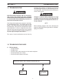
3.2 TROUBLESHOOTING GUIDE
A.
Difficult Starting.
• Change electrode
• Change nozzle
• Check for good, clean connection of work lead to workpiece
• Check air pressure (4.5 -5.2 bar)
• Check torch power cable for continuity
Depress torch switch. After 2 seconds, is there a pilot arc?
Yes
No
Repair power
source
Repair/replace
high frequency
unit
5
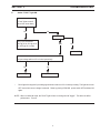
SECTION 3
B.
TROUBLESHOOTING
No Air
Is air hose connected?
Yes
No
Connect
Is air adjusted to 4.5 - 5.2 bar?
Yes
No
Adjust
Does air come on with air check switch?
Yes
No
Check continuity of torch switch
OK
No
•
•
•
•
No electrode in torch
No valve pin in torch
Replace electrode
Replace valve pin
Replace torch switch
Repair power source
6
SECTION 3
C.
TROUBLESHOOTING
Air does not shut off
Is air check switch OFF?
Yes
No
Turn switch OFF
Does arc start when nozzle contacts work without depressing torch switch?
Yes
No
Check for short in torch switch
Does air flow even when PCM-500i power switch is OFF?
Yes
Replace
solenoid valve
No
Repair power
source
7
SECTION 3
D.
TROUBLESHOOTING
White "Power" light not energized.
Is main 220 or 400 volt switch ON?
Yes
No
Turn on main disconnect
No
Insert plug in receptacle
Is plug in receptacle?
Yes
Is cooling fan turning?
Yes
No
Replace
pilot light
Check voltage at receptacle and input power line
Yes
No
Check main fuses
Faulty power
switch on PCM-500i
8
SECTION 3
E.
TROUBLESHOOTING
Amber "FAULT" light ON.
Is the unit overheated?
("Fault" lights turns off
when Unit cools down.)
Yes
No
Is air flowing?
Duty cycle exceeded:
40% @ 35 A, 60% @ 30 A,
Yes
No
or 100% @ 22 A output
Section 3.2.B
Is input voltage within ±15% of units input rating?
Yes
Adjust voltage •
•
No
Repair power source
Fault light will energize if input voltage goes below or above ±15% of units input rating. The light will not turn
OFF even when correct voltage is restored. Reset by placing PCM-500i power switch OFF and then ON
again.
NOTE: When in LOCK-IN mode, the FAULT light will turn on during second "trigger". This does not affect
performance. Turn off.
9
SECTION 3
TROUBLESHOOTING
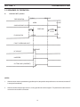
3.3 SEQUENCE OF OPERATION
A.
LOCK-IN "OFF" position
PUSH
TORCH SWITCH
RELEASE
OPEN
CLOSE
GAS SOLENOID VALVE
2 SEC.
PREFLOW
10 SEC
Postflow
FLOW SWITCH
OPEN
CLOSE
FAULT OVERLOAD LIGHT
ENERGIZE
HF CIRCUIT
INVERTER
CUTTING ARC (CURRENT)
NOTES:
1.
When the torch switch is pushed during postflow period, the postflow and preflow times are canceled, and the HF
is energized immediately.
2.
When the amber fault pilot light comes on, cutting operation should be stopped. The postflow time starts from the
moment the torch switch is released.
10
SECTION 3
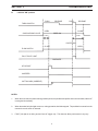
B.
TROUBLESHOOTING
LOCK-IN "ON" position
PUSH
RELEASE
PUSH
RELEASE
TORCH SWITCH
OPEN
CLOSE
GAS SOLENOID VALVE
PREFLOW
10 SEC
2 SEC.
Postflow
POSTFLOW
CLOSE
OPEN
FLOW SWITCH
FAULT PILOT LIGHT
ENERGIZE
HF CIRCUIT
INVERTER
CUTTING ARC (CURRENT)
NOTES:
1.
When the torch switch is pushed during postflow period, the postflow and preflow times are canceled, and the HF
is energized immediately.
2.
When the amber fault pilot light comes on, cutting operation should be stopped. The postflow time starts from the
moment the torch switch is released.
3.
FAULT pilot light is on during second "turn-off" trigger only. This does not affect performance in any way.
11
D-36704-B
12
Figure 3-1. Schematic Diagram PCM-500i, 220 Vac, 50/60 Hz, 1-Phase
D-36703-B (Sheet 1)
13
Figure 3-2. Wiring Diagram - PCM-500i 220 Vac, 50/60 Hz, 1-Phase (Sheet 1 of 2)
D-36703-B (Sheet 2)
14
Figure 3-2. Wiring Diagram - PCM-500i 220 Vac, 50/60 Hz, 1-Phase (Sheet 2 of 2)
D-36530-D
15
Figure 3-3. Schematic Diagram - PCM-500i 220 Vac, 50/60 Hz, 3-Phase
D-36531-D (Sheet 1)
16
Figure 3-4. Wiring Diagram - PCM-500i 220 Vac, 50/60 Hz, 3-Phase (Sheet 1 of 2)
D-36531-D (Sheet 2)
17
Figure 3-4. Wiring Diagram - PCM-500i 220 Vac, 50/60 Hz, 3-Phase (Sheet 2 of 2)
D-36339-E
18
Figure 3-5. Schematic Diagram - PCM-500i 380/415 Vac, 50/60 Hz, 3-Phase
D-36524-D (Sheet 1)
19
Figure 3-6. Wiring Diagram - PCM-500i 380/415 Vac, 50/60 Hz, 3-Phase (Sheet 1 of 2)
D-36524-D (Sheet 2)
20
Figure 3-6. Wiring Diagram - PCM-500i 380/415 Vac, 50/60 Hz, 3-Phase (Sheet 2 of 2)
SECTION 4
REPLACEMENT PARTS
4.1 GENERAL
4.2 ORDERING
Replacement Parts are illustrated on the following figures. When ordering replacement parts, order by part
number and part name, as illustrated on the figure.
To assure proper operation, it is recommended that only
genuine ESAB parts and products be used with this
equipment. The use of non-ESAB parts may void your
warranty.
Always provide the series or serial number of the unit on
which the parts will be used. The serial number is
stamped on the unit nameplate.
21
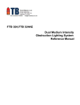
SECTION 4
REPLACEMENT PARTS
6
8
7, 14
5
9
4
2, 3
11
18
18
1
12, 14
17
19
10
13
16
15
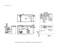
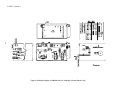
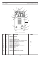
Figure 4-1. Front View, PCM-500i
ITEM
NO.
QTY.
REQ.
PART
NO.
DESCRIPTION
CIRCUIT
SYMBOL
1
2
3
4
5
6
7
8
9
10
11
12
13
14
15
16
17
18
19
1
1
1
1
1
1
1
1
1
2
1
1
1
2
4
1
1
2
1
558000590
558000372
558000373
558000591
558000562
558000592
558000385
558000384
558000383
558000593
558000594
558000698
558000178
558000596
558000552
558000597
558000536
558000132
558000599
CHASSIS
POTENTIOMETER 10K 2W
KNOB
COVER TOP
WARNING LABEL
HANDLE (Screws and Lockwashers included)
SWITCH TOGGLE DPDT 2POS 15A
LAMP, WHITE
LAMP, YELLOW
GROMMET 1.5" ID
GAUGE PRESSURE
SWITCH TOGGLE SPST 2 POS 15A
STRAIN RELIEF
SWITCH SEAL
FOOT
ACCESS DOOR
WARNING LABEL
LABEL
WARNING LABEL, HI-VOLTAGE
22
R1
S1
PL2
PL1
S2
SECTION 4
REPLACEMENT PARTS
42
41
39
40
38
37
36
52
35
43
32, 33, 34
51
44
45, 46
47
48
31
49, 50
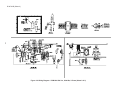
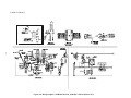
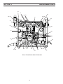
Figure 4-2. Right Side View, PCM-500i
ITEM
NO.
QTY.
REQ.
PART
NO.
31
32
33
34
35
36
37
38
39
40
41
42
43
44
45
46
47
48
49
50
51
1
1
1
2
2
1
1
1
1
1
1
1
1
1
1
1
1
1
1
2
1
1
1
558000467
558000600
558000601
558000602
558000603
558000604
558000388
558000605
558000606
558000584
558000607
558000406
558000608
558000380
558000609
558000523
558000403
558000610
52*
558000611
558000612
558000613
558000521
CIRCUIT
SYMBOL
DESCRIPTION
HI VOLTAGE TRANSFORMER
TERMINAL BLOCK 2 POS
CAPACITOR 0.1µf 250 VAC
CAPACITOR 0.01µf 1 KV
SNAP BUSHING
CONTROL TRANSFORMER
FAN AC AXIAL
AIR LINE FILTER REGULATOR
INDUCTOR POWER FACTOR CORRECTION
GROMMET -.63" ID
MAIN TRANSFORMER
INDUCTOR OUTPUT
WORK CABLE 25 FT includes CLAMP 13730862
RECEPTACLE, TWIST LOCK MIDGET
OUTPUT TERMINAL BOARD
ADAPTOR B/A 1/4 NPTM BULKHEAD
REACTOR HI FREQ
SPARK GAP ASSY includes (2) POINT 32931
STANDOFF
CAPACITOR 2500µf 15 KV
3%, 3-PH LINE REACTOR, 8A/PH (400 V)
1.5%, 3-PH LINE REACTOR, 12A/PH (220 V/3 PH)
CAPACITOR 0.047µf, 660 V
* Not shown. See Wiring Diagram for location.
23
T5
TB1
C9
C11, C12
T2
M1
L2
T1
L1
J1
T3
SG
TB2
C13, C14
L2
L2
C23
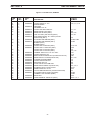
SECTION 4
REPLACEMENT PARTS
67
71
67
68, 69
65, 66
65, 66
70
64
72
63
63
73
62
61
74
85
77
75, 88
76
86
78
87
79
81
82, 83
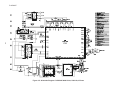
220 V, 1 Phase Power Source illustrated.
24
84
SECTION 4
REPLACEMENT PARTS
Figure 4-3. Left Side View, PCM-500i
ITEM
NO.
QTY.
REQ.
PART
NO.
61
63
64
65
66
67
5
2
1
2
2
4
2
2
1
558000405
68
69
70
71
72
73
74
75
76
77
78
79
80
81
82
83
84
85
86
87
88
2
1
2
1
2
1
1
2
1
1
1
2
1
1
1
1
4
1
1
1
1
1
1
3
558000614
558000615
558000616
558000578
558000617
558000618
558000494
558000619
558000556
558000621
558000709
558000622
558000623
558000400
558000408
558000469
558000624
558000410
558000404
558000409
558000625
558000626
558000627
558000628
558000629
CIRCUIT
SYMBOL
DESCRIPTION
CAPACITOR 0.01µF 1KV
SNAP BUSHING
HEATSINK
GROMMET 2.12" ID
CAPACITOR 1000µf 400 VDC
RESISTOR 50K 12W (220 V)
RESISTOR 10K 20W (400 V)
IGBT 50 A 600 V (PAD 951190) (220 V)
DUAL MODULE IGBT 75 A 1200 V (includes
PAD 951190) (400 V)
PC BOARD IGBT DRIVER (220 V)
PC BOARD IGBT DRIVER (400 V)
BUSBAR (230 V)
BUSBAR (400 V)
CAPACITOR 1µf 600 VDC (220 V)
CAPACITOR .5µf 1200 VDC (400 V)
CAPACITOR 1µf 630 VDC (220 V)
CAPACITOR 1µf 630 VDC (400 V)
THERMAL SWITCH D/T 176 15 A 120 V
CAPACITOR 0.22µf 1KV
MODULE INPUT BRIDGE 50 A (includes PAD 951191)
RESISTOR 50 W 10 OHM (PAD 951194)
CURRENT TRANSFORMER
CAPACITOR 20µf 400 VDC
RESISTOR 39 K 2 W
FLOW SWITCH 0.25 GPM SPST
RESISTOR 20 OHM 25 W (PAD 951193)
SOLENOID VALVE 1/4 NPT 24 VAC
ZENER DIODE 60 V 75 mA
OUTPUT BRIDGE MODULE (includes PAD 951192)
PC BOARD ASSYS START UP (hidden)
TERMINAL LUG GROUND (hidden)
EMI FILTER
VARISTOR METAL OXIDE 510 (400 V)
25
C5, 6, 7, 8, 10
C1, C2
R2
R2, R15
Q1, Q2
Q1
PCB2, PCB3
PCB3
C15, C16
C22
C3
C3, C15
TS1
C19
IBR
R7, R10
T4
C4
R9
FS
R3, 4, 5, 6
SOL1
ZD1
D1
PCB5
GND1
FN1
MOV 1, 2, 3
SECTION 4
REPLACEMENT PARTS
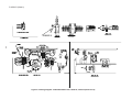
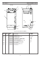
Rear View
Top View
102
114
101
103
104
113, 117
110
101
107
115
116
Figure 4-4. Top and Rear View, PCM-500i
ITEM
NO.
QTY.
REQ.
PART
NO.
DESCRIPTION
101
102
103
104
2
2
1
1
1
1
1
1
1
1
1
1
558000584
558000585
558000396
558000586
558000587
558000534
558000588
558000589
558000686
558000537
558000620
558000516
GROMMET 0.63 ID
CAPACITOR 0.22µf 250 VAC
PC BOARD SHUNT
PC BOARD ASSY CONTROL (220 V)
PC BOARD ASSY CONTROL (400 V)
ADAPTOR, AIR-WATER
CIRCUIT BREAKER 40 A (220 v, 1 ph)
CIRCUIT BREAKER 20 A (3 PH)
FUSE 3A 600VAC FAST ACTING
STRAIN RELIEF
CABLE INPUT POWER, 10 FT
FUSE HOLDER
107
110
113
115
116
117
CIRCUIT
SYMBOL
26
C17, C18
PCB4
PCB1
PCB1
CB1
CB1
F1
SECTION 4
REPLACEMENT PARTS
27
F-15-423
12/97
Printed in U.S.A.