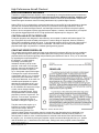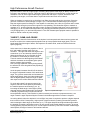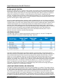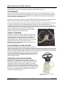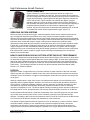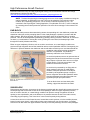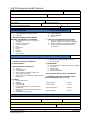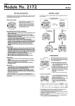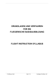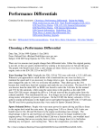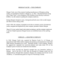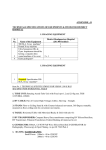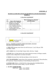
1
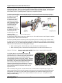
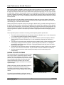
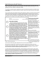
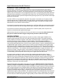
High Performance Aircraft Checkout Pilots seeking checkout in the high performance Cessna 182 will follow the normal checkout policy if the pilot has a high performance endorsement, a minimum of 100 hours of logged pilot flight time and at least 5 hours in type. If the pilot does not meet the minimum hour requirement for the high performance checkout, a Mentone Flying Club training program of not less than 5 hours in make and model (Cessna 182) for members with more than 100 hours total time, or 10 hours in make and model (Cessna 182) for members with less than 100 hours total time, along with a satisfactory signoff on the Pilot Checkout Form. If the pilot is lacking only a high performance endorsement, a Mentone Flying Club training program of not less than 5 hours in make and model (Cessna 182) is required to obtain the log book endorsement for high performance and satisfactory signoff on the Pilot Checkout Form. ChrisAir Flight Training L.L.C. Mentone Flying Club, Inc. 1 Current 2009 High Performance Aircraft Checkout PREFACE This High Performance Aircraft Checkout Packet is designed as a teaching guide for pilots transitioning to high performance aircraft. It introduces basic high performance aircraft systems and procedures, as well as provides the basic knowledge that is essential for piloting common GA high performance airplanes. This packet has been developed by ChrisAir Flight Training L.L.C. in conjunction with the Mentone Flying Club, Inc. and is derived from information found in the Airplane Flying Handbook, Handbook of Aeronautical Knowledge, Code of Federal Regulations (CFRs), Aeronautical Information Manual (AIM) and follows the recommendations of the FAA for a High Performance Aircraft Checkout. This Checkout Packet is not an all inclusive guide, but rather a starting place for basic information. It is not a substitute for proper instruction from a qualified Certified Flight Instructor (CFI). This packet should be used by the student and instructor as a teaching guide in conjunction with the Aircraft Flight Manual. Digital copy’s of this manual are found free of charge on the Mentone Flying Club Website at: http://www.mentoneflyingclub.org/aircraft/High%20Performance%20Checkout.pdf ChrisAir Flight Training L.L.C. Mentone Flying Club, Inc. 2 Current 2009 High Performance Aircraft Checkout Transition to a complex airplane or a high performance airplane should be accomplished through a structured course of training administered by a competent and qualified flight instructor. The training should be accomplished in accordance with a ground and flight training syllabus. [Figure 1] Ground Instruction Flight Instruction 1 Hour 1 Hour 1. 2. 3. Operations section of flight manual Line inspection Cockpit familiarization 1. 2. 1 Hour 1. 2. 3. Aircraft loading, limitations and servicing Instruments, radio and special equipment Aircraft systems 3. 1 Hour 1. 2. 3. Performance section of flight manual Cruise control Review Flight training maneuvers Takeoffs, landings and goarounds 1 Hour 1. 2. Emergency operations Control by reference to instruments Use of radio and autopilot 1 Hour 1. 2. Directed Practice* Short and soft-field takeoffs and landings Maximum performance operations 1 Hour As assigned by flight instructor 1 Hour As assigned by flight instructor 1 Hour -- CHECKOUT * The directed practice indicated may be conducted solo or with a safety pilot at the discretion of the instructor. Figure 1. Transition Training Syllabus. This syllabus for transition training is to be considered flexible. The arrangement of the subject matter may be changed and the emphasis may be shifted to fit the qualifications of the transitioning pilot, the airplane involved, and the circumstances of the training situation, provided the prescribed proficiency standards are achieved. These standards are contained in the practical test standards appropriate for the certificate that the transitioning pilot holds or is working towards. The training times indicated in the syllabus are based on the capabilities of a pilot who is currently active and fully meets the present requirements for the issuance of at least a private pilot certificate. The time periods may be reduced for pilots with higher qualifications or increased for pilots who do not meet the current certification requirements or who have had little recent flight experience. ChrisAir Flight Training L.L.C. Mentone Flying Club, Inc. 3 Current 2009 High Performance Aircraft Checkout HIGH PERFORMANCE AIRPLANES Transition to a high performance airplane, can be demanding for most pilots without previous experience. Increased performance and increased complexity both require additional planning, judgment, and piloting skills. Transition to these types of airplanes, therefore, should be accomplished in a systematic manner through a structured course of training administered by a qualified flight instructor. Under CFR 61.31(f), a private pilot or commercial pilot may not act as PIC of a high performance airplane (one that has more than 200 horsepower) unless he or she has received flight instruction in such an airplane from an authorized flight instructor, and that flight instructor has certified in the pilot’s logbook that he or she is competent to pilot a high performance airplane. However, this instruction is not required if the pilot has logged flight time as PIC in high performance airplanes prior to August 4, 1997. CONTROLLABLE-PITCH PROPELLER Fixed-pitch propellers are designed for best efficiency at one speed of rotation and forward speed. This type of propeller will provide suitable performance in a narrow range of airspeeds; however, efficiency would suffer considerably outside this range. To provide high propeller efficiency through a wide range of operation, the propeller blade angle must be controllable. The most convenient way of controlling the propeller blade angle is by means of a constant-speed governing system. CONSTANT-SPEED PROPELLER The constant-speed propeller keeps the blade angle adjusted for maximum efficiency for most conditions of flight. When an engine is running at constant speed, the torque (power) exerted by the engine at the propeller shaft must equal the opposing load provided by the resistance of the air. The r.p.m. is controlled by regulating the torque absorbed by the propeller—in other words by increasing or decreasing the resistance offered by the air to the propeller. In the case of a fixed-pitch propeller, the torque absorbed by the propeller is a function of speed, or r.p.m. If the power output of the engine is changed, the engine will accelerate or decelerate until an r.p.m. is reached at which the power delivered is equal to the power absorbed. In the case of a constant-speed propeller, the power absorbed is independent of the r.p.m., for by varying the pitch of the blades, the air resistance and hence the torque or load, can be changed without reference to propeller speed. This is accomplished with a constant-speed propeller by means of a governor. The governor, in most cases, is geared to the engine crankshaft and thus is sensitive to changes in engine r.p.m. The pilot controls the engine r.p.m. indirectly by means of a propeller control in the cockpit, which is Figure 2. Cessna 182 POH excerpt. connected to the governor. For maximum takeoff power, the propeller control is moved all the way forward to the low pitch/high r.p.m. position, and the throttle is moved forward to the maximum allowable manifold pressure position. To reduce power for climb or cruise, manifold pressure is reduced to the desired value with the throttle, and the engine r.p.m. is reduced by moving the propeller control back toward the high pitch/low r.p.m. position until the desired r.p.m. is observed on the tachometer. Pulling back on the propeller control causes the ChrisAir Flight Training L.L.C. Mentone Flying Club, Inc. 4 Current 2009 High Performance Aircraft Checkout propeller blades to move to a higher angle. Increasing the propeller blade angle (of attack) results in an increase in the resistance of the air. This puts a load on the engine so it slows down. In other words, the resistance of the air at the higher blade angle is greater than the torque, or power, delivered to the propeller by the engine, so it slows down to a point where the two forces are in balance. When an airplane is nosed up into a climb from level flight, the engine will tend to slow down. Since the governor is sensitive to small changes in engine r.p.m., it will decrease the blade angle just enough to keep the engine speed from falling off. If the airplane is nosed down into a dive, the governor will increase the blade angle enough to prevent the engine from overspeeding. This allows the engine to maintain a constant r.p.m., and thus maintain the power output. Changes in airspeed and power can be obtained by changing r.p.m. at a constant manifold pressure; by changing the manifold pressure at a constant r.p.m.; or by changing both r.p.m. and manifold pressure. Thus the constant-speed propeller makes it possible to obtain an infinite number of power settings. TAKEOFF, CLIMB, AND CRUISE During takeoff, when the forward motion of the airplane is at low speeds and when maximum power and thrust are required, the constant-speed propeller sets up a low propeller blade angle (pitch). The low blade angle keeps the angle of attack, with respect to the relative wind, small and efficient at the low speed. [Figure 4] At the same time, it allows the propeller to ―slice it thin‖ and handle a smaller mass of air per revolution. This light load allows the engine to turn at maximum r.p.m. and develop maximum power. Although the mass of air per revolution is small, the number of revolutions per minute is high. Thrust is maximum at the beginning of the takeoff and then decreases as the airplane gains speed and the airplane drag increases. Due to the high slipstream velocity during takeoff, the effective lift of the wing behind the propeller(s) is increased. As the airspeed increases after lift-off, the load on the engine is lightened because of the small blade angle. The governor senses this and increases the blade angle slightly. Again, the higher blade angle, with the higher speeds, keeps the angle of attack with respect to the relative wind small and efficient. For climb after takeoff, the power output of the engine is reduced to climb power by decreasing the manifold pressure and lowering r.p.m. by increasing the blade angle. At the higher (climb) airspeed and the higher blade angle, the propeller Figure 3. Propeller blade angle. is handling a greater mass of air per second at a lower slipstream velocity. This reduction in power is offset by the increase in propeller efficiency. The angle of attack is again kept small by the increase in the blade angle with an increase in airspeed. At cruising altitude, when the airplane is in level flight, less power is required to produce a higher airspeed than is used in climb. Consequently, engine power is again reduced by lowering the manifold pressure and increasing the blade angle (to decrease r.p.m.). The higher airspeed and higher blade angle enable the propeller to handle a still greater mass of air per second at still smaller slipstream velocity. At normal cruising speeds, propeller efficiency is at, or near maximum efficiency. Due to the increase in blade angle and airspeed, the angle of attack is still small and efficient. ChrisAir Flight Training L.L.C. Mentone Flying Club, Inc. 5 Current 2009 High Performance Aircraft Checkout BLADE ANGLE CONTROL Once the pilot selects the r.p.m. settings for the propeller, the propeller governor automatically adjusts the blade angle to maintain the selected r.p.m. It does this by using oil pressure. Generally, the oil pressure used for pitch change comes directly from the engine lubricating system. When a governor is employed, engine oil is used and the oil pressure is usually boosted by a pump, which is integrated with the governor. The higher pressure provides a quicker blade angle change. The r.p.m. at which the propeller is to operate is adjusted in the governor head. The pilot changes this setting by changing the position of the governor rack through the cockpit propeller control. On some constant-speed propellers, changes in pitch are obtained by the use of an inherent centrifugal twisting moment of the blades that tends to flatten the blades toward low pitch, and oil pressure applied to a hydraulic piston connected to the propeller blades which moves them toward high pitch. Another type of constant-speed propeller uses counterweights attached to the blade shanks in the hub. Governor oil pressure and the blade twisting moment move the blades toward the low pitch position, and centrifugal force acting on the counterweights moves them (and the blades) toward the high pitch position. In the first case above, governor oil pressure moves the blades towards high pitch, and in the second case, governor oil pressure and the blade twisting moment move the blades toward low pitch. A loss of governor oil pressure, therefore, will affect each differently. GOVERNING RANGE The blade angle range for constant-speed propellers varies from about 11 1/2 to 40°. The higher the speed of the airplane, the greater the blade angle range. [Figure 4] Figure 4. Blade angle range (values are approximate). The range of possible blade angles is termed the propeller’s governing range. The governing range is defined by the limits of the propeller blade’s travel between high and low blade angle pitch stops. As long as the propeller blade angle is within the governing range and not against either pitch stop, a constant engine r.p.m. will be maintained. However, once the propeller blade reaches its pitch-stop limit, the engine r.p.m. will increase or decrease with changes in airspeed and propeller load similar to a fixed-pitch propeller. For example, once a specific r.p.m. is selected, if the airspeed decreases enough, the propeller blades will reduce pitch, in an attempt to maintain the selected r.p.m., until they contact their low pitch stops. From that point, any further reduction in airspeed will cause the engine r.p.m. to decrease. Conversely, if the airspeed increases, the propeller blade angle will increase until the high pitch stop is reached. The engine r.p.m. will then begin to increase. CONSTANT-SPEED PROPELLER OPERATION The engine is started with the propeller control in the low pitch/high r.p.m. position. This position reduces the load or drag of the propeller and the result is easier starting and warm-up of the engine. During warmup, the propeller blade changing mechanism should be operated slowly and smoothly through a full cycle. This is done by moving the propeller control (with the manifold pressure set to produce about 1,600 r.p.m.) to the high pitch/low r.p.m. position, allowing the r.p.m. to stabilize, and then moving the propeller control back to the low pitch takeoff position. This should be done for two reasons: to determine whether the system is operating correctly, and to circulate fresh warm oil through the propeller governor system. It ChrisAir Flight Training L.L.C. Mentone Flying Club, Inc. 6 Current 2009 High Performance Aircraft Checkout should be remembered that the oil has been trapped in the propeller cylinder since the last time the engine was shut down. There is a certain amount of leakage from the propeller cylinder, and the oil tends to congeal, especially if the outside air temperature is low. Consequently, if the propeller isn’t exercised before takeoff, there is a possibility that the engine may overspeed on takeoff. An airplane equipped with a constant-speed propeller has better takeoff performance than a similarly powered airplane equipped with a fixed-pitch propeller. This is because with a constant-speed propeller, an airplane can develop its maximum rated horsepower (red line on the tachometer) while motionless. An airplane with a fixedpitch propeller, on the other hand, must accelerate down the runway to increase airspeed and aerodynamically unload the propeller so that r.p.m. and horsepower can steadily build up to their Figure 5. Propeller governor. maximum. With a constantspeed propeller, the tachometer reading should come up to within 40 r.p.m. of the red line as soon as full power is applied, and should remain there for the entire takeoff. Excessive manifold pressure raises the cylinder compression pressure, resulting in high stresses within the engine. Excessive pressure also produces high engine temperatures. A combination of high manifold pressure and low r.p.m. can induce damaging detonation. In order to avoid these situations, the following sequence should be followed when making power changes. When increasing power, increase the r.p.m. first, and then the manifold pressure. When decreasing power, decrease the manifold pressure first, and then decrease the r.p.m. Instructor Technique: Always keep the 3 letters (RPM) higher than (or equal to) the 2 letters (MP). Example: 2400 RPM & 23” MP. It is a fallacy that (in non-turbocharged engines) the manifold pressure in inches of mercury (inches Hg) should never exceed r.p.m. in hundreds for cruise power settings. The cruise power charts in the AFM/POH should be consulted when selecting cruise power settings. Whatever the combinations of r.p.m. and manifold pressure listed in these charts—they have been flight tested and approved by the airframe and powerplant engineers for the respective airframe and engine manufacturer. Therefore, if there are power settings such as 2,100 r.p.m. and 24 inches manifold pressure in the power chart, they are approved for use. Figure 6. RPM and Manifold Pressure Gage. With a constant-speed propeller, a power descent can be made without overspeeding the engine. The system compensates for the increased airspeed of the descent by increasing the propeller blade angles. If the descent is too rapid, or is being made from a high altitude, the maximum blade angle limit of the blades is not sufficient to hold the r.p.m. constant. When this occurs, the r.p.m. is responsive to any change in throttle setting. ChrisAir Flight Training L.L.C. Mentone Flying Club, Inc. 7 Current 2009 High Performance Aircraft Checkout Some pilots consider it advisable to set the propeller control for maximum r.p.m. during the approach to have full horsepower available in case of emergency. If the governor is set for this higher r.p.m. early in the approach when the blades have not yet reached their minimum angle stops, the r.p.m. may increase to unsafe limits. However, if the propeller control is not readjusted for the takeoff r.p.m. until the approach is almost completed, the blades will be against, or very near their minimum angle stops and there will be little if any change in r.p.m. In case of emergency, both throttle and propeller controls should be moved to takeoff positions. Many pilots prefer to feel the airplane respond immediately when they give short bursts of the throttle during approach. By making the approach under a little power and having the propeller control set at or near cruising r.p.m., this result can be obtained. Although the governor responds quickly to any change in throttle setting, a sudden and large increase in the throttle setting will cause a momentary overspeeding of the engine until the blades become adjusted to absorb the increased power. If an emergency demanding full power should arise during approach, the sudden advancing of the throttle will cause momentary overspeeding of the engine beyond the r.p.m. for which the governor is adjusted. This temporary increase in engine speed acts as an emergency power reserve. Some important points to remember concerning constant-speed propeller operation are: The red line on the tachometer not only indicates maximum allowable r.p.m.; it also indicates the r.p.m. required to obtain the engine’s rated horsepower. A momentary propeller overspeed may occur when the throttle is advanced rapidly for takeoff. This is usually not serious if the rated r.p.m. is not exceeded by 10 percent for more than 3 seconds. The green arc on the tachometer indicates the normal operating range. When developing power in this range, the engine drives the propeller. Below the green arc, however, it is usually the windmilling propeller that powers the engine. Prolonged operation below the green arc can be detrimental to the engine. On takeoffs from low elevation airports, the manifold pressure in inches of mercury may exceed the r.p.m. This is normal in most cases. The pilot should consult the AFM/POH for limitations. All power changes should be made smoothly and slowly to avoid overboosting and/or overspeeding. ENGINE COOLING SYSTEMS The burning fuel within the cylinders produces intense heat, most of which is expelled through the exhaust system. Much of the remaining heat, however, must be removed, or at least dissipated, to prevent the engine from overheating. Otherwise, the extremely high engine temperatures can lead to loss of power, excessive oil consumption, detonation, and serious engine damage. While the oil system is vital to the internal cooling of the engine, an additional method of cooling is necessary for the engine’s external surface. Most small aircraft are air cooled, although some are liquid cooled. Air cooling is accomplished by air flowing into the engine compartment through openings in front of the ChrisAir Flight Training L.L.C. Mentone Flying Club, Inc. 8 Figure 7. Cessna 182 Cowl Flaps Current 2009 High Performance Aircraft Checkout engine cowling. Baffles route this air over fins attached to the engine cylinders, and other parts of the engine, where the air absorbs the engine heat. Expulsion of the hot air takes place through one or more openings in the lower, aft portion of the engine cowling. The outside air enters the engine compartment through an inlet behind the propeller hub. Baffles direct it to the hottest parts of the engine, primarily the cylinders, which have fins that increase the area exposed to the airflow. The air cooling system is less effective during ground operations, takeoffs, go-arounds, and other periods of high-power, low-airspeed operation. Conversely, high-speed descents provide excess air and can shock cool the engine, subjecting it to abrupt temperature fluctuations. In order to give you more control over engine cooling, some airplanes are equipped with cowl flaps. Opening the cowl flaps creates a larger path for air to escape from the engine compartment, increasing the cooling airflow. [Figure 7] Operating the engine at higher than its designed temperature can cause loss of power, excessive oil consumption, and detonation. It will also lead to serious permanent damage, such as scoring the cylinder walls, damaging the pistons and rings, and burning and warping the valves. Monitoring the flight deck engine temperature instruments will aid in avoiding high operating temperature. Under normal operating conditions in aircraft not equipped with cowl flaps, the engine temperature can be controlled by changing the airspeed or the power output of the engine. High engine temperatures can be decreased by increasing the airspeed and/or reducing the power. The oil temperature gauge gives an indirect and delayed indication Figure 8. Cessna 182 POH excerpt. of rising engine temperature, but can be used for determining engine temperature if this is the only means available. Most aircraft are equipped with a cylinder-head temperature gauge which indicates a direct and immediate cylinder temperature change. This instrument is calibrated in degrees Celsius or Fahrenheit, and is usually color coded with a green arc to indicate the normal operating range. A red line on the instrument indicates maximum allowable cylinder head temperature. To avoid excessive cylinder head temperatures, increase airspeed, enrich the mixture, and/or reduce power. Any of these procedures help to reduce the engine temperature. On aircraft equipped with cowl flaps [Figure 7], use the cowl flap positions to control the temperature. Cowl flaps are hinged covers that fit over the opening through which the hot air is expelled. If the engine temperature is low, the cowl flaps can be closed, thereby restricting the flow of expelled hot air and increasing engine temperature. If the engine temperature is high, the cowl flaps can be opened to permit a greater flow of air through the system, thereby decreasing the engine temperature. ChrisAir Flight Training L.L.C. Mentone Flying Club, Inc. 9 Current 2009 High Performance Aircraft Checkout HIGHER ALTITUDE CONSIDERATIONS As stated before, the transition to a high performance aircraft can be demanding for pilots without previous experience. This increased performance can create new hazards such as flight at altitudes were supplemental oxygen is required. The following information is not provided as part of a high altitude checkout, but as a reference for the new high performance pilot. It is specifically geared toward the basic high performance capabilities of such aircraft as the Cessna 182. The information provided will only give a basic overview of oxygen systems and high altitude physiology required by a light General Aviation high performance aircraft pilot. A review of CFR 91.211(a) states that, No person may operate a civil aircraft of U.S. registry at cabin pressure altitudes above 12,500 feet (MSL) up to and including 14,000 feet (MSL) unless the required minimum flight crew is provided with and uses supplemental oxygen for that part of the flight at those altitudes that is of more than 30 minutes duration. If the aircraft is operated at cabin pressure altitudes above 14,000 feet (MSL) the required minimum flight crew must be provided with and use supplemental oxygen during the entire flight time at those altitudes. If the aircraft is operated at cabin pressure altitudes above 15,000 feet (MSL) each occupant of the aircraft must be provided with supplemental oxygen. While the above rules are set forth by the FAA, they do however recommend that pilots should avoid flying above 10,000 feet without oxygen during the day and above 8,000 feet at night. OXYGEN SYSTEMS Most light General Aviation High Performance aircraft do not have a fixed oxygen installation, thus portable oxygen equipment may need to be readily accessible during flight. The portable equipment usually consists of a container, regulator, mask outlet, and pressure gauge. Aircraft oxygen is usually stored in high pressure system containers of 1,800–2,200 psi. When the ambient temperature surrounding an oxygen cylinder decreases pressure within that cylinder decreases because pressure varies directly with temperature if the volume of a gas remains constant. If a drop in indicated pressure on a supplemental oxygen cylinder is noted, there is no reason to suspect depletion of the oxygen supply, which has simply been compacted due to storage of the containers in an unheated area of the aircraft. High pressure oxygen containers should be marked with the psi tolerance (i.e., 1,800 psi) before filling the container to that pressure. The containers should be supplied with aviation oxygen only, which is 100 percent pure oxygen. Industrial oxygen is not intended for breathing and may contain impurities, and medical oxygen contains water vapor that can freeze in the regulator when exposed to cold temperatures. To assure safety, periodic inspection and servicing of the oxygen system should be done. An oxygen system consists of a mask or cannula and a regulator that supplies a flow of oxygen dependent upon cabin altitude. Cannulas are not approved for flights above 18,000 feet. Regulators approved for use up to 40,000 feet are designed to provide zero percent cylinder oxygen and 100 percent cabin air at cabin altitudes of 8,000 feet or less, with the ratio changing to 100 percent oxygen and zero percent cabin air at approximately 34,000 feet cabin altitude. Regulators approved up to 45,000 feet are designed to provide 40 percent cylinder oxygen and 60 percent cabin air at lower altitudes, with the ratio changing to 100 percent at the higher altitude. Pilots should be aware of the danger of fire when using oxygen. Materials that are nearly fireproof in ordinary air may be susceptible to combustion in oxygen. Oils and greases may ignite if exposed to oxygen, and cannot be used for sealing the valves and fittings of oxygen equipment. Smoking during any kind of oxygen equipment use is prohibited. Before each flight, the pilot should thoroughly inspect and test all oxygen equipment. The inspection should include a thorough examination of the aircraft oxygen equipment, including available supply, an operational check of the system, and assurance that the supplemental oxygen is readily accessible. The inspection should be accomplished with clean hands and should include a visual inspection of the mask and tubing for tears, cracks, or deterioration; the regulator for valve and lever condition and positions; oxygen quantity; and the location and functioning of oxygen ChrisAir Flight Training L.L.C. Mentone Flying Club, Inc. 10 Current 2009 High Performance Aircraft Checkout pressure gauges, flow indicators and connections. The mask should be donned and the system should be tested. After any oxygen use, verify that all components and valves are shut off. OXYGEN MASKS There are numerous types and designs of oxygen masks in use. The most important factor in oxygen mask use is to insure the masks and oxygen system are compatible. Crew masks are fitted to the user’s face with a minimum of leakage and usually contain a microphone. Most masks are the oronasal type, which covers only the mouth and nose. A passenger mask may be a simple, cup-shaped rubber molding sufficiently flexible to obviate individual fitting. It may have a simple elastic head strap or the passenger may hold it to his or her face. All oxygen masks should be kept clean to reduce the danger of infection and prolong the life of the mask. To clean the mask, wash it with a mild soap and water solution and rinse it with clear water. If a microphone is installed, use a clean swab, instead of running water, to wipe off the soapy solution. The mask should also be disinfected. A gauze pad that has been soaked in a water solution of Merthiolate can be used to swab out the mask. This solution used should contain one-fifth teaspoon of Merthiolate per quart of water. Wipe the mask with a clean cloth and air dry. CANNULA TYPE MASK A cannula is an ergonomic piece of plastic tubing which runs under the nose and is often used to administer oxygen in nonpressurized aircraft. Cannulas [Figure 9] are typically more comfortable then masks and can be used up to 18,000 feet. Altitudes greater than 18,000 feet require the use of an oxygen mask. Many cannulas have a flow meter in the line. If equipped, a periodic check of the green flow detector should be part of a pilot’s regular scan. DILUTER-DEMAND OXYGEN SYSTEMS Figure 9. Cannula Type Mask Diluter-demand oxygen systems supply oxygen only when the user inhales through the mask. An automix lever allows the regulators to automatically mix cabin air and oxygen or supply 100 percent oxygen, depending on the altitude. The demand mask provides a tight seal over the face to prevent dilution with outside air and can be used safely up to 40,000 feet. A pilot who has a beard or mustache should be sure it is trimmed in a manner that will not interfere with the sealing of the oxygen mask. The fit of the mask around the beard or mustache should be checked on the ground for proper sealing. CONTINUOUS-FLOW OXYGEN SYSTEM Continuous-flow oxygen systems are usually provided for passengers. The passenger mask typically has a reservoir bag, which collects oxygen from the continuous-flow oxygen system during the time when the mask user is exhaling. The oxygen collected in the reservoir bag allows a higher aspiratory flow rate during the inhalation cycle, which reduces the amount of air dilution. Ambient air is added to the supplied oxygen during inhalation after the reservoir bag oxygen supply is depleted. The exhaled air is released to the cabin. [Figure 10] Figure 10. Continuous flow mask and rebreather bag. ChrisAir Flight Training L.L.C. Mentone Flying Club, Inc. 11 Current 2009 High Performance Aircraft Checkout PULSE OXIMETERS Figure 11. Pulse Oximeter. A pulse oximeter is a device that measures the amount of oxygen in an individual’s blood, in addition to heart rate. This non-invasive device measures the color changes that red blood cells undergo when they become saturated with oxygen. By transmitting a special light beam through a fingertip to evaluate the color of the red cells, a pulse oximeter can calculate the degree of oxygen saturation within one percent of directly measured blood oxygen. Because of their portability and speed, pulse oximeters are very useful for pilots operating in nonpressurized aircraft above 12,500 feet where supplemental oxygen is required. A pulse oximeter permits crewmembers and passengers of an aircraft to evaluate their actual need for supplemental oxygen. [Figure 11] SERVICING OXYGEN SYSTEMS Before servicing any aircraft with oxygen, consult the specific aircraft service manual to determine the type of equipment required and procedures to be used. Certain precautions should be observed whenever aircraft oxygen systems are to be serviced. Oxygen system servicing should be accomplished only when the aircraft is located outside of the hangars. Personal cleanliness and good housekeeping are imperative when working with oxygen. Oxygen under pressure and petroleum products create spontaneous results when they are brought in contact with each other. Service people should be certain to wash dirt, oil, and grease (including lip salves and hair oil) from their hands before working around oxygen equipment. It is also essential that clothing and tools are free of oil, grease, and dirt. Oxygen system servicing is not recommended during aircraft fueling operations or while other work is performed that could provide a source of ignition. Oxygen system servicing while passengers are on board the aircraft is not recommended. HEALTH AND PHYSIOLOGICAL FACTORS AFFECTING PILOT PERFORMANCE A number of health factors and physiological effects can be linked to flying. Some are minor, while others are important enough to require special attention to ensure safety of flight. In some cases, physiological factors can lead to inflight emergencies. Some important medical factors that a new high performance pilot should be aware of include hypoxia, middle ear, sinus problems and decompression sickness after scuba diving. The following information is directly from the Aeronautical Information Manual (AIM) section 8-1-2, ―Effects of Altitude‖. HYPOXIA Hypoxia is a state of oxygen deficiency in the body sufficient to impair functions of the brain and other organs. Hypoxia from exposure to altitude is due only to the reduced barometric pressures encountered at altitude, for the concentration of oxygen in the atmosphere remains about 21 percent from the ground out to space. Although a deterioration in night vision occurs at a cabin pressure altitude as low as 5,000 feet, other significant effects of altitude hypoxia usually do not occur in the normal healthy pilot below 12,000 feet. From 12,000 to 15,000 feet of altitude, judgment, memory, alertness, coordination and ability to make calculations are impaired, and headache, drowsiness, dizziness and either a sense of well-being (euphoria) or belligerence occur. The effects appear following increasingly shorter periods of exposure to increasing altitude. In fact, pilot performance can seriously deteriorate within 15 minutes at 15,000 feet. At cabin pressure altitudes above 15,000 feet, the periphery of the visual field grays out to a point where only central vision remains (tunnel vision). A blue coloration (cyanosis) of the fingernails and lips develops. The ability to take corrective and protective action is lost in 20 to 30 minutes at 18,000 feet and 5 to 12 minutes at 20,000 feet, followed soon thereafter by unconsciousness. The altitude at which significant effects of hypoxia occur can be lowered by a number of factors. Carbon monoxide inhaled in smoking or from exhaust fumes, lowered hemoglobin (anemia), and certain medications can reduce the oxygen-carrying capacity of the blood to the degree that the amount of oxygen provided to body tissues will already be equivalent to the oxygen provided to the tissues when ChrisAir Flight Training L.L.C. Mentone Flying Club, Inc. 12 Current 2009 High Performance Aircraft Checkout exposed to a cabin pressure altitude of several thousand feet. Small amounts of alcohol and low doses of certain drugs, such as antihistamines, tranquilizers, sedatives and analgesics can, through their depressant action, render the brain much more susceptible to hypoxia. Extreme heat and cold, fever, and anxiety increase the body's demand for oxygen, and hence its susceptibility to hypoxia. Hypoxia is prevented by heeding factors that reduce tolerance to altitude, by enriching the inspired air with oxygen from an appropriate oxygen system, and by maintaining a comfortable, safe cabin pressure altitude. For optimum protection, pilots are encouraged to use supplemental oxygen above 10,000 feet during the day, and above 5,000 feet at night. The CFRs require that at the minimum, flight crew be provided with and use supplemental oxygen after 30 minutes of exposure to cabin pressure altitudes between 12,500 and 14,000 feet and immediately on exposure to cabin pressure altitudes above 14,000 feet. Every occupant of the aircraft must be provided with supplemental oxygen at cabin pressure altitudes above 15,000 feet. The FAA however recommends that pilots should avoid flying above 10,000 feet without oxygen during the day and above 8,000 feet at night. SYMPTOMS OF HYPOXIA High-altitude flying can place a pilot in danger of becoming hypoxic. Oxygen starvation causes the brain and other vital organs to become impaired. One noteworthy attribute of the onset of hypoxia is that the first symptoms are euphoria and a carefree feeling. With increased oxygen starvation, the extremities become less responsive and flying becomes less coordinated. The symptoms of hypoxia vary with the individual, but common symptoms include: • Cyanosis (blue fingernails and lips) • Headache • Decreased reaction time • Impaired judgment • Euphoria • Visual impairment • Drowsiness • Lightheaded or dizzy sensation • Tingling in fingers and toes • Numbness As hypoxia worsens, the field of vision begins to narrow, and instrument interpretation can become difficult. Even with all these symptoms, the effects of hypoxia can cause a pilot to have a false sense of security and be deceived into believing everything is normal. The treatment for hypoxia includes flying at lower altitudes and/or using supplemental oxygen. All pilots are susceptible to the effects of oxygen starvation, regardless of physical endurance or acclimatization. When flying at high altitudes, it is paramount that oxygen be used to avoid the effects of hypoxia. The term ―time of useful consciousness‖ describes the maximum time the pilot has to make rational, life-saving decisions and carry them out at a given altitude without supplemental oxygen. As altitude increases above 10,000 feet, the symptoms of hypoxia increase in severity, and the time of useful consciousness rapidly decreases. [Figure 12] Figure 12. Time of Useful Consciousness. Since symptoms of hypoxia can be different for each individual, the ability to recognize hypoxia can be greatly improved by experiencing and witnessing the effects of it during an altitude chamber ―flight.‖ The Federal Aviation Administration (FAA) provides this opportunity through aviation physiology training, which is conducted at the FAA CAMI and at many military facilities across the United States. For ChrisAir Flight Training L.L.C. Mentone Flying Club, Inc. 13 Current 2009 High Performance Aircraft Checkout information about the FAA’s one-day physiological training course with altitude chamber and vertigo demonstrations, visit the FAA web site: www.faa.gov/pilots/training/airman_education/aerospace_physiology/index.cfm. NOTE: To attend the physiological training program at one of the military installations having the training capability, an application form and a fee must be submitted. Full particulars about location, fees, scheduling procedures, course content, individual requirements, etc., are contained in the Physiological Training Application, Form Number AC 3150-7, which is obtained by contacting the accident prevention specialist or the office forms manager in the nearest FAA office. EAR BLOCK As the aircraft cabin pressure decreases during ascent, the expanding air in the middle ear pushes the eustachian tube open, and by escaping down it to the nasal passages, equalizes in pressure with the cabin pressure. But during descent, the pilot must periodically open the eustachian tube to equalize pressure. This can be accomplished by swallowing, yawning, tensing muscles in the throat, or if these do not work, by a combination of closing the mouth, pinching the nose closed, and attempting to blow through the nostrils (Valsalva maneuver). Either an upper respiratory infection, such as a cold or sore throat, or a nasal allergic condition can produce enough congestion around the eustachian tube to make equalization difficult. Consequently, the difference in pressure between the middle ear and aircraft cabin can build up to a level that will hold the eustachian tube closed, making equalization difficult if not impossible. The problem is commonly referred to as an "ear block." An ear block produces severe ear pain and loss of hearing that can last from several hours to several days. Rupture of the ear drum can occur in flight or after landing. Fluid can accumulate in the middle ear and become infected. An ear block is prevented by not flying with an upper respiratory infection or nasal allergic condition. Adequate protection is usually not provided by decongestant sprays or drops to reduce congestion around the eustachian tubes. Oral decongestants have side effects that can significantly impair pilot performance. Figure 13. The Eustachian tube allows air pressure to equalize in the middle ear. If an ear block does not clear shortly after landing, a physician should be consulted. SINUS BLOCK During ascent and descent, air pressure in the sinuses equalizes with the aircraft cabin pressure through small openings that connect the sinuses to the nasal passages. Either an upper respiratory infection, such as a cold or sinusitis, or a nasal allergic condition can produce enough congestion around an opening to slow equalization, and as the difference in pressure between the sinus and cabin mounts, eventually plug the opening. This "sinus block" occurs most frequently during descent. A sinus block can occur in the frontal sinuses, located above each eyebrow, or in the maxillary sinuses, located in each upper cheek. It will usually produce excruciating pain over the sinus area. A maxillary sinus block can also make the upper teeth ache. Bloody mucus may discharge from the nasal passages. ChrisAir Flight Training L.L.C. Mentone Flying Club, Inc. 14 Current 2009 High Performance Aircraft Checkout A sinus block is prevented by not flying with an upper respiratory infection or nasal allergic condition. Adequate protection is usually not provided by decongestant sprays or drops to reduce congestion around the sinus openings. Oral decongestants have side effects that can impair pilot performance. If a sinus block does not clear shortly after landing, a physician should be consulted. ALTITUDE-INDUCED DECOMPRESSION SICKNESS (DCS) Decompression sickness (DCS) describes a condition characterized by a variety of symptoms resulting from exposure to low barometric pressures that cause inert gases (mainly nitrogen), normally dissolved in body fluids and tissues, to come out of physical solution and form bubbles. Nitrogen is an inert gas normally stored throughout the human body (tissues and fluids) in physical solution. When the body is exposed to decreased barometric pressures (as in flying an unpressurized aircraft to altitude, or during a rapid decompression), the nitrogen dissolved in the body comes out of solution. If the nitrogen is forced to leave the solution too rapidly, bubbles form in different areas of the body, causing a variety of signs and symptoms. The most common symptom is joint pain, which is known as ―the bends.‖ [Figure 14] What to do when altitude-induced DCS occurs: Put on oxygen mask immediately and switch the regulator to 100 percent oxygen. Begin an emergency descent and land as soon as possible. Even if the symptoms disappear during descent, land and seek medical evaluation while continuing to breathe oxygen. If one of the symptoms is joint pain, keep the affected area still; do not try to work pain out by moving the joint around. Upon landing seek medical assistance from an FAA medical officer, AME, military flight surgeon, or a hyperbaric medicine specialist. Be aware that a physician not specialized in aviation or hypobaric medicine may not be familiar with this type of medical problem. Definitive medical treatment may involve the use of a hyperbaric chamber operated by specially trained personnel. Delayed signs and symptoms of altitude-induced DCS can occur after return to ground level regardless of presence during flight. DCS AFTER SCUBA DIVING Scuba diving subjects the body to increased pressure, which allows more nitrogen to dissolve in body tissues and fluids. The reduction of atmospheric pressure that accompanies flying can produce physical problems for scuba divers. A pilot or passenger who intends to fly after scuba diving should allow the body sufficient time to rid itself of excess nitrogen absorbed during diving. If not, decompression sickness due to evolved gas can occur during exposure to low altitude and create a serious inflight emergency. The recommended waiting time before going to flight altitudes of up to 8,000 feet is at least 12 hours after diving which has not required controlled ascent (nondecompression stop diving), and at least 24 hours after diving which has required controlled ascent (decompression stop diving). The waiting time before going to flight altitudes above 8,000 feet should be at least 24 hours after any SCUBA dive. These recommended altitudes are actual flight altitudes above mean sea level (AMSL) and not pressurized cabin altitudes. This takes into consideration the risk of decompression of the aircraft during flight. ChrisAir Flight Training L.L.C. Mentone Flying Club, Inc. 15 Current 2009 High Performance Aircraft Checkout Figure 14. Signs and symptoms of altitude decompression sickness. ChrisAir Flight Training L.L.C. Mentone Flying Club, Inc. 16 Current 2009 High Performance Aircraft Checkout High Performance Airplane Endorsement: section 61.31(f). I certify that (First name, MI, Last name), (pilot certificate), (certificate number), has received the required training of section 61.31(f) in a (make and model of high performance airplane). I have determined that he/she is proficient in the operation and systems of a high performance airplane. /s/ [date] J. J. Jones 987654321CFI Exp. 12-31-09 ChrisAir Flight Training L.L.C. Mentone Flying Club, Inc. 17 Current 2009 High Performance Aircraft Checkout Name: Date: Grade of Certificate: Certificate Number: Ratings and Limitations: Class of Medical: Total Flight Time: Date of last Medical: High Performance Aircraft Hours: Aircraft to be Used (Make and Model): N# GROUND INSTRUCTION Hours of Ground Instruction: [ ] AIRPLANE POH/AFM REVIEW A. General Description and Safety Features B. Limitations [ ] FLIGHT PLANNING CONSIDERATIONS A. Performance Data B. Weight and Balance C. Review [ ] AIRPLANE SYSTEMS INCLUDING NORMAL, ABNORMAL, AND EMERGENCY PROCEDURES A. Flight Instruments, Avionics, and Autopilot (if appropriate) B. Controls and Trim Controls C. Powerplant / Propeller D. Fuel E. Landing Gear F. Flaps G. Electrical H. Hydraulic I. Environmental [ ] CHECKLIST AND OPERATIONAL PROCEDURES A. Review of Operational Considerations for High Performance Airplanes in the airport Traffic Pattern B. Review Local Departure and Arrival Procedures C. Review Procedures for Each Maneuver to Be Accomplished FLIGHT INSTRUCTION Hours of Flight Instruction: [ ] PREFLIGHT INSPECTION [ ] NORMAL ARRIVAL OPERATIONS A. Descent and In-Range Checklist Procedures B. Normal Landings [ ] CHECKLIST & STARTING PROCEDURES [ ] STARTING ENGINES [ ] NORMAL DEPARTURE OPERATIONS A. Taxiing B. Pre-Takeoff Checks C. Normal Takeoff D. Climb – Ephasis on Collision Avoidance and Appropriate Power Settings E. Cruise – Checklist Completion and Cockpit Resource Management [ ] PATTERN WORK A. Crosswind, Short and Soft-Field Takeoffs and Landings B. Go-Arounds C. Aborted Takeoff D. No Flap Landing E. Engine-Out Procedures [ ] AFTER LANDING AND POST FLIGHT PROCEDURES [ ] INSTRUMENT APPROACH, DEPARTURE, AND EN ROUTE PROCEDURES (if instrument rated) [ ] AIR WORK A. Constant Altitude Turns B. Slowflight C. Power ON Stall D. Power OFF Stall E. Emergency Operations of ALL Systems (as per manufacturer) F. Recovery from Unusual Attitudes by Reference to Instruments G. Simulated Emergency Descent Type of Approach: Location: Instrument Hold: Location: Instrument Departure: Location: Instrument Arrival: Location: OVERALL COMPLETION OF TRAINING Remarks: Instructor Signature: Certificate No. Expiration Date: I have received transition training to high performance airplanes and completed the ground and flight training noted above. Pilot Signature: Date: High performance hours after course compleation: ChrisAir Flight Training L.L.C. Mentone Flying Club, Inc. 18 Current 2009