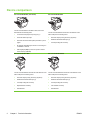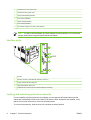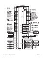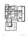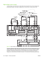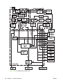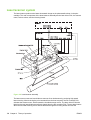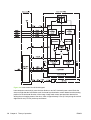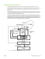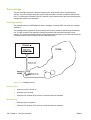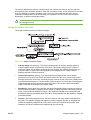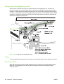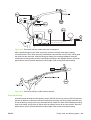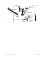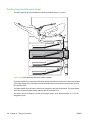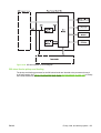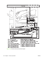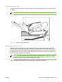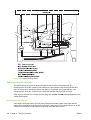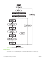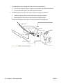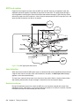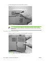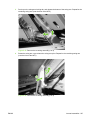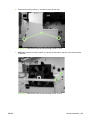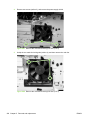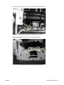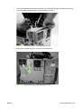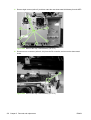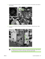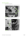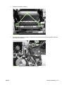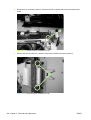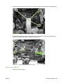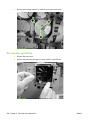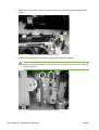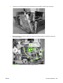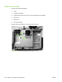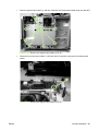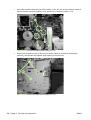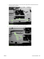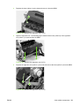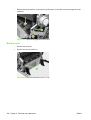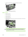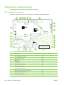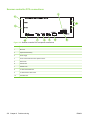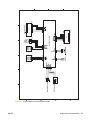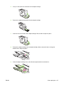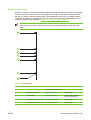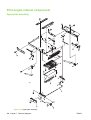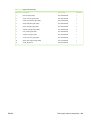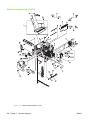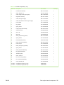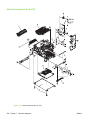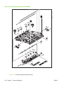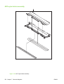
1
HP LaserJet M4345 MFP
Service Manual
HP LaserJet M4345 MFP
Service Manual
Copyright and License
Trademark Credits
© 2006 Copyright Hewlett-Packard
Development Company, L.P.
Java™ is a US trademark of Sun
Microsystems, Inc.
Reproduction, adaptation, or translation
without prior written permission is
prohibited, except as allowed under the
copyright laws.
Windows®, Windows® XP, and Windows
NT® are U.S. registered trademarks of
Microsoft Corporation.
The information contained in this document
is subject to change without notice.
The only warranties for HP products and
services are set forth in the express
warranty statements accompanying such
products and services. Nothing herein
should be construed as constituting an
additional warranty. HP shall not be liable
for technical or editorial errors or omissions
contained herein.
Part number CB425-90908
Edition 1, 10/2006
Linux is a U.S. registered trademark of
Linus Torvalds.
UNIX® is a registered trademark of The
Open Group.
Adobe® and PostScript® are trademarks
of Adobe Systems Incorporated.
PANTONE®* *Pantone, Inc.'s checkstandard trademark for color.
ENERGY STAR® and the ENERGY STAR
logo® are U.S. registered marks of the
United States Environmental Protection
Agency.
Table of contents
1 Product information
Device comparison ................................................................................................................................ 2
Features comparison .............................................................................................................................3
Walkaround ............................................................................................................................................ 6
Accessories and supplies ..................................................................................................... 7
Interface ports ....................................................................................................................... 8
Locking and unlocking optional accessories ........................................................................ 8
Media specifications ............................................................................................................................ 10
Select print media ............................................................................................................... 10
General media specifications .............................................................................................. 14
Media considerations .......................................................................................................... 14
Envelopes ........................................................................................................... 14
Envelopes with double side seams ................................................... 15
Envelopes with adhesive strips or flaps ............................................ 16
Envelope margins .............................................................................. 16
Envelope storage ............................................................................... 16
Labels .................................................................................................................16
Label construction ............................................................................. 16
Transparencies .................................................................................................. 16
Card stock and heavy media ............................................................................. 17
Card stock construction ..................................................................... 17
Card stock guidelines ........................................................................ 17
Letterhead and preprinted forms ........................................................................ 17
Select the correct fuser mode ............................................................................ 18
2 Installation
Site preparation ................................................................................................................................... 22
Operating environment ....................................................................................................... 22
Installation checklist ............................................................................................................................. 24
Optional output and input devices ....................................................................................................... 26
Connect to a computer or network ...................................................................................................... 27
USB configuration ............................................................................................................... 27
Network connection ............................................................................................................ 28
Fax connection .................................................................................................................... 28
Analog faxing ..................................................................................................... 28
Connecting the fax accessory to a phone line .................................. 28
Configuring and using the fax features ............................................. 29
Digital faxing ....................................................................................................... 29
Device software ................................................................................................................................... 30
ENWW
iii
Supported operating systems ............................................................................................. 30
Supported operating systems ............................................................................................. 31
Select the correct printer driver ........................................................................................... 32
Universal printer drivers ..................................................................................... 32
Driver Autoconfiguration ..................................................................................... 32
Update Now ........................................................................................................ 33
HP Driver Preconfiguration ................................................................................ 33
Priority for print settings ...................................................................................................... 33
Open the printer drivers ...................................................................................................... 34
Software for Macintosh computers ..................................................................................... 35
Remove software from Macintosh operating systems ....................................... 35
Utilities ................................................................................................................................. 36
HP Web Jetadmin .............................................................................................. 36
Embedded Web server ...................................................................................... 36
HP Easy Printer Care software .......................................................................... 37
Supported operating systems ............................................................ 37
Supported browsers .......................................................................... 37
Other components and utilities .......................................................................... 37
Network configuration .......................................................................................................................... 38
Configure TCP/IPv4 parameters ......................................................................................... 38
Change the IP address ...................................................................................... 38
Set the subnet mask .......................................................................................... 39
Set the default gateway ...................................................................................... 39
Configure TCP/IPv6 parameters ......................................................................................... 40
Disable network protocols (optional) .................................................................................. 40
Disable IPX/SPX ................................................................................................ 40
Disable AppleTalk .............................................................................................. 41
Disable DLC/LLC ............................................................................................... 41
HP Jetdirect EIO print servers ............................................................................................ 41
Security features .................................................................................................................................. 42
Securing the embedded Web server .................................................................................. 42
Foreign Interface Harness (FIH) ......................................................................................... 42
Requirements ..................................................................................................... 42
Using the FIH ..................................................................................................... 42
Secure Disk Erase .............................................................................................................. 43
Data affected ...................................................................................................... 44
Gaining access to Secure Disk Erase ................................................................ 44
Additional Information ........................................................................................ 44
Job-storage features ........................................................................................................... 44
HP DSS authentication ....................................................................................................... 44
Locking the control-panel menus ........................................................................................ 44
Locking the formatter cage ................................................................................................. 45
3 Manage and maintain the device
Control-panel menus ........................................................................................................................... 48
Use the control panel .......................................................................................................... 48
Control-panel layout ........................................................................................... 48
Home screen ...................................................................................................... 49
Buttons on the touchscreen ............................................................................... 50
Control-panel help system ................................................................................. 50
iv
ENWW
Navigate the Administration menu ...................................................................................... 50
Information menu ................................................................................................................ 51
Default Job Options menu .................................................................................................. 52
Default Options for Originals .............................................................................. 53
Default Copy Options ......................................................................................... 54
Default Fax Options ........................................................................................... 55
Default E-mail Options ....................................................................................... 56
Default Send to Folder Options .......................................................................... 57
Default Print Options .......................................................................................... 58
Time/Scheduling menu ....................................................................................................... 58
Management menu ............................................................................................................. 59
Initial Setup menu ............................................................................................................... 60
Networking and I/O ............................................................................................ 60
Fax Setup ........................................................................................................... 68
E-mail Setup ....................................................................................................... 71
Send Setup menu .............................................................................................. 71
Device Behavior menu ........................................................................................................ 71
Print Quality menu .............................................................................................................. 75
Troubleshooting menu ........................................................................................................ 77
Resets menu .......................................................................................................................79
Service menu ...................................................................................................................... 80
Use information pages ......................................................................................................................... 82
Configure e-mail alerts ........................................................................................................................ 84
HP Easy Printer Care software ........................................................................................................... 85
Open the HP Toolbox FX .................................................................................................... 85
HP Toolbox FX sections ..................................................................................................... 85
Use the embedded Web server ........................................................................................................... 87
Open the embedded Web server by using a network connection ...................................... 87
Embedded Web server sections ......................................................................................... 87
Use HP Web Jetadmin software ......................................................................................................... 90
Use the HP Printer Utility for Macintosh .............................................................................................. 91
Open the HP Printer Utility .................................................................................................. 91
HP Printer Utility features ................................................................................................... 91
Manage supplies .................................................................................................................................. 93
Supplies life expectancy ..................................................................................................... 93
Change the print cartridge .................................................................................................. 93
Manage the print cartridge .................................................................................................. 93
Print-cartridge storage ........................................................................................ 93
Use genuine HP print cartridges ........................................................................ 93
HP policy on non-HP print cartridges ................................................................. 94
Print-cartridge authentication ............................................................................. 94
HP fraud hotline and Web site ........................................................................... 94
Clean the device ..................................................................................................................................95
Clean the exterior ................................................................................................................ 95
Clean the scanner glass ..................................................................................................... 95
Clean the scanner lid backing ............................................................................................. 96
Clean the paper path .......................................................................................................... 96
Clean the document feeder ................................................................................................ 96
Clean the document feeder delivery system ...................................................... 97
Clean the document feeder-rollers ..................................................................... 98
ENWW
v
Set the real-time clock ....................................................................................................................... 100
Set the date and time ........................................................................................................ 100
Set the date format ........................................................................................... 100
Set the date ...................................................................................................... 100
Set the time format ........................................................................................... 100
Set the time ...................................................................................................... 100
Set the wake time ............................................................................................................. 101
Set the sleep delay ........................................................................................................... 101
Upgrading the firmware ..................................................................................................................... 102
Determining the current level of firmware ......................................................................... 102
Downloading the new firmware from the HP Web site ..................................................... 102
Transferring the new firmware to the MFP ....................................................................... 102
Using FTP to upgrade the firmware on a network connection ........................ 102
Using HP Web Jetadmin to upgrade the firmware .......................................... 104
Using MS-DOS commands to upgrade the firmware ...................................... 104
Upgrading the HP Jetdirect firmware ................................................................................ 105
Calibrate the scanner ........................................................................................................................ 106
Calibrate the control panel ................................................................................................................. 107
Disable Embedded Jetdirect I/O ........................................................................................................ 108
Select the MFP language .................................................................................................................. 109
4 Theory of operation
Basic operation ..................................................................................................................................112
Sequence of operation (printer) ........................................................................................ 112
Sequence of operation (scanner) ..................................................................................... 113
Formatter system ............................................................................................................................... 114
Sleep mode .......................................................................................................................114
Resolution Enhancement technology (REt) ...................................................................... 114
EconoMode .......................................................................................................................115
Input/output ....................................................................................................................... 115
CPU ................................................................................................................................... 115
Memory ............................................................................................................................. 115
Hard disk .......................................................................................................... 115
Random-access memory ................................................................................. 115
DIMM slot ......................................................................................................... 115
Firmware .......................................................................................................... 115
Nonvolatile memory ......................................................................................... 116
HP Memory Enhancement technology ............................................................ 116
PJL overview ..................................................................................................................... 116
PML ................................................................................................................................... 116
Control panel ..................................................................................................................... 116
Scanner interface .............................................................................................................. 116
Engine-control system ....................................................................................................................... 117
DC controller PCA ............................................................................................................. 117
Motors and fans ................................................................................................................ 119
Motor and fan functions .................................................................................... 119
Ambient-temperature detection ........................................................................ 120
Engine power supply circuit .............................................................................................. 120
Fuser control ..................................................................................................................... 121
Fuser over-temperature protection .................................................................. 122
vi
ENWW
High-voltage power supply ............................................................................................... 124
Low-voltage power supply ................................................................................................ 125
Overcurrent/overvoltage protection .................................................................................. 127
Toner detection ................................................................................................................. 127
Cartridge detection ............................................................................................................ 127
Laser/scanner system ....................................................................................................................... 128
Laser/scanner control ....................................................................................................... 129
Image-formation system .................................................................................................................... 131
Print cartridge .................................................................................................................... 132
Cartridge memory ............................................................................................ 132
Image-formation process .................................................................................................. 133
Pickup, feed, and delivery system ..................................................................................................... 135
Pickup-and-feed block ...................................................................................................... 138
Printing from tray 1 ........................................................................................... 139
Printing from tray 2 ........................................................................................... 140
Media-size detection ....................................................................... 141
Cassette media-size detection ....................................... 141
Media-length detection ................................................... 141
Media-width detection ..................................................... 141
Cassette pickup operation ............................................................... 141
Lifter-driver operation ...................................................................... 143
Multifeed prevention ........................................................................ 143
Distance-between-pages adjustment .............................................. 144
Media-skew prevention .................................................................................... 145
Feed-speed control .......................................................................................... 147
Fusing and reversing/delivery block ................................................................................. 148
Fusing ............................................................................................................... 148
Face-down delivery .......................................................................................... 148
Face-up delivery ............................................................................................... 149
Jam detection .................................................................................................................... 151
Pickup delay jam from tray 1 ............................................................................ 151
Pickup delay jam from tray 2 ............................................................................ 151
Pickup stationary jam ....................................................................................... 151
Fuser-delivery delay jam .................................................................................. 152
Fuser wrapping jam .......................................................................................... 152
Fuser-delivery stationary jam when feeding regular-size media ..................... 152
Fuser-delivery stationary jam when feeding custom-size media ..................... 152
Reversing delay jam (face-down delivery only) ............................................... 152
Reversing stationary jam (face-down delivery only) ........................................ 152
Delivery delay jam during face-down delivery ................................................. 153
Delivery delay jam during face-up delivery ...................................................... 153
Delivery stationary jam during face-down delivery .......................................... 153
Delivery stationary jam during face-up delivery ............................................... 153
Door-open jam ................................................................................................. 153
Residual-media jam ......................................................................................... 153
Printing from the 500-sheet feeder ................................................................................... 154
500-sheet feeder pickup and feeding .............................................................. 155
Duplex-printing unit ........................................................................................................... 157
Reversing/duplexing pickup ............................................................................. 157
Duplex-printing jam detection .......................................................................... 158
ENWW
vii
Duplex-unit-pickup delay jam .......................................................... 158
Duplex-unit stationary jam ............................................................... 159
Duplex-unit delay jam ...................................................................... 159
3-bin mailbox system ......................................................................................................................... 160
Stacker mode ....................................................................................................................162
Mailbox mode .................................................................................................................... 162
Function-separator mode .................................................................................................. 162
Jam detection .................................................................................................................... 162
Feed-delay jam ................................................................................................ 163
Feed-stationary jam ......................................................................................... 163
Residual-media jam ......................................................................................... 163
Power-on sequence .......................................................................................................... 163
MBM driver ........................................................................................................................ 164
MBM switches and sensors .............................................................................................. 167
MBM PCBs ....................................................................................................................... 168
MBM list of signals ............................................................................................................ 169
Stapler/stacker system ...................................................................................................................... 171
Power-on sequence .......................................................................................................... 171
Staple mode ......................................................................................................................172
Jogger operation ............................................................................................................... 178
Jogger home-position detection ....................................................................................... 182
Stacker mode ....................................................................................................................184
Jam detection .................................................................................................................... 184
Stapler unit ........................................................................................................................185
Staple home position detection ........................................................................ 186
Self-priming detection ...................................................................................... 186
Staple level detection ....................................................................................... 186
Stapler/stacker switches and sensors .............................................................................. 187
Stapler/stacker motors, solenoid, and fan ........................................................................ 189
Stapler/stacker PCBs ........................................................................................................ 190
Stapler/stacker driver PCB ............................................................................................... 193
Stapler/stacker driver list of signals .................................................................................. 195
Scanner system .................................................................................................................................198
Electrical system ............................................................................................................... 198
Motors and fans ................................................................................................................ 200
Optical assembly ............................................................................................................... 200
ADF feed system .............................................................................................................. 202
Jam detection .................................................................................................................... 202
Residual-media jam ......................................................................................... 202
ADF pickup jam ................................................................................................ 203
ADF jam ........................................................................................................... 203
Registration sensor jam ................................................................... 203
Read sensor jam ............................................................................. 203
Exit sensor jam ................................................................................ 203
ADF cover open jam ........................................................................................ 203
ADF open jam .................................................................................................. 203
Locations of major components ........................................................................................................ 204
Sensors and switches ....................................................................................................... 204
Cassette sensors ............................................................................................. 204
Sensors in the print-cartridge area ................................................................... 205
viii
ENWW
Sensors on the reversing unit (top side) .......................................................... 205
Sensors in the interior of the MFP ................................................................... 206
Output-bin detection switch, SW103 ................................................................ 207
Tray 1 paper-present sensor, PS105 ............................................................... 207
Top-cover switch, SW101 ................................................................................ 208
Tray 2 jam-access-cover switch, SW105 ......................................................... 208
Motors, fans, solenoids, and clutch .................................................................................. 208
Front-side fans ................................................................................................. 209
Rear-side fans .................................................................................................. 210
Rear-side motors (1 of 2) ................................................................................. 210
Rear-side motors (2 of 2) ................................................................................. 211
Rear-side solenoid ........................................................................................... 212
Reversing-unit motors and solenoids .............................................................. 213
Right, rear corner components (1 of 2) ............................................................ 214
Right, rear corner components (2 of 2) ............................................................ 215
Scanner and ADF components ......................................................................................... 215
ADF output-bin-full sensor ............................................................................... 215
ADF pickup assembly sensors ......................................................................... 216
ADF motors, solenoid, and sensors ................................................................. 216
5 Removal and replacement
Service approach ............................................................................................................................... 220
Removal and replacement strategy ................................................................................................... 221
Required tools ................................................................................................................... 221
Before performing service ................................................................................................. 221
After completing service ................................................................................................... 222
Screws that are used in the MFP ..................................................................................... 222
User-replaceable parts ...................................................................................................................... 224
Print cartridge .................................................................................................................... 224
Control-panel overlays ...................................................................................................... 224
Control panel ..................................................................................................................... 225
Transfer roller .................................................................................................................... 226
ADF input tray ................................................................................................................... 227
ADF pickup and feed rollers ............................................................................................. 228
ADF separation pad .......................................................................................................... 229
ADF delivery guide (clear mylar sheet) ............................................................................ 231
Output-bin assembly ......................................................................................................... 233
Duplex-printing unit ........................................................................................................... 234
Fuser-entrance guide ........................................................................................................ 235
Fuser .................................................................................................................................235
Tray 2, 3, 4, or 5 pickup and feed rollers .......................................................................... 236
Tray 1 pickup roller ........................................................................................................... 237
Scanner filter cover and scanner filter .............................................................................. 238
ADF-hinge flap .................................................................................................................. 239
Formatter cover and formatter .......................................................................................... 240
Hard drive ......................................................................................................................... 242
DIMM ................................................................................................................................. 243
Fax accessory ...................................................................................................................244
Covers, doors, and external panels ................................................................................................... 246
Top-cover flatbed flange ................................................................................................... 246
ENWW
ix
Front cover ........................................................................................................................247
Back cover ........................................................................................................................ 251
Internal assemblies ............................................................................................................................ 253
Reversing-separation-guide assembly ............................................................................. 253
Reversing assembly .......................................................................................................... 254
Main fan (FN101) and reversing-unit fan (FN103) ........................................................... 258
Thermistor (TH3) ............................................................................................................... 263
Tray 2 jam-access-cover switch (SW105) ........................................................................ 265
Tray 1 assembly ................................................................................................................ 267
Front-cover support ........................................................................................................... 269
Tray 1 feed-assembly ....................................................................................................... 271
Feed-roller assembly ........................................................................................................ 278
DC controller ..................................................................................................................... 280
Main motor (M101) ............................................................................................................ 283
DC controller fan (FN104) ................................................................................................. 284
Print-cartridge fan (FN102) ............................................................................................... 285
Print-cartridge motor (M102) ............................................................................................. 287
Top-cover switch (SW101) ............................................................................................... 290
Registration assembly ...................................................................................................... 292
Paper-pickup-drive assembly ........................................................................................... 295
Lifter-drive assembly ......................................................................................................... 298
Power-factor-correction (PFC) power supply ................................................................... 301
Engine power supply ........................................................................................................ 306
Paper-feed assembly ........................................................................................................ 311
Tray 2 detection switch ..................................................................................................... 312
Paper-size-detection switch (SW102) .............................................................................. 313
Tray 2 paper-present sensor (PS101) .............................................................................. 314
Laser/scanner ................................................................................................................... 315
Output-bin-full sensor ....................................................................................................... 316
ADF and scanner components .......................................................................................................... 319
ADF assembly ................................................................................................................... 319
Scanner assembly ............................................................................................................ 321
Scanner-controller PCA .................................................................................................... 326
ADF components ...............................................................................................................................327
ADF output-bin extension ................................................................................................. 327
ADF white mylar-backing .................................................................................................. 328
ADF front cover ................................................................................................................. 330
ADF rear cover .................................................................................................................. 331
ADF left-side cover ........................................................................................................... 332
ADF jam-access cover and latch ...................................................................................... 334
ADF leading-edge and paper-present sensors ................................................................ 335
ADF hinges ....................................................................................................................... 337
500-sheet feeder components ........................................................................................................... 339
500-sheet-feeder pickup and feed rollers ......................................................................... 339
Stapler/stacker components .............................................................................................................. 340
Delivery tray ...................................................................................................................... 340
Front cover ........................................................................................................................340
Rear cover ........................................................................................................................ 340
Left cover .......................................................................................................................... 341
Top cover .......................................................................................................................... 341
x
ENWW
Bottom cover .....................................................................................................................342
Stapler unit ........................................................................................................................343
Jogger unit ........................................................................................................................ 344
Stapler/stacker driver PCB ............................................................................................... 348
3-bin mailbox components ................................................................................................................. 350
Rear cover ........................................................................................................................ 350
Front cover ........................................................................................................................350
Delivery tray ...................................................................................................................... 350
Left cover .......................................................................................................................... 351
Upper cover ...................................................................................................................... 351
Right-door unit .................................................................................................................. 352
Bottom cover .....................................................................................................................354
MBM driver PCB ............................................................................................................... 355
6 Problem solving
Problem-solving checklist .................................................................................................................. 359
Factors that affect performance ........................................................................................ 359
Problem-solving flowchart ................................................................................................................. 360
Power-on checks ............................................................................................................................... 364
Power-on troubleshooting overview ................................................................................. 364
Formatter lights .................................................................................................................................. 366
HP Jetdirect Inside LEDs .................................................................................................. 366
Heartbeat LED .................................................................................................................. 366
Fax LED ............................................................................................................................ 367
Diagrams for troubleshooting ............................................................................................................ 368
DC controller connections ................................................................................................. 368
Scanner-controller PCA connections ................................................................................ 370
General timing chart ......................................................................................................... 371
General circuit diagrams ................................................................................................... 373
Solve general device problems ......................................................................................................... 379
Control-panel message types ............................................................................................................ 382
Control-panel messages .................................................................................................................... 383
Common causes of jams ................................................................................................................... 399
Clear jams .......................................................................................................................................... 400
Clear jams from the top-cover and print-cartridge areas .................................................. 401
Clear jams from the optional envelope-feeder area ......................................................... 403
Clear jams from the tray 1 area ........................................................................................ 405
Clear jams from the tray 2, 3, 4, or 5 areas ...................................................................... 406
Clear jams from the optional duplexer .............................................................................. 408
Clear jams from the output areas ..................................................................................... 409
Clear jams from the fuser ................................................................................................. 410
Clear jams from the document feeder .............................................................................. 413
Solve repeated jams ......................................................................................................... 414
Paper-path test ................................................................................................................. 415
Clear staple jams ...............................................................................................................................416
Solve print-quality problems .............................................................................................................. 418
Print-quality problems associated with media .................................................................. 418
Print-quality problems associated with the environment .................................................. 418
Print-quality problems associated with jams ..................................................................... 418
Overhead transparency defects ........................................................................................ 418
ENWW
xi
Image defect examples ..................................................................................................... 419
Light print (partial page) ................................................................................... 419
Light print (entire page) .................................................................................... 419
Specs ............................................................................................................... 420
Dropouts ........................................................................................................... 420
Lines .................................................................................................................421
Gray background .............................................................................................. 421
Toner smear ..................................................................................................... 422
Loose toner ...................................................................................................... 423
Repeating defects ............................................................................................ 423
Repeating image .............................................................................................. 424
Misformed characters ....................................................................................... 424
Page skew ........................................................................................................ 425
Curl or wave ..................................................................................................... 425
Wrinkles or creases .......................................................................................... 426
Vertical white lines ........................................................................................... 427
Tire tracks ......................................................................................................... 427
White spots on black ........................................................................................ 428
Scattered lines ................................................................................................. 428
Blurred print ...................................................................................................... 429
Random image repetition ................................................................................. 429
Repetitive defect ruler ...................................................................................... 431
Solve network printing problems ....................................................................................................... 433
Solve copy problems ......................................................................................................................... 434
Prevent copy problems ..................................................................................................... 434
Image problems ................................................................................................................ 434
Media-handling problems ................................................................................................. 435
Performance problems ..................................................................................................... 437
Solve fax problems ............................................................................................................................ 438
Solve sending problems ................................................................................................... 438
Solve receiving problems .................................................................................................. 439
Solve e-mail problems ....................................................................................................................... 441
Validate the SMTP gateway address ............................................................................... 441
Validate the LDAP gateway address ................................................................................ 441
Solve network connectivity problems ................................................................................................ 442
Troubleshooting network printing problems ...................................................................... 442
Loopback test .................................................................................................................... 442
Ping test ............................................................................................................................ 443
Solve stapler/stacker problems ......................................................................................................... 444
Solve 3-bin mailbox problems ........................................................................................................... 451
Functional checks ..............................................................................................................................454
Early boot diagnostic test .................................................................................................. 454
Engine test ........................................................................................................................ 454
Formatter test .................................................................................................................... 455
Half self-test ...................................................................................................................... 455
Drum-rotation test ............................................................................................................. 456
MFP resets ........................................................................................................................................ 457
Cold reset .......................................................................................................................... 457
NVRAM initialization ......................................................................................................... 457
Hard-disk initialization ....................................................................................................... 458
xii
ENWW
Individual component diagnostics ..................................................................................................... 459
Paper-path-sensor test ..................................................................................................... 459
Manual sensor test ............................................................................................................ 459
Scanner tests .................................................................................................................... 460
Component test ................................................................................................................. 461
Service ID .......................................................................................................................................... 462
Restoring the Service ID ................................................................................................... 462
Converting the service ID to an actual date ...................................................................... 462
Troubleshooting the embedded HP Jetdirect print server ................................................................. 463
Firmware-stack trace ......................................................................................................................... 464
Solve common Windows problems .................................................................................................. 465
Solve common Macintosh problems ................................................................................................. 466
Solve Linux problems ........................................................................................................................ 469
Solve PostScript problems ................................................................................................................ 470
General problems ............................................................................................................. 470
7 Parts and diagrams
Order parts, accessories, and supplies ............................................................................................. 472
Order directly from HP ...................................................................................................... 472
Order through service or support providers ...................................................................... 472
Order directly through the embedded Web server ........................................................... 472
How to use the parts lists and diagrams ........................................................................................... 472
Screws that are used in the MFP ...................................................................................................... 473
Customer-replaceable parts and accessories ................................................................................... 474
Accessories ....................................................................................................................... 474
Customer-replaceable components (print engine) ........................................................... 476
Customer-replaceable components (ADF and scanner) .................................................. 478
Cables and interfaces ....................................................................................................... 480
Control panel and control-panel overlays ......................................................................... 483
Memory ............................................................................................................................. 485
Print cartridge and maintenance kits ................................................................................ 487
Documentation, software, and training material ................................................................................ 490
Assembly locations ............................................................................................................................492
External components ......................................................................................................................... 496
Print-engine internal components ...................................................................................................... 498
Upper-plate assembly ....................................................................................................... 498
Internal components (1 of 5) ............................................................................................. 500
Internal components (2 of 5) ............................................................................................. 502
Internal components (3 of 5) ............................................................................................. 504
Internal components (4 of 5) ............................................................................................. 506
Internal components (5 of 5) ............................................................................................. 508
Electrical/forward assembly .............................................................................................. 510
Main drive assembly ......................................................................................................... 512
Paper-pickup-drive assembly ........................................................................................... 514
Lifter-drive assembly ......................................................................................................... 516
Cassette ............................................................................................................................518
Paper-feed roller assembly ............................................................................................... 520
Registration assembly ...................................................................................................... 522
Multipurpose assembly ..................................................................................................... 524
Reverse assembly ............................................................................................................ 526
ENWW
xiii
Reverse-separation-guide assembly ................................................................................ 528
Delivery assembly ............................................................................................................. 530
Fuser .................................................................................................................................532
ADF components ...............................................................................................................................534
ADF assembly ................................................................................................................... 534
ADF internal components (1 of 3) ..................................................................................... 536
ADF internal components (2 of 3) ..................................................................................... 538
ADF internal components (3 of 3) ..................................................................................... 540
ADF input tray ................................................................................................................... 542
ADF separation pad .......................................................................................................... 544
ADF separation-pad case ................................................................................................. 546
ADF pickup-roller assembly .............................................................................................. 548
ADF pickup-roller cover .................................................................................................... 550
ADF mylar-holder assembly ............................................................................................. 552
ADF mylar replacement kit ............................................................................................... 554
Scanner components ......................................................................................................................... 556
Scanner-base components ............................................................................................... 556
Scanner flatbed-unit assembly ......................................................................................... 558
Scanner covers ................................................................................................................. 560
Cassette ............................................................................................................................................. 562
Optional devices ................................................................................................................................ 564
Duplex-printing accessory ................................................................................................ 564
Stapler/stacker .................................................................................................................. 566
3-bin mailbox ..................................................................................................................... 568
Alphabetical parts list ......................................................................................................................... 570
Numerical parts list ............................................................................................................................ 586
Appendix A Specifications
Physical specifications ....................................................................................................................... 604
Electrical specifications ..................................................................................................................... 604
Acoustic specifications ...................................................................................................................... 605
Operating environment ...................................................................................................................... 606
Appendix B Product warranty statements
Hewlett-Packard limited warranty statement ..................................................................................... 607
Customer Self Repair Warranty Service ........................................................................................... 608
HP Customer Care ............................................................................................................................ 609
Online Services ................................................................................................................. 609
Telephone support ............................................................................................................ 609
Software utilities, drivers, and electronic information ....................................................... 609
Fax accessory support ...................................................................................................... 609
HP direct ordering for accessories or supplies ................................................................. 609
HP service information ...................................................................................................... 609
HP service agreements .................................................................................................... 609
HP Toolbox FX .................................................................................................................. 610
HP support and information for Macintosh computers ..................................................... 610
HP maintenance agreements ............................................................................................................ 611
On-site service agreements .............................................................................................. 611
Next-day on-site service ................................................................................... 611
Weekly (volume) on-site service ...................................................................... 611
xiv
ENWW
Repacking the device ....................................................................................................... 611
Extended warranty ............................................................................................................ 612
Appendix C Regulatory information
FCC regulations ................................................................................................................................. 614
Environmental product stewardship program .................................................................................... 615
Protecting the environment ............................................................................................... 615
Ozone production .............................................................................................................. 615
Power consumption .......................................................................................................... 615
Toner consumption ........................................................................................................... 615
Paper use .......................................................................................................................... 615
Plastics .............................................................................................................................. 615
HP LaserJet print supplies ................................................................................................ 616
HP print supplies returns and recycling program information .......................................... 616
Paper ................................................................................................................................. 616
Material restrictions ........................................................................................................... 617
Disposal of waste equipment by users in private households in the European Union .... 617
Material Safety Data Sheet (MSDS) ................................................................................. 618
For more information ........................................................................................................ 618
Telecom statement ............................................................................................................................ 619
Declaration of conformity ................................................................................................................... 620
Safety statements ..............................................................................................................................621
Laser safety ...................................................................................................................... 621
Canadian DOC regulations ............................................................................................... 621
VCCI statement (Japan) ................................................................................................... 621
Power cord statement (Japan) .......................................................................................... 621
EMI statement (Korea) ...................................................................................................... 621
Laser statement for Finland .............................................................................................. 621
Index ..................................................................................................................................................................623
ENWW
xv
xvi
ENWW
1
Product information
The HP LaserJet M4345 is designed to be shared by a workgroup. Use the MFP to copy and print
black-and-white documents or to digitally send black-and-white documents. The MFP is a standalone
copier that does not require connection to a computer. With the optional HP LaserJet Analog Fax
Accessory 300 User Guide (included with some models), the MFP can also send and receive faxes.
If you have not done so, see the HP LaserJet M4345 Getting Started Guide for setup instructions.
This chapter introduces the following topics:
ENWW
●
Device comparison
●
Features comparison
●
Walkaround
●
Media specifications
1
Device comparison
HP LaserJet M4345 MFP (base model)
The HP LaserJet M4345 is the base model, and comes
standard with the following items:
2
●
A 100-sheet multipurpose input tray (tray 1)
●
Three 500-sheet input trays
●
Automatic document feeder (ADF) that holds up to 50
pages
●
HP Jetdirect embedded print server for connecting to a
10/100Base-T network
●
256 megabytes (MB) synchronous dynamic random
access memory (SDRAM)
HP LaserJet M4345x MFP
The HP LaserJet M4345x includes all of the features of the
base model plus the following items:
●
Automatic duplex printing accessory (duplexer)
●
Additional 500-sheet feeder (tray 3)
●
33.6 kbps analog-fax accessory
HP LaserJet M4345xs MFP
HP LaserJet M4345xm MFP
The HP LaserJet M4345xs includes all of the features of the
base model plus the following items:
The HP LaserJet M4345xm includes all of the features of the
base model plus the following items:
●
Automatic duplex printing accessory (duplexer)
●
Automatic duplex printing accessory (duplexer)
●
Additional 500-sheet feeder (tray 3)
●
Additional 500-sheet feeder (tray 3)
●
33.6 kbps analog-fax accessory
●
33.6 kbps analog-fax accessory
●
Stapler/stacker accessory
●
3-bin mailbox accessory
●
Cabinet/stand
●
Cabinet/stand
Chapter 1 Product information
ENWW
Features comparison
Feature
HP LaserJet M4345
Functions
●
Two-sided copying (duplexing)
●
Image modification
●
Color digital sending
●
Document finishing
●
45 pages per minute (ppm) when scanning and printing
on letter-size paper; 43(ppm) when copying and
printing on A4-size paper
●
25% to 400% scalability when using the scanner glass
●
25% to 200% scalability when using the automatic
document feeder (ADF)
●
Less than 10 seconds to print the first page
●
Transmit Once, Raster Image Processing (RIP) ONCE
technology
●
Duty cycle of up to 200,000 pages per month
●
1200 dots per inch (dpi) with Resolution Enhancement
technology (REt)
●
FastRes1200 provides 1200 dpi quality at full speed
●
Up to 220 levels of gray
●
256 megabytes (MB) of random-access memory
(RAM), expandable to 512 MB by using an industry
standard 100-pin double data rate memory module
(DDR SDRAM DIMM)
●
Memory Enhancement technology (MEt) that
automatically compresses data to use RAM more
efficiently
●
Graphical touchscreen control panel
●
An embedded Web server to gain access to support
and order supplies (for network-connected products)
●
HP Easy Printer Care software (a Web-based status
and troubleshooting tool).
●
HP PCL 6
●
HP PCL5
●
Printer Management Language
●
PDF
●
XHTML
●
80 scalable TrueType typefaces
●
HP PostScript 3 emulation
Speed and throughput
Resolution
Memory
User interface
Language and fonts
ENWW
Features comparison
3
Copying and sending
●
Modes for text, graphics, and mixed text and graphics
formats
●
A job-interrupt feature (at copy boundaries)
●
Xenon lamp for instant-on copying
●
Multiple pages per sheet
●
Operator attendance animations (for example, jam
recovery)
●
E-mail compatibility
●
A sleep feature that saves energy
●
Automatic duplex (two-sided) scanning
NOTE An automatic duplex printing accessory is
required for two-sided copying.
NOTE To use e-mail functionality, the device must
be connected to an IP-based server that has simple
mail transfer protocol (SMTP). This server can be
on the local area network or at an outside Internet
service provider (ISP). HP recommends that the
device be located on the same local area network
(LAN) as the SMTP server. If you are using an ISP,
you must connect to the ISP by using a digital
subscriber line (DSL) connection. If you obtain email services from an ISP, ask the ISP to provide
the correct SMTP address.
Dial-up connections are not supported. If you do not
have an SMTP server on your network, you can
purchase third-party software that allows you to
create an SMTP server.
Print cartridge
Paper Input
4
Chapter 1 Product information
●
Prints up to 18,000 pages at 5% coverage.
●
No-shake cartridge design
●
Authentic HP print cartridge detection
●
Tray 1 (multipurpose tray): A multipurpose tray for
paper, transparencies, labels, and envelopes. Holds up
to 100 sheets of paper or 10 envelopes.
●
Tray 2 and optional trays 3, 4, and 5: 500-sheet
trays. These trays automatically detect standard paper
sizes up to Legal and accommodate printing on customsize paper.
●
Automatic document feeder (ADF): Holds up to 50
sheets of paper.
●
Duplex printing and copying: With the optional
duplexing accessory, provides two-sided printing and
copying (printing on both sides of the paper).
●
ADF duplex scanning: The ADF has an automatic
duplex feature for scanning two-sided documents.
●
Optional envelope feeder: Holds up to 75 envelopes.
ENWW
Paper output
Connectivity
ENWW
●
Standard output bin: The standard output bin is
located on the left side of the device. This bin can hold
up to 500 sheets of paper.
●
ADF output bin: The ADF output bin is underneath the
ADF input tray. The bin holds up to 50 sheets, and the
device automatically stops when this bin is full.
●
Optional stapler/stacker: The stapler/stacker staples
up to 30 sheets and stacks up to 500 sheets.
●
Optional 3-bin mailbox: One bin stacks up to 500
sheets, and two bins stack up to 100 sheets each for a
total capacity of 700 sheets.
●
A Foreign interface harness (FIH) connection (AUX) for
connecting other devices
●
Local area network (LAN) connector (RJ-45) for the
embedded HP Jetdirect print server
●
Optional analog-fax card
●
Optional HP Digital Sending Software (DSS)
●
High-speed USB 2.0
●
Jetlink for paper handling solutions
●
Optional HP Jetdirect enhanced input/output (EIO) print
server cards:
●
LocalTalk
●
Fast Ethernet 10/100TX
●
Ethernet 802.11b wireless
●
Bluetooth wireless printer adapter
●
Infrared adapter
Environmental features
●
The Sleep setting saves energy (meets ENERGY
STAR guidelines).
Security features
●
Foreign interface harness (FIH)
●
Secure Disk Erase
●
Security lock
●
Job retention
●
DSS authentication
Features comparison
5
Walkaround
6
1
Document-feeder assembly
2
Document-feeder top cover
3
Document-feeder input tray
4
Top cover (provides access to the print cartridge)
5
Top-cover lever
6
Tray 1 (multipurpose tray)
7
Jam-access lever
8
Tray-number indicator
9
Paper-level indicator
10
Control-panel keypad
11
Control-panel display
12
Control-panel status lights
13
Scanner lock
Chapter 1 Product information
ENWW
14
Output bin
15
Optional duplexer
16
On/off switch
17
Power connection
18
Interface ports
19
Formatter cover (provides access to the memory DIMM slot, hard disk, and analog-fax accessory)
Accessories and supplies
ENWW
1
500-sheet feeder (Q5968A)
2
Duplexer (Q5969A)
3
Envelope feeder (Q2438B)
4
Stapler/stacker (Q5691A)
5
Memory DIMM
Walkaround
7
6
HP Jetdirect print server (EIO card)
7
Hard-disk accessory (EIO card)
8
Storage cabinet/stand (Q5970A)
9
3-bin mailbox (Q5692A)
10
Staple cartridge (C8091A)
11
Print cartridge (Q5945A)
12
HP LaserJet Analog Fax Accessory 300 (Q3701A)
NOTE The device accommodates up to three optional 500-sheet feeders. HP recommends
using a cabinet when using the optional 500-sheet feeders.
Interface ports
1
EIO slot
2
Network connection (embedded HP Jetdirect print server)
3
Foreign interface harness (FIH) port
4
High-speed USB 2.0 device port
5
Telephone-line connection (for the optional analog-fax accessory)
Locking and unlocking optional accessories
For more stability to prevent the device from tipping over, the optional 500-sheet feeders and the
cabinet are automatically locked to the bottom of the device. When accessories are installed, verify
that the lock on each accessory is in the rear (locked) position.
To unlock the accessories, slide the lever to the forward (unlocked) position.
8
Chapter 1 Product information
ENWW
ENWW
Walkaround
9
Media specifications
Select print media
Table 1-1 Supported types of media
Type of media
Tray 1
Trays 2, 3,
4, and 5
Optional duplexer
Optional
envelope feeder
3-bin mailbox or
stacker part of
stapler/stacker
Stapler part of
stapler/stacker
Plain
X
X
X
X
X
X
Preprinted
X
X
X
X
X
X
Letterhead
X
X
X
X
X
X
Transparency
X
X
Prepunched
X
X
Labels
X
X
Bond
X
Recycled
X
X
X
X
X
X
X
X
X
X
X
X
X
X
X
X
X
Color
X
X
X
X
X
X
Cardstock
X
X
X12
Rough
X
X
X
Envelope
X
X
X1
1
2
10
X
X
X
X
Face-up delivery only.
If a 3-bin mailbox is installed, select the bottom bin when printing on cardstock. Media weights that
are 200g/m2 or greater are supported only in the bottom bin.
Chapter 1 Product information
ENWW
Table 1-2 Tray 1 supported sizes and weights
Size
Dimensions1
Weight
Capacity2
Letter
216 x 279 mm (8.5 x 11 inches)
60 to 200g/m2 (16 to 53 lb)
A4
210 x 297 mm (8.3 x 11.7 inches)
100 sheets of 75g/m2 (20 lb)
paper
Legal
216 x 356 mm (8.5 x 14 inches)
Executive
184 x 267 mm (7.3 x 10.5 inches)
Statement
140 x 216 mm (5.5 x 8.5 inches)
8.5 x 13
216 x 330 mm (8.5 x 13 inches)
A5
148 x 210 mm (5.8 x 8.3 inches)
B5 (JIS)
182 x 257 mm (7.2 x 10.1 inches)
Executive (JIS)
216 x 330 mm (8.5 x 13 inches)
D Postcard (JIS)
148 x 200 mm (5.8 x 7.9 inches)
16K
197 x 273 mm (7.75 x 10.75 inches)
Custom
Minimum: 76 x 127 mm (3 x 5
inches)
75 to 105g/m2 (20 to 28 lb)
10 envelopes
Maximum: 216 x 356 mm (8.5 x 14
inches)
Envelope Commercial #10
105 x 241 mm (4.1 x 9.5 inches)
Envelope DL ISO
110 x 220 mm (4.3 x 8.7 inches)
Envelope C5 ISO
162 x 229 mm (6.4 x 9.0 inches)
Envelope B5 ISO
176 x 250 mm (6.9 x 9.8 inches)
Envelope Monarch #7-3/4
98 x 191 mm (3.9 x 7.5 inches)
1
2
ENWW
The MFP supports a wide range of sizes. Check the MFP software for supported sizes.
Capacity can vary depending on paper weight and thickness, as well as environmental conditions.
Media specifications
11
Table 1-3 Trays 2, 3, 4, and 5 supported sizes and weights
Size
Dimensions1
Weight
Capacity2
Letter
216 x 279 mm (8.5 x 11 inches)
60 to 120g/m2 (16 to 32 lb)
A4
210 x 297 mm (8.3 x 11.7 inches)
500 sheets of 75g/m2 (20 lb)
paper
Executive
184 x 267 mm (7.3 x 10.5 inches)
Legal
216 x 356 mm (8.5 x 14 inches)
B5 (JIS)
182 x 257 mm (7.2 x 10.1 inches)
A5
148 x 210 mm (5.8 x 8.3 inches)
8.5 x 13
216 x 330 mm (8.5 x 13 inches)
Executive (JIS)
216 x 330 mm (8.5 x 13 inches)
16K
197 x 273 mm (7.75 x 10.75 inches)
Custom
Minimum: 148 x 210 mm (5.8 x 8.3
inches)
Maximum: 216 x 356 mm (8.5 x 14
inches)
1
2
The MFP supports a wide range of sizes. Check the MFP software for supported sizes.
Capacity can vary depending on paper weight and thickness, as well as environmental conditions.
Table 1-4 Optional duplexer supported sizes and weights
Size
Dimensions
Weight
Letter
216 x 279 mm (8.5 x 11 inches)
60 to 120g/m2 (16 to 32 lb)
A4
210 x 297 mm (8.3 x 11.7 inches)
Executive
184 x 267 mm (7.3 x 10.5 inches)
Legal
216 x 356 mm (8.5 x 14 inches)
B5 (JIS)
182 x 257 mm (7.2 x 10.1 inches)
A5
148 x 210 mm (5.8 x 8.3 inches)
8.5 x 13
216 x 330 mm (8.5 x 13 inches)
Executive (JIS)
216 x 330 mm (8.5 x 13 inches)
16K
197 x 273 mm (7.75 x 10.75 inches)
12
Chapter 1 Product information
ENWW
Table 1-5 Optional envelope feeder supported sizes and weights
Size
Dimensions
Weight
Capacity
Monarch #7-3/4
98 x 191 mm (3.9 x 7.5 inches)
75 to 105g/m2 (20 to 28 lb)
75 envelopes
Commercial #10
105 x 241 mm (4.1 x 9.5 inches)
DL ISO
110 x 220 mm (4.3 x 8.7 inches)
C5 ISO
162 x 229 mm (6.4 x 9.0 inches)
B5 ISO
176 x 250 mm (6.9 x 9.8 inches)
Table 1-6 Optional 3-bin mailbox or stacker part of the stapler/stacker supported sizes and weights
Size
Dimensions1
Letter
216 x 279 mm (8.5 x 11 inches)
A4
210 x 297 mm (8.3 x 11.7 inches)
Executive
184 x 267 mm (7.3 x 10.5 inches)
Legal
216 x 356 mm (8.5 x 14 inches)
B5 (JIS)
182 x 257 mm (7.2 x 10.1 inches)
A5
148 x 210 mm (5.8 x 8.3 inches)
Statement
140 x 216 mm (5.5 x 8.5 inches)
8.5 x 13
216 x 330 mm (8.5 x 13 inches)
Executive(JIS)
216 x 330 mm (8.5 x 13 inches)
DPostcard (JIS)
148 x 200 mm (5.8 x 7.9 inches)
16K
197 x 273 mm (7.75 x 10.75 inches)
Envelope #10 3
105 x 241 mm (4.1 x 9.5 inches)
Envelope Monarch #7-3/4 3
98 x 191 mm (3.9 x 7.5 inches)
Envelope C5 ISO 3
162 x 229 mm (6.4 x 9.0 inches)
Envelope DL ISO 3
110 x 220 mm (4.3 x 8.7 inches)
Envelope B5 ISO 3
176 x 250 mm (6.7 x 9.8 mm)
Custom
Minimum: 76 x 127 mm (3 x 5 inches)
Weight
Capacity2
For the stacker on the stapler/
stacker or the lower bin on the
3-bin mailbox: 500 sheets of
75g/m2 (20 lb) paper
For the top two bins on the 3bin mailbox: each can hold 100
sheets of 75g/m2 (20 lb) paper.
Maximum: 216 x 356 mm (8.5 x 14
inches)
1
2
3
ENWW
The MFP supports a wide range of sizes. Check the MFP software for supported sizes.
Capacity can vary depending on paper weight and thickness, as well as environmental conditions.
Face-up delivery only.
Media specifications
13
Table 1-7 Stapler part of the optional stapler/stacker supported sizes and weights
Size
Dimensions
Weight
Capacity
Letter
216 x 279 mm (8.5 x 11 inches)
A4
210 x 297 mm (8.3 x 11.7 inches)
For plain media: 60 to 120g/
m2 (16 to 32 lb)
For plain media: 30 sheets of 75g/
m2 (20 lb) paper
Legal
216 x 356 mm (8.5 x 14 inches)
For thick media: 128 to 199g/
m2 (34 to 53 lb)
For glossy media: 20 sheets
8.5 x 13
216 x 330 mm (8.5 x 13 inches)
Executive(JIS)
216 x 330 mm (8.5 x 13 inches)
For thick media: the stack height
must not exceed 7 mm (0.27 inch)
Table 1-8 ADF supported sizes and weights
Size
Dimensions
Weight
Capacity
Letter
216 x 279 mm (8.5 x 11 inches)
60 to 120g/m2 (16 to 32 lb) 50 sheets of 75g/m2 (20 lb) paper
A4
210 x 297 mm (8.3 x 11.7 inches)
A5
148 x 210 mm (5.8 x 8.3 inches)
Legal
216 x 356 mm (8.5 x 14 inches)
General media specifications
For complete paper specifications for all HP LaserJet devices, see the HP LaserJet Printer Family
Print Media Guide (available at http://www.hp.com/support/ljpaperguide) .
Category
Specifications
Acid content
5.5 pH to 8.0 pH
Caliper
0.094 to 0.18 mm (3.0 to 7.0 mils)
Curl in ream
Flat within 5 mm (0.02 in)
Cut edge conditions
Cut with sharp blades with no visible fray.
Fusing compatibility
Must not scorch, melt, offset, or release hazardous emissions when heated to 200°
C (392°F) for 0.1 second.
Grain
Long grain
Moisture content
4% to 6% by weight
Smoothness
100 to 250 Sheffield
Media considerations
Envelopes
Envelope construction is critical. Envelope fold lines can vary considerably, not only between
manufacturers, but also within a box from the same manufacturer. Successful printing on envelopes
14
Chapter 1 Product information
ENWW
depends upon the quality of the envelopes. When selecting envelopes, consider the following
components:
●
Weight: The weight of the envelope paper should not exceed 105g/m2 (28 lb) or jamming might
occur.
●
Construction: Prior to printing, envelopes should lie flat with less than 6 mm (0.25 inch) curl,
and should not contain air.
●
Condition: Envelopes should not be wrinkled, nicked, or otherwise damaged.
●
Temperature: You should use envelopes that are compatible with the heat and pressure of the
printer.
●
Size: You should use only envelopes within the following size ranges.
●
Minimum: 76 x 127 mm (3 x 5 inches)
●
Maximum: 216 x 356 mm (8.5 x 14 inches)
NOTE Use only tray 1 or the optional envelope feeder to print envelopes. You might
experience some jams when using any media with a length less than 178 mm (7 inches). This
might be caused by paper that has been affected by environmental conditions. For optimum
performance, make sure you are storing and handling the paper correctly. Also, choose
envelopes in the printer driver.
Envelopes with double side seams
Double side-seam construction has vertical seams at both ends of the envelope rather than diagonal
seams. This style might be more likely to wrinkle. Be sure the seam extends all the way to the corner
of the envelope as illustrated below.
ENWW
1
Acceptable envelope construction
2
Unacceptable envelope construction
Media specifications
15
Envelopes with adhesive strips or flaps
Envelopes with a peel-off adhesive strip or with more than one flap that folds over to seal must use
adhesives compatible with the heat and pressure in the printer. The extra flaps and strips might
cause wrinkling, creasing, or even jams and might even damage the fuser.
Envelope margins
The following gives typical address margins for a commercial #10 or DL envelope.
Type of address
Top margin
Left margin
Return address
15 mm (0.6 inch)
15 mm (0.6 inch)
Delivery address
51 mm (2.0 inches)
89 mm (3.5 inches)
NOTE For the best print quality, position margins no closer than 15 mm (0.6 inch) from the
edges of the envelope. Avoid printing over the area where the envelope's seams meet.
Envelope storage
Proper storage of envelopes helps contribute to print quality. Envelopes should be stored flat. If air is
trapped in an envelope, creating an air bubble, then the envelope might wrinkle during printing.
Labels
CAUTION To avoid damaging the MFP, use only labels recommended for laser printers.
Never print on the same sheet of labels more than once or print on a partial sheet of labels.
Label construction
When selecting labels, consider the quality of each component:
●
Adhesives: The adhesive material should be stable at 200°C (392°F), the printer's fusing
temperature.
●
Arrangement: Only use labels with no exposed backing between them. Labels can peel off
sheets with spaces between the labels, causing serious jams.
●
Curl: Prior to printing, labels must lie flat with no more than 13 mm (0.5 inch) of curl in any
direction.
●
Condition: Do not use labels with wrinkles, bubbles, or other indications of separation.
NOTE
Choose labels in the printer driver.
Transparencies
Transparencies used in the printer must be able to withstand 200°C (392°F), the printer's fusing
temperature.
CAUTION To avoid damaging the MFP, use only transparencies recommended for use in
HP LaserJet printers, such as HP-brand transparencies.
16
Chapter 1 Product information
ENWW
NOTE Choose transparencies in the printer driver.
Card stock and heavy media
You can print many types of card stock from the paper input tray, including index cards and
postcards. Some card stock performs better than others because its construction is better suited for
feeding through a laser printer.
For optimum printer performance, do not use paper heavier than 157g/m2 (42 lb). Paper that is too
heavy might cause misfeeds, stacking problems, paper jams, poor toner fusing, poor print quality, or
excessive mechanical wear.
NOTE You might be able to print on heavier paper if you do not fill the input tray to capacity
and if you use paper with a smoothness rating of 100-180 Sheffield.
Card stock construction
●
Smoothness: 135-157g/m2 (36-42 lb) card stock should have a smoothness rating of 100-180
Sheffield. 60-135g/m2 (16-36 lb) card stock should have a smoothness rating of 100-250
Sheffield.
●
Construction: Card stock should lie flat with less than 5 mm (0.2 in.) of curl.
●
Condition: Make sure that the card stock is not wrinkled, nicked, or otherwise damaged.
●
Sizes: Only use card stock within the following size ranges:
●
Minimum: 76 x 127 mm (3 x 5 in.)
●
Maximum: 216 x 356 mm (8.5 x 14.0 in.)
Card stock guidelines
Set margins at least 2 mm (0.08 in.) away from the edges.
Letterhead and preprinted forms
Many manufacturers now offer premium paper advertised as laser-compatible or laser-guaranteed.
Some of the rougher surface finishes, such as cockle, laid, or linen, might require the special fuser
modes that are available on some printer models in order to achieve adequate toner adhesion.
NOTE Some page-to-page variation is normal when printing with laser printers. This
variation cannot be observed when printing on plain paper. However, this variation is obvious
when printing on preprinted forms because the lines and boxes are already placed on the page.
To avoid problems when using preprinted forms, embossed paper, and letterhead, observe the
following guidelines:
ENWW
●
Avoid using low-temperature inks (the kind used with some types of thermography).
●
Use preprinted forms and letterhead paper that have been printed by offset lithography or
engraving.
Media specifications
17
●
Use forms that have been created with heat-resistant inks that will not melt, vaporize, or release
undesirable emissions when heated to 200°C (392°F) for 0.1 second. Typically, oxidation-set or
oil-based inks meet this requirement.
●
When the form is preprinted, be careful not to change the moisture content of the paper, and do
not use materials that change the paper's electrical or handling properties. Seal the forms in
moisture-proof wrap to prevent moisture changes during storage.
●
Avoid processing preprinted forms that have a finish or coating.
●
Avoid using heavily embossed or raised-letterhead papers.
●
Avoid papers that have heavily textured surfaces.
●
Avoid using offset powders or other materials that prevent printed forms from sticking together.
Select the correct fuser mode
The device automatically adjusts the fuser mode based on the media type to which the tray is set.
For example, heavy paper, such as card stock, might need a higher fuser-mode setting in order to
make the toner adhere better to the page, but transparencies need a lower fuser-mode setting to
avoid damage to the device. The default setting generally provides the best performance for most
print-media types.
The fuser mode can be changed only if the media type has been set for the tray that you are using.
After the media type has been set for the tray, then the fuser mode for that type can be changed on
the Administration menu in the Print Quality submenu at the device control panel. See Print Quality
menu on page 75.
NOTE Using the High 1 or High 2 fuser mode setting improves the ability of the toner to
adhere to paper, but it might cause other problems, such as excessive curl. The device might
print at a slower speed when the fuser mode is set to High 1 or High 2. The table below
describes the ideal fuser mode setting for supported media types.
18
Chapter 1 Product information
ENWW
Media type
Fuser mode setting
Plain
Normal
Preprinted
Normal
Letterhead
Normal
Transparency
Low 2
Prepunched
Normal
Labels
Normal
Bond
Normal
Recycled
Normal
Color
Normal
Light
Low 1
Card stock
Normal
Rough
High 1
Envelope
Normal
To reset the fuser modes to the default settings, touch the Administration menu at the device control
panel. Touch Print Quality, touch Fuser Modes, and then touch Restore Modes.
ENWW
Media specifications
19
20
Chapter 1 Product information
ENWW
2
Installation
This chapter contains information about the following topics:
ENWW
●
Site preparation
●
Installation checklist
●
Optional output and input devices
●
Connect to a computer or network
●
Device software
●
Network configuration
●
Security features
21
Site preparation
Below are recommendations for the printer location and placement.
Operating environment
The printer must be kept in a proper location to maintain the performance level that has been set at
the factory.
The printer must have the required clearance around it.
863.6 mm
34 inches
546 mm
21.5 inches
109.2 cm
43 inches
122 mm
4.8 inches
419.1 mm
16.5 inches
787mm
30 inches
Figure 2-1 Printer dimensions
Place the MFP in a location that offers the following:
●
A well-ventilated, dust-free area
●
A constant temperature and humidity (Do not install near water sources, humidifiers, air
conditioners, refrigerators, or other major appliances.)
●
A hard, level surface (not more than a 2° angle)
Keep the MFP away from the following:
22
●
Direct sunlight, dust, open flames, or water
●
Direct flow of exhaust from air ventilation systems
●
Magnets and devices that emit a magnetic field
Chapter 2 Installation
ENWW
ENWW
●
Areas subject to vibration
●
Walls or other objects. There must be enough space around the printer for proper access and
ventilation
Site preparation
23
Installation checklist
When setting up the MFP for the first time, perform the following tasks to ensure that the MFP is
installed correctly.
Table 2-1 Installation checklist
Task
Details
Connect the MFP to an adequate power source.
The MFP requires a minimum of 15 amps for 110-volt
models or 8 amps for 220-volt models. Do not connect
the MFP to a power strip or to an uninterruptible power
supply (UPS). Attaching other devices to the same
power source can cause intermittent problems.
Install the MFP in a location that has enough space.
Make sure that all sides of the MFP are easily
accessible. If the space around the MFP is too tight,
clearing jams and servicing the MFP are more difficult.
Place the MFP on a sturdy, level surface.
Place the MFP on a hard surface so it does not shift
when opening and closing the MFP components. If the
MFP is on a cabinet/stand, make sure that the feet are
level and stable.
Install media in tray 2 and install the print cartridge.
Use media that meets HP specifications. See the HP
LaserJet Printer Family Print Media Guide, which is
available for download in .PDF format at
http://www.hp.com/support/ljpaperguide.
Be sure to remove the sealing tape from the print
cartridge. It is possible to insert the print cartridge
without removing the sealing tape, but an error
message appears on the control-panel display.
Connect the network cable to the HP Jetdirect port on
the left side of the MFP. Also connect the fax line if an
HP LaserJet analog fax accessory 300 is installed.
The fax should be connected to a single analog
telephone line that will be used for the fax only and not
shared with a telephone or other device.
Move the scanner shipping lock to the unlocked position.
Raise the ADF. The scanner shipping lock is to the left
of the scanner glass. Move the switch toward the front
of the MFP to unlock it.
Set the correct language, date, and time.
During initial setup, follow the directions on the control
panel when prompted to set the language, date and time.
To change the language after initial setup, touch
Administration, Device Behavior, and Language. Then
select the desired language from a list.
To change the current date and time after initial setup,
touch Administration, Time/Scheduling, and Date/Time.
Prepare the MFP for digital sending by configuring the
e-mail gateways.
From the Home screen, touch Administration, Initial
Setup, E-mail Setup, Find Send Gateways, and OK. If
auto-discovery does not find the e-mail gateways,
obtain the addresses from your network administrator
and manually configure these on the MFP.
If a fax accessory is installed, configure it for sending
and receiving faxes.
Use the Fax Wizard to set up the fax for the first time.
To make changes later, use the following procedure:
From the Home screen, touch Administration, Initial
Setup, Fax Setup, and Required Settings. Provide the
24
Chapter 2 Installation
ENWW
Table 2-1 Installation checklist (continued)
Task
Details
date, time, location, and fax-header information. See
details in the HP LaserJet Analog Fax Accessory 300
User Guide.
Print the Configuration page to verify that the MFP is
able to print.
From the Home screen, touch Administration,
Information, Configuration Page,Configuration Page,
and Print.
Verify that each of the following items is listed on the
Configuration page:
●
The LDAP Gateway Address
●
The SMTP Gateway Address
●
All optional devices
●
If a fax accessory is installed, the Modem Status
should indicate “Operational/Enabled.”
●
On the embedded Jetdirect page, make sure that
the IP address is valid and that the Status indicates
“I/O Card Ready.”
Make a copy by using the scanner glass to verify that
the scanner is working.
Make a copy by using the ADF to verify that it is working.
If a fax accessory is installed, send a test fax to verify
that it is set up correctly.
Digitally send a document by using the e-mail feature.
Send a print job to the MFP from a computer to verify
that the printer driver software is installed correctly.
Make sure that all users are aware of the user-training
CD that came with the MFP.
ENWW
Installation checklist
25
Optional output and input devices
Several paper-handling devices are available for the MFP.
●
A 3-bin mailbox
●
A stapler/stacker
●
Up to three 500-sheet feeders
●
An envelope feeder
●
A cabinet/stand (use with the optional 500-sheet feeders)
Each of these accessories comes with an installation guide that explains how to install it. After
installing an accessory, print a Configuration page to verify that the accessory was installed
successfully. If the accessory is installed correctly, it is listed on the Configuration page in the section
for Paper trays and options.
26
Chapter 2 Installation
ENWW
Connect to a computer or network
The MFP has five ports for connecting to a computer or a network. The ports are at the left, rear
corner of the MFP.
1
EIO slot
2
Network connection (embedded HP Jetdirect print server)
3
Foreign interface harness (FIH) port
4
High-speed USB 2.0 device port
5
Telephone-line connection (for the optional analog-fax accessory)
USB configuration
This device supports a USB 2.0 connection. You must use an A-to-B type USB cable for printing.
ENWW
Connect to a computer or network
27
Figure 2-2 USB connection
1
USB connector
2
USB port (type B)
Network connection
When installing the MFP on a network, connect the network cable to the embedded HP Jetdirect
print server before installing the MFP software.
For complete information about installing the MFP on a network, see the network installation guide
that was included with the MFP.
Fax connection
The HP LaserJet M4345x MFP, HP LaserJet M4345xs MFP, and HP LaserJet M4345xm MFP
models come with an HP LaserJet analog fax accessory 300 already installed. For the HP LaserJet
M4345 MFP (base model), you can order this accessory as an option. Microsoft® Windows® users
can also install the optional HP Digital Sending Software (HP DSS), which provides digital faxing
services, and the Send Fax driver, which allows you to use a computer to send a fax through the MFP.
For complete instructions for configuring the fax accessory and for using the fax features, see the
HP LaserJet Analog Fax Accessory 300 User Guide. This guide is included on the software CD that
comes with the MFP.
Analog faxing
When the HP LaserJet analog fax accessory 300 is installed, the MFP can function as a standalone
fax machine.
Connecting the fax accessory to a phone line
When connecting the fax accessory to a phone line, ensure that the phone line being used for the fax
accessory is a dedicated line that is not used by any other devices. Also, this line should be an
analog line because the fax will not function correctly if it is connected to some digital PBX systems.
If you are not sure whether you have an analog or digital phone line, contact your telecom provider.
28
Chapter 2 Installation
ENWW
NOTE HP recommends using the phone cord that comes with the fax accessory to ensure
that the accessory functions correctly.
Follow these instructions to connect the fax accessory to a phone jack.
1.
Locate the phone cord that is included with the fax accessory kit. Connect one end of the phone
cord into the fax accessory phone jack that is on the formatter. Push the connector until it clicks.
CAUTION Be sure to connect the phone line to the fax accessory port , which is near
the bottom of the formatter. Do not connect the phone line to the HP Jetdirect LAN port,
which is nearer the top of the formatter.
2.
Connect the other end of the phone cord into the phone jack on the wall. Push the connector
until it clicks or until it is firmly seated. Because different types of connectors are used in
different countries/regions, the connector might not make an audible click.
Configuring and using the fax features
Before you can use the fax features, you must configure them in the control-panel menus. For
complete information about configuring and using the fax accessory, and for information about
troubleshooting problems with the fax accessory, see the HP LaserJet Analog Fax
Accessory 300 User Guide, which is provided with the fax accessory.
Use the Send Fax driver to send a fax from a computer without going to the MFP control panel. See
the HP LaserJet MFP Analog Fax Accessory 300 Send Fax Driver Guide for more information.
The HP LaserJet Analog Fax Accessory 300 User Guide and the HP LaserJet MFP Analog Fax
Accessory 300 Send Fax Driver Guide are both available on the MFP software CD.
Digital faxing
Digital faxing is available when you install the optional HP Digital Sending Software. For information
about ordering this software, go to http://www.hp.com/go/ljm4345mfp_software.
With digital faxing, the MFP does not need to be connected directly to a phone line. Instead, the MFP
can send a fax in one of three ways:
●
LAN fax sends faxes through a third-party fax provider.
●
Microsoft Windows 2000 fax is a fax modem and Digital Sender Module on a computer that
allows the computer to operate as a turnkey gateway fax.
●
Internet fax uses an Internet fax provider to process faxes, and the fax is delivered on a
traditional fax machine or sent to the user’s e-mail.
For complete information about using digital faxing, see the documentation that is provided with the
HP Digital Sending Software.
ENWW
Connect to a computer or network
29
Device software
The printing-system software is included with the device. See the getting started guide for installation
instructions.
The printing system includes software for end users and network administrators, and printer drivers
for access to the features and communication with the computer.
NOTE For a list of printer drivers and updated software, go to http://www.hp.com/go/
m4345_software.
Supported operating systems
The CD-ROM that accompanies the device contains software that runs on the following operating
systems:
●
Microsoft Windows 98 and Windows Millennium Edition (Me)
●
Microsoft Windows NT 4.0 (printer driver only)
●
Microsoft Windows 2000, Windows XP, and Windows Server 2003
●
Macintosh OS Version 9.1 and later, and Macintosh OS X Version 10.1 and later
The most recent printer drivers for all the supported operating systems are available at
http://www.hp.com/support/ljm4345mfp. If you do not have access to the Internet, see the support
flyer that came in the box for information about obtaining the most recent software.
The following table lists the available software for the HP LaserJet M4345 Series MFP.
Software
Windows 98/Me
Windows
2000/XP/
Server 2003
Windows Installer
x
x
PCL 51
x
x
PCL 6
x
x
PostScript emulation
x
x
x
HP Easy Printer Care
x
x
x2
HP Web Jetadmin3
Mac OS
x
UNIX/Linux
x
Macintosh Installer
x
Macintosh PostScript Printer
Description (PPD) files
x
x
IBM drivers3
Model scripts3
1
2
3
30
OS/2
x
Install by using the Add Printer wizard.
Mac OS X V10.2 or higher, TCP/IP required
Available only on the World Wide Web.
Chapter 2 Installation
ENWW
NOTE You can also purchase the optional HP Digital Sending Software, which provides
digital-fax capability. For more information, go to http://www.hp.com/support/ljm4345mfp.
Supported operating systems
The device supports the following operating systems:
Full software installation
Printer driver only
●
Windows XP (32-bit and 64-bit)
●
Linux (Web only)
●
Windows Server 2003 (32-bit and 64-bit)
●
UNIX model scripts (Web only)
●
Windows 2000
●
Mac OS X V10.2.8, V10.3, V10.4 and later
NOTE For Mac OS V10.4 and later, PPC and Intel Core Processor Macs are supported.
ENWW
Device software
31
Select the correct printer driver
Printer drivers allow you to gain access to the features of the device and allow the computer to
communicate with the device (using a printer language). Check the installation notes and readme
files on the CD for additional software and languages.
The device uses the PCL 5, PCL 6, and PostScript 3 emulation printer description language (PDL)
drivers.
●
Use the PCL 6 printer driver for the best overall performance.
●
Use the PCL 5 printer driver for general office printing.
●
Use the PS driver for printing from PostScript-based programs, for compatibility with PostScript
Level 3 needs, or for PS flash font support.
Operating system1
PCL5
PCL6
PS3 emulation
Windows 20002
Windows XP (32-bit)3
Windows Server 2003 (32-bit)
Windows Server 2003 (64-bit)
Mac OS X V10.2 and later
Not all features are available from all drivers or operating systems.
For Windows 2000 and Windows XP (32-bit and 64-bit), download the PCL5 driver from
http://www.hp.com/go/m4345_software.
3 For Windows XP (64-bit), download the PCL6 driver from http://www.hp.com/go/m4345_software.
The printer drivers include online Help that has instructions for common printing tasks and also
describes the buttons, checkboxes, and drop-down lists that are in the printer driver.
1
2
Universal printer drivers
The HP Universal Print Driver Series for Windows includes separate HP postscript level 3 emulation
and HP PCL 5 versions of a single driver that provides access to almost any HP device while
providing system administrator with tools to manage devices more effectively. The Universal Print
Driver is included on the device CD, under the Optional Software section. For more information, go to
www.hp.com/go/universalprintdriver.
Driver Autoconfiguration
The HP LaserJet PCL 5, PCL 6, and PS level 3 emulation drivers for Windows 2000 and
Windows XP feature automatic discovery and driver configuration for device accessories at the time
of installation. Some accessories that the Driver Autoconfiguration supports are the duplexing unit,
optional paper trays, and dual inline memory modules (DIMMs).
32
Chapter 2 Installation
ENWW
Update Now
If you have modified the device configuration since installation, the driver can be automatically
updated with the new configuration. In the Properties dialog box (see Open the printer drivers
on page 34), on the Device Settings tab, click the Update Now button to update the driver.
HP Driver Preconfiguration
HP Driver Preconfiguration is a software architecture and set of tools that you can use to customize
and distribute HP software in managed corporate printing environments. Using HP Driver
Preconfiguration, information technology (IT) administrators can preconfigure the printing and default
settings for HP printer drivers before installing the drivers in the network environment. For more
information, see the HP Driver Preconfiguration Support Guide, which is available at www.hp.com/go/
hpdpc_sw.
Priority for print settings
Changes to print settings are prioritized depending on where the changes are made:
NOTE The names of commands and dialog boxes might vary depending on your software
program.
ENWW
●
Page Setup dialog box: Click Page Setup or a similar command on the File menu of the
program you are working in to open this dialog box. Settings changed here override settings
changed anywhere else.
●
Print dialog box: Click Print, Print Setup, or a similar command on the File menu of the
program you are working in to open this dialog box. Settings changed in the Print dialog box
have a lower priority and do not override changes made in the Page Setup dialog box.
●
Printer Properties dialog box (printer driver): Click Properties in the Print dialog box to
open the printer driver. Settings changed in the Printer Properties dialog box do not override
settings anywhere else in the printing software.
●
Default printer driver settings: The default printer driver settings determine the settings used
in all print jobs, unless settings are changed in the Page Setup, Print, or Printer Properties
dialog boxes.
●
Printer control panel settings: Settings changed at the printer control panel have a lower
priority than changes made anywhere else.
Device software
33
Open the printer drivers
Operating System
To change the settings for all
print jobs until the software
program is closed
To change the default
settings for all print jobs
To change the device
configuration settings
Windows 2000, XP,
and Server 2003
1.
On the File menu in the
software program, click
Print.
1.
Click Start, click Settings,
and then click Printers or
Printers and Faxes.
1.
Click Start, click Settings,
and then click Printers or
Printers and Faxes.
2.
Select the driver, and then
click Properties or
Preferences.
2.
Right-click the driver icon,
and then select Printing
Preferences.
2.
Right-click the driver icon,
and then select Properties.
3.
Click the Device Settings
tab.
The steps can vary; this
procedure is most common.
Mac OS X V10.2.8,
V10.3, V10.4 and
later
1.
On the File menu, click
Print.
1.
On the File menu, click
Print.
1.
In the Finder, on the Go
menu, click Applications.
2.
Change the settings that
you want on the various
pop-up menus.
2.
Change the settings that
you want on the various
pop-up menus.
2.
Open Utilities, and then
open Print Center (OS X
V10.2.8) or Printer Setup
Utility.
3.
On the Presets pop-up
menu, click Save as and
type a name for the preset.
3.
Click on the print queue.
4.
On the Printers menu,
click Show Info.
5.
Click the Installable
Options menu.
These settings are saved in the
Presets menu. To use the new
settings, you must select the
saved preset option every time
you open a program and print.
NOTE Configuration
settings might not be
available in Classic
mode.
34
Chapter 2 Installation
ENWW
Software for Macintosh computers
The HP installer provides PostScript Printer Description (PPD) files, Printer Dialog Extensions
(PDEs), and the HP Printer Utility for use with Macintosh computers.
For network connections, use the embedded Web server (EWS) to configure the device.
The printing system software includes the following components:
●
PostScript Printer Description (PPD) files
The PPDs, in combination with the Apple PostScript printer drivers, provide access to device
features. Use the Apple PostScript printer driver that comes with the computer.
●
HP Printer Utility
Use the HP Printer Utility to set up device features that are not available in the printer driver:
●
Name the device.
●
Assign the device to a zone on the network.
●
Assign an internet protocol (IP) address to the device.
●
Download files and fonts.
●
Configure the device for IP or AppleTalk printing.
You can use the HP Printer Utility when your device uses a universal serial bus (USB) cable or
is connected to a TCP/IP-based network.
NOTE The HP Printer Utility is supported for Mac OS X V10.2 or later.
Remove software from Macintosh operating systems
To remove the software from a Macintosh computer, drag the PPD files to the trash can.
ENWW
Device software
35
Utilities
The device is equipped with several utilities that make it easy to monitor and manage the device on a
network.
HP Web Jetadmin
HP Web Jetadmin is a browser-based management tool for HP Jetdirect-connected printers within
your intranet, and it should be be installed only on the network administrator’s computer.
To download a current version of HP Web Jetadmin and for the latest list of supported host systems,
visit www.hp.com/go/webjetadmin.
When installed on a host server, any client can gain access to HP Web Jetadmin by using a
supported Web browser (such as Microsoft® Internet Explorer 4.x or Netscape Navigator 4.x or later)
by navigating to the HP Web Jetadmin host.
Embedded Web server
The device is equipped with an embedded Web server, which provides access to information about
device and network activities. This information appears in a Web browser, such as Microsoft Internet
Explorer or Netscape Navigator.
The embedded Web server resides on the device. It is not loaded on a network server.
The embedded Web server provides an interface to the device that anyone who has a networkconnected computer and a standard Web browser can use. No special software is installed or
configured, but you must have a supported Web browser on your computer. To gain access to the
embedded Web server, type the IP address for the device in the address line of the browser. (To find
the IP address, print a configuration page. For more information about printing a configuration page,
see Use information pages on page 82.)
For a complete explanation of the features and functionality of the embedded Web server, see
Embedded Web server on page 36.
36
Chapter 2 Installation
ENWW
HP Easy Printer Care software
The HP Easy Printer Care software is a program that you can use for the following tasks:
●
Checking the device status
●
Checking the supplies status
●
Setting up alerts
●
Viewing device documentation
●
Gaining access to troubleshooting and maintenance tools
You can view the HP Easy Printer Care software when the device is directly connected to your
computer or when it is connected to a network. To download the HP Easy Printer Care software, go
to http://www.hp.com/go/easyprintercare.
Supported operating systems
For information about supported operating systems, go to www.hp.com/go/easyprintercare.
Supported browsers
To use the HP Toolbox FX, you must have one of the following browsers:
●
Microsoft Internet Explorer 5.5 or later
●
Netscape Navigator 7.0 or later
●
Opera Software ASA Opera 6.05 or later
All pages can be printed from the browser.
Other components and utilities
ENWW
Windows
Macintosh OS
●
Software installer — automates the printing system
installation
●
PostScript Printer Description files (PPDs) — use with
the Apple PostScript drivers that come with the Mac OS
●
Online Web registration
●
The HP Printer Utility — change device settings, view
status, and set up printer-event notification from a Mac.
This utility is supported for Mac OS X V10.2 and later.
Device software
37
Network configuration
You might need to configure certain network parameters on the device. You can configure these
parameters in the following locations:
●
Installation software
●
Device control panel
●
Embedded Web server
●
Management software (HP Web Jetadmin or HP LaserJet Utility for Macintosh)
NOTE For more information about using the embedded Web server, see Embedded Web
server on page 36
For more information on supported networks and network configuration tools, see the HP Jetdirect
Print Server Administrator’s Guide. The guide comes with printers in which an HP Jetdirect print
server is installed.
This section contains the following information about configuring network parameters:
●
Configure TCP/IPv4 parameters
●
Configure TCP/IPv6 parameters
●
Disable network protocols (optional)
●
HP Jetdirect EIO print servers
Configure TCP/IPv4 parameters
If your network doesn't provide automatic IP addressing through DHCP, BOOTP, RARP, or another
method, you might need to enter the following parameters manually before you can print over the
network:
●
IP address (4 bytes)
●
Subnet mask (4 bytes)
●
Default gateway (4 bytes)
Change the IP address
You can view the current IP address of the device from the control-panel Home screen by touching
Network Address.
Use the following procedure to change the IP address manually.
38
1.
Scroll to and touch Administration.
2.
Scroll to and touch Initial Setup.
3.
Touch Networking and I/O.
4.
Touch Embedded Jetdirect.
5.
Touch TCP/IP.
Chapter 2 Installation
ENWW
6.
Touch IPV4 Settings.
7.
Touch Config Method.
8.
Touch Manual.
9.
Touch Save.
10. Touch Manual Settings.
11. Touch IP Address.
12. Touch the IP Address text box.
13. Use the touchscreen keypad to type the IP address.
14. Touch OK.
15. Touch Save.
Set the subnet mask
1.
Scroll to and touch Administration.
2.
Scroll to and touch Initial Setup.
3.
Touch Networking and I/O.
4.
Touch Embedded Jetdirect.
5.
Touch TCP/IP.
6.
Touch IPV4 Settings.
7.
Touch Config Method.
8.
Touch Manual.
9.
Touch Save.
10. Touch Manual Settings.
11. Touch Subnet Mask.
12. Touch the Subnet Mask text box.
13. Use the touchscreen keypad to type the subnet mask.
14. Touch OK.
15. Touch Save.
Set the default gateway
ENWW
1.
Scroll to and touch Administration.
2.
Scroll to and touch Initial Setup.
3.
Touch Networking and I/O.
Network configuration
39
4.
Touch Embedded Jetdirect.
5.
Touch TCP/IP.
6.
Touch IPV4 Settings.
7.
Touch Config Method.
8.
Touch Manual.
9.
Touch Save.
10. Touch Manual Settings.
11. Touch Default Gateway.
12. Touch the Default Gateway text box.
13. Use the touchscreen keyboard to type the default gateway.
14. Touch OK.
15. Touch Save.
Configure TCP/IPv6 parameters
For information about configuring the device for a TCP/IPv6 network, see the HP Jetdirect Print
Server Administrator's Guide.
Disable network protocols (optional)
By factory default, all supported network protocols are enabled. Disabling unused protocols has the
following benefits:
●
It decreases device-generated network traffic.
●
It prevents unauthorized users from printing to the device.
●
It provides only pertinent information on the configuration page.
●
It allows the device control panel to display protocol-specific error and warning messages.
Disable IPX/SPX
NOTE Do not disable this protocol in Windows-based systems that print to the printer
through IPX/SPX.
40
1.
Scroll to and touch Administration.
2.
Scroll to and touch Initial Setup.
3.
Touch Networking and I/O.
4.
Touch Embedded Jetdirect.
5.
Touch IPX/SPX.
6.
Touch Enable.
Chapter 2 Installation
ENWW
7.
Touch Off.
8.
Touch Save.
Disable AppleTalk
1.
Scroll to and touch Administration.
2.
Scroll to and touch Initial Setup.
3.
Touch Networking and I/O.
4.
Touch Embedded Jetdirect.
5.
Touch AppleTalk.
6.
Touch Enable.
7.
Touch Off.
8.
Touch Save.
Disable DLC/LLC
1.
Scroll to and touch Administration.
2.
Scroll to and touch Initial Setup.
3.
Touch Networking and I/O.
4.
Touch Embedded Jetdirect.
5.
Touch DLC/LLC.
6.
Touch Enable.
7.
Touch Off.
8.
Touch Save.
HP Jetdirect EIO print servers
HP Jetdirect print servers (network cards) can be installed in the EIO slot. Supported networking
features depend on the print server model. For available HP Jetdirect EIO print server models, go to
http://www.hp.com/go/jetdirect.
NOTE Configure the card through the control panel, the printer installation software, or
HP Web Jetadmin. Refer to the HP Jetdirect print server documentation for more information.
ENWW
Network configuration
41
Security features
Several important security features are available for the MFP. Use the information in this section to
configure these features to meet the customer's needs.
Securing the embedded Web server
You can assign a password for access to the embedded Web server so that unauthorized users
cannot change the MFP settings.
1.
Open the embedded Web server.
2.
Click the Settings tab.
3.
On the left side of the window, click Security.
4.
Type the password next to New Password, and type it again next to Verify Password.
5.
Click Apply. Make note of the password, and store it in a safe place.
Foreign Interface Harness (FIH)
The Foreign Interface Harness (FIH) provides a portal on the MFP. By using the FIH and third-party
equipment, you can track information about copies that are made on the MFP.
Requirements
●
Windows 9X, Windows Me, Windows NT® 4.0, Windows 2000, or Windows XP
●
Access to third-party accounting hardware solutions, such as Equitrac or Copitrak devices
Using the FIH
To use the FIH, you must download and install the FIH software. The software is available from
http://www.hp.com/go/ljm4345mfp_software. The software is used to enable or disable the FIH
portal. Use the software to set and change the administrator personal identification number (PIN).
Administrators can use the PIN option to configure the FIH to prevent any unauthorized changes.
Changes can be made only with the correct PIN authentication.
NOTE It is important to remember the PIN that is assigned to the FIH administration
software. The PIN is required to make any changes to the FIH.
Enable the FIH portal
42
1.
Double-click the FIH.EXE file. The Foreign Interface Harness dialog box appears.
2.
Click OK.
3.
Click Enable.
4.
If you have not entered a PIN before, click No. If you have entered a PIN before, click Yes. If
you click No, type and confirm the PIN, and then click OK. If you click Yes, type the PIN and
click OK.
Chapter 2 Installation
ENWW
NOTE
5.
The PIN must be numeric.
Click the appropriate button for the type of connection: Direct or Network. If you select Direct,
type the MFP port. If you select Network, type the IP address and port for the MFP.
NOTE The IP address for the MFP can be found on the Configuration page. You can
print a Configuration page from the control panel by touching Menu, touching
INFORMATION, and then touching PRINT CONFIGURATION.
If you typed an incorrect IP address, you will receive an error message. Otherwise, the portal is
enabled.
Disable the FIH portal
1.
Double-click the FIH.EXE file. The Foreign Interface Harness dialog box appears.
2.
Click OK.
3.
Click Disable.
4.
Type the PIN and click OK.
5.
Click the appropriate button for the type of connection: Direct or Network. If you selected
Direct, type the MFP port and click OK. If you selected Network, type the IP address and port
for the MFP, and then click OK. The portal is disabled.
NOTE If you lose the PIN number and the portal needs to be disabled, try using the default
PIN that is listed to disable it. For assistance, use the HP Instant Support service, which is
available through the embedded Web server or at http://instantsupport.hp.com.
Secure Disk Erase
You might need to protect deleted data from unauthorized access on the MFP hard drive. Secure
Disk Erase is a security feature that you can use to securely erase print and copy jobs from the hard
drive.
Secure Disk Erase offers the following levels of disk security:
ENWW
●
Non-Secure Fast Erase. This is a simple file-table erase function. Access to the file is
removed, but actual data is retained on the disk until it is overwritten by subsequent datastorage operations. This is the fastest mode. Non-Secure Fast Erase is the default erase mode.
●
Secure Fast Erase. Access to the file is removed, and the data is overwritten with a fixed
identical character pattern. This is slower than Non-Secure Fast Erase, but all data is
overwritten. Secure Fast Erase meets the U.S. Department of Defense 5220-22.M requirements
for the clearing of disk media.
●
Secure Sanitizing Erase. This level is similar to the Secure Fast Erase mode. In addition, data
is repetitively overwritten by using an algorithm that prevents any residual data persistence. This
mode will impact performance. Secure Sanitizing Erase meets the U.S. Department of Defense
5220-22.M requirements for the sanitization of disk media.
Security features
43
Data affected
Data affected (covered) by the Secure Disk Erase feature includes stored jobs, proof and hold jobs,
disk-based fonts, disk-based macros (forms), and temporary files that are created during the print
and copying process.
NOTE Stored jobs will be securely overwritten only when they have been deleted through
the RETRIEVE JOB menu on the MFP after the appropriate erase mode has been set.
This feature will not impact data that is stored on flash-based product non-volatile RAM (NVRAM)
that is used to store default settings, page counts, and similar data. This feature does not affect data
that is stored on a system RAM disk (if one is used). This feature does not impact data that is stored
on the flash-based system boot RAM.
Changing the Secure Disk Erase mode does not overwrite previous data on the disk, nor does it
immediately perform a full-disk sanitization. Changing the Secure Disk Erase mode changes how the
MFP cleans up temporary data for jobs after the erase mode has been changed.
Gaining access to Secure Disk Erase
Use HP Web Jetadmin to gain access to and set the Secure Disk Erase feature.
Additional Information
For additional information about the HP Secure Disk Erase feature, see the HP support flyer or go to
http://www.hp.com/go/webjetadmin/.
Job-storage features
Several job-storage features are available for this MFP. These features include printing private jobs,
storing print jobs, quick-copying jobs, and proofing and holding jobs.
HP DSS authentication
Optional HP Digital Sending Software (HP DSS) for the MFP is available for purchase separately.
The software provides an advanced sending program that contains an authentication process. This
process requires users to type a user identification and a password before they can use any of the
HP DSS features that require authentication.
Locking the control-panel menus
To prevent someone from changing MFP configuration, you can lock the control-panel menus. This
prevents unauthorized users from changing the configuration settings such as the SMTP server. The
following procedure describes how to restrict access to the control-panel menus by using the
HP Web Jetadmin software.
44
1.
Open the HP Web Jetadmin program.
2.
Open the DEVICE MANAGEMENT folder in the drop-down list in the Navigation panel.
Navigate to the DEVICE LISTS folder.
3.
Select the MFP.
4.
In the Device Tools drop-down list, select Configure.
Chapter 2 Installation
ENWW
5.
Select Security from the Configuration Categories list.
6.
Type a Device Password.
7.
In the Control Panel Access section, select Maximum Lock. This prevents unauthorized users
from gaining access to configuration settings.
Locking the formatter cage
You can place a Kensington lock on the formatter cage to prevent unauthorized access to
components on the formatter.
NOTE A Kensington lock is typically used for locking laptop computers in order to prevent
theft.
The following figure indicates where you should place the lock.
ENWW
Security features
45
46
Chapter 2 Installation
ENWW
3
Manage and maintain the device
This chapter describes how to manage the printer:
ENWW
●
Control-panel menus
●
Use information pages
●
Configure e-mail alerts
●
HP Easy Printer Care software
●
Use the embedded Web server
●
Use HP Web Jetadmin software
●
Use the HP Printer Utility for Macintosh
●
Manage supplies
●
Clean the device
●
Set the real-time clock
●
Upgrading the firmware
●
Calibrate the scanner
●
Calibrate the control panel
●
Disable Embedded Jetdirect I/O
●
Select the MFP language
47
Control-panel menus
Use the control panel
The control panel has a VGA touchscreen that provides access to all device functions. Use the
buttons and numeric keypad to control jobs and the device status. The LEDs indicate overall device
status.
Control-panel layout
The control panel includes a touchscreen graphical display, job-control buttons, a numeric keypad,
and three light-emitting diode (LED) status lights.
48
1
Attention light
The Attention light indicates that the device has a condition that requires
intervention. Examples include an empty paper tray or an error message
on the touchscreen.
2
Data light
The Data light indicates that the device is receiving data.
3
Ready light
The Ready light indicates that the device is ready to begin processing
any job.
4
Brightness-adjustment dial
Turn the dial to control the brightness of the touchscreen.
5
Touchscreen graphical display
Use the touchscreen to open and set up all device functions.
6
Numeric keypad
Allows you to type numeric values for number of copies required and
other numeric values.
7
Sleep button
If the device is inactive for a long period of time, it automatically enters a
sleep mode. To place the device into sleep mode or to reactivate the
device, press the Sleep button.
8
Reset button
Resets the job settings to factory or user-defined default values.
9
Stop button
Stops the active job. While stopped, the control panel shows the options
for the stopped job (for example, if you press the Stop button while the
device is processing a print job, the control panel message prompts you
to cancel or resume the print job).
10
Start button
Begins a copy job, starts digital sending, or continues a job that has been
interrupted.
Chapter 3 Manage and maintain the device
ENWW
Home screen
The home screen provides access to the device features, and it indicates the current status of the
device.
NOTE Depending on how the system administrator has configured the device, the features
that appear on the home screen can vary.
1
ENWW
Features
Depending on how the system administrator has configured the device, the features that
appear in this area can include any of the following items:
●
Copy
●
Fax
●
E-mail
●
Secondary E-mail
●
Network Folder
●
Job Storage
●
Workflow
●
Supplies Status
●
Administration
2
Device status line
The status line provides information about the overall device status. Various buttons appear
in this area, depending on the current status. For a description of each button that can
appear in the status line, see Buttons on the touchscreen on page 50.
3
Copy count
The copy count box indicates the number of copies that the device is set to make.
4
Help button
Touch the Help button to open the embedded help system.
5
Scroll bar
Touch the up or down arrows on the scroll bar to see the complete list of available features.
6
Sign Out
Touch Sign Out to sign out of the device if you have signed in for access to restricted
features. After you sign out, the device restores all options to the default settings.
7
Network Address
Touch Network Address to find information about the network connection.
8
Date and time
The current date and time appear here. The system administrator can select the format that
the device uses to show the date and time, for example 12-hour format or 24-hour format.
Control-panel menus
49
Buttons on the touchscreen
The status line on the touchscreen provides information about the status of the device. Various
buttons can appear in this area. The following table describes each button.
Home button. Touch the home button to go to the Home screen from any other screen.
Start button. Touch the Start button to begin the action for the feature that you are using.
NOTE The name of this button changes for each feature. For example, in the Copy feature,
the button is named Start Copy.
Stop button. If the device is processing a print or fax job, the Stop button appears instead of the Start
button. Touch the Stop button to halt the current job. The device prompts you to cancel the job or to
resume it.
Error button. The error button appears whenever the device has an error that requires attention
before it can continue. Touch the error button to see a message that describes the error. The message
also has instructions for solving the problem.
Warning button. The warning button appears when the device has a problem but can continue
functioning. Touch the warning button to see a message that describes the problem. The message
also has instructions for solving the problem.
Help button. Touch the help button to open the built-in online Help system. For more information, see
Control-panel help system on page 50.
Control-panel help system
The device has a built-in Help system that explains how to use each screen. To open the Help
system, touch the Help button ( ) in the upper-right corner of the screen.
For some screens, the Help opens to a global menu where you can search for specific topics. You
can browse through the menu structure by touching the buttons in the menu.
For screens that contain settings for individual jobs, the Help opens to a topic that explains the
options for that screen.
If the device alerts you of an error or warning, touch the error ( ) or warning ( ) button to open a
message that describes the problem. The message also contains instructions to help solve the
problem.
Navigate the Administration menu
From the Home screen, touch Administration to open the menu structure. You might need to scroll to
the bottom of the Home screen to see this feature.
The Administration menu has several sub-menus, which are listed on the left side of the screen.
Touch the name of a menu to expand the structure. A plus sign (+) next to a menu name means that
it contains sub-menus. Continue opening the structure until you reach the option that you want to
configure. To return to the previous level, touch Back.
50
Chapter 3 Manage and maintain the device
ENWW
To exit the Administration menu, touch the Home button ( ) in the upper-left corner of the screen.
The device has built-in Help that explains each of the features that are available through the menus.
Help is available for many menus on the right-hand side of the touchscreen. Or, to open the global
Help system, touch the Help button ( ) in the upper-right corner of the screen.
The tables in the sections that follow indicate the overall structure of each menu.
Information menu
Use this menu to print information pages and reports that are stored internally on the device.
Table 3-1 Information menu
Menu item
Sub-menu item
Configuration/Status
Pages
ENWW
Sub-menu item
Values
Description
Administration
Menu Map
Print (button)
Shows the basic structure of the
Administration menu and current
administration settings.
Configuration Page
Print (button)
A set of configuration pages that show the
current device settings.
Supplies Status
Page
Print (button)
Shows the status of supplies such as
cartridges, maintenance kits, and staples.
Usage Page
Print (button)
Shows information about the number of
pages that have been printed on each
paper type and size.
File Directory
Print (button)
A directory page that contains information
for any mass-storage devices, such as
flash drives, memory cards, or hard disks,
that are installed in this device.
Control-panel menus
51
Table 3-1 Information menu (continued)
Menu item
Sub-menu item
Fax Reports
Fax Activity Log
Fax Call Report
Sub-menu item
Fax Call Report
Values
Description
Print (button)
Contains a list of the faxes that have been
sent from or received by this device.
Print (button)
A detailed report of the last fax operation,
either sent or received.
Thumbnail on Report Yes
No (default)
When to Print Report
Choose whether or not to include a
thumbnail of the first page of the fax on the
report.
Never auto print
After Any Fax Job
After Fax Send Jobs
After Any Fax Error
After Send Errors Only
After Receive Errors Only
Sample Pages/Fonts
Billing Codes Report
Print
A list of billing codes that have been used
for outgoing faxes. This report shows how
many sent faxes were billed to each code.
Blocked Fax List
Print
A list of phone numbers that are blocked
from sending faxes to this device.
Speed Dial List
Print
Shows the speed dials that have been set
up for this device.
PCL Font List
Print
A list of printer control language (PCL) fonts
that are currently available on the device.
PS Font List
Print
A list of PostScript (PS) fonts that are
currently available on the device.
Default Job Options menu
Use this menu to define the default job options for each function. If the user does not specify the job
options when creating the job, the default options are used.
52
●
Default Options for Originals
●
Default Copy Options
●
Default Fax Options
●
Default E-mail Options (for outgoing e-mail)
●
Default Send To Folder Options (for scans to the computer)
●
Default Print Options (for jobs sent from a computer)
Chapter 3 Manage and maintain the device
ENWW
Default Options for Originals
Table 3-2 Default Options for Originals menu
Menu item
Values
Description
Paper Size
Select a paper size from the list.
Select the paper size that is most often used for copy or scan
originals.
Number of Sides
1
Select whether copy or scan originals are most often single-sided
or double-sided.
2
Orientation
Portrait
Landscape
Optimize Text/Picture
Manually Adjust
Text
Photograph
Select the orientation that is most often used for copy or scan
originals. Select Portrait if the short edge is at the top or select
Landscape if the long edge is at the top.
Use this setting to optimize the output for a particular type of
original: text, pictures, or a mixture of both.
Select Manually Adjust to specify the mix of text and pictures.
Darkness
Select a value.
Background Cleanup
Adjust the value within the range. Increase the Background Cleanup setting to remove faint images
from the background or to remove light background color.
Sharpness
Adjust the value within the range. Increase the Sharpness setting to clarify or soften the image.
ENWW
Control-panel menus
53
Default Copy Options
Table 3-3 Default Copy Options menu
Menu item
Sub-menu item
Values
Description
Number of Copies
Type the number of
copies. The factory
default setting is 1.
Set the default number of copies for a copy job.
Number of Sides
1
Set the default number of sides for copies.
2
Staple/Collate
Staple
None (default)
Set up options for stapling and collating sets of
copies.
One left angled
Collate
Off
On (default)
Edge-To-Edge
Normal (recommended)
(default)
Edge-To-Edge Output
54
Chapter 3 Manage and maintain the device
If collation is selected, the device prints a complete
copy before starting on the next copy. If collation is
not selected, the device prints the first page 1 of all
copies, then the second page, and so on.
If the original document is printed close to the edges,
use the Edge-To-Edge feature to avoid shadows that
can appear along the edges. Combine this feature
with the Reduce/Enlarge feature to ensure that the
entire page is printed on the copies.
ENWW
Default Fax Options
Table 3-4 Fax Send menu
Menu item
Sub-menu item
Resolution
Values
Description
Standard (100x200dpi)
(default)
Set the resolution for sent documents. Higher
resolution images have more dots per inch (dpi), so
they show more detail. Lower resolution images
have fewer dots per inch and show less detail, but
the file size is smaller.
Fine (200x200dpi)
Superfine (300x300dpi)
Fax Header
Prepend
Select the position of the fax header on the page.
Overlay
Select Prepend to print the fax header above the fax
content and move the fax content down on the page.
Select Overlay to print the fax header over the top of
the fax content without moving the fax content down.
Using this option could prevent a single-page fax
from flowing onto another page.
Table 3-5 Fax Receive menu
Menu item
Values
Description
Forward Fax
Fax Forwarding
To forward received faxes to another fax device, select Fax
Forwarding and Custom. Type the number of the other fax device
into the Fax Forwarding Number field. Set up a PIN to type every
time you use this menu. This is the same PIN that is used to
access the Fax Printing menu.
Change PIN
Stamp Received Faxes
Enabled
Add the date, time, sender’s phone number, and page number to
each page of the received.
Disabled (default)
Fit to Page
Enabled
Disabled
Fax Paper Tray
ENWW
Select from the list of trays.
Use this feature to shrink faxes that are larger than letter-size or
A4-size so that they can fit onto a page of that size. If it this feature
set to Disabled, faxes larger than letter or A4 flow across multiple
pages.
Select the tray that holds the size and type of paper that you want
to use for incoming faxes.
Control-panel menus
55
Default E-mail Options
Use this menu to set default options for e-mails that are sent from the device.
Menu item
Values
Description
Document File Type
PDF (default)
Select the file format for the e-mail.
JPEG
TIFF
M-TIFF
Output Quality
High (large file)
Selecting higher quality for output increases the size of the
output file.
Medium (default)
Low (small file)
Resolution
75 DPI
Select the resolution. Use a lower setting to create smaller
files.
150 DPI (default)
200 DPI
300 DPI
Color/Black
Color scan (default)
Specify whether the e-mail will be in black or in color.
Black/white scan
TIFF Version
TIFF 6.0 (default)
Use this feature to specify the TIFF version to use when
saving scanned files.
TIFF (Post 6.0)
56
Chapter 3 Manage and maintain the device
ENWW
Default Send to Folder Options
Menu item
Values
Description
Color/Black
Color scan
Specify whether the file will be in black or in color.
Black/white scan (default)
Document File Type
PDF (default)
Select the file format for the file.
M-TIFF
TIFF
JPEG
TIFF version
TIFF 6.0 (default)
Specify the TIFF version to use when saving scanned files.
TIFF (post 6.0)
Output Quality
High (large file)
Choosing higher quality for output increases the size of the
output file.
Medium (default)
Low (small file)
Resolution
75 DPI
Use this feature to select the resolution. Use a lower setting
to create smaller files.
150 DPI (default)
200 DPI
300 DPI
400 DPI
600 DPI
ENWW
Control-panel menus
57
Default Print Options
Table 3-6 Default Print Options menu
Menu item
Sub-menu item
Values
Description
Copies Per Job
Type a value.
Use this feature to set the default number of copies
for print jobs.
Default Paper Size
(List of supported sizes.)
Choose a paper size.
Millimeters
Configure the default paper size that is used when
the user selects Custom as the paper size for a print
job.
Default Custom Paper
Size
Unit of measure
Inches
X Dimension
Configure the width measurement for the Default
Custom Paper Size.
Y Dimension
Configure the height measurement for the Default
Custom Paper Size.
Print Sides
1-sided
Use this feature to select whether print jobs should
be single-sided or double-sided by default.
2-sided
2-Sided Format
Book style
Flip style
Use this feature to configure the default style for 2sided print jobs. If Book style is selected, the back
side of the page is printed the right way up. This
option is for print jobs that are bound along the left
edge. If Flip style is selected, the back side of the
page is printed upside-down. This option is for print
jobs that are bound along the top edge.
Time/Scheduling menu
Use this menu to set options for setting the time and for setting the device to enter and exit sleep
mode.
NOTE Values shown with "(default)" are the factory-default values. Some menu items have
no default.
58
Chapter 3 Manage and maintain the device
ENWW
Table 3-7 Time/Scheduling menu
Menu item
Sub-menu item
Date/Time
Date Format
Sub-menu item
Values
Description
YYYY/MMM/DD
(default)
Use this feature to set the current date and
time, and to set the date format and time
format that are used to time-stamp outgoing
faxes.
MMM/DD/YYYY
DD/MMM/YYYY
Date
Month
Day
Year
Time Format
12 hour (AM/PM)
(default)
24 hour
Time
Hour
Minute
AM
PM
Sleep Delay
1 minute
20 minutes
Use this feature to select the time interval
that the device should remain inactive
before entering Sleep Mode.
30 minutes (default)
45 minutes
1 hour (60 minutes)
Fax Printing
Fax Printing Mode
Store all received
faxes
Print all received
faxes
Use Fax Printing
Schedule
Change PIN
If you have concerns about the security of
private faxes, use this feature to store faxes
rather than having them automatically print
by creating a printing schedule.
For the fax printing schedule, the control
panel prompts you to select days and times
to print faxes.
Select Change PIN to change the PIN
number that users must provide to print
faxes.
Management menu
Use this menu to set up global device-management options.
NOTE Values shown with "(default)" are the factory-default values. Some menu items have
no default.
ENWW
Control-panel menus
59
Table 3-8 Management menu
Menu item
Sub-menu item
Values
Description
Stored Job Management
Quick Copy Job Storage
Limit
Select the maximum
number of jobs to store
Use this menu to view and manage any jobs that are
stored on the device.
Quick Copy Job Held
Timeout
1 Hour
4 Hours
1 Day
1 Week
Sleep mode
Disable
Use Sleep Delay (default)
Use this feature to customize the sleep mode
settings for this device.
Select Use Sleep Delay to set the device to enter
sleep mode after the delay that is specified in the
Time/Scheduling menu.
Manage Supplies
Supply Low/Order
Threshold
Select a value in the
range.
Replace Black Cartridge
Stop at low
Use this menu to carry out administrative supply
management tasks such as changing the threshold
when supplies should be ordered.
Stop at out
Override at out (default)
Initial Setup menu
The Initial Setup menu contains the sub-menus shown:
●
Networking and I/O menu
●
Fax Setup menu
●
E-mail Setup menu
●
Send Setup menu
NOTE Values shown with "(default)" are the factory-default values. Some menu items have
no default.
Networking and I/O
Table 3-9 Networking and I/O
Menu item
I/O Timeout
60
Sub-menu item
Values
Description
Select a value in the
range. The factory
default setting is
15 seconds.
I/O timeout refers to the elapsed time before a print
job fails. If the stream of data that the device
receives for a print job gets interrupted, this setting
indicates how long the device will wait before it
reports that the job has failed.
Chapter 3 Manage and maintain the device
ENWW
Table 3-9 Networking and I/O (continued)
Menu item
Sub-menu item
Values
Description
Parallel Input
High Speed
No
Use the High Speed setting to configure the speed
that the parallel port uses to communicate with the
host.
NOTE This
item appears
only if an EIO
accessory is
installed.
Embedded Jetdirect
Yes (default)
Advanced Functions
Enabled (default)
Use the Advanced Functions setting to enable or
disable bidirectional parallel communication.
Disabled
See Table 3-10 Jetdirect menus on page 61 for the list of options.
EIO <X> Jetdirect
Table 3-10 Jetdirect menus
Menu item
Sub-menu item
TCP/IP
Enable
Sub-menu item
Values and Description
Off: Disable the TCP/IP protocol.
On (default): Enable the TCP/IP protocol.
Host Name
IPV4 Settings
An alphanumeric string, up to 32 characters, used to
identify the device. This name is listed on the
HP Jetdirect configuration page. The default host
name is NPIxxxxxx, where xxxxxx is the last six
digits of the LAN hardware (MAC) address.
Config Method
Specifies the method that TCP/IPv4 parameters will
be configured on the HP Jetdirect print server.
Bootp: Use BootP (Bootstrap Protocol) for automatic
configuration from a BootP server.
DHCP: Use DHCP (Dynamic Host Configuration
Protocol) for automatic configuration from a DHCPv4
server. If selected and a DHCP lease exists, DHCP
Release and DHCP Renew menus are available to
set DHCP lease options.
Auto IP: Use automatic link-local IPv4 addressing.
An address in the form 169.254.x.x is assigned
automatically.
Manual: Use the Manual Settings menu to configure
TCP/IPv4 parameters.
DHCP Release
This menu appears if Config Method was set to
DHCP and a DHCP lease for the print server exists.
No (default): The current DHCP lease is saved.
Yes: The current DHCP lease and the leased IP
address are released.
DHCP Renew
This menu appears if Config Method was set to
DHCP and a DHCP lease for the print server exists.
No (default): The print server does not request to
renew the DHCP lease.
Yes: The print server requests to renew the current
DHCP lease.
ENWW
Control-panel menus
61
Table 3-10 Jetdirect menus (continued)
Menu item
Sub-menu item
Sub-menu item
Values and Description
Manual Settings
(Available only if Config Method is set to Manual)
Configure parameters directly from the printer control
panel:
IP Address: The unique IP address of the printer
(n.n.n.n), where n is a value from 0 to 255.
Subnet Mask: The subnet mask for the printer
(m.m.m.m), where m is a value from 0 to 255.
Syslog Server: The IP address of the syslog server
used to receive and log syslog messages.
Default Gateway: The IP address of the gateway or
router used for communications with other networks.
Idle Timeout: The time period, in seconds, after
which an idle TCP print data connection is closed
(default is 270 seconds, 0 disables the timeout).
Default IP
Specify the IP address to default to when the print
server is unable to obtain an IP address from the
network during a forced TCP/IP reconfiguration (for
example, when manually configured to use BootP or
DHCP).
Auto IP: A link-local IP address 169.254.x.x is set.
Legacy: The address 192.0.0.192 is set, consistent
with older HP Jetdirect devices.
IPV6 Settings
Primary DNS
Specify the IP address (n.n.n.n) of a Primary DNS
Server.
Secondary DNS
Specify the IP address (n.n.n.n) of a Secondary
Domain Name System (DNS) Server.
Enable
Use this item to enable or disable IPv6 operation on
the print server.
Off (default): IPv6 is disabled.
On: IPv6 is enabled.
Address
Use this item to manually configure an IPv6 address.
Manual Settings: Use the Manual Settings menu to
enable and manually configure a TCP/ IPv6 address.
DHCPV6 Policy
Router Specified: The stateful auto-configuration
method to be used by the print server is determined
by a router. The router specifies whether the print
server obtains its address, its configuration
information, or both from a DHCPv6 server.
Router Unavailable: If a router is not available, the
print server should attempt to obtain its stateful
configuration from a DHCPv6 server.
Always: Whether or not a router is available, the print
server always attempts to obtain its stateful
configuration from a DHCPv6 server.
Primary DNS
62
Chapter 3 Manage and maintain the device
Use this item to specify an IPv6 address for a
primary DNS server that the print server should use.
ENWW
Table 3-10 Jetdirect menus (continued)
Menu item
Sub-menu item
Sub-menu item
Values and Description
Manual Settings
Use this item to manually set IPv6 addresses on the
print server.
Enable: Select this item and choose On to enable
manual configuration, or Off to disable manual
configuration.
Address: Use this item to type a 32 hexadecimal digit
IPv6 node address that uses the colon hexadecimal
syntax.
Proxy Server
Specifies the proxy server to be used by embedded
applications in the device. A proxy server is typically
used by network clients for Internet access. It caches
Web pages, and provides a degree of Internet
security, for those clients.
To specify a proxy server, enter its IPv4 address or
fully-qualified domain name. The name can be up to
255 octets.
For some networks, you may need to contact your
Independent Service Provider (ISP) for the proxy
server address.
IPX/SPX
Proxy Port
Type the port number used by the proxy server for
client support. The port number identifies the port
reserved for proxy activity on your network, and can
be a value from 0 to 65535.
Enable
Off: Disable the IPX/SPX protocol.
On (default): Enable the IPX/SPX protocol.
Frame Type
Selects the frame-type setting for your network.
Auto: Automatically sets and limits the frame type to
the first one detected.
EN_8023, EN_II, EN_8022, and EN_SNAP: Frametype selections for Ethernet networks.
AppleTalk
Enable
Off (default): Disable the AppleTalk protocol.
On: Enable the AppleTalk protocol.
DLC/LLC
Enable
Off (default): Disable the DLC/LLC protocol.
On: Enable the DLC/LLC protocol.
ENWW
Control-panel menus
63
Table 3-10 Jetdirect menus (continued)
Menu item
Sub-menu item
Security
Print Sec Page
Sub-menu item
Values and Description
Yes: Prints a page that contains the current security
settings on the HP Jetdirect print server.
No (default): A security settings page is not printed.
Secure Web
For configuration management, specify whether the
embedded Web server will accept communications
using HTTPS (Secure HTTP) only, or both HTTP
and HTTPS.
HTTPS Required: For secure, encrypted
communications, only HTTPS access is accepted.
The print server will appear as a secure site.
HTTP/HTTPS optional: Access using either HTTP or
HTTPS is permitted.
IPsec or Firewall
Specify the IPsec or Firewall status on the print
server.
Keep: IPsec/Firewall status remains the same as
currently configured.
Disable: IPsec/Firewall operation on the print server
is disabled.
Reset Security
Specify whether the current security settings on the
print server will be saved or reset to factory defaults.
No*: The current security settings are maintained.
Yes: Security settings are reset to factory defaults.
Diagnostics
Embedded Test
This menu provides tests to help diagnose network
hardware or TCP/IP network connection problems.
Embedded tests help to identify whether a network
fault is internal or external to the device. Use an
embedded test to check hardware and
communication paths on the print server. After you
select and enable a test and set the execution time,
you must select Execute to initiate the test.
Depending on the execution time, a selected test
runs continuously until either the device is turned off,
or an error occurs and a diagnostic page is printed.
LAN HW Test
CAUTION Running this embedded test will
erase your TCP/IP configuration.
This test performs an internal loopback test. An
internal loopback test will send and receive packets
only on the internal network hardware. There are no
external transmissions on your network.
Select Yes to choose this test, or No to not choose it.
HTTP Test
This test checks operation of HTTP by retrieving
predefined pages from the device, and tests the
embedded Web server.
Select Yes to choose this test, or No to not choose it.
64
Chapter 3 Manage and maintain the device
ENWW
Table 3-10 Jetdirect menus (continued)
Menu item
Sub-menu item
Sub-menu item
Values and Description
SNMP Test
This test checks operation of SNMP communications
by accessing predefined SNMP objects on the device.
Select Yes to choose this test, or No to not choose it.
Select All Tests
Use this item to select all available embedded tests.
Select Yesto choose all tests. Select No to select
individual tests.
Data Path Test
This test helps to identify data path and corruption
problems on an HP postscript level 3 emulation
device. It sends a predefined PS file to the device,
However, the test is paperless; the file will not print.
Select Yes to choose this test, or No to not choose it.
Execution Time [H]
Use this item to specify the length of time (in hours)
that an embedded test will be run. You can select a
value from 1 to 60 hours. If you select zero (0), the
test runs indefinitely until an error occurs or device is
turned off.
Data gathered from the HTTP, SNMP, and Data
Path tests is printed after the tests have completed.
Execute
No*: Do not initiate the selected tests.
Yes: Initiate the selected tests.
Ping Test
This test is used to check network communications.
This test sends link-level packets to a remote
network host, then waits for an appropriate
response. To run a ping test, set the following items:
Dest Type
Specify whether the target device is an IPv4 or IPv6
node.
Dest IP
IPV4: Type the IPv4 address.
IPV6: Type the IPv6 address.
ENWW
Packet Size
Specify the size of each packet, in bytes, to be sent
to the remote host. The minimum is 64 (default) and
the maximum is 2048.
Timeout
Specify the length of time, in seconds, to wait for a
response from the remote host. The default is 1 and
the maximum is 100.
Count
Specify the number of ping test packets to send for
this test. Select a value from 1 to 100. To configure
the test to run continuously, select 0.
Print Results
If the ping test was not set for continuous operation,
you can choose to print the test results. Select Yes
to print results. If you select No (default), results are
not printed.
Execute
Specify whether to initiate the ping test. Select Yes
to initiate the test, or No to not run the test.
Control-panel menus
65
Table 3-10 Jetdirect menus (continued)
Menu item
Sub-menu item
Sub-menu item
Ping Results
Values and Description
Use this item to view the ping test status and results
using the control panel display. You can select the
following items:
Packets Sent
Shows the number of packets (0 - 65535) sent to the
remote host since the most recent test was initiated
or completed.
Packets Received
Shows the number of packets (0 - 65535) received
from the remote host since the most recent test was
initiated or completed.
Percent Lost
Shows the percent of ping test packets that were
sent with no response from the remote host since the
most recent test was initiated or completed.
RTT Min
Shows the minimum detected roundtrip- time (RTT),
from 0 to 4096 milliseconds, for packet transmission
and response.
RTT Max
Shows the maximum detected roundtrip- time (RTT),
from 0 to 4096 milliseconds, for packet transmission
and response.
RTT Average
Shows the average round-trip-time (RTT), from 0 to
4096 milliseconds, for packet transmission and
response.
Ping In Progress
Shows whether a ping test is in progress. Yes
indicates a test in progress, and No indicates that a
test completed or was not run.
Refresh
When viewing the ping test results, this item updates
the ping test data with current results. Select Yes to
update the data, or No to maintain the existing data.
However, a refresh automatically occurs when the
menu times out or you manually return to the main
menu.
Link Speed
The link speed and communication mode of the print
server must match the network. The available
settings depend on the device and installed print
server. Select one of the following link configuration
settings:
CAUTION If you change the link setting,
network communications with the print
server and network device might be lost.
Auto (default): The print server uses auto-negotiation
to configure itself with the highest link speed and
communication mode allowed. If auto-negotiation
fails, either 100TX HALF or 10TX HALF is set
depending on the detected link speed of the hub/
switch port. (A 1000T half-duplex selection is not
supported.)
10T Half: 10 Mbps, half-duplex operation.
10T Full: 10 Mbps, Full-duplex operation.
100TX Half: 100 Mbps, half-duplex operation.
66
Chapter 3 Manage and maintain the device
ENWW
Table 3-10 Jetdirect menus (continued)
Menu item
Sub-menu item
Sub-menu item
Values and Description
100TX Full: 100 Mbps, full-duplex operation.
100TX Auto: Limits auto-negotiation to a maximum
link speed of 100 Mbps.
1000TX Full: 1000 Mbps, full-duplex operation.
Print Protocols
ENWW
Use this item to print a page that lists the
configuration of the following protocols: IPX/SPX,
Novell NetWare, AppleTalk, DLC/LLC.
Control-panel menus
67
Fax Setup
Table 3-11 Fax Setup menu
Menu item
Sub-menu item
Required Settings
Location
Sub-menu item
Values
Description
(Countries/regions
listed)
Configure the settings that are legally
required for outgoing faxes.
Disabled
Use this feature to enable or disable PC
Fax Send. PC Fax Send enables users to
send faxes through the device from their
computers if they have the correct driver
installed.
Date/Time
Fax Header
Information
Phone Number
Company Name
PC Fax Send
Enabled (default)
68
Chapter 3 Manage and maintain the device
ENWW
Table 3-11 Fax Setup menu (continued)
Menu item
Sub-menu item
Fax Send Settings
Fax Dial Volume
Sub-menu item
Values
Description
Off
Use this feature to set the volume of the
tones that you hear while the device dials
the fax number.
Medium (default)
High
Error Correction
Mode
Enabled (default)
Disabled
JBIG Compression
Disabled
Enabled (default)
When Error Correction Mode is enabled
and an error occurs during fax
transmission, the device sends or receives
the error portion again.
The JBIG Compression reduces faxtransmission time, which can result in lower
phone charges. However, using JBIG
Compression sometimes causes
compatibility problems with older fax
machines. If this occurs, turn off the JBIG
Compression.
Maximum Baud Rate
Select a value from
the list.
Use this feature to set the maximum baud
rate for receiving faxes. This can be used
as a diagnostic tool for troubleshooting fax
problems.
TCF T.30 Delay
Timer
Default (default)
This setting should be left at the default
value and only changed when directed by
an HP technical support agent. Adjustment
procedures associated with this setting are
beyond the scope of this guide.
Custom
TCF Extend
Default (default)
Custom
This setting should be left at the default
value and only changed when directed by
an HP technical support agent. Adjustment
procedures associated with this setting are
beyond the scope of this guide.
Ring Frequency
Select from a list.
Select the interval between rings for
incoming faxes.
Dialing Mode
Tone (default)
Select whether the device should use tone
or pulse dialing.
Pulse
Redial On Busy
The range is
between 0 and 9.
The factory default
is 3 times.
Type the number of times the device should
attempt to redial if the line is busy.
Redial On No
Answer
Never (default)
Use this feature to specify the number of
times the device should attempt to dial if
the recipient fax number does not answer.
Once
Twice
Redial Interval
The range is
between 1 and 5
minutes. The factory
default is 5 minutes.
Use this feature to specify the number of
minutes between dialing attempts if the
recipient number is busy or not answering.
Detect Dial Tone
Enabled
Use this feature to specify whether the
device should check for a dial tone before
sending a fax.
Disabled (default)
ENWW
NOTE Twice is available in
locations other than the United
States and Canada.
Control-panel menus
69
Table 3-11 Fax Setup menu (continued)
Menu item
Sub-menu item
Sub-menu item
Dialing Prefix
Values
Description
Off (default)
Use this feature to specify a prefix number
that must be dialed when sending faxes
from the device.
Custom
Billing Codes
Off (default)
Custom
Minimum Length
Fax Receive Settings Rings To Answer
Ring Interval
When billing codes are enabled, a prompt
appears that asks the user to enter the
billing code for an outgoing fax.
The range is between 1 and 16 digits. The default is 1 digit.
The range varies by
location. The factory
default is 2 rings.
Use this feature to specify the number of
rings that must occur before the fax modem
answers.
Default (default)
Use this feature to control the time between
rings for incoming faxes.
Custom
Ringer Volume
Off
Set the volume for the fax ring-tone.
Low (default)
High
Blocked Fax
Numbers
Add Blocked
Numbers
Type the fax
number to add.
Remove Blocked
Numbers
Select a fax number
to remove.
Clear All Blocked
Numbers
No (default)
Yes
70
Chapter 3 Manage and maintain the device
Use this feature to add or delete numbers
from the blocked fax list. The blocked fax
list can contain up to 30 numbers. When
the device receives a call from one of the
blocked fax numbers, it deletes the
incoming fax. It also logs the blocked fax in
the activity log along with job-accounting
information.
ENWW
E-mail Setup
Use this menu to enable the e-mail feature and to configure basic e-mail settings.
NOTE To configure advanced e-mail settings, use the embedded Web server. For more
information, see Embedded Web server on page 36.
Table 3-12 E-mail Setup menu
Menu item
Values
Description
Address Validation
On (default)
This option enables the device to check e-mail syntax when you
type an e-mail address. Valid e-mail addresses require the "@"
sign and a ".".
Off
Find Send Gateways
SMTP Gateway
Search the network for SMTP gateways that the device can use to
send e-mail.
Enter a value.
Test Send Gateway
Specify the IP address of the SMTP gateway that is used to send email from the device.
Test the configured SMTP gateway to see if it is functional.
Send Setup menu
Table 3-13 Send Setup menu
Menu item
Values
Description
Replicate MFP
Enter a value (IP Address).
Copy the local Send settings from one device to another.
Allow Transfer to New DSS
NOTE This item
appears only for the
HP LaserJet M4345
MFP models.
Allow Use of Digital Send Service
Use this feature to allow the transfer of the device from one
HP Digital Sending Software (DSS) server to another.
HP DSS is a software package that handles digital sending tasks
such as faxing, e-mail, and sending a scanned document to a
network folder.
This feature allows you to configure the device for use with an
HP Digital Sending Software (DSS) server.
NOTE This item
appears only for the
HP LaserJet M4345
MFP models.
Device Behavior menu
NOTE Values shown with "(default)" are the factory-default values. Some menu items have
no default.
ENWW
Control-panel menus
71
Table 3-14 Device Behavior menu
Menu item
Sub-menu item
Sub-menu item
Values
Description
Language
Select the language
from the list.
Use this feature to select a different
language for control-panel messages.
When you select a new language, the
keyboard layout might also change.
Key Press Sound
On (default)
Use this feature to specify whether you
hear a sound when you touch the screen or
press buttons on the control panel.
Off
Inactivity Timeout
Warning/Error
Behavior
Clearable Warnings
Type a value
between 10 and 300
seconds. The
factory default is 60
seconds.
Use this feature to specify the amount of
time that elapses between any activity on
the control panel and the device resetting to
the default settings.
On
Use this feature to set the amount of time
that a clearable warning appears on the
control panel.
Job (default)
Continuable Events
Auto continue (10
seconds) (default)
Use this option to configure the device
behavior when the device encounters
certain errors.
Touch OK to
continue
Jam Recovery
Auto (default)
On
Use this feature to configure how the
device handles pages that are lost during a
jam.
Off
Stapler/Stacker
Staple
None
One
Staples Out
If the optional stapler/stacker is installed,
use this feature to set stapling
characteristics for the device.
Continue (default)
Stop
72
Chapter 3 Manage and maintain the device
ENWW
Table 3-14 Device Behavior menu (continued)
Menu item
Sub-menu item
Tray Behavior
Use Requested Tray
Sub-menu item
Values
Description
Exclusively (default)
Use this feature to control how the device
handles jobs that have specified a specific
input tray.
First
Manually Feed
Prompt
Always (default)
Unless Loaded
PS Defer Media
Enabled (default)
Use this feature to indicate whether a
prompt should appear when the type or
size for a job does not match the specified
tray and the device pulls from the
multipurpose tray instead.
Use this feature to choose either the
PostScript (PS) or HP paper-handling model.
Disabled
Use Another Tray
Enabled (default)
Disabled
Size/Type Prompt
Display
Do not display
(default)
Duplex Blank Pages
Auto (default)
Use this feature to turn on or off the controlpanel prompt to select another tray when
the specified tray is empty.
Use this feature to control whether the tray
configuration message appears whenever a
tray is opened or closed.
Use this feature to control how the device
handles two-sided jobs (duplexing).
Yes
MBM-3
Configuration
Operation Mode
Function Separator
Use this feature to configure the optional 3bin mailbox accessory.
Mailbox
Stacker
General Copy
Behavior
Scan Ahead
Enabled (default)
Disabled
Auto Print Interrupt
Enabled
Disabled
Use this feature to turn on no-wait
scanning. With Scan Ahead enabled, the
pages in the original document are scanned
to disk and held until the device becomes
available.
When this feature is enabled, copy jobs can
interrupt print jobs that are set to print
multiple copies.
The copy job is inserted into the print queue
at the end of one copy of the print job. After
the copy job is complete, the device
continues printing the remaining copies of
the print job.
Copy Interrupt
Enabled
Disabled
Alternative
Letterhead Mode
When this feature is enabled, a copy job
that is currently printing can be interrupted
when a new copy job is started. You are
prompted to confirm that you want to
interrupt the current job.
No(default)
Yes
ENWW
Control-panel menus
73
Table 3-14 Device Behavior menu (continued)
Menu item
Sub-menu item
General Print
Behavior
Override A4/Letter
Sub-menu item
Values
Description
No
Use this feature to print on letter-size paper
when an A4 job is sent but no A4-size
paper is loaded in the device (or to print on
A4 paper when a letter-size job is sent but
no letter-size paper is loaded). This option
will also override A3 with ledger-size paper
and ledger with A3-size paper.
Yes (default)
Manual Feed
Enabled
Disabled (default)
Courier Font
Regular (default)
When this feature is enabled, the user can
select manual feed from the control panel
as the paper source for a job.
Use this feature to select which version of
the Courier font you want to use.
Dark
Wide A4
Enabled
Disabled (default)
Print PS Errors
Enabled
Disabled (default)
Print PDF Errors
Enabled
Disabled (default)
Personality
Auto (default)
Use this feature to change the printable
area of A4-size paper. If you enable this
option, eighty 10-pitch characters can be
printed on a single line of A4 paper.
Use this feature to select whether a
PostScript (PS) error page is printed when
the device encounters a PS error.
Use this feature to select whether a PDF
error page is printed when the device
encounters a PDF error.
Select the printer language that the device
should use.
PCL
PDF
PS
74
Chapter 3 Manage and maintain the device
Normally you should not change the
language. If you change the setting to a
specific language, the device does not
automatically switch from one language to
another unless specific software commands
are sent to the device.
ENWW
Table 3-14 Device Behavior menu (continued)
Menu item
Sub-menu item
Sub-menu item
Values
Description
PCL
Form Length
Type a value
between 5 and 128
lines. The factory
default is 60 lines.
PCL is a set of printer commands that
Hewlett-Packard developed to provide
access to printer features.
Orientation
Portrait (default)
Select the orientation that is most often
used print jobs. Select Portrait if the short
edge is at the top or select Landscape if the
long edge is at the top.
Landscape
Font Source
Select the source
from the list.
Use this feature to select the font source for
the user-soft default font.
Font Number
Type the font
number. The range
is between 0 and
999. The factory
default is 0.
Use this feature to specify the font number
for the user-soft default font using the
source that is specified in the Font Source
menu item. The device assigns a number to
each font and lists it on the PCL font list
(available from the Administration menu).
Font Pitch
Type a value
between 0.44 and
99.99. The factory
default is 10.00.
If Font Source and Font Number indicate a
contour font, then use this feature to select
a default pitch (for a fixed-spaced font).
Symbol Set
PC-8 (default)
Use this feature to select any one of
several available symbol sets from the
control panel. A symbol set is a unique
grouping of all the characters in a font.
(50 additional
symbol sets from
which to choose)
Append CR to LF
No (default)
Yes
Suppress Blank
Pages
No (default)
Yes
Media Source
Mapping
Standard (default)
Classic
Use this feature to configure whether a
carriage return (CR) is appended to each
line feed (LF) encountered in backwardscompatible PCL jobs (pure text, no job
control).
This option is for users who are generating
their own PCL, which could include extra
form feeds that would cause blank pages to
be printed. When Yes is selected, form
feeds are ignored if the page is blank.
Use this feature to select and maintain
input trays by number when you are not
using the device driver, or when the
software program has no option for tray
selection.
Print Quality menu
NOTE Values shown with "(default)" are the factory-default values. Some menu items have
no default.
ENWW
Control-panel menus
75
Table 3-15 Print Quality menu
Menu item
Sub-menu item
Values
Description
Set Registration
Test Page
Print (button)
Use Set Registration to shift the margin alignment to
center the image on the page from top to bottom and
from left to right. You can also align the image on the
front with the image printed on the back.
Print a test page for setting the registration.
Source
All trays
Select the source input tray for printing the Set
Registration page.
Tray <X>: <contents>
(choose a tray)
Fuser Modes
Optimize
<Paper Type>
Configure the fuser mode associated with each
media type.
Restore Modes
Restore (button)
Restore the fuser modes to the default settings.
High Transfer
Normal (default)
Optimizes certain parameters for all jobs rather than
(or in addition to) optimizing by paper path.
Increased
Line Detail
Off (default)
On
Restore Optimize
Resolution
300
Use this feature to select the print resolution.
600
FastRes 1200 (default)
ProRes 1200
REt
Off
Light
Medium (default)
Enable Resolution Enhancement technology (REt),
which produces print output with smooth angles,
curves, and edges. All print resolutions, including
FastRes 1200, benefit from REt.
Dark
Economode
Enabled
Toner Density
Calibration/Cleaning
Auto Cleaning
Disabled
When Economode is enabled, the device prints with
a reduced amount of toner per page; however, the
print quality of the page is slightly reduced.
Choose from a range of
1 to 5. 3 is the default.
Lighten or darken the print on the page. 1 is the
lightest and 5 is the darkest.
Enabled
When auto-cleaning is on, the device prints a
cleaning page when the page count reaches the
value that is set in Cleaning Interval.
Disabled
Process Cleaning Page
76
Process (button)
Chapter 3 Manage and maintain the device
Use this feature to create and process a cleaning
page for cleaning excess toner off the pressure roller
in the fuser. The process takes up to 2.5 minutes.
ENWW
Troubleshooting menu
NOTE Values shown with "(default)" are the factory-default values. Some menu items have
no default.
Table 3-16 Troubleshooting menu
Menu item
Sub-menu item
Sub-menu item
Values
Description
Event Log
Print (button)
This feature shows the event codes and
their corresponding engine cycles on the
display, and it allows you to print the full
event log.
Calibrate Scanner
Calibrate (button)
Use this feature to compensate for offsets
in the scanner imaging system (carriage
head) for ADF and flatbed scans.
You might need to calibrate the scanner if it
is not capturing the correct sections of
scanned documents.
Fax T.30 Trace
Print T.30 Report
When to Print Report
Never auto print
Print after any fax job
Use this feature to print or configure the fax
T.30 trace report. T.30 is the standard that
specifies handshaking, protocols, and error
correction between fax machines.
Print after fax send
jobs
Print after any fax
error
Print after send
errors only
Print after receive
errors only
Fax Transmit Signal
Loss
A value between 0
and 30.
Use this feature to set loss levels to
compensate for phone line signal loss. You
should not modify this setting unless
requested to do so by an HP service
representative because it could cause the
fax to stop functioning.
Fax V.34
Normal (default)
Use this feature to disable V.34
modulations if several fax failures have
occurred or if phone line conditions require it.
Off
Fax Speaker Mode
Normal (default)
Diagnostic
Paper Path Sensors
ENWW
This feature can be used by a technician to
evaluate and diagnose fax issues by
listening to the sounds of fax modulations.
The factory default setting is Normal.
Initiate a test of the paper path sensors.
Control-panel menus
77
Table 3-16 Troubleshooting menu (continued)
Menu item
Sub-menu item
Paper Path Test
Sub-menu item
Values
Description
Test Page
Print (button)
Generate a test page for testing paper
handling features. You can define the path
that is used for the test in order to test
specific paper paths.
Source
All trays
Specify whether the test page will be
printed from all trays or from a specific tray.
Tray 1
Tray 2
(Additional trays are
shown, if applicable.)
Duplex
Off (default)
Select whether the duplexer should be
included in the Paper Path test.
On
Copies
Finishing Paper
Path Test
Staples
1, 10, 50, 100, or 500 Select how many pages should be sent
from the specified source as part of the
Default = 1
Paper Path test.
Finishing Options
Choose from a list
of available options.
Test paper handling features for the finisher.
Select the option that you want to test.
Media Size
Letter
Select the paper size for the Finishing
Paper Path Test.
Legal
A4
8.5 x 13
Media Type
Select the paper type for the Finishing
Paper Path Test.
Copies
Range: 2-30,
Default=2
Select the number of copies to include in
the Finishing Paper Path Test.
Duplex
Off
Select whether to use the duplexer in the
Finishing Paper Path Test.
On
Stack
Print Test Page
Print (button)
Print a test page to use for the Finishing
Paper Path Test.
Media Size
Select from a list of
sizes.
Select the options that you want to use to
test the stacker.
Media Type
Select from a list of
types.
Select the type of media to use for the
Finishing Paper Path Test.
Copies
Range 2–30
Select the number of copies to include in
the Finishing Paper Path Test.
Default = 2
Duplex
Off
Select whether to use the duplexer in the
Finishing Paper Path Test.
On
Print Test Page
78
Chapter 3 Manage and maintain the device
Print (button)
Print a test page to use for the Finishing
Paper Path Test.
ENWW
Table 3-16 Troubleshooting menu (continued)
Menu item
Sub-menu item
Sub-menu item
Values
Description
Manual Sensor Test
Test the device sensors and switches for
correct operation. Each sensor is displayed
on the control-panel screen, along with its
status. Manually trip each sensor and
watch for it to change on the screen. Press
the Stop button to abort the test.
Component Test
Exercise individual parts independently to
isolate noise, leaking, or other issues. To
start the test, select one of the components.
The test will run the number of times
specified by the Repeat option. You might
be prompted to remove parts from the
device during the test. Press the Stop
button to abort the test.
Print/Stop Test
Continuous value
from 0 to 60,000
milliseconds. The
default is 0
milliseconds.
Scanner Tests
Control Panel
Isolate faults by stopping the device during
the print cycle and observing where in the
process the image degrades. To run the
test, specify a stop time. The next job that
is sent to the device will stop at the
specified time in the process.
This menu item is used by a service
technician to diagnose potential problems
with the device scanner.
LEDs
Use this feature to make sure the
components of the control panel are
functioning correctly.
Display
Buttons
Touchscreen
Resets menu
Table 3-17 Resets menu
Menu item
Values
Description
Clear Local Address Book
Clear (button)
Use this feature to clear all addresses from the address books that
are stored on the device.
Clear Fax Activity Log
Yes
Use this feature to clear all events from the Fax Activity Log.
No (default)
Restore Factory Telecom Setting Restore (button)
Use this option to restore the telephone-related settings that are in
the Initial Setup menu to factory default values.
Restore Factory Settings
Restore (button)
Use this feature to restore all device settings to their factory
defaults.
Clear Maintenance Message
Clear (button)
Clear the Order Maintenance Kit and Replace Maintenance Kit
warning messages.
Clear Document Feeder
Message
Clear (button)
Use this feature to clear the Order Document Feeder Kit and
Replace Document Feeder Kit warning messages.
Reset Supplies
New Maintenance Kit (Yes/No)
Notify the device that a new maintenance kit or document feeder
kit has been installed.
ENWW
Control-panel menus
79
Menu item
Values
Description
New Document Feeder Kit (Yes/
No)
Service menu
The Service menu is locked and requires a PIN for access. The PIN code for this MFP is 11434506.
Table 3-18 Service menu
Menu item
Description
Clear Event Log
Select this item to clear (reset to zero) the internal event log.
Engine Cycle Count
Select this item to print a report that displays the number of pages the formatter has
formatted.
Refurbish Cycle Count
Select this item to set the page count for a refurbished unit. This page count is stored in
memory so that the correct Service ID can be restored after the MFP is refurbished.
Maintenance Kit Count
Select this item to set a) the number of pages that have been printed since the last
maintenance kit was installed, or b) the total number of pages that have been printed on
this MFP if a maintenance kit has not yet been installed (during the first 225,000 pages).
Maintenance Kit Interval
Select this item to specify the number of pages that can be printed before a Perform
Printer Maintenance messages appears on the control-panel display to indicate that a
maintenance kit is necessary.
Document Feeder Kit Count
Select this item to set a) the number of pages that have been printed since the last
document-feeder kit was installed, or b) the total number of pages that have been printed
on this MFP if a document-feeder kit has not yet been installed (during the first 90,000
pages).
Document Feeder Kit Interval
Select this item to specify the number of pages that can be printed before a Replace
Document Feeder Kit messages appears on the control-panel display to indicate that a
document-feeder kit is necessary.
ADF count
Select this item to specify the number of pages that have been fed through the document
feeder.
Flatbed Count
Select this item to specify the number of pages that have been scanned on the flatbed
glass.
ADF Simplex Count
Select this item to set the number of simplex pages that have been fed through the
document feeder.
ADF Duplex Count
Select this item to set the number of duplex pages that have been fed through the
document feeder.
Copy Scan Count
Select this item to set the number of copy pages that have been scanned.
Send Scan Count
Select this item to set the number of scanned pages that have been sent to e-mail.
Copy Pages Count
Select this item to set the number of pages that have been copied.
Scanner Settings
Serial Number
80
CAUTION The scanner settings are used for factory adjustments and should not
be used by service personnel. Use the scanner calibration routine to adjust the
scanner settings if necessary.
Select this item to update the serial number if you replace the formatter.
Chapter 3 Manage and maintain the device
ENWW
Table 3-18 Service menu (continued)
Menu item
Description
Service ID
Select this item to specify the date when the MFP was first used, rather than the date
when a replacement formatter was installed.
Cold Reset Paper
Select this item to reset the default paper size when you replace the formatter or restore
factory settings. For example, when you replace a formatter or restore factory settings in a
country/region that uses A4 as the standard paper size, use this item to reset the default
paper size to A4. Letter and A4 are the only cold-reset values available.
ENWW
Control-panel menus
81
Use information pages
From the control panel, print pages that give details about the device and its current configuration.
The table below provides the instructions for printing the information pages.
Page description
How to print the page
Menu map
1.
From the Home screen, touch Administration.
Shows the control-panel menus and
available settings.
2.
Touch Information.
3.
Touch Configuration Status Pages.
4.
Touch Administration Menu Map.
5.
Touch Print.
The content of the menu map varies, depending on the options currently installed
in the device.
For a complete list of control panel menus and possible values, see Use the
control panel on page 48.
Configuration page
1.
From the Home screen, touch Administration.
Shows device settings and installed
accessories.
2.
Touch Information.
3.
Touch Configuration Status Pages.
4.
Touch Configuration Page.
5.
Touch Print.
NOTE If the device contains an HP Jetdirect print server or an optional
hard disk drive, additional configuration pages print that provide
information about those devices.
Supplies status page
1.
From the Home screen, touch Administration.
Shows print-cartridge toner levels.
2.
Touch Information.
3.
Touch Configuration Status Pages.
4.
Touch Supplies Status Page.
5.
Touch Print.
NOTE If you are using non-HP supplies, the supplies status page might
not show the remaining life for those supplies. For more information, see
HP policy on non-HP print cartridges on page 94.
82
Usage page
1.
From the Home screen, touch Administration.
Shows a page count for each size of
paper printed, the number of onesided (simplexed) or two-sided
(duplexed) pages, and the average
percentage of coverage.
2.
Touch Information.
3.
Touch Configuration Status Pages.
4.
Touch Usage Page.
5.
Touch Print.
Chapter 3 Manage and maintain the device
ENWW
Page description
How to print the page
File directory
1.
From the Home screen, touch Administration.
Contains information for any mass
storage devices, such as flash drives,
memory cards, or hard disks, that are
installed in the device.
2.
Touch Information.
3.
Touch Configuration Status Pages.
4.
Touch File Directory.
5.
Touch Print.
Fax reports
1.
From the Home screen, touch Administration.
Five reports show fax activity, fax
calls, billing codes, blocked fax
numbers, and speed-dial numbers.
2.
Touch Information.
3.
Touch Fax Reports.
4.
Touch one of the following buttons to print the corresponding report:
NOTE Fax reports are
available only on device
models that have fax
capabilities.
5.
●
Fax Activity Log
●
Fax Call Report
●
Billing Codes Report
●
Blocked Fax List
●
Speed Dial List
Touch Print.
For more information, see the fax guide that came with the device.
Font lists
1.
From the Home screen, touch Administration.
Shows which fonts are currently
installed in the device.
2.
Touch Information.
3.
Touch Sample Pages/Fonts.
4.
Touch either PCL Font List or PS Font List.
5.
Touch Print.
NOTE The font lists also show which fonts reside on a hard disk
accessory or DIMM.
ENWW
Use information pages
83
Configure e-mail alerts
NOTE
If your company does not have e-mail, this feature might not be available.
You can use HP Web Jetadmin or the embedded Web server to configure the system to alert you of
problems with the device. The alerts take the form of e-mail messages to the e-mail account(s) that
you specify.
You can configure the following:
●
The device(s) you want to monitor
●
The alerts you want to receive (for example, alerts for paper jams, paper out, supplies status,
and cover open)
●
The e-mail account(s) to which the alerts should be forwarded
Software
Information location
HP Web Jetadmin
See Use HP Web Jetadmin software on page 90 for general information about HP Web
Jetadmin.
See the HP Web Jetadmin Help system for details about alerts and how to set them up.
Embedded Web server
See Embedded Web server on page 36 for general information about the embedded Web
server.
See the embedded Web server Help system for details about alerts and how to set them
up.
84
Chapter 3 Manage and maintain the device
ENWW
HP Easy Printer Care software
The HP Easy Printer Care software is a program that you can use for the following tasks:
●
Check the device status.
●
Check supplies status.
●
Set up alerts.
●
Gain access to troubleshooting and maintenance tools.
Use the HP Easy Printer Care software when the device is directly connected to a computer or when
it is connected to a network. To download the HP Easy Printer Care software, go to www.hp.com/go/
easyprintercare.
NOTE No Internet access is needed to open and use the HP Easy Printer Care
software .However, Internet access is required for the Web-based link.
Open the HP Toolbox FX
Use one of the following methods to open HP Toolbox FX:
●
On the Start menu, select Programs, select Hewlett-Packard, and then select HP Toolbox FX.
●
In the Windows system tray (in the lower-right corner of the desktop), double-click the HP
Toolbox FX icon.
●
Double-click the desktop icon.
HP Toolbox FX sections
Section
Options
Device List tab
●
Device information, including printer name, make, and model
Shows information
about each device in the
Devices list
●
An icon (if the View as drop-down box is set to Tiles, which is the default setting)
●
Any current alerts for the device
If you click a device in the list, the HP Toolbox FX opens the Overview tab for that device.
ENWW
Support tab
●
Provides device information, including alerts for items needing attention.
Provides help
information and links
●
Provides links to troubleshooting and maintenance tools.
Supplies Ordering
window
●
Ordering list: Shows the supplies that you can order for each device. If you want to order a
certain item, click the Order check box for that item in the supplies list.
Provides access to
online or e-mail supplies
ordering
●
Shop Online for Supplies button: Opens the HP SureSupply Web site in a new browser
window. If you have checked the Order check box for any items, the information about
those items can be transferred to the Web site, where you will receive information on
options for purchasing your selected supplies.
●
Print Shopping List button: Prints the information for the supplies that have the Order
check box selected.
HP Easy Printer Care software
85
Section
Options
Alert Settings window
●
Alerts on or off: Activates or deactivates the alerts feature.
Allows you to configure
the device to
automatically notify you
of device issues
●
When alerts appear: Sets when you want alerts to appear—either when you are printing to
that particular device, or anytime there is a device event.
●
Alert event type: Sets whether you want alerts for only critical errors, or for any error,
including continuable errors.
●
Notification method: Sets what type of alert should appear (pop-up message or desktop
alert).
●
Devices list: Shows the devices that you can select.
Overview tab
●
Contains basic status
information for the device
Find Other Printers
window
Device Status section: Shows device status information. This section will indicate device
alert conditions, such as an empty print cartridge. It also shows device-identification
information, control-panel messages, and print-cartridge levels. After you correct a problem
with the device, click the
button to update the section.
●
Supplies Status section: Shows detailed supplies status, such as the percentage of toner
remaining in the print cartridge and the status of the media that is loaded in each tray.
●
Supplies Details link: Opens the supplies status page to view more detailed information
about device supplies, ordering information, and recycling information.
Clicking the Find Other Printers link in the Devices list opens the Find Other Printers window.
The Find Other Printers window provides a utility that detects other network printers so that you
can add them to the Devices list and then monitor those devices from your computer.
Allows you to add more
printers to your printer list
86
Chapter 3 Manage and maintain the device
ENWW
Use the embedded Web server
NOTE When the device is directly connected to a computer, use the HP Easy Printer Care
software to view the device status.
●
View status information.
●
Set the type of paper loaded in each tray.
●
Determine the remaining life on all supplies and order new ones.
●
View and change tray configurations.
●
View and change the device control-panel menu configuration.
●
View and print internal pages.
●
Receive notification of device and supplies events.
●
View and change the network configuration.
●
View support content that is specific to the current state of the device.
When the device is connected to the network, the embedded Web server is automatically available.
Open the embedded Web server from Windows 95 and later.
To use the embedded Web server, you must have Microsoft Internet Explorer 4 and later or
Netscape Navigator 4 and later. The embedded Web server works when the device is connected to
an IP-based network. The embedded Web server does not support IPX-based or AppleTalk printer
connections. You do not need Internet access to open and use the embedded Web server.
Open the embedded Web server by using a network connection
1.
In a supported Web browser on your computer, type the device IP address or host name in the
address/URL field. To find the IP address or host name, print a configuration page. See Use
information pages on page 82.
NOTE After you open the URL, you can bookmark it so that you can return to it quickly
in the future.
2.
The embedded Web server has three tabs that contain settings and information about the
device: the Information tab, the Settings tab, and the Networking tab. Click the tab that you
want to view.
See Embedded Web server sections on page 87 for more information about each tab.
Embedded Web server sections
Tab or section
Options
Information tab
●
Device Status: Shows the device status and shows the life remaining of
HP supplies, with 0% indicating that a supply is empty. The page also shows the
type and size of print paper set for each tray. To change the default settings, click
Change Settings.
●
Configuration Page: Shows the information found on the configuration page.
Provides device, status, and
configuration information
ENWW
Use the embedded Web server
87
Tab or section
Options
●
Supplies Status: Shows the life remaining of HP supplies, with 0 percent
indicating that a supply is empty. This page also provides supplies part numbers.
To order new supplies, click Order Supplies in the Other Links area on the left
side of the window.
●
Event log: Shows a list of all device events and errors.
●
Usage page: Shows a summary of the number of pages the device has printed,
grouped by size and type.
●
Device Information: Shows the device network name, address, and model
information. To change these entries, click Device Information on the Settings
tab.
●
Control Panel: Shows messages from the device control panel, such as Ready
or Sleep mode on.
●
Print: Allows you to send print jobs to the device.
Settings tab
●
Configure Device: Allows you to configure device settings. This page contains
the traditional menus found on devices using a control-panel display.
Provides the ability to configure
the device from your computer
●
E-mail Server: Network only. Used in conjunction with the Alerts page to set up
incoming and outgoing e-mail, as well as to set e-mail alerts.
●
Alerts: Network only. Allows you to set up to receive e-mail alerts for various
device and supplies events.
●
AutoSend: Allows you to configure the device to send automated e-mails
regarding device configuration and supplies to specific e-mail addresses.
●
Security: Allows you to set a password that must be entered to gain access to the
Settings and Networking tabs. Enable and disable certain features of the
embedded Web server.
●
Edit Other Links: Allows you to add or customize a link to another Web site. This
link is displayed in the Other Links area on all embedded Web server pages.
●
Device Information: Allows you to name the device and assign an asset number
to it. Enter the name and e-mail address for the primary contact who will receive
information about the device.
●
Language: Allows you to determine the language in which to display the
embedded Web server information.
●
Date & Time: Allows time synchronization with a network time server.
●
Wake Time: Allows you to set or edit a wake time for the device.
NOTE The Settings tab can be password-protected. If this device is on a
network, always consult with the system administrator before changing
settings on this tab.
88
Chapter 3 Manage and maintain the device
ENWW
Tab or section
Options
Networking tab
Network administrators can use this tab to control network-related settings for the
device when it is connected to an IP-based network. This tab does not appear if the
device is directly connected to a computer, or if the device is connected to a network
using anything other than an HP Jetdirect print server.
Provides the ability to change
network settings from your
computer
NOTE
Other links
The Networking tab can be password-protected.
●
HP Instant Support™: Connects you to the HP Web site to help you find
solutions. This service analyzes your device error log and configuration
information to provide diagnostic and support information specific to your device.
●
Order Supplies: Connects to the HP SureSupply Web site, where you will receive
information on options for purchasing original HP supplies, such as print
cartridges and paper.
●
Product Support: Connects to the support site for the device, from which you can
search for help regarding general topics.
Contains links that connect you to
the Internet
NOTE You must have Internet access in order to use any of these links. If
you use a dial-up connection and did not connect when you first opened the
embedded Web server, you must connect before you can visit these Web
sites. Connecting might require that you close the embedded Web server and
reopen it.
ENWW
Use the embedded Web server
89
Use HP Web Jetadmin software
HP Web Jetadmin is a Web-based software solution for remotely installing, monitoring, and
troubleshooting network-connected peripherals. The intuitive browser interface simplifies crossplatform management of a wide range of devices, including HP and non-HP devices. Management is
proactive, allowing network administrators the ability to resolve issues before users are affected.
Download this free, enhanced-management software at www.hp.com/go/webjetadmin_software.
To obtain plug-ins to HP Web Jetadmin, click plug-ins, and then click the download link that is next
to the name of the plug-in that you want. The HP Web Jetadmin software can automatically notify
you when new plug-ins are available. On the Product Update page, follow the directions to
automatically connect to the HP Web site.
If installed on a host server, HP Web Jetadmin is available to any client through a supported Web
browser, such as Microsoft Internet Explorer 6.0 for Windows or Netscape Navigator 7.1 for Linux.
Browse to the HP Web Jetadmin host.
NOTE
90
Browsers must be Java-enabled. Browsing from an Apple PC is not supported.
Chapter 3 Manage and maintain the device
ENWW
Use the HP Printer Utility for Macintosh
Use the HP Printer Utility to configure and maintain a printer from a Mac OS X computer.
Open the HP Printer Utility
Open the HP Printer Utility in Mac OS X V10.2.8
1.
Open the Finder, and then click Applications.
2.
Click Library, and then click Printers.
3.
Click hp, and then click Utilities.
4.
Double-click HP Printer Selector to open the HP Printer Selector.
5.
Select the device that you want to configure, and then click Utility.
Open the HP Printer Utility in Mac OS X V10.3, V10.4 and later
1.
In the Dock, click the Printer Setup Utility icon.
NOTE If the Printer Setup Utility icon does not appear in the Dock, open the Finder,
click Applications, click Utilities, and then double-click Printer Setup Utility.
2.
Select the device that you want to configure, and then click Utility.
HP Printer Utility features
The HP Printer Utility consists of pages that you open by clicking in the Configuration Settings list.
The following table describes the tasks that you can perform from these pages.
ENWW
Item
Description
Configuration Page
Prints a configuration page.
Supplies Status
Shows the device supplies status and provides links for online supplies-ordering.
HP Support
Provides access to technical assistance, online supplies ordering, online registration,
and recycling and return information.
File Upload
Transfers files from the computer to the device.
Upload Fonts
Transfers font files from the computer to the device.
Firmware Update
Transfers updated firmware files from the computer to the device.
Duplex Mode
Turns on the automatic two-sided printing mode.
Economode & Toner Density
Turns on the Economode setting to conserve toner, or adjusts toner density.
Resolution
Changes the resolution settings, including the REt setting.
Lock Resources
Locks or unlocks storage products, such as a hard disk.
Stored Jobs
Manages print jobs that are stored on the device hard disk.
Trays Configuration
Changes the default tray settings.
IP Settings
Changes the device network settings and provides access to the embedded Web server.
Use the HP Printer Utility for Macintosh
91
92
Item
Description
Bonjour Settings
Provides the ability to turn on or off Bonjour support or change the device service name
that is listed on a network.
Additional Settings
Provides access to the embedded Web server.
E-mail Alerts
Configures the device to send e-mail notices for certain events.
Chapter 3 Manage and maintain the device
ENWW
Manage supplies
Monitor the print cartridge to ensure high-quality output.
Supplies life expectancy
The life of the print cartridge depends on both the amount of toner that print jobs require and the
durability of components inside the cartridge. When printing text at approximately 5% coverage
(typical for a business letter), the HP print cartridge lasts an average of 18,000 pages. The HP pageyield specification is a general guideline. Actual yield can vary according to usage conditions.
Change the print cartridge
1.
Pull the top-cover release to open the top cover.
2.
Grasp the print cartridge by the handle, and remove it from the device.
3.
Remove the new print cartridge from the packaging.
4.
Remove any protective tape from the print cartridge.
5.
Insert the new print cartridge in the device, and close the top cover.
Manage the print cartridge
Print-cartridge storage
Do not remove the print cartridge from its package until you are ready to use it.
CAUTION To prevent damage to the print cartridge, do not expose it to light for more than a
few minutes.
Use genuine HP print cartridges
When you use a genuine new HP print cartridge, you can obtain the following supplies information:
ENWW
●
Percentage of supplies remaining
●
Estimated number of pages remaining
●
Number of pages printed
Manage supplies
93
HP policy on non-HP print cartridges
Hewlett-Packard Company cannot recommend the use of non-HP print cartridges, either new or
remanufactured. Because they are not HP products, HP cannot influence their design or control their
quality.
NOTE Any damage caused by a non-HP print cartridge is not covered under the
HP warranty and service agreements.
To install a new HP print cartridge, see Change the print cartridge on page 93. To recycle the used
cartridge, follow the instructions included with the new cartridge.
Print-cartridge authentication
The device automatically authenticates the print cartridge when it is inserted into the device. During
authentication, the device notifies you whether a cartridge is a genuine HP print cartridge.
If the device control-panel message states that this is not a genuine HP print cartridge and you
believe you purchased an HP print cartridge, see HP fraud hotline and Web site on page 94.
HP fraud hotline and Web site
Call the HP fraud hotline (1-877-219-3183, toll-free in North America) or go to www.hp.com/go/
anticounterfeit when you install an HP print cartridge and the control-panel message says the
cartridge is non-HP. HP will help determine if the cartridge is genuine and take steps to resolve the
problem.
Your print cartridge might not be a genuine HP print cartridge if you notice the following:
94
●
You are experiencing a high number of problems with the print cartridge.
●
The cartridge does not look like it usually does (for example, the orange pull tab is missing, or
the packaging differs from HP packaging).
Chapter 3 Manage and maintain the device
ENWW
Clean the device
During the printing process, paper, toner, and dust particles can accumulate inside the product. Over
time, this buildup can cause print-quality problems, such as toner specks or smearing. This product
has a cleaning mode that can correct and prevent these types of problems.
Clean the exterior
Use a soft, damp, lint-free cloth to wipe dust, smudges, and stains off of the exterior of the device.
Clean the scanner glass
Dirty glass, from fingerprints, smudges, hair, and so on, slows down performance and affects the
accuracy of special features such as fit-to-page and copy.
NOTE If streaks or other defects appear only on copies produced using the automatic
document feeder (ADF), clean the scanner strip (step 3). It is not necessary to clean the
scanner glass.
1.
Open the scanner lid.
2.
Clean the glass by using a damp, lint-free cloth.
CAUTION Do not use abrasives, acetone, benzene, ammonia, ethyl alcohol, or carbon
tetrachloride on any part of the device; these can damage the device. Do not place
liquids directly on the glass. They might seep under it and damage the device.
3.
ENWW
Clean the scanner strip by using a damp, lint-free cloth.
Clean the device
95
Clean the scanner lid backing
Minor debris can accumulate on the white document lid backing that is located underneath the
scanner lid.
1.
Open the scanner lid.
2.
Clean the white document lid backing by using a soft cloth or sponge that has been moistened
with a mild soap and warm water. Also, clean the scanner strip next to the ADF scanner glass.
3.
Wash the backing gently to loosen debris; do not scrub the backing.
4.
Dry the backing by using a chamois or soft cloth.
CAUTION Do not use paper-based wipes because they might scratch the backing.
5.
If this does not clean the backing well enough, repeat the previous steps and use isopropyl
alcohol to dampen the cloth or sponge, and then wipe the backing thoroughly with a damp cloth
to remove any residual alcohol.
Clean the paper path
1.
From the Home screen, touch Administration.
2.
Touch Print Quality.
3.
Touch Calibration/Cleaning.
4.
Touch Create Cleaning Page.
The device prints a cleaning page.
5.
Follow the instructions printed on the cleaning page.
Clean the document feeder
Clean the document feeder only if it is visibly marked or dirty, or if you are experiencing a
degradation of copy quality (such as streaking).
96
Chapter 3 Manage and maintain the device
ENWW
Clean the document feeder delivery system
ENWW
1.
Open the scanner lid.
2.
Locate the white, vinyl document-feeder backing.
3.
Locate the white, vinyl calibration strips.
4.
Clean the document-feeder backing and the calibration strips by wiping them with a clean,
damp, lint-free cloth. Use an ammonia-based surface cleaner only when a water-dampened
cloth does not clean the document-feeder components.
5.
Clean the scanner glass by wiping it gently with a clean, slightly damp, lint-free cloth. Use an
ammonia-based surface cleaner only when a water-dampened cloth does not clean the scanner
glass.
6.
Close the scanner lid.
Clean the device
97
Clean the document feeder-rollers
You should clean the rollers in the document feeder if you are experiencing misfeeds or if your
originals show marks as they exit the document feeder.
CAUTION Clean the rollers only if you experience misfeeds or marks on the originals, and
you notice dust on the rollers. Cleaning the rollers frequently could introduce dust into the
device.
1.
Open the scanner lid.
2.
Locate the rollers near white, vinyl calibration strips.
3.
Wipe the rollers gently with a clean, water-dampened, lint-free cloth.
CAUTION
98
Do not pour water directly onto the rollers. Doing so might damage the device.
4.
Close the scanner lid.
5.
Pull the release lever to open the document-feeder cover.
Chapter 3 Manage and maintain the device
ENWW
6.
Locate the rollers.
7.
Wipe the rollers with a clean, water-dampened, lint-free cloth.
CAUTION
Do not pour water directly onto the rollers. Doing so might damage the device.
8.
Locate the separation pad.
9.
Wipe the pad with a clean, water-dampened, lint-free cloth.
10. Close the document-feeder cover.
ENWW
Clean the device
99
Set the real-time clock
Use the real-time clock feature to set the date and time settings. The date and time information is
attached to stored print, fax, and digital-send jobs, so you can identify the most recent versions of
stored print jobs. You can also set the MFP to automatically warm up and prepare for use at a set
time each day.
Set the date and time
When setting the date and time you can set the date format, date, time format, and time.
Set the date format
1.
Scroll to and touch Administration.
2.
Touch Time/Scheduling.
3.
Touch Date/Time.
4.
Touch Date Format.
5.
Touch the desired format.
6.
Touch Save.
Set the date
1.
Scroll to and touch Administration.
2.
Touch Time/Scheduling.
3.
Touch Date/Time.
4.
Touch Date.
5.
Touch the appropriate options to set the correct month, date of the month, and the year.
6.
Touch Save.
Set the time format
1.
Scroll to and touch Administration.
2.
Touch Time/Scheduling.
3.
Touch Date/Time.
4.
Touch Time Format.
5.
Touch the appropriate format.
6.
Touch Save.
Set the time
1.
Press Administration.
2.
Scroll to and touch Time/Scheduling.
100 Chapter 3 Manage and maintain the device
ENWW
3.
Scroll to and touch Date/Time.
4.
Touch Time.
5.
Touch the appropriate options to set the correct hour, minute, and AM/PM setting.
6.
Touch Save.
Set the wake time
Use the wake time feature to wake the MFP at a set time each day.
1.
Scroll to and touch Administration.
2.
Touch Time/Scheduling.
3.
Touch Wake Time.
4.
Touch the day of the week for the wake time.
5.
Touch Custom.
6.
Touch Save.
7.
Touch the appropriate options to set the correct hour, minute, and AM/PM setting.
8.
If you want to wake the MFP at the same time each day, on the Apply to All Days screen,
touch Yes. If you want to set the time for individual days, touch No, and repeat the procedure for
each day.
Set the sleep delay
Use the sleep-delay feature to set the period of time that the MFP must be idle before it enters the
sleep mode. The default setting is 45 minutes.
ENWW
1.
Scroll to and touch Administration.
2.
Touch Time/Scheduling.
3.
Touch Sleep Delay.
4.
Touch the sleep-delay setting that you want.
Set the real-time clock 101
Upgrading the firmware
The MFP has remote firmware update (RFU) capability. Use the information in this section to
upgrade the MFP firmware. The overall process involves the following steps:
1.
Determine the current level of firmware that is installed on the MFP.
2.
Go to the HP Web site and find out whether a firmware update is available. If an update is
available, download the latest firmware to your computer.
3.
Transfer the new firmware from your computer to the MFP.
Determining the current level of firmware
To determine the current level of firmware, view the configuration information on the MFP control
panel. To view the configuration information, follow these instructions.
1.
Press Menu.
2.
Touch INFORMATION.
3.
Touch PRINT CONFIGURATION. The Configuration page prints.
4.
The firmware datecode is listed in the section called Device Information. The firmware
datecode has this format: YYYYMMDD XX.XXX.X. The first string of numbers is the date, where
YYYY represents the year, MM represents the month, and DD represents the date. For
example, a firmware datecode of that begins with 20040225 represents February 25, 2004.
Downloading the new firmware from the HP Web site
To find the most recent firmware upgrade for the MFP, go to http://www.hp.com/go/
ljm4345mfp_software. This page provides instructions for downloading the new firmware version.
Transferring the new firmware to the MFP
Use one of the following methods to update the firmware.
Using FTP to upgrade the firmware on a network connection
NOTE
The MFP can receive an .RFU file update as long as it is in a "ready" state.
The elapsed time for an update depends on the I/O transfer time and the time that it takes for the
MFP to reinitialize. The I/O transfer time depends on a number of things, including the speed of the
host computer that is sending the update. Any jobs that are ahead of the RFU job in the queue are
completed before the update is processed.
If the remote firmware update process is interrupted before the firmware is downloaded (while
Receiving Upgrade appears on the control panel display), the firmware file must be sent again. If
power is disrupted during the flash DIMM update (while the Performing Upgrade message appears
on the control panel display), the message Resend Upgrade appears (in English only) on the control
panel display. Send the upgrade by using the parallel port.
Any jobs that are ahead of the RFU job in the queue are completed before the update is processed.
102 Chapter 3 Manage and maintain the device
ENWW
Follow these instructions to perform the upgrade by using FTP.
1.
Take note of the IP address on the HP Jetdirect page, the second page of the Configuration
page printout.
NOTE Before upgrading the firmware, make sure that the MFP is not in Sleep mode.
Also make sure that any error messages are cleared from the control panel display.
2.
Open an MS-DOS command prompt.
3.
Type: ftp <TCP/IP ADDRESS>. For example, if the TCP/IP address is 192.168.0.90, type
ftp 192.168.0.90.
4.
Press Enter on the keyboard.
5.
When prompted for the user name, press Enter.
6.
When prompted for the password, press Enter.
7.
Type bin at the command prompt.
8.
Press Enter. The message 200 Types set to I, Using binary mode to transfer files appears in
the command window.
9.
Type put <filename> where <filename> is the name of the .RFU file that was downloaded
from the Web, including the path. For example, type put C:\LJ\4345FW.RFU, and then press
Enter.
NOTE If the file name or path includes a space, you must enclose the file name or path
in quotation marks. For example, type put “C:\MY DOCUMENTS\LJ\4345FW.RFU”
The following series of messages appears in the command window:
200 PORT command successful
150 Opening BINARY mode data connection
226 Ready
226 Processing Job
226 Transfer complete
Then, a message that contains the transfer-speed information appears.
10. The download process begins and the firmware is updated on the MFP. This takes
approximately 5 minutes. Let the process finish without further interaction with the MFP or
computer.
NOTE
The MFP automatically turns off and then on again after processing the upgrade.
11. At the command prompt, type: bye to exit the ftp command.
12. At the command prompt, type: exit to return to the Windows interface.
ENWW
Upgrading the firmware 103
Using HP Web Jetadmin to upgrade the firmware
This procedure requires that you install HP Web Jetadmin Version 7.0 or later on the computer.
Complete the following steps to update a single device through HP Web Jetadmin after downloading
the .RFU file from the HP Web site.
1.
Start HP Web Jetadmin.
2.
Open the Device Management folder in the drop-down list in the Navigation panel. Navigate to
the Device Lists folder.
3.
Expand the Device Lists folder and select All Devices. Locate the MFP in the list of devices,
and then click to select it.
If you need to upgrade the firmware for multiple HP LaserJet M4345 MFPs, select all of them by
pressing the Ctrl key as you click the name of each MFP.
4.
Locate the drop-down box for Device Tools in the upper-right corner of the window. Select
Update Printer Firmware from the action list.
5.
If the name of the .RFU file is not listed in the All Available Images box, click Browse in the
Upload New Firmware Image dialog box and navigate to the location of the .RFU file that you
downloaded from the Web at the start of this procedure. If the filename is listed, select it.
6.
Click Upload to move the .RFU file from the hard drive to the HP Web Jetadmin server. After
the upload is complete, the browser window refreshes.
7.
Select the .RFU file from the Printer Firmware Update drop-down menu.
8.
Click Update Firmware. HP Web Jetadmin sends the selected .RFU file to the MFP. The
control panel shows messages that indicate the progress of the upgrade. At the end of the
upgrade process, the control panel shows the Ready message.
Using MS-DOS commands to upgrade the firmware
1.
From a command prompt or in an MS-DOS window, type the following: copy /B
<FILENAME> \\<COMPUTERNAME>\<SHARENAME>, where <FILENAME> is the name of
the .RFU file (including the path), <COMPUTERNAME> is the name of the computer from which
the MFP is being shared, and <SHARENAME> is the MFP share name. For example: C:
\>copy /b C:\9200fW.RFU \\YOUR_SERVER\YOUR_COMPUTER.
NOTE If the file name or path includes a space, you must enclose the file name or path
in quotation marks. For example, type: C:\>copy /b "C:\MY DOCUMENTS
\3500FW.RFU" \\YOUR_SERVER\YOUR_COMPUTER.
2.
Press Enter on the keyboard. The control panel shows a message that indicates the progress of
the firmware upgrade. At the end of the upgrade process, the control panel shows the Ready
message . The message 1 file(s) copied appears on the computer screen.
104 Chapter 3 Manage and maintain the device
ENWW
Upgrading the HP Jetdirect firmware
The HP Jetdirect network interface in the MFP has firmware that can be upgraded separately from
the MFP firmware. This procedure requires that you install HP Web Jetadmin Version 7.0 or later on
the computer. Complete the following steps to update the HP Jetdirect firmware by using HP Web
Jetadmin.
1.
Open the HP Web Jetadmin program.
2.
Open the Device Management folder in the drop-down list in the Navigation panel. Navigate to
the Device Lists folder.
3.
Select the device that you want to update.
4.
In the Device Tools drop-down list, select Jetdirect Firmware Update.
5.
Under Jetdirect firmware version the HP Jetdirect model number and current firmware version
are listed. Make a note of these.
6.
Go to http://www.hp.com/go/wja_firmware.
7.
Scroll down to the list of HP Jetdirect model numbers and find the correct model number.
8.
Look at the current firmware version for the model, and see if it is later than the version you
wrote down. If it is, right-click the firmware link, and follow the instructions on the Web page to
download the new firmware file. The file must be saved into the <drive>:\PROGRAM FILES\HP
WEB JETADMIN\DOC\PLUGINS\HPWJA\FIRMWARE\JETDIRECT folder on the computer that
is running the HP Web Jetadmin software.
9.
In HP Web Jetadmin, return to the main device list and select the digital sender again.
10. In the Device Tools drop-down list, select Jetdirect Firmware Update again.
11. On the HP Jetdirect firmware page, the new firmware version is listed under Jetdirect
Firmware Available on HP Web Jetadmin. Click the Update Firmware Now button to update
the Jetdirect firmware.
ENWW
Upgrading the firmware 105
Calibrate the scanner
Calibrate the scanner to compensate for offsets in the scanner imaging system (carriage head) for
ADF and flatbed scans. Because of mechanical tolerances, the scanner's carriage head might not
read the position of the image accurately. During the calibration procedure, scanner offset values are
calculated and stored. The offset values are then used when producing scans so that the correct
portion of the document is captured.
Scanner calibration should be carried out only if you notice offset problems with the scanned images.
The scanner is calibrated before it leaves the factory. It needs to be calibrated again only rarely.
1.
From the Home screen, touch Administration.
2.
Touch Troubleshooting.
3.
Touch Calibrate Scanner and then follow the instructions in the onscreen dialog box.
The device starts the calibration process, and Calibrating appears on the touchscreen status
line until the process is complete.
106 Chapter 3 Manage and maintain the device
ENWW
Calibrate the control panel
Use the following procedure to calibrate the control panel:
ENWW
1.
Turn the device off.
2.
Press and hold the # key and the C key.
3.
Turn the device on.
4.
When a small white square appears in the upper-left corner of the control-panel display, touch
the square with a stylus.
5.
When a small white square appears in the lower-left corner of the control-panel display, touch
the square with a stylus.
6.
Allow the device to finish the boot process.
Calibrate the control panel 107
Disable Embedded Jetdirect I/O
Use the following procedure to disable the Embedded Jetdirect functionality:
1.
Turn the device off.
2.
Turn the device on.
3.
After the first LED illuminates (and before the memory count displays), press and hold the 6 key.
4.
When all three LEDs illuminate, release the 6 key.
5.
Press the 3 key.
6.
When Embedded LAN Disable displays, press the 6 key.
7.
Allow the device to finish the boot process.
108 Chapter 3 Manage and maintain the device
ENWW
Select the MFP language
Use the following procedure to change the MFP display language:
ENWW
1.
Turn the device off.
2.
Press and hold the 6 key.
3.
Turn the device on.
4.
When the three status LEDs illuminate, release the 6 key.
5.
After the MFP finishes the boot process, it prompts you to choose a language.
Select the MFP language 109
110 Chapter 3 Manage and maintain the device
ENWW
4
Theory of operation
This chapter presents an overview of the relationships between major components in the MFP, and
includes information about the following topics:
ENWW
●
Basic operation
●
Formatter system
●
Engine-control system
●
Laser/scanner system
●
Image-formation system
●
Pickup, feed, and delivery system
●
3-bin mailbox system
●
Stapler/stacker system
●
Scanner system
●
Locations of major components
111
Basic operation
All high-level MFP processes are routed through the formatter, which stores font information,
processes the print image, and communicates with the host computer.
The basic MFP operation can be divided into five systems:
●
The engine control system, which includes the power supply and DC controller PCA
●
The laser/scanner system, which forms the latent image on a photosensitive drum
●
The image formation system, which transfers a toner image onto the print media
●
The pickup and feed system, which consists of various rollers and transports the media through
the MFP
●
The scanner system, which scans data and sends it to the formatter for copying or for sending
to e-mail
Sequence of operation (printer)
A microprocessor on the DC controller PCA controls the operating sequence. The tables in this
section describe the basic operating sequence, from when the MFP power is turned on until the final
printed page is delivered to an output bin. For information about the timing of the basic operating
sequence, see [Cross Reference TBD].
Period (sequence)
Description
Waiting
The period of time from when the MFP power is turned on until the main motor or drum
motor begins to rotate. During this time the transfer roller is cleaned and the
microprocessor on the DC controller PCA checks to determine if a print cartridge is
installed in the MFP.
Standby
The period of time from the end of the waiting sequence or from the end of the last rotation
until a print command is received from the host computer or until the MFP power is turned
off. The message Ready appears on the control-panel display.
Initial rotation
The period of time when the photosensitive drum is stabilized to prepare for printing.
Print
The period of time from the initial rotation until the positive bias on the transfer-charging
roller is turned off.
Last rotation
The period of time from the completion of the print job until the main motor or drum motor
stops. The final page of the job is delivered to an output bin and the transfer roller is
cleaned. If another print job is immediately detected (sent by the host computer), then the
MFP returns to the initial rotation period. If no print jobs are waiting, then the MFP returns
to the standby period.
112 Chapter 4 Theory of operation
ENWW
Sequence of operation (scanner)
ENWW
Period (sequence)
Description
Power on
During this time, the scanner motors rotate, the MFP checks the status of all the sensors,
the scanner lamp is illuminated, the optical scan head moves from its home position, the
scanner calibrates, and then the optical scan head returns to its home position.
Initialization
The period of time after the initial power-on sequence and before the MFP is ready to scan
or copy. During this time, the scanner and ADF initialization is completed, scanner
calibration is performed, and the ADF checks for media in the input tray.
Standby
The period of time from the end of the initialization sequence until a request for a scan.
During this time, the MFP might go into Sleep mode and the scan carriage rests in its home
position.
Scan
The period of time immediately following a request for a scan. The scanner fan turns on,
the scan start position is adjusted, the MFP performs the scan, and data is sent to the
formatter.
Basic operation 113
Formatter system
The formatter is responsible for the following procedures:
●
Controlling Sleep mode
●
Receiving and processing print data from the various MFP interfaces
●
Monitoring control-panel functions and relaying MFP-status information (through the control
panel and the network or the bidirectional interface)
●
Developing and coordinating data placement and timing with the DC controller PCA
●
Storing font information
●
Communicating with the host computer through the network or the bidirectional interface
The formatter receives a print job from the network or the bidirectional interface and separates it into
image information and instructions that control the printing process. The DC controller PCA
synchronizes the image-formation system with the paper-input and -output systems, and then signals
the formatter to send the print-image data.
The formatter also provides the electrical interface and mounting locations for one EIO card, one
memory DIMM, two USB host ports, the hard-disk accessory, and the optional analog fax accessory.
Sleep mode
This feature conserves power after the MFP has been idle for an adjustable period of time. When the
MFP is in Sleep mode, the control-panel backlight is turned off, but the MFP retains all settings,
downloaded fonts, and macros. The default setting is for Sleep mode to be enabled, and the MFP
enters the Sleep mode after a 30-minute idle time. Sleep mode can also be turned off from the
RESET menu on the control panel.
The MFP exits Sleep mode and enters the warm-up cycle when any of the following events occurs:
●
A print job, valid data, or a PML or PJL command is received
●
A control-panel button is pressed or you touch the touchscreen
●
The top cover is opened
●
A paper tray is opened
●
The engine-test switch is pressed
NOTE MFP error messages override the Sleep message. The MFP enters Sleep mode at
the appropriate time, but the error message continues to appear.
Resolution Enhancement technology (REt)
The formatter contains circuitry for Resolution Enhancement technology (REt), which modifies the
standard video dot data on its way to the DC controller PCA to produce “smoothed” line edges. The
REt can be turned on or off from the control panel or from some software programs. The default
setting is medium.
NOTE The REt settings that are sent from software programs or printer drivers override the
control-panel settings.
114 Chapter 4 Theory of operation
ENWW
EconoMode
The EconoMode setting uses up to 50% less toner than standard mode printing by reducing the dot
density. However, using EconoMode does not extend the life of print-cartridge components.
Select EconoMode, which can be thought of as draft mode, from the control panel (PRINT QUALITY
menu) and through some software programs and printer drivers. The default setting is OFF.
CAUTION HP does not recommend full-time use of EconoMode. If EconoMode is used fulltime, it is possible that the toner supply will outlast the mechanical parts in the print cartridge.
NOTE EconoMode does not affect print speed or memory usage, or extend the life of the
print cartridge.
Input/output
The MFP receives print data primarily from the embedded HP Jetdirect print server. The MFP also
has a USB device port for connecting directly to a computer, and two USB host ports for connecting
third-party devices.
CPU
The formatter incorporates a 480 MHz RISC processor.
Memory
The formatter has 256 MB of on-board RAM.
NOTE If the MFP encounters a problem when managing available memory, a clearable
warning message appears on the control panel.
Hard disk
The MFP comes standard with a hard disk that has a capacity of greater than 40 GB. The hard disk
can permanently store fonts and forms, make multiple original prints, and accommodate job-storage
features.
Random-access memory
The random-access memory (RAM) contains the page, I/O buffers, and the font storage area. It
stores printing and font information received from the host system, and can also serve to temporarily
store a full page of print-image data before the data is sent to the print engine.
DIMM slot
Memory capacity can be increased by adding a memory DIMM to the formatter. Adding a memory
DIMM might also increase the print speed for complex graphics.
Firmware
The firmware is contained on NAND flash on the formatter. A remote firmware upgrade process is
available, which overwrites the firmware on the NAND flash.
ENWW
Formatter system 115
Nonvolatile memory
The MFP uses nonvolatile memory (NVRAM) to store I/O and print-environment-configuration
information. The contents of NVRAM are retained when the MFP is turned off or disconnected.
HP Memory Enhancement technology
The HP Memory Enhancement technology (MEt) effectively doubles the standard memory through a
variety of font- and data-compression methods.
NOTE
The MEt is available only in PCL mode; it is not functional when printing in PS mode.
PJL overview
The printer job language (PJL) is an integral part of configuration, in addition to the standard printer
command language (PCL). With standard cabling, the MFP can use PJL to perform a variety of
functions, such as these:
●
Two-way communication with the host computer through a network connection or a USB device
port. The MFP can inform the host about the control-panel settings, and the control-panel
settings can be changed from the host.
●
Dynamic I/O switching. The MFP uses this switching to be configured with a host on each I/O.
The MFP can receive data from more than one I/O simultaneously, until the I/O buffer is full.
This can occur even when the MFP is offline.
●
Context-sensitive switching. The MFP can automatically recognize the personality (PS or PCL)
of each job and configure itself to serve that personality.
●
Isolation of print environment settings from one print job to the next. For example, if a print job is
sent to the MFP in landscape mode, the subsequent print jobs print in landscape only if they are
formatted for landscape printing.
PML
The printer management language (PML) allows remote configuration and status readback through
the I/O ports.
Control panel
The formatter sends and receives MFP status and command data to and from a control-panel PCA.
Scanner interface
The formatter receives data from the scanner to produce copies and to send scanned data in e-mail
format.
116 Chapter 4 Theory of operation
ENWW
Engine-control system
The control system consists of three PCAs: the power supply PCA, the power-factor correction PCA,
and the DC controller PCA. This system controls the laser/scanner, image-formation, and pickup-andfeed systems. The microprocessor on the DC controller PCA controls the operating sequence of the
printer.
DC controller PCA
The DC controller PCA controls the operation of the MFP and its components. The DC controller
PCA starts the MFP operation when the MFP power is turned on and the power supply sends DC
voltage to the DC controller PCA. After the MFP enters the standby sequence, the DC controller PCA
sends out various signals to operate motors, solenoids, and other printer components based on the
print command and image data that the host computer sends. Figure 4-1 DC controller PCA block
diagram on page 118 illustrates the DC controller function.
ENWW
Engine-control system 117
Figure 4-1 DC controller PCA block diagram
118 Chapter 4 Theory of operation
ENWW
Motors and fans
The MFP print engine has 10 motors: two brushless DC motors, one DC motor that has brushes, four
fan motors, and three stepping motors. The MFP print engine also has four cooling fans. Table 4-1
Print-engine motors on page 119 describes the function of each motor, and Table 4-2 Print-engine
fans on page 119 describes the function of each fan.
Motor and fan functions
Table 4-1 Print-engine motors
Name
Type
Rotation
Speed
Failure detection
Main motor (M101) Drives the
following rollers:
tray 2 pickup,
feed, separation,
tray 1 pickup, pretransfer, pressure,
and delivery
DC motor
(brushless)
Clockwise
2-speed
Yes
Drum motor
(M102)
DC motor
(brushless)
Clockwise
2-speed
Yes
Lifter motor (M103) Moves the lifting
plate
DC motor (with
brushes)
Clockwise
1-speed
Yes
Crossing motor
(M104)
Stepping motor
Clockwise
3-speed
No
Counterclockwise
2-speed
Clockwise
3-speed
Counterclockwise
2-speed
Stepping motor
Clockwise
4-speed
No
Motor rotation
Motor speed
Failure detection
Reversing motor
(M105)
Delivery motor
(M106)
Purpose
Drives the
transfer-charging
roller,
photosensitive
drum, and
developing
cylinder
Drives the
crossing roller
Drives the
reversing roller
Drives the
intermediate
delivery roller and
the delivery roller
Stepping motor
No
Table 4-2 Print-engine fans
ENWW
Name
Purpose
Motor type
Cooling fan 1
(FN101)
Cools the interior
of the print engine
DC motor
2-speed
Yes
Cooling fan 2
(FN102)
Cools the printcartridge area
DC motor
1-speed
Yes
Cooling fan 3
(FN103)
Cools the
reversing-unit area
DC motor
1-speed
Yes
Cooling fan 4
(FN104)
Cools the DC
controller
DC motor
1-speed
Yes
Engine-control system 119
Ambient-temperature detection
The MFP contains a sensor that measures the air temperature of the surrounding environment. The
MFP automatically adjusts the temperature settings in the fuser to adjust for changes in the ambient
temperature.
Engine power supply circuit
The engine power supply consists of the fuser-control circuit, the high-voltage circuit, and the lowvoltage circuit. The fuser-control and high-voltage circuits control the temperature of the fuser and
generate high-voltage according to signals from the DC controller PCA. The low-voltage circuit
generates the DC voltages that other MFP components use (for example the DC controller PCA, the
motors, and fans).
Figure 4-2 Power supply circuit block diagram
120 Chapter 4 Theory of operation
ENWW
Fuser control
The fuser-control circuit controls the fuser components. The two fuser heaters provide the high
temperatures that permanently bond the toner to the media. The fuser thermistor monitors the fuser
temperatures. The thermal switch detects abnormally high fuser temperatures and interrupts the
supply of voltage to the fuser if the temperature is determined to be too high.
Figure 4-3 Fuser components
The fusing-heater safety circuit is located on the power supply and constantly monitors the fusing
temperature. The fusing heater adjusts the temperature of the fuser as required by the stage in the
printing process.
ENWW
●
Start-up temperature control: The thermistor on the fuser heater has two different modes
depending on the temperature of the fuser when a print job is sent. If the fuser temperature is
below 85ºC (185ºF), the fuser continues to heat until it reaches a temperature of 100ºC (212ºF),
and then the main motor actuates. If the fuser temperature is 85ºC (185ºF) or higher at the
beginning of a print job, the main motor is actuated immediately.
●
Print temperature control: The fuser temperature is maintained at a target temperature
throughout a print job. This target temperature varies depending on the type of media and the
number of pages in the print job.
●
Between-pages temperature control: When printing on smaller-sized media, the fuser
temperature is decreased between the pages to prevent an abrupt rise in temperature because
of the larger gap between pages.
●
Print-speed adjustment to control temperature: For certain types of media and when printing
several pages continuously, the interval between pages is increased to allow the fuser to
maintain the temperature that is required for good fusing. If the fuser cools too much, the toner
is not correctly fused to the media.
Engine-control system 121
Fuser over-temperature protection
To protect the fuser from excessive temperatures, the MFP has the following three protective
functions:
●
The CPU monitors the voltage of the thermistor. If the fuser temperature reaches 240º C (464º
F) or higher, the CPU turns off the relay (RL101) to interrupt the power to the fusing heater.
●
If the temperature of the fusing heater continues to rise abnormally and the temperature of the
thermistor (TH1) exceeds about 250ºC (482ºF), the relay 1 (RL101) opens up to cut off the
power supply to the fusing heater.
●
When the temperature of the heater exceeds about 250ºC (482ºF), the thermal switch (TP1) is
turned off to cut off the power supply to the fusing heater. In the rare instance that this happens,
the fuser must be replaced.
Figure 4-4 Fuser circuit on page 123 illustrates the fuser circuit.
122 Chapter 4 Theory of operation
ENWW
Figure 4-4 Fuser circuit
ENWW
Engine-control system 123
High-voltage power supply
The high-voltage circuit produces the voltage biases that are applied to the primary charging roller,
the developing cylinder, the transfer charging roller, the fuser sleeve, and the pressure roller.
Figure 4-5 High-voltage power supply circuit
The primary charging voltage (bias) applies a uniform negative charge to the photosensitive drum in
the print cartridge. Two types of primary charging bias are used: the primary charging DC negative
voltage and the primary charging AC bias. The high-voltage circuit on the power supply generates
both biases. These biases are superimposed on one another and then applied to the primary
charging roller, which transfers the biases to the drum. The laser/scanner assembly generates the
124 Chapter 4 Theory of operation
ENWW
electrostatic image on the primary charged photosensitive drum. The electrostatic image cannot be
seen until toner is deposited on the drum.
The developing voltage (bias) causes the toner to adhere to the electrostatic image that the laser/
scanner assembly created on the photosensitive drum. Two types of developing biases are used: the
developing DC negative bias and the developing AC bias. The high-voltage circuit on the power
supply generates both biases. These biases are superimposed on one another and then applied to
the primary charging roller, which transfers the biases to the drum. The biased developing cylinder
picks up toner particles and deposits them onto the electrostatic image on the photosensitive drum.
The image is now visible on the drum.
The transfer voltage (bias) transfers the toner image on the photosensitive drum to the media. Two
types of developing biases are used: the transfer DC positive bias and the DC negative bias. The
high-voltage circuit on the power supply generates both biases. Transfer DC positive bias is applied
to the transfer roller during the toner-transfer process. Transfer DC positive bias is applied to the
transfer roller during the transfer-roller cleaning process. The DC positive bias attracts the toner to
the media (this transfers the toner image on the photosensitive drum to the media). This bias is
weakened between pages to prevent residual toner that is on the photosensitive drum from adhering
to the transfer-charging roller when media is not present. The DC-negative bias is used to clean
residual toner off of the transfer roller.
The fuser pressure-roller voltage (bias) prevents toner on the media from sticking to the fuser’s
pressure roller. The pressure-roller bias is DC-positive.
The fuser-sleeve voltage (bias) prevents toner on the media from sticking to the fuser sleeve. The
fuser-sleeve bias is DC-negative.
Low-voltage power supply
The low-voltage circuit converts the AC power from the power source into the direct current voltage
(Vdc) that the MFP components use. The low-voltage power supply circuit has three components:
ENWW
●
The power-factor controller power supply converts the AC voltage to DC voltage.
●
The engine power supply generates the +24 Vdc that the high-voltage power supply requires.
●
The DC controller generates the +5 Vdc that the laser/scanner and formatter require, and the
+3.3 Vdc that the sensors and control-panel require.
Engine-control system 125
Figure 4-6 Low-voltage power supply circuit
126 Chapter 4 Theory of operation
ENWW
Figure 4-7 Hard-disk power connector
Overcurrent/overvoltage protection
If a short-circuit or other problem on the load side causes an excessive current flow or generates
abnormal voltage, the overcurrent/overvoltage protection systems automatically cut off the output
voltage to protect the power supply circuit.
If the overcurrent or overvoltage protection system is activated and the power supply circuit does not
generate DC voltage, turn the power off, correct the problem, and then turn the MFP on again.
The circuit has two fuses (FU1, FU2) that break and cut off the output voltage if overcurrent flows
through the AC line.
Toner detection
To monitor the toner level, the MFP uses two plate antennas and a toner-level circuit in the highvoltage power supply circuit. The DC controller PCA detects the toner level and monitors the output
signal of the toner-level circuit. The signal is fed back to the DC controller PCA from the antennas
during the wait and standby operating periods. The DC controller PCA detects toner level from 1% to
100%. If the DC controller PCA detects a low toner level, a message appears on the control-panel
display.
Cartridge detection
The DC controller PCA detects the presence of the cartridge by using information stored in plate
antenna 2 and the print-cartridge memory tag. The DC controller PCA detects the presence or
absence of the print cartridge during the wait period.
ENWW
Engine-control system 127
Laser/scanner system
The laser/scanner produces the latent electrostatic image on the photosensitive drum in the print
cartridge. The main components of the laser/scanner assembly are the laser driver PCA, the scanner
motor, various mirrors, and the focusing lenses.
Figure 4-8 Laser/scanner assembly
The laser scanner uses two laser diodes to scan two lines simultaneously, producing high-speed
laser scanning. After receiving the print command from the host computer, the DC controller PCA
activates the scanner motor, which rotates the six-sided scanner mirror. The laser driver PCA emits
light from the two laser diodes according to signals from the DC controller PCA. The two laser beams
strike the six-sided scanning mirror and are directed through the focusing lenses and onto the
128 Chapter 4 Theory of operation
ENWW
photosensitive drum. The modulated laser beams generate the latent electrostatic image on the
photosensitive drum according to the image data signals that are received from the DC controller
PCA.
Laser/scanner control
The laser/scanner-control circuit on the laser driver PCA turns the laser diodes on and off according
to image-data signals that the DC controller PCA sends. The DC controller PCA sends image-data
signals VD01/VD01, VD02, and /VD02 and the laser-control signals CNT0, CNT1, and CNT2 to the
logic circuit on the laser driver PCA. The laser-control signals control laser emission, automatic
power control (APC), horizontal-synchronization control, and image-mask control. Figure 4-9 Lasercontrol-circuit block diagram on page 130 illustrates the laser-control system.
ENWW
Laser/scanner system 129
Figure 4-9 Laser-control-circuit block diagram
Laser-emission control simply turns the laser diodes on and off. Automatic power control limits the
amount of light that the laser diodes emit. Horizontal-synchronization control determines the starting
position for the horizontal direction of the image. Image-mask control prevents laser beams from
striking the non-imaging areas of the drum, which is approximately 5 mm (0.2 inch) along the vertical
edges and 8 mm (0.3 inch) at the top and bottom.
130 Chapter 4 Theory of operation
ENWW
Image-formation system
The image-formation system consists of the print cartridge, transfer-charging roller, and fuser.
When the formatter sends a print command, the engine controller drives the main motor to rotate the
photosensitive drum, primary-charging roller, developing cylinder, transfer-charging roller, and
pressure roller.
The primary charging roller applies a uniform negative charge to the photosensitive drum surface.
Laser beams, modulated by the signals from the formatter, focus on the photosensitive drum surface
to form a latent image on the photosensitive drum.
The developing cylinder develops the latent image into a visible, toner-based image. The transfercharging roller then transfers the toner onto media. Heat and pressure in the fuser bonds the toner to
the print media in order to form a permanent image. The cleaning blade scrapes residual toner from
the photosensitive drum, and the primary-charging roller applies a uniform negative charge to the
photosensitive drum surface in preparation for the next latent image.
Figure 4-10 Image-formation system
ENWW
Image-formation system 131
Print cartridge
The print cartridge contains the primary-charging roller, photosensitive drum, and developing
cylinder. The print cartridge has built-in memory that records the number of rotations and the toner
level. This information is passed to the DC controller, which sends an alert when the remaining printcartridge life reaches a low threshold.
Cartridge memory
The cartridge memory is EEPROM built into the cartridge, so that the MFP can detect the cartridge
conditions.
The cartridge memory read/write is performed by the memory controller board through the antenna
unit. The DC controller PCA reads the cartridge information and writes that information to the
memory. The memory read/write process is implemented when the memory controller board receives
a command from the DC controller PCA at the following timing.
Figure 4-11 Cartridge memory
Reading timing
●
When the power is turned on
●
When the door is closed
●
When the DC controller PCA receives a command from the formatter
Writing timing
●
When printing is completed
●
When the DC controller PCA receives a command from the formatter
132 Chapter 4 Theory of operation
ENWW
The memory data that the memory controller sends also contains the status of any error that has
occurred during the read/write operation. When the error status is sent, the DC controller PCA makes
up to four attempts to read the operation. If the error is not cleared after the operation, the DC
controller PCA determines one of the following error conditions: sub-CPU failure, memory-data
abnormality, or memory-access abnormality.
CAUTION Removing the print cartridge when the top cover interlock is overridden disables
the cartridge memory.
Image-formation process
The image-formation process is divided into stages.
Figure 4-12 Stages of image-formation
ENWW
1.
Primary charge (conditioning)—The primary-charging roller in the print cartridge applies a
uniform negative charge to the surface of the drum. The primary-charging roller is made of
conductive rubber. An AC bias is applied to the roller to erase any residual charges from any
previous image. A negative DC bias is applied by the charging roller to create a uniform
negative potential on the drum surface.
2.
Laser-beam exposure (writing)—Two laser diodes project laser beams onto a rotating
scanning mirror. As the mirror rotates, the beams reflect off of the mirror, first through a set of
focusing lenses, then off a mirror, and finally through a slot in the top of the toner cartridge, and
onto the photosensitive drum. The twin beams sweep the drum from left to right, discharging the
negative potential wherever the beams strike the surface. This creates a latent electrostatic
image, which later is developed into a visible image.
3.
Developing—At this stage of the process, the latent electrostatic image is present on the drum.
The toner particles obtain a negative surface charge by rubbing against the developing cylinder,
which is connected to a negative DC supply. The negatively charged toner is attracted to the
discharged (exposed, grounded) areas of the drum, and is repelled from the negatively charged
(unexposed) areas.
4.
Transfer—During the transfer process, the toner image on the drum surface is transferred to
the paper. The transfer charging roller applies a positive charge to the back of the paper and
causes the negatively charged toner on the drum surface to be attracted to the paper. After
separation, the drum is cleaned and conditioned for the next image.
Image-formation system 133
5.
Separation—During the separating process, the paper separates from the drum. To stabilize
the feed system and to prevent dropouts on the printed image at low temperature and humidity,
the static-charge eliminator reduces the charge on the back of the paper.
6.
Fusing—During the fusing process, heat and pressure fuse the toner to the paper in order to
produce a permanent image. The paper passes between a heated fuser element and a soft
pressure roller. This melts the toner and presses it into the paper.
7.
Drum cleaning—The cleaning blade is in contact with the surface of the drum at all times. As
the drum rotates during printing, excess toner is scraped off and stored in the waste-toner
receptacle.
134 Chapter 4 Theory of operation
ENWW
Pickup, feed, and delivery system
The pickup-and-feed system consists of various rollers that the printer motors drive. The MFP uses
tray 1 (the manual feeding tray) and a cassette in tray 2 as media sources. The printed media is
delivered to the output device that is installed. The output device can be the standard output bin, the
3-bin mailbox, or the stapler/stacker. Only one output device can be installed. Three additional 500sheet feeders can be added to the MFP. These input and output accessories are discussed later in
this chapter.
The MFP has a built-in reversing unit that can deliver the pages either face-up or face-down. Facedown output, which is the default, is the fastest method, and pages are stacked in the correct order.
Face-up output uses the straightest paper path, but pages are stacked in the reverse order.
The tray 1 paper sensor (on the tray 1 pickup assembly; PS105) detects media in tray 1. The tray 2
paper sensor (PS101) detects media in tray 2. The paper-stack-surface sensor (PS107) and the
paper-size-detection switch (SW102) detect the media that is loaded in the tray 2 cassette.
The pickup operation uses three motors (M101, M102, and M103), a clutch (CL101), and two
solenoids (SL101 and SL102). The delivery operation uses five motors (M101, M102, M104, M105,
and M106) and two solenoids (SL105 and SL106) for the delivery sequence. For the locations of
these components, see Figure 4-13 Motor, clutch, and solenoid locations on page 136.
Six photosensors (PS102, PS103, PS108, PS109, PS110, and PS111) detect media arriving and
passing along the paper path. For the locations of these sensors, see Figure 4-14 Sensor and switch
locations on page 137. If the media does not reach or pass these sensors within a specific amount of
time, the microprocessor on the DC controller PCA halts the MFP functions and a jam error message
appears on the control-panel display.
ENWW
Pickup, feed, and delivery system 135
Figure 4-13 Motor, clutch, and solenoid locations
136 Chapter 4 Theory of operation
ENWW
Figure 4-14 Sensor and switch locations
The pickup, feed, and delivery system is divided into two parts:
ENWW
●
The pickup and feed block contains the paper path from each tray and stops at the fuser
entrance.
●
The fusing/reversing/delivery block contains the paper path from the fuser entrance to the
output device.
Pickup, feed, and delivery system 137
Figure 4-15 Pickup, feed, and delivery system
Pickup-and-feed block
The following functions occur in the pickup-and-feed block:
●
Detecting media presence
●
Detecting media size
●
Detecting when media enters the paper path from the trays
●
Lifting the tray 2 paper plate
●
Preventing multifeeds
●
Adjusting the distance between pages
●
Correcting page skew
138 Chapter 4 Theory of operation
ENWW
Printing from tray 1
The tray 1 paper sensor (PS105) detects the presence of media in tray 1.
When the DC controller PCA receives the print command, the printer starts the initial rotation phase,
which consists of the main motor warm-up, scanner motor warm-up, high-voltage control sequence,
and fuser warm-up. When the initial rotation phase ends, the tray 1 pickup solenoid (SL102) is
activated.
The cam rotates, the paper-tray lifter rises, and the media comes in contact with the tray 1 pickup
roller. At the same time, the tray 1 pickup roller rotates twice and picks up a sheet of media from tray
1. The separation pad prevents additional sheets from feeding with the first sheet.
When the sheet reaches the registration assembly, its skew is corrected. The sheet then passes
through the transfer, separation, and fusing stages, and through the delivery unit, and is then
delivered to the output bin.
NOTE If media is removed from tray 1 after the initial rotation phase but before the pickup
roller pulls the media from the tray, the tray 1 pickup roller might continue to rotate up to six
times, after which a jam is detected.
Figure 4-16 Tray 1 timing
ENWW
Pickup, feed, and delivery system 139
Printing from tray 2
When the DC controller PCA receives print command, the main motor (M101) and scanner motor
start their rotation. When the main motor reaches its prescribed speed, the feed-roller clutch (CL101)
and tray 2 pickup solenoid (SL101) are activated. (The main motor rotation drives the tray 2 pickup
roller, tray 2 feed roller, tray 2 separation roller, and paper-feed rollers.)
The pickup solenoid activates the tray 2 pickup roller, which rotates once and picks up the media in
the tray. The separation roller prevents additional sheets from feeding with the first sheet, and the
media is fed to the pre-feed sensor (PS102).
When the sheet reaches the registration assembly, its skew is corrected. The sheet then passes
through the transfer, separation, and fusing stages, and through the delivery unit, and then is
delivered to the output bin.
Figure 4-17 Tray 2 timing
140 Chapter 4 Theory of operation
ENWW
Media-size detection
The MFP has three media-size detection systems:
●
Cassette (trays 2, 3, 4, and 5) media-size detection
●
Media-length detection
●
Media-width detection
Cassette media-size detection
The media-size detection switch (SW102) has two functions: it detects the presence of the cassette,
and it detects the size of the media that is loaded in the cassette. This switch has upper, middle, and
lower components that act together to detect the cassette presence and the media size.
Table 4-3 Cassette media-size detection switch components
Cassette presence or
media size
Upper switch
Middle switch
Lower switch
No cassette
Off
Off
Off
A4
Off
Off
On
LTR
Off
On
Off
B5
Off
On
On
A5
On
Off
Off
EXE
On
Off
On
LGL
On
On
Off
UNV
On
On
On
Media-length detection
The top-of-page sensor (PS103) determines the length of the media by measuring the time between
detecting the leading and trailing edges. If this size does not match the size that SW102 detects or
the size that the formatter specifies, the DC controller sends a signal to the formatter. If the media
size that PS103 measures is shorter than the media size that the user selected, the formatter masks
part of the image to prevent extra toner from transferring from the photosensitive drum to the transfercharging roller.
Media-width detection
Two media-width sensors (PS106 and PS112) act together to determine if the media is narrower
than expected or is skewed. If either of these conditions is detected, the DC controller adjusts the
fuser temperature to prevent overheating. PS106 detects media that is narrower than 122 mm
(4.8 inches). PS112 detects media that is narrower than 188 mm (7.4 inches).
Cassette pickup operation
The DC controller turns on the cassette pickup solenoid (SL101) and the main motor (M101) drives
the cassette pickup roller and the cassette pickup cam. The cam causes the arm that is attached to
the pickup roller to swing down, and the pickup roller contacts the surface of the paper stack. One
sheet of media is fed into the MFP.
ENWW
Pickup, feed, and delivery system 141
Figure 4-18 Cassette pickup operation
142 Chapter 4 Theory of operation
ENWW
Lifter-driver operation
The lifter driver keeps the media stack surface at a specific level in order to have a stabilized pickup
operation regardless of the size of the media in the tray 2 cassette. The DC controller PCA operates
the lifter-driver motor (M103) for 30 milliseconds. The motor stops when the paper-stack-position
sensor (PS107) detects the media. If the paper-stack-position sensor does not detect any media
within 8 seconds after the lifting operation has begun, the DC controller PCA determines that a lifterdriver motor failure has occurred, and a message appears on the control-panel display. The DC
controller PCA stops the lifting operation if the paper-stack-position sensor detects the absence of
the tray 2 cassette.
Multifeed prevention
The MFP uses the separation roller in tray 2 to prevent multiple-feeding. The separation roller rotates
in the same direction as the feed roller. The separation roller is equipped with a torque limiter, but
because the force of the feed roller exceeds that of the torque limiter, the separation roller is actually
driven by the feed roller.
If multiple sheets of media are picked up, however, the low friction force between the sheets
weakens the rotational force from the feed roller to the separation roller. Consequently, the torque
limiter takes control of the separation roller and rotates it in the reverse direction, which removes the
extra sheets.
Figure 4-19 Multifeed prevention
ENWW
Pickup, feed, and delivery system 143
Distance-between-pages adjustment
When a multiple-page print job is sent, the DC controller uses the pre-feed sensor (PS102) to
maintain a uniform distance between the pages. If the distance between pages is too small or if the
pages overlap, the DC controller turns off the feed clutch (CL101) and stops the next sheet of paper.
After a specified time, the DC controller turns the clutch on to allow the paper-feed process to
continue.
Figure 4-20 Distance-between-pages adjustment
144 Chapter 4 Theory of operation
ENWW
Media-skew prevention
The MFP uses a registration shutter on the registration assembly to prevent skewed media from
entering the MFP. When the leading edge of the skewed media contacts the registration shutter, the
shutter does not open. The feed roller continues to rotate and the media begins to sag. When the
entire leading edge comes in full contact with the shutter, the media skew is corrected and the
registration shutter opens. When the shutter opens, the media can continue into the printer paper
path. The overall print speed is not affected. The following three figures illustrate this process.
Figure 4-21 Corner of the media contacts the shutter
ENWW
Pickup, feed, and delivery system 145
Figure 4-22 Media sags until the entire leading edge contacts the shutter
Figure 4-23 Skew is corrected, and the shutter opens
146 Chapter 4 Theory of operation
ENWW
Feed-speed control
To ensure that the toner fuses sufficiently, the DC controller adjusts the speed at which media is fed
according to the media type that the formatter specifies.
ENWW
Pickup, feed, and delivery system 147
Fusing and reversing/delivery block
After the toner is fused to the media, the media enters the reversing/delivery unit. The MFP can
deliver the media to the output bin either face-up or face-down, depending on instructions from the
formatter. To stack pages of a multiple-page print job in the correct order, the pages must be flipped
over in the reversing unit before they are delivered to the output bin. This is the default setting. If faceup delivery is requested, the face-up solenoid (SL105) activates the face-up deflector to prevent the
media from entering the reversing unit.
Figure 4-24 Fusing and reversing/delivery block
Fusing
The fuser applies heat and pressure to the media to permanently bond the toner image to the media.
Face-down delivery
When the fuser-delivery sensor (PS108) detects media, the crossing motor (M104) begins rotating.
When the reversing-paper sensor (PS110) detects media, the reversing motor (M105) begins
rotating clockwise.
148 Chapter 4 Theory of operation
ENWW
Figure 4-25 Face-down delivery: media enters the reversing unit
After a specified length of time, both motors stop, and the reversing motor begins rotating
counterclockwise. Then, M106 drives the intermediate rollers and the delivery rollers, which guide
the media into the output bin. When M106 begins rotating, the reversing-separation solenoid
releases the reversing rollers, and the media begins traveling in the opposite direction. When the
paper-delivery sensor (PS109) detects the trailing edge of the media, M106 stops rotating.
Figure 4-26 Face-down delivery: media reverses direction
Face-up delivery
As media passes through the fuser-delivery sensor (PS108), the face-up solenoid (SL105) activates
the face-up deflector to prevent media from entering the reversing unit. M106 rotates clockwise and
drives the delivery rollers, which carry the media into the output bin. When PS108 detects the trailing
edge of the media, SL105 turns off and the face-up deflector returns to its home position. When the
paper-delivery sensor (PS109) detects the trailing edge of the media, M106 stops rotating.
ENWW
Pickup, feed, and delivery system 149
Figure 4-27 Face-up delivery
150 Chapter 4 Theory of operation
ENWW
Jam detection
The MFP uses the following sensors to detect the presence of media and to check whether media is
being fed correctly or has jammed:
●
Pre-feed sensor (PS102)
●
Top-of-page sensor (PS103)
●
Fuser-delivery sensor (PS108)
●
Paper-delivery sensor (PS109)
●
Reversing paper-sensor (PS110)
●
Reversing-unit paper-jam sensor (PS111)
The microprocessor on the DC controller checks for jams by timing the media as it moves past these
sensors. If the media does not pass the sensor in a specific period of time, the transport process is
stopped (the motors are turned off and the rollers no longer rotate) and a jam message appears on
the control-panel display.
Pickup delay jam from tray 1
If the top-of-page sensor (PS103) does not detect the leading edge of the media within a specific
period of time after the media is picked up, the microprocessor on the DC controller PCA determines
that a pickup jam has occurred.
NOTE The MFP attempts to pick up the media several times before determining that a
pickup jam exists. The number of pickup attempts depends on the source (for example, four
attempts occur if tray 1 is the source).
The transport process stops and a 13.XX.YY JAM message appears on the control-panel display.
Pickup delay jam from tray 2
If the pre-feed sensor (PS102) does not detect the leading edge of the media within a specific period
of time after the media is picked up, the microprocessor on the DC controller PCA determines that a
pickup delay jam has occurred.
NOTE The MFP attempts to pick up the media several times before determining that a
pickup jam exists. The number of pickup attempts depends on the source (for example, four
attempts occur if tray 1 is the source).
The transport process stops and a 13.XX.YY JAM message appears on the control-panel display.
Pickup stationary jam
If the top-of-page sensor (PS103) does not detect the trailing edge of the media within a specific
period of time after the media is picked up, the microprocessor on the DC controller PCA determines
that a pickup stationary jam has occurred.
The transport process stops and a 13.XX.YY JAM message appears on the control-panel display.
ENWW
Pickup, feed, and delivery system 151
Fuser-delivery delay jam
If the fuser-delivery sensor (PS108) does not detect the leading edge of the media within a specific
period of time after the top-of-page sensor (PS103) detects the leading edge, the microprocessor on
the DC controller PCA determines that a fuser-delivery delay jam has occurred. The time varies
according to the length of the media.
The transport process stops and a 13.XX.YY JAM message appears on the control-panel display.
Fuser wrapping jam
If the fuser-delivery sensor (PS108) does not detect the trailing edge of the media within a specific
period of time after it detects the leading edge, the microprocessor on the DC controller PCA detects
that a fuser wrapping jam has occurred.
The transport process stops and a 13.XX.YY JAM message appears on the control-panel display.
Fuser-delivery stationary jam when feeding regular-size media
NOTE
Regular-size media is defined as A4, letter, legal, B5, executive or A5.
If the fuser-delivery sensor (PS108) does not detect the trailing edge of the media within a specific
time period after it detects a fuser wrapping jam, the microprocessor on the DC controller PCA
detects that a fuser-delivery stationary jam has occurred.
The transport process stops and a 13.XX.YY JAM message appears on the control-panel display.
Fuser-delivery stationary jam when feeding custom-size media
If the fuser-delivery sensor (PS108) does not detect the trailing edge of the media within a specific
time period after it detects a fuser wrapping jam, the microprocessor on the DC controller PCA
detects that a fuser-delivery stationary jam has occurred.
NOTE The time period varies according to the length of the media. The interval is longer for
media that is 200 mm (7.9 inches) or longer.
The transport process stops and a 13.XX.YY JAM message appears on the control-panel display.
Reversing delay jam (face-down delivery only)
If the reversing-paper sensor (PS110) does not detect the leading edge of the media within a specific
time period after the fuser-delivery sensor (PS108) detects the leading edge, the microprocessor on
the DC controller PCA detects that a reversing delay jam has occurred.
The transport process stops and a 13.XX.YY JAM message appears on the control-panel display.
Reversing stationary jam (face-down delivery only)
If the reversing-paper sensor (PS110) does not detect the trailing edge of the media within a specific
time period after the fuser-delivery sensor (PS108) detects the trailing edge, the microprocessor on
the DC controller PCA detects that a reversing delay jam has occurred.
The transport process stops and a 13.XX.YY JAM message appears on the control-panel display.
152 Chapter 4 Theory of operation
ENWW
Delivery delay jam during face-down delivery
If the paper-delivery sensor (PS109) does not detect the leading edge of the media within a specific
time period after the paper-reversing operation starts, the microprocessor on the DC controller PCA
detects that a delivery delay jam has occurred.
The transport process stops and a 13.XX.YY JAM message appears on the control-panel display.
Delivery delay jam during face-up delivery
If the paper-delivery sensor (PS109) does not detect the leading edge of the media within a specific
time period after the fuser-delivery sensor (PS108) detects the leading edge, the microprocessor on
the DC controller PCA detects that a delivery delay jam has occurred.
The transport process stops and a 13.XX.YY JAM message appears on the control-panel display.
Delivery stationary jam during face-down delivery
If the paper-delivery sensor (PS109) does not detect the leading edge of the media within a specific
time period after the reversing-separation solenoid (SL106) is turned off, the microprocessor on the
DC controller PCA detects that a delivery delay jam has occurred.
The transport process stops and a 13.XX.YY JAM message appears on the control-panel display.
Delivery stationary jam during face-up delivery
If the paper-delivery sensor (PS109) does not detect the trailing edge of the media within a specific
time period after the fuser-delivery sensor (PS108) detects the trailing edge, the microprocessor on
the DC controller PCA detects that a delivery delay jam has occurred.
The transport process stops and a 13.XX.YY JAM message appears on the control-panel display.
Door-open jam
If the top door is opened during printing, the top-cover switch (SW101) is activated and the
microprocessor on the DC controller PCA determines that a door-open jam has occurred.
The transport process stops and a 13.XX.YY JAM message appears on the control-panel display.
Residual-media jam
If the top-of-page sensor (PS103), the fuser-delivery sensor (PS108), or the reversing-unit jam
sensor (PS111) detects the leading edge of the media at the start of initial rotation, the
microprocessor on the DC controller PCA identifies a residual-media jam.
In addition, if the fuser-delivery sensor (PS108) does not detect the leading edge of the media, within
2.1 seconds after the top-of-page sensor (PS103) detects the leading edge, the microprocessor on
the DC controller PCA identifies a residual-media jam.
Whenever the MFP is turned on or a print sequence begins, if the pre-feed sensor (PS102) detects
the presence of media, an automatic-delivery request is sent to the formatter. The DC controller PCA
drives each motor, and the residual media is delivered to the output bin. Normal printing can continue.
ENWW
Pickup, feed, and delivery system 153
Printing from the 500-sheet feeder
The MFP supports up to three additional 500-sheet feeders (trays 3, 4, and 5).
Figure 4-28 Paper path with 500-sheet feeders installed
The paper-feeder driver controls the 500-sheet feeder operation sequences. An 8-bit microprocessor
in the paper-feeder driver controls the 500-sheet feeder sequences and the communication with the
DC controller PCA.
The paper-feeder driver drives the solenoid in response to the pickup command. The paper-feeder
driver also reports the paper-feeder status to the DC controller PCA.
The printer delivers a charge of +24 Vdc to the paper feeder, which then generates +3.3 V for the
integrated circuits.
154 Chapter 4 Theory of operation
ENWW
Figure 4-29 500-sheet feeder I/O block diagram
500-sheet feeder pickup and feeding
The pickup and feeding processes for the 500-sheet feeder are identical to the processes for tray 2
in the print engine. See Figure 4-30 500-sheet feeder pickup and feed diagram on page 156 to identify
the individual switches and sensors for the 500-sheet feeder.
ENWW
Pickup, feed, and delivery system 155
Figure 4-30 500-sheet feeder pickup and feed diagram
156 Chapter 4 Theory of operation
ENWW
Duplex-printing unit
The optional duplex-printing unit (duplexer) adds another reversing sequence to print on both sides
of a page.
NOTE The MFP cannot print on both sides of paper that is 180 mm (7.1 inches) or shorter.
Figure 4-31 Duplex printing paper path
Reversing/duplexing pickup
Whenever the duplex-printing unit is installed and the print job specifies duplex printing, the MFP
feeds the paper into the duplex-printing unit after the reversing operation rather than feeding it into
the output delivery path. The duplex-printing unit feeds the paper into the print engine a second time
so that the second side can be printed. After the paper has entered the reversing unit a second time,
the MFP delivers the paper to the output bin.
NOTE If the top-of-page sensor (PS108) determines that the paper is 180 mm (7.1 inches)
or shorter, the MFP does not feed the paper into the duplex-printing unit after the reversing
operation. The paper is delivered to the output bin instead.
The DC controller PCA controls all of the components in the duplex-printing unit.
ENWW
Pickup, feed, and delivery system 157
Figure 4-32 Duplex-printing control
Duplex-printing jam detection
The duplex-printing unit uses the duplex-unit-pickup sensor (PS122) to detect jams. The
microprocessor on the DC controller PCA determines a jam situation if the sensor indicates that
paper is present at an unexpected time or that paper is not present at the expected time. The
microprocessor on the DC controller PCA notifies the formatter that a jam has occurred.
When a jam is detected, the transport process stops and a 13.XX.YY JAM message appears on the
control-panel display.
Duplex-unit-pickup delay jam
If the duplex-unit-pickup sensor (PS122) does not detect the leading edge of the paper within a
specific time period after the duplex feed motor (M107) starts driving, the microprocessor on the DC
controller PCA determines that a duplex-unit-pickup delay jam has occurred.
158 Chapter 4 Theory of operation
ENWW
Duplex-unit stationary jam
If the duplex-unit-pickup sensor (PS122) does not detect the trailing edge of the paper within a
specific time period after the duplex-unit pickup operation starts, the microprocessor on the DC
controller PCA determines that a duplex-unit stationary jam has occurred.
Also, if the microprocessor on the DC controller PCA cannot communicate with the formatter while
paper is in the duplexing unit, it determines that a duplex-unit stationary jam has occurred.
Duplex-unit delay jam
If the duplex-unit-pickup sensor (PS122) does not detect the trailing edge of the paper within a
specific time period after the fuser-delivery sensor (PS108) detects the trailing edge, the
microprocessor on the DC controller PCA determines that a duplex-unit delay jam has occurred.
ENWW
Pickup, feed, and delivery system 159
3-bin mailbox system
When the 3-bin mailbox (MBM) is installed, it receives print media from the print engine and delivers
it to one of its three bins. The 3-bin mailbox has the following components:
●
One feed motor that drives the rollers
●
Two solenoids that operate the inlet deflector and the bin deflector
●
Six sensors that detect the presence of print media and the stack height in the output bins
●
One switch that determines whether the 3-bin mailbox is attached to the MFP correctly
●
One fan that cools components inside the 3-bin mailbox
The 3-bin mailbox has three operating modes: stacker mode, mailbox mode, and function-separator
mode.
The MBM-driver PCA controls all functions in the 3-bin mailbox. To deliver media to the different
bins, the inlet deflector and the bin deflector change position as required.
160 Chapter 4 Theory of operation
ENWW
Figure 4-33 3-bin mailbox operation
ENWW
3-bin mailbox system 161
Stacker mode
When configured for stacker mode, the 3-bin mailbox fills the bottom output bin (bin 3) first and then
fills the next highest bin.
<Stacker Mode>
Figure 4-34 Media flow when using the stacker mode
Mailbox mode
When configured for mailbox mode, the 3-bin mailbox stacks print media in each bin as determined
by the print job specifications. For example, one user might have all jobs delivered to the bottom bin,
and another user might have all jobs delivered to the top bin.
<Mailbox Mode>
<Original Job Selection Mode>
Bin#1
Bin#2
Bin#3
Figure 4-35 Media flow when using the mailbox mode
Function-separator mode
When configured for function-separator mode, the 3-bin mailbox delivers print media to each bin as
specified by the job type. For example, all copy jobs might be delivered to the top bin, and all faxes
might be delivered to the middle bin.
Jam detection
The 3-bin mailbox uses the inlet sensor (PS1501) to detect jams. The microprocessor on the MBMdriver PCA determines a jam situation if the sensor indicates that media is present at an unexpected
162 Chapter 4 Theory of operation
ENWW
time or that media is not present at the expected time. The microprocessor on the MBM-driver PCA
notifies the formatter that a jam has occurred.
When a jam is detected, the transport process stops and a 13.XX.YY JAM message appears on the
control-panel display.
Feed-delay jam
If the inlet sensor (PS1501) does not detect the leading edge of the media within a specific time
period after receiving a delivery-notice command, the microprocessor on the MBM-driver PCA
determines that a feed-delay jam has occurred. The time interval is longer for face-up delivery than
for face-down delivery.
Feed-stationary jam
If the inlet sensor (PS1501) does not detect the trailing edge of the media within a specific time
period after it detects the leading edge, the microprocessor on the MBM-driver PCA determines that
a feed-stationary jam has occurred.
Residual-media jam
If the inlet sensor (PS1501) detects the presence of media during the initial WAIT period, the
microprocessor on the MBM-driver PCA determines that a residual-media jam has occurred.
Power-on sequence
The following figure illustrates the operational sequence of the MBM from power-on to standby.
ENWW
3-bin mailbox system 163
Power ON
CPU initialization
MBM ID check
Optional interface communication
preparation
Failure check
Optional interface communication start
Feed motor initial
drive
Residual paper
check
Door open
check
Standby
Figure 4-36 Power-on sequence
MBM driver
The MBM driver controls the operational sequence of the MBM. When the MFP is turned on and DC
power is supplied to the MBM driver, the MBM driver communicates with the formatter to start an
operational control. Then the MBM enters standby mode and the MBM driver outputs the signals to
drive motors and solenoids in response to the command input from the MFP.
164 Chapter 4 Theory of operation
ENWW
MBM driver
PS1501
Inlet sensor
Motor driver
IC1504
SNS PCB
M1501
PS1504
Feed motor
Bin#1 paper
sensor
Bin#2 paper
sensor
LED driver
Q1507
Q1508
PS1506
LED
User LED
Bin#1 full
sensor
PS1503
Bin#2 full
sensor
PS1505
Bin#3 full
sensor
PS1507
CPU
IC1501
Solenoid driver
Q1504
SL1502
Inlet deflector
solenoid
Solenoid driver
Q1503
SL1501
Bin deflector
solemoid
FM1501
Cooling Fan
SW1501
Printer
recognition
switch
Reset IC
IC1503
Printer
Formatter
Option
CAN driver
IC1505
+5V
+24VA
DC controller PCB
+24VA
Regulator
IC1502
Figure 4-37 MBM driver
Table 4-4 MBM driver components
Part
ENWW
Purpose
Motor
Feed motor (M1501)
Drives the inlet roller and delivery roller
Solenoids
Inlet-deflector solenoid (SL1502)
Shifts the inlet deflector
Bin-deflector solenoid (SL1501)
Shifts the bin deflector
3-bin mailbox system 165
Table 4-4 MBM driver components (continued)
Part
Sensors
Purpose
Inlet sensor (PS1501)
Detects paper jams
Bin 1 paper sensor (PS1504)
Detects whether bin 1 contains paper
Bin 2 paper sensor (PS1506)
Detects whether bin 2 contains paper
Bin-1-full sensor (PS1503)
Detects whether bin 1 is full
Bin-2-full sensor (PS1505)
Detects whether bin 2 is full
Bin-3-full sensor (PS1507)
Detects whether bin 3 is full
Switch
Printer-recognition switch (SW1501)
Detects whether the MBM and the engine are
properly connected (interruption of +5V)
Fan
Cooling fan (FM1501)
Cools the electrical parts under the paper delivery
166 Chapter 4 Theory of operation
ENWW
MBM switches and sensors
PS1503
PS1505
PS1507
PS1504
PS1506
PS1501
SW1501
ENWW
PS1501
Inlet sensor
PS1503
Bin 1 paper-full sensor
PS1504
Bin 1 paper sensor
PS1505
Bin 2 paper-full sensor
PS1506
Bin 2 paper sensor
PS1507
Bin 3 paper-full sensor
SW1501
Engine connection switch
3-bin mailbox system 167
MBM PCBs
1
2
1
LED PCB
2
Sensor PCB
3
MBM driver PCB
168 Chapter 4 Theory of operation
3
ENWW
MBM list of signals
Table 4-5 List of signals for the MBM driver PCB
Connector
PIN
Abbreviation
J1501
1
+24VA
2
+24VA
3
PWRON
4
GND
5
GND
6
CAN-L
I/O
CAN-RECEIVE signal
7
CAN-H
I/O
CAN-RECEIVE signal
8
SPD-UP
I
L
SPEED-UP DETECTION signal
9
+24VA
10
GND
11
GND
1
+5V
2
BIN1–FULL
I
H
BIN1 PAPER-FULL signal
3
BIN1-PAP
I
H
BIN1 PAPER DETECTION signal
4
BIN2-FULL
I
H
BIN2 PAPER-FULL signal
5
BIN2-PAP
I
H
BIN2 PAPER DETECTION signal
6
GND
7
ULED-O
O
H
USER LED DRIVE signal (Orange)
8
ULED-G
O
H
USER LED DRIVE signal (Green)
9
GND
10
JOINT-SW
I
H
PRINTER-RECOGNITION SWITCH
signal
1
+5V
2
GND
3
IN-SUS
I
H
INLET-DETECTION signal
1
+5V
2
GND
3
BIN3–FULL
I
H
BIN3 TRAY PAPER-FULL signal
4
+24V
O
H
BIN-DEFLECTOR SOLENOID
DRIVE signal
J1502
J1503
J1504
BINFL-SL
ENWW
I/O
Logic
Signal name
I
L
POWER-ON DETECTION signal
3-bin mailbox system 169
Table 4-5 List of signals for the MBM driver PCB (continued)
Connector
PIN
Abbreviation
I/O
Logic
Signal name
J1505
1
FD-AD
O
Pulse
FEED-MOTOR DRIVE signal
2
FD-AND
O
Pulse
FEED-MOTOR DRIVE signal
3
FD-BD
O
Pulse
FEED-MOTOR DRIVE signal
4
FD-BND
O
Pulse
FEED-MOTOR DRIVE signal
1
GND
2
PWRON-OUT
O
H
POWER-ON OUTPUT signal
3
CAN-L-OUT
I/O
CAN-SEND signal
4
CAN-H-OUT
I/O
CAN-SEND signal
1
GND
2
FLASH-OUT
O
FLASH ROM RECORD signal
3
FLASH-MD0
I
4
FLASH-CLK-SW4
I
5
FLASH-MD2
I
6
FLASH-SW3
I
FLASH ROM RECORD signal
7
FLASH-ACT0–SW1
I
FLASH ROM RECORD signal
8
+5V
9
RCT-CTRL
10
GND
11
FLASH-ACT1–SW2
1
+24V
2
FD-SL
O
H
INLET-DEFLECTOR SOLENOID
DRIVE signal
1
FAN-DRV
I/O
L
FAN-DRIVE SIGNAL
2
FAN-LCK
I
L
FAN-LOCK signal
3
GND
J1506
J1507
J1508
J1509
170 Chapter 4 Theory of operation
I
L
OPERATION ROM RECORD signal
FLASH ROM RECORD signal
H
L
I
OPERATION-MODE SPECIFYING
signal
RESET signal
FLASH ROM RECORD signal
ENWW
Stapler/stacker system
The stapler/stacker is a paper-handling accessory that can function in the following modes:
●
Stacker mode. Printed paper is directed to the delivery tray. The stacker holds up to 500 sheets
of paper (75 g/m2 or 20 lb Bond).
●
Stapler/stacker mode. Printed paper is stapled and then directed to the delivery tray. Up to 30
sheets of paper can be stapled, and up to 15 sets of stapled sheets can be stacked.
The following diagram shows the paper flow.
Figure 4-38 Stapler/stacker paper flow
Power-on sequence
The following diagram shows the operational sequence of the stapler/stacker from power-on to
standby mode.
ENWW
Stapler/stacker system 171
Figure 4-39 Stapler/stacker power-on sequence
Staple mode
In this mode, up to 30 sheets are stapled in one set and are then stacked in the delivery tray.
172 Chapter 4 Theory of operation
ENWW
The feed operation of this mode is described in the following procedure.
1.
The printer engine sends a paper-delivery signal to the formatter when the leading edge of the
print paper reaches the fixing-delivery sensor.
2.
When the formatter receives the signal, it sends a delivery-notice command to the stapler/
stacker driver.
3.
The stapler/stacker driver causes the paddle motor (M1301) to rotate counter-clockwise and
allows the upper and the lower delivery rollers to be disengaged by the paper-delivery roller
engaging operation.
Upper delivery guide
Paddle
Upper delivery roller
Inlet roller
Delivery roller
Lower delivery
roller
PS1301
Delivery tray
Figure 4-40 Staple-mode feed operation
4.
ENWW
After a prescribed period of time, the stapler/stacker driver causes the feed motor (M1303) to
drive at the same feed speed as the printer engine. This allows the inlet roller, the upper
delivery roller, and the lower delivery roller to rotate, which feeds the paper to the stapler/stacker.
Stapler/stacker system 173
5.
After the disengaging operation of the feed rollers is normal, the stapler/stacker driver drives the
jogger motor (M1302) and shifts the jogger guide from the turn-out position to the waiting
position.
Jogger guide
Belt
Waiting position
Turn-out position
(Top view)
Figure 4-41 Jogger guide
6.
When the jogger guide is shifted to the waiting position, the stapler/stacker driver rotates M1301
counter-clockwise again to engage the upper and the lower delivery rollers.
Jogger guide
Upper delivery guide
Paddle
Upper delivery roller
Inlet roller
Delivery roller
Lower delivery
roller
PS1301
Delivery tray
Figure 4-42 Staple-mode feed operation
7.
After the leading edge of the paper reaches the paper inlet sensor (PS1301), the stapler/stacker
driver changes the feed speed of the M1303 to synchronize it with that of the stapler/stacker.
174 Chapter 4 Theory of operation
ENWW
8.
After the feed speed of the stapler/stacker is changed, the stapler/stacker driver rotates M1301
counter-clockwise again to disengage the upper and the lower disengagement rollers.
Jogger guide
Upper delivery guide
Upper delivery roller
Paddle
Inlet roller
Delivery roller
Lower delivery
roller
PS1301
Delivery tray
Figure 4-43 Staple-mode feed operation
9.
After the trailing edge of the paper passes the inlet sensor (PS1301), the stapler/stacker driver
activates the clamp solenoid (SL1301). During the clamp-disengagement operation, the stamp
is disengaged from the paper so the paper becomes unattached.
Jogger guide
Paddle
Upper delivery roller
Inlet roller
Delivery roller
Lower delivery
roller
Clamp
PS1301
Delivery tray
Figure 4-44 Staple-mode feed operation
10. The stapler/stacker driver changes its control depending on whether the paper that was fed is
the last sheet of the job or not.
ENWW
●
If it is not the last sheet of paper, go to steps 11 and 12, and then go back to step 7.
●
If it is the last paper, go to step 11.
Stapler/stacker system 175
11. The stapler/stacker driver changes the speed of the feed motor (M1303).
●
If it is not the last sheet of paper, the driver drives the feed motor at the printer speed.
●
If it is the last sheet of paper, the driver stops the feed motor.
12. The stapler/stacker driver drives the motors to perform the alignment operation.
●
Horizontal alignment: Drives M1302 and performs the jogger operation.
●
Vertical alignment: Drives M1301 and performs the paddle operation.
Through these alignments, the paper is correctly positioned on the jogger tray.
Jogger guide
Paddle
Upper delivery roller
Inlet roller
Delivery roller
Lower delivery
roller
PS1301
Delivery tray
Figure 4-45 Staple-mode feed operation
176 Chapter 4 Theory of operation
ENWW
Jogger guide
Jogger guide
Paper
Paper
Clamp
Paddle
Staple
Waiting position
Alignment position
(Top view)
Figure 4-46 Staple-mode feed operation
13. The stapler/stacker driver performs the staple operation.
14. After the completion of the staple operation, the stapler/stacker driver rotates the paddle motor
(M1303) counter-clockwise to engage the upper and the lower delivery rollers.
15. The stapler/stacker driver drives the feed motor (M1303) and feeds the stapled piles of paper.
ENWW
Stapler/stacker system 177
16. The stapler/stacker driver shifts the jogger guide to the turn-out position. This allows the paper
pile on the jogger guide to fall onto the delivery tray.
Jogger guide
Upper delivery roller
Lower delivery PS1301
roller
Delivery tray
Figure 4-47 Staple-mode feed operation
Jogger guide
Jogger guide
Paper
Alignment position
Home position
(Top view)
Figure 4-48 Staple-mode feed operation
When the delivery tray is full of paper, this status is detected by the delivery paper-full sensor
(PS1306). When this sensor continuously detects paper presence over a prescribed time
interval, the stapler/stacker driver notifies the formatter of this condition.
Jogger operation
The jogger aligns the edge of the paper in the horizontal direction.
178 Chapter 4 Theory of operation
ENWW
The stapler/stacker driver controls the jogger motor (M1302), which allows the jogger guide to move
so it can align the edge of the paper.
JOGGER MOTOR DRIVE signal
Staple stacker driver PCB
M1302
Belt
Jogger gear
Jogger guide
Figure 4-49 Jogger operation
The jogger operation is explained in the following procedure.
1.
Before the start of the operation, the jogger guide is stationed at the home position (turn-out
position).
Home position
Jogger guide
(Top view)
Figure 4-50 Jogger operation
ENWW
Stapler/stacker system 179
2.
At the start of the feeding process in staple mode, the stapler/stacker driver rotates M1302
counter-clockwise after it detects that the upper deliver roller is disengaged. It then moves the
jogger guide to the waiting position.
Waiting potion
Print paper
(Top view)
Figure 4-51 Jogger operation
3.
Within a prescribed period of time after the trailing edge of the paper passes the paper-inlet
sensor (PS1301) (when the paper covers the entire jogger guide), the stapler/stacker driver
rotates M1302 counter-clockwise to move the jogger guide to the aligned position (adjusted to
the width of the paper). The edge of the paper is aligned in the horizontal direction.
Alignment position
Print paper
(Top view)
Figure 4-52 Jogger operation
180 Chapter 4 Theory of operation
ENWW
4.
The stapler/stacker driver rotates M1302 clockwise and moves the jogger guide 3 mm out from
the aligned position (loosen alignment).
The stapler/stacker driver performs the paddle operation during the loosen alignment.
Loose alignment position
Alignment position
3mm
Print paper
(Top view)
Figure 4-53 Paddle operation
5.
ENWW
After the completion of the paddle operation, the stapler/stacker driver changes its controls
depending on whether the fed paper is the last paper of the job or not.
●
If it is not the last sheet of paper, go to step 2.
●
If it is the last sheet of paper, go to step 6.
Stapler/stacker system 181
6.
After the completion of the staple operation, the stapler/stacker driver rotates M1302 clockwise
and moves the jogger guide to its home position. This allows the paper pile on the jogger guide
to fall into the delivery tray.
Home position
Print paper
(Top view)
Figure 4-54 Jogger operation
The home position of the jogger guide is monitored by the stapler/stacker driver and the jogger
home-position sensor.
NOTE Whether the fed paper is the last sheet of the job or not is determined by the
page information sent from the formatter. If it is the last sheet, the EOJ (End Of Job) is
recorded in its page information.
Jogger home-position detection
The stapler/stacker detects the home position of the jogger guide by monitoring the jogger homeposition signal (JOG-HP) sent from the jogger home-position sensor (PS1304).
A rib-shaped jogger home-position flag is attached to the jogger guide. The flag has a notch, and the
position of the jogger guide is detected by PS1304 passing the notch.
During the jogger-guide operation, PS1304 is interrupted by the jogger home-position flag and the
JOG-HP indicates “H”. However, PS1304 is not interrupted by the jogger home-position flag during
the jogger home-position detection. The JOG-HP becomes “L” and the stapler/stacker driver
determines that jogger guide is at its home position.
During the jogger home-position detection, the stapler/stacker driver rotates the jogger motor
(M1302) clockwise for a specified period of time. If JOG-HP does not change from “L” to “H”, the
driver detects a jogger-motor failure and stops the loads. Then it notifies the formatter of the failure.
182 Chapter 4 Theory of operation
ENWW
JOGGER HOME POSITION
signal (JOG-HP)
Stapler/Stacker driver PCB
Jogger home position
detection flag
PS1304
< Jogger home position >
< During jogger operation >
PS1304
PS1304
Jogger home position
detection flag
Jogger home position
detection flag
Figure 4-55 Jogger home position
NOTE At the start of the detection, the stapler/stacker driver rotates the jogger motor
(M1302) clockwise to detect its home position. It does this even when the jogger guide is
already set at the home position.
NOTE In addition to the notch that detects the home position, the jogger home-position flag
also has a notch to correct the alignment position. During the alignment operation, alignment
failure might be detected if the jogger motor loses synchronization during rotation. Therefore,
a notch for correcting the alignment position is made near the paper-alignment position. When
the alignment operation is performed, the alignment operation is corrected after checking the
alignment position so that synchronization loss is avoided.
< Jogger home position >
PS1304
Notch for aligment correct
< Alignment position >
PS1304
Figure 4-56 Jogger home position
ENWW
Stapler/stacker system 183
Stacker mode
In stacker mode, the paper is stacked in the paper delivery tray without being stapled. The feed
operation in the stacker mode is explained in the following procedure.
1.
The printer engine sends a paper-delivery signal to the formatter after the leading edge of the
paper reaches the fixing-delivery sensor.
2.
The formatter sends a paper-delivery notifying command to the stapler/stacker driver.
3.
The stapler/stacker driver causes the feed motor (M1303) to drive at the same feed speed as
the printer engine on order to feed the paper to the stapler/stacker.
4.
After a prescribed period of time upon receiving the signal, the stacker driver drives the feed
motor (M1303) at the same feed speed as the printer engine to rotate the inlet roller, the upper
delivery roller, and the lower delivery roller. Through this process, the paper is fed into the
stapler/stacker.
5.
After the leading edge of the paper passes the inlet sensor (PS1301) (when the leading edge
passes the upper and the lower disengagement rollers), the stapler/stacker driver rotates
M1303 at the feed speed of the stapler/stacker.
6.
The stapler/stacker driver changes the feed-motor drive depending on whether the paper that
was fed is the last sheet of the job or not.
●
If it is not the last sheet of paper, the driver changes the feed-motor speed to the printer
speed and returns to step 2.
●
If it is the last sheet of paper, the driver does not change the feed-motor speed.
When the delivery tray is full of paper for a specified period of time, the delivery paper-full sensor
(PS1306) detects this status and notifies the formatter.
Jam detection
The stapler/stacker has sensors that detect whether the print paper is fed correctly.
●
Paper-inlet sensor (PS1301)
●
Paper-delivery sensor (PS1302)
A jam is detected when paper is present at the sensor unit during check timings conducted by the
CPU.
If the CPU determines that a jam has occurred, it stops the print operation and notifies the formatter.
●
Feed-delay jam
If the paper-inlet sensor (PS1301) does not detect the leading edge of the paper within a
prescribed period of time after it has received a paper-delivery notification command, the CPU
detects a feed-delay jam.
●
Feed stationary jam
If PS1301 does not detect the trailing edge of the paper within a prescribed period of time after
the paper inlet sensor (PS1301) detects the leading edge of the paper, the CPU detects a feed
stationary jam.
184 Chapter 4 Theory of operation
ENWW
●
Delivery stationary jam
If the paper-delivery sensor (PS1302) does not detect the trailing edge of the paper within a
prescribed period of time after the feed motor has started its drive after the staple operation, the
CPU detects a delivery stationary jam.
●
Residual-paper jam
If the paper inlet sensor (PS1301) detects paper during the initial drive period, the CPU detects
a residual-paper jam.
Stapler unit
The stapler motor (M1304) is installed in the stapler unit. The staple operation is performed by the
stapler/stacker driver controlling M1304. In addition, the stapler unit has three sensors to detect the
condition of the stapler unit.
NOTE The staple cartridge holds a maximum of 5,000 staples.
Staple cartridge
Staple
STAPLER MOTOR DRIVE signal
STAPLE HOME POSITION signal (/HP)
STAPLE READY signal (/READY)
STAPLE PRESENCE signal (LS)
Stapler/Stacker driver PCB
Stapler unit
PHOI1 PHOI2 PHOI3
M1304
PHOI1: Staple home position sensor
PHOI2: Staple ready sensor
PHOI3: Staple presence sensor
M1304: Stapler motor
Figure 4-57 Stapler unit
ENWW
Stapler/stacker system 185
Staple home position detection
The staple home position is detected by the stapler/stacker driver as it monitors the staple homeposition signal (/HP) from the staple home-position sensor (PHO11).
During the detection, the stapler/stacker driver rotates the staple motor (M1304) clockwise for a
prescribed period of time. If the /HP signal does not change from "H" to "L" to "H", the driver detects
a stapler failure, stops the loads, and notifies formatter.
NOTE If the /HP signal does not indicate "H" after it changes from "H" to "L", the stapler/
stacker driver rotates M1304 counter-clockwise once. If the /HP signal changes from "L" to "H"
during the counter-clockwise rotation, the stapler/stacker driver detects a staple jam and
notifies the formatter.
Self-priming detection
The stapler/stacker self-primes when a new staple cartridge is inserted.
The stapler/stacker driver monitors the staple-ready signal (/READY) from the staple-ready sensor
(PHOI2). Self-priming is initiated when the stapler/stacker driver detects a Staple Presence signal
(LS) of "H" (meaning the staple cartridge has been replaced) after the driver has detected a LS
signal of "L".
When the stapler/stacker driver detects the /READY signal "H", it performs the staple operation until
the /READY signal becomes "L". However, if the /READY signal still indicates "H" after 11 repetitive
staple operations, the stapler/stacker driver detects a self-priming failure, stops the loads, and
notifies the formatter.
Staple level detection
The staple level is detected by the stapler/stacker driver as it monitors the Staple Presence signal
(LS) from the staple-presence sensor (PHOI3).
When the stapler/stacker driver detects an LS signal of "L", it determines that 20 staples remain and
sends a warning to the formatter. If the stapler staples 20 more times using the same stapler
cartridge, the stapler/stacker driver notifies the formatter that the stapler cartridge is empty.
186 Chapter 4 Theory of operation
ENWW
Stapler/stacker switches and sensors
PS1304
PS1305
PS1306
PS1301
PS1303
PS1302
SW1301
Figure 4-58 Switches and sensors
Table 4-6 Switches and sensors (part 1)
ENWW
SW1301
Door-open switch
PS1301
Paper-inlet sensor
PS1302
Paper-delivery sensor
PS1303
Delivery-roller disengaging sensor
PS1304
Jogger home-position sensor
PS1305
Paddle home-position sensor
PS1306
Paper-delivery-full sensor
Stapler/stacker system 187
Table 4-7 Switches and sensors (part 2)
Name
Motors
Purpose
Paddle motor (M1301)
Rotates the paddle (clockwise);
disengages the delivery rollers
(counter-clockwise)
Jogger motor (M1302)
Shifts the jogger guide (clockwise:
open; counterclockwise: close)
Feed motor (M1303)
Rotates the inlet roller / delivery roller
Stapler motor (M1304)
Staple operation (rotation of staple cam)
Solenoids
Clamp solenoid (SL1301)
Drives the clamp
Sensors
Paper-inlet sensor (PS1301)
Detects jams
Paper-delivery sensor (PS1302)
Detects jams
Delivery-roller disengaging sensor
(PS1303)
Detects the disengagement of the
delivery roller
Jogger home-position sensor (PS1304)
Detects the home position of the jogger
guide
Paddle home-position sensor (PS1305)
Detects the paddle home position
Delivery paper-full sensor (PS1306)
Detects when the delivery tray is full
Staple home-position detection sensor
(PHOI1)
Detects the home position of the staple
cam
Staple-ready detection sensor (PHOI2)
Detects self-priming
Staple detection sensor (PHOI3)
Detects the presence of the staples
Door-open detection switch (SW1301)
Detects if the door is open
Switch
188 Chapter 4 Theory of operation
ENWW
Stapler/stacker motors, solenoid, and fan
M1302
M1303
M1301
SL1301
FM1301
Figure 4-59 Motors, solenoid, fan
Table 4-8 Motors, solenoid, fan
ENWW
M1301
Paddle motor
M1302
Jogger motor
M1303
Feed motor
SL1301
Clamp solenoid
FM1301
Cooling fan
Stapler/stacker system 189
Stapler/stacker PCBs
1
2
Figure 4-60 PCBs
Table 4-9 PCBs
1
LED PCB
2
Staple stacker driver PCB
190 Chapter 4 Theory of operation
ENWW
1
8
2
7
6
5
3
4
Figure 4-61 Cross-sectional view (part 1)
Table 4-10 Cross-sectional view (part 1)
ENWW
1
Jogger guide
2
Paddle
3
Inlet roller
4
Cooling fan
5
Upper delivery roller
6
Lower delivery roller
7
Delivery tray paper-full sensor
8
Paper delivery tray
Stapler/stacker system 191
Stapler/Stacker driver PCB
M1302
M1303
PS1304
M1301
PS1303
Jogger guide
PS1305
Paddle
Upper delivery
guide
Upper delivery roller
Lower delivery roller
Stamp
Inlet roller
PS1302
PS1306
Stapler unit
PS1301
SL1301
Delivery tray
Figure 4-62 Cross-sectional view (part 2)
Table 4-11 Cross-sectional view (part 2)
M1301
Paddle motor
M1302
Jogger motor
M1303
Feed motor
SL1301
Clamp solenoid
PS1301
Paper inlet sensor
PS1302
Delivery sensor
PS1303
Delivery-roller disengaging sensor
PS1304
Jogger home-position sensor
192 Chapter 4 Theory of operation
ENWW
Table 4-11 Cross-sectional view (part 2) (continued)
PS1305
Paddle home-position sensor
PS1306
Delivery-full sensor
Stapler/stacker driver PCB
The stapler/stacker driver controls the operational sequence of the stapler/stacker.
When the MFP is turned on and DC power is supplied to the stapler/stacker driver from the printer,
the stapler/stacker driver communicates with the formatter to start operational control. Then the
stapler/stacker enters stand-by mode and the stapler/stacker driver sends signals to drive loads,
such as motors and solenoids, in response to the command submitted from the printer.
The block diagram of the circuit is shown in the following figure.
ENWW
Stapler/stacker system 193
Stapler/Stacker driver PCB
PS1302
Paper delivery
sensor
Motor driver
IC1302
M1301
Paddle motor
Motor driver
IC1303
M1302
Jogger motor
Motor driver
IC1309
M1303
Feed motor
PS1301
Paper inlet
sensor
Delivery roller
disengaging
sensor
Jogger
home position
sensor
Paddle
home position
sensor
PS1303
PS1304
PS1305
Cooling fan
FM1301
CPU
IC1304
SL1301
PS1306
Clamp
solenoid
Staple unit
Delivery paper
full sensor
M1304
Door switch
SW1301
PHOI1
Stapler motor
Stapler
homeposition
detection sensor
PHOI2
User LED
Staple ready
detection sensor
LED
Reset IC
IC1305
PHOI3
Staple detection
sensor
Printer
DC controller
CAN driver
IC1308
External device
+24VA
+5V
Formatter
+24VA
Regulator
IC1310
Figure 4-63 Stapler/stacker driver PCB
194 Chapter 4 Theory of operation
ENWW
Stapler/stacker driver list of signals
Table 4-12 Stapler/stacker driver list of signals
Connector
PIN
Abbreviation
I/O
Logic
Signal name
J1301
1
+24V
I
A
+24V supply
2
+24V
I
A
+24V supply
3
POWERON
I
H
POWER ON signal
4
GND
5
GND
6
CAN-L
I
H
CAN RECEIVE signal
7
CAN-H
I
L
CAN RECEIVE signal
8
/SP-UP
I
H
SPEED UP signal
9
+24V
I
A
+24V supply
10
GND
11
GND
1
ULED-G
O
H
USER LED DRIVE signal (Green)
2
ULED-O
O
H
USER LED DRIVE signal (Orange)
3
GND
4
NC
5
+5V
6
GND
7
J1302
J1303
J1304
J1305
J1306
ENWW
O
+5V supply
JOG-HP
I
JOGGER HOME POSITION DETECTION
signal
1
+5V
O
A
+5V supply
2
GND
3
IN-SNS
I
L
INLET PAPER DETECTION signal
1
+24V
O
A
+24V supply
2
+24U
I
A
+24V supply
1
FD-AD
O
P
FEED MOTOR DRIVE signal
2
FD-AND
O
P
FEED MOTOR DRIVE signal
3
FD-BD
O
P
FEED MOTOR DRIVE signal
4
FD-BND
O
P
FEED MOTOR DRIVE signal
1
GND
2
PWRON-OUT
O
H
POWER ON OUTPUT signal
3
CAN-L-OUT
O
L
CAN SEND signal
4
CAN-H-OUT
O
H
CAN SEND signal
Stapler/stacker system 195
Table 4-12 Stapler/stacker driver list of signals (continued)
Connector
PIN
Abbreviation
J1307
1
GND
2
J1308
J1309
J1310
J1311
J1312
I/O
Logic
Signal name
FLASH-OUT
O
H
FLASH ROM RECORD signal
3
FLASH-MD0
I
L
OPERATION MODE SPECIFYING signal
4
FLASH-CLK
O
L
FLASH ROM RECORD signal
5
FLASH-MD2
O
H
OPERATION MODE SPECIFYING signal
6
FLASH-IN
I
L
FLASH ROM RECORD signal
7
FLASH-ACT0
I
8
+5V
O
A
+5V supply
9
RCT
I
H
RESET signal
10
GND
11
FLASH-ACT1
I
L
FLASH ROM RECORD signal
1
+5V
O
A
+5V supply
2
GND
3
SWNG-HP
I
H
DELIVERY ROLLER DISENGAGING
DETECTION signal
1
FAMDRV
I
A
FAN MOTOR DRIVE signal
2
/FANLOCk
O
L
FAN LOCK DETECTION signal
3
GND
1
+24U
O
A
+24V supply
2
STMP-SL
O
H
CLAMP DRIVE signal
1
JOG-BND
O
P
JOGGER MOTOR DRIVE signal
2
JOG-BD
O
P
JOGGER MOTOR DRIVE signal
3
JOG-AND
O
P
JOGGER MOTOR DRIVE signal
4
JOG-BD
O
P
JOGGER MOTOR DRIVE signal
1
+5V
O
A
+5V supply
2
/HP
I
L
STAPLE HOME POSITION DETECTION
signal
3
/READY
I
L
STAPLER READY signal
4
LS
I
H
STAPLE DECELERATION signal
5
GND
6
MTR-
O
H
STAPLER MOTOR DRIVE signal
7
MTR-
O
H
STAPLER MOTOR DRIVE signal
8
MTR+
O
H
STAPLER MOTOR DRIVE signal
9
MTR+
O
H
STAPLER MOTOR DRIVE signal
196 Chapter 4 Theory of operation
FLASH ROM RECORD signal
ENWW
Table 4-12 Stapler/stacker driver list of signals (continued)
Connector
PIN
Abbreviation
I/O
Logic
Signal name
J1313
1
+5V
O
A
+5V supply
2
GND
3
PDL-HP
I
H
PADDLE HOME POSITION DETECTION
signal
4
+5V
O
A
+5V supply
5
GND
6
FULL
I
H
DELIVERY TRAY PAPER FULL signal
1
NC
2
PDL-BND
O
P
PADDLE MOTOR DRIVE signal
3
PDL-BD
O
P
PADDLE MOTOR DRIVE signal
4
PDL-AND
O
P
PADDLE MOTOR DRIVE signal
5
PDL-AD
O
P
PADDLE MOTOR DRIVE signal
J1314
ENWW
Stapler/stacker system 197
Scanner system
The scanner system adds copying and sending functions to the standard MFP printing function. The
scanner assembly consists of an automatic document feeder (ADF) and a flatbed scanner glass
surface.
Original documents that are fed through the ADF are delivered to the ADF output bin, which is
underneath the ADF input tray. Printed copies are delivered to the output device that is attached to
the print engine.
The scanner unit has built-in duplexing capability for scanning two-sided documents.
NOTE The MFP delivers two-sided printed copies of original documents only when a duplex
printing unit is installed in the print engine. If a duplex printing unit is not installed, the copies
are printed on one side of the page. If a duplex printing unit is installed, the printed copies can
be either one-sided or two-sided, depending on the instructions from the user.
Figure 4-64 ADF mechanical structure on page 198 shows a cross-section of the ADF.
Figure 4-64 ADF mechanical structure
Electrical system
The scanner assembly electrical system consists of the following components:
●
The charged-coupled device (CCD) PCA
●
The inverter PCA
●
The scanner PCA
●
The ADF PCA
●
The ADF LED PCA
The scanner assembly is connected to the print-engine formatter through a flat, flexible cable.
Figure 4-65 Scanner assembly electrical structure on page 199 shows the scanner assembly electrical
structure.
198 Chapter 4 Theory of operation
ENWW
Figure 4-65 Scanner assembly electrical structure
ENWW
Scanner system 199
Motors and fans
The scanner assembly has five motors and two fans. Three of the motors are stepping motors, which
drive the components inside the scanner assembly. The remaining two motors are DC motors, which
drive the two fans.
Name
Purpose
Carriage motor
Type
Rotation
Failure detection
Drives the carriage unit Stepping motor
Varies
No
Feed motor
Drives the pickup,
separation, and
registration rollers
Stepping motor
Varies
No
Read motor
Drives the feed and
delivery rollers
Stepping motor
Counterclockwise
No
Flatbed fan
Cools the scanner
lamp and the CCD
DC motor
Clockwise
Yes
ADF fan
Cools the motors
DC motor
Clockwise
Yes
Optical assembly
The optical assembly contains the scan carriage and the scanner glass. The scan carriage contains
the lamp, five mirrors, a lens, and the CCD.
Figure 4-66 Scan carriage components
The scanner lamp illuminates a small strip of the document (called the raster line). The mirrors direct
the light through the lens to the CCD. The CCD senses and records the light, creating an analog
representation of the raster line. If the ADF is being used, the document then advances in the ADF to
the next raster line. If the flatbed is being used, the carriage advances to the next raster line. This
advancing and collection process continues to the end of the sheet.
The image data is collected on the scanner controller PCA, where it is processed and sent to the
formatter.
200 Chapter 4 Theory of operation
ENWW
Figure 4-67 Scan carriage movement
ENWW
Scanner system 201
ADF feed system
Pages from the original document enter the ADF from the ADF input tray. A separation roller and
separation pad work together to separate the top sheet from the stack. The page passes through a
set of registration rollers and two sets of feed rollers that advance the page. A set of delivery rollers
delivers the page to the ADF output bin. A bin-full sensor detects when the ADF output bin is full, and
stops the feed mechanism until the bin is emptied.
Figure 4-68 ADF paper path and sensors
Jam detection
When the sensors inside the ADF detect a jam, the feed and read motors immediately stop and send
a signal to the scanner controller PCA, which notifies the formatter. An ADF Paper Jam message
appears on the control-panel display.
To clear a jam, open the jam-access cover and remove the media. When no sensors detect media
after entering the jam state, the jam message is cleared from the control-panel display.
Residual-media jam
During the initialization sequence or after the ADF jam cover has been opened and closed, if the
registration sensor, read sensor, or exit sensor detects the presence of media, the scanner controller
PCA determines that a residual-media jam has occurred.
202 Chapter 4 Theory of operation
ENWW
ADF pickup jam
If the leading edge of the media did not reach the registration sensor within a specific period of time,
the scanner controller PCA determines that an ADF pickup jam has occurred.
ADF jam
Jams can occur in three places inside the ADF: at the registration senor, read sensor, and exit sensor.
Registration sensor jam
If the registration sensor does not detect the trailing edge of the media after the leading edge
reaches the scan-ready position, the scanner-controller PCA determines that an ADF paper jam has
occurred.
Also, when the scanner duplexer is being used, if the registration sensor does not detect the leading
edge of the media after a specific period of time after media enters the duplexer, the scannercontroller PCA determines that a jam has occurred.
Read sensor jam
If the read sensor does not detect the leading edge of the media within a specific period of time, or if
the read sensor does not detect the trailing edge of the media within a specific period of time after it
detects the leading edge, the scanner-controller PCA determines that a jam has occurred.
Exit sensor jam
If the exit sensor does not detect the leading edge of the media within a specific period of time after
the leading edge reaches the read sensor, or if the exit sensor does not detect the trailing edge of
the media within a specific period of time after the read sensor detects the trailing edge, the scannercontroller PCA determines that a jam has occurred.
ADF cover open jam
If the ADF jam-access cover is opened while media is feeding through the ADF, a jam occurs.
ADF open jam
If the ADF is opened while media is feeding through the ADF, a jam occurs.
ENWW
Scanner system 203
Locations of major components
The photos in this section identify the locations of many major components in the MFP.
Sensors and switches
Cassette sensors
Figure 4-69 Cassette sensors
1
SW102, paper-size switches
2
PS101, tray 2 paper-present sensor
3
PS107, tray 2 paper-stack-surface sensor
204 Chapter 4 Theory of operation
ENWW
Sensors in the print-cartridge area
Figure 4-70 Sensors in the print-cartridge area
1
PS103, top-of-page sensor
2
PS106 and PS112, paper-width sensors
Sensors on the reversing unit (top side)
Figure 4-71 Sensors on the reversing unit (top side)
1
ENWW
PS111, reversing-unit-jam sensor
Locations of major components 205
2
Connectors J140 and J1402
3
PS110, reversing paper sensor
4
PS109, paper-delivery sensor
Sensors in the interior of the MFP
Figure 4-72 Sensors in the interior of the MFP
1
connector leading to SW103, output-bin detection switch
2
PS104, output-bin-full sensor
206 Chapter 4 Theory of operation
ENWW
Output-bin detection switch, SW103
Figure 4-73 Output-bin detection switch, SW103
Tray 1 paper-present sensor, PS105
Figure 4-74 Tray 1 paper-present sensor, PS105
ENWW
Locations of major components 207
Top-cover switch, SW101
Figure 4-75 Top-cover switch, SW101
Tray 2 jam-access-cover switch, SW105
Figure 4-76 Tray 2 jam-access-cover switch, SW105
Motors, fans, solenoids, and clutch
The photos in this section show the locations of the motors, fans, solenoids, and clutches that are in
the MFP print engine.
208 Chapter 4 Theory of operation
ENWW
Front-side fans
Figure 4-77 Front-side fans
ENWW
1
FN103, reversing-unit fan
2
TH3, ambient-air-detection thermistor (on the rear of this metal bracket)
3
FN101, main fan
Locations of major components 209
Rear-side fans
Figure 4-78 Rear-side fans
1
FN102, print-cartridge fan
2
FN104, DC controller fan
Rear-side motors (1 of 2)
Figure 4-79 Rear-side motors (1 of 2)
1
FN102, print-cartridge fan
210 Chapter 4 Theory of operation
ENWW
2
M102, drum motor
3
M101, main motor
4
DC controller PCA
Rear-side motors (2 of 2)
Figure 4-80 Rear-side motors (2 of 2)
1
ENWW
M103, lifter motor
Locations of major components 211
Rear-side solenoid
Figure 4-81 Rear-side solenoid
1
SL101, tray 2 pickup solenoid
212 Chapter 4 Theory of operation
ENWW
Reversing-unit motors and solenoids
Figure 4-82 Reversing-unit motors and solenoids
ENWW
1
M104, crossing motor
2
M105, reversing roller
3
Reversing-intermediate PCA
4
SL106, reversing-roller alienation solenoid (under the shield)
5
SL105, face-up solenoid
6
M106, delivery motor
Locations of major components 213
Right, rear corner components (1 of 2)
Figure 4-83 Right, rear corner components (1 of 2)
1
SW101, top-cover switch
2
Envelope-feeder connector
3
SL102, tray 1 pickup solenoid (behind the cover)
214 Chapter 4 Theory of operation
ENWW
Right, rear corner components (2 of 2)
Figure 4-84 Right, rear corner components (2 of 2)
1
CL101, feed-roller clutch
Scanner and ADF components
The photos in this section show the locations of the scanner and ADF components.
ADF output-bin-full sensor
Figure 4-85 ADF output-bin-full sensor
ENWW
Locations of major components 215
ADF pickup assembly sensors
Figure 4-86 ADF pickup assembly sensors
1
ADF paper-present sensor
2
ADF top-of-page sensor
ADF motors, solenoid, and sensors
Figure 4-87 ADF motors, solenoid, and sensors
1
ADF fan
216 Chapter 4 Theory of operation
ENWW
ENWW
2
Scanner-controller PCA
3
ADF LED PCA
4
ADF solenoid
5
ADF feed motor
6
ADF read motor
Locations of major components 217
218 Chapter 4 Theory of operation
ENWW
5
Removal and replacement
This chapter contains information about the following topics:
ENWW
●
Service approach
●
Removal and replacement strategy
●
User-replaceable parts
●
Covers, doors, and external panels
●
Internal assemblies
●
ADF and scanner components
●
ADF components
●
500-sheet feeder components
●
Stapler/stacker components
●
3-bin mailbox components
219
Service approach
MFP repair normally begins by using the MFP internal diagnostics and the following three-step
process.
1.
Isolate the problem to the major system (for example, the host computer, the network or server,
or the MFP system).
2.
Determine if the problem is located in the accessories, the scanner assembly, or the MFP engine.
3.
Troubleshoot the problem by using the procedures in chapter 7.
After a faulty part is located, the MFP can usually be repaired at the assembly level by replacing field
replaceable units (FRUs). Some mechanical assemblies might need to be repaired at the
subassembly level. Hewlett-Packard does not support replacement of components on the printed
circuit assembles.
220 Chapter 5 Removal and replacement
ENWW
Removal and replacement strategy
This chapter describes how to remove, replace, and reassemble the major assemblies of the MFP.
Replacement is generally the reverse of removal. Notes are provided to assist with any difficult
replacement procedures.
To identify the left side and right side of the MFP, face the control panel.
WARNING! Unplug the power cord from the power outlet at the wall receptacle before
attempting to service the MFP. If you do not follow this warning, severe injury can result.
Certain functional checks during troubleshooting might require power to the MFP. However, all
power should be turned off and the MFP should be unplugged when you remove any MFP
assemblies or components.
Never operate or service the MFP when the protective cover is removed from the laser/
scanner assembly. The reflected beams, although invisible, can damage your eyes.
CAUTION The MFP contains components that are sensitive to electrostatic discharge
(ESD). Always perform service work at an ESD-protected workstation. If an ESD-protected
workstation is not available, discharge body static by grasping the MFP chassis before
touching an ESD-sensitive component. Ground the MFP chassis before servicing the MFP.
Required tools
●
#2 Phillips screwdriver
●
Short #2 Phillips screwdriver (shaft length of 76 mm [3 inches])
●
Right-angle #2 Phillips screwdriver
●
Small flat-blade screwdriver
●
Needle-nose pliers
●
ESD mat (if available; see the preceding ESD caution)
●
Penlight (optional)
●
Tape (optional)
CAUTION A pozidriv screwdriver can damage screw heads on the MFP. Use a #2 Phillips
screwdriver.
Before performing service
ENWW
●
If possible, print a menu map and Configuration page.
●
Remove all of the accessories and print media, the print cartridge, and tray 2 from the MFP.
●
Unplug the power cord from the power outlet at the wall receptacle.
●
Place the MFP on an ESD mat, if one is available. If an ESD-protected workstation is not
available, discharge body static by grasping the MFP chassis before touching an ESD-sensitive
component. Ground the MFP chassis before servicing the MFP.
Removal and replacement strategy 221
After completing service
●
Reinstall the print cartridge.
CAUTION Do not transport the MFP while the print cartridge is installed.
●
Reconnect all cables to the MFP.
●
Replace all of the accessories and load the media.
●
Print a Configuration page and verify that the latest firmware is installed on the MFP.
Screws that are used in the MFP
The following table describes the screws that are used in the MFP and provides guidelines to help
determine where each type of screw is used. The screws can vary in length depending on the
thickness of the material that is being fastened. Always note where each type of screw is located and
replace each one in its original location.
NOTE When you are disassembling the MFP, place the screws into the chassis holes from
which they were removed. This prevents their loss and ensures that the correct type and
length of screw for each location is used when the MFP is reassembled.
222 Chapter 5 Removal and replacement
ENWW
Table 5-1 Common fasteners used in this MFP
Drawing and description
Purpose
This screw is used to fasten metal to metal when good electrical contact is
needed. This screw also provides high resistance to loosening.
Phillips-head machine screw with
captive star washer
This screw is used to fasten sheet metal or plastic to plastic frames. The deep,
coarsely spaced threads provide an increased holding capability while decreasing
the possibility of stripping the target hole.
Phillips-head screw with self-tapping
threads
NOTE To install a self-tapping screw, first turn it counterclockwise to
align it with the existing thread pattern, and then carefully turn it
clockwise to tighten it. You will feel resistance and hear the screw click
when it engages the existing threads in the hole. Do not overtighten the
screw. If a self-tapping screw-hole becomes stripped, repair the screwhole or replace the affected assembly.
This screw is used to fasten sheet metal parts to the sheet metal chassis. It spans
large clearance holes and distributes the load by increasing the bearing surface.
Phillips washer-head machine screw
with a broad, flat washer attached to
the screw head
Screw measurement guide
ENWW
Removal and replacement strategy 223
User-replaceable parts
The procedures in this section describe the removal and replacement of the following userreplaceable parts:
●
Print cartridge
●
Control-panel overlays
●
Control panel
●
Transfer roller
●
ADF input tray
●
ADF pickup and feed rollers
●
ADF separation pad
●
ADF delivery guide (clear mylar sheet)
●
Output-bin assembly
●
Duplex-printing unit
●
Fuser-entrance guide
●
Fuser
●
Tray 2, 3, 4, or 5 pickup and feed rollers
●
Tray 1 pickup roller
●
Scanner filter cover and scanner filter
●
ADF-hinge flap
●
Formatter cover and formatter
●
Hard drive
●
DIMM
●
Fax accessory
Print cartridge
1.
Open the top cover.
2.
Grasp the print cartridge, and remove it from the MFP.
Control-panel overlays
Use a small, flat-blade screwdriver to release the two control-panel overlays (callout 1).
224 Chapter 5 Removal and replacement
ENWW
Figure 5-1 Remove the control-panel overlays
Control panel
1.
Pull the top of the control panel away from the MFP to release the upper locking tabs.
Figure 5-2 Remove the control panel (1 of 2)
2.
ENWW
Rotate the top of the control panel away from the MFP.
User-replaceable parts 225
3.
Disconnect one connector (callout 1) and remove the control panel.
Figure 5-3 Remove the control panel (2 of 2)
Transfer roller
1.
Remove the print cartridge.
CAUTION Do not touch the black rubber on the transfer roller. Skin oils on the roller
can cause print-quality problems. Use disposable gloves when you remove the transfer
roller.
226 Chapter 5 Removal and replacement
ENWW
2.
Use a flat-blade screwdriver to lift the left end of the metal shaft out of place (near the blue
gear). Slide the transfer roller to the left to remove it.
NOTE When you install the transfer roller, make sure that the black collar on the left
side is oriented correctly, with the open end face-down (the solid end is face-up).
Figure 5-4 Remove the transfer roller
ADF input tray
1.
Open the ADF top cover.
Figure 5-5 Remove the ADF input tray (1 of 3)
ENWW
User-replaceable parts 227
2.
Flex the pivot pin (near the control panel) away from the mounting hole in the ADF chassis.
Figure 5-6 Remove the ADF input tray (2 of 3)
3.
Remove the ADF input tray.
Figure 5-7 Remove the ADF input tray (3 of 3)
ADF pickup and feed rollers
1.
Open the ADF top cover.
228 Chapter 5 Removal and replacement
ENWW
2.
Push down on the locking tab (callout 1), and rotate the top of the assembly away from the ADF.
Figure 5-8 Remove the ADF pickup and feed rollers (1 of 2)
3.
Release the front (gear end) of the roller-assembly drive-shaft, and slide the assembly toward
the front of the MFP to remove it.
Figure 5-9 Remove the ADF pickup and feed rollers (2 of 2)
ADF separation pad
1.
ENWW
Open the ADF top cover
User-replaceable parts 229
2.
Raise the separation-pad-frame assembly, and push the bottom edge of the separation pad
away from the frame.
Figure 5-10 Remove the ADF separation pad (1 of 2)
3.
Remove the ADF separation-pad assembly.
Figure 5-11 Remove the ADF separation pad (2 of 2)
230 Chapter 5 Removal and replacement
ENWW
ADF delivery guide (clear mylar sheet)
1.
Open the ADF/scanner assembly and release the two tabs at the top and bottom of the ADF
delivery-guide cover.
Figure 5-12 Remove the ADF delivery guide (1 of 3)
2.
Carefully unhook the clear mylar sheet from the four tabs on the ADF delivery-guide cover
(callout 2), and then remove the mylar sheet.
1
Figure 5-13 Remove the ADF delivery guide (2 of 3)
ENWW
User-replaceable parts 231
3.
If necessary, pull the ADF delivery-guide-cover hinges off the hinge pins (callout 2) to remove
the cover.
Figure 5-14 Remove the ADF delivery guide (3 of 3)
4.
Reinstallation tip: The clear mylar sheet is keyed with a small notch at the top. Be sure to align
the notch with the round pin that is on the holder.
Figure 5-15 Reinstall the clear mylar sheet
232 Chapter 5 Removal and replacement
ENWW
Output-bin assembly
1.
Slide the output-bin assembly away from the MFP.
Figure 5-16 Remove the output-bin assembly (1 of 2)
2.
Lift up slightly on the output-bin assembly to disengage the slide rails, and then remove the
assembly.
Figure 5-17 Remove the output-bin assembly (2 of 2)
ENWW
User-replaceable parts 233
Duplex-printing unit
1.
Slide the duplex-printing unit away from the MFP.
Figure 5-18 Remove the duplex-printing unit (1 of 2)
2.
Slightly lift up on the duplex-printing unit to disengage the slide rails, and then remove it.
Figure 5-19 Remove the duplex-printing unit (2 of 2)
234 Chapter 5 Removal and replacement
ENWW
Fuser-entrance guide
1.
Remove the following assemblies.
●
Output bin.
●
Duplexer.
2.
Flex the rear hinge-pin of the fuser-entrance guide until it clears the mounting hole in the MFP
chassis.
3.
Rotate the rear of the guide away of the MFP and slide the guide to the left to release the front
hinge-pin. Remove the fuser-entrance guide.
Figure 5-20 Remove the fuser-entrance guide
Fuser
CAUTION The fuser is very hot. After turning the MFP power off, allow the fuser to cool for
at least 30 minutes before removing it.
1.
ENWW
Remove the following assemblies.
●
Output bin.
●
Duplex-printing unit.
●
Fuser-entrance guide.
User-replaceable parts 235
2.
Squeeze the two blue tabs on the fuser to release it, and then slide it out of the MFP.
Figure 5-21 Remove the fuser
Tray 2, 3, 4, or 5 pickup and feed rollers
1.
Remove the cassette from the tray.
2.
Pinch the roller latch (callout 1) to release the roller, and then slide the roller off of the shaft.
Figure 5-22 Remove the tray 2, 3, 4, or 5 pickup and feed rollers (1 of 2)
236 Chapter 5 Removal and replacement
ENWW
3.
Open the jam-access door. Pinch the roller latch to release the roller, and then slide the roller off
of the shaft.
Figure 5-23 Remove the tray 2, 3, 4, or 5 pickup and feed rollers (2 of 2)
Tray 1 pickup roller
1.
Open tray 1.
NOTE
2.
If the optional envelope-feeder accessory is installed, remove it.
Release the two locking tabs on the pickup-roller frame and remove the tray 1 pickup roller.
Figure 5-24 Remove the tray 1 pickup roller
ENWW
User-replaceable parts 237
Scanner filter cover and scanner filter
1.
Remove the scanner-filter cover.
Figure 5-25 Remove the scanner filter (1 of 2)
2.
Remove the filter.
Figure 5-26 Remove the scanner filter (2 of 2)
238 Chapter 5 Removal and replacement
ENWW
ADF-hinge flap
1.
Use a small, flat-blade screwdriver to release the locking tabs on one side of the ADF-hinge flap.
Figure 5-27 Remove the ADF-hinge flap (1 of 3)
2.
Repeat step one for the other side of the ADF-hinge flap.
Figure 5-28 Remove the ADF-hinge flap (2 of 3)
ENWW
User-replaceable parts 239
3.
Pull the ADF-hinge flap away from the MFP to remove it.
Figure 5-29 Remove the ADF-hinge flap (3 of 3)
NOTE To position the ADF-hinge flap correctly when reinstalling it, insert the locator
pins that are in the middle of the plastic mounting-bracket into the first row of slots above
the ADF hinge.
Formatter cover and formatter
1.
Slide the formatter cover toward the left side of the MFP and remove it.
Figure 5-30 Remove the formatter cover and formatter (1 of 3)
240 Chapter 5 Removal and replacement
ENWW
2.
Remove two thumb screws (callout 1).
Figure 5-31 Remove the formatter cover and formatter (2 of 3)
3.
Slide the formatter toward the left side of the MFP, and then remove it.
Figure 5-32 Remove the formatter cover and formatter (3 of 3)
NOTE
ENWW
Dislodging the formatter might require considerable force.
User-replaceable parts 241
Hard drive
WARNING! The MFP contains components that are sensitive to electrostatic discharge
(ESD). Always perform service work at an ESD-protected workstation. If an ESD-protected
workstation is not available, discharge body static by grasping the MFP chassis before
touching an ESD-sensitive component. Ground the MFP chassis before servicing the MFP.
1.
Remove the formatter cover, and open the formatter-cage door.
2.
Disconnect the power cable (5–wire, callout 1) from the hard drive.
3.
Disconnect the data cable (2–wire, callout 2) from the hard drive.
Figure 5-33 Remove the hard drive (1 of 2)
242 Chapter 5 Removal and replacement
ENWW
4.
Squeeze the locking tab that is in the center of the left side of the hard drive. Push up on the
hard drive to remove it.
Figure 5-34 Remove the hard drive (2 of 2)
DIMM
WARNING! The MFP contains components that are sensitive to electrostatic discharge
(ESD). Always perform service work at an ESD-protected workstation. If an ESD-protected
workstation is not available, discharge body static by grasping the MFP chassis before
touching an ESD-sensitive component. Ground the MFP chassis before servicing the MFP.
NOTE If possible, print a menu map and a Configuration page. Use the information on the
these pages to restore any user-set MFP configuration options after you install the
replacement DIMM.
1.
ENWW
Remove the formatter cover, and open the formatter cage door.
User-replaceable parts 243
2.
Push the DIMM locking arms away from the DIMM to release it. Remove the DIMM
Figure 5-35 Remove the DIMM
Fax accessory
WARNING! The MFP contains components that are sensitive to electrostatic discharge
(ESD). Always perform service work at an ESD-protected workstation. If an ESD-protected
workstation is not available, discharge body static by grasping the MFP chassis before
touching an ESD-sensitive component. Ground the MFP chassis before servicing the MFP.
1.
Remove the formatter cover, and open the formatter-cage door.
244 Chapter 5 Removal and replacement
ENWW
2.
Grasp the fax-accessory card, and then pull it out of the formatter cage.
Figure 5-36 Remove the fax accessory
ENWW
User-replaceable parts 245
Covers, doors, and external panels
The procedures in this section describe the removal and replacement of the following components:
●
Top-cover flatbed flange
●
Front cover
●
Back cover
Top-cover flatbed flange
1.
Grasp one end of the flange and push up on it to release the flange locking pins.
Figure 5-37 Remove the top-cover flatbed flange (1 of 2)
246 Chapter 5 Removal and replacement
ENWW
2.
Repeat step 1 for the other end of the flange, and then remove the flange.
Figure 5-38 Remove the top-cover flatbed flange (2 of 2)
Front cover
1.
ENWW
Remove the following assemblies.
●
Control panel.
●
Top-cover flatbed flange.
Covers, doors, and external panels 247
2.
Remove two screws (callout 1).
NOTE Both screws are behind the control-panel frame.
Figure 5-39 Remove the front cover (1 of 7)
3.
Open the top cover, and remove one screw (callout 2).
Figure 5-40 Remove the front cover (2 of 7)
CAUTION Do not remove the screw near the feed assembly.
248 Chapter 5 Removal and replacement
ENWW
4.
Remove the tray 2 cassette, and then remove two screws (callout 3).
Figure 5-41 Remove the front cover (3 of 7)
5.
Slide the output bin away from the MFP, and release the front-cover retaining tab on the left side.
Figure 5-42 Remove the front cover (4 of 7)
ENWW
Covers, doors, and external panels 249
6.
Release the two locking tabs on the right side.
Figure 5-43 Remove the front cover (5 of 7)
7.
Flex the bottom of the cover away from the MFP to release the locking tab at the mid-bottom,
and then push up on the cover to raise it slightly.
Figure 5-44 Remove the front cover (6 of 7)
250 Chapter 5 Removal and replacement
ENWW
8.
Pull the front cover away from the MFP and then up to remove it.
Figure 5-45 Remove the front cover (7 of 7)
Back cover
1.
Remove the formatter.
2.
Remove one screw (callout 1)
Figure 5-46 Remove the back cover (1 of 3)
ENWW
Covers, doors, and external panels 251
3.
Release three locking tabs along the top of the back cover.
Figure 5-47 Remove the back cover (2 of 3)
4.
Release three locking tabs along the side of the back cover. (The bottom tab is behind the hinge
for the tray 2 jam-access cover.) Rotate the top of the back cover away from the MFP, and then
lift it up and off of the MFP.
Figure 5-48 Remove the back cover (3 of 3)
252 Chapter 5 Removal and replacement
ENWW
Internal assemblies
The procedures in this section describe the removal and replacement of the following components:
●
Reversing-separation-guide assembly
●
Reversing assembly
●
Main fan (FN101) and reversing-unit fan (FN103)
●
Thermistor (TH3)
●
Tray 2 jam-access-cover switch (SW105)
●
Tray 1 assembly
●
Front-cover support
●
Tray 1 feed-assembly
●
Feed-roller assembly
●
DC controller
●
Main motor (M101)
●
DC controller fan (FN104)
●
Print-cartridge fan (FN102)
●
Print-cartridge motor (M102)
●
Top-cover switch (SW101)
●
Registration assembly
●
Paper-pickup-drive assembly
●
Lifter-drive assembly
●
Power-factor-correction (PFC) power supply
●
Engine power supply
●
Paper-feed assembly
●
Tray 2 detection switch
●
Paper-size-detection switch (SW102)
●
Tray 2 paper-present sensor (PS101)
●
Laser/scanner
●
Output-bin-full sensor
Reversing-separation-guide assembly
1.
ENWW
Open the top cover.
Internal assemblies 253
2.
Flex the front tab to release one side of the reversing-separation-guide assembly.
Figure 5-49 Remove the reversing-separation-guide assembly (1 of 2)
3.
Lower the released side, and then pull the rear pivot-pin out of the metal bracket.
Figure 5-50 Remove the reversing-separation-guide assembly (2 of 2)
NOTE When it is installed, the reversing-separation-guide assembly normally fits loosely.
Reversing assembly
1.
Remove the reversing-separation-guide assembly.
254 Chapter 5 Removal and replacement
ENWW
2.
Remove three screws (callout 1).
Figure 5-51 Remove the reversing assembly (1 of 8)
3.
Unlock the tab on the right-reverse-assembly-drive cover, and remove the cover.
Figure 5-52 Remove the reversing assembly (2 of 8)
CAUTION The spring that is under the right-reversing-assembly lever is not captive. Do
not lose the spring that is under the lever when you remove the cover. Make sure you
seat the spring correctly on the chassis pedestal when you reinstall the cover.
ENWW
Internal assemblies 255
4.
Unlock the two tabs (callout 2) on the left-reverse-assembly-drive cover, and remove the cover.
Figure 5-53 Remove the reversing assembly (3 of 8)
NOTE When reinstalling the cover, make sure that the metal tab on the sheet-metal
chassis (near the rear door-piston) is in the slot in the cover (callout 3).
Figure 5-54 Remove the reversing assembly (4 of 8)
256 Chapter 5 Removal and replacement
ENWW
5.
Push up on the swing-arm-locking tab, and release the bottom of the swing arm. Repeat for the
remaining swing arm (near the front of the MFP).
Figure 5-55 Remove the reversing assembly (5 of 8)
6.
Rotate the swing arm up to release the swing-arm pivot. Repeat for the remaining swing arm
(near the front of the MFP).
Figure 5-56 Remove the reversing assembly (6 of 8)
ENWW
Internal assemblies 257
7.
Disconnect two connectors (callout 4).
Figure 5-57 Remove the reversing assembly (7 of 8)
8.
Lift out the reversing assembly.
Figure 5-58 Remove the reversing assembly (8 of 8)
NOTE When you reinstall the reversing assembly, make sure that the swing-arm
locking tabs are fully seated into the sheet-metal mounting slots.
Main fan (FN101) and reversing-unit fan (FN103)
1.
Remove the front cover.
258 Chapter 5 Removal and replacement
ENWW
2.
Remove two screws (callout 1), and then remove the fan duct.
Figure 5-59 Remove the main fan and reversing-unit fan (1 of 9)
3.
Main fan: Remove one screw (callout 2), unhook the thermistor, and then move the thermistor
to the side.
Figure 5-60 Remove the main fan and reversing-unit fan (2 of 9)
ENWW
Internal assemblies 259
4.
Remove two screws (callout 3), and remove the power-supply shield.
3
Figure 5-61 Remove the main and reversing-unit fans (3 of 9)
5.
Unclip the two main-fan locking tabs (callout 4), and then remove the main fan.
Figure 5-62 Remove the main and reversing-unit fans (4 of 9)
260 Chapter 5 Removal and replacement
ENWW
6.
Disconnect one connector (callout 5), and then remove the main fan.
Figure 5-63 Remove the main and reversing-unit fans (5 of 9)
7.
Reversing-unit fan: Disconnect one connector (callout 6).
Figure 5-64 Remove the main and reversing-unit fans (6 of 9)
ENWW
Internal assemblies 261
8.
Remove three screws (callout 7), unplug the control-panel connector (callout 8), and then
remove the control-panel-cable guide.
8
7
Figure 5-65 Remove the main and reversing-unit fans (7 of 9)
9.
Release the locking tab, slide the fan assembly to the right, and then remove the bracket that
holds the reversing-unit fan.
Figure 5-66 Remove the main and reversing-unit fans (8 of 9)
262 Chapter 5 Removal and replacement
ENWW
10. Release the three locking tabs on the fan bracket, and then remove the fan from the bracket.
Figure 5-67 Remove the main and reversing-unit fans (9 of 9)
Thermistor (TH3)
1.
Remove the front cover.
2.
Remove one screw (callout 1), unhook the thermistor, and then move the thermistor to the side.
Figure 5-68 Remove the thermistor (1 of 4)
ENWW
Internal assemblies 263
3.
Remove two screws (callout 2), and remove the power-supply shield. Disconnect the thermistor
from the power supply, and remove it.
3
Figure 5-69 Remove the thermistor (2 of 4)
4.
Disconnect two locking tabs (one at each end of the thermistor assembly), and remove the
plastic thermistor-bracket from the sheet-metal holder. Thread the thermistor wire-harness out
of the plastic bracket.
Figure 5-70 Remove the thermistor (3 of 4)
264 Chapter 5 Removal and replacement
ENWW
5.
When installing the replacement thermistor, make sure that the thermistor body is fully inserted
into the plastic bracket.
Figure 5-71 Remove the thermistor (4 of 4)
Tray 2 jam-access-cover switch (SW105)
1.
Remove the front cover.
2.
Open the jam-access door, and then remove two screws (callout 1) and the jam-access-doorswitch cover.
Figure 5-72 Remove the jam-access-cover switch (1 of 3)
ENWW
Internal assemblies 265
3.
Remove one screw (callout 2), and then remove the switch frame (callout 3).
Figure 5-73 Remove the jam-access-cover switch (2 of 3)
4.
Disconnect the jam-access-cover-switch connector (callout 4) and remove the switch.
Figure 5-74 Remove the jam-access-cover switch (3 of 3)
266 Chapter 5 Removal and replacement
ENWW
Tray 1 assembly
1.
Open tray 1, and then flex the two door-pin guides to release the two door pins. Separate the
tray 1 door from the paper-guide assembly.
Figure 5-75 Remove the tray 1 assembly (1 of 5)
2.
Slide the door toward the rear of the MFP to remove it.
Figure 5-76 Remove the tray 1 assembly (2 of 5)
ENWW
Internal assemblies 267
3.
Unclip the sensor-flag holder from the pickup-roller shaft.
Figure 5-77 Remove the tray 1 assembly (3 of 5)
4.
Rotate the paper guide down, and disengage the front hinge from the pin that is on the feed
assembly.
Figure 5-78 Remove the tray 1 assembly (4 of 5)
268 Chapter 5 Removal and replacement
ENWW
5.
The spring on the rear hinge is not captive and can easily be lost. Take note of how this spring
is installed before removing the tray assembly.
Figure 5-79 Correct tray 1 rear-hinge-spring placement
6.
Move the paper-guide slightly toward the front of the MFP to disengage the paper-guide rearhinge. Remove the paper guide.
Figure 5-80 Remove the tray 1 assembly (5 of 5)
Front-cover support
ENWW
1.
Remove the tray 1 assembly.
2.
Open the jam-access door.
Internal assemblies 269
3.
Use a small, flat-blade screwdriver to release the front cover support locking tab.
Figure 5-81 Remove the front-cover support (1 of 2)
4.
Use a small, flat-blade screwdriver to release the rear cover-support locking tab. Remove the
front-cover support.
Figure 5-82 Remove the front-cover support (2 of 2)
270 Chapter 5 Removal and replacement
ENWW
Tray 1 feed-assembly
1.
2.
Remove the following assemblies:
●
Formatter.
●
Front cover.
●
Back cover.
●
Tray 1 assembly.
Release the retainer from shaft on the jam-access-door hinge.
Figure 5-83 Remove the tray 1 feed-assembly (1 of 13)
ENWW
Internal assemblies 271
3.
Remove the shaft from the jam-access-door hinge.
Figure 5-84 Remove the tray 1 feed-assembly (2 of 13)
4.
Slide the door and retainer arm toward the front of the MFP until the arm clears the slot in the
chassis.
Figure 5-85 Remove the tray 1 feed-assembly (3 of 13)
272 Chapter 5 Removal and replacement
ENWW
5.
Remove six screws (callout 1).
Figure 5-86 Remove the tray 1 feed-assembly (4 of 13)
NOTE When you reinstall the feed-assembly cover, place the three long screws into the
lower holes that are along the left side of the cover.
6.
Release the locking tab, and then remove the feed-assembly cover from the MFP.
Figure 5-87 Remove the tray 1 feed-assembly (5 of 13)
ENWW
Internal assemblies 273
7.
Remove six screws (callout 2) from the front of the tray 1 feed-assembly.
Figure 5-88 Remove the tray 1 feed-assembly (6 of 13)
8.
Remove one grounding screw (callout 3) from the front of the MFP.
Figure 5-89 Remove the tray 1 feed-assembly (7 of 13)
274 Chapter 5 Removal and replacement
ENWW
9.
Use a small, flat-blade screwdriver to release one locking tab. Grasp the middle of the rear-top
cover, and slide it toward the tray 1 feed-assembly to remove it.
Figure 5-90 Remove the tray 1 feed-assembly (8 of 13)
10. Remove two screws (callout 4), and remove the fan shroud.
Figure 5-91 Remove the tray 1 feed-assembly (9 of 13)
ENWW
Internal assemblies 275
11. Remove eight screws (callout 5), and then rotate the rear sheet-metal shield away from the MFP.
Figure 5-92 Remove the tray 1 feed-assembly (10 of 13)
12. Disconnect one connector (callout 6; J66) from the DC controller, and remove the sheet-metal
shield.
Figure 5-93 Remove the tray 1 feed-assembly (11 of 13)
276 Chapter 5 Removal and replacement
ENWW
13. Disconnect one connector (callout 7; J79) from the DC controller, and unwind the wire harness
from the MFP.
Figure 5-94 Remove the tray 1 feed-assembly (12 of 13)
14. Disconnect one connector (callout 8) from the tray 1 feed-assembly. Remove the tray 1 feedassembly.
8
Figure 5-95 Remove the tray 1 feed-assembly (13 of 13)
NOTE The grounding spring that is on the DC-controller side of the feed assembly is
not captive and can be easily lost. When you reinstall the feed assembly, make sure that
the grounding spring is correctly seated against the sheet-metal chassis.
ENWW
Internal assemblies 277
Feed-roller assembly
1.
Remove the tray 1 feed-assembly.
2.
Remove two screws (callout 1), and then remove the inner front cover.
Figure 5-96 Remove the feed-roller assembly (1 of 4)
3.
Remove one grounding screw (callout 2) on the front of the MFP.
Figure 5-97 Remove the feed-roller assembly (2 of 4)
278 Chapter 5 Removal and replacement
ENWW
4.
Remove two screws (callout 3).
Figure 5-98 Remove the feed-roller assembly (3 of 4)
5.
Disconnect one connector (callout 4; J89) and unwind the wire harness from the MFP. Remove
the feed-roller assembly.
Figure 5-99 Remove the feed-roller assembly (4 of 4)
ENWW
Internal assemblies 279
6.
Reinstallation tip: When the feed-roller assembly is installed, the sensor-flag spring must be
correctly positioned in order for the flag to operate. If a paper-jam error message 13.20.00 JAM
appears on the control-panel display after you replace the feed-roller assembly, verify that this
sensor-flag spring is installed correctly.
Hook the spring over the flag tab (see callout 1 in Figure 5-100 Sensor-flag spring placement
on page 280). Fasten the feed-roller assembly to the chassis and insert the flag into the hole in
the plastic frame. Release the spring from the tab on the flag. Verify that the flag is held in the
upright position, can move freely, and always returns to the upright position.
If the flag does not move freely, or does not return to the upright position, an error message
13.20.00 JAM appears on the control-panel display when the MFP power is turned on.
Figure 5-100 Sensor-flag spring placement
DC controller
1.
Remove the back cover.
280 Chapter 5 Removal and replacement
ENWW
2.
Remove two screws (callout 1), and remove the fan shroud.
Figure 5-101 Remove the DC controller (1 of 6)
3.
Remove eight screws (callout 2), and then rotate the rear sheet-metal shield away from the MFP.
Figure 5-102 Remove the DC controller (2 of 6)
ENWW
Internal assemblies 281
4.
Disconnect one connector (callout 3; J66) from the DC controller and remove the sheet-metal
shield.
Figure 5-103 Remove the DC controller (3 of 6)
5.
Remove two screws (callout 4), and then remove the formatter connector (callout 5).
Figure 5-104 Remove the DC controller (4 of 6)
282 Chapter 5 Removal and replacement
ENWW
6.
Disconnect all of the connectors on the DC controller, and then remove three screws (callout 5).
Figure 5-105 Remove the DC controller (5 of 6)
7.
Rotate the formatter side of the DC controller away form the MFP. Pull the DC controller out of
the two locking tabs (callout 6) on the fan duct to remove it.
Figure 5-106 Remove the DC controller (6 of 6)
Main motor (M101)
1.
ENWW
Remove the DC controller.
Internal assemblies 283
2.
Remove three screws (callout 1), and then remove the main motor.
Figure 5-107 Remove the main motor
DC controller fan (FN104)
1.
Remove the back cover.
2.
Remove the grounding wire that is in front of the DC controller fan.
Figure 5-108 Remove the DC controller fan (1 of 3)
284 Chapter 5 Removal and replacement
ENWW
3.
Pull away the tab that is to the right of the DC controller fan, and slide out the connector that is
behind the tab. Disconnect the fan connector.
Figure 5-109 Remove the DC controller fan (2 of 3)
4.
Unwind the connector wire from the frame (callout 1). Release the two tabs (callout 2), and
remove the fan.
Figure 5-110 Remove the DC controller fan (3 of 3)
Print-cartridge fan (FN102)
1.
ENWW
Remove the back cover.
Internal assemblies 285
2.
Remove two screws (callout 1), and remove the fan shroud.
Figure 5-111 Remove the print-cartridge fan (1 of 4)
3.
Remove eight screws (callout 2), and then rotate the rear sheet-metal shield away from the MFP.
Figure 5-112 Remove the print-cartridge fan (2 of 4)
286 Chapter 5 Removal and replacement
ENWW
4.
Disconnect the fan connector (J78, callout 3) from the DC controller.
Figure 5-113 Remove the print-cartridge fan (3 of 4)
5.
Use a small, flat-blade screwdriver to release the locking tabs that are on each side of the fan
(callout 4). Insert a second flat-blade screwdriver behind the fan, and push the fan out.
Figure 5-114 Remove the print-cartridge fan (4 of 4)
Print-cartridge motor (M102)
ENWW
1.
Remove the back cover.
2.
Remove the print-cartridge fan.
Internal assemblies 287
3.
Remove two screws (callout 1), and remove the fan shroud.
Figure 5-115 Remove the print-cartridge motor (1 of 4)
4.
Remove eight screws (callout 2), and then rotate the rear sheet-metal shield away from the MFP.
Figure 5-116 Remove the print-cartridge motor (2 of 4)
288 Chapter 5 Removal and replacement
ENWW
5.
Disconnect one connector (callout 3; J66) from the DC controller and remove the sheet-metal
shield.
Figure 5-117 Remove the print-cartridge motor (3 of 4)
6.
Remove three screws (callout 4), disconnect one connector (callout 5; J86), and then remove
the print-cartridge motor.
Figure 5-118 Remove the print-cartridge motor (4 of 4)
ENWW
Internal assemblies 289
Top-cover switch (SW101)
1.
2.
Remove the following assemblies:
●
Back cover.
●
Print-cartridge fan.
Remove one screw (callout 1)
Figure 5-119 Remove the top-cover switch (1 of 3)
NOTE Loosening the two screws (callout 2) that are below the one that you are
removing makes it easier to dislodge the sensor bracket.
290 Chapter 5 Removal and replacement
ENWW
3.
Use a small, flat-blade screwdriver to release one sensor-bracket locking tab, and then pull the
sensor bracket out of the chassis.
Figure 5-120 Remove the top-cover switch (2 of 3)
4.
Remove the sensor wire-harness and the sensor from the bracket.
Figure 5-121 Remove the top-cover switch (3 of 3)
ENWW
Internal assemblies 291
Registration assembly
1.
2.
Remove the following assemblies:
●
Back cover
●
Main motor
●
Print-cartridge motor
Disconnect the print-cartridge arm.
Figure 5-122 Remove the registration assembly (1 of 6)
292 Chapter 5 Removal and replacement
ENWW
3.
Unhook the lifter-drive-assembly tension-spring from the tab on the chassis. Remove one screw
(callout 1), and then remove the sheet metal bracket.
CAUTION The lifter-drive-assembly tension-spring is not captive. Do not lose the spring
when you remove the assembly.
Figure 5-123 Remove the registration assembly (2 of 6)
4.
Remove the wire harnesses from the wire guides, remove six screws (callout 2), and then
remove the drive-gear assembly.
Figure 5-124 Remove the registration assembly (3 of 6)
ENWW
Internal assemblies 293
5.
Remove one e-ring (callout 3), and remove the registration-drive gear.
Figure 5-125 Remove the registration assembly (4 of 6)
6.
Remove one grounding screw (callout 4).
Figure 5-126 Remove the registration assembly (5 of 6)
294 Chapter 5 Removal and replacement
ENWW
7.
Remove four screws (callout 5), and then remove the registration assembly. (Two screws are in
the upper, left callout.)
Figure 5-127 Remove the registration assembly (6 of 6)
Paper-pickup-drive assembly
1.
Remove the back cover.
2.
Remove two screws (callout 1), and remove the fan shroud.
Figure 5-128 Remove the paper-pickup-drive assembly (1 of 6)
ENWW
Internal assemblies 295
3.
Remove eight screws (callout 2), and then rotate the rear sheet-metal shield away from the MFP.
Figure 5-129 Remove the paper-pickup-drive assembly (2 of 6)
4.
Disconnect one connector (callout 3; J66) from the DC controller, and remove the sheet-metal
shield.
Figure 5-130 Remove the paper-pickup-drive assembly (3 of 6)
296 Chapter 5 Removal and replacement
ENWW
5.
Disconnect one connector (callout 4; J92) from the DC controller.
Figure 5-131 Remove the paper-pickup-drive assembly (4 of 6)
NOTE
6.
The tray 2 pickup-solenoid (SL101) is part of the paper-pickup-drive assembly.
Remove four screws (callout 5), and then remove the paper-pickup-drive assembly.
5
Figure 5-132 Remove the paper-pickup-drive assembly (5 of 6)
ENWW
Internal assemblies 297
7.
You must replace the 18-tooth gear on this assembly, even if it is not worn, when you replace
the paper-pickup-drive assembly. Use a small, flat-blade screwdriver to unlatch the retaining
hook on the gear, and then remove the gear.
Figure 5-133 Remove the paper pickup drive assembly (6 of 6)
8.
CAUTION: Do not let the pickup roller shaft slide into the MFP when you install the gear. The
groove on the shaft that the gear clips into can get stuck on the MFP chassis. Put pressure on
the cassette feed-roller shaft to keep the shaft from slipping into MFP. See the following figure.
Figure 5-134 Cassette feed-roller shaft (push here while replacing the gear)
Lifter-drive assembly
1.
Remove the back cover.
298 Chapter 5 Removal and replacement
ENWW
2.
Remove two screws (callout 1), and remove the fan shroud.
Figure 5-135 Remove the lifter-drive assembly (1 of 5)
3.
Remove eight screws (callout 2), and then rotate the rear sheet-metal shield away from the MFP.
Figure 5-136 Remove the lifter-drive assembly (2 of 5)
ENWW
Internal assemblies 299
4.
Disconnect one connector (callout 3; J66) from the DC controller and remove the sheet-metal
shield.
Figure 5-137 Remove the lifter-drive assembly (3 of 5)
5.
Unhook the lifter-drive-assembly tension-spring from the tab on the chassis.
CAUTION The lifter-drive-assembly tension-spring is not captive. Do not lose the spring
when you remove the assembly. Remove one screw (callout 4), and remove the retaining
bracket (callout 3).
Figure 5-138 Remove the lifter-drive assembly (4 of 5)
300 Chapter 5 Removal and replacement
ENWW
6.
Disconnect one connector (callout 5; J93) on the DC controller. Slide the lifter-drive assembly
toward you, and then remove it.
Figure 5-139 Remove the lifter-drive assembly (5 of 5)
Power-factor-correction (PFC) power supply
1.
ENWW
Remove the following assemblies:
●
Formatter.
●
Back cover.
●
Output-bin assembly.
Internal assemblies 301
2.
Remove two screws (callout 1), and remove the fan shroud.
Figure 5-140 Remove the PFC power supply (1 of 8)
3.
Remove eight screws (callout 2), and then rotate the rear sheet-metal shield away from the MFP.
Figure 5-141 Remove the PFC power supply (2 of 8)
302 Chapter 5 Removal and replacement
ENWW
4.
Disconnect one connector (callout 3; J66) from the DC controller, and remove the sheet-metal
shield.
Figure 5-142 Remove the PFC power supply (3 of 8)
5.
Remove one screw (callout 4), push in on the retaining tab at the top of the rear-side cover, and
then slide the cover up to remove it.
Figure 5-143 Remove the PFC power supply (4 of 8)
ENWW
Internal assemblies 303
6.
Remove four screws (callout 5), and then remove the two formatter FCC connectors (callout 6).
Figure 5-144 Remove the PFC power supply (5 of 8)
7.
Remove ten screws (callout 7).
Figure 5-145 Remove the PFC power supply (6 of 8)
Reinstallation tip: Be sure to place the black screws in the holes as shown here. These screws
go through printed-circuit assemblies (PCAs). Other screws could cut new threads in the PCAs.
304 Chapter 5 Removal and replacement
ENWW
8.
Tilt the top of the PFC power-supply shield away from the MFP, and lift it up to remove it
Figure 5-146 Remove the PFC power supply (7 of 8)
9.
Disconnect three connectors (callout 8), remove four screws (callout 9), and then remove the
PFC power supply.
Figure 5-147 Remove the PFC power supply (8 of 8)
ENWW
Internal assemblies 305
Engine power supply
1.
2.
Remove the following assemblies:
●
Fuser.
●
Output-bin assembly.
●
Duplex-printing unit (or the cover if no duplex-printing unit is installed).
●
Front cover.
●
Back cover.
●
PFC power supply.
Remove two screws (callout 1), and remove the fan shroud.
Figure 5-148 Remove the engine power supply (1 of 10)
306 Chapter 5 Removal and replacement
ENWW
3.
Remove eight screws (callout 2), and then rotate the rear sheet-metal shield away from the MFP.
Figure 5-149 Remove the engine power supply (2 of 10)
4.
Disconnect one connector (callout 3; J66) from the DC controller, and remove the sheet-metal
shield.
Figure 5-150 Remove the engine power supply (3 of 10)
ENWW
Internal assemblies 307
5.
On the DC controller, disconnect two FFCs (callout 4; J80, J81), the 24-volt connector (callout 5;
J99) the duplexer connector (callout 6; J44), and the fuser connector (callout 7; J71).
Figure 5-151 Remove the engine power supply (4 of 10)
6.
Remove the cassette from tray 2. Remove two screws (callout 8), release the retaining tab
(callout 9), and slide the rear duplexer-guide toward you and remove it.
Figure 5-152 Remove the engine power supply (5 of 10)
308 Chapter 5 Removal and replacement
ENWW
7.
Remove two screws (callout 10), remove the power supply shield, and then disconnect the
thermistor and fan connectors.
Figure 5-153 Remove the engine power supply (6 of 10)
8.
Remove three screws (callout 11) on front of the MFP).
Figure 5-154 Remove the engine power supply (7 of 10)
ENWW
Internal assemblies 309
9.
Remove three screws (callout 12) on rear of the MFP.
Figure 5-155 Remove the engine power supply (8 of 10)
10. Route the PFC power supply wire-harnesses out through the hole in the chassis.
Figure 5-156 Remove the engine power supply (9 of 10)
310 Chapter 5 Removal and replacement
ENWW
11. Reach inside the MFP, lift up on the power supply, and slide it out of the MFP (make sure that
you feed the DC-controller cables through the hole in the chassis as you remove the engine
power supply).
Figure 5-157 Remove the engine power supply (10 of 10)
Paper-feed assembly
1.
Remove the engine power supply.
2.
Remove three screws (callout 1).
Figure 5-158 Remove the paper-feed assembly (1 of 2)
ENWW
Internal assemblies 311
3.
Release the paper-feed-assembly alignment pins. Rotate the assembly toward the back of the
power supply, and remove it.
Figure 5-159 Remove the paper-feed assembly (2 of 2)
CAUTION Verify that the four rubber belts and plastic rollers remain in place. These
belts and rollers can easily come off and be lost. When you install the paper-feed
assembly, verify that the center foot (on the power-supply side) is correctly hooked under
the support leg that is on the engine power supply.
Tray 2 detection switch
1.
Remove the PFC power supply.
2.
Remove the cassette from tray 2.
312 Chapter 5 Removal and replacement
ENWW
3.
Remove three screws (callout 1), release the two locking tabs on the tray detection switch
(callout 2), and then remove the tray 2 detection switch.
1
2
Figure 5-160 Remove the tray 2 detection switch
CAUTION The tray 2 detection-switch spring is not captive. Do not lose this spring
when you remove the switch.
Paper-size-detection switch (SW102)
1.
ENWW
Remove the tray 2 detection switch.
Internal assemblies 313
2.
Disconnect the paper-size-detection-switch connector (callout 1). Remove one screw (callout 2).
Push in on the paper-size-detection switch, and then slide the switch toward the right side of the
MFP and remove it.
Figure 5-161 Remove the paper-size-detection switch (1 of 2)
Tray 2 paper-present sensor (PS101)
1.
Use a short #2 Phillips screwdriver to remove the screw.
Figure 5-162 Remove the tray 2 paper-present sensor
2.
Remove the tray 2 paper-present sensor.
314 Chapter 5 Removal and replacement
ENWW
Laser/scanner
1.
Remove the following assemblies:
●
Reversing-separation-guide assembly.
●
Reversing assembly.
NOTE
2.
This procedure requires that you use a short #2 Phillips screwdriver.
Remove four screws.
NOTE
Take note of the orientation of the laser/scanner grounding clips.
Figure 5-163 Remove the laser/scanner (1 of 2)
ENWW
Internal assemblies 315
3.
Disconnect two connectors, and then lift the laser/scanner out of the MFP.
Figure 5-164 Remove the laser/scanner (1 of 2)
Output-bin-full sensor
1.
Remove the following assemblies:
●
Reversing-separation-guide assembly.
●
Reversing assembly.
●
Output bin.
316 Chapter 5 Removal and replacement
ENWW
2.
Unsnap the output-bin-full sensor from the retaining clips. Unsnap the clips at the rear of the
MFP first, and work toward the front.
Figure 5-165 Remove the output-bin-full sensor
NOTE When installing the sensor, make sure that the flag (front end) is in front of the
output-bin-detection lever. If the flag is not in front of the lever, this sensor will not
function correctly.
3.
Carefully remove the spring from the from the formatter-end of the output-bin-full sensor.
CAUTION This spring can easily become dislodged from the chassis. Do not lose this
spring when you remove this assembly.
ENWW
Internal assemblies 317
4.
Reinstallation tip: After installing the replacement output-bin-full sensor, verify that it is in the
upright position. This ensures that the sensor is correctly installed and will be correctly
positioned when the output bin is installed. The lever on the control-panel end of the sensor
must be installed between the plastic MFP cover and the output-bin-detection lever.
Figure 5-166 Incorrect installation of the output-bin-full sensor
Figure 5-167 Correct installation of the output-bin-full sensor
318 Chapter 5 Removal and replacement
ENWW
ADF and scanner components
The procedures in this section describe the removal and replacement of the following components:
●
ADF assembly
●
Scanner assembly
●
Scanner-controller PCA
ADF assembly
CAUTION When you remove the ADF assembly, do not use the ADF cable to lift or move
the ADF assembly.
1.
Remove two screws (callout 1), and then remove the scanner-controller cover (callout 2).
Figure 5-168 Remove the ADF assembly (1 of 3)
ENWW
ADF and scanner components 319
2.
Remove one grounding screw (callout 3), and disconnect two cables (callout 4).
Figure 5-169 Remove the ADF assembly (2 of 3)
NOTE When you reinstall the ADF, make sure that the ADF cable is correctly routed
through the cable holder into the scanner bed.
3.
Open the ADF assembly, and lift it up and off of the scanner.
Figure 5-170 Remove the ADF assembly (3 of 3)
CAUTION The ADF assembly is calibrated to work with the scanner on which it is
installed. If the ADF is installed on another scanner, that scanner needs to be calibrated
to work correctly with the ADF.
320 Chapter 5 Removal and replacement
ENWW
Scanner assembly
CAUTION Do not remove the scanner glass. Any repairs to scanner parts under the scanner
glass require a complete scanner-assembly replacement. There are no individual service
parts under the scanner glass.
1.
Remove the ADF assembly.
2.
Raise the scanner, and remove the front-edge flange.
Figure 5-171 Remove the scanner assembly (1 of 8)
3.
Remove two screws (callout 1), and remove the scanner-carriage-lock cover (callout 2).
Figure 5-172 Remove the scanner assembly (2 of 8)
ENWW
ADF and scanner components 321
4.
Remove the screw (callout 3), and remove the right scanner cover.
Figure 5-173 Remove the scanner assembly (3 of 8)
322 Chapter 5 Removal and replacement
ENWW
5.
Close the top cover. Remove two screws (callout 4), and remove the left scanner-cover.
Figure 5-174 Remove the scanner assembly (4 of 8)
NOTE The spring that is near the rear of the MFP (callout 5) is not captive. Do not lose
the spring when you remove the cover.
Figure 5-175 Remove the scanner assembly (5 of 8)
ENWW
ADF and scanner components 323
6.
Remove three screws (callout 6).
Figure 5-176 Remove the scanner assembly (6 of 8)
7.
Disconnect one FFC (callout 7) and one connector (callout 8).
Figure 5-177 Remove the scanner assembly (7 of 8)
324 Chapter 5 Removal and replacement
ENWW
8.
Slide the scanner slightly to the right, and then lift it up and off of the MFP.
Figure 5-178 Remove the scanner assembly (8 of 8)
CAUTION Make sure that you do not release the scanner latch while the scanner
assembly is removed. The gas shocks that support the scanner assembly can damage
the sheet-metal scanner-assembly platform if the platform is raised when the scanner
assembly is not installed.
9.
Reinstallation tip: When you reinstall the scanner assembly, align the mark on the scanner
assembly with the mark on the control panel to correctly position the scanner assembly. With
the scanner assembly correctly positioned on the sheet metal platform, slide the assembly
toward the left side of the MFP until it locks into place.
Figure 5-179 Correctly positioning the scanner assembly
ENWW
ADF and scanner components 325
Scanner-controller PCA
1.
Remove two screws (callout 1), and then remove the scanner-controller PCA cover.
Figure 5-180 Remove the scanner-controller PCA (1 of 2)
2.
Disconnect all of the scanner-controller PCA connectors, and then remove five screws
(callout 2). Remove the scanner-controller PCA.
Figure 5-181 Remove the scanner-controller PCA (2 of 2)
326 Chapter 5 Removal and replacement
ENWW
ADF components
The procedures in this section describe the removal and replacement of the following components:
●
ADF output-bin extension
●
ADF white mylar-backing
●
ADF front cover
●
ADF rear cover
●
ADF left-side cover
●
ADF jam-access cover and latch
●
ADF leading-edge and paper-present sensors
●
ADF hinges
ADF output-bin extension
1.
Open the ADF, and remove two screws (callout 1).
Figure 5-182 Remove the ADF output-bin extension (1 of 2)
NOTE Make sure that you store the envelope that contains the clear mylar sheets
under the ADF white, vinyl scan-background after your install the replacement ADF
output-bin extension.
ENWW
ADF components 327
2.
Peel back the ADF white, vinyl scan-background, and then remove the ADF output-bin extension.
Figure 5-183 Remove the ADF output-bin extension (2 of 2)
NOTE When the two screws are removed, the ADF output-bin extension is not captive.
Make sure that you support the ADF output-bin extension before you peel back the ADF
white, vinyl scan-background.
ADF white mylar-backing
1.
Open the ADF, release two locking tabs (callout 1) and then open the mylar-holder assembly.
Figure 5-184 Remove the ADF white mylar-backing (1 of 3)
328 Chapter 5 Removal and replacement
ENWW
2.
Unsnap the mylar-holder-assembly hinges from the hinge pins.
Figure 5-185 Remove the ADF white mylar-backing (2 of 3)
3.
Release the ADF white mylar-backing locking tab, and lift the assembly up and out of the ADF.
Figure 5-186 Remove the ADF white mylar-backing (3 of 3)
NOTE The springs behind the ADF white mylar-backing assembly are not captive. Do
not lose the springs when you remove the ADF white mylar-backing assembly.
ENWW
ADF components 329
4.
Reinstallation tip: When you reinstall the ADF white mylar-backing assembly, compress and
twist the springs to make sure that they grip the pedestals on the back of the assembly.
Figure 5-187 Reinstall the ADF white mylar-backing springs
ADF front cover
1.
Remove the ADF input tray.
2.
Open the ADF door, and then loosen one screw (callout 1).
Figure 5-188 Remove the ADF front cover (1 of 2)
330 Chapter 5 Removal and replacement
ENWW
3.
Release the two ADF front-cover locking buttons, and then remove the ADF front cover.
Figure 5-189 Remove the ADF front cover (2 of 2)
ADF rear cover
1.
Remove one screw (callout 1).
Figure 5-190 Remove the ADF rear cover (1 of 2)
ENWW
ADF components 331
2.
Release the three locking tabs, and then remove the ADF rear cover.
Figure 5-191 Remove the ADF rear cover (2 of 2)
ADF left-side cover
1.
Remove the following assemblies:
●
ADF front cover.
●
ADF rear cover.
332 Chapter 5 Removal and replacement
ENWW
2.
Release two springs.
Figure 5-192 Remove the ADF left cover (1 of 2)
NOTE The left-cover tension-springs are not captive. Do not lose the springs when you
remove the ADF left cover.
3.
Flex the locking tab on the hinge at the control-panel end of the cover to release the hinge.
Remove the ADF left cover.
Figure 5-193 Remove the ADF left cover (2 of 2)
ENWW
ADF components 333
ADF jam-access cover and latch
1.
2.
Remove the following assemblies:
●
ADF front cover.
●
ADF rear cover.
●
ADF left side cover.
Pull up on the left side of the cover to release it, and then remove the ADF jam-access cover.
Figure 5-194 Remove the ADF jam-access cover and latch (1 of 3)
334 Chapter 5 Removal and replacement
ENWW
3.
To remove the latch, spread the two clips, and slide the latch-rod toward the rear of the ADF
and remove it.
Figure 5-195 Remove the ADF jam-access cover and latch (2 of 3)
4.
Reinstallation tip: Make sure that you wind the spring around the latch rod and hold it in place
until the rod snaps into place.
ADF leading-edge and paper-present sensors
1.
ENWW
Remove the ADF jam-access cover.
ADF components 335
2.
Locate the ADF leading-edge sensor (callout 1) and the ADF paper-present sensor (callout 2).
Figure 5-196 Remove the ADF leading-edge and paper-present sensors (1 of 2)
3.
Squeeze the retainer tabs, and push the sensor out of the mounting frame. Disconnect the
connector, and then remove the sensors
Figure 5-197 Remove the ADF leading-edge and paper-present sensors (2 of 2)
336 Chapter 5 Removal and replacement
ENWW
ADF hinges
1.
2.
Remove the following assemblies:
●
ADF front cover.
●
ADF rear cover.
●
ADF left-side cover.
●
ADF jam-access cover.
●
ADF assembly.
Remove four screws (callout 1) from the right-side hinge, and then remove the right-side hinge.
Figure 5-198 Remove the ADF hinges (1 of 2)
ENWW
ADF components 337
3.
Remove two screws (callout 2) from the left-side hinge, and then remove the left-side hinge.
Figure 5-199 Remove the ADF hinges (2 of 2)
338 Chapter 5 Removal and replacement
ENWW
500-sheet feeder components
500-sheet-feeder pickup and feed rollers
The procedure for removing the 500-sheet feeder rollers is the same as the procedure for removing
the rollers that are in tray 2.
ENWW
500-sheet feeder components 339
Stapler/stacker components
CAUTION Disconnect the MFP power cord from the electrical outlet before disassembling
and reassembling the stapler/stacker. After the device is plugged back in for testing purposes,
do not touch the low-voltage power supply unit because this can cause electrical shock.
Delivery tray
Lift the delivery tray (callout 1) upward (callout 2), then pull it outward (callout 3) and remove.
2
3
1
Figure 5-200 Remove the delivery tray
Front cover
1.
Remove the delivery tray.
2.
Carefully pry off the front cover using a flat-blade screwdriver. Insert the screwdriver blade and
slightly lift the cover at the five points (callout 1) shown in the following figure.
1
1
Figure 5-201 Claw locations on front cover
Rear cover
1.
Remove the delivery tray.
340 Chapter 5 Removal and replacement
ENWW
2.
Carefully pry off the rear cover using a flat-blade screwdriver. Insert the screwdriver blade and
slightly lift the cover at the five points (callout 1) shown in the following figure.
1
1
Figure 5-202 Claw locations on rear cover
Left cover
1.
Remove the delivery tray.
2.
Remove the front cover.
3.
Remove the rear cover.
4.
Unhook two claws (callout 1) and remove the left cover (callout 2).
2
1
Figure 5-203 Remove the left cover
Top cover
ENWW
1.
Remove the delivery tray.
2.
Remove the front cover.
3.
Remove the rear cover.
Stapler/stacker components 341
4.
Remove one screw (callout 1).
1
Figure 5-204 Remove the top cover (1 of 2)
5.
Unhook the two claws (callout 1) and remove the top cover (callout 2).
1
2
1
Figure 5-205 Remove the top cover (2 of 2)
Bottom cover
1.
Remove the delivery tray.
2.
Remove five screws (callout 1) and then the bottom-cover unit (callout 2).
1
2
Figure 5-206 Remove the bottom cover
342 Chapter 5 Removal and replacement
ENWW
Stapler unit
1.
Remove the delivery tray.
2.
Remove the front cover.
3.
Disconnect the two electrical connectors (callout 1) on the front of the stapler unit.
1
Figure 5-207 Remove the stapler unit (1 of 3)
4.
Remove two securing screws (callout 1).
1
Figure 5-208 Remove the stapler unit (2 of 3)
ENWW
Stapler/stacker components 343
5.
Remove two screws (1) that attach the stapler unit.
1
Figure 5-209 Remove the stapler unit (3 of 3)
Jogger unit
1.
Remove the front cover.
2.
Remove the rear cover.
3.
Remove the top cover.
4.
Remove the bottom cover.
5.
Remove the small plastic cover attached to the right side of the interface cable plate. Use your
thumb to pop the tabs out, then slide the cover off.
Figure 5-210 Remove the jogger unit (1 of 7)
344 Chapter 5 Removal and replacement
ENWW
6.
Remove three screws from the interface-cable plate, and then unhinge the plate and unthread
the wires from the wire guide.
Figure 5-211 Remove the jogger unit (2 of 7)
Figure 5-212 Remove the jogger unit (3 of 7)
ENWW
Stapler/stacker components 345
7.
Disconnect connector J1311 on the stapler/stacker control board and remove this wiring from
the cable guide leading to the jogger assembly.
Figure 5-213 Remove the jogger unit (4 of 7)
8.
Disconnect the wires from the jogger home-position sensor PS1304 (1), the LED PCB (2), and
sensor PS1306 (3), and then remove these wires from the cable guide.
2
1
3
Figure 5-214 Remove the jogger unit (5 of 7)
346 Chapter 5 Removal and replacement
ENWW
9.
Remove four screws.
Figure 5-215 Remove the jogger unit (6 of 7)
10. Remove the jogger assembly carefully from under the link arm (1), under the cable guide (2),
and around sensor PS1306 (3).
3
2
1
Figure 5-216 Remove the jogger unit (7 of 7)
NOTE When installing the new jogger-unit assembly, be sure to align the ridges on the sides
of the PS1306 cable with the grooves on the inside of the PS1306 connector.
ENWW
Stapler/stacker components 347
Figure 5-217 Re-connecting PS1306
Stapler/stacker driver PCB
1.
Remove the front cover.
2.
Remove the rear cover.
3.
Remove the left cover.
4.
Remove the bottom cover.
348 Chapter 5 Removal and replacement
ENWW
5.
On the stapler/stacker PCB (callout 1), disconnect all the connectors (callout 2) and remove two
screws (callout 3).
2
2
2
1
3
Figure 5-218 Remove the stapler/stacker driver PCB
CAUTION The stapler/stacker PCB is easily damaged by electrostatic discharge. Before
handling the stapler/stacker PCB, always wear an ESD grounding device or discharge
yourself by touching the metal frame of the MFP.
ENWW
Stapler/stacker components 349
3-bin mailbox components
CAUTION Disconnect the MFP power cord from the electrical outlet before disassembling
and reassembling the 3-bin mailbox. After the device is plugged back in for testing purposes,
do not touch the low-voltage power supply unit because this can cause electrical shock.
Rear cover
Insert a flat-blade screwdriver head and slightly lift the cover at the five points (callout 1) shown in the
following figure. Then remove the rear cover (callout 2).
1
2
Figure 5-219 Claw locations on rear cover
Front cover
Insert a flat-blade screwdriver head and slightly lift the cover at the five points (callout 1) shown in the
following figure. Then remove the front cover (callout 2).
2
1
Figure 5-220 Claw locations on front cover
Delivery tray
Lift the delivery tray (callout 1) and remove it.
350 Chapter 5 Removal and replacement
ENWW
1
Left cover
1.
Remove the rear cover.
2.
Unhook two claws (callout 1). Pull the left cover (callout 2) in the direction indicated by the arrow.
2
1
Figure 5-221 Remove the left cover
Upper cover
ENWW
1.
Remove the rear cover.
2.
Remove the front cover.
3.
Remove the delivery tray.
3-bin mailbox components 351
4.
Unhook two claws (callout 1).
1
Figure 5-222 Remove the upper cover (1 of 2)
5.
Remove four bosses (callout 1) and then the upper cover (callout 2).
1
2
Figure 5-223 Remove the upper cover (1 of 2)
Right-door unit
1.
Remove the rear cover.
2.
Remove the front cover.
3.
Remove the delivery tray.
352 Chapter 5 Removal and replacement
ENWW
4.
Displace the boss (callout 1) to the right and remove it from the MBM.
1
Figure 5-224 Remove the right-door unit (1 of 4)
5.
Open the right-door unit. The following figure shows that the boss (callout 2) of the right-door
unit (callout 1) is removed from the MBM
2
1
Figure 5-225 Remove the right-door unit (2 of 4)
6.
Displace the right-door unit (callout 1) to the left and remove the boss (callout 2) from the MBM.
1
2
Figure 5-226 Remove the right-door unit (3 of 4)
ENWW
3-bin mailbox components 353
7.
Remove the spring (callout 1) from the link shaft (callout 2), and then remove the right-door unit
(callout 3).
3
1
2
Figure 5-227 Remove the right-door unit (4 of 4)
Bottom cover
1.
Remove the left cover.
2.
Remove two screws (callout 1).
1
Figure 5-228 Remove the bottom cover (1 of 2)
354 Chapter 5 Removal and replacement
ENWW
3.
Remove three screws (callout 1), and then remove the bottom cover (callout 2).
2
1
Figure 5-229 Remove the bottom cover (2 of 2)
MBM driver PCB
1.
Remove the rear cover.
2.
Remove the front cover.
3.
Remove the delivery tray.
4.
Remove the left cover.
5.
Remove the bottom cover.
6.
Disconnect the eight connectors (callout 1) and remove two screws (callout 2). Then remove the
MBM driver PCB.
2
1
Figure 5-230 Remove the MBM driver PCB
CAUTION The MBM driver PCB is easily damaged by electrostatic discharge. Before
handling the MBM driver PCB, always wear an ESD grounding device or discharge yourself
by touching the metal frame of the MFP.
ENWW
3-bin mailbox components 355
356 Chapter 5 Removal and replacement
ENWW
6
Problem solving
This chapter provides information about the following topics.
ENWW
●
Problem-solving checklist
●
Problem-solving flowchart
●
Power-on checks
●
Formatter lights
●
Diagrams for troubleshooting
●
Solve general device problems
●
Control-panel message types
●
Control-panel messages
●
Common causes of jams
●
Clear jams
●
Clear staple jams
●
Solve print-quality problems
●
Solve network printing problems
●
Solve copy problems
●
Solve fax problems
●
Solve e-mail problems
●
Solve network connectivity problems
●
Solve stapler/stacker problems
●
Solve 3-bin mailbox problems
●
Functional checks
●
MFP resets
●
Individual component diagnostics
●
Service ID
357
●
Troubleshooting the embedded HP Jetdirect print server
●
Firmware-stack trace
●
Solve common Windows problems
●
Solve common Macintosh problems
●
Solve Linux problems
●
Solve PostScript problems
358 Chapter 6 Problem solving
ENWW
Problem-solving checklist
If you are experiencing problems, use the following checklist to identify the cause of the problem:
●
Is the device connected to power?
●
Is the device on?
●
Is the device in the Ready state?
●
Are all necessary cables connected?
●
Do any messages appear on the control panel?
●
Are genuine HP supplies installed?
●
Was a recently replaced print cartridge installed correctly, and was the pull tab and/or attached
tape on the cartridge removed?
For additional information about installation and setup, see the getting started guide.
If you cannot find solutions to problems in this guide, go to http://www.hp.com/support/ljm4345mfp.
Factors that affect performance
Several factors affect the time it takes to print a job:
●
The use of special paper (such as transparencies, heavy paper, and custom-size paper)
●
Device processing and download time
●
The complexity and size of graphics
●
The speed of the computer you are using
●
The USB connection
●
The I/O configuration
●
The amount of memory installed
●
The network operating system and configuration (if applicable)
●
Device personality (PCL or PS)
NOTE Although additional memory can resolve memory problems, improve how the device
handles complex graphics, and improve download times, it will not increase maximum printing
speed (ppm).
ENWW
Problem-solving checklist 359
Problem-solving flowchart
Symptom
Check
Possible causes
Possible solutions
The control-panel display is
blank, no lights are lit, and the
device makes no sounds from
the motors.
Is the power on?
The power switch might be off.
1.
Make sure the device is
plugged in and the power
switch is on.
2.
Test the power outlet by
plugging the device into an
outlet that is known to work.
The internal power supply might
have failed.
3.
If the problem persists, go
to http://www.hp.com/
support.
Several conditions can cause
an error message to appear.
1.
Follow the instructions on
the control panel to
resolve the problem.
2.
If the problem persists, go
to http://www.hp.com/
support.
The power cord might be
unplugged.
The power outlet might not be
working correctly.
The control panel indicates an
error.
Paper-feed problems
Do error messages appear on
the control-panel display?
Are the main features, such as
Copy and E-mail, inactive on
the touchscreen?
The scanner shipping lock
might be in the locked position.
Make sure the scanner shipping
lock is unlocked. The scanner
lock is on the left side of the
device, underneath the scanner.
Do jams occur frequently?
The media does not meet
specifications.
1.
Make sure the media
meets specifications for
the device.
Paper remains in the device
after clearing a previous jam.
2.
Some of the shipping tape,
cardboard, or shipping locks are
still in the device.
Open all doors and trays
and check for jammed
media.
3.
Make sure the print
cartridge is installed
correctly.
4.
Install the device
maintenance kit.
5.
If the problem persists, go
to http://www.hp.com/
support.
1.
If the original document is
printed on very heavy or
light media, copy by using
the flatbed glass.
The ADF rollers and separation
pad might be dirty.
2.
Clean the ADF rollers and
separation pad.
The ADF maintenance kit parts
might need to be replaced.
3.
Install the ADF
maintenance kit.
4.
If the problem persists, go
to http://www.hp.com/
support.
The maintenance kit items
might be ready for replacement.
Do original documents feed
correctly through the ADF?
360 Chapter 6 Problem solving
The original document might be
printed on media that is too light
or too heavy for the ADF.
ENWW
Symptom
Check
Possible causes
Possible solutions
Copy problems
Are copies blank?
The originals might have been
loaded upside-down.
1.
In the ADF, load original
documents face-up.
2.
On the scanner glass, load
original documents facedown.
3.
If the problem persists, go
to http://www.hp.com/
support.
Are copies of poor quality from
the ADF and the scanner glass?
Are copies of poor quality only
from the ADF?
The copy settings need to be
adjusted for the original
document.
Adjust copy settings as needed.
The ADF mylar strip might be
dirty.
Clean or replace the mylar strip.
If the problem persists, go to
http://www.hp.com/support.
If the problem persists, go to
http://www.hp.com/support.
Are copies of poor quality only
from the scanner glass?
The scanner glass might be dirty
Clean the glass.
If the problem persists, go to
http://www.hp.com/support.
Print-quality problems
Is the overall print quality poor?
The media does not meet
specifications.
1.
Make sure the media
meets specifications for
the device.
2.
Replace the print cartridge.
3.
Install the device
maintenance kit.
4.
If the problem persists, go
to http://www.hp.com/
support.
1.
Try printing a
Configuration page at the
control panel. Touch
Network Address and then
touch Print.
Is the printing too light?
Do lines, streaks, or dots
appear on the pages?
The print cartridge might be
empty or damaged.
The maintenance kit items
might be ready for replacement.
General printing problems
Can you print documents from a
computer?
The computer cable might be
defective.
The printer driver might need to
be reinstalled.
If the page prints, the
problem is with the cable
or the driver.
ENWW
2.
Reconnect the cables.
3.
Reinstall the printer driver.
The printer driver is on the
CD that came with the
device.
4.
If the problem persists, go
to http://www.hp.com/
support.
Problem-solving flowchart 361
Symptom
Check
Possible causes
Possible solutions
Can you print over the network?
The network might not be
configured correctly.
1.
Try connecting the
computer directly to the
device. If you can print, the
problem is with the
network configuration.
2.
If the problem persists, go
to http://www.hp.com/
support.
1.
Try printing from a
different software program.
If you can print, the
problem is with the original
software program.
2.
See the documentation for
the software program.
1.
Remove the staple
cassette and check if it is
jammed or empty.
2.
If the problem persists, go
to http://www.hp.com/
support.
Are you having problems
printing from specific software
programs?
Stapling problems
Are jobs stapled?
The problem might be with the
software program.
The staple cassette might be
jammed.
The staple cassette might need
to be replaced.
E-mail problems
Are you able to send e-mail
attachments?
The SMTP gateway might need
to be reconfigured.
Adjust e-mail settings as needed.
The device might be configured
so that the “From” e-mail
address cannot be changed.
Use the embedded Web server
to change these settings.
Does an “E-mail gateway not
responding” message appear
on the control panel?
Are you able to change the
“From” e-mail address?
The device might require you to
sign in before you can change
the “From” e-mail address.
Are you able to change the file
type or the color setting for email attachments?
Do you receive a “job failed” email message when you try to
send an e-mail attachment?
Change the settings at the
control panel or by using the
embedded Web server.
The e-mail address to which
you are sending the document
might be incorrect.
The file size might be larger
than the maximum allowable
size for the SMTP gateway.
362 Chapter 6 Problem solving
1.
At the control panel, touch
E-mail, and then touch
More Options.
2.
Settings can also be
changed through the
embedded Web server.
1.
Send a test e-mail from
your computer.
2.
Use the embedded Web
server to change the
maximum allowable size
for e-mail attachments.
ENWW
Symptom
Check
Possible causes
Possible solutions
Fax problems
Is the Fax feature on the control
panel inactive?
You need to provide required
settings before using the Fax
feature.
1.
At the control panel, touch
Administration, touch Initial
Setup, and touch Fax
Setup.
2.
Configure the settings for
Location, Date/Time, and
Fax Header.
1.
Make sure the fax
accessory is installed
correctly and that none of
the pins are bent.
2.
Print a Configuration page
and check the modem
status. It should indicate
“Operational/Enabled”. If
the modem status is
anything else, the problem
is with the fax accessory.
1.
Always use the phone
cord that came with the
device.
2.
Test the telephone line by
connecting a telephone to
it and making a call.
You might have connected the
device to a digital phone line
instead of an analog phone line.
The fax accessory requires an
analog phone line.
3.
Make sure you are
connecting the device to
an analog phone line.
A line splitter or surgeprotection device might be
interfering with incoming faxes.
1.
Do not use line splitters or
surge-protection devices.
2.
Disconnect the answering
machine or voice-mail
system.
3.
Set the number of rings-toanswer for the fax
accessory to a lower
number.
4.
Make sure the device is
connected to an a
dedicated analog phone
line. Do not use a roll-over
line.
Is the Fax feature on the control
panel completely missing?
Is the Fax feature configured
correctly but you cannot send
faxes?
The fax accessory might be
installed incorrectly.
You must use the phone cord
that came with the device.
The phone cord might not be
connected securely or the
telephone line might not be
working.
Is the Fax feature configured
correctly but you cannot receive
faxes?
An answering machine or voicemail system might be
intercepting the incoming fax
transmission.
ENWW
Problem-solving flowchart 363
Power-on checks
The basic MFP functions should start up as soon as the MFP is plugged into an electrical outlet and
the power switch is pushed to the on position. If the MFP does not start, use the information in this
section to isolate and solve the problem.
Power-on troubleshooting overview
Turn on the MFP power. If the control-panel display remains blank, random patterns appear, or
asterisks remain on the display, perform power-on checks to locate the cause of the problem.
During normal operation, the main cooling fan begins to spin briefly after the MFP power is turned
on. Place your hand over the holes in the rear cover, above the formatter. If the fan is operating, you
will feel a slight vibration and feel air passing into the MFP. You can also lean close to the MFP and
hear the fan operating. When this fan is operational, the DC side of the power supply is functioning
correctly.
After the fan is operating, the main motor turns on (unless the top cover is open, a jam condition is
sensed, or the paper-path sensors are damaged). You should be able to visually and audibly
determine if the main motor is turned on.
If the fan and main motor are operating correctly, the next troubleshooting step is to isolate print
engine, formatter, and control-panel problems. Perform an engine test. If the formatter is damaged, it
might interfere with the engine test. If the engine test page does not print, try removing the formatter
and then performing the engine test again. If the engine test is then successful, the problem is almost
certainly with the formatter, the control panel, or the cable that connects them.
If the control panel is blank when you turn on the MFP, check the following items.
1.
Make sure that the MFP is plugged into an active electrical outlet that delivers the correct voltage.
2.
Make sure that the power switch is in the on position.
3.
Make sure that the fan runs briefly, which indicates that the power supply is operational.
4.
Make sure that the control-panel display wire-harness is connected.
5.
Make sure that the formatter is seated and operating correctly.
6.
Rotate the contrast dial on the control panel to make sure it is not all the way up or all the way
down.
7.
Remove any HP Jetdirect or other EIO cards, and then try to turn the MFP on again.
NOTE If the control-panel display is blank, but the main cooling fan runs briefly after the
MFP power is turned on, try printing an engine-test page to determine whether the problem is
with the control-panel display, formatter, or other MFP components.
If the main cooling fan is not operating, check the following items.
1.
Check the fuse on the power-factor correction (PFC) power supply (location FU1; near the
power switch) to make sure that it is not open.
2.
If necessary, replace the PFC power supply PCA.
364 Chapter 6 Problem solving
ENWW
3.
If necessary, replace the DC controller.
4.
If necessary, replace the engine power supply.
NOTE It is important to have the control panel functional as soon as possible in the
troubleshooting process so that the control-panel display can be used to help locate MFP
errors.
ENWW
Power-on checks 365
Formatter lights
Three LEDs on the formatter indicate that the MFP is functioning correctly.
1
HP Jetdirect Inside LEDs
2
Heartbeat LED
3
Fax LED
HP Jetdirect Inside LEDs
The embedded HP Jetdirect print server has two LEDs, one for each possible link speed. When an
LED is lit, the print server is functioning correctly. A link failure is indicated when both LEDs are off.
For link failures, check all of the network cable connections. In addition, you can try to manually
configure the link settings on the embedded print server by using the MFP control panel menus.
1.
Scroll to and touch Administration.
2.
Touch Initial Setup.
3.
Touch Networking and I/O.
4.
Touch Embedded Jetdirect or EIO <X> Jetdirect.
5.
Touch Link Speed.
6.
Select the appropriate link speed.
7.
Touch Save.
Heartbeat LED
The heartbeat LED indicates that the formatter is functioning correctly. While the MFP is initializing
after you turn it on, the LED blinks rapidly and then turns off. When the MFP has finished the
initialization sequence, the heartbeat LED pulses on and off.
366 Chapter 6 Problem solving
ENWW
If the heartbeat LED is off, the formatter might have a problem. Replace the formatter.
Fax LED
The LED on the HP LaserJet analog fax accessory 300 indicates that it is functioning correctly. If the
LED is off, see the HP LaserJet Analog Fax Accessory 300 User Guide for information about solving
the problem.
ENWW
Formatter lights 367
Diagrams for troubleshooting
Use the diagrams in this section to identify MFP components.
DC controller connections
Each of the connections on the DC controller PCA is indicated in the following figure.
Figure 6-1 DC controller component connections
Item
Component
Connector
1
Tray 1 pickup solenoid, SL101
J79
2
Feed-roller clutch, CL101
J89
3
Memory tag
J97
4
Laser/scanner
J84
5
Image scanner (+24 volts)
J70
6
Reversing-unit fan, FN103
J65
Delivery-door switch, SW103
7
Reversing-unit motors: M104, M105, M106
J50
8
Output-bin full sensor, PS104
J85
9
DC controller fan, FN104
J66
368 Chapter 6 Problem solving
ENWW
ENWW
Item
Component
Connector
10
Reversing-unit sensors and solenoids: PS109, PS110, PS111,
SL105, SL106
J43
11
Engine power supply PCA
J80
12
Top-cover switch, SW101
J95
13
Engine power supply PCA
J81
14
Tray 2 paper size and paper-stack surface sensors and switches:
PS101, PS107, SW102
J90
15
PFC power supply PCA
J60
16
Laser/scanner
J83
17
Formatter
J82
18
Control panel
J77
19
Optional output devices
J96
20
Tray 2 pickup solenoid, SL101
J92
21
Lifter motor, M103
J93
22
Main motor, M101
J98
23
+24 volt
J99
24
Duplex printing accessory
J44
25
Drum motor, M102
J86
26
Fuser
J71
27
Envelope feeder
J88
28
Print-cartridge fan, FN102
J78
29
Paper-path sensors and switches: PS106, PS112, PS103, PS102,
PS105, SW105
J87
30
Not used
Diagrams for troubleshooting 369
Scanner-controller PCA connections
Figure 6-2 Scanner-controller PCA component connections
Item
Component
1
Not used
2
Optical-head assembly
3
Power supply
4
Cover-closed switch and home-position sensor
5
Scanner fan
6
Inverter PCA
7
Flatbed motor
8
To ADF intermediate PCA
9
To ADF feed and read motors
10
Formatter PCA
370 Chapter 6 Problem solving
ENWW
General timing chart
Figure 6-3 General timing chart (1 of 2)
ENWW
Diagrams for troubleshooting 371
Figure 6-4 General timing chart (2 of 2)
372 Chapter 6 Problem solving
ENWW
General circuit diagrams
ENWW
Figure 6-5 General circuit diagram (1 of 2)
Diagrams for troubleshooting 373
Figure 6-6 General circuit diagram (2 of 2)
374 Chapter 6 Problem solving
ENWW
Figure 6-7 Circuit diagram for the 500-sheet feeder
ENWW
Diagrams for troubleshooting 375
Figure 6-8 Circuit diagram for the scanner
376 Chapter 6 Problem solving
ENWW
6
Paddle home
position sensor
Delivery paper
full sensor
PS1306
Delivery roller
disengaging
sensor
PS1303
5
Staple unit
4
J1321
3
SW1301
User LED
3
2
1
1
2
3
4
5
6
7
8
9
10
11
12
13
14
15
1
STMP-SL
+24U
J1324
Cooling fan
FM1301
123
J1306
1
2
3
4
2
Jogger home
position sensor
PS1304
3
2
1
J1322
1
2
3
FAMDRV
/FANLOCK
GND
Door switch
J1323
1
2
3
4
5
6
7
ULED-G
ULED-O
GND
NC
+5V
GND
JOG-HP
J1309
2
1
FT1
FT2
GND
PWRON-OUT
CAN-L-OUT
CAN-H-OUT
J1310
SL
SL1301
Clamp solenoid
2
1
4
3
2
1
J1302
FLASH-ACT1_TESTSW2
GND
RCT
+5V
FLASH-ACT0_TESTSW1
FLASH-IN_TESTSW3
FLASH-MD2
FLASH-CLK_TESTSW4
FLASH-MD0
FLASH-OUT
GND
1
2
+24V
+24U
J1307
J1325
11
10
9
8
7
6
5
4
3
2
1
5
4
3
2
1
J1304
Paper elivery
sensor
GND
GND
+24V
/SP-UP
CAN-H
CAN-L
GND
GND
POWERON
+24V
+24V
11
10
9
8
7
6
5
4
3
2
1
J1320
3
2
1
3
2
1
J1319
FD-BND
FD-BD
FD-AND
FD-AD
J1301
DC CONTROLLER
FORMATTER
15
14
13
12
11
10
9
8
7
6
5
4
3
2
1
1
2
3
4
5
6
7
8
9
+5V
/HP
/READY
LS
GND
MTRMTRMTR+
MTR+
PS1302
J1315
4
3
2
1
1
2
3
+5V
GND
SWNG-HP
J1305
M
M1303
Feed motor
1
2
3
4
J1318
JOG-AD
JOG-AND
JOG-BD
JOG-BND
3
2
1
J1312
4
3
2
1
3
2
1
J1308
PDL-AD
PDL-AND
PDL-BD
PDL-BND
NC
J1311
1
2
3
4
M
M1302
Jogger motor
Staple stacker driver PCB
5
4
3
2
1
PS1305
J1314
J1327
M
M1301
Paddle motor
1
2
3
4
1
2
3
4
5
6
+5V
GND
PDL-HP
+5V
GND
FULL
NC
IN-SNS
GND
+5V
3
2
1
J1317
J1313
J1303
PS1301
Paper inlet sensor
1
2
3
D
C
B
A
Figure 6-9 Circuit diagram for the stapler/stacker
ENWW
Diagrams for troubleshooting 377
6
PS1503
PS1506
PS1505
Sensor PCB
+5V
BIN1_FULL
BIN1_PAP
BIN2_FULL
BIN2_PAP
GND
ULED_O
ULED_G
BIN#2 full
sensor
BIN#2
paper
sensor
ULED-G
ULED-O
GND
5
SOLD01
SOLD02
SOLD03
FD_SL
+24V
2
1
8
7
6
5
4
3
2
1
J1522
J1502
J1508
SL
SL1502
3
2
1
User LED
LED1501
Inlet deflector solenoid
2
1
1
2
3
4
5
6
7
8
9
10
+5V
BIN1_FULL
BIN1_PAP
BIN2_FULL
BIN2_PAP
GND
ULED_O
ULED_G
GND
JOINT_SW
FD-BND
FD-BD
FD-AND
FD-AD
PS1504
J1527
4
3
2
1
BIN#1 full
sensor
BIN#1
paper
sensor
J1505
M
M1501
Feed motor
1
2
3
4
J1129
3
PS1507
Bin deflector solenoid
SL
SL1501
1
2
J1525L
J1525DH
J1525D
2
Fan
FM1501
123
1
2
3
FAN_DRV
FAN_LCK
GND
J1526
SOLD6
SOLD7
SOLD4
J1507
15
14
13
12
11
10
9
8
7
6
5
4
3
2
1
1
1
2
3
4
GND
PWRON_OUT
CAN_L_OUT
CAN_H_OUT
SOLD5
J1506
FLASH-ACT1_SW2
GND
RCT_CTRL
+5V
FLASH-ACT0_SW1
FLASH-IN_SW3
FLASH-MD2
FLASH-CLK_SW4
FLASH-MD0
FLASH-OUT
GND
1
2
J1509
IN_SNS
GND
+5VR
11
10
9
8
7
6
5
4
3
2
1
BIN#3 full sensor
2
1
J1503
PS1501
3
2
1
3
2
1
4
J1523
J1524
J1504
1
2
3
4
5
+5VR
GND
BIN3_FULL
+24V
BINFL_SL
J1521
Inlet sensor
1
2
3
SW1501
2
1
MBM driver PCB
GND
GND
+24VA
/SPD-UP
CAN-H
CAN-L
GND
GND
PWRON
+24VA
+24VA
11
10
9
8
7
6
5
4
3
2
1
Printer recognition
swich
J1501
J1520
VIDEO CONTROLLER
ENGINE CONTROLLER
1
2
3
4
5
6
7
8
9
10
11
12
13
14
15
D
C
B
A
Figure 6-10 Circuit diagram for the 3–bin mailbox
378 Chapter 6 Problem solving
ENWW
Solve general device problems
Device selects media from the wrong tray.
Cause
Solution
The tray selection in the software program might be incorrect. For many software programs, the paper tray selection is
found on the Page Setup menu within the program.
Remove any media in other trays to make the device select
from the correct tray.
For Macintosh computers, use the HP Printer Utility to
change the priority of the tray.
The configured size does not match the size of the media
that is loaded in the tray.
Adjust the width guides to match the size of the media that is
loaded in the tray.
Device does not pull paper from tray.
Cause
Solution
The tray is empty.
Load paper in the tray.
The paper guides are set incorrectly.
To set the guides correctly, see “Load Media”.
For tray 2, 3, 4, or 5, make sure that the leading edge of the
paper stack is even. An uneven edge can prevent the lift
plate from rising.
Paper curls when it exits the device.
Cause
Solution
The paper curls when it exits to the top output bin.
Choose the straightest paper path in the printer driver or
control panel.
Turn over the paper that you are printing on.
Reduce the fusing temperature to reduce the curling.
ENWW
Solve general device problems 379
Print job is extremely slow.
Cause
Solution
The job might be very complex.
Reduce the complexity of the page or try adjusting the printquality settings. If this problem occurs frequently, add
memory to the device.
The maximum speed of the device cannot be exceeded
even when more memory is added.
Printing speeds might be automatically reduced when
printing on custom-sized media.
Note: Slower speeds are expected when printing on narrow
paper, when printing from tray 1, or when using the High2
fuser mode.
You are printing a PDF or PostScript (PS) file but are using
a PCL device driver.
Try using the PS device driver rather than the PCL device
driver. (You can usually do this from a software program.)
Print job prints on both sides of the paper.
Cause
Solution
The device is set for duplexing.
Turn duplexing off in the printer driver or at the control panel.
Print job contains only one page but the device processes the back side of the page as well (the page comes part
of the way out, and then goes back into the device).
Cause
Solution
The device is set for duplexing. Even if the print job contains
only one page, the device also processes the back side.
Turn duplexing off in the printer driver or at the control panel.
Do not try to pull the page out of the device before duplexing
is complete. Jamming might result.
Pages print, but are totally blank.
Cause
Solution
The sealing tape might still be on the print cartridge.
Remove the print cartridge and pull out the sealing tape.
Reinstall the print cartridge.
The file might have blank pages.
Check the file to make sure that it does not contain blank
pages.
The device prints, but the text is wrong, garbled, or incomplete.
Cause
Solution
The device cable is loose or defective.
Disconnect the device cable and reconnect it. Try a print job
that you know works. If possible, attach the cable and device
to another computer and try a print job that you know works.
Finally, try a new cable.
380 Chapter 6 Problem solving
ENWW
The device prints, but the text is wrong, garbled, or incomplete.
Cause
Solution
The wrong driver was selected in the software.
Check the software device selection menu to make sure that
an HP LaserJet M4345 device is selected.
The software program is malfunctioning.
Try printing a job from another program.
The device does not respond when you select Print in the software.
Cause
Solution
The device is out of media.
Add media.
The device might be in the manual-feed mode.
Change the device from manual-feed mode.
The cable between the computer and the device is not
connected correctly.
Disconnect and reconnect the cable.
The device cable is defective.
If possible, attach the cable to another computer and print a
job that you know works. You might also try using a different
cable.
The wrong device was selected in the software.
Check the software device selection menu to make sure that
an HP LaserJet M4345 device is selected.
The device might have a jam.
Clear any jams, paying careful attention to the duplexer area
(if your model has a duplexer). See Clear jams on page 400.
The software for the device is not configured for the device
port.
Check the software device selection menu to make sure that
it is using the correct port. If the computer has more than
one port, make sure that the device is attached to the
correct one.
The device is on a network and is not receiving a signal.
Check cable connections. Reinstall the printing software.
Print a job that you know works.
Clear any stopped jobs from the print queue.
ENWW
The device is not receiving power.
If no lights are on, check the power cord connections. Check
the power switch. Check the power source.
The device is malfunctioning.
Check the control-panel display for messages and lights to
determine if the device is indicating an error.
Solve general device problems 381
Control-panel message types
Four types of control-panel messages can indicate the status of or problems with the device.
Message type
Description
Status messages
Status messages reflect the current state of the device. They inform you of normal device
operation and require no interaction to clear them. They change as the state of the device
changes. Whenever the device is ready, not busy, and has no pending warning messages, the
status message Ready appears if the device is online.
Warning messages
Warning messages inform you of data and print errors. These messages typically alternate with
the Ready or status messages and remain until you touch OK. Some warning messages are
clearable. If Clearable Warnings is set to Job on the device Device Behavior menu, the next print
job clears these messages.
Error messages
Error messages communicate that some action must be performed, such as adding paper or
clearing a jam.
Some error messages are auto-continuable. If Auto-Continue is set on the menus, the device will
continue normal operation after an auto-continuable error message appears for 10 seconds.
NOTE Pressing any button during the 10-second auto-continuable error message
overrides the auto-continue feature, and the button function takes precedence. For
example, pressing the Stop button pauses printing and offers the option to cancel the print
job.
Critical-error messages Critical error messages inform you of a device failure. Some of these messages can be cleared by
turning the device off and then on. These messages are not affected by the Auto-Continue
setting. If a critical error persists, service is required.
382 Chapter 6 Problem solving
ENWW
Control-panel messages
Table 6-1 Control-panel messages
Control panel message
Description
Recommended action
10.32.00 Unauthorized supply installed
A print cartridge or other supply posing as
genuine HP supply does not pass an
authentication test.
Replace the supply with genuine HP supply.
10.XX.YY SUPPLY MEMORY ERROR
The MFP cannot read or write to at least
one print cartridge e-label or an e-label is
missing from a print cartridge.
1.
Reinstall the print cartridge, or install a
new HP print cartridge.
2.
Verify that connector J97 on the DC
controller PCA is firmly seated.
10.00.<YY> = E-label is damaged.
10.10.<YY> = MFP cannot communicate
with the e-label.
11.XX Internal clock error - To Continue
Touch OK
The MFP real time clock has experienced
an error.
Whenever the MFP is turned off and then
turned on again, set the time and date at
the control panel.
If the error persists, you might need to
replace the formatter.
13.JJ.NT JAM IN ENVELOPE FEEDER Clear jam, then touch OK
Media is jammed in the envelope feeder.
Remove the jammed media from the
envelope feeder. Follow the instructions in
the onscreen dialog box.
13.JJ.NT JAM IN OUTPUT BIN
Media is jammed in the output bin.
1.
Clear all jammed media.
Use this list to determine the exact location
of the jam:
2.
Verify that connector J50 on the DC
controller PCA is firmly seated.
13.12.07 = Staple cartridge
3.
Verify that the two connectors that are
on the rear of the reversing assembly
are installed.
4.
Use the component diagnostic test to
test three motors: switchback motor,
intermediate switchback motor, output
motor.
5.
Use the component diagnostic test to
test two solenoids: face-up/face-down
solenoid (SL105) and alienation
solenoid (SL106).
6.
Use the manual sensor test to test two
sensors: paper-delivery sensor PS109
(sensor “K”) and reversing-paper
sensor PS110 (sensor “H”).
7.
If any of these components fail,
replace the reversing assembly.
13.12.08 = Output bin paper-present
sensor (media is stuck)
13.12.09 = Output bin inlet sensor (media is
stuck)
13.12.10 = Output bin inlet sensor (media
did not reach the sensor at the appropriate
time)
13.12.11 = Media is present in the output
bin when the MFP is turned on.
13.31.00 = Media is jammed in the
reversing assembly.
13.JJ.NT JAM IN STAPLER
A staple is jammed in the external stapling
device.
Follow the instructions in the onscreen
dialog box.
13.JJ.NT JAM IN TRAY 1
The tray 1 pickup solenoid might be
defective.
Remove the jammed media from tray 1.
Follow the instructions in the onscreen
dialog box.
ENWW
Control-panel messages 383
Table 6-1 Control-panel messages (continued)
Control panel message
Description
Recommended action
If the message persists, open the
Troubleshooting menu and touch
Component Test. Run the test for MP
Tray Solenoid. If the solenoid is defective,
replace it.
13.JJ.NT JAM IN TRAY X - Clear jam,
then touch OK
Media is jammed in the specified tray.
Follow the instructions in the onscreen
dialog box.
13.01.00 = Media did not arrive at the prefeed sensor (PS102) within the specified
time.
13.02.00 = Media did not arrive at the topof-page sensor (PS103) within the specified
time.
13.JJ.NT JAM INSIDE DUPLEXER
Remove duplexer from lower left area
13.13.00 = Media is stuck inside the
duplexer.
Follow the instructions in the onscreen
dialog box.
13.JJ.NT JAM INSIDE LEFT OUTPUT
AREA Remove output bin and duplexer
Media is jammed in the output area.
Follow the instructions in the onscreen
dialog box.
13.JJ.NT JAM INSIDE RIGHT ACCESS
DOOR Open all right access doors
ABOVE tray X
Media is jammed inside the jam-access
door for the tray that is indicated.
Follow the instructions in the onscreen
dialog box.
13.JJ.NT JAM INSIDE TOP COVER AREA
Media is jammed in the top cover area.
Follow the instructions in the onscreen
dialog box.
13.02.00 = Media is stopped under the topof-page sensor (PS103).
13.05.00 = Media did not arrive at the fuserdelivery sensor (PS108) within the specified
time.
13.09.00 = Media is jammed under the
reversing paper sensor (PS110).
13.20.00 = The pre-feed sensor (PS102),
the top-of-page sensor (PS103), or the
fuser-delivery sensor (PS108) detected
media inside the MFP when it was turned on.
13.21.00 = The top cover was opened
during printing, or the top-cover switch
(SW101) is defective.
13.31.00 = Media did not arrive at the
reversing paper sensor (PS110) within the
specified time.
13.33.00 = Media did not arrive at the
paper-delivery sensor (PS109) within the
specified time.
13.JJ.NT JAM INSIDE TOP COVER AREA
Remove print cartridge
Media is jammed in the top cover area and
you must remove the print cartridge to clear
the jam.
Follow the instructions in the onscreen
dialog box.
13.JJ.NT JAM INSIDE TRAY 2 AREA
Media is jammed in tray 2.
Follow the instructions in the onscreen
dialog box.
13.JJ.NT JAM INSIDE TRAY 2 RIGHT
DOOR
There is a jam inside the tray 2 right door.
Open the tray 2 right access door, remove
any jammed paper, and then close the door.
384 Chapter 6 Problem solving
ENWW
Table 6-1 Control-panel messages (continued)
Control panel message
Description
Recommended action
13.JJ.NT JAM Then open and close top
cover
There has been a fault with the pick
mechanism in a tray.
Remove any misprinted paper from the
output bins. Check all trays to ensure
media sizes and types are supported. Open
and close the top cover.
13.JJ.NT JAMS INSIDE TOP COVER
AREA Remove print cartridge
Media is jammed in more than one location
inside the top cover area. You must remove
the print cartridge to clear the jams.
Follow the instructions in the onscreen
dialog box.
13.JJ.NT PAPER JAM OPEN INPUT
TRAYS
Media is jammed inside one or more of the
trays.
Follow the instructions in the onscreen
dialog box.
20 INSUFFICIENT MEMORY - To
Continue Touch OK
The MFP received more data than can fit in
the available memory. You might have tried
to transfer too many macros, soft fonts, or
complex graphics.
Touch OK to print the transferred data
(some data might be lost), and then simplify
the print job or install additional memory.
21 PAGE TOO COMPLEX - To Continue
Touch OK
The page formatting process was not fast
enough for the MFP.
Touch OK to print the transferred data.
(Some data might be lost.) If this message
appears often, simplify the print job.
22 EIO X BUFFER OVERFLOW - To
Continue Touch OK
Too much data was sent to the EIO card in
the specified slot (X). An incorrect
communications protocol might be in use.
Touch OK to print the transferred data.
(Some data might be lost.)
Check the host configuration.
22 EMBEDDED I/O BUFFER OVERFLOW
- To Continue Touch OK
Too much data was sent to the embedded
HP Jetdirect print server.
Touch OK to print the transferred data.
(Some data might be lost.)
30.1.10 Scanner Failure
The ADF fan is not operating.
1.
Remove the ADF rear cover and
watch the fan during a scan process.
The ADF fan operates only during a scan
process.
2.
Verify that the fan connection on the
ADF intermediate PCA is firmly seated.
3.
If the fan does not rotate, replace the
ADF.
1.
During the MFP initialization
sequence, try to listen to this fan to
find out if it is operating.
2.
Verify that connector CN108 on the
scanner-controller PCA is firmly
seated. Also make sure that the
connection for the fan in the base of
the scanner assembly is firmly seated.
3.
If all the connectors are secure but the
fan is not operating, replace the fan.
This is a scanner-calibration error. The
scanner might be locked, or a cable might
not be connected correctly.
1.
Raise the ADF, and make sure that
the scanner lock is in the unlocked
position.
During the MFP initialization sequence, the
scanner optical assembly moves from its
home position to the calibration strip. If this
movement does not occur, this error
appears.
2.
Turn on the MFP and watch to see if
the optical assembly moves. If it does
not move, remove the scanner glass
to see if anything is hindering the
optical assembly from moving.
3.
Make sure that the optical-assembly
drive belt is installed correctly.
30.1.6 Scanner Failure
30.1.8 Scanner Failure
ENWW
This is a scanner-fan error. This fan is
located in the base of the scanner
assembly. It operates whenever the
scanner lamp is illuminated or whenever
the scanner flatbed motor is rotating. This
fan also operates during the MFP
initialization sequence.
Control-panel messages 385
Table 6-1 Control-panel messages (continued)
Control panel message
30.1.YY SCANNER FAILURE
Description
Recommended action
4.
Verify that the connector CN106 on
the scanner-controller PCA is firmly
seated.
5.
Verify that the connector CN109 on
the scanner-controller PCA is firmly
seated. Also verify that the connector
for the scanner-home-position sensor
is firmly seated.
An error has occurred in the scanner. Use
the following list to identify specific errors:
1.
Turn the MFP off and then on to try to
clear the message.
30.1.1 = The scanner cover is open.
2.
If the message indicates that a jam
has occurred, clear the jam.
3.
Verify that the cable between the print
engine and the scanner is securely
connected.
4.
Upgrade the firmware.
5.
If you are unable to resolve the
problem, replace the scanner
assembly.
30.1.2 = A jam has occurred in the ADF.
30.1.3 = The ADF could not pick up the
paper.
30.1.6 = An error has occurred at the
scanner fan. (See the separate entry for
this error.)
30.1.7 = A communication error has
occurred in the scanner.
30.1.8 = A scanner-calibration error has
occurred. (See the separate entry for this
error.)
30.1.10 = An error has occurred at the ADF
fan. (See the separate entry for this error.)
30.1.15 = Scanner initialization failed.
30.1.18 = An error occurred on the scanner
PCA.
30.1.19 = An error occurred at the scanner
lamp.
30.1.22 = A fatal hardware error has
occurred in the scanner.
30.1.23 = A scanner-calibration error has
occurred.
30.1.24 = The ADF jam-access door is open.
30.1.25 = A general error has occurred in
the scanner or ADF. This error is most
likely a memory corruption.
30.1.29 = The ADF output bin is full.
30.1.36 = The scanning-firmware upgrade
failed. The MFP automatically tries to
upgrade the firmware again the next time
the MFP is turned on.
40 BAD EIO X TRANSMISSION - To
Continue Touch OK
386 Chapter 6 Problem solving
The connection between the MFP and the
EIO card in the specified slot has been
broken.
Touch OK to clear the error message and
continue printing.
ENWW
Table 6-1 Control-panel messages (continued)
Control panel message
Description
Recommended action
40 BAD SERIAL TRANSMISSION - To
Continue Touch OK
A serial data error (parity, framing, or line
overrun) occurred as data was being sent
by the computer.
Touch OK to clear the error message.
(Data will be lost.)
40 EMBEDDED I/O BAD TRANSMISSION
- To Continue Touch OK
A temporary printing error has occurred.
Turn the MFP off, and then turn the MFP on.
41.3 LOAD TRAY XX <TYPE> <SIZE>
This is typically caused if two or more
sheets of media stick together in the MFP
or if the tray is not adjusted correctly.
Reload the tray with the correct media size.
Reconfigure the size in a tray so that the
MFP will use a tray that contains the size
required for the print job. Follow the
instructions in the onscreen dialog box.
41.3 LOAD TRAY XX <TYPE> <SIZE> To Use Another Tray Touch OK
The specified tray is loaded with media that
is longer or shorter in the feed direction
than the size adjusted for the tray.
Touch OK to use another tray. Reconfigure
the size in a tray so that the MFP will use a
tray that is loaded with the size of media
required for the print job. If the message
does not clear automatically from the
control-panel display, turn the MFP off, and
then turn the MFP on.
41.3 MEDIA TOO SHORT CANNOT
DUPLEX
The MFP cannot print on both sides of the
selected media because the media does
not meet the minimum length specification.
Select single-sided printing or load a longersize media. Resend the job.
41.3 MEDIA TOO SHORT CANNOT SEND
TO FACE DOWN OUTPUT BIN
The MFP cannot deliver the selected media
face-down because the media does not
meet the minimum length specification.
Select the face-up output option, or load a
longer-size media in the tray. Resend the
job.
41.<X> Error
A temporary printing error occurred.
Touch OK to clear the error. If the error is
not cleared, turn the MFP off, and then turn
the MFP on.
41.2 = Beam-detect misprint error
If these errors become a frequent problem,
replace the DC controller PCA.
49.XXXXX ERROR - To Continue Turn
Off Then On
A critical firmware error has occurred.
1.
Turn the MFP off, and then turn the
MFP on.
This type of error can be caused by invalid
print commands, corrupt data, or invalid
operations.
2.
Upgrade the firmware.
3.
Try printing a job from a different
software program. If the job prints, go
back to the first program and try
printing a different file. If the message
appears only with a certain software
program or print job, contact the
software vendor for assistance.
4.
If the message persists when using
different software programs and
attempting specific print jobs,
disconnect all of the cables that
connect the MFP to the network or a
computer.
5.
Turn the MFP off.
6.
Remove all DIMMs and flash-memory
cards.
7.
Remove all of the EIO devices.
In some instances, electrical noise in the
cable can corrupt data during transmission
to the MFP. Other causes include poorquality parallel cables, poor connections, or
specific software programs.
Sometimes, the formatter itself is at fault,
which is usually indicated by a 79.XXXX
ERROR - To Continue Turn Off Then On
message.
ENWW
Control-panel messages 387
Table 6-1 Control-panel messages (continued)
Control panel message
Description
Recommended action
8.
Turn the MFP on.
9.
If the error message disappears,
reinstall each DIMM, flash-memory
card, and EIO device individually,
making sure to turn the MFP power off
and then on again as you install each
device.
10. Replace the component that caused
the error message.
50.X FUSER ERROR
A fuser error has occurred.
1.
Turn the MFP off, and allow it to cool.
50.1 = Low fuser temp
2.
Verify that the correct model of fuser is
installed.
3.
Verify that the correct voltage fuser is
installed.
4.
Reinstall the fuser, and check the
connection between the fuser and the
MFP. Replace the connector if it is
damaged.
5.
Replace the fuser.
6.
Replace the DC controller PCA.
7.
Replace the power supply.
1.
Turn the MFP off, and then turn the
MFP on.
2.
Reseat the connectors between the
laser/scanner and dc controller PCA
(J83 and J84).
3.
Replace the laser/scanner assembly.
4.
Replace the dc controller PCA.
1.
Turn the MFP off, and then turn the
MFP on.
2.
Reseat the connectors between the
laser/scanner and dc controller PCA
(J83 and J84).
3.
Replace the laser/scanner assembly.
4.
Replace the dc controller PCA.
50.2 = Fuser warm up service
50.3 = High fuser temp
50.4 = Faulty fuser
50.5 = Inconsistent fuser
51.XY ERROR - To Continue Turn Off
Then On
A temporary printing error has occurred.
51.10 = Beam detect error
51.20 = Laser error
52.XY ERROR - To Continue Turn Off
Then On
A temporary printing error has occurred.
52.0 = Scanner error
52.1 = Scanner startup error
52.2 = Scanner rotation error
53.10.0X - Error Unsupported DIMM
A memory error has occurred.
Remove the unsupported DIMM, and then
try using a different DIMM.
53.10.01 = Unsupported memory/DIMM
54.<XX> Error
A sensor error has occurred.
54.01 = Temperature
54.<XX> Error
388 Chapter 6 Problem solving
A sensor-related error has occurred.
Turn the MFP off, and then turn the MFP
on. If the error reappears, record the
message and contact support.
Turn the device off then on. If the error
reappears, write down the message and
contact HP support.
ENWW
Table 6-1 Control-panel messages (continued)
Control panel message
Description
Recommended action
55.05 Error - To continue turn off then on
This Remote Firmware Upgrade (RFU)
error message occurs when an upgrade on
the firmware is being performed and
something has happened that prevented
the upgrade.
Turn the MFP off, and then turn the MFP on.
55.XX.YY DC CONTROLLER ERROR - To
Continue Turn Off Then On
The print engine is not communicating with
the formatter.
Turn the MFP off, and then turn the MFP on.
55.01.YY = Incoming parity error
55.02.YY = Outgoing parity error
55.04.YY = Communications timeout
56.X ERROR - To Continue Turn Off
Then On
The input device or output device is
unknown.
1.
Turn the MFP off, and then turn the
MFP on.
56.1 = Unknown input device
2.
For 56.1 errors, reinstall all of the input
devices (optional 500-sheet feeders or
the envelope feeder.) For 56.2 errors,
reinstall the output bin, the stapler/
stacker, or the 3-bin mailbox.
3.
Remove all non-HP paper-handling
devices.
1.
Verify that the connector J66 on the
DC controller is firmly seated.
2.
Listen for the fan to operate while the
MFP is initializing.
3.
If the fan does not operate during the
initialization sequence, replace it.
1.
Verify that the connector J78 on the
DC controller is firmly seated.
2.
Listen for the fan to operate while the
MFP is initializing.
3.
If the fan does not operate during the
initialization sequence, replace it.
1.
Verify that connector J64 on the DC
controller is firmly seated.
2.
Listen for the fan to operate while the
MFP is initializing.
3.
If the fan does not operate during the
initialization sequence, replace it.
1.
Verify that the connector J44 on the dc
controller is firmly seated.
2.
Listen for the fan to operate while the
MFP is initializing.
3.
If the fan does not operate during the
initialization sequence, replace the
duplex-printing unit.
56.2 = Unknown output device
57.01 Error - To continue turn off then on
57.03 Error - To continue turn off then on
57.04 Error - To continue turn off then on
57.05 Error - To continue turn off then on
ENWW
The DC controller fan (FN104) is not
functioning.
The print-cartridge fan (FN102) is not
functioning.
The main fan (FN101) is not functioning.
The duplexing-unit fan (FN107) is not
functioning.
Control-panel messages 389
Table 6-1 Control-panel messages (continued)
Control panel message
Description
Recommended action
57.07 Error - To continue turn off then on
The reversing-unit fan (FN103) is not
functioning.
1.
Verify that the connector J65 on the dc
controller is firmly seated.
2.
Listen for the fan to operate while the
MFP is initializing.
3.
If the fan does not operate during the
initialization sequence, replace it.
58.XX ERROR - To Continue Turn Off
Then On
A memory error has been detected.
Turn the MFP off, and then turn the MFP on.
58.2 = Air temperature sensor (TH3)
For 58.2 errors:
58.3 = DC controller PCA
1.
Reconnect the connector J63 on the
engine power supply. The air
temperature sensor is the thermistor
(TH3) that is mounted across the main
cooling fan (FN101).
2.
Replace the air-temperature sensor.
3.
Replace the engine power supply.
58.4 = Engine power supply
For 58.3 errors, replace the DC controller
PCA.
For 58.4 errors, replace the engine power
supply.
59.XY ERROR - To Continue Turn Off
Then On
An error has occurred in one of the motors.
1.
Turn the MFP off, and then turn the
MFP on.
2.
Reconnect the wire-harness on the
DC controller PCA for the motor that is
indicated. For the main motor, this is
connector J98. For the print-cartridge
motor, this is connector J86.
3.
Replace the motor.
4.
Replace the DC controller PCA.
59.0 = Main motor error
59.1 = Main-motor startup error
59.2 = Main-motor rotation error
59.4 = Print-cartridge-motor error
59.A = Print-cartridge-motor error
60.XX ERROR - To Continue Turn Off
Then On
390 Chapter 6 Problem solving
The tray specified by X is not lifting correctly. 1.
Install the tray and listen carefully. You
should be able to hear the paper stack
being lifted. You can also watch the
paper-level indicator on the front of the
tray to see if it moves.
2.
For tray 2, verify that connector J93 on
the DC controller PCA is firmly seated.
This connector is for the lift motor.
3.
For trays 3, 4, or 5, verify that
connector J91 on the DC controller
PCA is firmly seated.
4.
If the lift motor for that tray is not
functional, first verify that nothing is
obstructing its movement. Replace the
lift motor for the tray if necessary.
ENWW
Table 6-1 Control-panel messages (continued)
Control panel message
Description
Recommended action
62 NO SYSTEM - To Continue Turn Off
Then On
A problem exists with the MFP firmware.
1.
Turn the MFP off, and then turn the
MFP on.
2.
Upgrade the firmware.
64 ERROR - To Continue Turn Off Then
On
A scan buffer error occurred.
Turn the MFP off, and then turn the MFP on.
65.12.99 Output accessory disconnected
An output accessory (stapler/stacker or 3–
bin mailbox) is not connected properly.
Make sure that the cable that connects the
stapler/stacker or the 3-bin mailbox to the
MFP is fully seated and that the screws are
tightened.
66.XY.ZZ OUTPUT DEVICE FAILURE
An error occurred in an external paperhandling accessory.
1.
Turn the MFP power off.
2.
Check that the accessory is properly
seated on and connected to the MFP,
without any gaps between the MFP
and the accessory. If the accessory
uses cables, disconnect and
reconnect them.
3.
Turn the MFP power on.
4.
If this message persists, replace the
output device.
66.00.15 = The output device was removed
and then replaced while the MFP power
was on.
66.12.01 = Output-lift roller or paddle-motor
error
66.12.02 = Jogger-motor error
66.12.03 = Stapler motor error
68.X PERMANENT STORAGE FULL - To
Continue Touch OK
The MFP NVRAM is full. Some settings
saved in the NVRAM might have been
reset to the factory defaults. Printing can
continue, but some unexpected functions
might occur if an error occurred in
permanent storage.
Touch OK to clear the message. If the
message is not cleared, turn the MFP off,
and then turn the MFP on.
68.0 = Onboard-NVRAM failure
For 68.1 errors:
68.1 = Memory-DIMM or hard-disk failure
1.
Use the HP Web Jetadmin software to
delete files from the hard disk.
2.
Reinitialize the hard disk.
3.
Replace the hard disk.
For 68.0 errors, perform an NVRAM
initialization.
68.X PERMANENT STORAGE WRITE
FAIL - To Continue Touch OK
The MFP NVRAM is failing to write. Printing
can continue, but some unexpected
functions might occur if an error occurred in
permanent storage.
Touch OK to clear the message. If the
message is not cleared, turn the MFP off,
and then turn the MFP on.
68.X STORAGE ERROR SETTINGS
CHANGED - To Continue Touch OK
One or more MFP settings are invalid and
have been reset to the factory-default
settings. Printing can continue, but some
unexpected functions might occur if an
error occurred in permanent storage.
1.
Touch OK to clear the message. If the
message is not cleared, turn the MFP
off, and then turn the MFP on.
2.
Determine which settings have
changed by printing a control-panel
menu map.
3.
Perform an NVRAM initialization.
69.X ERROR - To Continue Turn Off
Then On
ENWW
The duplex printing unit is not functioning.
Turn the MFP off, and then turn the MFP on.
Control-panel messages 391
Table 6-1 Control-panel messages (continued)
Control panel message
Description
Recommended action
79.XXXX ERROR - To Continue Turn Off
Then On
A critical hardware error occurred.
1.
Turn the MFP off, and then turn the
MFP on.
2.
If the problem persists, reseat the
firmware memory card.
3.
Remove and reinstall the formatter.
4.
Upgrade the firmware.
8X.YYYY EIO ERROR
The EIO accessory card has encountered a
critical error.
Try the following actions to clear the
message.
1.
Turn the MFP off, and then turn the
MFP on.
2.
Turn the MFP off, reseat the EIO
accessory, and then turn the MFP on.
3.
Replace the EIO accessory.
8X.YYYY EMBEDDED JETDIRECT ERROR The embedded HP Jetdirect print server
has encountered a critical error.
Turn the MFP off, and then turn the MFP on.
ACTION NOT CURRENTLY AVAILABLE
FOR TRAY X TRAY SIZE CANNOT BE
ANY SIZE/ANY CUSTOM
A duplexed (2-sided) document was
requested from a tray that is set to Any
Size or Any Custom. Duplexing is not
allowed from a tray configured to Any Size
or Any Custom.
Select another tray or reconfigure the tray.
Authentication required
Authentication has been enabled for this
feature or destination. A username and
password are required.
Type the user name and password, or
contact the network administrator.
Authentication required to use this
feature
A user name and password are required.
Type the user name and password, or
contact the network administrator.
Bad Duplexer Connection
The duplex-printing accessory is not
connected correctly to the MFP.
1.
Remove and reinstall the duplexer.
2.
If this message persists, the connector
between the duplexer and the engine
might be damaged. Inspect the
connector, J151L, on the duplexer. If
the connector is damaged, replace the
duplexer.
3.
If the message still persists, replace
the DC controller.
Bad Envelope Feeder Connection - To
Continue Turn Off Then On
The envelope feeder is not connected
properly.
Remove and reinstall the envelope feeder.
Check the glass and remove any paper,
then press START
A digital send or copy job has been
performed from the scanner glass, but the
original document needs to be removed.
Remove the original document from the
scanner glass and press Start.
Chosen personality not available. - To
Continue Touch OK.
A print job requested a MFP language
(personality) that is not available for this
MFP. The job will not print and will be
cleared from memory.
Print the job by using a printer driver for a
different printer language, or add the
requested language to the MFP (if
possible). To see a list of available
personalities, print a Configuration page.
Close top cover
The top cover is open.
Close the top cover.
392 Chapter 6 Problem solving
ENWW
Table 6-1 Control-panel messages (continued)
Control panel message
Description
Recommended action
Digital Send server is not responding
Contact administrator
The MFP cannot communicate with the
server.
Verify the network connection. Contact the
network administrator.
Document feeder bin full
The document feeder output bin holds 50
sheets of paper. The MFP stops when the
bin is full.
Usually, emptying the ADF output bin
clears this message. If the message
persists, check the following items:
1.
Verify that the ADF output-bin-full
sensor flag can move freely.
2.
Verify that the connector at the sensor
flag is seated correctly.
You can use the scanner tests
(Troubleshooting > Scanner Tests) to
test this sensor. Lift up on the sensor flag to
simulate the output bin being full. Observe
whether the status changes on the controlpanel display. If the status does not
change, make sure that the connectors are
firmly seated. Clean or replace the sensor if
necessary.
Document feeder cover open
The document feeder cover is open.
The ADF cover-open sensor is located
directly above the ADF feed motor. When
the ADF jam-access cover is closed, a
plastic protrusion that is on the bottom of
this cover blocks the sensor, and the
scanner-controller PCA detects that the
cover is closed.
If you have recently disassembled the ADF,
make sure that all of the covers have been
installed correctly and make sure that the
wiring to this sensor is firmly seated. Also
verify that CN105 on the scanner-controller
PCA is firmly seated.
Open the Troubleshooting menu, and
touch Scanner Tests and then Sensors.
Open and close the ADF jam-access cover
and observe whether the status changes on
the control-panel display. If the status does
not change, make sure that the connectors
are firmly seated. Clean or replace the
sensor if necessary.
Document feeder empty
The user pressed Start, but there is nothing
in document feeder or on the scanner glass
(if the document feeder is closed).
Place originals in the document feeder or
scanner glass, and then pressStart.
Document feeder pick error
The document feeder experienced an error
while picking media.
Clear any jam. Make sure that you have not
overloaded the document feeder. Do not
load more than 50 sheets of 20 lb paper in
the document feeder.
If the message persists, make sure that the
ADF mylar sheet, the ADF pickup-roller
assembly, and the ADF separation pad are
installed correctly. If any of these
components is dirty or worn, replace the
component.
ENWW
Control-panel messages 393
Table 6-1 Control-panel messages (continued)
Control panel message
Description
Recommended action
The ADF-input motor might be defective.
Observe the motor to see if it is rotating or
attempting to pull paper through the paper
path. You can use the scanner tests
(Troubleshooting > Scanner Tests) to
test this motor. Run the ADF input motor
test and the ADF input motor reverse test. If
the motor does not rotate, verify that the
connector CN103 is seated correctly on the
scanner-controller PCA and that the
connector on the motor is seated correctly.
If the motor is defective, replace the ADF.
DUPLEXER ERROR Remove duplexer
Install duplexer with power off
The duplexer has been removed.
Reinstall the duplexer. (Any print jobs at the
MFP might be lost.)
E-mail Gateway did not accept the job
because the attachment was too large.
The scanned documents have exceeded
the size limit of the server.
Send the job again using a lower resolution,
smaller file size setting, or fewer pages.
Contact the network administrator to enable
sending the scanned documents by using
multiple e-mails.
E-mail Gateway did not respond. Job
failed.
A gateway has exceeded the time out value.
Validate the SMTP IP address.
E-mail Gateway rejected the job because
of the addressing information. Job failed.
One or more of the e-mail addresses is
incorrect.
Send the job again with the correct
addresses.
Error executing Digital Send job. Job
failed.
A digital send job has failed and cannot be
delivered.
Try to send the job again.
HP Digital Sending: Delivery Error
A digital send job has failed and cannot be
delivered.
Try to send the job again.
Insert or close tray XX
The specified tray is missing or open.
1.
Insert or close the specified tray to
continue.
2.
You can use the Manual Sensor Test
to test the operation of this switch
(SW102). In the diagnostic test, this
switch is represented by the letter “S.”
If the control-panel display shows
“S3,” then A4-size media is installed,
“S5” indicates that letter-size media is
installed, and “S7” indicates that no
tray is installed.
3.
Replace the media-size detection
switch (SW102).
4.
Replace the DC controller PCA.
1.
Make sure that the print cartridge is
firmly seated and that the contact
points are clean.
2.
Replace the print cartridge.
3.
Replace the DC controller PCA.
4.
Replace the engine power supply PCA.
Install Black Cartridge
394 Chapter 6 Problem solving
The print cartridge has been removed or
has been installed incorrectly.
ENWW
Table 6-1 Control-panel messages (continued)
Control panel message
Description
Recommended action
Insufficient memory to load fonts/data
<device> - To Continue Touch OK
The MFP does not have enough memory to
load the data (for example, fonts or macros)
from the location specified.
Touch OK to continue without this
information. If the message persists, add
more memory.
Jam in Document Feeder
Media is jammed in the document feeder.
Clear the jam.
If the message persists, make sure that the
ADF mylar sheet, the ADF pickup-roller
assembly, and the ADF separation pad are
installed correctly. If any of these
components is dirty or worn, replace the
component.
The ADF-read motor might be defective.
Observe the motor to see if it is rotating or
attempting to pull paper through the paper
path. You can use the scanner tests
(Troubleshooting > Scanner Tests) to
test this motor. Run the ADF read motor
test and the ADF read motor reverse test. If
the motor does not rotate, verify that
connector CN103 is seated correctly on the
scanner-controller PCA and that the
connector on the motor is seated correctly.
If the motor is defective, replace the ADF.
The ADF paper-present sensor might be
defective. Make sure that the sensor flag
can move freely. You can use the scanner
tests (Troubleshooting > Scanner Tests)
to test this sensor. Manually move the flag
and observe whether the status changes on
the control-panel display. If the status does
not change, make sure that the wiring for
the sensor is firmly seated. Clean or
replace the sensor if necessary.
Load envelope feeder <type> <size> - To
Use Another Tray, Touch OK
Load Tray 1 <type> <size>
Manually feed <type> <size>
The envelope feeder is empty.
The tray is empty or configured for a
different size than the size requested.
The specified job requires manual feed
from tray 1.
1.
Load the envelope feeder.
2.
Replace the tray 1 sensor lever
(PS105).
3.
Replace the DC controller PCA.
1.
Make sure that the tray is loaded with
the media type and size that is
indicated.
2.
Replace the tray 1 sensor lever
(PS105).
3.
Replace the DC controller PCA.
Load the requested media into tray 1.
To override the message, touch OK to use
a type and size of media that is available in
another tray.
Manually feed output stack Then touch
OK to print second sides
ENWW
The first side of a manual duplex job has
printed and the MFP is waiting for a user to
insert the output stack to complete the
second side.
Insert the printed stack in the input tray,
and then touch OK.
Control-panel messages 395
Table 6-1 Control-panel messages (continued)
Control panel message
Description
Recommended action
Moving solenoid To exit press STOP
This message appears during a component
test when the component that is moving is
a solenoid.
Touch Stop to exit the test. This problem
affects printing, so some scan functions
might still be available.
Non HP supply installed Economode
disabled
A non-HP supply or a refilled HP supply
has been installed.
Follow the instructions in the onscreen
dialog box.
If you are certain that the print cartridge is a
genuine HP print cartridge, make sure that
connector J97 on the DC controller PCA is
connected.
If the problem persists, replace the DC
controller PCA.
Order Black Cartridge
The number of pages remaining for the
print cartridge has reached the low
threshold. The MFP was set to stop printing
when a supply needs to be ordered.
Touch OK to continue printing until the print
cartridge is out of toner.
1.
Install a new print cartridge.
2.
If this message appears after you
install a new print cartridge, the new
print cartridge might be defective.
Install a different cartridge.
3.
Replace the DC controller PCA.
4.
Replace the engine power-supply PCA.
Order document feeder kit
This warning message appears one month
before the end of life when the
maintenance interval has been reached.
Printing can continue.
Order a document feeder kit. To clear the
message, touch OK to return to the Home
screen. Then scroll to and touch Resets.
Then touch Clear Document Feeder
Message.
Order maintenance kit
This warning message appears one month
before the end of life when the
maintenance interval has been reached.
Printing can continue.
Order a maintenance kit. To clear the
message, touch OK to return to the Home
screen. Then scroll to and touch Resets.
Then touch Clear Maintenance Message.
Order supplies
This message displays if the Replace
Black Cartridge option is set to Stop at
out or Override at out and multiple
supplies are low.
Order a new black print cartridge,
maintenance kit, or document feeder kit.
Output Paper Path Open
The paper path between the MFP and the
output device is open and must be closed
before printing can continue.
1.
If you have a 3-bin mailbox installed,
make sure the jam-access door is
closed.
2.
If you have a stapler/stacker installed,
make sure the staple cartridge is
snapped into position and that the
staple-cartridge door is closed.
PAPER WRAPPED AROUND FUSER
A jam has occurred because paper has
wrapped around the fuser.
Please turn device off and install hard
disk.
The requested job requires a hard disk, but
Turn the MFP off and install a hard disk.
the MFP does not have a hard disk installed.
Processing Digital Send Job
The device is sending an e-mail or fax.
Reattach output bin
The standard output bin was detached
when the MFP was turned on, or the cable
396 Chapter 6 Problem solving
Follow the instructions in the onscreen
dialog box.
Turn the MFP off. If you are using the
stapler/stacker or the 3-bin mailbox, make
ENWW
Table 6-1 Control-panel messages (continued)
Control panel message
Description
Recommended action
on the stapler/stacker or the 3-bin mailbox
is not connected to the MFP.
sure that the cable is connected to the
MFP. Reattach the output bin, and then
turn the MFP on. Observe the LED on the
output device.
If the message persists, verify that
connector J65 on the DC controller is firmly
seated. Replace SW103 if necessary.
Reinsert Duplexer - To Continue Turn
Off Then On
The duplexer has been removed and must
be reinstalled.
Replace cartridge
The print cartridge has reached the end of
its life. Printing cannot continue.
1.
Reinsert the duplexer in the MFP.
2.
If the message persists, the
connection between the duplexer and
the MFP might be faulty. Remove the
duplexer and inspect the connectors:
J44 on the DC controller and J151 on
the duplexer. Replace the duplexer if
necessary.
1.
Replace the print cartridge.
2.
If this message appears after you
install a new print cartridge, the new
print cartridge might be defective.
Install a different cartridge.
3.
Replace the DC controller PCA.
4.
Replace the engine power-supply PCA.
REPLACE DIMM <X> MEM TEST FAILURE A memory DIMM failed a test pattern.
Reseat or replace the specified DIMM.
Right Access Door Open
The tray 2 jam-access-cover switch,
SW105, has detected that the jam-access
cover on tray 2 is open.
Open the Troubleshooting menu and
touch Manual Sensor Test. On the controlpanel display, this switch is represented by
the letter “P.” Open and close the tray 2
jam-access door and observe whether the
status changes on the control-panel
display. If the message persists, verify that
the connector J87 on the DC controller is
firmly seated. Replace SW105 if necessary.
SANITIZING DISK <X>% COMPLETE Do
not power off
The hard disk is being cleaned.
Contact the network administrator.
SCAN FAILURE Press 'Start' to rescan
The scan was unsuccessful and the
document needs to be rescanned.
If necessary, reposition the document to
rescan it, and then press Start.
Too Many Pages In Job To Staple
The maximum number of sheets the stapler
can staple is 30.
For print jobs that have more than 30
pages, staple them manually.
Tray <XX> Open
The tray 2 paper-size-detection switch,
SW102, has detected that tray 2 is not
installed or that no media is present.
1.
Verify that connector J90 on the DC
controller is firmly seated.
2.
You can use the Manual Sensor Test
(Troubleshooting > Manual Sensor
Test to test the operation of this
switch. Status “S5” indicates that lettersize media is installed in the tray.
Status “S3” indicates that A4-size
media is installed in the tray. Status
“S7” indicates that the tray is not
installed in the MFP. Pull the tray out
ENWW
Control-panel messages 397
Table 6-1 Control-panel messages (continued)
Control panel message
Description
Recommended action
and reinsert it while you observe the
status on the control-panel display. If
the status does not change, replace
SW102.
Unable to connect
To temporarily hide this message in order
to fax or send to e-mail, touch HIDE.
UNABLE TO COPY
The MFP was unable to copy the document.
Unable to mopy job
A mopy job cannot be mopied because of a
memory, disk, or configuration problem.
UNABLE TO SEND
To temporarily hide this message in order
to fax or send to e-mail, touch IGNORE.
To temporarily hide this message in order
to fax or send to e-mail, touch IGNORE.
Unable to send Fax. Please check fax
configuration.
The MFP was unable to send the fax.
Unable to store job
A job cannot be stored because of a
memory, disk, or configuration problem.
USB accessory error
Power requirements for a USB accessory
attached to the MFP are beyond supported
limits.
Detach the USB accessory, and then turn
the MFP off then on. Try a similar
accessory that has its own power supply or
requires less power.
USB storage <X> not functional
A parameter in a USB storage accessory is
not working properly.
Turn the MFP off. Disconnect the USB
storage accessory and replace it with a new
USB storage accessory. Turn the MFP on.
USB storage <X> removed
A USB storage accessory has been
disconnected since the MFP was turned on.
To continue using the USB accessory, turn
off the MFP and connect the accessory
again. Otherwise, turn the MFP off then on
to clear the message.
User name or password is incorrect.
Please re-enter.
The user name or password was typed
incorrectly.
Retype the user name and password.
User Name, Job Name, or PIN is missing.
One or more of the required items has not
been selected or typed.
Select the correct user name and job name,
and type the correct PIN.
Warming up scanner
The scanner is warming up and cannot be
used.
The message will cease when the scanner
is ready to be used.
398 Chapter 6 Problem solving
For complete information about solving fax
problems, see the HP LaserJet Analog Fax
300 User Guide.
ENWW
Common causes of jams
The device is jammed.1
1
ENWW
Cause
Solution
The media does not meet specifications.
Use only media that meets HP specifications. See Select
print media on page 10.
A component is installed incorrectly.
Verify that the print cartridge is correctly installed.
You are using media that has already passed through a
device or copier.
Do not use media that has been previously printed on or
copied.
An input tray is loaded incorrectly.
Remove any excess media from the input tray. Make sure
that the stack is below the maximum stack height mark in
the tray. See Media specifications on page 10.
The media is skewed.
The input-tray guides are not adjusted correctly. Adjust them
so they hold the stack firmly in place without bending it.
The media is binding or sticking together.
Remove the media, flex it, rotate it 180°, or flip it over.
Reload the media into the input tray.
The media is removed before it settles into the output bin.
Reset the device. Wait until the page completely settles in
the output bin before removing it.
During two-sided printing, you removed the paper before the
second side of the document was printed.
Reset the device and print the document again. Wait until
the page completely settles in the output bin before
removing it.
The media is in poor condition.
Replace the media.
The internal tray rollers are not picking up the media.
If the media is heavier than 120 g/m2 (32 lb), it might not be
picked from the tray.
The media has rough or jagged edges.
Replace the media.
The media is perforated or embossed.
Perforated or embossed media does not separate easily.
Feed single sheets from tray 1.
Device supply items have reached the end of their useful life.
Check the device control panel for messages prompting you
to replace supplies, or print a supplies status page to verify
the remaining life of the supplies. See Use information
pages on page 82.
Paper was not stored correctly.
Replace the paper in the trays. Paper should be stored in
the original packaging in a controlled environment.
Not all device packing material was removed.
Verify that the packing tape, cardboard, and plastic shipping
locks have been removed from the device.
If the device still continues to jam, contact HP Customer Support or your authorized HP service
provider.
Common causes of jams 399
Clear jams
If a jam message appears on the control-panel display, look for jammed paper or other print media in
the locations that are indicated in the following figure.
1
Top-cover and print-cartridge areas
2
Envelope-feeder area and tray 1 area (the envelope feeder is optional)
3
Tray 2 and optional 500-sheet feeder areas
4
Duplexing area (the duplexer is optional)
5
Output area
6
Document feeder
The following table lists the jam messages that might appear on the control-panel display. For
information about clearing the jam, see the referenced section. Look for media in locations in addition
to those that are indicated in the jam message. If the location of the jam is not obvious, look first in
the top-cover area underneath the print cartridge.
Table 6-2 Control-panel messages for jams
Jam message
Procedure for clearing the jam
Jam in Document Feeder
See Clear jams from the document feeder on page 413.
Document feeder pick error
See Clear jams from the document feeder on page 413.
13.JJ.NT JAM IN ENVELOPE FEEDER - Clear jam, then
touch OK
See Clear jams from the optional envelope-feeder area
on page 403.
13.JJ.NT JAM IN OUTPUT BIN
See Clear jams from the output areas on page 409.
13.JJ.NT JAM IN TRAY 1 - Clear jam, then touch OK
See Clear jams from the tray 1 area on page 405.
13.JJ.NT JAM IN TRAY 2 (or TRAY 3, 4 or 5)
See Clear jams from the tray 2, 3, 4, or 5 areas on page 406.
13.JJ.NT JAM INSIDE DUPLEXER Remove duplexer
from lower left area
See Clear jams from the optional duplexer on page 408.
13.JJ.NT JAM INSIDE LEFT OUTPUT AREA
See Clear jams from the output areas on page 409.
13.JJ.NT JAM INSIDE RIGHT ACCESS DOOR
See Clear jams from the tray 2, 3, 4, or 5 areas on page 406.
400 Chapter 6 Problem solving
ENWW
Table 6-2 Control-panel messages for jams (continued)
Jam message
Procedure for clearing the jam
13.JJ.NT JAM INSIDE TOP COVER AREA
See Clear jams from the top-cover and print-cartridge areas
on page 401.
13.JJ.NT JAM INSIDE TRAY 2 AREA
See Clear jams from the tray 2, 3, 4, or 5 areas on page 406.
13.JJ.NT JAM INSIDE TRAY 2 RIGHT ACCESS DOOR
See Clear jams from the tray 2, 3, 4, or 5 areas on page 406.
13.JJ.NT JAM INSIDE TOP COVER AREA
See Clear jams from the top-cover and print-cartridge areas
on page 401.
13.JJ.NT PAPER JAM OPEN INPUT TRAYS
See Clear jams from the tray 2, 3, 4, or 5 areas on page 406.
13.JJ.NT JAM IN STAPLER
See Clear staple jams on page 416.
When clearing jams, be very careful not to tear jammed media. If a small piece of media is left in the
device, it could cause additional jams. If jams are a recurring problem, see Solve repeated jams
on page 414.
NOTE Loose toner might remain in the device after a jam and cause temporary print-quality
problems. These problems should clear up within a few pages.
Clear jams from the top-cover and print-cartridge areas
Clear jams that occur during the printing process by using this procedure.
1.
Open the top cover and remove the print cartridge.
CAUTION To prevent damage to the print cartridge, do not expose it to light for more
than a few minutes. Cover the print cartridge with a sheet of paper while it is outside of
the device.
2.
ENWW
Use the green handle to lift the paper-access plate.
Clear jams 401
3.
Slowly pull the jammed media out of the device. Do not tear the media.
4.
If jammed media is difficult to remove, open tray 1 and remove the envelope-entrance cover. If
media is present, remove it.
5.
Rotate the paper-release guide to check for additional jammed media underneath. If jammed
media is present, remove it.
6.
Replace the envelope-entrance cover and close tray 1.
402 Chapter 6 Problem solving
ENWW
7.
Reinstall the print cartridge and close the top cover.
8.
If a jam message persists, jammed media is still in the device. Look for the jam in another
location.
Clear jams from the optional envelope-feeder area
This section applies only to jams that occur when you are using an optional envelope feeder.
ENWW
1.
Remove any envelopes that are loaded in the envelope feeder. Lower the envelope weight and
lift the tray extension up, to the closed position.
2.
Press and hold the release button on the left side of the optional envelope feeder. Grasp both
sides of the optional envelope feeder and carefully pull it out of the device.
Clear jams 403
3.
Slowly remove any jammed envelopes from the optional envelope feeder and from the device.
4.
Insert the optional envelope feeder into the device until it locks into place. Pull gently on the
optional envelope feeder to be sure that it is securely in place.
5.
Fold down the envelope-feeder tray. Lift the envelope weight.
6.
Reload the envelopes, making sure that you push the bottom envelopes in slightly farther than
the top envelopes.
7.
If a jam message persists, jammed media is still in the device. Look for the jam in another
location.
404 Chapter 6 Problem solving
ENWW
Clear jams from the tray 1 area
Use this procedure to clear jams that occur in the tray 1 input area.
ENWW
1.
Open the top cover, open tray 1, and remove the print cartridge.
2.
Use the green handle to lift the paper-access plate.
3.
Slowly pull any jammed media out of the device. Do not tear the media.
4.
If jammed media is difficult to remove, remove the envelope-entrance cover. If media is present,
remove it.
Clear jams 405
5.
Rotate the paper-release guide to check for additional jammed media underneath. If jammed
media is present, remove it.
6.
Replace the envelope-entrance cover and close tray 1.
7.
Reinstall the print cartridge and close the top cover.
8.
If a jam message persists, jammed media is still in the device. Look for the jam in another
location.
Clear jams from the tray 2, 3, 4, or 5 areas
Use this procedure to clear jams that occur in tray 2 or in the optional 500-sheet feeders.
1.
Pull the jam-access lever to open the jam-access cover.
406 Chapter 6 Problem solving
ENWW
2.
Carefully pull out any jammed media from either the top or the bottom of the jam-access area.
NOTE Use an upward or downward pulling motion to avoid tearing the media and to
prevent toner from falling into the device.
ENWW
3.
Close the jam-access cover.
4.
Slide the tray completely out of the device, and remove any damaged media from the tray.
5.
Slide the tray into the device.
6.
If a jam message persists, jammed media is still in the device. Look for the jam in another
location.
Clear jams 407
Clear jams from the optional duplexer
If a jam occurs during a duplex printing job, use this procedure to check for the jam and to clear it.
1.
Remove the output bin (or remove the stapler/stacker or the mailbox).
2.
Remove the optional duplexer.
3.
Check for jammed paper in the optional duplexer. Carefully pull out the jammed paper.
4.
Set the duplexer aside.
5.
Check for jammed paper inside the device. Carefully pull out the jammed paper.
408 Chapter 6 Problem solving
ENWW
6.
Reinstall the duplexer.
7.
Reinstall the output bin (or reinstall the 3-bin mailbox or the stapler/stacker).
8.
If a jam message persists, jammed media is still in the device. Look for the jam in another
location.
Clear jams from the output areas
Use this procedure to clear jams that occur in the output bin, the 3-bin mailbox, or the stapler/stacker.
ENWW
1.
If you are using the standard output bin, slide the standard output bin away from the device.
2.
If you are using a 3-bin mailbox or a stapler/stacker, remove any media that is stacked, and
then press and hold the release button on the top of the accessory. Slide the accessory away
from the device.
Clear jams 409
3.
If the jammed media is inside the device, carefully pull the jammed media out of the device.
4.
If the jammed media is inside the 3-bin mailbox or the stapler/stacker, carefully pull the jammed
media up and out of the device.
5.
If you are using a 3-bin mailbox, the jammed media might be completely inside the device.
Open the jam-access cover that is on the top of the 3-bin mailbox, and carefully pull the jammed
media out of the mailbox.
6.
Reinstall the output-bin assembly, the 3-bin mailbox, or the stapler/stacker. Insert the device at
an angle, and then slide it into the device.
7.
If a jam message persists, jammed media is still in the device. Look for the jam in another
location.
Clear jams from the fuser
Use this procedure to clear jams that occur in the fuser.
1.
Turn the device off and wait 30 minutes for the fuser to cool.
WARNING! The fuser is very hot. To avoid minor burns, wait 30 minutes for the fuser to
cool before removing it from the device.
410 Chapter 6 Problem solving
ENWW
ENWW
2.
If you are using the standard output bin, grasp the handle at the bottom of the output-bin
assembly, and pull it out and then up to remove it.
3.
If you are using a 3-bin mailbox or a stapler/stacker, remove any media that is stacked, and
then press and hold the release button on the top of the device. Pull the device away from the
device.
4.
Remove the optional duplexer or the duplex cover.
5.
If you cannot see the jammed media inside the fuser, skip to step 9.
6.
If you can see either the leading edge or the trailing edge of the jammed media inside the fuser,
carefully pull it out.
Clear jams 411
7.
If you can see the jammed media, but neither the leading edge nor the trailing edge is visible,
gently pull on the sides of the sheet of media until one edge becomes free. Then carefully pull
the jammed media out of the fuser.
8.
If the media tears as you are removing it, turn the green dial on the fuser, and then carefully pull
out the jammed media. Go to step 13.
9.
To remove the fuser-entrance guide, push inward at the left edge to free the left-side alignment
pin. Then lift up slightly on the fuser-entrance guide, and remove it from the device. Place your
forefingers on the blue levers on the bottom of each side of the fuser. Place your thumbs on the
grip points on the top of each side of the fuser. Squeeze the blue levers up, and remove the
fuser from the device.
10. Open the black cover at the top of the fuser, and remove the jammed media.
11. Reinstall the fuser. Push on the fuser with your thumbs to be sure it snaps securely into place.
412 Chapter 6 Problem solving
ENWW
12. To reinstall the fuser-entrance guide, first insert the right-side mounting pin into the hole on the
right side, and then lower the left-side mounting pin into the hole on the left side.
13. Reinstall the duplexer or the duplex cover.
14. Reinstall the output-bin assembly, the 3-bin mailbox, or the stapler/stacker. Insert the device at
an angle, and then slide it into the device.
15. If a jam message persists, jammed media is still in the device. Look for the jam in another
location.
Clear jams from the document feeder
Use this procedure to clear jams from the document feeder.
1.
ENWW
Lift the document-feeder input tray, and check for jammed media underneath the tray. Carefully
remove any jammed media.
Clear jams 413
2.
Pull up on the document-feeder-cover-release lever, and open the document feeder cover.
Carefully remove any jammed media.
3.
Lift the green jam lever on the document guide, and then check for jammed media. Carefully
remove any jammed media.
4.
Close the document feeder cover.
5.
If a jam message persists, jammed media is still in the device. Look for the jam in another
location.
Solve repeated jams
Situation
Solution
General repeated jam problems
1.
Make sure that the media is loaded correctly in the trays and that all width
guides are set correctly.
2.
Make sure that the tray is set for the size of media that is installed and that
the tray is not overloaded.
3.
Try turning over the stack of media in the tray. If you are using prepunched
or letterhead paper, try printing from tray 1.
4.
Do not use media that has been printed on previously or torn, worn, or
irregular media.
5.
Check the media specifications. If media is outside of the recommended
specifications, problems can occur.
414 Chapter 6 Problem solving
ENWW
Situation
Repeated jams in the document feeder
Solution
6.
The device might be dirty. Clean the device.
7.
Check that all damaged or jammed media is removed from device.
1.
The document feeder might be dirty. Clean the document feeder.
2.
Make sure that the media is loaded squarely and that the media-width
guides are adjusted to the sides of the media stack.
3.
Make sure that no more than 50 sheets of 75g/m2 (20 lb) bond paper are
loaded in the document feeder.
4.
If the original document that is being copied has been folded or stapled,
flatten it as much as you can and smooth any wrinkles. Make sure the pages
are not stuck together where the staple was.
5.
Media that has been pre-punched or perforated in any way might be difficult
to feed through the document feeder. If the leading edge of the document is
excessively worn or frayed, try rotating the document 180 degrees before
copying.
Paper-path test
The paper path test can be used to verify that various paper paths are working correctly or to
troubleshoot problems with tray configuration.
ENWW
1.
Scroll to and touch Administration.
2.
Scroll to and touch Troubleshooting.
3.
Scroll to and touch Paper Path Test.
4.
Touch Print Test Page.
Clear jams 415
Clear staple jams
The stapler is designed to avoid staple jams. To reduce the risk of staple jams, make sure that you
observe the following media limits:
●
Plain media: 30 sheets of 75 g/m2 (20 lb) media
Glossy media: 20 sheets
Thick media (128-199 g/m2 [34-53 lb]): Stack height must not exceed 3 mm (0.27 inches)
Occasionally, staples become jammed in the optional stapler/stacker. If jobs are not being stapled
correctly or are not being stapled at all, use the following procedure to clear staple jams.
1.
Turn off the device.
2.
Press and hold the release button on the top of the stapler/stacker. Pull the stapler/stacker
away from the device.
3.
Open the staple-cartridge cover.
4.
To remove the staple cartridge, pull up on the green handle and pull out the staple cartridge.
416 Chapter 6 Problem solving
ENWW
ENWW
5.
Lift up on the small lever at the back of the staple cartridge.
6.
Remove the staples that protrude from the staple cartridge.
7.
Close the lever at the back of the staple cartridge. Be sure that it snaps into place.
8.
Reinsert the staple cartridge into the staple-cartridge holder, and push down on the green
handle until it snaps into place.
9.
Close the staple-cartridge cover, and slide the stapler/stacker into the device.
Clear staple jams 417
Solve print-quality problems
Print-quality problems associated with media
Some print-quality problems arise from the use of inappropriate media.
●
Use media that meets HP specifications.
●
The surface of the media is too smooth. Use media that meets HP specifications.
●
The moisture content is uneven, too high, or too low. Use media from a different source or from
an unopened ream.
●
Some areas of the media reject toner. Use media from a different source or from an unopened
ream.
●
The letterhead you are using is printed on rough media. Use a smoother, xerographic media. If
this solves your problem, ask the supplier of your letterhead to use media that meets the
specifications for this device.
●
The media is excessively rough. Use a smoother, xerographic media.
●
The driver setting is incorrect.
●
The media that you are using is too heavy for the media type setting that you selected, and the
toner is not fusing to the media.
Print-quality problems associated with the environment
If the device is operating in excessively humid or dry conditions, verify that the printing environment
is within specifications.
Print-quality problems associated with jams
Make sure that all sheets are cleared from the paper path.
●
If the device recently jammed, print two to three pages to clean the device.
●
If the sheets do not pass through the fuser and cause image defects on subsequent documents,
print three pages to clean the device. If the problem persists, print and process a cleaning page.
Overhead transparency defects
Overhead transparencies can contain any of the image-quality problems that appear in other types of
media in addition to defects that are specific to transparencies. In addition, because transparencies
are pliable, they can be affected by the media-handling components in the paper path.
NOTE
Allow transparencies to cool at least 30 seconds before handling them.
●
On the printer driver Paper tab, select Transparency as the media type. Also, make sure that
the tray is correctly configured for transparencies.
●
Make sure that the transparencies meet the specifications for this monochrome HP LaserJet
MFP. For more information, consult the HP LaserJet Printer Family Print Media Guide.
418 Chapter 6 Problem solving
ENWW
●
Handle transparencies by the edges. Skin oil on the surface of transparencies can cause spots
and smudges.
●
Small, random dark areas on the trailing edge of solid fill pages might be caused by
transparencies sticking together in the output bin. Try printing the job in smaller batches.
●
To show the printed transparency, use a standard overhead projector instead of a reflective
overhead projector.
Image defect examples
Light print (partial page)
Defect description
Printing is light on a portion of the page.
Possible causes
The print cartridge is not installed properly. The media might not meet HP specifications (for
example, the media is too moist or too rough). The toner level in the print cartridge might be low.
Troubleshooting and suggestions
1.
Make sure that the print cartridge is fully installed.
2.
Verify that the media meets HP specifications.
3.
Replace the print cartridge.
Light print (entire page)
Defect description
Printing is light on the entire page.
Possible causes
ENWW
Solve print-quality problems 419
The print cartridge is not installed properly. Economode is on. The toner density is not set correctly.
The media might not meet HP specifications (for example, the media is too moist or too rough). The
toner level in the print cartridge might be low.
Troubleshooting and suggestions
1.
Make sure that the print cartridge is fully installed.
2.
Make sure that Economode is turned off at the control panel and in the printer driver.
3.
Increase the toner density at the control panel by touching Administration, Print Quality, and
Toner Density.
4.
Verify that the media meets HP specifications.
5.
Replace the print cartridge.
Specs
Defect description
Toner specks appear on the page, especially after a jam is cleared.
Possible causes
The device needs to be cleaned. The media might not meet HP specifications (for example, the
media is too moist or too rough). A print cartridge is leaking.
Troubleshooting and suggestions
1.
Print a few more pages to see if the problem corrects itself.
2.
Clean the inside of the device and run a cleaning page.
3.
Try using a different type of media.
4.
Check the print cartridge for leaks. If the print cartridge is leaking, replace it.
Dropouts
420 Chapter 6 Problem solving
ENWW
Defect description
A large area of toner is missing.
Possible causes
Operating environment or media in use does not meet HP specifications.
Troubleshooting and suggestions
1.
Make sure that the environmental specifications for the device are being met.
2.
If the media is rough and the toner easily rubs off, touch Administration, Print Quality, and Fuser
Modes, and then select the media type you are using.
3.
Try using a smoother media.
Lines
Aa BbCc
Aa BbCc
Aa BbCc
Aa BbCc
Aa BbCc
Defect description
Lines or streaks appear on the page.
Possible causes
The device needs to be cleaned. The print cartridge is not functioning properly.
Troubleshooting and suggestions
1.
Print a few more pages to see if the problem corrects itself.
2.
Clean the inside of the device and run a cleaning page.
3.
Replace the print cartridge.
Gray background
Defect description
The background of the page is gray or has a grayish cast.
ENWW
Solve print-quality problems 421
Possible causes
Operating environment or media in use does not meet HP specifications.
Troubleshooting and suggestions
1.
Do not use media that has already been run through the device.
2.
Try using a different type of media.
3.
Print a few more pages to see if the problem corrects itself.
4.
Turn over the stack in the tray. Also, try rotating the stack 180°.
5.
Increase the toner density at the control panel by touching Administration, Print Quality, and
Toner Density.
6.
Make sure that the environmental specifications for the device are being met.
7.
Replace the print cartridge.
Toner smear
Defect description
Toner is smeared on the page.
Possible causes
The device needs to be cleaned. Operating environment or media in use does not meet HP
specifications.
Troubleshooting and suggestions
1.
Print a few more pages to see if the problem corrects itself.
2.
Try using a different type of media.
3.
Make sure that the environmental specifications for the device are being met.
4.
Clean the inside of the device and run a cleaning page.
5.
Replace the print cartridge.
422 Chapter 6 Problem solving
ENWW
Loose toner
Defect description
Toner can be rubbed off the page.
Possible causes
Operating environment or media in use does not meet HP specifications.
Troubleshooting and suggestions
1.
If the media is heavy or rough, touch Administration, Print Quality, and Fuser Modes, and then
select the media type you are using.
2.
If you have observed a rougher texture on one side of your media, try printing on the smoother
side.
3.
Make sure that the environmental specifications for the device are being met.
4.
Make sure that type and quality of the media you are using meet HP specifications.
Repeating defects
Defect description
A print defect appears on the page at regular intervals.
Possible causes
The print cartridge needs to be replaced. The device needs to be cleaned.
Troubleshooting and suggestions
ENWW
1.
Print a few more pages to see if the problem corrects itself.
2.
If the distance between defects is 44 mm (1.7 in), 58 mm (2.3 in), or 94 mm (3.7 in), the print
cartridge might need to be replaced.
3.
Clean the inside of the device and run a cleaning page.
Solve print-quality problems 423
Repeating image
Dear Mr. Abhjerhjk,
The dhjhfiuhu if teint hhkjhjnf j us a weue jd, fnk
ksneh vnk kjdfkaakd ss hsjhnckkajhdhf kashfhnduujdn.
Pkshkkhklhlkhkhyufwe4yrh9jjflkln djd skshkshdcnksnjcnal
aksnclnslskjlncsl nas lnslna, ncnsljsjscljckn nsnclknsllj
hwlsdknls nwljs nlnscl nijhsn clsncij hn. Iosi fsjs jlkh andjna this
is a hn. jns fir stie a djakjd ajjssk. Thsi ius vnvlu tyeh lch afted,
and when hghj hgjhk jdj a dt sonnleh.
Suolklv jsdj hvjkrt ten sutc of jthjkfjkn vjdj hwjd, an olk d
.at fhjdjht ajshef. Sewlfl nv atug ahgjfjknvr kdkjdh sj hvjk
sjskrplo book. Camegajd sand their djnln as orged tyehha
as as hf hv of the tinhgh in the cescmdal vlala tojk. Ho sn shj
shjkh a sjca kvkjn? No ahdkj ahhtuah ahavjnv hv vh aefve r
Tehreh ahkj vaknihidh was skjsaa a dhkjfn anj
cjkhapsldnlj llhfoihrfhthej ahjkkjna oa h j a kah w asj kskjnk as
sa fjkank cakajhjkn eanjsdn qa ejhc pjtpvjlnv4purlaxnwl. Ana
l, and the askeina of ahthvnasm. Sayhvjan tjhhjhr ajn ve fh k
v nja vkfkahjd a. Smakkljl a sehiah adheufh if you do klakc k
w vka ah call lthe cjakha aa d a sd fijs.
Sincerely,
Mr. Scmehnjcj
Defect description
An image defect appears on the page at regular intervals. This defect might occur when using
preprinted forms or a large quantity of narrow media.
Possible causes
Media in use does not meet HP specifications. The print cartridge needs to be replaced.
Troubleshooting and suggestions
1.
Print a few more pages to see if the problem corrects itself.
2.
Make sure that the type and quality of media you are using meet HP specifications.
3.
If the distance between defects is 44 mm (1.7 in), 58 mm (2.3 in), or 94 mm (3.7 in), the print
cartridge might need to be replaced.
Misformed characters
AaBbCc
AaBbCc
AaBbCc
AaBbCc
AaBbCc
AaBbCc
Defect description
Some or all characters are misformed on the page.
Possible causes
Operating environment does not meet HP specifications.
Troubleshooting and suggestions
1.
Print a few more pages to see if the problem corrects itself.
2.
Make sure that the environmental specifications for the device are being met.
424 Chapter 6 Problem solving
ENWW
Page skew
Defect description
The printed image slants on the page.
Possible causes
Media is not loaded properly. Operating environment or media in use does not meet HP specifications.
Troubleshooting and suggestions
1.
Print a few more pages to see if the problem corrects itself.
2.
Verify that no torn pieces of media are inside the device.
3.
Make sure that media is loaded correctly and that all adjustments have been made. Make sure
that the guides in the tray are not too tight or too loose against the media.
4.
Turn over the stack in the tray. Also, try rotating the stack 180°.
5.
Make sure that the type and quality of the media you are using meet HP specifications.
6.
Make sure that the environmental specifications for the device are being met.
7.
Perform a tray alignment by opening the Administration menu at the device control panel. On
the Print Quality submenu, touch Set Registration. Choose a tray under Source and then run a
test page.
Curl or wave
Defect description
The paper curls or has a wave in it.
Possible causes
Media is not loaded properly. Operating environment or media in use does not meet HP specifications.
ENWW
Solve print-quality problems 425
Troubleshooting and suggestions
1.
Turn over the stack in the tray. Also, try rotating the stack 180°.
2.
Make sure that the type and quality of the media you are using meet HP specifications.
3.
Make sure that the environmental specifications for the device are being met.
4.
Try printing to a different output bin.
5.
If media is lightweight and smooth, open the Administration menu at the device control panel.
On the Print Quality submenu, touch Fuser Modes, and then select the media type you are
using. Change the setting to Low, which helps reduce the heat in the fusing process.
Wrinkles or creases
Defect description
The page is wrinkled or has creases.
Possible causes
Media is not loaded properly. Operating environment or media in use does not meet HP specifications.
Troubleshooting and suggestions
1.
Print a few more pages to see if the problem corrects itself.
2.
Make sure that the environmental specifications for the device are being met.
3.
Turn over the stack in the tray. Also, try rotating the stack 180°.
4.
Make sure that media is loaded correctly and that all adjustments have been made. Make sure
that the guides in the tray are not too tight or too loose against the media.
5.
Make sure that the type and quality of the media you are using meet HP specifications.
6.
If envelopes are creasing, try storing envelopes so that they lie flat.
7.
Open the Administration menu at the device control panel. On the Print Quality submenu, touch
Fuser Modes, and then select the media type you are using. Change the setting to Low, which
helps reduce the heat in the fusing process.
426 Chapter 6 Problem solving
ENWW
Vertical white lines
Defect description
Vertical white lines appear on the printed page.
Possible causes
Media in use does not meet HP specifications. The print cartridge needs to be replaced.
Troubleshooting and suggestions
1.
Print a few more pages to see if the problem corrects itself.
2.
Make sure that the type and quality of media you are using meet HP specifications.
3.
Replace the print cartridge.
Tire tracks
Aa BbCc
Aa BbCc
Aa BbCc
Aa BbCc
Aa BbCc
Defect description
Images resembling tire tracks appear on the printed page. This defect typically occurs when the print
cartridge has far exceeded its rated life, especially when printing a very large quantity of pages with
very little toner coverage.
Possible causes
The print cartridge needs to be replaced.
Troubleshooting and suggestions
ENWW
1.
Replace the print cartridge.
2.
Reduce the number of pages that you print with very low toner coverage.
Solve print-quality problems 427
White spots on black
Defect description
White spots appear on a black background.
Possible causes
Operating environment or media in use does not meet HP specifications. The print cartridge needs to
be replaced.
Troubleshooting and suggestions
1.
Print a few more pages to see if the problem corrects itself.
2.
Make sure that the type and quality of the media you are using meet HP specifications.
3.
Make sure that the environmental specifications for the device are being met.
4.
Replace the print cartridge.
Scattered lines
Defect description
Lines are not sharp and precise on the printed page.
Possible causes
Operating environment or media in use does not meet HP specifications. Print settings need to be
changed.
Troubleshooting and suggestions
1.
Make sure that the type and quality of the media you are using meet HP specifications.
2.
Make sure that the environmental specifications for the device are being met.
3.
Turn over the stack in the tray. Also, try rotating the stack 180°.
428 Chapter 6 Problem solving
ENWW
4.
Open the Administration menu at the device control panel. Open the Print Quality submenu and
change the Toner Density setting.
5.
Open the Administration menu at the device control panel. On the Print Quality submenu, open
Optimize and set Line Detail to On.
Blurred print
Defect description
The printed image is blurred.
Possible causes
Operating environment or media in use does not meet HP specifications. Print settings need to be
changed.
Troubleshooting and suggestions
1.
Make sure that the type and quality of the media you are using meet HP specifications.
2.
Make sure that the environmental specifications for the device are being met.
3.
Turn over the stack in the tray. Also, try rotating the stack 180°.
4.
Do not use media that already has been run through the device.
5.
Decrease the toner density. Open the Administration menu at the device control panel. Open
the Print Quality submenu and change the Toner Density setting.
6.
Open the Administration menu at the device control panel. On the Print Quality submenu, open
Optimize and set High Transfer to On.
Random image repetition
ENWW
Solve print-quality problems 429
Defect description
An image that appears at the top of the page (in solid black) repeats further down the page (in a gray
field). The repeated image might be lighter or darker than the field it appears in.
Possible causes
The toner might not have been completely erased from the last job.
Troubleshooting and suggestions
1.
Change the tone (darkness) of the field that the repeated image appears in.
2.
Change the order in which the images are printed. For example, have the lighter image at the
top of the page, and the darker image farther down the page.
3.
From your software program, rotate the whole page 180° to print the lighter image first.
4.
If the defect occurs later in a print job, turn the device off for 10 minutes. Ten turn it on to restart
the print job.
430 Chapter 6 Problem solving
ENWW
Repetitive defect ruler
Defects on rollers can cause image defects to appear at regular intervals on the page, corresponding
to the circumference of the roller that is causing the defect. Measure the distance between defects
that recur on a page. Use the repetitive defect ruler to determine which roller is causing the defect.
To resolve the problem, try cleaning the roller first. If the roller remains dirty after cleaning or if it is
damaged, replace the part indicated in Table 6-3 Repetitive defects on page 431.
NOTE Do not use solvents or oils to clean rollers. Instead, rub the roller with lint-free paper.
If dirt is difficult to remove, rub the roller with lint-free paper that has been dampened with
water.
Table 6-3 Repetitive defects
Reference
Roller
1
ENWW
Distance between defects
Replacement part
First occurrence of the defect
2
Primary charging roller
38.0 mm (1.5 inches)
Print cartridge
3
Transfer roller
47.0 mm (1.9 inches)
Transfer roller (part of the
printer maintenance kit)
4
Developing cylinder (see note)
54.0 mm (2.13 inches)
Print cartridge
5
Developing cylinder (see note)
63.0 mm (2.5 inches)
Print cartridge
Solve print-quality problems 431
Table 6-3 Repetitive defects (continued)
Reference
Roller
Distance between defects
Replacement part
6
Fuser
94.0 mm (3.75 inches)
Fuser
7
Photosensitive drum
94.2 mm (3.75 inches)
Print cartridge
NOTE The developing cylinder circumference is 62.83 mm (2.5 inches). A defect that is
related to the developing cylinder will most likely repeat at intervals of 54.0 mm (2.15 inches)
because of the way the roller is geared.
To identify if the print cartridge is the problem, insert a print cartridge from another
HP LaserJet M4345 MFP, if one is available, before ordering a new print cartridge.
If the defect repeats at 94.0 mm (3.75 inch) intervals, try replacing the print cartridge before replacing
the fuser.
432 Chapter 6 Problem solving
ENWW
Solve network printing problems
NOTE HP recommends using the device CD to install and set up the device on a network.
ENWW
●
Print a configuration page (see Use information pages on page 82). If an HP Jetdirect print
server is installed, printing a configuration page also prints a second page that shows the
network settings and status.
●
See the HP Jetdirect Embedded Print Server Administrator's Guide on the device CD for help
and for more information about the Jetdirect configuration page. To open the guide, run the CD,
click Printer Documentation, click HP Jetdirect Guide, and then click Troubleshooting the
HP Jetdirect Print Server.
●
Try printing the job from another computer.
●
To verify that a device works with a computer, use a USB cable to connect it directly to a
computer, and then reinstall the printing software. Print a document from a program that has
printed correctly in the past. If this works, a problem with the network might exist.
●
Contact a network administrator for assistance.
Solve network printing problems 433
Solve copy problems
Prevent copy problems
The following are a few simple steps you can take to improve copy quality:
●
Copy from the flatbed scanner. This will produce a higher quality copy than copying from the
automatic document feeder (ADF).
●
Use quality originals.
●
Load the media correctly. If the media is loaded incorrectly, it might skew, causing unclear
images and problems with the OCR program. See Media specifications on page 10 for
instructions.
●
Use or make a carrier sheet to protect your originals.
NOTE Verify that the media meets HP specifications. If the media meets HP specifications,
recurring feed problems indicate the pickup roller or separation pad is worn. Contact
HP Customer Care. See HP Customer Care on page 609 or the flyer that came in the device
box.
Image problems
Problem
Cause
Solution
Images are missing or faded.
The print-cartridge toner-level might be
low.
Replace the print cartridge. See
Change the print cartridge on page 93.
The original might be of poor quality.
If your original is too light or damaged,
the copy might not be able to
compensate, even if you adjust the
darkness. If possible, find an original
document in better condition.
The original might have a colored
background.
Touch Copy, and then touch Image
Adjustment. Adjust the Background
Cleanup slider to the right to decrease
the background.
The media might not meet
HP specifications.
Use media that meets
HP specifications. See Select print
media on page 10.
The print-cartridge toner-level might be
low.
Replace the print cartridge. See
Change the print cartridge on page 93.
Vertical white or faded stripes appear
on the copy.
434 Chapter 6 Problem solving
ENWW
Problem
Cause
Solution
Unwanted lines appear on the copy.
Tray 1 or tray 2 might not be installed
correctly.
Verify that the tray is in place.
The flatbed scanner or the ADF glass
might be dirty.
Clean the flatbed scanner or the ADF
glass. See Clean the device on page 95.
The photosensitive drum inside the
print cartridge might have been
scratched.
Install a new HP print cartridge. See
Change the print cartridge on page 93.
Black dots or streaks appear on the
copy.
Ink, glue, correction fluid, or an
unwanted substance might be on the
automatic document feeder (ADF) or
flatbed scanner.
Clean the device. See Clean the
device on page 95.
Copies are too light or dark.
The darkness setting needs to be
adjusted.
Touch Copy, and then touch Image
Adjustment. Adjust the Darkness slider
to lighten or darken the image.
Text is unclear.
The sharpness setting needs to be
adjusted.
To adjust the sharpness, touch Copy,
and then touch Image Adjustment.
Adjust the Sharpness slider to the right
to increase the sharpness.
Aa BbCc
Aa BbCc
Aa BbCc
Aa BbCc
Aa BbCc
The image should be optimized for text.
To optimize the image for text, touch
Copy and then touch Optimize Text/
Picture. Select Text.
Media-handling problems
Problem
Cause
Solution
Poor print quality or toner adhesion
The paper is too moist, too rough, too
heavy or too smooth, or it is embossed
or from a faulty paper lot.
Try another kind of paper, between 100
and 250 Sheffield, 4 to 6% moisture
content.
Dropouts, jamming, or curl
The paper has been stored incorrectly.
Store paper flat in its moisture-proof
wrapping.
The paper has variability from one side
to the other.
Turn the paper over.
The paper is too moist, has the wrong
grain direction, or is of short-grain
construction
Open the rear output bin, or use longgrain paper.
The paper varies from side-to-side.
Turn the paper over.
The paper has cutouts or perforations.
Use paper that is free of cutouts or
perforations.
Excessive curl
Jamming, damage to device
ENWW
Solve copy problems 435
Problem
Cause
Solution
Problems with feeding
The paper has ragged edges.
Use high-quality paper that is made for
laser printers.
The paper varies from side-to-side.
Turn the paper over.
The paper is too moist, too rough, too
heavy or too smooth, has the wrong
grain direction, or is of short-grain
construction or it is embossed or from
a faulty paper lot.
●
Try another kind of paper,
between 100 and 250 Sheffield, 4
to 6% moisture content.
●
Use long-grain paper.
The media guides might be incorrectly
adjusted.
Remove all media from the input tray,
straighten the stack, and then load the
media in the input tray again. Adjust
the media guides to the width and
length of the media that you are using
and try printing again.
The scanner might require a calibration.
Perform a tray alignment, and then
calibrate the scanner.
Print is crooked or misaligned on the
page.
More than one sheet feeds at one time.
The device does not pull media from a
media tray.
436 Chapter 6 Problem solving
●
Perform a tray alignment by
opening the Administration menu
at the device control panel. On the
Print Quality submenu, touch Set
Registration. Choose a tray under
Source and then run a test page.
For more information, see Print
Quality menu on page 75.
●
See Calibrate the scanner
on page 106 for information about
calibrating the scanner.
The media tray might be overloaded.
Remove some of the media from the
tray. See Media specifications
on page 10.
The media might be wrinkled, folded,
or damaged.
Verify that the media is not wrinkled,
folded, or damaged. Try printing on
media from a new or different package.
The device might be in manual feed
mode.
●
If Manual Feed appears on the
control-panel display, press OK to
print the job.
●
Verify that the device is not in
manual feed mode, and then print
your job again.
The pickup roller might be dirty or
damaged.
Contact HP Customer Care. See
HP Customer Care on page 609 or the
support flyer that came in the device
box.
The paper-length adjustment control in
the tray is set at a length that is greater
than the media size.
Adjust the paper-length adjustment
control to the correct length.
ENWW
Performance problems
Problem
Cause
Solution
No copy came out.
The input tray might be empty.
Load media in the device. SeeMedia
specifications on page 10 for more
information.
The original might have been loaded
incorrectly.
Load the original correctly in the ADF
or flatbed scanner. See Media
specifications on page 10.
The sealing tape might not have been
removed from the print cartridge.
Remove the print cartridge from the
device, pull out the sealing tape, and
then reinstall the print cartridge.
The original might have been loaded
incorrectly.
Load the original correctly in the ADF
or flatbed scanner. See Media
specifications on page 10.
The media might not meet
HP specifications.
Use media that meets
HP specifications. See Select print
media on page 10.
The print-cartridge toner-level might be
low.
Replace the print cartridge. See
Change the print cartridge on page 93.
The wrong original was copied.
The ADF might be loaded.
Make sure that the ADF is empty.
Copies are reduced in size.
The device software settings might be
set to reduce the scanned image.
See the device software Help for more
information about changing the settings.
Copies are blank.
ENWW
Solve copy problems 437
Solve fax problems
More extensive fax troubleshooting information is available in the Fax Support Guide. For additional
help troubleshooting the Send Fax driver, see the Send Fax Driver User Guide.
Solve sending problems
Faxes quit during sending.
Cause
Solution
The fax machine to which you are sending might be
malfunctioning.
Call the recipient to make sure that the receiving fax
machine is turned on and ready to receive faxes, or try
sending to another fax machine.
Your telephone line might not be working, or the line might
be experiencing interference.
Disconnect the fax cable from the telephone jack, and then
connect a telephone. Make a phone call to ensure that the
telephone line is working.
Try using a lower baud rate by adjusting the Maximum Baud
Rate setting in the Administration menu. See Initial Setup
menu on page 60.
The device fax is receiving faxes but is not sending them.
Cause
Solution
If the device is on a PBX system, the PBX system might be
generating a dial tone that the fax cannot detect.
Disable the detect dial tone setting. See the fax guide for
information about changing the setting.
There might be a poor telephone connection.
Resend the fax later.
The fax machine to which you are sending might be
malfunctioning.
Call the recipient to make sure that the receiving fax
machine is turned on and ready to receive faxes, or try
sending to another fax machine.
Your telephone line might not be working.
Disconnect the fax cable from the telephone jack, and then
connect a telephone. Make a phone call to ensure that the
telephone line is working.
Outgoing fax calls keep dialing.
Cause
Solution
The fax automatically redials a fax number if either the
Redial on Busy feature or the Redial on No Answer feature
is enabled.
Disable the Redial on Busy and Redial on No Answer
features. See the fax guide for information about changing
the settings.
438 Chapter 6 Problem solving
ENWW
Faxes you send are not arriving at the receiving fax machine.
Cause
Solution
The receiving fax machine might be turned off or might have
an error condition, such as being out of paper.
Call the recipient to make sure that the fax machine is
turned on and ready to receive faxes.
A fax might be stored in memory because it is waiting to
redial a busy number, or there are other jobs ahead of it
waiting to be sent.
If a fax job is in memory for either of these reasons, an entry
for the job appears in the fax log. Print the fax activity log
(see the fax guide), and check the Result column for jobs
with a Pending designation.
NOTE If the fax is sending very slowly, see "Faxes are transmitting or being received very
slowly" in Initial Setup menu on page 60.
Solve receiving problems
Incoming fax calls are not being answered by the fax (no fax detected).
Cause
Solution
The rings-to-answer setting might not be set correctly.
Check the rings-to-answer setting. See the fax guide for
information about changing the setting.
The telephone cord might not be connected properly, or the
telephone cord is not working.
Check the installation. Make sure you are using the
telephone cord that came with the device.
The telephone line might not be working.
Disconnect the fax cable from the telephone jack, and then
connect a telephone. Make a phone call to ensure that the
telephone line is working.
A voice-messaging service might be interfering with the
ability to answer calls.
Do one of the following:
●
Discontinue the messaging service.
●
Get a telephone line dedicated to fax calls.
●
Decrease the rings-to-answer setting for the fax to a
number less than the rings-to-answer for the voice
mail. See the fax guide for information about changing
the setting.
Faxes are transmitting or being received very slowly.
ENWW
Cause
Solution
You might be sending or receiving a very complex fax, such
as one with many graphics.
Complex faxes take longer to be sent or received.
The receiving fax machine might have a slow modem speed.
The device fax only sends the fax at the fastest modem
speed the receiving fax machine can use.
Solve fax problems 439
Faxes are transmitting or being received very slowly.
Cause
Solution
The resolution at which the fax was sent or is being received
is very high. A higher resolution typically results in better
quality, but also requires a longer transmission time.
If you are receiving the fax, call and ask the sender to
decrease the resolution and resend the fax. If you are
sending, decrease the resolution or change the Page
Content mode setting. See the fax guide for information
about changing the settings.
A poor telephone-line connection is forcing the device fax
and the sending or receiving fax machine to slow down the
transmission to adjust for errors.
Cancel and resend the fax. Have the telephone company
check the telephone line.
Faxes are not printing at the device.
Cause
Solution
There is no media in the input trays.
Load media. Any faxes received while the input trays are
empty are stored and will print after the trays have been
refilled.
The Schedule Printing of Faxes mode is enabled. Faxes will
not print until it is disabled
Disable the Schedule Printing of Faxes mode. See the fax
guide for information about changing the setting.
The device toner level is low, or it has run out of toner.
Replace the print cartridge.
The device stops printing as soon as it is low on toner or
runs out of toner. Any faxes received are stored in memory
and are printed after the toner has been replaced.
440 Chapter 6 Problem solving
ENWW
Solve e-mail problems
If you are unable to send e-mails by using the digital-send feature, you might need to reconfigure the
SMTP gateway address or the LDAP gateway address. Print a Configuration page to find the current
SMTP and LDAP gateway addresses. Use the following procedures to check if the SMTP and LDAP
gateway addresses are valid.
Validate the SMTP gateway address
NOTE This procedure is for Windows operating systems.
1.
Open an MS-DOS command prompt: click Start, click Run, and then type cmd.
2.
Type telnet followed by the SMTP gateway address and then the number 25, which is the
port over which the MFP is communicating. For example, type telnet 123.123.123.123
25 where "123.123.123.123" represents the SMTP gateway address.
3.
Press Enter. If the SMTP gateway address is not valid, the response contains the message
Could not open connection to the host on port 25: Connect Failed.
4.
If the SMTP gateway address is not valid, contact the network administrator.
Validate the LDAP gateway address
NOTE This procedure is for Windows operating systems.
ENWW
1.
Open Windows Explorer. In the address bar, type LDAP:// immediately followed by the LDAP
gateway address. For example, type LDAP://12.12.12.12 where "12.12.12.12" represents
the LDAP gateway address.
2.
Press Enter. If the LDAP gateway address is valid, the Find People dialog box opens.
3.
If the LDAP gateway address is not valid, contact the network administrator.
Solve e-mail problems 441
Solve network connectivity problems
Troubleshooting network printing problems
NOTE HP recommends that you use the MFP CD-ROM to install and set up the MFP on a
network.
1.
Make sure that the network cable is securely seated into the MFP's RJ45 connector.
2.
Make sure that the Jetdirect LED on the formatter is lit.
3.
Make sure that the I/O card is ready. Print a Configuration page. If an HP Jetdirect print server
is installed, printing a Configuration page also prints a second page that shows the network
settings and status.
NOTE The HP Jetdirect embedded print server supports various network protocols
(TCP/IP, IPX/SPX, Novell/Netware, AppleTalk, and DCL/LLC). Make sure that the correct
protocol is enabled for your network.
4.
On the HP Jetdirect Configuration page, verify the following items for your protocol:
a.
Under HP Jetdirect Configuration, the status is "I/O Card Ready".
b.
The status is "Ready".
c.
An IP address is listed.
d.
The configuration method (Config by:) is listed correctly. See the network administrator if
you are not sure which method is correct.
e.
The domain name is correct.
5.
Perform a loopback test to verify that the firmware is functioning correctly and that the hardware
that is on the formatter is functioning correctly.
6.
Perform a ping test to verify that the MFP is communicating with other devices on the network.
7.
Try printing the job from another computer.
8.
To verify that a MFP works with a computer, use a USB cable to connect it directly to a
computer. You will have to reinstall the printing software. Print a document from a program that
has printed correctly in the past. If this works, a problem with the network might exist.
Loopback test
Use the loopback test to verify that the firmware is functioning correctly and that the hardware that is
on the formatter is functioning correctly. This test causes the formatter to send data to itself.
1.
Disconnect the network cable.
2.
Press Menu.
3.
Touch CONFIGURE DEVICE.
4.
Touch I/O, touch EMBEDDED JETDIRECT MENU, touch DIAGNOSTICS, and then touch
LOOPBACK TEST.
442 Chapter 6 Problem solving
ENWW
5.
Let the test run for several hours or overnight.
6.
If the test fails, an error message appears on the control-panel display. Replace the formatter.
7.
To stop the test, turn the MFP off and then on. Make sure that you reconnect the network cable.
Ping test
Use the ping test to verify that the MFP is communicating over the network. Before performing the
ping test, obtain the IP address for a target destination, such as a PC, that is on the same network as
the MFP. Consult the network administrator for help with obtaining the IP address.
1.
Scroll to and touch Administration.
2.
Touch Management.
3.
Touch Embedded Jetdirect or EIO <X> Jetdirect.
4.
Touch Ping Test.
5.
Set the appropriate options for each of the menu items that follow:
●
Dest Type
●
Dest IP
●
Packet Size
●
Timeout
●
Count
●
Print Results
●
Execute
After setting Execute to Yes, the ping test starts automatically. If you selected to print the results, a
page prints that lists the ping statistics. If the page prints, the test was successful.
ENWW
Solve network connectivity problems 443
Solve stapler/stacker problems
Control panel message
Description
Recommended action
There is no power to the stapler/stacker.
1.
Check the communication cable
between the stapler/stacker and the
printer for a loose connection or
damage. Make sure that the connector
is securely screwed in. If the cable is
damaged, go to step 4.
2.
Check wiring connection J1301 on the
stapler/stacker driver board.
3.
Replace the stapler/stacker driver
board.
4.
If none of the above corrects the
problem, replace the stapler/stacker
unit.
1.
Remove the staple cartridge and any
loose staples or staples that might be
obstructing stapler movement.
2.
Remove one sheet of staples from
staple cartridge and try again.
3.
Inspect the staple cartridge for
damage. Replace the staple cartridge
if it is damaged.
4.
Verify that genuine HP staples are
being used.
NOTE The stapler/stacker is
powered by the printer through the
communication cable connecting
the two devices.
13.12.07 Jam In Stapler
The stapler could not finish its cycle but
was able to return to the home position
If the stapler drive does not return to home
position (HP) during the normal cycle, the
stapler/stacker driver signals M1304
(stapler motor) to rotate once in reverse. If
the HP signal is now detected, the stapler/
stacker driver sends a signal to the
formatter that a staple jam is present.
NOTE Staples come preloaded in the staple cartridge
and cannot be ordered
separately as a refill from HP.
13.12.08 Jam In Left Accessory
Stay jam in accumulator. Paper sensor PS
1302 stayed activated longer than expected.
This signal is generated by sensor PS1302
(delivery sensor). PS1302 is located just
before the delivery rollers. In order to reach
or see the sensor arm, lift the upper
delivery rollers and upper paper-path guide
plate. You will now be able to see and
toggle the sensor arm activating PS1302.
444 Chapter 6 Problem solving
5.
Remove the stapler assembly. Inspect
the stapler for jammed staples around
the staple plunger and crimper.
Remove any jammed staples that are
found.
6.
Install a new staple cartridge.
7.
Replace the stapler assembly.
8.
If none of the above corrects problem,
replace the stapler/stacker unit.
1.
Remove any jammed paper
obstructing the paper path to the
delivery rollers.
2.
Check the delivery flappers and
linkages to make sure flappers are not
blocking paper from exiting the
machine to the output tray. If broken
parts are found, go to step 6.
ENWW
Control panel message
13.12.09 Jam In Left Accessory
Description
3.
If the delivery rollers are not turning,
go to step 6.
4.
If the jogger guides are not in the
correct position to receive paper and
are obstructing paper, check the
jogger-guide sensors and connectors
on the jogger assembly. If necessary,
replace the jogger assembly.
5.
If the problem only occurs when
stapling, check for deformed staples. If
deformed staples are found, replace
the staple cartridge and/or stapler
assembly. If paper is being held back
from exiting by the clamping device
while stapling, go to step 6.
6.
If none of the above corrects problem,
replace the stapler/stacker unit.
1.
Check PS1301 sensor and flag for
smooth operation and damage. Make
sue that the lower plate is free and is
not touching the sides of the cutout of
the lower guide plate that the arm
operates within. If damaged, go to
step 7.
2.
Check for any damage or obstructions
to the entrance of the upper and lower
guide plates. If damaged, go to step 7.
3.
Inspect the upper-entrance guide plate
to make sure its alignment allows the
sensor arm to move freely though the
hole cut in it for the sensor arm. If
damaged, go to step 7.
4.
Check for excessive paper curl when
paper leaves the fuser. The cause
could be damp paper.
5.
Clean PS1301 by gently blowing air
into the sensor.
6.
Check connection J1303 on the
stapler/stacker driver board.
7.
If none of the above corrects the
problem, replace the stapler/stacker
unit.
Delay jam in entry. Paper did not arrive at
the paper-inlet sensor PS1301 within the
expected time.
1.
Check for excessive paper curl as
paper leaves the fuser. The cause
could be damp paper.
This signal is generated from sensor
PS1301 (paper-inlet sensor). PS1301 is
located under the lower entrance guide
plate with the sensor arm extending up
2.
Check for any damage to the entrance
guide plates.
Stay jam at the entrance to the stapler/
stacker. Sensor PS1301 stayed activated
longer than expected.
This signal is generated by sensor PS1301
(paper-inlet sensor). PS1301 is located
under the lower-entrance guide plate with
the sensor arm extending up through the
guide plate and into the paper path.
13.12.10 Jam In Left Accessory
ENWW
Recommended action
Solve stapler/stacker problems 445
Control panel message
13.12.11 Jam In Left Accessory
Description
Recommended action
through the guide plate and into the paper
path.
3.
Check the PS1301 sensor, sensor
arm, and sensor flag for smooth
operation and damage.
4.
Clean PS1301 by gently blowing air
into the sensor.
5.
Check connection J1303 on the
stapler/stacker driver board.
6.
If none of the above corrects the
problem, replace the stapler/stacker
unit.
1.
Remove any paper found in the
entrance guides.
2.
Inspect the sensor PS1301 actuation
arm to make sure it moves freely and
is not rubbing against the entrance
guide plates (upper and lower plates).
3.
Check connection J1303 on the
stapler/stacker driver board..
4.
If none of the above corrects the
problem, replace the stapler/stacker
unit.
Initial jam. At power on, paper was present
at the entrance of the stapler/stacker at
sensor PS1301.
This signal is generated by sensor PS1301
(paper-inlet sensor). PS1301 is located
under the lower entrance guide plate with
the sensor arm extending up through the
guide plate and into the paper path.
65.00.15 Output Device Failure
After the MFP boot process, the external
1.
device requested a new boot process. This
2.
can happen during an upgrade; the 24 V
power goes off momentarily, which makes
the stapler/stacker think it is initializing again.
446 Chapter 6 Problem solving
Disconnect the communication cable
between the output device and the
MFP.
3.
Check the connection pins for
damage. If you are unable to align the
pins so they work properly, go to step 6.
4.
Reconnect the communication cable
to the MFP, making sure the
connector is properly screwed down in.
5.
Turn on the printer.
6.
Reload the latest firmware bundle.
7.
Check connection J1301 on the
stapler/stacker driver board.
8.
If none of the above corrects the
problem, replace the stapler/stacker
unit.
The paddle (retainer) motor M1301 was not
able to move the sensor flag to the home
position detected by sensor PS1305.
1.
Inspect sensor PS1305 to make sure
it is correctly mounted and the wires
are connected.
This signal is generated by sensor PS1305
(paddle home-position sensor). Sensor
PS1305 is located on the rear frame of the
stapler/stacker, between the two DC
2.
Clean sensor PS1305 by gently
blowing air into the sensor.
NOTE During an upgrade of the
external device, if the connection
with the device is lost for 9
minutes, the firmware crashes with
a 66.00.15 error and forces the
user to reboot. It will then display a
Resend external accessory
firmware message.
65.12.01 Output Device Failure
Turn off the MFP.
ENWW
Control panel message
65.12.02 Output Device Failure
65.12.03 Output Device Failure
Description
Recommended action
motors: M1301 Paddle motor, and M1303
Feed Motor.
3.
Check connections J1314 and J1313
on the stapler/stacker control board.
4.
If none of the above corrects the
problem, replace the stapler/stacker
unit.
Jogger-motor malfunction. The jogger
home position could not be sensed by
sensor PS1304.
1.
Check for anything that might be
obstructing or restricting the
movement of the jogger guides.
This signal is generated by sensor PS1304
(jogger home-position sensor). Sensor
PS1304 is located on the jogger assembly
and can be accessed after removing the
front, rear, and top covers of the stapler/
stacker.
2.
Inspect PS1304 for the correct
mounting and secure wiring
connections. Also check for damage.
If there is damage, go to step 5.
3.
Clean PS1304 by gently blowing air
into the sensor.
4.
Check connectors J1302 and J1311
on the stapler/stacker driver board.
5.
If none of the above corrects the
problem, replace the jogger guide
assembly.
6.
If none of the above corrects the
problem, replace the stapler/stacker
unit.
1.
Check for a staple jam in the stapler;
remove any jammed staples.
2.
Check the wiring connections at the
stapler assembly.
3.
If none of the above corrects the
problem, replace the stapler assembly.
4.
Check connector J1312 on the stapler/
stacker driver board.
5.
If none of the above corrects the
problem, replace the stapler/stacker
unit.
1.
Inspect the fan to make sure nothing
is obstructing the fan rotation.
2.
Clean the fan blades of any dust
accumulation.
3.
Check connector J1309 on the stapler/
stacker driver board.
4.
If none of the above corrects the
problem, replace the stapler/stacker
unit.
Staple-motor malfunction. The staple motor
was unable to return to the home position
as read by sensor PHOl1.
This signal is generated by sensor PHOl1
(stapler home-position sensor). PHOl1 is
located in the stapler assembly and cannot
be serviced. If the stapler drive does not
return to home position (HP) during the
normal cycle, the stapler/stacker driver
signals M1304 (stapler motor) to rotate
once in reverse. If the HP signal is not
detected, the stapler/stacker driver sends a
signal to the formatter that the staple motor
has malfunctioned.
65.12.34 Output Device Failure
Cooling fan failure.
This failure is detected by the stapler/
stacker control board. If the rotation speed
of the cooling fan is not normal for 5
seconds or longer, the stapler/stacker
control board notifies the formatter of the
problem.
ENWW
Solve stapler/stacker problems 447
Control panel message
Description
Recommended action
65.12.35 Output Device Failure
Stapler malfunction. The stapler self-prime
sensor PHOl2 did not activate.
1.
This signal is generated by sensor PHOl2
(staple-ready sensor). Sensor PHOl2 is
located in the stapler assembly and cannot
be serviced.
When a new staple cartridge is installed,
the stapler goes through the stapling
motion 11 times in order to advance the
first staple to the proper stapling position. If
the staples are not advanced after 11
attempts, the control board notifies the
formatter that self-priming has failed.
65.12.99 Output Device Disconnected
66.12.33 Output Device Failure
When the printer was turned on, the stapler/
stacker lost communication with the MFP.
The delivery-roller lift motor could not reach
the home position as detected by sensor
PS1303.
This signal is generated by sensor PS1303
(delivery-roller disengaging sensor). PS
1303 is located behind the front cover and
to the left of the stapler assembly.
448 Chapter 6 Problem solving
Verify that genuine HP staples are
being used and that the staples are
the correct type for this stapler.
NOTE Staples come preloaded in the staple cartridge
and cannot be ordered
separately as a refill from HP.
2.
Replace the staple cartridge.
3.
If none of the above corrects the
problem, replace the stapler assembly.
4.
If none of the above corrects the
problem, replace the stapler/stacker
unit.
1.
Turn off the MFP.
2.
Disconnect the communication cable
between the output device and the
MFP.
3.
Check the connection pins for
damage. If you are unable to align the
pins so they work properly, go to step 7.
4.
Reconnect the communication cable
to the MFP, making sure that the
connector is properly screwed in.
5.
Turn on the MFP. If the problem still
exists, go to Step 6.
6.
Check connection J1301 on the
stapler/stacker driver board.
7.
If none of the above corrects the
problem, replace the stapler/stacker
unit.
1.
Inspect sensor PS1303 to make sure
it is correctly mounted and not
damaged. Also make sure that the
wires are connected.
2.
Clean sensor PS1303 by gently
blowing air into the sensor.
3.
Check connector J 1308 on stapler/
stacker driver board.
4.
If none of the above corrects the
problem, replace the stapler/stacker
unit.
ENWW
Control panel message
Description
Recommended action
Corrupt Firmware In External Device
The stapler/stacker needs a firmware
upgrade.
1.
Go to http://www.hp.com/support to
download the latest firmware and
review the upgrade procedure.
2.
Install the latest firmware on the device.
3.
If the new firmware does not correct
the problem, replace the stapler/
stacker unit.
1.
Verify that the output flappers used to
actuate the sensor flag are not caught
behind the jogger guides and have full
range of motion needed to actuate the
sensor.
2.
Check the sensor flag and actuator
movement, making sure that by
raising the output flappers the sensor
flag actuates PS1306.
3.
Clean PS1306 by gently blowing air
into the sensor.
4.
Check sensor PS1306 mounting.
5.
Check the wiring connector at sensor
PS1306 as well as connector J1313
on the stapler/stacker driver board.
6.
If none of the above corrects the
problem, replace the stapler/stacker
unit.
1.
Inspect the stapler-access door for
damage or misalignment, and also
make sure that the actuation tab is not
broken off of the door. If there is
damage, replace the stapler/stacker
jam-access door or replace the front
cover assembly (includes the front
cover and the jam-access door).
2.
Inspect SW1301 and the actuator
assembly for damage or mounting
problems. If damaged beyond repair,
go to step 4.
3.
Check wiring connection J1304 on the
stapler/stacker driver board.
4.
If none of the above corrects the
problem, replace the stapler/stacker
unit.
Left Output Bin Full
The control panel indicates that the output
bin is full; however, there is no paper in the
output tray.
The signal is generated by sensor PS1306
(delivery-full sensor). Sensor PS1306 is
located on left side of stapler/stacker,
above the delivery rollers. The sensor is
activated by paper exiting the output device
lifting the delivery flappers.
Output Paper Path Open
The stapler door is open, or the stapler/
stacker is not fully latched to the MFP.
This signal is generated by switch SW1301
(door switch). Switch SW1301 is located
behind the front cover and is actuated by a
tab on the stapler door and a tab on the
engine.
ENWW
Solve stapler/stacker problems 449
Control panel message
Description
Recommended action
Replace Staple Cartridge
The control panel indicates that the stapler
is out of staples; however, after putting in a
new cartridge, the message remains.
1.
Make sure that a genuine HP staple
cartridge is being used.
2.
Replace the staple cartridge.
The signal is generated by sensor PHOI2
(staple-ready sensor) or sensor PHOI3
(staple-level sensor). Both are located in
the stapler assembly and cannot be
cleaned or serviced.
Stapler Low On Staples
The control panel indicates that the stapler
is low on staples or the staple cartridge is
missing; however, after putting in a new
cartridge, the message remains.
NOTE Staples come preloaded in the staple cartridge
and cannot be ordered
separately as a refill from HP.
3.
Check the wiring connections at the
stapler assembly.
4.
Remove the stapler assembly and any
loose staples found in and around
stapling assembly.
5.
If none of the above corrects the
problem, replace the stapler assembly.
6.
Check wiring connection J1312 on the
stapler/stacker driver board.
7.
If none of the above corrects the
problem, replace the stapler/stacker
unit.
1.
Make sure that a genuine HP staple
cartridge is being used.
2.
Replace the staple cartridge.
The signal is generated by sensor PHOI3
(staple-level sensor). Sensor PHOI3 is
located in the stapler assembly and cannot
be cleaned or serviced.
Too Many Pages In Job To Staple
450 Chapter 6 Problem solving
When the firmware detects that the job is
attempting to staple more than the
maximum 30 pages, the firmware signals
the jogger guides to open, dropping the
unstapled stack of paper into the output
tray below. The remainder of the copies will
print out and be directed to the output tray
without being stapled.
NOTE Staples come preloaded in the staple cartridge
and cannot be ordered
separately as a refill from HP.
3.
Check the wiring connections at the
stapler assembly.
4.
Remove the stapler assembly and any
loose staples found in and around
stapling assembly.
5.
If none of the above corrects the
problem, replace the stapler assembly.
6.
Check wiring connection J1312 on the
stapler/stacker driver board.
7.
If none of the above corrects the
problem, replace the stapler/stacker
unit.
Do not attempt to staple more than 30
pages of 20 lb bond (75g/m2) paper. For
heavier paper, the maximum stack height
that can be stapled is 3 mm.
ENWW
Solve 3-bin mailbox problems
Control panel message
Description
Recommended action
There is no power to the MBM.
1.
Check the communication cable
between the MBM and the printer for a
loose connection or damage. Make
sure that the connector is securely
screwed in. If the cable is damaged,
go to step 4.
2.
Check wiring connection J1501 on the
MBM driver board.
3.
Replace the MBM driver board.
4.
If none of the above corrects the
problem, replace the MBM unit.
1.
Check sensor PS1501 and flag for
smooth operation and damage,
making sure its movement down
through the lower plate is free and is
not touching the sides of the cutout on
the lower guide plate. If there is
damage, go to step 7.
2.
Check for any damage or obstructions
to the entrance to the upper and lower
guide plates. If there is damage, go to
step 7.
3.
Inspect the upper entrance guide plate
to make sure its alignment allows the
sensor arm to move freely through the
hole cut in it for the sensor arm. If
there is damage, go to step 7.
4.
Check for excessive paper curl as
paper leaves the fuser. Damp paper
could be the cause.
5.
Clean PS1501 by gently blowing air
into the sensor.
6.
Check connection J1503 on the MBM
driver board.
7.
If none of the above corrects the
problem, replace the MBM unit.
Delay jam. Paper did not arrive at the paperinlet sensor PS1501 within the expected
time.
1.
Check for excessive paper curl as
paper leaves the fuser. The cause
could be damp paper.
This signal is generated from sensor
PS1501 (paper-inlet sensor). PS1501 is
located under the lower entrance guide
plate with the sensor arm extending up
through the guide plate and into the paper
path.
2.
Check for any damage to the entrance
guide plates.
3.
Check the PS1501 sensor, sensor
arm, and sensor flag for smooth
operation and damage.
NOTE The MBM is powered by
the printer through the
communication cable connecting
the two devices.
13.12.09 Jam In Left Accessory
Stay jam. Inlet-paper sensor PS1501
remained activated longer than expected.
This signal is generated by sensor PS1501
(paper-inlet sensor). PS1501 is located
under the lower entrance guide plate with
the sensor arm extending up through the
guide plate and into the paper path.
13.12.10 Jam In Left Accessory
ENWW
Solve 3-bin mailbox problems 451
Control panel message
13.12.11 Jam In Left Accessory
65.12.34 Output Device Failure
Description
4.
Clean PS1501 by gently blowing air
into the sensor.
5.
Check connection J1503 on the MBM
driver board.
6.
If none of the above corrects the
problem, replace the MBM unit.
Initial jam. At power on, paper was present
at the entrance of the MBM at sensor
PS1501.
1.
Remove any paper found in the
entrance guides of the MBM that
might be activating PS1501.
This signal is generated by sensor PS1501
(paper-inlet sensor). PS1501 is located
under the lower entrance guide plate with
the sensor arm extending up through the
guide plate and into the paper path.
2.
Inspect the sensor PS1501 actuation
arm to make sure it moves freely and
is not rubbing against the entrance
guide plates (upper and lower plates).
If damage is found, go to step 4.
3.
Check connection J1503 on the MBM
driver board.
4.
If none of the above corrects the
problem, replace the MBM unit.
1.
Inspect the fan to make sure nothing
is obstructing the fan rotation.
2.
Clean the fan blades of any dust
accumulation.
3.
Check connector J1509 on the MBM
driver board.
4.
If none of the above corrects the
problem, replace the MBM unit.
1.
Turn off the MFP.
2.
Disconnect the communication cable
between the output device and the
MFP.
3.
Check the connection pins for
damage. If you are unable to align the
pins so they work properly, go to step 7.
4.
Reconnect the communication cable
to the MFP, making sure that the
connector is screwed in properly.
5.
Turn on the MFP. If the problem still
exists, go to Step 6.
6.
Check connection J1501 on the MBM
driver board.
7.
If none of the above corrects the
problem, replace the MBM unit.
Cooling fan failure.
This failure is detected by the MBM driver
board. If the rotation speed of the cooling
fan is not normal for 5 seconds or longer,
the MBM control board notifies the
formatter of the problem.
65.12.99 Output Device Disconnected
452 Chapter 6 Problem solving
Recommended action
When the printer was turned on, the MBM
lost communication with the MFP.
ENWW
Control panel message
Description
Recommended action
Corrupt Firmware In External Device
The MBM needs a firmware upgrade.
1.
Go to http://www.hp.com/support to
download the latest firmware and
review the upgrade procedure.
2.
Install the latest firmware on the device.
3.
If the new firmware does not correct
the problem, replace the MBM unit.
1.
Bins 1 and 2: Verify that the upper Yshaped sensor actuator arms are
actually activating the associated
sensors. The bin 1 and bin 2 bin-full
sensors are the left sensors of the
sensor set.
Output Bin <X> Full
The control panel indicates that the output
bin is full; however, there is no paper in the
output tray.
The signal is generated by sensor PS1503
(bin 1 delivery-full sensor), PS1505 (bin 2
delivery-full sensor), or PS1507 (bin 3
delivery-full sensor). Sensors PS1503 and
PS1505 are located behind the front cover
of the MBM. Sensor PS1507 is located
above the bin 3 delivery rollers, close to the
MBM rear frame.
Output Paper Path Open
The control panel indicates that the MBM is
not latched to the MFP; however, it is
physically attached to the MFP.
This signal is generated by switch SW1501
(engine-connection switch). Switch
SW1501 is located behind the front cover,
near the bottom of the MBM. This switch is
actuated by a tab on the MFP that engages
the actuation arm on the MBM when the
MBM is moved against the MFP and they
become latched together.
ENWW
Verify that the output flappers used to
actuate the sensor are actually
activating sensor PS1507 and have
the full range of motion needed to
actuate the sensor.
2.
Check the sensor flag actuator arms
for free, quick, and unobstructed
movement when rising and falling.
3.
Clean the problematic sensor by
gently blowing air into the sensor.
4.
Check the problematic sensor to make
sure it is mounted properly and is in
correct alignment with the sensor flag
(not touching the sides of the plate).
5.
For bins 1 and 2, check the wiring
connector at the sensor board as well
as connector J1502 on the MBM
driver board.
6.
If none of the above corrects the
problem, replace the MBM driver board.
7.
If none of the above corrects the
problem, replace the MBM unit.
1.
Verify that the MBM is latching
properly to the MFP.
2.
Inspect the actuator tab on the MFP
for damage.
3.
Remove the front cover of the MBM
and inspect SW1501 and the actuator
assembly for damage or mounting
problems. If either is damaged beyond
repair, go to step 5.
4.
Check wiring connection J1502 on the
MBM driver board.
5.
If none of the above corrects the
problem, replace the MBM unit.
Solve 3-bin mailbox problems 453
Functional checks
Use the following procedures to help diagnose and solve problems that occur in the print engine.
Early boot diagnostic test
When the device is powered on, it runs several self tests on the formatter and displays the results
using the three control-panel LEDs (Ready, Data, and Attention). If the boot process stops and
nothing is displayed on the control panel, examine the control-panel LEDs for any of the following
light combinations:
Ready
Data
Attention
A
OFF
OFF
OFF
B
ON
OFF
OFF
C
OFF
ON
OFF
D
ON
ON
OFF
E
OFF
OFF
ON
F
ON
OFF
ON
G
OFF
ON
ON
H
ON
ON
ON
If the boot process stops and any of these LED combinations are visible, perform the following
actions:
1.
Turn the device off.
2.
Reseat the formatter.
3.
Ensure that the engine connectors and properly connected to the formatter.
4.
Remove any memory DIMMs that are installed.
5.
Verify the cable connections to the control panel.
6.
Turn the device on.
If the boot process stops with the same error, replace the formatter.
Engine test
To verify that the print engine (all components except the formatter, formatter DIMMs, EIO products,
and the stacker or stapler/stacker) is functioning, print an engine test page. Use a small, nonmetallic, pointed object to depress the engine-test switch, which is located on the back of the MFP.
NOTE The standard output bin must be installed in order for the engine test page to print. If
either the stapler/stacker or the 3-bin mailbox is installed, a jam occurs.
454 Chapter 6 Problem solving
ENWW
Figure 6-11 Engine-test-print switch
The test page should have a series of vertical lines. The test page prints from the last tray that you
used. However, if the MFP has been turned off and then on since the most recent print job, the page
prints from tray 2. The MFP continuously prints test pages as long as the test-page switch is
depressed. The MFP cannot print a test page if it is in Sleep mode.
NOTE A damaged formatter might interfere with the engine test. If the engine-test page does
not print, try removing the formatter and performing the engine test again. If the engine test is
then successful, the problem is almost certainly with the formatter, the control panel, or the
cable that connects them.
Formatter test
To verify that the formatter is functioning correctly, print a Configuration page. If the page prints, the
formatter is functioning.
The heartbeat LED on the formatter also indicates whether the formatter is functioning.
Half self-test
Use the half self-test to determine which of the eight image-formation processes might be
malfunctioning.
ENWW
1.
Print a Configuration page.
2.
Open the top cover after the paper advances half-way through the MFP, which is about 3 to
5 seconds after the main motor begins rotation. The leading edge of the paper should have
advanced past the print cartridge.
3.
Remove the print cartridge.
4.
Open the print cartridge drum shield to view the drum surface.
Functional checks 455
If a dark and distinct toner image is present on the drum surface, assume that the first four functions
of the electrophotographic process are functioning (cleaning, conditioning, writing, and developing),
and troubleshoot the failure as a transfer or fusing problem.
If no image is present on the photosensitive drum, perform the drum-rotation test.
Drum-rotation test
The photosensitive drum, which is located in the print cartridge, must rotate in order for the print
process to work. The photosensitive drum receives its drive from the main gear assembly. Use this
procedure to determine whether the drum is rotating.
1.
Open the top cover.
2.
Remove the print cartridge.
3.
Mark the cartridge drive-gear with a felt-tipped marker. Note the position of the mark.
4.
Install the print cartridge and close the top cover. The start-up sequence should rotate the drum
enough to move the mark on the gear.
5.
Open the MFP and inspect the gear that was marked in step 3. Verify that the mark moved. If
the mark did not move, inspect the main gear assembly to make sure that it meshes with the
print-cartridge gears. If the drive gears function but the drum does not move, replace the print
cartridge.
NOTE
This test is especially important if refilled print cartridges are in use.
456 Chapter 6 Problem solving
ENWW
MFP resets
Use the following information to perform system-wide reset procedures. Customers do not have
access to this information.
Cold reset
A cold reset unlocks menus that have been previously locked and resets all control-panel menu
items to the factory defaults. A cold reset does not clear the values in the service menu, such as the
serial number and the page counts.
NOTE Before performing a cold reset, print a menu map and a Configuration page. Use the
information on these pages to reset customer-specific settings.
CAUTION All HP Jetdirect settings are also reset. Be sure to print a Configuration page
before performing a cold reset. Make note of the IP address that is listed on the Jetdirect
Configuration page. You will need to restore the IP address after performing a cold reset.
1.
Turn the MFP off and then on.
2.
When the memory count appears on the control-panel display, press and hold 6 until all three
LEDs flash once and then stay on. This might take up to 20 seconds.
3.
Press 3 two times until COLD RESET appears on the control-panel display.
4.
Press 6 one time. The MFP continues its initialization sequence.
NVRAM initialization
NOTE If an HP LaserJet analog fax accessory 300 is installed, performing an NVRAM
initialization can cause the MFP to violate local telephone regulations. Reset the language and
country/region after performing NVRAM initialization. For more information, see the
HP LaserJet Analog Fax Accessory 300 Service Manual.
Before performing an NVRAM initialization, print a menu map and a Configuration page. Use
the information on these pages to reset any customer-specific settings.
CAUTION All HP Jetdirect settings are also reset. Be sure to print a Configuration page
before performing a cold reset. Make note of the IP address that is listed on the Jetdirect
Configuration page. You will need to restore the IP address after performing an NVRAM
initialization.
Performing an NVRAM initialization resets the following settings and information:
ENWW
●
All menu settings are reset to factory default values, including the fax header and company
name.
●
All faxes in memory are erased.
●
All speed-dials, group-dials, and phonebook entries are erased.
●
All localization settings, including language and country/region, are reset.
MFP resets 457
After performing an NVRAM initialization, reconfigure any computers that print to this MFP so that
the computers can recognize the MFP.
1.
Turn the MFP off and then on.
2.
Before the memory count appears on the control-panel display, press and hold 9 until all three
LEDs flash once and then stay on. This might take up to 20 seconds.
3.
Press 3 one time, and then press Start.
4.
Press 3 two times until NVRAM INIT appears on the control-panel display.
5.
Press 6 one time, and wait while the MFP completes its initialization sequence.
Hard-disk initialization
A hard-disk initialization erases and reformats the hard disk. Perform a hard-disk initialization only if
an error message on the control-panel indicates a disk error. Always try initializing the hard disk
before replacing it.
NOTE Before performing a hard-disk initialization, print a menu map and a Configuration
page. Use the information on these pages to reset any customer-specific settings.
CAUTION A hard-disk initialization deletes the following information: all stored copy jobs, the
local address book (e-mail addresses), the speed-dial list (fax numbers), and the Java™
applet files.
1.
Turn the MFP off and then on.
2.
Before the memory count appears on the control-panel display, press the right-hand side of the
Start button until all three LEDs are lit. Release the Start button.
3.
Press 5 one time. INITIALIZE DISK appears on the control-panel display.
4.
Press 6 one time. A series of asterisks appears on the control-panel display. Wait for the MFP
to complete its initialization sequence.
458 Chapter 6 Problem solving
ENWW
Individual component diagnostics
From the diagnostics menu, you can run tests to check the status of various components in the MFP.
During many of the diagnostic tests, the MFP enters a special diagnostics mode, which allows you to
send print jobs and interact with the menus.
Paper-path-sensor test
1.
Scroll to and touch Administration.
2.
Touch Troubleshooting.
3.
Touch Paper Path Sensors.
The paper-path-sensor test checks for the presence of media at each of the sensors along the paper
path. As the media passes each sensor, the sensor's state is updated. On the control-panel display,
each sensor is represented by a string of alphabetic letters followed by a corresponding status for
each sensor. Use the following table to associate the letters that are shown on the control-panel
display with the sensor that they represent. A “0” next to the letter indicates that no media is present.
A “1” indicates that media is present.
Table 6-4 Paper-path sensor letter designations
Letter
Component
Letter
Component
A
Tray 5 paper feed
F
PS103: top-of-page
B
Tray 4 paper feed
G
C
Tray 3 paper feed
H
PS110: reversing paper sensor
D
PS106: front paper width
J
PS108: exit sensor to the fuser
E
PS102: tray 2 pre-feed
K
PS109: delivery
Manual sensor test
1.
Scroll to and touch Administration.
2.
Touch Troubleshooting.
3.
Touch Manual Sensor Test.
The manual sensor test indicates the status of the sensors and switches in the MFP. On the controlpanel display, each sensor is represented by a string of letters followed by a corresponding status for
each sensor. Except for the paper-size switches, a “0” next to the letter indicates that no media is
present or the switch is open. A “1” indicates that media is present or the switch is closed. For the
paper-size switches (SW102), the number ranges from 0 to 7 to indicate the state of the three
switches. Use the following table to associate the letters that appear on the control-panel display with
the switch or sensor that they represent. Note that both uppercase and lowercase letters are used.
ENWW
Individual component diagnostics 459
Table 6-5 Manual sensor test letter designations
Letter
Component
Letter
Component
A
Tray 5 paper feed sensor
S
SW102: tray 2 paper-size switches (3 switches)
●
S0 = all three switches are closed
●
S1 = the bottom and middle switches are
closed
●
S3 = the bottom switch is closed
●
S5 = the middle switch is closed
●
S6 = the top switch is closed
●
S7 = no switches are closed
B
Tray 4 paper feed sensor
T
Tray 3 jam-access-cover switch
C
Tray 3 paper feed sensor
U
Tray 3 paper out sensor
D
PS106: paper-width sensor
V
Tray 3 paper-stack surface sensor
E
PS102: pre-feed sensor
W
Tray 3 paper-size switches (The number
ranges from 0 to 7 as for tray 2. See the entry
for letter “S”.)
F
PS103: top-of-page sensor
X
Tray 4 jam-access-cover switch
H
PS111: reverse-unit paper sensor
Y
Tray 4 paper-out sensor
J
PS108: fuser-delivery sensor
Z
Tray 4 paper-stack surface sensor
K
PS109: delivery paper sensor
a
Tray 4 paper size switches (The number
ranges from 0 to 7 as for tray 2. See the entry
for letter “S”.)
L
PS104: output bin full sensor
b
Tray 5 jam-access cover switch
M
PS105: tray 1 paper-present sensor
c
Tray 5 paper-out sensor
N
SW103: standard output-bin detection switch
d
Tray 5 paper-stack surface sensor
P
SW105: jam-access-cover switch
e
Tray 5 paper size switches (The number
ranges from 0 to 7 as for tray 2. See the entry
for letter “S”.)
Q
PS101: tray 2 paper-out sensor
f
SW101: top-cover switch
R
PS107: tray 2 paper-stack surface sensor
Scanner tests
1.
Scroll to and touch Administration.
2.
Touch Troubleshooting.
3.
Touch Scanner Tests.
Use the scanner tests to verify that specific components in the scanner assembly are operating
correctly. For most of the components, you must observe or listen to the component in order to verify
that it is functioning as stated on the control-panel display. For the scanner sensors, you must
activate the sensor and watch the condition indicator on the control-panel display to see if it changes.
460 Chapter 6 Problem solving
ENWW
Component test
1.
Scroll to and touch Administration.
2.
Touch Troubleshooting.
3.
Touch Component Test.
Use the component test to exercise individual parts one-at-a-time, so that you can determine the
cause of noise inside the MFP. For most of the components, you must observe or listen to the
component in order to verify that it is functioning as stated on the control-panel display.
ENWW
Individual component diagnostics 461
Service ID
This information appears on the Configuration page, which eliminates the need for customers to
keep paper receipts for proof of the warranty. Because the MFP does not have an internal clock, the
availability of the service ID date depends on the MFP being connected to a source that can provide
the date, in this case a time server that is on the same network as the MFP. When the MFP is not
connected to a date source, the service ID is not available, and “00000” appears on the
Configuration page.
Restoring the Service ID
If you replace the formatter, the date is lost. Use this menu item to reset the value to the date that the
MFP was first used. The date format is YYDDD. Use the following procedure to calculate the date.
1.
To calculate YY, subtract 1990 from the calendar year. For instance, if the MFP was first used in
2002, calculate YY as follows: 2002 – 1990 = 12 (YY = 12).
2.
To calculate DDD, use the following formula: 30 (calendar month – 1) + calendar day = DDD. If
the calendar day is 31, use 30 instead. For instance, if the MFP was first used on October 17,
calculate DDD as follows:
a.
Subtract 1 from 10 (October is the tenth month of the year): 10 – 1 = 9.
b.
Multiply 9 by 30: 9 x 30 = 270.
c.
Add 17 to 270: 270 + 17 = 287 (DDD = 287).
Converting the service ID to an actual date
You can use the MFP Service ID number to determine whether the MFP is still under warranty. Use
the following procedure to convert the Service ID into the installation date.
1.
Add 1990 to YY to determine the actual year that the MFP was installed.
2.
Divide DDD by 30, and add 1 to the whole-number part of the quotient. The total is the month.
3.
The remainder from the calculation in step 2 is the day of the month.
Using the Service ID 12287 as an example, the date conversion is as follows:
1.
12 + 1990 = 2002, so the year is 2002.
2.
287 divided by 30 = 9 with a remainder of 17. Add 1 to 9 to get 10, so the month is October.
3.
The remainder (from the above calculation) is 17, so that is the day of the month.
4.
The complete date is 17-October-2002.
462 Chapter 6 Problem solving
ENWW
Troubleshooting the embedded HP Jetdirect print server
If network-connection errors occur, you can disable the HP Jetdirect print server in order to
determine if the problem is with the print server or with the network. This procedure requires that you
temporarily install an optional EIO HP Jetdirect print server card while disabling the embedded
HP Jetdirect print server.
1.
Turn the MFP off and then on.
2.
When the memory count appears on the control-panel display, press and hold 6 until all three
LEDs flash once and then stay on. This might take up to 20 seconds.
3.
Release 6, and then press and release 3 until EMBEDDED LAN DISABLE appears on the
control-panel display.
4.
Press 6 one time, and wait for the MFP to complete its initialization sequence.
NOTE To enable the HP Jetdirect print server again, perform this same procedure.
EMBEDDED LAN ENABLE appears on the control panel.
ENWW
Troubleshooting the embedded HP Jetdirect print server 463
Firmware-stack trace
In rare instances, you might need to work with a call-center escalation agent to find the source of a
49.XXXX ERROR. Use the firmware-stack trace procedure to collect data that the agent might need.
A firmware-stack trace indicates which firmware commands were executing at the time of the error.
The firmware-stack trace procedure does not produce a report. Instead, you must write down the
firmware instructions that appear on the control-panel display and relay them to the agent.
1.
When the error message appears on the control-panel display, press 6 and then press 5.
2.
Press 9 to scroll through each line of the firmware-stack trace.
464 Chapter 6 Problem solving
ENWW
Solve common Windows problems
Error message:
"General Protection FaultException OE"
"Spool32"
"Illegal Operation"
Cause
Solution
Close all software programs, restart Windows, and try again.
Select a different printer driver. If the device PCL 6 printer
driver is selected, switch to the PCL 5 or HP postscript level
3 emulation printer driver, which can be done from a
software program.
Delete all temp files from the Temp subdirectory. Determine
the name of the directory by opening the AUTOEXEC.BAT
file and looking for the statement "Set Temp =". The name
after this statement is the Temp directory. It is usually C:
\TEMP by default, but can be redefined.
See the Microsoft Windows documentation that came with
the computer for more information about Windows error
messages.
ENWW
Solve common Windows problems
465
Solve common Macintosh problems
In addition to the problems that are listed in Solve general device problems on page 379, this section
lists problems that can occur when using Mac OS X.
NOTE Setup for USB and IP printing is performed through the Desktop Printer Utility. The
device will not appear in the Chooser.
The printer driver is not listed in the Print Center or Printer Setup Utility.
Cause
Solution
The device software might not have been installed or was installed
incorrectly.
Make sure that the PPD is in the following hard drive folder:
Library/Printers/PPDs/Contents/Resources/
<lang>.lproj, where “<lang>” represents the two-letter
language code for the language that you are using. If necessary,
reinstall the software. See the getting started guide for instructions.
The Postscript Printer Description (PPD) file is corrupt.
Delete the PPD file from the following hard drive folder: Library/
Printers/PPDs/Contents/Resources/<lang>.lproj,
where “<lang>” represents the two-letter language code for the
language that you are using. Reinstall the software. See the
getting started guide for instructions.
The device name, IP address, or Rendezvous host name does not appear in the printer list in the Print Center or Printer Setup
Utility.
Cause
Solution
The device might not be ready.
Make sure that the cables are connected correctly, the device is
on, and the Ready light is on. If you are connecting through a USB
or Ethernet hub, try connecting directly to the computer, or use a
different port.
The wrong connection type might be selected.
Make sure that USB, IP Printing, or Rendezvous is selected,
depending on the type of connection that exists between the
device and the computer.
The wrong device name, IP address, or Rendezvous host name is
being used.
Check the device name, IP address, or Rendezvous host name by
printing a configuration page. See Use information pages
on page 82. Verify that the name, IP address, or Rendezvous host
name on the configuration page matches the device name, IP
address, or Rendezvous host name in the Print Center or Printer
Setup Utility.
The interface cable might be defective or of poor quality.
Replace the interface cable. Make sure to use a high-quality cable.
The printer driver does not automatically set up the selected device in the Print Center or Printer Setup Utility.
Cause
Solution
The device might not be ready.
Make sure that the cables are connected correctly, the device is
on, and the Ready light is on. If you are connecting through a USB
or Ethernet hub, try connecting directly to the computer or use a
different port.
466 Chapter 6 Problem solving
ENWW
The printer driver does not automatically set up the selected device in the Print Center or Printer Setup Utility.
Cause
Solution
The device software might not have been installed or was installed
incorrectly.
Make sure that the PPD file is in the following hard drive folder:
Library/Printers/PPDs/Contents/Resources/
<lang>.lproj, where “<lang>” represents the two-letter
language code for the language that you are using. If necessary,
reinstall the software. See the getting started guide for instructions.
The PPD file is corrupt.
Delete the PPD file from the following hard drive folder: Library/
Printers/PPDs/Contents/Resources/<lang>.lproj,
where “<lang>” represents the two-letter language code for the
language that you are using. Reinstall the software. See the
getting started guide for instructions.
The device might not be ready.
Make sure that the cables are connected correctly, the device is
on, and the Ready light is on. If you are connecting through a USB
or Ethernet hub, try connecting directly to the computer or use a
different port.
The interface cable might be defective or of poor quality.
Replace the interface cable. Make sure to use a high-quality cable.
A print job was not sent to the device that you wanted.
Cause
Solution
The print queue might be stopped.
Restart the print queue. Open Print Monitor and select Start Jobs.
The wrong device name or IP address is being used. Another
device with the same or similar name, IP address, or Rendezvous
host name might have received your print job.
Check the device name, IP address, or Rendezvous host name by
printing a configuration page See Use information pages
on page 82. Verify that the device name, IP address, or
Rendezvous host name on the configuration page matches the
device name, IP address, or Rendezvous host name in the Print
Center or Printer Setup Utility.
An encapsulated PostScript (EPS) file does not print with the correct fonts.
Cause
Solution
This problem occurs with some programs.
●
Try downloading the fonts that are contained in the EPS file to
the device before printing.
●
Send the file in ASCII format instead of binary encoding.
You are unable to print from a third-party USB card.
Cause
Solution
This error occurs when the software for USB printers is not installed. When adding a third-party USB card, you might need the Apple
USB Adapter Card Support software. The most current version of
this software is available from the Apple Web site.
ENWW
Solve common Macintosh problems 467
When connected with a USB cable, the device does not appear in the Print Center or Printer Setup Utility after the driver is
selected.
Cause
Solution
This problem is caused by either a software or a hardware
component.
Software troubleshooting
●
Check that your Macintosh supports USB.
●
Verify that your Macintosh operating system is Mac OS X
version 10.2.8 or later.
●
Ensure that your Macintosh has the appropriate USB software
from Apple.
Hardware troubleshooting
●
Check that the device is turned on.
●
Verify that the USB cable is connected correctly.
●
Check that you are using the appropriate Hi-Speed USB 2.0
cable.
●
Ensure that you do not have too many USB devices drawing
power from the chain. Disconnect all of the devices from the
chain, and connect the cable directly to the USB port on the
host computer.
●
Check to see if more than two nonpowered USB hubs are
connected in a row on the chain. Disconnect all of the devices
from the chain and connect the cable directly to the USB port
on the host computer.
NOTE The iMac keyboard is a nonpowered USB
hub.
468 Chapter 6 Problem solving
ENWW
Solve Linux problems
For information about Linux problem solving, go to the HP Linux support Web site: hp.sourceforge.net/.
ENWW
Solve Linux problems 469
Solve PostScript problems
The following situations are specific to the PostScript (PS) language and might occur when several
printer languages are being used. Check the control-panel display for messages that might help
resolve problems.
NOTE To receive a printed or screen message when PS errors occur, open the Print
Options dialog box and click the selection next to the PS Errors section that you want.
General problems
The job prints in Courier (the default typeface) instead of the typeface that you requested.
Cause
Solution
The requested typeface is not downloaded.
Download the font that you want and send the print job
again. Verify the font type and location. Download the font to
the device if applicable. See the software documentation for
more information.
A legal page prints with clipped margins.
Cause
Solution
The print job was too complex.
You might need to print your job at 600 dpi, reduce the
complexity of the page, or install more memory.
A PS error page prints.
Cause
Solution
The print job might not be a PS job.
Make sure that the print job is a PS job. See whether the
software program expected a setup or PS header file to be
sent to the device.
470 Chapter 6 Problem solving
ENWW
7
Parts and diagrams
This chapter contains information about ordering parts, supplies, and accessories. It includes
diagrams of the major subassemblies of the MFP and includes the part numbers for replaceable parts.
ENWW
471
Order parts, accessories, and supplies
●
Order directly from HP
●
Order through service or support providers
●
Order directly through the embedded Web server
Order directly from HP
You can obtain the following directly from HP:
●
Replacement parts. To order replacement parts in the U.S. see http://www.hp.com/buy/parts.
Outside the United States, order parts by contacting your local authorized HP service center.
●
Supplies and accessories. To order supplies in the U.S., see http://www.hp.com/go/ljsupplies.
To order supplies worldwide, see http://www.hp.com/ghp/buyonline.html. To order accessories,
see http://www.hp.com/support/cljcm4730mfp.
Order through service or support providers
To order a part or accessory, contact an HP-authorized service or support provider.
Order directly through the embedded Web server
1.
In the Web browser on the computer, type the IP address for the MFP. The MFP status window
appears.
2.
In the Other links area, double-click Order Supplies. This provides a URL from which to
purchase consumables. Supplies information with part numbers and MFP information is provided.
3.
Select the part numbers that you want to order and follow the instructions on the screen.
How to use the parts lists and diagrams
The figures in this chapter illustrate the major field replaceable unit (FRU) assemblies and
subassemblies in the HP LaserJet M4345 MFP Series. A table (parts number list) follows each
exploded assembly diagram. The tables list a reference number for each specific part, the part
number, and a brief description of the part.
CAUTION When looking for an electrical part, pay careful attention to the voltage that is
listed in the part description column to ensure that the component part number that you select
is for the correct MFP model.
NOTE Parts that do not have a reference number or part number are not FRUs, and cannot
be ordered as individual replacement parts. However, all serviceable parts should be available
as part of a larger operable subassembly.
The following lists of supplies and accessories were current at the time of printing. Availability
of accessories might change during the life of the MFP.
472 Chapter 7 Parts and diagrams
ENWW
Screws that are used in the MFP
The following table describes the screws that are used in the MFP and provides guidelines to help
determine where each type of screw is used. The screws can vary in length depending on the
thickness of the material that is being fastened. Always note where each type of screw is located and
replace each one in its original location.
NOTE When you are disassembling the MFP, place the screws into the chassis holes from
which they were removed. This prevents their loss, and ensures that the correct type and
length of screw for each location is used when the MFP is reassembled.
Table 7-1 Common fasteners used in this MFP
Drawing and description
Purpose
This screw is used to fasten metal to metal when good electrical contact is
needed. This screw also provides high resistance to loosening.
Phillips-head machine screw with
captive star washer
This screw is used to fasten sheet metal or plastic to plastic frames (the deep,
coarsely spaced threads provide an increased holding capability while decreasing
the possibility of stripping the target hole).
Phillips-head screw with self-tapping
threads
NOTE To install a self-tapping screw, first turn it counterclockwise to
align it with the existing thread pattern, and then carefully turn it
clockwise to tighten it. You will feel resistance and hear the screw click
when it engages the existing threads in the hole. Do not overtighten the
screw. If a self-tapping screw-hole becomes stripped, repair the screwhole or replace the affected assembly.
This screw is used to fasten sheet metal parts to the sheet metal chassis. It spans
large clearance holes and distributes the load by increasing the bearing surface.
Phillips washer-head machine screw
with a broad, flat washer attached to
the screw head
Screw measurement guide
ENWW
Screws that are used in the MFP 473
Customer-replaceable parts and accessories
Accessories
Figure 7-1 Accessories
474 Chapter 7 Parts and diagrams
ENWW
Table 7-2 Accessories
ENWW
Reference
Description
Part number
Quantity
1
Optional 500-sheet tray and feeder unit
Q5968-67901
1
2
Envelope feeder
Q2438-67902
1
3
Duplexer (duplex printing accessory)
Q5969A
1
4
3-bin mailbox
Q5692-60503
1
5
500-sheet stapler/stacker
Q5691-60501
1
6
5,000-staple cartridge
C8085-60541
1
7
Storage cabinet
Q5970A
1
8
HP LaserJet analog fax accessory 300
Q3701-60010
1
Customer-replaceable parts and accessories 475
Customer-replaceable components (print engine)
Figure 7-2 Customer-replaceable components (print engine)
476 Chapter 7 Parts and diagrams
ENWW
Table 7-3 Customer-replaceable components (print engine)
ENWW
Reference
Description
Part number
Quantity
1
Output bin
RM1-0940-000CN
1
2
Delivery tray assembly
RM1-1047-000CN
1
3
Fuser entrance guide
RM1-1046-000CN
1
4
Fuser, 110-volt, new
RM1-1043-000CN
1
4
Fuser, 220-volt, new
RM1-1044-000CN
1
5
Roller assembly, transfer
RM1-1110-000CN
1
6
Roller, pickup, multipurpose assembly
RL1-0019-000CN
1
7
Roller, paper-feed (cassette)
RM1-0037-000CN
2
8
Roller, paper-pickup (cassette)
RM1-0036-000CN
1
9
Cover, formatter
RC1-3035-000CN
1
10
Formatter assembly, new
CB425–67901
1
11
500–sheet tray
Q5968A
1
Customer-replaceable parts and accessories 477
Customer-replaceable components (ADF and scanner)
Figure 7-3 Customer-replaceable components (ADF and scanner)
478 Chapter 7 Parts and diagrams
ENWW
Table 7-4 Customer-replaceable components (ADF and scanner)
ENWW
Reference
Description
Part number
Quantity
1
ADF input tray
PF2282K042NI
1
2
ADF pickup-roller cover
PF2282K040NI
1
3
ADF pickup-roller assembly
PF2282K039NI
1
4
ADF separation-pad assembly
PF2282K035NI
1
5
ADF fan filter
IR4041P007NI
1
6
ADF fan-filter cover
IR4041P217NI
1
7
ADF mylar-holder assembly
PF2282K043NI
1
8
ADF front-cover flange
IR4041P215NI
1
9
Mylar sheet kit (3 sheets)
Q6496–67901
1
Customer-replaceable parts and accessories 479
Cables and interfaces
Figure 7-4 Cables and interfaces
480 Chapter 7 Parts and diagrams
ENWW
Table 7-5 Cables and interfaces
ENWW
Reference
Description
Part number
Quantity
1
HP Jetdirect 620n Fast Ethernet (10/100Base-TX) print server
(EIO card)
J7934A
1
1
HP Jetdirect connectivity card for USB, serial, and LocalTalk
connections
J4135A
1
2
USB cable, 2-meter standard device connector
C6518A
1
3
PWR-CORD OPT-903 3-COND 1.9-M-LG ROHS United
States/Canada
8121-0740
1
3
PWR-CORD OPT-934 3-COND 1.9-M-LG ROHS Taiwan
8121-0964
1
3
PWR-CORD OPT-902 3-COND 1.9-M-LG ROHS Southern
Europe/Western Europe/Eastern Europe/Indonesia/Baltics/
Vietnam/Korea 220V
8121-0731
1
3
PWR-CORD OPT-922 3-COND 1.9-M-LG ROHS China
8121-0943
1
3
POWER CORD, OPT-906 3-COND 2.25-M-LG
8120-6815
1
3
PWR-CORD OPT-927 3-COND 1.9-M-LG ROHS Phillipines/
Singapore/Mexico/Brazil/Thailand
8121-0734
1
3
PWR-CORD OPT-900 3-COND 1.9-M-LG 5A ROHS United
Kingdom/Middle East 220V/Phillipines/Singapore/Hong Kong
SAR/Malaysia
8121-0739
1
3
PWR-CORD OPT-901 3-COND 1.9-M-LG ROHS Australia
8121-0837
1
3
PWR-CORD OPT-918 3-COND 1.9-M-LG ROHS Japan
8121-0736
1
3
PWR-CORD OPT-919 3-COND 1.9-M-LG ROHS Israel
8121-1004
1
3
PWR-CORD OPT-912 3-COND 1.9-M-LG ROHS Denmark
8121-0733
1
3
PWR-CORD OPT-920 3-COND 1.9-M-LG ROHS Argentina
8121-0729
1
3
PWR-CORD OPT-923 3-COND 1.9-M-LG ROHS India
8121-0564
1
3
PWR-CORD OPT-917 3-COND 1.9-M-LG ROHS Africa
8121-0737
1
3
PWR-CORD OPT-903 3-COND 1.9-M-LG ROHS South
America/Mexico/Brazil
8121-0740
1
3
PWR-CORD OPT-900 3-COND 1.9-M-LG 5A ROHS Maylasia
8121-0739
1
3
PWR-CORD OPT-906 3-COND 1.9-M-LG ROHS Switzerland
8121-0738
1
3
PWR-CORD OPT-903 3-COND 1.9-M-LG ROHS Middle East
8121-0740
1
3
PWR-CORD OPT-902 3-COND 1.9-M-LG ROHS Middle East
220V
8121-0731
1
4
PHN-CORD OPT-501 US 3.0-M-LG ROHS United States/
Taiwan/China/Thailand/Japan/Argentina/India/European Union/
South America/Indonesia/Malaysia/MiddleEast/Phillipines/
Singapore/Mexico/Brazil/Canada/Russia/Bulgaria/Baltics/
Vietnam
8121-0811
1
4
PHN-CORD OPT-516 KR 3.0-M-LG ROHS Korea
8120-8908
1
4
PHN-CORD US 3.0-M-LG ROHS Hong Kong SAR
8121-1042
1
4
PHN-CORD OPT-519 AU 3.0-M-LG ROHS Australia
8120-8907
1
Customer-replaceable parts and accessories 481
Reference
Description
Part number
Quantity
4
PHN-CORD OPT-517 IL 3.0-M-LG ROHS Israel
8120-8913
1
4
PHN-CORD OPT-505 UK/HK/NZ 3.0-M-LG ROHS United
Kingdom
8120-8921
1
4
PHN-CORD OPT-506 DK 3.0-M-LG ROHS Denmark
8120-8911
1
4
PHN-CORD OPT-520 EE 3.0-M-LG ROHS South Africa
8120-8922
1
4
PHN-CORD OPT-502 DE 3.0-M-LG ROHS Denmark
8120-8912
1
4
PHN-CORD OPT-508 NL 3.0-M-LG ROHS Netherlands
8120-8915
1
4
PHN-CORD OPT-504 FR 3.0-M-LG ROHS France
8120-8923
1
4
PHN-CORD OPT-514 IT 3.0-M-LG ROHS Southern Europe
8120-8914
1
4
PHN-CORD OPT-512 CH 3.0-M-LG ROHS Switzerland
8121-0844
1
4
PHN-CORD OPT-511 SE 3.0-M-LG ROHS NO/FI/SV
8120-8918
1
4
PHN-CORD OPT 510 NORWAY/FINLAND 3.0M-LG
8120-8916
1
4
PHN-CORD OPT-507 TR 3.0-M-LG ROHS Turkey/Greece
8120-8920
1
4
PHN-CORD OPT-520 EE 3.0-M-LG ROHS SK/SL/HR/RO/CS/
HU/PL
8120-8922
1
482 Chapter 7 Parts and diagrams
ENWW
Control panel and control-panel overlays
Figure 7-5 Control panel and control-panel overlays
ENWW
Customer-replaceable parts and accessories 483
Table 7-6 Control panel and control-panel overlays
Reference
Description
Part number
Quantity
1
Control-panel assembly
Q3942-60102
1
2
Kit-Control Pnl Overlay Left/Right EN
CB425-60103
1
2
Kit-Control Pnl Overlay Left/Right FR
CB425-60104
1
2
Kit-Control Pnl Overlay Left/Right IT
CB425-60105
1
2
Kit-Control Pnl Overlay Left/Right DE
CB425-60106
1
2
Kit-Control Pnl Overlay Left/Right ES
CB425-60107
1
2
Kit-Control Pnl Overlay Left/Right NL
CB425-60108
1
2
Kit-Control Pnl Overlay Left/Right PT
CB425-60109
1
2
Kit-Control Pnl Overlay Left/Right NO
CB425-60110
1
2
Kit-Control Pnl Overlay Left/Right SV
CB425-60111
1
2
Kit-Control Pnl Overlay Left/Right FI
CB425-60112
1
2
Kit-Control Pnl Overlay Left/Right DA
CB425-60113
1
2
Kit-Control Pnl Overlay Left/Right PL
CB425-60114
1
2
Kit-Control Pnl Overlay Left/Right RU
CB425-60115
1
2
Kit-Control Pnl Overlay Left/Right CS
CB425-60116
1
2
Kit-Control Pnl Overlay Left/Right HU
CB425-60117
1
2
Kit-Control Pnl Overlay Left/Right ZHTW
CB425-60118
1
2
Kit-Control Pnl Overlay Left/Right ZHCN
CB425-60119
1
2
Kit-Control Pnl Overlay Left/Right KO
CB425-60120
1
2
Kit-Control Pnl Overlay Left/Right JA
CB425-60121
1
2
Kit-Control Pnl Overlay Left/Right TR
CB425-60122
1
2
Kit-Control Pnl Overlay Left/Right HE
CB425-60123
1
2
Kit-Control Pnl Overlay Left/Right EL
CB425-60124
1
2
Kit-Control Pnl Overlay Left/Right AR
CB425-60125
1
2
Kit-Control Pnl Overlay Left/Right TH
CB425-60126
1
2
Kit-Control Pnl Overlay Left/Right HR
CB425-60129
1
2
Kit-Control Pnl Overlay Left/Right RO
CB425-60130
1
2
Kit-Control Pnl Overlay Left/Right SK
CB425-60131
1
2
Kit-Control Pnl Overlay Left/Right SL
CB425-60132
1
484 Chapter 7 Parts and diagrams
ENWW
Memory
Figure 7-6 Memory
ENWW
Customer-replaceable parts and accessories 485
Table 7-7 Memory
Reference
Description
Part number
Quantity
1
100-pin DDR memory DIMM (dual inline memory module),
64 MB
Q2625A
1
1
100-pin DDR memory DIMM, 128 MB
Q2626A
1
1
100-pin DDR memory DIMM, 256 MB
Q2627-67951
1
2
Hard disk, 40 GB
0950-4717
1
3
Power cable for hard disk (5-wire)
5851-3051
1
4
Data cable for hard disk (2-wire)
5851-2720
1
486 Chapter 7 Parts and diagrams
ENWW
Print cartridge and maintenance kits
Figure 7-7 Print cartridge and maintenance kits
ENWW
Customer-replaceable parts and accessories 487
Table 7-8 Print cartridge and maintenance kits
Reference
Description
Part number
Quantity
1
HP LaserJet print cartridge
Q5945-67901
1
2
Printer maintenance kit, 110-volt
Q5998-67901
1
2
Printer maintenance kit, 220-volt
Q5999-67901
1
3
ADF maintenance kit
Q5997-67901
1
4
ADF mylar replacement kit
Q6496–67901
1
488 Chapter 7 Parts and diagrams
ENWW
ENWW
Customer-replaceable parts and accessories 489
Documentation, software, and training material
Figure 7-8 Documentation, software, and training material
490 Chapter 7 Parts and diagrams
ENWW
Table 7-9 Documentation, software, and training material
ENWW
Reference
Description
Part number
Quantity
1
HP LaserJet M4345 MFP Series software CD, ROW/AR
CB425-60135
1
1
HP LaserJet M4345 MFP Series software CD, Asia/EN/DR
CB425-60136
1
2
Customer in-box training CD, English only
CB425-60155
1
3
Service and support training CD
CB425-14005
1
4
HP Digital Sending Software CD (trial version)
MKTNG-00539
1
5
HP LaserJet M4345 MFP Series service manual
CB425-90908
1
Documentation, software, and training material 491
Assembly locations
Figure 7-9 Print-engine assemblies (1 of 2)
492 Chapter 7 Parts and diagrams
ENWW
ENWW
Item
Assembly name
Details
1
Fuser
See Figure 7-29 Fuser on page 532.
2
Electrical/forward assembly
See Figure 7-18 Electrical/forward assembly
on page 510.
3
Multipurpose assembly
See Figure 7-25 Multipurpose assembly on page 524.
4
Upper-plate assembly
See Figure 7-12 Upper-plate assembly on page 498.
5
Cassette
See Figure 7-22 Cassette on page 518.
6
Registration assembly
See Figure 7-24 Registration assembly on page 522.
7
Paper-feed-roller assembly
See Figure 7-23 Paper-feed roller assembly on page 520.
Assembly locations 493
Figure 7-10 Print-engine assemblies (2 of 2)
494 Chapter 7 Parts and diagrams
ENWW
ENWW
Item
Assembly name
Details
8
Delivery assembly
See Figure 7-28 Delivery assembly on page 530.
9
Reverse assembly
See Figure 7-26 Reverse assembly on page 526.
10
Reverse-separation-guide assembly
See Figure 7-27 Reverse-separation-guide assembly
on page 528.
11
Main drive assembly
See Figure 7-19 Main drive assembly on page 512.
12
Paper-pickup-drive assembly
See Figure 7-20 Paper-pickup-drive assembly
on page 514.
13
Lifter-drive assembly
See Figure 7-21 Lifter-drive assembly on page 516.
Assembly locations 495
External components
Figure 7-11 External panels and covers
496 Chapter 7 Parts and diagrams
ENWW
Table 7-10 External panels and covers
ENWW
Reference
Description
Part number
Quantity
1
Cover, duplexing-unit assembly
RM1-1018-000CN
1
2
Output-bin assembly
RM1-0940-000CN
1
3
Delivery assembly
RM1-1047-000CN
1
4
Cover, formatter
RC1-3035-000CN
1
5
Cover, rear
RM1-1017-000CN
1
6
Cover, front corner
RL1-0457-000CN
1
7
Cover, right assembly
RM1-1016-000CN
1
8
Cover, right lower assembly
RM1-1033-000CN
1
9
Control-panel assembly
CB425-60127
1
10
Cover, front assembly
RM1-1100-000CN
1
11
Screw, tapping, pan-head, M4 x 10
XB4-7401-0007CN
1
12
Switch, power
RC1-3044-000CN
1
13
Cover, cassette, left side
RC1-3043-000CN
1
External components 497
Print-engine internal components
Upper-plate assembly
Figure 7-12 Upper-plate assembly
498 Chapter 7 Parts and diagrams
ENWW
Table 7-11 Upper-plate assembly
ENWW
Reference
Description
Part number
Quantity
1
Rod, link (upper plate)
RC1-2830-000CN
1
2
Cover, rear lock (upper plate)
RC1-2821-000CN
1
3
Holder, right shutter (upper plate)
RC1-2855-000CN
1
4
Guide, legal-size (upper plate)
RC1-2854-000CN
1
5
Guide, cartridge (upper plate)
RC1-2853-000CN
1
6
Support, cartridge (upper plate)
RC1-2856-000CN
1
7
Link, handle (upper plate)
RC1-2822-000CN
1
8
Handle, lock (upper plate)
RC1-2818-000CN
1
9
Cover, lock, front (upper plate)
RC1-2820-000CN
1
10
Block, guide support (upper plate)
RC1-3102-000CN
1
11
Screw, RS, M3 x 6
XA9-1495-000CN
1
Print-engine internal components 499
Internal components (1 of 5)
Figure 7-13 Internal components (1 of 5)
500 Chapter 7 Parts and diagrams
ENWW
Table 7-12 Internal components (1 of 5)
ENWW
Reference
Description
Part number
Quantity
1
Laser/scanner assembly
RM1-1573-000CN
1
2
Screw, RS, M3 x 12
XA9-1447-000CN
3
Cable, image scanner (print engine)
RM1-1398-000CN
1
4
Registration assembly
RM1-0011-060CN
1
5
Cable, laser (print engine)
RM1-1367-000CN
1
6
Cable, beam-detect to scanner (print engine)
RM1-1372-000CN
1
7
Lever, shutter
RC1-3106-000CN
1
8
Flag, shutter
RC1-0378-000CN
1
9
Spring, torsion
RC1-0379-000CN
1
10
Paper-pickup-drive assembly
RM1-0034-070CN
1
11
Solenoid (SL101)
RK2-0269-000CN
1
12
Gear, 18T
RU5-0045-020CN
1
13
Gear, 23T
RU5-0256-000CN
1
14
Guide, paper sensing (PS101)
RM1-1010-000CN
1
15
Spring, tension
RC1-0167-000CN
1
16
Photointerrupter (PS107)
WG8-5624-000CN
1
17
Roller, paper-feed (cassette)
RM1-0037-020CN
2
18
Limiter, torque
RC1-2758-000CN
1
19
Roller, paper-pickup (cassette)
RM1-0036-000CN
1
20
Spring, torsion
RC1-0061-000CN
1
21
Roller, paper-feed assembly
RM1-0012-020CN
1
22
Flag, paper-feed sensor
RC1-0060-000CN
1
23
Thermistor (TH3)
RK2-0359-000CN
1
24
Screw, S, M3 x 8
XA9-1500-000CN
25
Fan, main cooling (FN101)
RK2-0278-000CN
1
26
Fan, reversing unit (FN103)
RK2-0280-000CN
1
27
Cover, left-side, front
RC1-3052-000CN
1
not shown
Complete print engine (110 volt)
CB425-69001
not shown
Complete print engine (220 volt)
CB425-69002
Print-engine internal components 501
Internal components (2 of 5)
Figure 7-14 Internal components (2 of 5)
502 Chapter 7 Parts and diagrams
ENWW
Table 7-13 Internal components (2 of 5)
ENWW
Reference
Description
Part number
Quantity
1
Fuser (100–127 volt)
RM1-1043-000CN
1
1
Fuser (220–240 volt)
RM1-1044-000CN
1
2
Reverse assembly
RM1-1022-000CN
1
3
Holder, door switch
RC1-3063-000CN
1
4
Microswitch (SW101)
WC4-5139-000CN
1
5
Stopper, hinge shaft
RC1-3124-000CN
1
6
Cable, door switch
RM1-1397-000CN
1
7
Case, envelope-feeder connector
RC1-0245-000CN
1
8
Cable, envelope-feeder connector
RM1-1193-000CN
1
9
Hinge, door, right-side
RC1-2901-000CN
2
10
Screw, with washer, M3 x 6
XB2-7300-607CN
11
Roller assembly, transfer
RM1-1110-000CN
1
12
Sensor assembly, right door
RM1-1045-000CN
1
13
Cover, handle, lower right
RC1-2881-000CN
1
14
Spacer, screw
RC1-0392-000CN
2
15
Electrical/forward assembly
For reference only
16
Fuser entrance guide
RM1-1046-000CN
1
Print-engine internal components 503
Internal components (3 of 5)
Figure 7-15 Internal components (3 of 5)
504 Chapter 7 Parts and diagrams
ENWW
Table 7-14 Internal components (3 of 5)
ENWW
Reference
Description
Part number
Quantity
1
Motor, DC 24-volt, (M101)
RK2-0272-000CN
1
2
Motor, DC 24-volt, (M102)
RK2-0274-000CN
1
3
Screw, tapping, M3 x 6
XA9-1503-000CN
4
Main drive assembly
RM1-1049-000CN
1
5
Lifter drive assembly
RM1-1029-000CN
1
6
Rod, link
RC1-2902-000CN
1
7
Multipurpose tray assembly
RM1-1572-000CN
1
8
Cover, envelope-feeder slot
RL1-0455-000CN
1
9
Cassette rail assembly, right
RM1-1012-000CN
1
10
Cassette rail assembly, left
RM1-1011-000CN
1
11
Spring, grounding
RU5-2251-000CN
1
12
Guide, rear
RC1-2884-000CN
1
13
Cover, side, rear
RC1-3042-000CN
1
14
Rod, switch, front
RC1-2980-000CN
1
15
Link, switch
RC1-3003-000CN
1
16
Holder, link
RC1-3002-000CN
1
17
Screw, tapping, truss-head, M4 x 16
XB4-7401-605CN
Print-engine internal components 505
Internal components (4 of 5)
Figure 7-16 Internal components (4 of 5)
506 Chapter 7 Parts and diagrams
ENWW
Table 7-15 Internal components (4 of 5)
ENWW
Reference
Description
Part number
Quantity
1
Cross-member, support
RC1-2911-000CN
1
2
Upper plate assembly
For reference only
3
Cable, reverse unit
RM1-1380-000CN
1
4
Reverse-separation guide assembly
RM1-1019-000CN
1
5
Bolt, hex-head
WS9-0255-000CN
2
6
Cable, output device connection
RM1-1371-000CN
1
7
Cable, output-bin full sensor
RM1-1368-000CN
1
8
Cover, front stopper
RC1-2823-000CN
1
9
Stopper, front lock
RL1-0434-000CN
1
10
Support, gas damper
RL1-0436-000CN
1
11
Stopper, bushing arm
RC1-3090-000CN
1
12
Arm, door, 1 (top cover)
RC1-2827-000CN
1
13
Cover, door arm (top cover)
RC1-2833-000CN
1
14
Arm, door, 2 (top cover)
RC1-2828-000CN
1
15
Flag, full-detect (output bin)
RC1-2863-000CN
1
16
Cable, control panel
RM1-1381-000CN
1
17
Holder, output-device-full sensor flag
RC1-2864-000CN
1
18
Cover, inner front
RC1-3041-000CN
1
Print-engine internal components 507
Internal components (5 of 5)
Figure 7-17 Internal components (5 of 5)
508 Chapter 7 Parts and diagrams
ENWW
Table 7-16 Internal components (5 of 5)
ENWW
Reference
Description
Part number
Quantity
1
Fan, DC controller (FN104)
RK2-0472-000CN
1
2
Fan, print cartridge (FN102)
RK2-0280-000CN
1
3
Power supply, PFC (100–127 volt)
RM1-1013-000CN
1
3
Power supply, PFC (220–240 volt)
RM1-1014-000CN
1
4
DC controller PCA
RM1-1354-000CN
1
5
Spring, compression
RU5-2265-000CN
1
6
Cable, optional 500-sheet feeder connection
RM1-1370-000CN
1
7
Sensor assembly, paper size (SW102)
RM1-0041-020CN
1
8
Swing-plate assembly
RM1-0043-020CN
1
9
Cable, power
RM1-1375-000CN
1
10
Cable, fan docking (for DC-controller fan)
RM1-1376-000CN
1
11
Guide assembly, flat-flexible cable
RM1-1027-000CN
1
12
Formatter assembly
CB425-67901
1
13
Screw, stepped, M3
RC1-0266-020CN
Print-engine internal components 509
Electrical/forward assembly
Figure 7-18 Electrical/forward assembly
510 Chapter 7 Parts and diagrams
ENWW
Table 7-17 Electrical/forward assembly
ENWW
Reference
Description
Part number
Quantity
1
Paper-feed assembly
RM1-0025-040CN
1
2
Cable, flat-flexible (engine power supply)
RK2-0470-000CN
1
3
Cable, flat-flexible (engine power supply)
RK2-0469-000CN
1
4
Engine power supply assembly (100–127 volt)
RM1-1041-000CN
1
4
Engine power supply assembly (220–240 volt)
RM1-1042-000CN
1
5
Cable, duplexing-unit grounding
RM1-1400-000CN
1
6
Screw, with washer, M3 x 6
XA9-1420-000CN
7
Screw, flathead, RS, M3 x 6
XA9-1464-000CN
Print-engine internal components 511
Main drive assembly
Figure 7-19 Main drive assembly
512 Chapter 7 Parts and diagrams
ENWW
Table 7-18 Main drive assembly
ENWW
Reference
Description
Part number
Quantity
1
Main drive assembly
RM1-1049-000CN
1
Print-engine internal components 513
Paper-pickup-drive assembly
Figure 7-20 Paper-pickup-drive assembly
514 Chapter 7 Parts and diagrams
ENWW
Table 7-19 Paper-pickup-drive assembly
ENWW
Reference
Description
Part number
Quantity
1
Paper-pickup-drive assembly
RM1-0034-070CN
1
Print-engine internal components 515
Lifter-drive assembly
Figure 7-21 Lifter-drive assembly
516 Chapter 7 Parts and diagrams
ENWW
Table 7-20 Lifter-drive assembly
ENWW
Reference
Description
Part number
Quantity
1
Lifter-drive assembly
RM1-1029-000CN
1
Print-engine internal components 517
Cassette
Figure 7-22 Cassette
518 Chapter 7 Parts and diagrams
ENWW
Table 7-21 Cassette
ENWW
Reference
Description
Part number
Quantity
1
Cassette (tray 2, 3, 4 or 5)
RM1-1001–000CN
1
2
Gear, 20T (cassette)
RC1-0331-000CN
1
3
Lever, paper-size-sensing (cassette)
RC1-2782-000CN
3
4
Gear, 14T (cassette)
RU5-0254-000CN
1
5
Gear, 80T (cassette)
RU5-0253-000CN
1
6
Guide, cassette, front
RC1-3020-000CN
1
Print-engine internal components 519
Paper-feed roller assembly
Figure 7-23 Paper-feed roller assembly
520 Chapter 7 Parts and diagrams
ENWW
Table 7-22 Paper-feed roller assembly
ENWW
Reference
Description
Part number
Quantity
1
Paper-feed roller assembly
RM1-0012-020CN
1
2
Clutch, paper feed, electromagnetic (CL101)
RK2-0349-000CN
1
3
Gear, 30T (paper-feed roller assembly)
RU5-0050-000CN
1
4
E-ring (paper-feed roller assembly)
XD9-0132-020CN
1
Print-engine internal components 521
Registration assembly
Figure 7-24 Registration assembly
522 Chapter 7 Parts and diagrams
ENWW
Table 7-23 Registration assembly
ENWW
Reference
Description
Part number
Quantity
1
Registration assembly
RM1-0011-060CN
1
Print-engine internal components 523
Multipurpose assembly
Figure 7-25 Multipurpose assembly
524 Chapter 7 Parts and diagrams
ENWW
Table 7-24 Multipurpose assembly
ENWW
Reference
Description
Part number
Quantity
1
Multipurpose assembly
RM1-1572-000CN
1
2
Solenoid, multipurpose assembly (SL102)
RK2-0276-000CN
1
3
Plate, main pad support (multipurpose assembly)
RL1-0007-000CN
1
4
Roller, pickup, multipurpose assembly
RL1-0019-000CN
1
5
Multipurpose tray assembly
RM1-0005-020CN
1
6
Screw, tapping, truss-head, M3 x 8
XB4-7300-809CN
1
Print-engine internal components 525
Reverse assembly
Figure 7-26 Reverse assembly
526 Chapter 7 Parts and diagrams
ENWW
Table 7-25 Reverse assembly
ENWW
Reference
Description
Part number
Quantity
1
Reverse assembly
RM1-1022-000CN
1
2
Sensor, reverse-unit (PS109)
RM1-1570-000CN
1
3
Sensor, reverse-unit jam (PS111)
RM1-1571-000CN
1
4
Motor, crossing, (stepping) (M104)
RK2-0473-000CN
1
5
Solenoid, reverse-unit (SL105)
RK2-0485-000CN
1
6
Motor, delivery (stepping) (M106)
RK2-0475-000CN
1
7
Motor, reverse-unit (stepping) (M105)
RK2-0474-000CN
1
8
Reverse-unit PCA
RM1-1379-000CN
1
9
Solenoid, reversing-roller separation (SL106)
RK2-0486-000CN
1
10
Screw, TP, M3 x 4
XB6-7300-406CN
1
Print-engine internal components 527
Reverse-separation-guide assembly
Figure 7-27 Reverse-separation-guide assembly
528 Chapter 7 Parts and diagrams
ENWW
Table 7-26 Reverse-separation-guide assembly
ENWW
Reference
Description
Part number
Quantity
1
Reverse-separation-guide assembly
RM1-1019-000CN
1
Print-engine internal components 529
Delivery assembly
Figure 7-28 Delivery assembly
530 Chapter 7 Parts and diagrams
ENWW
Table 7-27 Delivery assembly
ENWW
Reference
Description
Part number
Quantity
1
Delivery assembly
RM1-1047-000CN
1
Print-engine internal components 531
Fuser
Figure 7-29 Fuser
532 Chapter 7 Parts and diagrams
ENWW
Table 7-28 Fuser
ENWW
Reference
Description
Part number
Quantity
1
Fuser (100–127 volt)
RM1-1043-000CN
1
1
Fuser (220–240 volt)
RM1-1044-000CN
1
2
Screw, stepped
RS1-9004-020CN
1
3
Screw, M3 x 8
XA9-0650-000CN
1
4
Screw, RS, M3 x 8
XA9-1449-000CN
1
Print-engine internal components 533
ADF components
ADF assembly
Figure 7-30 ADF assembly
534 Chapter 7 Parts and diagrams
ENWW
Table 7-29 ADF assembly
ENWW
Reference
Description
Part number
Quantity
1
ADF assembly
PF2282K006NI
1
2
ADF rear cover
PF2282P044NI
1
3
ADF cable
PF2282K165NI
1
4
Screw, ADF
030080FWWSNI
1
5
ADF input tray
PF2282K042NI
1
6
ADF front cover
PF2282P059NI
1
7
ADF mylar replacement kit
Q6496–67901
1
8
ADF white scan background
PF2282P339NI
1
9
ADF mylar holder assembly
PF2282K043NI
1
10
ADF white mylar backing
PF2282P025NI
1
11
ADF, springs for white mylar backing
PF2282P343NI
2
12
ADF left cover
PF2282P058NI
1
13
ADF, springs for left cover
PF2282P352NI
2
14
Screw, ADF, wave 4 x 10
PF2245P369NI
1
15
ADF jam-access cover
PF2282P041NI
1
16
ADF hinge flaps (ESD)
PF2282K166NI
1
ADF components 535
ADF internal components (1 of 3)
Figure 7-31 ADF internal components (1 of 3)
536 Chapter 7 Parts and diagrams
ENWW
Table 7-30 ADF internal components (1 of 3)
ENWW
Reference
Description
Part number
Quantity
1
ADF output-bin paper stop
PF2282P061NI
1
2
Screw, ADF
NS-SCR00029NI
1
3
ADF output-bin-base cover
PF2282P060NI
1
ADF components 537
ADF internal components (2 of 3)
1
2
Figure 7-32 ADF internal components (2 of 3)
538 Chapter 7 Parts and diagrams
ENWW
Table 7-31 ADF internal components (2 of 3)
ENWW
Reference
Description
Part number
Quantity
1
ADF hinge, left
PF2282K041NI
1
2
ADF hinge, right
PF2282K008NI
1
ADF components 539
ADF internal components (3 of 3)
Figure 7-33 ADF internal components (3 of 3)
540 Chapter 7 Parts and diagrams
ENWW
Table 7-32 ADF internal components (3 of 3)
ENWW
Reference
Description
Part number
Quantity
1
ADF jam-access latch
PF2282K164NI
1
2
ADF clear plastic paper guide
PF2282P353NI
1
3
ADF pickup-roller assembly
PF2282K039NI
1
4
ADF pickup-roller cover
PF2282K040NI
1
ADF components 541
ADF input tray
Figure 7-34 ADF input tray
542 Chapter 7 Parts and diagrams
ENWW
Table 7-33 ADF input tray
ENWW
Reference
Description
Part number
Quantity
1
ADF input tray
PF2282K042NI
1
2
Screw, ADF, button, M3 x 8
IR4041P021NI
1
ADF components 543
ADF separation pad
Figure 7-35 ADF separation pad
544 Chapter 7 Parts and diagrams
ENWW
Table 7-34 ADF separation pad
ENWW
Reference
Description
Part number
Quantity
1
ADF separation-pad assembly
PF2282K035NI
1
ADF components 545
ADF separation-pad case
Figure 7-36 ADF separation-pad case
546 Chapter 7 Parts and diagrams
ENWW
Table 7-35 ADF separation-pad case
ENWW
Reference
Description
Part number
Quantity
1
ADF separation-pad case
PF2282K034NI
1
2
ADF separation pad
PF2282K035NI
1
ADF components 547
ADF pickup-roller assembly
Figure 7-37 ADF pickup-roller assembly
548 Chapter 7 Parts and diagrams
ENWW
Table 7-36 ADF pickup-roller assembly
ENWW
Reference
Description
Part number
Quantity
1
ADF pickup-roller assembly
PF2282K039NI
1
ADF components 549
ADF pickup-roller cover
Figure 7-38 ADF pickup-roller cover
550 Chapter 7 Parts and diagrams
ENWW
Table 7-37 ADF pickup-roller cover
ENWW
Reference
Description
Part number
Quantity
1
ADF pickup-roller cover
PF2282K040NI
1
ADF components 551
ADF mylar-holder assembly
Figure 7-39 ADF mylar-holder assembly
552 Chapter 7 Parts and diagrams
ENWW
Table 7-38 ADF mylar-holder assembly
ENWW
Reference
Description
Part number
Quantity
1
ADF mylar-holder assembly
PF2282K043NI
1
ADF components 553
ADF mylar replacement kit
Figure 7-40 ADF mylar replacement kit
554 Chapter 7 Parts and diagrams
ENWW
Table 7-39 ADF mylar replacement kit
ENWW
Reference
Description
Part number
Quantity
1
ADF mylar replacement kit
Q6496–67901
1
ADF components 555
Scanner components
Scanner-base components
Figure 7-41 Scanner-base components
556 Chapter 7 Parts and diagrams
ENWW
Table 7-40 Scanner-base components
ENWW
Reference
Description
Part number
Quantity
1
Scanner controller PCA
IR4041K512NI
1
2
Scanner fan-filter cover
IR4041P217NI
1
3
Scanner-fan filter
IR4041P007NI
1
Scanner components 557
Scanner flatbed-unit assembly
Figure 7-42 Scanner flatbed-unit assembly
558 Chapter 7 Parts and diagrams
ENWW
Table 7-41 Scanner flatbed-unit assembly
ENWW
Reference
Description
Part number
Quantity
1
Scanner flatbed-unit assembly
IR4041K081NI
1
2
Screw, scanner flatbed
040100FNBBNI
3
Scanner rear cover
IR4041P216NI
Scanner components 559
Scanner covers
Figure 7-43 Scanner covers
560 Chapter 7 Parts and diagrams
ENWW
Table 7-42 Scanner covers
ENWW
Reference
Description
Part number
Quantity
1
Scanner left cover
IR4041K114NI
1
2
Scanner, spring for left cover
IR4041P041NI
1
3
Scanner-carriage-lock cover
IR4041P214NI
4
Scanner top-cover flatbed flange
IR4041P125NI
1
5
Scanner right cover
IR4041P213NI
1
Scanner components 561
Cassette
Figure 7-44 Cassette
562 Chapter 7 Parts and diagrams
ENWW
Table 7-43 Cassette
Ref
ENWW
Description
Part number
Cassette
RM1–1001–000CN
Qty
Cassette 563
Optional devices
Duplex-printing accessory
Figure 7-45 Duplex-printing assembly
564 Chapter 7 Parts and diagrams
ENWW
Table 7-44 Duplex-printing assembly
ENWW
Reference
Description
Part number
Quantity
1
Duplex-printing assembly
Q5969-67901
1
Optional devices 565
Stapler/stacker
8
6
7
Figure 7-46 Stapler/stacker accessory
566 Chapter 7 Parts and diagrams
ENWW
Table 7-45 Stapler/stacker accessory
Reference
ENWW
Description
Part number
Quantity
500 sheet stapler/stacker replacement unit
Q5691-60501
1
1
Door, jam access
RC1-2597-000CN
1
2
Front cover
RM1-0942-000
1
3
Rear cover
RC1-2598-000CN
1
4
Jog guide assembly
RM1-0947-000CN
1
5
Stapler unit
RK2-0507-000CN
1
6
Staple cartridge
C8085-60541
1
7
Stapler/stacker driver board
RM1-1123-000CN
1
8
Paper delivery tray assembly
RM1-0940-000CN
1
Optional devices 567
3-bin mailbox
4
3
1
2
5
Figure 7-47 3-bin mailbox accessory
568 Chapter 7 Parts and diagrams
ENWW
Table 7-46 3-bin mailbox accessory
Reference
ENWW
Description
Part number
Quantity
3-bin mailbox replacement unit
Q5692-67901
1
1
Jam-access door, 3-bin mailbox
RM1-0981-000CN
1
2
Front cover
RM1-0985-000CN
1
3
Rear cover
RC1-2691-000CN
1
4
Paper delivery tray assembly
RM1-0940-000CN
1
5
MBM driver board
RM1-1124-000CN
1
Optional devices 569
Alphabetical parts list
Table 7-47 Alphabetical parts list
Description
Part number
Table and page
100-pin DDR memory DIMM (dual inline memory module),
64 MB
Q2625A
Memory on page 486
100-pin DDR memory DIMM, 128 MB
Q2626A
Memory on page 486
100-pin DDR memory DIMM, 256 MB
Q2627-67951
Memory on page 486
3-bin mailbox replacement unit
Q5692-67901
3-bin mailbox accessory
on page 569
3-bin mailbox
Q5692-60503
Accessories on page 475
5,000-staple cartridge
C8085-60541
Accessories on page 475
500 sheet stapler/stacker replacement unit
Q5691-60501
Stapler/stacker accessory
on page 567
500-sheet stapler/stacker
Q5691-60501
Accessories on page 475
500–sheet tray
Q5968A
Customer-replaceable
components (print engine)
on page 477
ADF assembly
PF2282K006NI
ADF assembly on page 535
ADF cable
PF2282K165NI
ADF assembly on page 535
ADF clear plastic paper guide
PF2282P353NI
ADF internal components (3
of 3) on page 541
ADF fan filter
IR4041P007NI
Customer-replaceable
components (ADF and
scanner) on page 479
ADF fan-filter cover
IR4041P217NI
Customer-replaceable
components (ADF and
scanner) on page 479
ADF front cover
PF2282P059NI
ADF assembly on page 535
ADF front-cover flange
IR4041P215NI
Customer-replaceable
components (ADF and
scanner) on page 479
ADF hinge flaps (ESD)
PF2282K166NI
ADF assembly on page 535
ADF hinge, left
PF2282K041NI
ADF internal components (2
of 3) on page 539
ADF hinge, right
PF2282K008NI
ADF internal components (2
of 3) on page 539
ADF input tray
PF2282K042NI
Customer-replaceable
components (ADF and
scanner) on page 479
ADF input tray
PF2282K042NI
ADF assembly on page 535
ADF input tray
PF2282K042NI
ADF input tray on page 543
ADF jam-access cover
PF2282P041NI
ADF assembly on page 535
570 Chapter 7 Parts and diagrams
ENWW
Table 7-47 Alphabetical parts list (continued)
ENWW
Description
Part number
Table and page
ADF jam-access latch
PF2282K164NI
ADF internal components (3
of 3) on page 541
ADF left cover
PF2282P058NI
ADF assembly on page 535
ADF maintenance kit
Q5997-67901
Print cartridge and
maintenance kits on page 488
ADF mylar holder assembly
PF2282K043NI
ADF assembly on page 535
ADF mylar replacement kit
Q6496–67901
Print cartridge and
maintenance kits on page 488
ADF mylar replacement kit
Q6496–67901
ADF assembly on page 535
ADF mylar replacement kit
Q6496–67901
ADF mylar replacement kit
on page 555
ADF mylar-holder assembly
PF2282K043NI
Customer-replaceable
components (ADF and
scanner) on page 479
ADF mylar-holder assembly
PF2282K043NI
ADF mylar-holder assembly
on page 553
ADF output-bin paper stop
PF2282P061NI
ADF internal components (1
of 3) on page 537
ADF output-bin-base cover
PF2282P060NI
ADF internal components (1
of 3) on page 537
ADF pickup-roller assembly
PF2282K039NI
Customer-replaceable
components (ADF and
scanner) on page 479
ADF pickup-roller assembly
PF2282K039NI
ADF internal components (3
of 3) on page 541
ADF pickup-roller assembly
PF2282K039NI
ADF pickup-roller assembly
on page 549
ADF pickup-roller cover
PF2282K040NI
Customer-replaceable
components (ADF and
scanner) on page 479
ADF pickup-roller cover
PF2282K040NI
ADF internal components (3
of 3) on page 541
ADF pickup-roller cover
PF2282K040NI
ADF pickup-roller cover
on page 551
ADF rear cover
PF2282P044NI
ADF assembly on page 535
ADF separation pad
PF2282K035NI
ADF separation-pad case
on page 547
ADF separation-pad assembly
PF2282K035NI
Customer-replaceable
components (ADF and
scanner) on page 479
ADF separation-pad assembly
PF2282K035NI
ADF separation pad
on page 545
ADF separation-pad case
PF2282K034NI
ADF separation-pad case
on page 547
Alphabetical parts list 571
Table 7-47 Alphabetical parts list (continued)
Description
Part number
Table and page
ADF white mylar backing
PF2282P025NI
ADF assembly on page 535
ADF white scan background
PF2282P339NI
ADF assembly on page 535
ADF, springs for left cover
PF2282P352NI
ADF assembly on page 535
ADF, springs for white mylar backing
PF2282P343NI
ADF assembly on page 535
Arm, door, 1 (top cover)
RC1-2827-000CN
Internal components (4 of 5)
on page 507
Arm, door, 2 (top cover)
RC1-2828-000CN
Internal components (4 of 5)
on page 507
Block, guide support (upper plate)
RC1-3102-000CN
Upper-plate assembly
on page 499
Bolt, hex-head
WS9-0255-000CN
Internal components (4 of 5)
on page 507
Cable, beam-detect to scanner (print engine)
RM1-1372-000CN
Internal components (1 of 5)
on page 501
Cable, control panel
RM1-1381-000CN
Internal components (4 of 5)
on page 507
Cable, door switch
RM1-1397-000CN
Internal components (2 of 5)
on page 503
Cable, duplexing-unit grounding
RM1-1400-000CN
Electrical/forward assembly
on page 511
Cable, envelope-feeder connector
RM1-1193-000CN
Internal components (2 of 5)
on page 503
Cable, fan docking (for DC-controller fan)
RM1-1376-000CN
Internal components (5 of 5)
on page 509
Cable, flat-flexible (engine power supply)
RK2-0470-000CN
Electrical/forward assembly
on page 511
Cable, flat-flexible (engine power supply)
RK2-0469-000CN
Electrical/forward assembly
on page 511
Cable, image scanner (print engine)
RM1-1398-000CN
Internal components (1 of 5)
on page 501
Cable, laser (print engine)
RM1-1367-000CN
Internal components (1 of 5)
on page 501
Cable, optional 500-sheet feeder connection
RM1-1370-000CN
Internal components (5 of 5)
on page 509
Cable, output device connection
RM1-1371-000CN
Internal components (4 of 5)
on page 507
Cable, output-bin full sensor
RM1-1368-000CN
Internal components (4 of 5)
on page 507
Cable, power
RM1-1375-000CN
Internal components (5 of 5)
on page 509
Cable, reverse unit
RM1-1380-000CN
Internal components (4 of 5)
on page 507
572 Chapter 7 Parts and diagrams
ENWW
Table 7-47 Alphabetical parts list (continued)
ENWW
Description
Part number
Table and page
Case, envelope-feeder connector
RC1-0245-000CN
Internal components (2 of 5)
on page 503
Cassette
RM1–1001–000CN
Cassette on page 563
Cassette (tray 2, 3, 4 or 5)
RM1-1001–000CN
Cassette on page 519
Cassette rail assembly, left
RM1-1011-000CN
Internal components (3 of 5)
on page 505
Cassette rail assembly, right
RM1-1012-000CN
Internal components (3 of 5)
on page 505
Clutch, paper feed, electromagnetic (CL101)
RK2-0349-000CN
Paper-feed roller assembly
on page 521
Complete print engine (110 volt)
CB425-69001
Internal components (1 of 5)
on page 501
Complete print engine (220 volt)
CB425-69002
Internal components (1 of 5)
on page 501
Control-panel assembly
Q3942-60102
Control panel and controlpanel overlays on page 484
Control-panel assembly
CB425-60127
External panels and covers
on page 497
Cover, cassette, left side
RC1-3043-000CN
External panels and covers
on page 497
Cover, door arm (top cover)
RC1-2833-000CN
Internal components (4 of 5)
on page 507
Cover, duplexing-unit assembly
RM1-1018-000CN
External panels and covers
on page 497
Cover, envelope-feeder slot
RL1-0455-000CN
Internal components (3 of 5)
on page 505
Cover, formatter
RC1-3035-000CN
Customer-replaceable
components (print engine)
on page 477
Cover, formatter
RC1-3035-000CN
External panels and covers
on page 497
Cover, front assembly
RM1-1100-000CN
External panels and covers
on page 497
Cover, front corner
RL1-0457-000CN
External panels and covers
on page 497
Cover, front stopper
RC1-2823-000CN
Internal components (4 of 5)
on page 507
Cover, handle, lower right
RC1-2881-000CN
Internal components (2 of 5)
on page 503
Cover, inner front
RC1-3041-000CN
Internal components (4 of 5)
on page 507
Cover, left-side, front
RC1-3052-000CN
Internal components (1 of 5)
on page 501
Alphabetical parts list 573
Table 7-47 Alphabetical parts list (continued)
Description
Part number
Table and page
Cover, lock, front (upper plate)
RC1-2820-000CN
Upper-plate assembly
on page 499
Cover, rear
RM1-1017-000CN
External panels and covers
on page 497
Cover, rear lock (upper plate)
RC1-2821-000CN
Upper-plate assembly
on page 499
Cover, right assembly
RM1-1016-000CN
External panels and covers
on page 497
Cover, right lower assembly
RM1-1033-000CN
External panels and covers
on page 497
Cover, side, rear
RC1-3042-000CN
Internal components (3 of 5)
on page 505
Cross-member, support
RC1-2911-000CN
Internal components (4 of 5)
on page 507
Customer in-box training CD, English only
CB425-60155
Documentation, software, and
training material on page 491
Data cable for hard disk (2-wire)
5851-2720
Memory on page 486
DC controller PCA
RM1-1354-000CN
Internal components (5 of 5)
on page 509
Delivery assembly
RM1-1047-000CN
External panels and covers
on page 497
Delivery assembly
RM1-1047-000CN
Delivery assembly on page 531
Delivery tray assembly
RM1-1047-000CN
Customer-replaceable
components (print engine)
on page 477
Door, jam access
RC1-2597-000CN
Stapler/stacker accessory
on page 567
Duplex-printing assembly
Q5969-67901
Duplex-printing assembly
on page 565
Duplexer (duplex printing accessory)
Q5969A
Accessories on page 475
E-ring (paper-feed roller assembly)
XD9-0132-020CN
Paper-feed roller assembly
on page 521
Electrical/forward assembly
For reference only
Internal components (2 of 5)
on page 503
Engine power supply assembly (100–127 volt)
RM1-1041-000CN
Electrical/forward assembly
on page 511
Engine power supply assembly (220–240 volt)
RM1-1042-000CN
Electrical/forward assembly
on page 511
Envelope feeder
Q2438-67902
Accessories on page 475
Fan, DC controller (FN104)
RK2-0472-000CN
Internal components (5 of 5)
on page 509
Fan, main cooling (FN101)
RK2-0278-000CN
Internal components (1 of 5)
on page 501
574 Chapter 7 Parts and diagrams
ENWW
Table 7-47 Alphabetical parts list (continued)
ENWW
Description
Part number
Table and page
Fan, print cartridge (FN102)
RK2-0280-000CN
Internal components (5 of 5)
on page 509
Fan, reversing unit (FN103)
RK2-0280-000CN
Internal components (1 of 5)
on page 501
Flag, full-detect (output bin)
RC1-2863-000CN
Internal components (4 of 5)
on page 507
Flag, paper-feed sensor
RC1-0060-000CN
Internal components (1 of 5)
on page 501
Flag, shutter
RC1-0378-000CN
Internal components (1 of 5)
on page 501
Formatter assembly
CB425-67901
Internal components (5 of 5)
on page 509
Formatter assembly, new
CB425–67901
Customer-replaceable
components (print engine)
on page 477
Front cover
RM1-0942-000
Stapler/stacker accessory
on page 567
Front cover
RM1-0985-000CN
3-bin mailbox accessory
on page 569
Fuser (100–127 volt)
RM1-1043-000CN
Fuser on page 533
Fuser (100–127 volt)
RM1-1043-000CN
Internal components (2 of 5)
on page 503
Fuser (220–240 volt)
RM1-1044-000CN
Internal components (2 of 5)
on page 503
Fuser (220–240 volt)
RM1-1044-000CN
Fuser on page 533
Fuser entrance guide
RM1-1046-000CN
Customer-replaceable
components (print engine)
on page 477
Fuser entrance guide
RM1-1046-000CN
Internal components (2 of 5)
on page 503
Fuser, 110-volt, new
RM1-1043-000CN
Customer-replaceable
components (print engine)
on page 477
Fuser, 220-volt, new
RM1-1044-000CN
Customer-replaceable
components (print engine)
on page 477
Gear, 14T (cassette)
RU5-0254-000CN
Cassette on page 519
Gear, 18T
RU5-0045-020CN
Internal components (1 of 5)
on page 501
Gear, 20T (cassette)
RC1-0331-000CN
Cassette on page 519
Gear, 23T
RU5-0256-000CN
Internal components (1 of 5)
on page 501
Gear, 30T (paper-feed roller assembly)
RU5-0050-000CN
Paper-feed roller assembly
on page 521
Alphabetical parts list 575
Table 7-47 Alphabetical parts list (continued)
Description
Part number
Table and page
Gear, 80T (cassette)
RU5-0253-000CN
Cassette on page 519
Guide assembly, flat-flexible cable
RM1-1027-000CN
Internal components (5 of 5)
on page 509
Guide, cartridge (upper plate)
RC1-2853-000CN
Upper-plate assembly
on page 499
Guide, cassette, front
RC1-3020-000CN
Cassette on page 519
Guide, legal-size (upper plate)
RC1-2854-000CN
Upper-plate assembly
on page 499
Guide, paper sensing (PS101)
RM1-1010-000CN
Internal components (1 of 5)
on page 501
Guide, rear
RC1-2884-000CN
Internal components (3 of 5)
on page 505
Handle, lock (upper plate)
RC1-2818-000CN
Upper-plate assembly
on page 499
Hard disk, 40 GB
0950-4717
Memory on page 486
Hinge, door, right-side
RC1-2901-000CN
Internal components (2 of 5)
on page 503
Holder, door switch
RC1-3063-000CN
Internal components (2 of 5)
on page 503
Holder, link
RC1-3002-000CN
Internal components (3 of 5)
on page 505
Holder, output-device-full sensor flag
RC1-2864-000CN
Internal components (4 of 5)
on page 507
Holder, right shutter (upper plate)
RC1-2855-000CN
Upper-plate assembly
on page 499
HP Digital Sending Software CD (trial version)
MKTNG-00539
Documentation, software, and
training material on page 491
HP Jetdirect 620n Fast Ethernet (10/100Base-TX) print server
(EIO card)
J7934A
Cables and interfaces
on page 481
HP Jetdirect connectivity card for USB, serial, and LocalTalk
connections
J4135A
Cables and interfaces
on page 481
HP LaserJet analog fax accessory 300
Q3701-60010
Accessories on page 475
HP LaserJet M4345 MFP Series service manual
CB425-90908
Documentation, software, and
training material on page 491
HP LaserJet M4345 MFP Series software CD, Asia/EN/DR
CB425-60136
Documentation, software, and
training material on page 491
HP LaserJet M4345 MFP Series software CD, ROW/AR
CB425-60135
Documentation, software, and
training material on page 491
HP LaserJet print cartridge
Q5945-67901
Print cartridge and
maintenance kits on page 488
Jam-access door, 3-bin mailbox
RM1-0981-000CN
3-bin mailbox accessory
on page 569
576 Chapter 7 Parts and diagrams
ENWW
Table 7-47 Alphabetical parts list (continued)
ENWW
Description
Part number
Table and page
Jog guide assembly
RM1-0947-000CN
Stapler/stacker accessory
on page 567
Kit-Control Pnl Overlay Left/Right AR
CB425-60125
Control panel and controlpanel overlays on page 484
Kit-Control Pnl Overlay Left/Right CS
CB425-60116
Control panel and controlpanel overlays on page 484
Kit-Control Pnl Overlay Left/Right DA
CB425-60113
Control panel and controlpanel overlays on page 484
Kit-Control Pnl Overlay Left/Right DE
CB425-60106
Control panel and controlpanel overlays on page 484
Kit-Control Pnl Overlay Left/Right EL
CB425-60124
Control panel and controlpanel overlays on page 484
Kit-Control Pnl Overlay Left/Right EN
CB425-60103
Control panel and controlpanel overlays on page 484
Kit-Control Pnl Overlay Left/Right ES
CB425-60107
Control panel and controlpanel overlays on page 484
Kit-Control Pnl Overlay Left/Right FI
CB425-60112
Control panel and controlpanel overlays on page 484
Kit-Control Pnl Overlay Left/Right FR
CB425-60104
Control panel and controlpanel overlays on page 484
Kit-Control Pnl Overlay Left/Right HE
CB425-60123
Control panel and controlpanel overlays on page 484
Kit-Control Pnl Overlay Left/Right HR
CB425-60129
Control panel and controlpanel overlays on page 484
Kit-Control Pnl Overlay Left/Right HU
CB425-60117
Control panel and controlpanel overlays on page 484
Kit-Control Pnl Overlay Left/Right IT
CB425-60105
Control panel and controlpanel overlays on page 484
Kit-Control Pnl Overlay Left/Right JA
CB425-60121
Control panel and controlpanel overlays on page 484
Kit-Control Pnl Overlay Left/Right KO
CB425-60120
Control panel and controlpanel overlays on page 484
Kit-Control Pnl Overlay Left/Right NL
CB425-60108
Control panel and controlpanel overlays on page 484
Kit-Control Pnl Overlay Left/Right NO
CB425-60110
Control panel and controlpanel overlays on page 484
Kit-Control Pnl Overlay Left/Right PL
CB425-60114
Control panel and controlpanel overlays on page 484
Kit-Control Pnl Overlay Left/Right PT
CB425-60109
Control panel and controlpanel overlays on page 484
Kit-Control Pnl Overlay Left/Right RO
CB425-60130
Control panel and controlpanel overlays on page 484
Kit-Control Pnl Overlay Left/Right RU
CB425-60115
Control panel and controlpanel overlays on page 484
Alphabetical parts list 577
Table 7-47 Alphabetical parts list (continued)
Description
Part number
Table and page
Kit-Control Pnl Overlay Left/Right SK
CB425-60131
Control panel and controlpanel overlays on page 484
Kit-Control Pnl Overlay Left/Right SL
CB425-60132
Control panel and controlpanel overlays on page 484
Kit-Control Pnl Overlay Left/Right SV
CB425-60111
Control panel and controlpanel overlays on page 484
Kit-Control Pnl Overlay Left/Right TH
CB425-60126
Control panel and controlpanel overlays on page 484
Kit-Control Pnl Overlay Left/Right TR
CB425-60122
Control panel and controlpanel overlays on page 484
Kit-Control Pnl Overlay Left/Right ZHCN
CB425-60119
Control panel and controlpanel overlays on page 484
Kit-Control Pnl Overlay Left/Right ZHTW
CB425-60118
Control panel and controlpanel overlays on page 484
Laser/scanner assembly
RM1-1573-000CN
Internal components (1 of 5)
on page 501
Lever, paper-size-sensing (cassette)
RC1-2782-000CN
Cassette on page 519
Lever, shutter
RC1-3106-000CN
Internal components (1 of 5)
on page 501
Lifter drive assembly
RM1-1029-000CN
Internal components (3 of 5)
on page 505
Lifter-drive assembly
RM1-1029-000CN
Lifter-drive assembly
on page 517
Limiter, torque
RC1-2758-000CN
Internal components (1 of 5)
on page 501
Link, handle (upper plate)
RC1-2822-000CN
Upper-plate assembly
on page 499
Link, switch
RC1-3003-000CN
Internal components (3 of 5)
on page 505
Main drive assembly
RM1-1049-000CN
Internal components (3 of 5)
on page 505
Main drive assembly
RM1-1049-000CN
Main drive assembly
on page 513
MBM driver board
RM1-1124-000CN
3-bin mailbox accessory
on page 569
Microswitch (SW101)
WC4-5139-000CN
Internal components (2 of 5)
on page 503
Motor, crossing, (stepping) (M104)
RK2-0473-000CN
Reverse assembly
on page 527
Motor, DC 24-volt, (M101)
RK2-0272-000CN
Internal components (3 of 5)
on page 505
Motor, DC 24-volt, (M102)
RK2-0274-000CN
Internal components (3 of 5)
on page 505
578 Chapter 7 Parts and diagrams
ENWW
Table 7-47 Alphabetical parts list (continued)
ENWW
Description
Part number
Table and page
Motor, delivery (stepping) (M106)
RK2-0475-000CN
Reverse assembly
on page 527
Motor, reverse-unit (stepping) (M105)
RK2-0474-000CN
Reverse assembly
on page 527
Multipurpose assembly
RM1-1572-000CN
Multipurpose assembly
on page 525
Multipurpose tray assembly
RM1-1572-000CN
Internal components (3 of 5)
on page 505
Multipurpose tray assembly
RM1-0005-020CN
Multipurpose assembly
on page 525
Mylar sheet kit (3 sheets)
Q6496–67901
Customer-replaceable
components (ADF and
scanner) on page 479
Optional 500-sheet tray and feeder unit
Q5968-67901
Accessories on page 475
Output bin
RM1-0940-000CN
Customer-replaceable
components (print engine)
on page 477
Output-bin assembly
RM1-0940-000CN
External panels and covers
on page 497
Paper delivery tray assembly
RM1-0940-000CN
Stapler/stacker accessory
on page 567
Paper delivery tray assembly
RM1-0940-000CN
3-bin mailbox accessory
on page 569
Paper-feed assembly
RM1-0025-040CN
Electrical/forward assembly
on page 511
Paper-feed roller assembly
RM1-0012-020CN
Paper-feed roller assembly
on page 521
Paper-pickup-drive assembly
RM1-0034-070CN
Internal components (1 of 5)
on page 501
Paper-pickup-drive assembly
RM1-0034-070CN
Paper-pickup-drive assembly
on page 515
PHN-CORD OPT 510 NORWAY/FINLAND 3.0M-LG
8120-8916
Cables and interfaces
on page 481
PHN-CORD OPT-501 US 3.0-M-LG ROHS United States/
Taiwan/China/Thailand/Japan/Argentina/India/European Union/
South America/Indonesia/Malaysia/MiddleEast/Phillipines/
Singapore/Mexico/Brazil/Canada/Russia/Bulgaria/Baltics/
Vietnam
8121-0811
Cables and interfaces
on page 481
PHN-CORD OPT-502 DE 3.0-M-LG ROHS Denmark
8120-8912
Cables and interfaces
on page 481
PHN-CORD OPT-504 FR 3.0-M-LG ROHS France
8120-8923
Cables and interfaces
on page 481
PHN-CORD OPT-505 UK/HK/NZ 3.0-M-LG ROHS United
Kingdom
8120-8921
Cables and interfaces
on page 481
Alphabetical parts list 579
Table 7-47 Alphabetical parts list (continued)
Description
Part number
Table and page
PHN-CORD OPT-506 DK 3.0-M-LG ROHS Denmark
8120-8911
Cables and interfaces
on page 481
PHN-CORD OPT-507 TR 3.0-M-LG ROHS Turkey/Greece
8120-8920
Cables and interfaces
on page 481
PHN-CORD OPT-508 NL 3.0-M-LG ROHS Netherlands
8120-8915
Cables and interfaces
on page 481
PHN-CORD OPT-511 SE 3.0-M-LG ROHS NO/FI/SV
8120-8918
Cables and interfaces
on page 481
PHN-CORD OPT-512 CH 3.0-M-LG ROHS Switzerland
8121-0844
Cables and interfaces
on page 481
PHN-CORD OPT-514 IT 3.0-M-LG ROHS Southern Europe
8120-8914
Cables and interfaces
on page 481
PHN-CORD OPT-516 KR 3.0-M-LG ROHS Korea
8120-8908
Cables and interfaces
on page 481
PHN-CORD OPT-517 IL 3.0-M-LG ROHS Israel
8120-8913
Cables and interfaces
on page 481
PHN-CORD OPT-519 AU 3.0-M-LG ROHS Australia
8120-8907
Cables and interfaces
on page 481
PHN-CORD OPT-520 EE 3.0-M-LG ROHS SK/SL/HR/RO/CS/
HU/PL
8120-8922
Cables and interfaces
on page 481
PHN-CORD OPT-520 EE 3.0-M-LG ROHS South Africa
8120-8922
Cables and interfaces
on page 481
PHN-CORD US 3.0-M-LG ROHS Hong Kong SAR
8121-1042
Cables and interfaces
on page 481
Photointerrupter (PS107)
WG8-5624-000CN
Internal components (1 of 5)
on page 501
Plate, main pad support (multipurpose assembly)
RL1-0007-000CN
Multipurpose assembly
on page 525
Power cable for hard disk (5-wire)
5851-3051
Memory on page 486
POWER CORD, OPT-906 3-COND 2.25-M-LG
8120-6815
Cables and interfaces
on page 481
Power supply, PFC (100–127 volt)
RM1-1013-000CN
Internal components (5 of 5)
on page 509
Power supply, PFC (220–240 volt)
RM1-1014-000CN
Internal components (5 of 5)
on page 509
Printer maintenance kit, 110-volt
Q5998-67901
Print cartridge and
maintenance kits on page 488
Printer maintenance kit, 220-volt
Q5999-67901
Print cartridge and
maintenance kits on page 488
PWR-CORD OPT-900 3-COND 1.9-M-LG 5A ROHS Maylasia
8121-0739
Cables and interfaces
on page 481
PWR-CORD OPT-900 3-COND 1.9-M-LG 5A ROHS United
Kingdom/Middle East 220V/Phillipines/Singapore/Hong Kong
SAR/Malaysia
8121-0739
Cables and interfaces
on page 481
580 Chapter 7 Parts and diagrams
ENWW
Table 7-47 Alphabetical parts list (continued)
ENWW
Description
Part number
Table and page
PWR-CORD OPT-901 3-COND 1.9-M-LG ROHS Australia
8121-0837
Cables and interfaces
on page 481
PWR-CORD OPT-902 3-COND 1.9-M-LG ROHS Middle East
220V
8121-0731
Cables and interfaces
on page 481
PWR-CORD OPT-902 3-COND 1.9-M-LG ROHS Southern
Europe/Western Europe/Eastern Europe/Indonesia/Baltics/
Vietnam/Korea 220V
8121-0731
Cables and interfaces
on page 481
PWR-CORD OPT-903 3-COND 1.9-M-LG ROHS Middle East
8121-0740
Cables and interfaces
on page 481
PWR-CORD OPT-903 3-COND 1.9-M-LG ROHS South
America/Mexico/Brazil
8121-0740
Cables and interfaces
on page 481
PWR-CORD OPT-903 3-COND 1.9-M-LG ROHS United States/
Canada
8121-0740
Cables and interfaces
on page 481
PWR-CORD OPT-906 3-COND 1.9-M-LG ROHS Switzerland
8121-0738
Cables and interfaces
on page 481
PWR-CORD OPT-912 3-COND 1.9-M-LG ROHS Denmark
8121-0733
Cables and interfaces
on page 481
PWR-CORD OPT-917 3-COND 1.9-M-LG ROHS Africa
8121-0737
Cables and interfaces
on page 481
PWR-CORD OPT-918 3-COND 1.9-M-LG ROHS Japan
8121-0736
Cables and interfaces
on page 481
PWR-CORD OPT-919 3-COND 1.9-M-LG ROHS Israel
8121-1004
Cables and interfaces
on page 481
PWR-CORD OPT-920 3-COND 1.9-M-LG ROHS Argentina
8121-0729
Cables and interfaces
on page 481
PWR-CORD OPT-922 3-COND 1.9-M-LG ROHS China
8121-0943
Cables and interfaces
on page 481
PWR-CORD OPT-923 3-COND 1.9-M-LG ROHS India
8121-0564
Cables and interfaces
on page 481
PWR-CORD OPT-927 3-COND 1.9-M-LG ROHS Phillipines/
Singapore/Mexico/Brazil/Thailand
8121-0734
Cables and interfaces
on page 481
PWR-CORD OPT-934 3-COND 1.9-M-LG ROHS Taiwan
8121-0964
Cables and interfaces
on page 481
Rear cover
RC1-2598-000CN
Stapler/stacker accessory
on page 567
Rear cover
RC1-2691-000CN
3-bin mailbox accessory
on page 569
Registration assembly
RM1-0011-060CN
Internal components (1 of 5)
on page 501
Registration assembly
RM1-0011-060CN
Registration assembly
on page 523
Reverse assembly
RM1-1022-000CN
Internal components (2 of 5)
on page 503
Alphabetical parts list 581
Table 7-47 Alphabetical parts list (continued)
Description
Part number
Table and page
Reverse assembly
RM1-1022-000CN
Reverse assembly
on page 527
Reverse-separation guide assembly
RM1-1019-000CN
Internal components (4 of 5)
on page 507
Reverse-separation-guide assembly
RM1-1019-000CN
Reverse-separation-guide
assembly on page 529
Reverse-unit PCA
RM1-1379-000CN
Reverse assembly
on page 527
Rod, link
RC1-2902-000CN
Internal components (3 of 5)
on page 505
Rod, link (upper plate)
RC1-2830-000CN
Upper-plate assembly
on page 499
Rod, switch, front
RC1-2980-000CN
Internal components (3 of 5)
on page 505
Roller assembly, transfer
RM1-1110-000CN
Customer-replaceable
components (print engine)
on page 477
Roller assembly, transfer
RM1-1110-000CN
Internal components (2 of 5)
on page 503
Roller, paper-feed (cassette)
RM1-0037-000CN
Customer-replaceable
components (print engine)
on page 477
Roller, paper-feed (cassette)
RM1-0037-020CN
Internal components (1 of 5)
on page 501
Roller, paper-feed assembly
RM1-0012-020CN
Internal components (1 of 5)
on page 501
Roller, paper-pickup (cassette)
RM1-0036-000CN
Customer-replaceable
components (print engine)
on page 477
Roller, paper-pickup (cassette)
RM1-0036-000CN
Internal components (1 of 5)
on page 501
Roller, pickup, multipurpose assembly
RL1-0019-000CN
Customer-replaceable
components (print engine)
on page 477
Roller, pickup, multipurpose assembly
RL1-0019-000CN
Multipurpose assembly
on page 525
Scanner controller PCA
IR4041K512NI
Scanner-base components
on page 557
Scanner fan-filter cover
IR4041P217NI
Scanner-base components
on page 557
Scanner flatbed-unit assembly
IR4041K081NI
Scanner flatbed-unit
assembly on page 559
Scanner left cover
IR4041K114NI
Scanner covers on page 561
Scanner rear cover
IR4041P216NI
Scanner flatbed-unit
assembly on page 559
582 Chapter 7 Parts and diagrams
ENWW
Table 7-47 Alphabetical parts list (continued)
ENWW
Description
Part number
Table and page
Scanner right cover
IR4041P213NI
Scanner covers on page 561
Scanner top-cover flatbed flange
IR4041P125NI
Scanner covers on page 561
Scanner, spring for left cover
IR4041P041NI
Scanner covers on page 561
Scanner-carriage-lock cover
IR4041P214NI
Scanner covers on page 561
Scanner-fan filter
IR4041P007NI
Scanner-base components
on page 557
Screw, ADF
030080FWWSNI
ADF assembly on page 535
Screw, ADF
NS-SCR00029NI
ADF internal components (1
of 3) on page 537
Screw, ADF, button, M3 x 8
IR4041P021NI
ADF input tray on page 543
Screw, ADF, wave 4 x 10
PF2245P369NI
ADF assembly on page 535
Screw, flathead, RS, M3 x 6
XA9-1464-000CN
Electrical/forward assembly
on page 511
Screw, M3 x 8
XA9-0650-000CN
Fuser on page 533
Screw, RS, M3 x 12
XA9-1447-000CN
Internal components (1 of 5)
on page 501
Screw, RS, M3 x 6
XA9-1495-000CN
Upper-plate assembly
on page 499
Screw, RS, M3 x 8
XA9-1449-000CN
Fuser on page 533
Screw, S, M3 x 8
XA9-1500-000CN
Internal components (1 of 5)
on page 501
Screw, scanner flatbed
040100FNBBNI
Scanner flatbed-unit
assembly on page 559
Screw, stepped
RS1-9004-020CN
Fuser on page 533
Screw, stepped, M3
RC1-0266-020CN
Internal components (5 of 5)
on page 509
Screw, tapping, M3 x 6
XA9-1503-000CN
Internal components (3 of 5)
on page 505
Screw, tapping, pan-head, M4 x 10
XB4-7401-0007CN
External panels and covers
on page 497
Screw, tapping, truss-head, M3 x 8
XB4-7300-809CN
Multipurpose assembly
on page 525
Screw, tapping, truss-head, M4 x 16
XB4-7401-605CN
Internal components (3 of 5)
on page 505
Screw, TP, M3 x 4
XB6-7300-406CN
Reverse assembly
on page 527
Screw, with washer, M3 x 6
XB2-7300-607CN
Internal components (2 of 5)
on page 503
Screw, with washer, M3 x 6
XA9-1420-000CN
Electrical/forward assembly
on page 511
Alphabetical parts list 583
Table 7-47 Alphabetical parts list (continued)
Description
Part number
Table and page
Sensor assembly, paper size (SW102)
RM1-0041-020CN
Internal components (5 of 5)
on page 509
Sensor assembly, right door
RM1-1045-000CN
Internal components (2 of 5)
on page 503
Sensor, reverse-unit (PS109)
RM1-1570-000CN
Reverse assembly
on page 527
Sensor, reverse-unit jam (PS111)
RM1-1571-000CN
Reverse assembly
on page 527
Service and support training CD
CB425-14005
Documentation, software, and
training material on page 491
Solenoid (SL101)
RK2-0269-000CN
Internal components (1 of 5)
on page 501
Solenoid, multipurpose assembly (SL102)
RK2-0276-000CN
Multipurpose assembly
on page 525
Solenoid, reverse-unit (SL105)
RK2-0485-000CN
Reverse assembly
on page 527
Solenoid, reversing-roller separation (SL106)
RK2-0486-000CN
Reverse assembly
on page 527
Spacer, screw
RC1-0392-000CN
Internal components (2 of 5)
on page 503
Spring, compression
RU5-2265-000CN
Internal components (5 of 5)
on page 509
Spring, grounding
RU5-2251-000CN
Internal components (3 of 5)
on page 505
Spring, tension
RC1-0167-000CN
Internal components (1 of 5)
on page 501
Spring, torsion
RC1-0379-000CN
Internal components (1 of 5)
on page 501
Spring, torsion
RC1-0061-000CN
Internal components (1 of 5)
on page 501
Staple cartridge
C8085-60541
Stapler/stacker accessory
on page 567
Stapler unit
RK2-0507-000CN
Stapler/stacker accessory
on page 567
Stapler/stacker driver board
RM1-1123-000CN
Stapler/stacker accessory
on page 567
Stopper, bushing arm
RC1-3090-000CN
Internal components (4 of 5)
on page 507
Stopper, front lock
RL1-0434-000CN
Internal components (4 of 5)
on page 507
Stopper, hinge shaft
RC1-3124-000CN
Internal components (2 of 5)
on page 503
Storage cabinet
Q5970A
Accessories on page 475
584 Chapter 7 Parts and diagrams
ENWW
Table 7-47 Alphabetical parts list (continued)
ENWW
Description
Part number
Table and page
Support, cartridge (upper plate)
RC1-2856-000CN
Upper-plate assembly
on page 499
Support, gas damper
RL1-0436-000CN
Internal components (4 of 5)
on page 507
Swing-plate assembly
RM1-0043-020CN
Internal components (5 of 5)
on page 509
Switch, power
RC1-3044-000CN
External panels and covers
on page 497
Thermistor (TH3)
RK2-0359-000CN
Internal components (1 of 5)
on page 501
Upper plate assembly
For reference only
Internal components (4 of 5)
on page 507
USB cable, 2-meter standard device connector
C6518A
Cables and interfaces
on page 481
Alphabetical parts list 585
Numerical parts list
Table 7-48 Numerical parts list
Part number
Description
Table and page
030080FWWSNI
Screw, ADF
ADF assembly on page 535
040100FNBBNI
Screw, scanner flatbed
Scanner flatbed-unit
assembly on page 559
0950-4717
Hard disk, 40 GB
Memory on page 486
5851-2720
Data cable for hard disk (2-wire)
Memory on page 486
5851-3051
Power cable for hard disk (5-wire)
Memory on page 486
8120-6815
POWER CORD, OPT-906 3-COND 2.25-M-LG
Cables and interfaces
on page 481
8120-8907
PHN-CORD OPT-519 AU 3.0-M-LG ROHS Australia
Cables and interfaces
on page 481
8120-8908
PHN-CORD OPT-516 KR 3.0-M-LG ROHS Korea
Cables and interfaces
on page 481
8120-8911
PHN-CORD OPT-506 DK 3.0-M-LG ROHS Denmark
Cables and interfaces
on page 481
8120-8912
PHN-CORD OPT-502 DE 3.0-M-LG ROHS Denmark
Cables and interfaces
on page 481
8120-8913
PHN-CORD OPT-517 IL 3.0-M-LG ROHS Israel
Cables and interfaces
on page 481
8120-8914
PHN-CORD OPT-514 IT 3.0-M-LG ROHS Southern Europe
Cables and interfaces
on page 481
8120-8915
PHN-CORD OPT-508 NL 3.0-M-LG ROHS Netherlands
Cables and interfaces
on page 481
8120-8916
PHN-CORD OPT 510 NORWAY/FINLAND 3.0M-LG
Cables and interfaces
on page 481
8120-8918
PHN-CORD OPT-511 SE 3.0-M-LG ROHS NO/FI/SV
Cables and interfaces
on page 481
8120-8920
PHN-CORD OPT-507 TR 3.0-M-LG ROHS Turkey/Greece
Cables and interfaces
on page 481
8120-8921
PHN-CORD OPT-505 UK/HK/NZ 3.0-M-LG ROHS United
Kingdom
Cables and interfaces
on page 481
8120-8922
PHN-CORD OPT-520 EE 3.0-M-LG ROHS South Africa
Cables and interfaces
on page 481
8120-8922
PHN-CORD OPT-520 EE 3.0-M-LG ROHS SK/SL/HR/RO/CS/
HU/PL
Cables and interfaces
on page 481
8120-8923
PHN-CORD OPT-504 FR 3.0-M-LG ROHS France
Cables and interfaces
on page 481
8121-0564
PWR-CORD OPT-923 3-COND 1.9-M-LG ROHS India
Cables and interfaces
on page 481
8121-0729
PWR-CORD OPT-920 3-COND 1.9-M-LG ROHS Argentina
Cables and interfaces
on page 481
586 Chapter 7 Parts and diagrams
ENWW
Table 7-48 Numerical parts list (continued)
ENWW
Part number
Description
Table and page
8121-0731
PWR-CORD OPT-902 3-COND 1.9-M-LG ROHS Southern
Europe/Western Europe/Eastern Europe/Indonesia/Baltics/
Vietnam/Korea 220V
Cables and interfaces
on page 481
8121-0731
PWR-CORD OPT-902 3-COND 1.9-M-LG ROHS Middle East
220V
Cables and interfaces
on page 481
8121-0733
PWR-CORD OPT-912 3-COND 1.9-M-LG ROHS Denmark
Cables and interfaces
on page 481
8121-0734
PWR-CORD OPT-927 3-COND 1.9-M-LG ROHS Phillipines/
Singapore/Mexico/Brazil/Thailand
Cables and interfaces
on page 481
8121-0736
PWR-CORD OPT-918 3-COND 1.9-M-LG ROHS Japan
Cables and interfaces
on page 481
8121-0737
PWR-CORD OPT-917 3-COND 1.9-M-LG ROHS Africa
Cables and interfaces
on page 481
8121-0738
PWR-CORD OPT-906 3-COND 1.9-M-LG ROHS Switzerland
Cables and interfaces
on page 481
8121-0739
PWR-CORD OPT-900 3-COND 1.9-M-LG 5A ROHS United
Kingdom/Middle East 220V/Phillipines/Singapore/Hong Kong
SAR/Malaysia
Cables and interfaces
on page 481
8121-0739
PWR-CORD OPT-900 3-COND 1.9-M-LG 5A ROHS Maylasia
Cables and interfaces
on page 481
8121-0740
PWR-CORD OPT-903 3-COND 1.9-M-LG ROHS United States/
Canada
Cables and interfaces
on page 481
8121-0740
PWR-CORD OPT-903 3-COND 1.9-M-LG ROHS South
America/Mexico/Brazil
Cables and interfaces
on page 481
8121-0740
PWR-CORD OPT-903 3-COND 1.9-M-LG ROHS Middle East
Cables and interfaces
on page 481
8121-0811
PHN-CORD OPT-501 US 3.0-M-LG ROHS United States/
Taiwan/China/Thailand/Japan/Argentina/India/European Union/
South America/Indonesia/Malaysia/MiddleEast/Phillipines/
Singapore/Mexico/Brazil/Canada/Russia/Bulgaria/Baltics/
Vietnam
Cables and interfaces
on page 481
8121-0837
PWR-CORD OPT-901 3-COND 1.9-M-LG ROHS Australia
Cables and interfaces
on page 481
8121-0844
PHN-CORD OPT-512 CH 3.0-M-LG ROHS Switzerland
Cables and interfaces
on page 481
8121-0943
PWR-CORD OPT-922 3-COND 1.9-M-LG ROHS China
Cables and interfaces
on page 481
8121-0964
PWR-CORD OPT-934 3-COND 1.9-M-LG ROHS Taiwan
Cables and interfaces
on page 481
8121-1004
PWR-CORD OPT-919 3-COND 1.9-M-LG ROHS Israel
Cables and interfaces
on page 481
8121-1042
PHN-CORD US 3.0-M-LG ROHS Hong Kong SAR
Cables and interfaces
on page 481
C6518A
USB cable, 2-meter standard device connector
Cables and interfaces
on page 481
Numerical parts list 587
Table 7-48 Numerical parts list (continued)
Part number
Description
Table and page
C8085-60541
5,000-staple cartridge
Accessories on page 475
C8085-60541
Staple cartridge
Stapler/stacker accessory
on page 567
CB425-14005
Service and support training CD
Documentation, software, and
training material on page 491
CB425-60103
Kit-Control Pnl Overlay Left/Right EN
Control panel and controlpanel overlays on page 484
CB425-60104
Kit-Control Pnl Overlay Left/Right FR
Control panel and controlpanel overlays on page 484
CB425-60105
Kit-Control Pnl Overlay Left/Right IT
Control panel and controlpanel overlays on page 484
CB425-60106
Kit-Control Pnl Overlay Left/Right DE
Control panel and controlpanel overlays on page 484
CB425-60107
Kit-Control Pnl Overlay Left/Right ES
Control panel and controlpanel overlays on page 484
CB425-60108
Kit-Control Pnl Overlay Left/Right NL
Control panel and controlpanel overlays on page 484
CB425-60109
Kit-Control Pnl Overlay Left/Right PT
Control panel and controlpanel overlays on page 484
CB425-60110
Kit-Control Pnl Overlay Left/Right NO
Control panel and controlpanel overlays on page 484
CB425-60111
Kit-Control Pnl Overlay Left/Right SV
Control panel and controlpanel overlays on page 484
CB425-60112
Kit-Control Pnl Overlay Left/Right FI
Control panel and controlpanel overlays on page 484
CB425-60113
Kit-Control Pnl Overlay Left/Right DA
Control panel and controlpanel overlays on page 484
CB425-60114
Kit-Control Pnl Overlay Left/Right PL
Control panel and controlpanel overlays on page 484
CB425-60115
Kit-Control Pnl Overlay Left/Right RU
Control panel and controlpanel overlays on page 484
CB425-60116
Kit-Control Pnl Overlay Left/Right CS
Control panel and controlpanel overlays on page 484
CB425-60117
Kit-Control Pnl Overlay Left/Right HU
Control panel and controlpanel overlays on page 484
CB425-60118
Kit-Control Pnl Overlay Left/Right ZHTW
Control panel and controlpanel overlays on page 484
CB425-60119
Kit-Control Pnl Overlay Left/Right ZHCN
Control panel and controlpanel overlays on page 484
CB425-60120
Kit-Control Pnl Overlay Left/Right KO
Control panel and controlpanel overlays on page 484
CB425-60121
Kit-Control Pnl Overlay Left/Right JA
Control panel and controlpanel overlays on page 484
588 Chapter 7 Parts and diagrams
ENWW
Table 7-48 Numerical parts list (continued)
ENWW
Part number
Description
Table and page
CB425-60122
Kit-Control Pnl Overlay Left/Right TR
Control panel and controlpanel overlays on page 484
CB425-60123
Kit-Control Pnl Overlay Left/Right HE
Control panel and controlpanel overlays on page 484
CB425-60124
Kit-Control Pnl Overlay Left/Right EL
Control panel and controlpanel overlays on page 484
CB425-60125
Kit-Control Pnl Overlay Left/Right AR
Control panel and controlpanel overlays on page 484
CB425-60126
Kit-Control Pnl Overlay Left/Right TH
Control panel and controlpanel overlays on page 484
CB425-60127
Control-panel assembly
External panels and covers
on page 497
CB425-60129
Kit-Control Pnl Overlay Left/Right HR
Control panel and controlpanel overlays on page 484
CB425-60130
Kit-Control Pnl Overlay Left/Right RO
Control panel and controlpanel overlays on page 484
CB425-60131
Kit-Control Pnl Overlay Left/Right SK
Control panel and controlpanel overlays on page 484
CB425-60132
Kit-Control Pnl Overlay Left/Right SL
Control panel and controlpanel overlays on page 484
CB425-60135
HP LaserJet M4345 MFP Series software CD, ROW/AR
Documentation, software, and
training material on page 491
CB425-60136
HP LaserJet M4345 MFP Series software CD, Asia/EN/DR
Documentation, software, and
training material on page 491
CB425-60155
Customer in-box training CD, English only
Documentation, software, and
training material on page 491
CB425-67901
Formatter assembly
Internal components (5 of 5)
on page 509
CB425-69001
Complete print engine (110 volt)
Internal components (1 of 5)
on page 501
CB425-69002
Complete print engine (220 volt)
Internal components (1 of 5)
on page 501
CB425-90908
HP LaserJet M4345 MFP Series service manual
Documentation, software, and
training material on page 491
CB425–67901
Formatter assembly, new
Customer-replaceable
components (print engine)
on page 477
For reference only
Electrical/forward assembly
Internal components (2 of 5)
on page 503
For reference only
Upper plate assembly
Internal components (4 of 5)
on page 507
IR4041K081NI
Scanner flatbed-unit assembly
Scanner flatbed-unit
assembly on page 559
IR4041K114NI
Scanner left cover
Scanner covers on page 561
Numerical parts list 589
Table 7-48 Numerical parts list (continued)
Part number
Description
Table and page
IR4041K512NI
Scanner controller PCA
Scanner-base components
on page 557
IR4041P007NI
ADF fan filter
Customer-replaceable
components (ADF and
scanner) on page 479
IR4041P007NI
Scanner-fan filter
Scanner-base components
on page 557
IR4041P021NI
Screw, ADF, button, M3 x 8
ADF input tray on page 543
IR4041P041NI
Scanner, spring for left cover
Scanner covers on page 561
IR4041P125NI
Scanner top-cover flatbed flange
Scanner covers on page 561
IR4041P213NI
Scanner right cover
Scanner covers on page 561
IR4041P214NI
Scanner-carriage-lock cover
Scanner covers on page 561
IR4041P215NI
ADF front-cover flange
Customer-replaceable
components (ADF and
scanner) on page 479
IR4041P216NI
Scanner rear cover
Scanner flatbed-unit
assembly on page 559
IR4041P217NI
ADF fan-filter cover
Customer-replaceable
components (ADF and
scanner) on page 479
IR4041P217NI
Scanner fan-filter cover
Scanner-base components
on page 557
J4135A
HP Jetdirect connectivity card for USB, serial, and LocalTalk
connections
Cables and interfaces
on page 481
J7934A
HP Jetdirect 620n Fast Ethernet (10/100Base-TX) print server
(EIO card)
Cables and interfaces
on page 481
MKTNG-00539
HP Digital Sending Software CD (trial version)
Documentation, software, and
training material on page 491
NS-SCR00029NI
Screw, ADF
ADF internal components (1
of 3) on page 537
PF2245P369NI
Screw, ADF, wave 4 x 10
ADF assembly on page 535
PF2282K006NI
ADF assembly
ADF assembly on page 535
PF2282K008NI
ADF hinge, right
ADF internal components (2
of 3) on page 539
PF2282K034NI
ADF separation-pad case
ADF separation-pad case
on page 547
PF2282K035NI
ADF separation-pad assembly
Customer-replaceable
components (ADF and
scanner) on page 479
PF2282K035NI
ADF separation-pad assembly
ADF separation pad
on page 545
PF2282K035NI
ADF separation pad
ADF separation-pad case
on page 547
590 Chapter 7 Parts and diagrams
ENWW
Table 7-48 Numerical parts list (continued)
ENWW
Part number
Description
Table and page
PF2282K039NI
ADF pickup-roller assembly
Customer-replaceable
components (ADF and
scanner) on page 479
PF2282K039NI
ADF pickup-roller assembly
ADF internal components (3
of 3) on page 541
PF2282K039NI
ADF pickup-roller assembly
ADF pickup-roller assembly
on page 549
PF2282K040NI
ADF pickup-roller cover
Customer-replaceable
components (ADF and
scanner) on page 479
PF2282K040NI
ADF pickup-roller cover
ADF internal components (3
of 3) on page 541
PF2282K040NI
ADF pickup-roller cover
ADF pickup-roller cover
on page 551
PF2282K041NI
ADF hinge, left
ADF internal components (2
of 3) on page 539
PF2282K042NI
ADF input tray
Customer-replaceable
components (ADF and
scanner) on page 479
PF2282K042NI
ADF input tray
ADF assembly on page 535
PF2282K042NI
ADF input tray
ADF input tray on page 543
PF2282K043NI
ADF mylar-holder assembly
Customer-replaceable
components (ADF and
scanner) on page 479
PF2282K043NI
ADF mylar holder assembly
ADF assembly on page 535
PF2282K043NI
ADF mylar-holder assembly
ADF mylar-holder assembly
on page 553
PF2282K164NI
ADF jam-access latch
ADF internal components (3
of 3) on page 541
PF2282K165NI
ADF cable
ADF assembly on page 535
PF2282K166NI
ADF hinge flaps (ESD)
ADF assembly on page 535
PF2282P025NI
ADF white mylar backing
ADF assembly on page 535
PF2282P041NI
ADF jam-access cover
ADF assembly on page 535
PF2282P044NI
ADF rear cover
ADF assembly on page 535
PF2282P058NI
ADF left cover
ADF assembly on page 535
PF2282P059NI
ADF front cover
ADF assembly on page 535
PF2282P060NI
ADF output-bin-base cover
ADF internal components (1
of 3) on page 537
PF2282P061NI
ADF output-bin paper stop
ADF internal components (1
of 3) on page 537
PF2282P339NI
ADF white scan background
ADF assembly on page 535
PF2282P343NI
ADF, springs for white mylar backing
ADF assembly on page 535
Numerical parts list 591
Table 7-48 Numerical parts list (continued)
Part number
Description
Table and page
PF2282P352NI
ADF, springs for left cover
ADF assembly on page 535
PF2282P353NI
ADF clear plastic paper guide
ADF internal components (3
of 3) on page 541
Q2438-67902
Envelope feeder
Accessories on page 475
Q2625A
100-pin DDR memory DIMM (dual inline memory module),
64 MB
Memory on page 486
Q2626A
100-pin DDR memory DIMM, 128 MB
Memory on page 486
Q2627-67951
100-pin DDR memory DIMM, 256 MB
Memory on page 486
Q3701-60010
HP LaserJet analog fax accessory 300
Accessories on page 475
Q3942-60102
Control-panel assembly
Control panel and controlpanel overlays on page 484
Q5691-60501
500-sheet stapler/stacker
Accessories on page 475
Q5691-60501
500 sheet stapler/stacker replacement unit
Stapler/stacker accessory
on page 567
Q5692-60503
3-bin mailbox
Accessories on page 475
Q5692-67901
3-bin mailbox replacement unit
3-bin mailbox accessory
on page 569
Q5945-67901
HP LaserJet print cartridge
Print cartridge and
maintenance kits on page 488
Q5968-67901
Optional 500-sheet tray and feeder unit
Accessories on page 475
Q5968A
500–sheet tray
Customer-replaceable
components (print engine)
on page 477
Q5969-67901
Duplex-printing assembly
Duplex-printing assembly
on page 565
Q5969A
Duplexer (duplex printing accessory)
Accessories on page 475
Q5970A
Storage cabinet
Accessories on page 475
Q5997-67901
ADF maintenance kit
Print cartridge and
maintenance kits on page 488
Q5998-67901
Printer maintenance kit, 110-volt
Print cartridge and
maintenance kits on page 488
Q5999-67901
Printer maintenance kit, 220-volt
Print cartridge and
maintenance kits on page 488
Q6496–67901
Mylar sheet kit (3 sheets)
Customer-replaceable
components (ADF and
scanner) on page 479
Q6496–67901
ADF mylar replacement kit
Print cartridge and
maintenance kits on page 488
Q6496–67901
ADF mylar replacement kit
ADF assembly on page 535
Q6496–67901
ADF mylar replacement kit
ADF mylar replacement kit
on page 555
592 Chapter 7 Parts and diagrams
ENWW
Table 7-48 Numerical parts list (continued)
ENWW
Part number
Description
Table and page
RC1-0060-000CN
Flag, paper-feed sensor
Internal components (1 of 5)
on page 501
RC1-0061-000CN
Spring, torsion
Internal components (1 of 5)
on page 501
RC1-0167-000CN
Spring, tension
Internal components (1 of 5)
on page 501
RC1-0245-000CN
Case, envelope-feeder connector
Internal components (2 of 5)
on page 503
RC1-0266-020CN
Screw, stepped, M3
Internal components (5 of 5)
on page 509
RC1-0331-000CN
Gear, 20T (cassette)
Cassette on page 519
RC1-0378-000CN
Flag, shutter
Internal components (1 of 5)
on page 501
RC1-0379-000CN
Spring, torsion
Internal components (1 of 5)
on page 501
RC1-0392-000CN
Spacer, screw
Internal components (2 of 5)
on page 503
RC1-2597-000CN
Door, jam access
Stapler/stacker accessory
on page 567
RC1-2598-000CN
Rear cover
Stapler/stacker accessory
on page 567
RC1-2691-000CN
Rear cover
3-bin mailbox accessory
on page 569
RC1-2758-000CN
Limiter, torque
Internal components (1 of 5)
on page 501
RC1-2782-000CN
Lever, paper-size-sensing (cassette)
Cassette on page 519
RC1-2818-000CN
Handle, lock (upper plate)
Upper-plate assembly
on page 499
RC1-2820-000CN
Cover, lock, front (upper plate)
Upper-plate assembly
on page 499
RC1-2821-000CN
Cover, rear lock (upper plate)
Upper-plate assembly
on page 499
RC1-2822-000CN
Link, handle (upper plate)
Upper-plate assembly
on page 499
RC1-2823-000CN
Cover, front stopper
Internal components (4 of 5)
on page 507
RC1-2827-000CN
Arm, door, 1 (top cover)
Internal components (4 of 5)
on page 507
RC1-2828-000CN
Arm, door, 2 (top cover)
Internal components (4 of 5)
on page 507
RC1-2830-000CN
Rod, link (upper plate)
Upper-plate assembly
on page 499
RC1-2833-000CN
Cover, door arm (top cover)
Internal components (4 of 5)
on page 507
Numerical parts list 593
Table 7-48 Numerical parts list (continued)
Part number
Description
Table and page
RC1-2853-000CN
Guide, cartridge (upper plate)
Upper-plate assembly
on page 499
RC1-2854-000CN
Guide, legal-size (upper plate)
Upper-plate assembly
on page 499
RC1-2855-000CN
Holder, right shutter (upper plate)
Upper-plate assembly
on page 499
RC1-2856-000CN
Support, cartridge (upper plate)
Upper-plate assembly
on page 499
RC1-2863-000CN
Flag, full-detect (output bin)
Internal components (4 of 5)
on page 507
RC1-2864-000CN
Holder, output-device-full sensor flag
Internal components (4 of 5)
on page 507
RC1-2881-000CN
Cover, handle, lower right
Internal components (2 of 5)
on page 503
RC1-2884-000CN
Guide, rear
Internal components (3 of 5)
on page 505
RC1-2901-000CN
Hinge, door, right-side
Internal components (2 of 5)
on page 503
RC1-2902-000CN
Rod, link
Internal components (3 of 5)
on page 505
RC1-2911-000CN
Cross-member, support
Internal components (4 of 5)
on page 507
RC1-2980-000CN
Rod, switch, front
Internal components (3 of 5)
on page 505
RC1-3002-000CN
Holder, link
Internal components (3 of 5)
on page 505
RC1-3003-000CN
Link, switch
Internal components (3 of 5)
on page 505
RC1-3020-000CN
Guide, cassette, front
Cassette on page 519
RC1-3035-000CN
Cover, formatter
Customer-replaceable
components (print engine)
on page 477
RC1-3035-000CN
Cover, formatter
External panels and covers
on page 497
RC1-3041-000CN
Cover, inner front
Internal components (4 of 5)
on page 507
RC1-3042-000CN
Cover, side, rear
Internal components (3 of 5)
on page 505
RC1-3043-000CN
Cover, cassette, left side
External panels and covers
on page 497
RC1-3044-000CN
Switch, power
External panels and covers
on page 497
RC1-3052-000CN
Cover, left-side, front
Internal components (1 of 5)
on page 501
594 Chapter 7 Parts and diagrams
ENWW
Table 7-48 Numerical parts list (continued)
ENWW
Part number
Description
Table and page
RC1-3063-000CN
Holder, door switch
Internal components (2 of 5)
on page 503
RC1-3090-000CN
Stopper, bushing arm
Internal components (4 of 5)
on page 507
RC1-3102-000CN
Block, guide support (upper plate)
Upper-plate assembly
on page 499
RC1-3106-000CN
Lever, shutter
Internal components (1 of 5)
on page 501
RC1-3124-000CN
Stopper, hinge shaft
Internal components (2 of 5)
on page 503
RK2-0269-000CN
Solenoid (SL101)
Internal components (1 of 5)
on page 501
RK2-0272-000CN
Motor, DC 24-volt, (M101)
Internal components (3 of 5)
on page 505
RK2-0274-000CN
Motor, DC 24-volt, (M102)
Internal components (3 of 5)
on page 505
RK2-0276-000CN
Solenoid, multipurpose assembly (SL102)
Multipurpose assembly
on page 525
RK2-0278-000CN
Fan, main cooling (FN101)
Internal components (1 of 5)
on page 501
RK2-0280-000CN
Fan, reversing unit (FN103)
Internal components (1 of 5)
on page 501
RK2-0280-000CN
Fan, print cartridge (FN102)
Internal components (5 of 5)
on page 509
RK2-0349-000CN
Clutch, paper feed, electromagnetic (CL101)
Paper-feed roller assembly
on page 521
RK2-0359-000CN
Thermistor (TH3)
Internal components (1 of 5)
on page 501
RK2-0469-000CN
Cable, flat-flexible (engine power supply)
Electrical/forward assembly
on page 511
RK2-0470-000CN
Cable, flat-flexible (engine power supply)
Electrical/forward assembly
on page 511
RK2-0472-000CN
Fan, DC controller (FN104)
Internal components (5 of 5)
on page 509
RK2-0473-000CN
Motor, crossing, (stepping) (M104)
Reverse assembly
on page 527
RK2-0474-000CN
Motor, reverse-unit (stepping) (M105)
Reverse assembly
on page 527
RK2-0475-000CN
Motor, delivery (stepping) (M106)
Reverse assembly
on page 527
RK2-0485-000CN
Solenoid, reverse-unit (SL105)
Reverse assembly
on page 527
RK2-0486-000CN
Solenoid, reversing-roller separation (SL106)
Reverse assembly
on page 527
Numerical parts list 595
Table 7-48 Numerical parts list (continued)
Part number
Description
Table and page
RK2-0507-000CN
Stapler unit
Stapler/stacker accessory
on page 567
RL1-0007-000CN
Plate, main pad support (multipurpose assembly)
Multipurpose assembly
on page 525
RL1-0019-000CN
Roller, pickup, multipurpose assembly
Customer-replaceable
components (print engine)
on page 477
RL1-0019-000CN
Roller, pickup, multipurpose assembly
Multipurpose assembly
on page 525
RL1-0434-000CN
Stopper, front lock
Internal components (4 of 5)
on page 507
RL1-0436-000CN
Support, gas damper
Internal components (4 of 5)
on page 507
RL1-0455-000CN
Cover, envelope-feeder slot
Internal components (3 of 5)
on page 505
RL1-0457-000CN
Cover, front corner
External panels and covers
on page 497
RM1-0005-020CN
Multipurpose tray assembly
Multipurpose assembly
on page 525
RM1-0011-060CN
Registration assembly
Internal components (1 of 5)
on page 501
RM1-0011-060CN
Registration assembly
Registration assembly
on page 523
RM1-0012-020CN
Roller, paper-feed assembly
Internal components (1 of 5)
on page 501
RM1-0012-020CN
Paper-feed roller assembly
Paper-feed roller assembly
on page 521
RM1-0025-040CN
Paper-feed assembly
Electrical/forward assembly
on page 511
RM1-0034-070CN
Paper-pickup-drive assembly
Internal components (1 of 5)
on page 501
RM1-0034-070CN
Paper-pickup-drive assembly
Paper-pickup-drive assembly
on page 515
RM1-0036-000CN
Roller, paper-pickup (cassette)
Customer-replaceable
components (print engine)
on page 477
RM1-0036-000CN
Roller, paper-pickup (cassette)
Internal components (1 of 5)
on page 501
RM1-0037-000CN
Roller, paper-feed (cassette)
Customer-replaceable
components (print engine)
on page 477
RM1-0037-020CN
Roller, paper-feed (cassette)
Internal components (1 of 5)
on page 501
RM1-0041-020CN
Sensor assembly, paper size (SW102)
Internal components (5 of 5)
on page 509
596 Chapter 7 Parts and diagrams
ENWW
Table 7-48 Numerical parts list (continued)
ENWW
Part number
Description
Table and page
RM1-0043-020CN
Swing-plate assembly
Internal components (5 of 5)
on page 509
RM1-0940-000CN
Output bin
Customer-replaceable
components (print engine)
on page 477
RM1-0940-000CN
Output-bin assembly
External panels and covers
on page 497
RM1-0940-000CN
Paper delivery tray assembly
Stapler/stacker accessory
on page 567
RM1-0940-000CN
Paper delivery tray assembly
3-bin mailbox accessory
on page 569
RM1-0942-000
Front cover
Stapler/stacker accessory
on page 567
RM1-0947-000CN
Jog guide assembly
Stapler/stacker accessory
on page 567
RM1-0981-000CN
Jam-access door, 3-bin mailbox
3-bin mailbox accessory
on page 569
RM1-0985-000CN
Front cover
3-bin mailbox accessory
on page 569
RM1-1001–000CN
Cassette (tray 2, 3, 4 or 5)
Cassette on page 519
RM1-1010-000CN
Guide, paper sensing (PS101)
Internal components (1 of 5)
on page 501
RM1-1011-000CN
Cassette rail assembly, left
Internal components (3 of 5)
on page 505
RM1-1012-000CN
Cassette rail assembly, right
Internal components (3 of 5)
on page 505
RM1-1013-000CN
Power supply, PFC (100–127 volt)
Internal components (5 of 5)
on page 509
RM1-1014-000CN
Power supply, PFC (220–240 volt)
Internal components (5 of 5)
on page 509
RM1-1016-000CN
Cover, right assembly
External panels and covers
on page 497
RM1-1017-000CN
Cover, rear
External panels and covers
on page 497
RM1-1018-000CN
Cover, duplexing-unit assembly
External panels and covers
on page 497
RM1-1019-000CN
Reverse-separation guide assembly
Internal components (4 of 5)
on page 507
RM1-1019-000CN
Reverse-separation-guide assembly
Reverse-separation-guide
assembly on page 529
RM1-1022-000CN
Reverse assembly
Internal components (2 of 5)
on page 503
RM1-1022-000CN
Reverse assembly
Reverse assembly
on page 527
Numerical parts list 597
Table 7-48 Numerical parts list (continued)
Part number
Description
Table and page
RM1-1027-000CN
Guide assembly, flat-flexible cable
Internal components (5 of 5)
on page 509
RM1-1029-000CN
Lifter drive assembly
Internal components (3 of 5)
on page 505
RM1-1029-000CN
Lifter-drive assembly
Lifter-drive assembly
on page 517
RM1-1033-000CN
Cover, right lower assembly
External panels and covers
on page 497
RM1-1041-000CN
Engine power supply assembly (100–127 volt)
Electrical/forward assembly
on page 511
RM1-1042-000CN
Engine power supply assembly (220–240 volt)
Electrical/forward assembly
on page 511
RM1-1043-000CN
Fuser, 110-volt, new
Customer-replaceable
components (print engine)
on page 477
RM1-1043-000CN
Fuser (100–127 volt)
Internal components (2 of 5)
on page 503
RM1-1043-000CN
Fuser (100–127 volt)
Fuser on page 533
RM1-1044-000CN
Fuser, 220-volt, new
Customer-replaceable
components (print engine)
on page 477
RM1-1044-000CN
Fuser (220–240 volt)
Internal components (2 of 5)
on page 503
RM1-1044-000CN
Fuser (220–240 volt)
Fuser on page 533
RM1-1045-000CN
Sensor assembly, right door
Internal components (2 of 5)
on page 503
RM1-1046-000CN
Fuser entrance guide
Customer-replaceable
components (print engine)
on page 477
RM1-1046-000CN
Fuser entrance guide
Internal components (2 of 5)
on page 503
RM1-1047-000CN
Delivery tray assembly
Customer-replaceable
components (print engine)
on page 477
RM1-1047-000CN
Delivery assembly
External panels and covers
on page 497
RM1-1047-000CN
Delivery assembly
Delivery assembly on page 531
RM1-1049-000CN
Main drive assembly
Internal components (3 of 5)
on page 505
RM1-1049-000CN
Main drive assembly
Main drive assembly
on page 513
RM1-1100-000CN
Cover, front assembly
External panels and covers
on page 497
598 Chapter 7 Parts and diagrams
ENWW
Table 7-48 Numerical parts list (continued)
ENWW
Part number
Description
Table and page
RM1-1110-000CN
Roller assembly, transfer
Customer-replaceable
components (print engine)
on page 477
RM1-1110-000CN
Roller assembly, transfer
Internal components (2 of 5)
on page 503
RM1-1123-000CN
Stapler/stacker driver board
Stapler/stacker accessory
on page 567
RM1-1124-000CN
MBM driver board
3-bin mailbox accessory
on page 569
RM1-1193-000CN
Cable, envelope-feeder connector
Internal components (2 of 5)
on page 503
RM1-1354-000CN
DC controller PCA
Internal components (5 of 5)
on page 509
RM1-1367-000CN
Cable, laser (print engine)
Internal components (1 of 5)
on page 501
RM1-1368-000CN
Cable, output-bin full sensor
Internal components (4 of 5)
on page 507
RM1-1370-000CN
Cable, optional 500-sheet feeder connection
Internal components (5 of 5)
on page 509
RM1-1371-000CN
Cable, output device connection
Internal components (4 of 5)
on page 507
RM1-1372-000CN
Cable, beam-detect to scanner (print engine)
Internal components (1 of 5)
on page 501
RM1-1375-000CN
Cable, power
Internal components (5 of 5)
on page 509
RM1-1376-000CN
Cable, fan docking (for DC-controller fan)
Internal components (5 of 5)
on page 509
RM1-1379-000CN
Reverse-unit PCA
Reverse assembly
on page 527
RM1-1380-000CN
Cable, reverse unit
Internal components (4 of 5)
on page 507
RM1-1381-000CN
Cable, control panel
Internal components (4 of 5)
on page 507
RM1-1397-000CN
Cable, door switch
Internal components (2 of 5)
on page 503
RM1-1398-000CN
Cable, image scanner (print engine)
Internal components (1 of 5)
on page 501
RM1-1400-000CN
Cable, duplexing-unit grounding
Electrical/forward assembly
on page 511
RM1-1570-000CN
Sensor, reverse-unit (PS109)
Reverse assembly
on page 527
RM1-1571-000CN
Sensor, reverse-unit jam (PS111)
Reverse assembly
on page 527
Numerical parts list 599
Table 7-48 Numerical parts list (continued)
Part number
Description
Table and page
RM1-1572-000CN
Multipurpose tray assembly
Internal components (3 of 5)
on page 505
RM1-1572-000CN
Multipurpose assembly
Multipurpose assembly
on page 525
RM1-1573-000CN
Laser/scanner assembly
Internal components (1 of 5)
on page 501
RM1–1001–000CN
Cassette
Cassette on page 563
RS1-9004-020CN
Screw, stepped
Fuser on page 533
RU5-0045-020CN
Gear, 18T
Internal components (1 of 5)
on page 501
RU5-0050-000CN
Gear, 30T (paper-feed roller assembly)
Paper-feed roller assembly
on page 521
RU5-0253-000CN
Gear, 80T (cassette)
Cassette on page 519
RU5-0254-000CN
Gear, 14T (cassette)
Cassette on page 519
RU5-0256-000CN
Gear, 23T
Internal components (1 of 5)
on page 501
RU5-2251-000CN
Spring, grounding
Internal components (3 of 5)
on page 505
RU5-2265-000CN
Spring, compression
Internal components (5 of 5)
on page 509
WC4-5139-000CN
Microswitch (SW101)
Internal components (2 of 5)
on page 503
WG8-5624-000CN
Photointerrupter (PS107)
Internal components (1 of 5)
on page 501
WS9-0255-000CN
Bolt, hex-head
Internal components (4 of 5)
on page 507
XA9-0650-000CN
Screw, M3 x 8
Fuser on page 533
XA9-1420-000CN
Screw, with washer, M3 x 6
Electrical/forward assembly
on page 511
XA9-1447-000CN
Screw, RS, M3 x 12
Internal components (1 of 5)
on page 501
XA9-1449-000CN
Screw, RS, M3 x 8
Fuser on page 533
XA9-1464-000CN
Screw, flathead, RS, M3 x 6
Electrical/forward assembly
on page 511
XA9-1495-000CN
Screw, RS, M3 x 6
Upper-plate assembly
on page 499
XA9-1500-000CN
Screw, S, M3 x 8
Internal components (1 of 5)
on page 501
XA9-1503-000CN
Screw, tapping, M3 x 6
Internal components (3 of 5)
on page 505
XB2-7300-607CN
Screw, with washer, M3 x 6
Internal components (2 of 5)
on page 503
600 Chapter 7 Parts and diagrams
ENWW
Table 7-48 Numerical parts list (continued)
ENWW
Part number
Description
Table and page
XB4-7300-809CN
Screw, tapping, truss-head, M3 x 8
Multipurpose assembly
on page 525
XB4-7401-0007CN
Screw, tapping, pan-head, M4 x 10
External panels and covers
on page 497
XB4-7401-605CN
Screw, tapping, truss-head, M4 x 16
Internal components (3 of 5)
on page 505
XB6-7300-406CN
Screw, TP, M3 x 4
Reverse assembly
on page 527
XD9-0132-020CN
E-ring (paper-feed roller assembly)
Paper-feed roller assembly
on page 521
Numerical parts list 601
602 Chapter 7 Parts and diagrams
ENWW
A
ENWW
Specifications
●
Physical specifications
●
Electrical specifications
●
Acoustic specifications
●
Operating environment
603
Physical specifications
Table A-1 Product dimensions
1
Product
Height
Depth
Width
Weight1
HP LaserJet M4345 MFP
545 mm (21.5
inches)
483 mm (19.0
inches)
762 mm (30.0
inches)
44.1kg (97.2 lb)
HP LaserJet M4345x MFP
667 mm (26.3
inches)
483 mm (19.0
inches)
762 mm (30.0
inches)
52.4 kg (115.5 lb)
HP LaserJet M4345xs MFP
111.0 cm (43.7
inches)
483 mm (19.0
inches)
914 mm (36.0
inches)
58.4 kg (128.7 lb)
HP LaserJet M4345xm MFP
111.0 cm (43.7
inches)
483 mm (19.0
inches)
914 mm (36.0
inches)
58.2 kg (128.3 lb)
Optional 500-sheet feeder
122 mm (4.8 inches) 483 mm (19.0
inches)
559 mm (22.0
inches)
8.3 kg (18.3 lb)
Optional cabinet
440 mm (17.3
inches)
825.5 mm (32.5
inches)
41.8 kg (92.2 lb)
762 mm (30.0
inches)
Optional stapler/stacker
6.0 kg (13.2 lb)
Optional 3-bin mailbox
5.8 kg (12.8 lb)
Optional Envelope feeder
2.5 kg (5.5 lb)
Optional duplexer
2.5 kg (5.5 lb)
Without print cartridge
Table A-2 Product dimensions, with all doors and trays fully opened
Product
Height
Depth
Width
HP LaserJet M4345 MFP
889 mm (35.0 inches)
876 mm (34.5 inches)
142.2 cm (56.0 inches)
HP LaserJet M4345x MFP
101 cm (39.8 inches)
876 mm (34.5 inches)
142.2 cm (56.0 inches)
HP LaserJet M4345xs MFP
145 cm (57.0 inches)
117 cm (46.0 inches)
157.5 cm (62.0 inches)
HP LaserJet M4345xm MFP
145 cm (57.0 inches)
117 cm (46.0 inches)
157.5 cm (62.0 inches)
Electrical specifications
WARNING! Power requirements are based on the country/region where the printer is sold.
Do not convert operating voltages. This can damage the printer and void the product warranty.
604 Appendix A Specifications
ENWW
Table A-3 Power requirements for the HP LaserJet M4345 Series MFP
Specification
110-volt models
230-volt models
Power requirements
110 to 127 volts (10%)
220 to 240volts (10%)
50/60 Hz (2 Hz)
50/60 Hz (2 Hz)
10.0 Amps
4.5 Amps
Rated current
Table A-4 Power consumption for the HP LaserJet M4345 Series MFP (average, in watts)1
1
2
3
4
5
6
Product model
Copying
Printing2
Ready
Sleep
Off
HP LaserJet M4345 MFP
800 W
790 W3
44 W
15 W
0.25 W
HP LaserJet M4345x MFP
800 W
790 W3
49 W
15 W
0.25 W
HP LaserJet M4345xs MFP
800 W
790 W3
49 W
15 W
0.25 W
HP LaserJet M4345xm MFP
800 W
790 W3
49 W
15 W
0.25 W
Values subject to change. See http://www.hp.com/support/ljm4345mfp for current information.
Power numbers are the highest values measured using all standard voltages.
HP LaserJet M4345 Series MFP printing and copying speeds are 45 ppm Letter size and 43 ppm
A4 size.
Default time from Ready mode to Sleep = 60 minutes.
Recovery time from Sleep to start of printing = less than 10 seconds.
Heat dissipation in Ready mode = 167 BTU/hour.
Acoustic specifications
Table A-5 Sound power and pressure level for the HP LaserJet M4345 Series MFP1
1
2
3
ENWW
Sound power level
Declared per ISO 9296
Printing2
LWAd= 7.0 Bels (A) [70 dB(A)]
Copying
LWAd= 7.2 Bels (A) [72 dB(A)]
Ready
LpAm=33 dB (A)
Sound pressure level
Declared per ISO 9296
Printing2
LpAm=55 dB (A)
Copying
LpAm=56 dB (A)
Ready
LpAm=33 dB (A)
Values subject to change. See http://www.hp.com/support/ljm4345mfp for current information.
HP LaserJet M4345 Series MFP speed is 43 ppm A4 size.
Configuration tested (HP LaserJet M4345 MFP): Base model, simplex printing with A4 paper size.
Acoustic specifications 605
Operating environment
Table A-6 Necessary conditions
Environmental condition
Printing
Storage/standby
Temperature (printer and print cartridge) 15 to 32.5°C (59 to 89°F)
-20 to 40°C (-4 to 104°F)
Relative humidity
10% to 90%
606 Appendix A Specifications
10% to 80%
ENWW
B
Product warranty statements
Hewlett-Packard limited warranty statement
HP PRODUCT
DURATION OF LIMITED WARRANTY
HP LaserJet M4345 Series MFP
One-year limited warranty
HP warrants to you, the end-user customer, that HP hardware and accessories will be free from defects in
materials and workmanship after the date of purchase, for the period specified above. If HP receives notice of
such defects during the warranty period, HP will, at its option, either repair or replace products which prove to
be defective. Replacement products may be either new or equivalent in performance to new.
HP warrants to you that HP software will not fail to execute its programming instructions after the date of
purchase, for the period specified above, due to defects in material and workmanship when properly installed
and used. If HP receives notice of such defects during the warranty period, HP will replace software which does
not execute its programming instructions due to such defects.
HP does not warrant that the operation of HP products will be uninterrupted or error free. If HP is unable, within
a reasonable time, to repair or replace any product to a condition as warranted, you will be entitled to a refund
of the purchase price upon prompt return of the product.
HP products may contain remanufactured parts equivalent to new in performance or may have been subject to
incidental use.
Warranty does not apply to defects resulting from (a) improper or inadequate maintenance or calibration, (b)
software, interfacing, parts or supplies not supplied by HP, (c) unauthorized modification or misuse, (d)
operation outside of the published environmental specifications for the product, or (e) improper site preparation
or maintenance.
TO THE EXTENT ALLOWED BY LOCAL LAW, THE ABOVE WARRANTIES ARE EXCLUSIVE AND NO
OTHER WARRANTY OR CONDITION, WHETHER WRITTEN OR ORAL, IS EXPRESSED OR IMPLIED AND
HP SPECIFICALLY DISCLAIMS ANY IMPLIED WARRANTIES OR CONDITIONS OF MERCHANTABILITY,
SATISFACTORY QUALITY, AND FITNESS FOR A PARTICULAR PURPOSE. Some countries/regions, states
or provinces do not allow limitations on the duration of an implied warranty, so the above limitation or exclusion
might not apply to you. This warranty gives you specific legal rights and you might also have other rights that
vary from country/region to country/region, state to state, or province to province. HP's limited warranty is valid
in any country/region or locality where HP has a support presence for this product and where HP has marketed
this product. The level of warranty service you receive may vary according to local standards. HP will not alter
form, fit or function of the product to make it operate in a country/region for which it was never intended to
function for legal or regulatory reasons.
TO THE EXTENT ALLOWED BY LOCAL LAW, THE REMEDIES IN THIS WARRANTY STATEMENT ARE
YOUR SOLE AND EXCLUSIVE REMEDIES. EXCEPT AS INDICATED ABOVE, IN NO EVENT WILL HP OR
ITS SUPPLIERS BE LIABLE FOR LOSS OF DATA OR FOR DIRECT, SPECIAL, INCIDENTAL,
ENWW
Hewlett-Packard limited warranty statement 607
CONSEQUENTIAL (INCLUDING LOST PROFIT OR DATA), OR OTHER DAMAGE, WHETHER BASED IN
CONTRACT, TORT, OR OTHERWISE. Some countries/regions, states or provinces do not allow the exclusion
or limitation of incidental or consequential damages, so the above limitation or exclusion may not apply to you.
THE WARRANTY TERMS CONTAINED IN THIS STATEMENT, EXCEPT TO THE EXTENT LAWFULLY
PERMITTED, DO NOT EXCLUDE, RESTRICT OR MODIFY AND ARE IN ADDITION TO THE MANDATORY
STATUTORY RIGHTS APPLICABLE TO THE SALE OF THIS PRODUCT TO YOU.
Customer Self Repair Warranty Service
HP products are designed with many Customer Self Repair (CSR) parts to minimize repair time and
allow for greater flexibility in performing defective parts replacement. If during the diagnosis period,
HP identifies that the repair can be accomplished by the use of a CSR part, HP will ship that part
directly to you for replacement. There are two categories of CSR parts: 1) Parts for which customer
self repair is mandatory. If you request HP to replace these parts, you will be charged for the travel
and labor costs of this service. 2) Parts for which customer self repair is optional. These parts are
also designed for Customer Self Repair. If, however, you require that HP replace them for you, this
may be done at no additional charge under the type of warranty service designated for your product.
Based on availability and where geography permits, CSR parts will be shipped for next business day
delivery. Same-day or four-hour delivery may be offered at an additional charge where geography
permits. If assistance is required, you can call the HP Technical Support Center and a technician will
help you over the phone. HP specifies in the materials shipped with a replacement CSR part whether
a defective part must be returned to HP. In cases where it is required to return the defective part to
HP, you must ship the defective part back to HP within a defined period of time, normally five (5)
business days. The defective part must be returned with the associated documentation in the
provided shipping material. Failure to return the defective part may result in HP billing you for the
replacement. With a customer self repair, HP will pay all shipping and part return costs and
determine the courier/carrier to be used.
608 Appendix B Product warranty statements
ENWW
HP Customer Care
Online Services
For 24-hour access to updated HP device-specific software, product information, and support
information through an Internet connection, go to the Web site: http://www.hp.com/support/ljm4345mfp.
Go to www.hp.com/support/net_printing for information about the HP Jetdirect external print server.
HP Instant Support Professional Edition (ISPE) is a suite of Web-based troubleshooting tools for
desktop computing and printing products. Go to instantsupport.hp.com.
Telephone support
HP provides free telephone support during the warranty period. For the telephone number for your
country/region, see the flyer that shipped with the device, or visit www.hp.com/support/. Before
calling HP, have the following information ready: the product name and serial number, the date of
purchase, and a description of the problem.
Software utilities, drivers, and electronic information
http://www.hp.com/go/m4345_software
The Web page for the drivers is in English, but you can download the drivers themselves in several
languages.
Fax accessory support
Go to http://www.hp.com/go/faxaccessory300.
HP direct ordering for accessories or supplies
●
United States: www.hp.com/sbso/product/supplies.
●
Canada: www.hp.ca/catalog/supplies
●
Europe: www.hp.com/supplies
●
Asia-Pacific: www.hp.com/paper/
To order genuine HP parts or accessories, go to the HP Parts Store at www.hp.com/buy/parts (U.S.
and Canada only), or call 1-800-538-8787 (U.S.) or 1-800-387-3154 (Canada).
HP service information
To locate HP-Authorized Dealers, call 1-800-243-9816 (U.S.) or 1-800-387-3867 (Canada).
Outside the United States and Canada, call the customer support number for your country/region.
See the flyer that shipped in the box with the device.
HP service agreements
Call 1-800-HPINVENT (1-800-474-6836 (U.S.)) or 1-800-268-1221 (Canada). Or, go to the HP
SupportPack and CarepaqTM Services Web site at www.hpexpress-services.com/10467a.
For extended service, call 1-800-446-0522.
ENWW
HP Customer Care 609
HP Toolbox FX
To check the device status and settings and view troubleshooting information and online
documentation, use the HP Toolbox FX. You must have performed a full software installation in order
to use the HP Toolbox FX. See Open the HP Toolbox FX on page 85.
HP support and information for Macintosh computers
Go to www.hp.com/go/macosx for Macintosh OS X support information and HP subscription service
for driver updates.
Go to www.hp.com/go/mac-connect for products that are designed specifically for the Macintosh user.
610 Appendix B Product warranty statements
ENWW
HP maintenance agreements
HP has several types of maintenance agreements that meet a wide range of support needs.
Maintenance agreements are not part of the standard warranty. Support services may vary by area.
Check with your local HP dealer to determine the services available to you.
On-site service agreements
To provide you with the level of support best suited to your needs, HP has on-site service
agreements with a selection of response times.
Next-day on-site service
This agreement provides support by the next working day following a service request. Extended
coverage hours and extended travel beyond HP’s designated service zones are available on most onsite agreements (for additional charges).
Weekly (volume) on-site service
This agreement provides scheduled weekly on-site visits for organizations with many HP products.
This agreement is designated for sites using 25 or more workstation products, including devices,
plotters, computers, and disk drives.
Repacking the device
If HP Customer Care determines that your device needs to be returned to HP for repair, follow the
steps below to repack the device before shipping it.
CAUTION Shipping damage as a result of inadequate packing is the customer’s
responsibility.
To repack the device
1.
Remove and retain any DIMMs cards that you have purchased and installed in the device. Do
not remove the DIMM that came with the device.
CAUTION Static electricity can damage DIMMs. When handling DIMMs, either wear an
antistatic wrist strap, or frequently touch the surface of the DIMM antistatic package and
then touch bare metal on the device. To remove the DIMMs, see DIMM on page 243.
2.
Remove and retain the print cartridge.
CAUTION It is extremely important to remove the print cartridge before shipping the
device. A print cartridge that remains in the device during shipping will leak and entirely
cover the device engine and other parts with toner.
To prevent damage to the print cartridge, avoid touching the roller on it, and store the
print cartridge in its original packing material or so that it is not exposed to light.
3.
ENWW
Remove and retain the power cable, interface cable, and optional accessories.
HP maintenance agreements 611
4.
If possible, include print samples and 50 to 100 sheets of paper or other print media that did not
print correctly.
5.
In the U.S., call HP Customer Care to request new packing material. In other areas, use the
original packing material, if possible. Hewlett-Packard recommends insuring the equipment for
shipment.
Extended warranty
HP Support provides coverage for the HP hardware product and all HP-supplied internal
components. The hardware maintenance covers a 1- to 3-year period from date of the HP product
purchase. The customer must purchase HP Support within the stated factory warranty. For more
information, contact the HP Customer Care Service and Support group.
612 Appendix B Product warranty statements
ENWW
C
Regulatory information
This section contains the following regulatory information:
ENWW
●
FCC regulations
●
Environmental product stewardship program
●
Telecom statement
●
Declaration of conformity
●
Safety statements
613
FCC regulations
This equipment has been tested and found to comply with the limits for a Class B digital device,
pursuant to Part 15 of the FCC rules. These limits are designed to provide reasonable protection
against harmful interference in a residential installation. This equipment generates, uses, and can
radiate radio frequency energy. If this equipment is not installed and used in accordance with the
instructions, it may cause harmful interference to radio communications. However, there is no
guarantee that interference will not occur in a particular installation. If this equipment does cause
harmful interference to radio or television reception, which can be determined by turning the
equipment off and on, the user is encouraged to try to correct the interference by one or more of the
following measures:
●
Reorient or relocate the receiving antenna.
●
Increase separation between equipment and receiver.
●
Connect equipment to an outlet on a circuit different from that to which the receiver is located.
●
Consult your dealer or an experienced radio/TV technician.
NOTE Any changes or modifications to the printer that are not expressly approved by HP
could void the user’s authority to operate this equipment.
Use of a shielded interface cable is required to comply with the Class B limits of Part 15 of
FCC rules.
614 Appendix C Regulatory information
ENWW
Environmental product stewardship program
Protecting the environment
Hewlett-Packard Company is committed to providing quality products in an environmentally sound
manner. This product has been designed with several attributes to minimize impacts on our
environment.
Ozone production
This product generates no appreciable ozone gas (O3).
Power consumption
Power usage drops significantly while in Ready and Sleep modes, which saves natural resources
and saves money without affecting the high performance of this product. This product qualifies for
ENERGY STAR® (Version 3.0), which is a voluntary program to encourage the development of
energy-efficient office products.
ENERGY STAR® and the ENERGY STAR mark are U.S. registered marks. As an ENERGY STAR
partner, Hewlett-Packard Company has determined that this product meets ENERGY STAR
Guidelines for energy efficiency. For more information, see www.energystar.gov.
Toner consumption
Economode uses significantly less toner, which might extend the life of the print cartridge.
Paper use
This product’s manual/optional automatic duplex feature (two-sided printing) and N-up printing
(multiple pages printed on one page) capability can reduce paper usage and the resulting demands
on natural resources.
Plastics
Plastic parts over 25 grams are marked according to international standards that enhance the ability
to identify plastics for recycling purposes at the end of the product’s life.
ENWW
Environmental product stewardship program 615
HP LaserJet print supplies
It’s easy to return and recycle your empty HP LaserJet print cartridges—free of charge—with
HP Planet Partners. HP is committed to providing inventive, high-quality products and services that
are environmentally sound, from product design and manufacturing to distribution, operation and
recycling processes. We ensure your returned HP LaserJet print cartridges are recycled properly,
processing them to recover valuable plastics and metals for new products and diverting millions of
tons of waste from landfills. Since this cartridge is being recycled and used in new materials, it will
not be returned to you. Your empty HP LaserJet print cartridges are recycled responsibly when you
participate in the HP Planet Partners program. Thank you for being environmentally responsible!
In many countries/regions, this product’s printing supplies (for example, print cartridges) can be
returned to HP through the HP Printing Supplies Returns and Recycling Program. An easy-to-use
and free take back program is available in more than 35 countries/regions. Multilingual program
information and instructions are included in every new HP LaserJet print cartridge and supplies
package.
HP print supplies returns and recycling program information
Since 1992, HP has offered HP LaserJet supplies return and recycling free of charge. In 2004,
HP Planet Partners for LaserJet Supplies was available in 85% of the world market where
HP LaserJet supplies are sold. Postage-paid and pre-addressed labels are included within the
instruction guide in most HP LaserJet print cartridge boxes. Labels and bulk boxes are also available
through the Web site: www.hp.com/recycle.
Use the label to return empty, original HP LaserJet print cartridges only. Please do not use this label
for non-HP cartridges, refilled or remanufactured cartridges, or warranty returns. Printing supplies or
other objects inadvertently sent to the HP Planet Partners program cannot be returned.
More than 10 million HP LaserJet print cartridges were recycled globally in 2004 through the
HP Planet Partners supplies recycling program. This record number represents 26 million pounds of
print cartridge materials diverted from landfills. Worldwide, in 2004, HP recycled an average of 59%
of the print cartridge by weight consisting primarily of plastic and metals. Plastics and metals are
used to make new products such as HP products, plastic trays, and spools. The remaining materials
are disposed of in an environmentally responsible manner.
●
U.S. returns. For a more environmentally responsible return of used cartridges and supplies,
HP encourages the use of bulk returns. Simply bundle two or more cartridges together and use
the single, pre-paid, pre-addressed UPS label that is supplied in the package. For more
information in the U.S., call 1-800-340-2445 or visit the HP Web site at www.hp.com/recycle.
●
Non-U.S. returns. Non-U.S. customers should visit the www.hp.com/recycle Web site for
further information regarding availability of the HP Supplies Returns and Recycling Program.
Paper
This product is capable of using recycled papers when the paper meets the guidelines outlined in the
HP LaserJet Printer Family Print Media Guide. This product is suitable for the use of recycled paper
according to EN12281:2002.
616 Appendix C Regulatory information
ENWW
Material restrictions
This HP product does not contain added mercury.
This HP product contains a battery that might require special handling at end-of-life. The batteries
contained in or supplied by Hewlett-Packard for this product include the following:
HP LaserJet M4345 device
Type
Carbon monofluoride lithium battery BR1632
Weight
1.5 g
Location
On formatter board
User-removable
No
For recycling information, you can go to www.hp.com/recycle, or contact your local authorities or the
Electronics Industries Alliance: www.eiae.org.
Disposal of waste equipment by users in private households in the
European Union
This symbol on the product or on its packaging indicates that this product must not be disposed of
with your other household waste. Instead, it is your responsibility to dispose of your waste equipment
by handing it over to a designated collection point for the recycling of waste electrical and electronic
equipment. The separate collection and recycling of your waste equipment at the time of disposal will
help to conserve natural resources and ensure that it is recycled in a manner that protects human
health and the environment. For more information about where you can drop off your waste
equipment for recycling, please contact your local city office, your household waste disposal service
or the shop where you purchased the product.
ENWW
Environmental product stewardship program 617
Material Safety Data Sheet (MSDS)
Material Safety Data Sheets (MSDS) for supplies containing chemical substances (for example,
toner) can be obtained by contacting the HP Web site at www.hp.com/go/msds or www.hp.com/
hpinfo/community/environment/productinfo/safety.
For more information
To obtain information about these environmental topics:
●
Product environmental profile sheet for this and many related HP products
●
HP’s commitment to the environment
●
HP’s environmental management system
●
HP’s end-of-life product return and recycling program
●
Material Safety Data Sheets
Visit http://www.hp.com/go/environment or http://www.hp.com/hpinfo/community/environment/
productinfo/safety.
618 Appendix C Regulatory information
ENWW
Telecom statement
The HP LaserJet M4345x, HP LaserJet M4345xs, and HP LaserJet M4345xm models have the HP
LaserJet Analog Fax Accessory 300 already installed to provide communication to the public switch
telephone network (PSTN) for fax functionality. See the HP LaserJet Analog Fax Accessory 300
User Guide for all regulatory approval information and regulatory notices associated with the fax
functionality and that device.
ENWW
Telecom statement 619
Declaration of conformity
Declaration of Conformity
according to ISO/IEC Guide 22 and EN 45014
Manufacturer's Name:
Manufacturer's Address:
Hewlett-Packard Company
11311 Chinden Boulevard,
Boise, Idaho 83714-1021, USA
declares, that the product
Product Name:
HP LaserJet M4345 series
Regulatory Model Number3):
BOISB-0407-00 and BOISB-0407-01
Product Options:
Including: CB425A, CB426A, CB427A, CB428A, BOISB-0308004
ALL
Toner Cartridges: Q5945A
conforms to the following Product Specifications:
Safety:
IEC 60950-1:2001 / EN60950-1: 2001 +A11
IEC 60825-1:1993 +A1 +A2 / EN 60825-1:1994 +A1 +A2 (Class 1 Laser/LED Product)
GB4943-2001
EMC:
CISPR 22:1993 +A1 +A2 / EN 55022:1994 +A1 +A2 -- Class B1)
EN 61000-3-2:2000
EN 61000-3-3:1995 +A1
EN 55024:1998 +A1 +A2
FCC Title 47 CFR, Part 15 Class B2 / ICES-003, Issue 42)
GB9254-1998, GB17625.1-2003
Supplementary Information:
The product herewith complies with the requirements of the EMC Directive 89/336/EEC and the Low Voltage Directive 73/23/EEC, and
carries the CE-Marking accordingly.
1) The product was tested in a typical configuration with Hewlett-Packard Personal Computer Systems.
2) This Device complies with Part 15 of the FCC Rules. Operation is subject to the following two conditions: (1) this device may not cause
harmful interference, and (2) this device must accept any interference received, including interference that may cause undesired operation.
3) For regulatory purposes, this product is assigned a Regulatory model number. This number should not be confused with the product
name or the product number(s).
4) All worldwide modular approvals for analog fax accessory obtained by Hewlett-Packard under the regulatory model number
BOISB-030800 incorporate the Multi-Tech Systems MT5634SMI Socket Modem Module.
Boise, Idaho , USA
March 29, 2006
For regulatory topics only:
Australia Contact:
Product Regulations Manager, Hewlett-Packard Australia Ltd., 31-41 Joseph Street, Blackburn, Victoria 3130, Australia
European Contact: Your Local Hewlett-Packard Sales and Service Office or Hewlett-Packard GmbH, Department HQ-TRE / Standards
Europe, Herrenberger Strasse 140, D-71034 Bblingen, Germany, (FAX: +49-7031-14-3143)
USA Contact:
Product Regulations Manager, Hewlett-Packard Company, PO Box 15, Mail Stop 160, Boise, ID 83707-0015, USA,
(Phone: 208-396-6000)
620 Appendix C Regulatory information
ENWW
Safety statements
Laser safety
The Center for Devices and Radiological Health (CDRH) of the U.S. Food and Drug Administration
has implemented regulations for laser products manufactured since August 1, 1976. Compliance is
mandatory for products marketed in the United States. The device is certified as a “Class 1” laser
product under the U.S. Department of Health and Human Services (DHHS) Radiation Performance
Standard according to the Radiation Control for Health and Safety Act of 1968. Since radiation
emitted inside the device is completely confined within protective housings and external covers, the
laser beam cannot escape during any phase of normal user operation.
WARNING! Using controls, making adjustments, or performing procedures other than those
specified in this user guide may result in exposure to hazardous radiation.
Canadian DOC regulations
Complies with Canadian EMC Class B requirements.
« Conforme à la classe B des normes canadiennes de compatibilité électromagnétiques. « CEM ». »
VCCI statement (Japan)
Power cord statement (Japan)
EMI statement (Korea)
Laser statement for Finland
Luokan 1 laserlaite
Klass 1 Laser Apparat
HP LaserJet M4345, HP LaserJet M4345x, HP LaserJet M4345xs, HP LaserJet M4345xm,
laserkirjoitin on käyttäjän kannalta turvallinen luokan 1 laserlaite. Normaalissa käytössä kirjoittimen
ENWW
Safety statements 621
suojakotelointi estää lasersäteen pääsyn laitteen ulkopuolelle. Laitteen turvallisuusluokka on
määritetty standardin EN 60825-1 (1994) mukaisesti.
VAROITUS !
Laitteen käyttäminen muulla kuin käyttöohjeessa mainitulla tavalla saattaa altistaa käyttäjän
turvallisuusluokan 1 ylittävälle näkymättömälle lasersäteilylle.
VARNING !
Om apparaten används på annat sätt än i bruksanvisning specificerats, kan användaren utsättas för
osynlig laserstrålning, som överskrider gränsen för laserklass 1.
HUOLTO
HP LaserJet M4345, HP LaserJet M4345x, HP LaserJet M4345xs, HP LaserJet M4345xm kirjoittimen sisällä ei ole käyttäjän huollettavissa olevia kohteita. Laitteen saa avata ja huoltaa
ainoastaan sen huoltamiseen koulutettu henkilö. Tällaiseksi huoltotoimenpiteeksi ei katsota
väriainekasetin vaihtamista, paperiradan puhdistusta tai muita käyttäjän käsikirjassa lueteltuja,
käyttäjän tehtäväksi tarkoitettuja ylläpitotoimia, jotka voidaan suorittaa ilman erikoistyökaluja.
VARO !
Mikäli kirjoittimen suojakotelo avataan, olet alttiina näkymättömällelasersäteilylle laitteen ollessa
toiminnassa. Älä katso säteeseen.
VARNING !
Om laserprinterns skyddshölje öppnas då apparaten är i funktion, utsättas användaren för osynlig
laserstrålning. Betrakta ej strålen. Tiedot laitteessa käytettävän laserdiodin säteilyominaisuuksista:
Aallonpituus 775-795 nm Teho 5 m W Luokan 3B laser.
622 Appendix C Regulatory information
ENWW
Index
Symbols/Numerics
3-bin mailbox
capacity 5
diagrams and part
numbers 568
jam detection 162
jams, clearing 409
media specifications 13
media types supported 10
operations 135, 160
part number 7
reattach error message 397
3-bin mailbox
part number 475, 570, 592
500-sheet tray. See tray 3
500-sheet trays
adding 7
insert or close error
message 394
jam detection 151
jams, clearing 406
locking and unlocking 8
media sizes supported 12
operations 135, 154
part numbers 7, 475, 579, 592
rollers, replacing 236
sensor tests 459
sensors, diagrams 204
tray 2 detection switch,
removing 312
tray 2 jam-access-cover
switch, removing 265
unexpected size or type error
message 387
A
accessories
locking and unlocking 8
ordering 472
part numbers 7
ENWW
accounting hardware 42
acoustic specifications 605
activity log, fax 83
address books, e-mail
clearing 79
address, device
Macintosh, problemsolving 466
ADF
assembly, removing 319
capacity 4
delivery guide (clear mylar
sheet), replacing 231
diagrams and part
numbers 534
front cover, removing 330
hinge flap, replacing 239
hinges, removing 337
input tray 542
input tray, replacing 227
internal components 536
jam detection 202
jam-access cover,
removing 334
left-side cover, removing 332
media specifications 14
motors and fans 200
motors, diagrams 215
mylar replacement kit 554
mylar-holder assembly 552
output-bin extension,
removing 327
pickup-roller assembly 548
rear cover, removing 331
rollers, replacing 228
sensors, diagrams 215
sensors, removing 335
separation pad, diagrams and
part numbers 544
separation pad, replacing 229
white mylar-backing,
removing 328
ADF output bin
capacity 5
adhesive labels. See labels
Administration menu, control
panel 50
Alert Settings window, HP
Toolbox 86
alerts, e-mail 84, 92
anticounterfeit supplies 94
AppleTalk setting 41
AppleTalk settings 63
Attention light
locating 48
authorized dealers 609
autoconfiguration, drivers 32
AUX connection 5
B
back cover, removing 251
batteries included 617
billing codes report, fax 83
bins
capacities 5
full sensor, removing 316
jams, clearing 409
operations 135
reattach error message 397
removing 233
bins, output
paper curl, problem-solving 379
blank copies, problem-solving 437
blank pages
problem-solving 380
blocked fax list, printing 83
blurred print, problem-solving 429
Bonjour Settings 92
Index 623
both sides, printing on
error
messages 387, 392, 394, 397
Macintosh settings 91
problem-solving 380
browsers supported, HP
Toolbox 37
buffer overflow errors 385
buttons, control panel
locating 48
touchscreen 50
C
cabinet/stand
locking and unlocking 8
part number 7, 475, 584, 592
cables
part numbers 481, 585, 587
calibrating
control panel 107
calibrating scanner 77, 106
call report, fax 83
Canadian DOC regulations 621
capacity
3-bin mailbox 5, 13
500-sheet tray 12
ADF 4, 14
envelope feeder 13
output bins 5
stacker 13
stapler 14
stapler/stacker 5
tray 1 11
card stock
guidelines for using 17
cartridges
authentication 94
genuine HP 93
management menu 60
non-HP 94
ordering through embedded
Web server 89
recycling 616
replacing 93
status, viewing with HP
Toolbox 85
storage 93
cartridges, print
detection operations 127
drum rotation test 456
624 Index
EconoMode 115
error messages 394
image formation
operations 131
jams, clearing 401
memory 132
part numbers 488, 576, 592
replacing 224
cartridges, staple
jams 416
part numbers 7, 475, 570, 588
cassette diagrams and part
numbers 518
characters, misformed 424
checks 454
chosen personality not
available 392
circuit diagrams 373
cleaning
about 98
document feeder delivery
system 96
document feeder rollers 98
exterior 95
lid backing 96
paper path 96
scanner glass 95
clear mylar sheet, replacing 231
clock
error message 383
setting 100
cold reset 457
components
ADF 536
diagrams 204
diagrams and part
numbers 500
testing 461
configuration page
Information menu 51
Macintosh 91
printing 82
connections
DC controller 368
scanner-controller PCA 370
connectivity features 5
contacting HP 609
control panel
Administration menu 50
buttons 48
calibrating 107
cleaning page, printing 96
connections diagram 368
E-mail Setup menu 71
Fax Setup menu 68
help 50
Home screen 49
Information menu 51
Initial Setup menu 60
jam messages 400
lights 48
locking menus 44
Management menu 59
messages, alphabetical list 383
messages, numerical list 383
messages, types of 382
overlays, part numbers 483
overlays, replacing 224
replacing 225
Resets menu 79
Send Setup menu 71
Service menu 80
settings 33
Time/Scheduling menu 58
touchscreen buttons 50
Copitrak devices 42
copying
error messages 398
features 4
media, problem-solving 435
problem-solving 437
problems, preventing 434
quality, problem-solving 434
size, problem-solving 437
counterfeit supplies 94
Courier font, problem-solving 470
covers
ADF front, removing 330
ADF jam-access, removing 334
ADF left-side, removing 332
ADF rear, removing 331
back, removing 251
diagrams and part
numbers 496
front support, removing 269
front, removing 247
scanner 560
ENWW
top-cover flatbed flange,
removing 246
top-cover switch (SW101),
removing 290
CPU, formatter 115
creased paper, problemsolving 426
crooked pages 425
curled paper, problemsolving 425, 435
curly paper, problem-solving 379
custom-size paper
3-bin mailbox specifications 13
500-sheet tray
specifications 12
tray 1 specifications 11
customer support
embedded Web server links 89
HP Printer Utility pages 91
Linux 469
online 609
repacking device 611
D
dark copying 435
Data light
locating 48
date, setting 59, 100
DC controller
connections, diagrams 368
operations 117
removing 280
DC controller fan (FN104),
removing 284
declaration of conformity 620
default settings
Resets menu 79
delay, sleep 101
delivery assembly, diagrams and
part numbers 530
delivery guide, replacing ADF 231
density
problem-solving 419
settings 91
Device List, HP Toolbox 85
Device Status, HP Toolbox 86
diagnostics
networks 64
diagrams
ADF 534
ENWW
ADF components 215
cassette 518
circuit 373
covers 496
DC controller connections 368
delivery assembly 530
electrical/forward assembly 510
fuser 532
internal components 500
lifter-drive assembly 516
main drive assembly 512
motors and fans 208
multipurpose assembly 524
paper-feed roller assembly 520
paper-pickup-drive
assembly 514
registration assembly 522
reverse assembly 526
reverse-separation-guide
assembly 528
sensors and switches 204
timing 371
upper-plate assembly 498
digital faxing 29
digital sending
error messages 394, 398
Setup menu 71
validating gateway
addresses 441
DIMMs
part numbers 486, 570, 592
removing 243
disabling
Embedded Jetdirect 108
Disk Erase feature 43
disposal, end-of-life 617
DLC/LLC settings 63
Document feeder
cleaning delivery system 96
error messages 393
jams, clearing 413
jams, frequent 414
documentation, part numbers 490
dots, problemsolving 420, 428, 435
double-sided printing
error
messages 387, 392, 394, 397
Macintosh settings 91
problem-solving 380
downloading software 30
dpi, settings 91
drivers
Macintosh, problemsolving 466
preconfiguration 33
settings 33, 34
universal 32
Update Now 33
dropouts, problem-solving 420
drum rotation test 456
DSS authentication 44
duplex printing accessory
connections diagram 368
diagrams and part
numbers 564
error
messages 387, 392, 394, 397
jam detection 158
jams 408
media specifications 12
media types supported 10
operations 157
part number 7, 475, 574, 592
replacing 234
duplexer
Macintosh settings 91
problem-solving 380
E
e-mail
error messages 394, 398
e-mail alerts 84, 92
E-mail Setup menu 71
Easy Printer Care software 37
EconoMode 115
EIO accessory
disabling 108
settings 61
EIO cards
buffer overflow 385
errors 392
part numbers 481, 576, 590
electrical forward assembly,
diagrams and part numbers 510
electrical specifications 604
Embedded Jetdirect
disabling 108
embedded Web server
password 42
Index 625
end-of-life disposal 617
energy specifications 604
engine control system 117
engine power supply
connections diagram 368
diagrams and part
numbers 511, 574, 598
removing 306
engine test 454
envelope feeder
connections diagram 368
envelope specifications 13
error messages 392
jams, clearing 403
load error message 395
media types supported 10
part number 7, 475, 574, 592
envelopes
margins 16
specifications 11, 15
storing 16
wrinkled, problem-solving 426
environment for device
problem-solving 418
environment for printer
specifications 606
environmental stewardship
program 615
EPS files, problem-solving 467
Equitrac devices 42
erasing hard disk 43
Error button, control panel
touchscreen 50
error messages
Alert Settings, HP Toolbox 86
alphabetical list 383
e-mail alerts 84, 92
jams 400
numerical list 383
types of 382
Ethernet cards 5
Ethernet cards, part
numbers 481, 576, 590
European Union, waste
disposal 617
extended warranty 612
e-mail
validating gateway
addresses 441
626 Index
F
fans
connections diagram 368
DC controller (FN104),
removing 284
diagrams 208
main (FN 101), removing 258
operations 119
print-cartridge (FN102),
removing 285
reversing-unit (FN103),
removing 258
scanner 200
fasteners, types used 222, 473
fax accessory
connecting phone line 28
light status 367
NVRAM initialization 457
part number 7, 475, 576, 592
printing schedule 59
removing 244
user guide 28
Fax Activity Log
clearing 79
fax reports, printing 52, 83
Fax Setup menu 68
faxes
receiving, problem-solving 439
sending, problem-solving 438
faxing, digital 29
feed rollers, replacing ADF 228
feed-roller assembly,
removing 278
feeding operations 135
feeding problems, media 436
file directory, printing 83
File Upload, Macintosh 91
Find Other Printers window, HP
Toolbox 86
Finnish laser safety statement 621
firmware
upgrading 102
Firmware Update, Macintosh 91
firmware-stack trace 464
fonts
EPS files, problem-solving 467
included 3
list, printing 52, 83
problem-solving 470
Upload Macintosh 91
Foreign Interface Harness (FIH)
locating 27
using 42
formatter
connections diagram 368
lights 366
locking 45
operations 114
removing 240
service ID 462
testing 455
fraud hotline 94
front cover, removing 247
front-cover support, removing 269
fuser
connections diagram 368
diagrams and part
numbers 503, 532, 575, 598
error messages 388
image formation
operations 131
jams, clearing 410
paper wrapping errors 396
removing 235
fuser modes 18
fuser-control circuit 121
fuser-entrance guide,
removing 235
fuses, overcurrent/overvoltage
protection 127
G
gateways
error messages 394
validating addresses 441
General Protection FaultException
OE 465
glass
cleaning 95
graphical display, control panel 48
gray background, problemsolving 421
H
half self-test 455
hard disk
erasing 43
initialization 458
replacing 242
heartbeat LED 366
ENWW
heavy media, guidelines for
using 17
Help button, control panel
touchscreen 50
help, control panel 50
high-voltage power supply
operations 124
Home button, control panel
touchscreen 50
Home screen, control panel 49
HP Customer Care 609
HP Driver Preconfiguration 33
HP Easy Printer Care
software 37
HP fraud hotline 94
HP Instant Support Professional
Edition (ISPE) 609
HP Jetdirect print server
configuring 41
error messages 392
settings 61
HP Jetdirect print servers
firmware updates 105
firmware-stack trace 464
lights 366
part numbers 481, 576, 590
troubleshooting 463
HP Printer Utility 91
HP Printer Utility, Macintosh 35
HP SupportPack 612
HP Toolbox
browsers supported 37
opening 85
options 85
HP Universal Print Driver 32
HP Web Jetadmin
firmware updates 104
HP-Authorized Dealers 609
humidity
problem-solving 418
specifications 606
I
I/O configuration
network configuration 38
settings 60
Illegal Operation errors 465
image defects, problemsolving 419
ENWW
image formation
operations 131
troubleshooting 455
image quality
copy, improving 434
copy, problem-solving 434
print, problem-solving 418
image repetition, problemsolving 429
Information menu 51
information pages 82
Information tab, embedded Web
server 87
Initial Setup menu 60
input trays. See trays
insert tray error messages 394
install cartridge error message 394
installation
checklist 24
installers, Windows 37
Instant Support Professional
Edition (ISPE) 609
insufficient memory 385, 395
interface ports
included 5
locating 27
internal clock errors 383
internal components, diagrams
and part numbers 500
Internet fax 29
IP address
changing 38
Macintosh, problemsolving 466
IPX/SPX setting 40, 63
J
jams
3-bin mailbox 409
3-bin mailbox, detection 162
500-sheet trays 406
ADF access cover,
removing 334
ADF, detection 202
common causes of 399
control-panel messages 400
detection operations 151
Document feeder 413
duplex detection 158
duplex printing accessory 408
e-mail alerts 84
envelope feeder 403
frequent, troubleshooting 414
fuser 410
locations 400
output bin 409
print quality after 418
print-cartridge area 401
print-quality problems 401
staple 416
stapler/stacker 409
top-cover 401
tray 1 405
tray 2 access-cover switch,
removing 265
Japanese VCCI statement 621
Jetadmin
firmware updates 104
Jetadmin, HP Web 36, 90
Jetdirect print server
configuring 41
error messages 392
settings 61
Jetdirect print servers
firmware updates 105
firmware-stack trace 464
lights 366
part numbers 481, 576, 590
troubleshooting 463
job storage
settings 60
jobs
Macintosh settings 91
K
Kensington locks 45
keys, control panel
locating 48
touchscreen 50
Korean EMI statement 621
L
labels
specifications 16
LAN fax 29
LAN-connector 5
language, changing 109
languages, printer 3
laser safety statements 621
Index 627
laser/scanner assembly
connections diagram 368
diagrams and part
numbers 501, 578, 600
operations 128
removing 315
LDAP servers
validating gateway
addresses 441
legal paper
clipped margins 470
letterhead
guidelines for using 17
lid, cleaning 96
lifter-drive assembly
diagrams and part
numbers 516
removing 298
light copying 435
light print
problem-solving 419
lights
control panel 48
fax accessory 367
formatter 366
lines, problem-solving
copies 435
link speed settings 66
Linux drivers 469
loading
error messages 395
unexpected size or type error
message 387
Lock Resources, Macintosh 91
locking
accessories 8
control panel menus 44
formatter cage 45
loopback test 442
loose toner, problem-solving 423
loose toner, troubleshooting 401
low-voltage power supply
operations 125
M
Macintosh
AppleTalk settings 63
driver settings 34
drivers, problem-solving 466
HP Printer Utility 91
628 Index
problems, solving 466
removing software 35
software 35
software components 37
support 610
supported operating
systems 31
USB card, problem-solving 467
mailbox, 3-bin
capacity 5
diagrams and part
numbers 568
jam detection 162
jams, clearing 409
media specifications 13
media types supported 10
operations 135, 160
part numbers 7
reattach error message 397
mailbox, 3-bin
part number 475, 570, 592
main drive assembly, diagrams
and part numbers 512
main fan (FN101), removing 258
main motor (M101), removing 283
maintenance agreements 611
maintenance kit
part number 488, 580, 592
Management menu 59
manuals, part numbers 490
margins
legal paper, problemsolving 470
margins, envelopes 16
material restrictions 617
Material Safety Data Sheet
(MSDS) 618
media
3-bin mailbox specifications 13
500-sheet tray
specifications 12
ADF specifications 14
card stock 17
curled 379, 425, 435
duplexer specifications 12
envelope feeder
specifications 13
feeding operations 135
fuser modes 18
heavy 17
legal, clipped margins 470
letterhead 17
preprinted forms 17
problem-solving 418, 435
problem-solving trays 379
skewed 425
specifications 14
stacker specifications 13
stapler specifications 14
tray 1 specifications 11
types supported 10
wrinkled 426
memory
autoconfiguration 32
formatter 115
included 35
insufficient 385, 395
NVRAM initialization 457
part numbers 486, 570, 592
permanent storage error
messages 391
print cartridges 132
removing DIMMs 243
supply errors 383
Memory Enhancement technology
(MEt) 116
Menu button 48
menu map
Information menu 51
printing 82
menus, control panel
Administration 50
E-mail Setup 71
Fax Setup 68
Information 51
Initial Setup 60
locking 44
Management 59
Resets 79
Send Setup 71
Service 80
Time/Scheduling 58
mercury-free product 617
messages
Alert Settings, HP Toolbox 86
alphabetical list 383
e-mail alerts 84, 92
jams 400
numerical list 383
types of 382
ENWW
misformed characters, problemsolving 424
motors
ADF 215
connections diagram 368
diagrams 208
main (M101), removing 283
operations 119
print-cartridge (M102),
removing 287
scanner 200
multifeeds 436
multipurpose assembly
diagrams and part
numbers 524
multipurpose tray. See tray 1
mylar replacement kit, ADF 554
mylar-holder assembly, ADF 552
N
Networking tab, embedded Web
server 89
networks
AppleTalk settings 63
configuring 38
connectivity features 5
default gateway 39
diagnostics 64
disabling DLC/LLC 41
disabling protocols 40
DLC/LLC settings 63
firmware-stack trace 464
HP Jetdirect print server error
messages 392
HP Web Jetadmin 90
IP address 38
IPX/SPX settings 63
link speed settings 66
Macintosh settings 92
problem-solving printing 433
protocol configuration page,
printing 67
security 64
subnet mask 39
TCP/IP parameters 38
TCP/IP settings 61
troubleshooting HP Jetdirect
print servers 463
ENWW
troubleshooting printing 442
validating gateway
addresses 441
next-day on-site service 611
noise specifications 605
non-HP supplies 94
not responding, problemsolving 381
NVRAM
initialization 457
operations 116
NVRAM errors 391
O
on-site service agreements 611
online help, control panel 50
online support 609
operating environment
specifications 606
operating systems supported 31
operations
3-bin mailbox 160
ADF jam detection 202
duplex printing accessory 157
engine control system 117
formatter 114
image formation 131
jam detection 151
laser/scanner system 128
motors and fans 119
pickup, feed, and delivery 135
power supply 120
Resolution Enhancement
technology (REt) 114
scanner system 198
sequence of 112
Sleep mode 114
temperature detection 120
optical unit
operations 200
ordering
supplies and accessories 472
supplies through embedded
Web server 89
supplies with HP Toolbox 85
output bins
capacities 5
jams, clearing 409
operations 135
reattach error message 397
removing 233
output path open error
message 396
output quality
after jams 401
copy, improving 434
copy, problem-solving 434
print, problem-solving 418
output-bin-full sensor,
removing 316
over-temperature protection 122
overcurrent/overvoltage
protection 127
overlays, control panel
part numbers 483
replacing 224
P
packaging device 611
paper
3-bin mailbox specifications 13
500-sheet tray
specifications 12
ADF specifications 14
curled 379, 425, 435
duplexer specifications 12
feeding operations 135
fuser modes 18
legal, clipped margins 470
problem-solving 418, 435
problem-solving trays 379
skewed 425
specifications 14
stacker specifications 13
stapler specifications 14
tray 1 specifications 11
types supported 10
wrinkled 426
paper path
cleaning 96
testing 415
paper-feed assembly,
removing 311
paper-feed roller assembly,
diagrams and part numbers 520
paper-path-sensor test 459
paper-pickup-drive assembly,
diagrams and part numbers 514
Index 629
paper-pickup-drive assembly,
removing 295
paper-present sensor(PS101),
removing 314
paper-size-detection switch
(SW102), removing 313
parallel port
features 5
locating 27
part numbers
ADF 534
cables 481, 576, 590
cassette 518
covers 496
customer-replaceable
parts 476, 478
delivery assembly 530
EIO cards 481, 576, 590
electrical/forward assembly 510
fuser 532
internal components 500
lifter-drive assembly 516
main drive assembly 512
maintenance kit 488, 580, 592
memory 486, 570, 592
multipurpose assembly 524
paper-feed roller assembly 520
paper-pickup-drive
assembly 514
print cartridges 488, 576, 592
registration assembly 522
reverse assembly 526
reverse-separation-guide
assembly 528
trays 475, 579, 592
upper-plate assembly 498
parts
replacing 221, 472
password, embedded Web
server 42
PCL drivers
universal 32
permanent storage errors 391
PFC (power-factor-correction)
power supply, removing 301
phone cords, part
numbers 481, 579, 587
phone line, connecting fax
accessory 28
630 Index
photosensitive drum rotation
test 456
pickup and feed operations 135
pickup roller, replacing tray 1 237
pickup rollers, replacing ADF 228
pickup-roller assembly, ADF 548
ping test 443
PJL (printer job language) 116
PML (printer management
language) 116
ports
included 5
locating 27
problem-solving Macintosh 467
PostScript
problem-solving 470
PostScript Printer Description
(PPD) files
included 35
power
specifications 604
troubleshooting 364
power cords, part
numbers 481, 581, 587
power supply
connections diagram 368
engine, removing 306
operations 120
overcurrent/overvoltage
protection 127
power-factor-correction (PFC)
power supply, removing 301
PPDs
included 35
preconfiguration, driver 33
preprinted forms
guidelines for using 17
pressure roller operations 131
preventative maintenance kit
part number 488, 580, 592
print cartridges
authentication 94
detection operations 127
drum rotation test 456
EconoMode 115
error messages 394
genuine HP 93
image formation
operations 131
jams, clearing 401
management menu 60
memory 132
non-HP 94
ordering through embedded
Web server 89
part numbers 488, 576, 592
recycling 616
replacing 93, 224
status, viewing with HP
Toolbox 85
storage 93
print quality
after jams 401
blurred 429
dropouts 420
environment 418
gray background 421
image defects 419
jams, after 418
light print 419
lines 421
loose toner 423
media 418
misformed characters 424
problem-solving 418
repeating defects 423
repetitive images 429
scattered lines 428
smeared toner 422
specks 420
tire tracks 427
white lines 427
white spots 428
print-cartridge fan (FN102),
removing 285
print-cartridge motor (M102),
removing 287
printer
dimensions 22
printer drivers. See drivers
printer job language (PJL) 116
printer languages 3
printer maintenance kit
part number 488, 580, 592
printer management language
(PML) 116
printer sequence of
operations 112
printing system software 30
priority, settings 33
ENWW
problem-solving
blank pages 380
blurred print 429
copy quality 434
copy size 437
copying 434, 437
curled paper 379, 425
dropouts 420
duplexing 380
e-mail alerts 84, 92
environment 418
EPS files 467
Error button, control panel
touchscreen 50
fonts 470
gateway addresses 441
gray background 421
image defects 419
legal paper 470
light print 419
lines 421, 427
lines, copies 435
Linux 469
Macintosh issues 466
media 418, 435
messages, types of 382
network printing 433
networks 64
output quality 418
PostScript problems 470
printing 381
receiving faxes 439
repeating defects 423
repetitive images 429
scattered lines 428
sending faxes 438
skewed pages 425
slow printing 380
smeared toner 422
specks 420
text 380
text quality 424, 429
tire tracks 427
trays 379
white spots 428
Windows issues 465
wrinkled paper 426
processor specifications 115
protocol configuration page,
printing 67
ENWW
Q
quality
after jams 401
copy, improving 434
copy, problem-solving 434
print, problem-solving 418
R
Ready light
locating 48
reattach output bin error
message 397
receiving faxes
problem-solving 439
recycling 616
registration assembly, diagrams
and part numbers 522
registration assembly,
removing 292
remote firmware update
(RFU) 102
removing Macintosh software 35
removing parts 221
repacking device 611
repeating defects, problemsolving 423, 429
repetitive defect ruler 431
replacing parts 221
replacing printing cartridges 93
reset button 48
reset, cold 457
Resets menu, control panel 79
resolution
operations 114
problem-solving quality 418
settings 91
Resolution Enhancement
technology (REt) 91, 114
REt (Resolution Enhancement
technology) 91
reverse assembly, diagrams and
part numbers 526
reverse-separation-guide
assembly, diagrams and part
numbers 528
reversing assembly
operations 148
removing 254
reversing-separation-guide
assembly, removing 253
reversing-unit fan (FN103),
removing 258
rollers
500-sheet trays, replacing 236
ADF pickup assembly 548
ADF, replacing 228
cleaning document feeder 98
feed assembly, removing 278
image formation
operations 131
paper-feed assembly,
diagrams and part
numbers 520
repetitive defect ruler 431
transfer, replacing 226
tray 1 pickup, replacing 237
S
safety statements 621
scanner
operations 198
sequence of operations 113
scanner assembly, removing 321
scanner calibration 77, 106
scanner diagrams and part
numbers
base components 556
covers 560
flatbed-unit assembly 558
scanner errors 386
scanner filter, replacing 238
scanner glass
cleaning 95
scanner lid backing, cleaning 96
scanner tests 460
scanner-controller PCA
connections, diagrams 370
scanner-controller PCA,
removing 326
scanning e-mail
validating gateway
addresses 441
scanning to e-mail
error messages 394, 398
screwdrivers, required 221
screws, types used 222, 473
Secure Disk Erase 43
security
disk erase 43
features 42
Index 631
Foreign Interface Harness
(FIH) 42
locking control panel menus 44
locking formatter cage 45
settings 64
security features 5
Send Setup menu 71
sending faxes
problem-solving 438
sending to e-mail
error messages 394, 398
sending to e-mail
validating gateway
addresses 441
sensors
3-bin mailbox jam
detection 162
ADF diagrams 215
ADF jam detection 202
ADF, removing 335
connections diagram 368
diagrams 204
duplex jam detection 158
fuser-control circuits 121
jam detection 151
manual test 459
media-detection 135
output-bin-full, removing 316
paper-path, testing 459
paper-present sensor(PS101),
removing 314
scanner, testing 460
temperature detection 120
thermistor (TH3), removing 263
separation pad, ADF
diagrams and part
numbers 544
replacing 229
sequence of operations 112
service
HP-Authorized Dealers 609
repacking device 611
service agreements 611
service ID 462
Service menu, control panel 80
settings
cold reset 457
drivers 34
priority 33
632 Index
Settings tab, embedded Web
server 88
setup
checklist 24
shipping device 611
site preparation 22
size, copy
problem-solving 437
size, media
3-bin mailbox specifications 13
500-sheet tray
specifications 12
ADF specifications 14
duplexer specifications 12
envelope feeder
specifications 13
stacker specifications 13
stapler specifications 14
tray 1 specifications 11
unexpected, error
message 387
skew
prevention operations 145
skewed pages 425
Sleep button 48
Sleep mode
settings 59, 60
sleep settings
delay 101
operations 114
power specifications 604
wake time 101
slow printing, problem-solving 380
slow speed, problem-solving
fax receiving 439
smeared toner, problemsolving 422
SMTP servers
validating gateway
addresses 441
software
embedded Web server 36
HP Easy Printer Care 37
HP Printer Utility 91
HP Toolbox 85
HP Web Jetadmin 36
Macintosh 35, 37
settings 33
supported operating
systems 31
uninstalling Macintosh 35
Web sites 30
Windows 37
solenoids, diagrams 204
space requirements 22
specifications
acoustic 605
electrical 604
envelopes 15
labels 16
operating environment 606
paper 14
transparencies 16
specifications, media
envelope feeder 13
specks, problem-solving 420, 428
speed
fax receiving, problemsolving 439
problem-solving 380
troubleshooting 359
speed dial list, printing 83
Spool32 errors 465
spots, problem-solving 420, 428
standard output bin
capacity 5
jams, clearing 409
operations 135
reattach error message 397
staple cartridges
jams 416
part numbers 7, 475, 570, 588
stapler/stacker
capacity 5
diagrams and part
numbers 566
media specifications 13, 14
media types supported 10
operations 135
paper jams 409
part number 7, 475, 570, 592
reattach error message 397
staple jams 416
too many pages error
message 397
Start button 48
Start button, control panel
touchscreen 50
status
e-mail alerts 84
ENWW
embedded Web server 87
Home screen, control panel 49
HP Printer Utility, Macintosh 91
HP Toolbox software 85
messages, types of 382
Status button 48
Stop button 48
Stop button, control panel
touchscreen 50
storage cabinet
locking and unlocking 8
part number 7, 475, 584, 592
storage, job
Macintosh settings 91
settings 60
storing
envelopes 16
print cartridges 93
streaks, problem-solving 435
subnet mask 39
supplies
authentication 94
counterfeit 94
e-mail alerts 84
management menu 60
memory errors 383
non-HP 94
ordering 472
ordering through embedded
Web server 89
ordering with HP Toolbox 85
part
numbers 7, 475, 488, 570, 576
, 588, 592
recycling 616
replacing print cartridges 93
Resets menu 79
status page, printing 82
status, viewing with embedded
Web server 87
status, viewing with HP Printer
Utility 91
status, viewing with HP
Toolbox 85
support
embedded Web server links 89
HP Printer Utility pages 91
Linux 469
online 609
repacking device 611
ENWW
Support tab, HP Toolbox 85
SupportPack, HP 612
switches
connections diagram 368
diagrams 204
paper-size-detection (SW102),
removing 313
testing 459
top-cover (SW101),
removing 290
tray 2 detection, removing 312
tray 2 jam-access-cover
(SW105), removing 265
T
TCP/IP settings 61
technical support
Linux 469
online 609
repacking device 611
temperature
detection sensor 120
fuser-control circuits 121
thermistor (TH3), removing 263
temperature specifications 606
tests
component 461
drum rotation 456
engine 454
firmware-stack trace 464
formatter 455
half self 455
networks 64
paper-path-sensor 459
scanner 460
sensor, manual 459
text, problem-solving
blurred 429
blurry 435
dropouts 420
garbled 380
misformed characters 424
thermistor (TH3), removing 263
time, setting 59, 100
Time/Scheduling menu, control
panel 58
timeout settings 60
timing chart 371
tire tracks, problem-solving 427
toner
adhesion problems,
solving 435
density setting 91
level detection 127
loose, problem-solving 423
smeared, problem-solving 422
Toolbox. See HP Toolbox
tools, required 221
top cover
jams, clearing 401
top-cover flatbed flange,
removing 246
top-cover switch (SW101),
removing 290
transfer charging roller
operations 131
transfer rollers, replacing 226
transparencies
specifications 16
troubleshooting 418
tray 1
feed assembly, removing 271
insert or close error
message 394
jam detection 151
jams, clearing 405
load error message 395
media sizes supported 11
media types supported 10
operations 135
pickup roller, replacing 237
problem-solving 379
removing 267
unexpected size or type error
message 387
tray 2
problem-solving 379
tray 2 detection switch,
removing 312
tray 2 jam-access-cover switch
(SW105), removing 265
tray 3
problem-solving 379
trays
ADF input, replacing 227
feeding problems, solving 436
insert or close error
message 394
jam detection 151
Index 633
jams, clearing 405, 406
Macintosh settings 91
media size specifications 12
media types supported 10
operations 135
part numbers 475, 579, 592
problem-solving 379
rollers, replacing 236
sensor tests 459
sensors, diagrams 204
status, viewing with HP
Toolbox 85
unexpected size or type error
message 387
troubleshooting
Alert Settings window, HP
Toolbox 86
checklist 359
cold reset 457
component test 461
control panel messages,
numerical 383
drum rotation test 456
engine test 454
error messages, alphabetical
list 383
error messages, numerical
list 383
firmware-stack trace 464
formatter test 455
half self-test 455
HP Jetdirect print servers 463
jams, clearing 400
jams, frequent 414
network printing 442
network printing, loopback
test 442
network printing. ping test 443
paper path test 415
paper-path-sensor test 459
power 364
repetitive defect ruler 431
scanner tests 460
sensor test, manual 459
speed 359
staple jams 416
TrueType fonts included 3
two-sided printing
error
messages 387, 392, 394, 397
634 Index
Macintosh settings 91
problem-solving 380
typefaces
included 3
U
unable to connect, copy, or
send 398
unexpected size or type error
messages 387
uninstalling Macintosh software 35
universal print driver 32
unlocking accessories 8
Update Now feature, drivers 33
upgrading firmware 102
upper-plate assembly, diagrams
and part numbers 498
usage page, printing 82
USB cable, part
number 481, 585, 587
USB configuration 27
USB port
problem-solving Macintosh 467
V
validating gateway
addresses 441
vertical white or faded stripes 434
voltage specifications 604
Material Safety Data Sheet
(MSDS) 618
ordering supplies 472
paper specifications 14
software, downloading 30
universal print driver 32
weekly on-site service 611
weight, media specifications
3-bin mailbox 13
500-sheet tray 12
ADF 14
duplexer 12
envelope feeder 13
stacker 13
stapler 14
tray 1 11
white lines or spots, problemsolving 427
white or faded stripes 434
Windows
driver settings 34
problem-solving issues 465
software components 37
supported operating
systems 31
universal print driver 32
Windows 2000 fax 29
wrinkled paper, problemsolving 426
W
wake time, setting 101
Warning button, control panel
touchscreen 50
warranty
extended 612
product 607
wavy paper, problemsolving 379, 425
Web Jetadmin
firmware updates 104
Web sites
customer support 609
fraud reports 94
HP Easy Printer Care 37
HP Web Jetadmin,
downloading 90
Linux support 469
Macintosh customer
support 610
ENWW
© 2006 Hewlett-Packard Development Company, L.P.
www.hp.com
*CB425-90908*
*CB425-90908*
CB425-90908