1
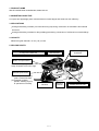
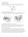
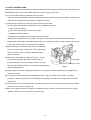
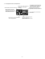
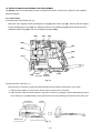
MODEL
VB 13Y
POWER TOOLS
PORTABLE REBAR CUTTER/BENDER
VB 13Y
TECHNICAL DATA
AND
SERVICE MANUAL
V
LIST No. 0782
Jan. 2000
SPECIFICATIONS AND PARTS ARE SUBJECT TO CHANGE FOR IMPROVEMENT
REMARK:
Throughout this TECHNICAL DATA AND SERVICE MANUAL, a symbol(s)
is(are) used in the place of company name(s) and model name(s) of our
competitor(s). The symbol(s) utilized here is(are) as follows:
Competitors
Symbols Utilized
Company Name
Model Name
S
MCC
CB-13
Y
ALBA
DR-12E
Notice for use
Specifications and parts are subject to change for improvement.
Refer to Hitachi Power Tool Technical News for further information.
CONTENTS
[ Business Section ]
1. PRODUCT NAME
Page
• • • • • • • • • • • • • • • • • • • • • • • • • • • • • • • • • • • • • • • • • • • • • • • • • • • • • • • • • • • • • • • • • • • • • • • • • • • • • • • • • • • • • • • • • • • • • • • • • • • • • • • • • • • • • • • • • • • • • • • •
2. MARKETING OBJECTIVE
• • • • • • • • • • • • • • • • • • • • • • • • • • • • • • • • • • • • • • • • • • • • • • • • • • • • • • • • • • • • • • • • • • • • • • • • • • • • • • • • • • • • • • • • • • • • • • • • • • • • • • • • • • •
1
• • • • • • • • • • • • • • • • • • • • • • • • • • • • • • • • • • • • • • • • • • • • • • • • • • • • • • • • • • • • • • • • • • • • • • • • • • • • • • • • • • • • • • • • • • • • • • • • • • • • • • • • • • • • • • • • • • • • • • • • • • •
1
• • • • • • • • • • • • • • • • • • • • • • • • • • • • • • • • • • • • • • • • • • • • • • • • • • • • • • • • • • • • • • • • • • • • • • • • • • • • • • • • • • • • • • • • • • • • • • • • • • • • • • • • • • • • • • • • • • • • • • • • • • • • • • •• •
1
3. APPLICATIONS
4. CAPACITY
1
5. SELLING POINTS
• • • • • • • • • • • • • • • • • • • • • • • • • • • • • • • • • • • • • • • • • • • • • • • • • • • • • • • • • • • • • • • • • • • • • • • • • • • • • • • • • • • • • • • • • • • • • • • • • • • • • • • • • • • • • • • • • • • • • • •
5-1. Selling Point Descriptions
6. SPECIFICATIONS
• • • • • • • • • • • • • • • • • • • • • • • • • • • • • • • • • • • • • • • • • • • • • • • • • • • • • • • • • • • • • • • • • • • • • • • • • • • • • • • • • • • • • • • • • • • • • • • • • • • • • • •
2
• • • • • • • • • • • • • • • • • • • • • • • • • • • • • • • • • • • • • • • • • • • • • • • • • • • • • • • • • • • • • • • • • • • • • • • • • • • • • • • • • • • • • • • • • • • • • • • • • • • • • • • • • • • • • • • • • • • • • • •
4
7. COMPARISONS WITH SIMILAR PRODUCTS
7-1. Working Efficiency Comparison
8. HOW TO USE THIS UNIT
• • • • • • • • • • • • • • • • • • • • • • • • • • • • • • • • • • • • • • • • • • • • • • • • • • • • • • • • • • • • • • • • • • • • • • • • • • • •
5
• • • • • • • • • • • • • • • • • • • • • • • • • • • • • • • • • • • • • • • • • • • • • • • • • • • • • • • • • • • • • • • • • • • • • • • • • • • • • • • • • • • • • • • • • • • • • •
5
• • • • • • • • • • • • • • • • • • • • • • • • • • • • • • • • • • • • • • • • • • • • • • • • • • • • • • • • • • • • • • • • • • • • • • • • • • • • • • • • • • • • • • • • • • • • • • • • • • • • • • • • • • •
6
9. SERVICE LIFE OF CUTTER
•••••••••••••••••••••••••••••••••••••••••••••••••••••••••••••••••••••••••••••••••••••••••••••••••••••••
10. PRECAUTIONS IN SALES PROMOTION
7
• • • • • • • • • • • • • • • • • • • • • • • • • • • • • • • • • • • • • • • • • • • • • • • • • • • • • • • • • • • • • • • • • • • • • • • • • • • • • • • • •
7
• • • • • • • • • • • • • • • • • • • • • • • • • • • • • • • • • • • • • • • • • • • • • • • • • • • • • • • • • • • • • • • • • • • • • • • • • • • • • • • • • • • • • • • • • • • • • • • • • • • • • • • • • • • •
7
•••••••••••••••••••••••••••••••••••••••••••••••••••••••••••••••••••••••••••••••••••••••••••••••••••••••••••••••••••••••
7
10-1. Handling Instructions
10-2. Caution Plate
1
11. SAFETY INSTRUCTIONS
•••••••••••••••••••••••••••••••••••••••••••••••••••••••••••••••••••••••••••••••••••••••••••••••••••••••••
11-1. Pictograph Illustration and Explanation
• • • • • • • • • • • • • • • • • • • • • • • • • • • • • • • • • • • • • • • • • • • • • • • • • • • • • • • • • • • • • • • • • • • • • • • • • • • • • • • • • •
8
9
[ Service Section ]
12. PRECAUTIONS IN DISASSEMBLY AND REASSEMBLY
• • • • • • • • • • • • • • • • • • • • • • • • • • • • • • • • • • • • • • • • • • • • • • • • • • • • • • • •
10
12-1. Disassembly
• • • • • • • • • • • • • • • • • • • • • • • • • • • • • • • • • • • • • • • • • • • • • • • • • • • • • • • • • • • • • • • • • • • • • • • • • • • • • • • • • • • • • • • • • • • • • • • • • • • • • • • • • • • • • • • • • • • • • • •
10
12-2. Reassembly
• • • • • • • • • • • • • • • • • • • • • • • • • • • • • • • • • • • • • • • • • • • • • • • • • • • • • • • • • • • • • • • • • • • • • • • • • • • • • • • • • • • • • • • • • • • • • • • • • • • • • • • • • • • • • • • • • • • • • • • •
15
12-3. Wiring Diagram
•••••••••••••••••••••••••••••••••••••••••••••••••••••••••••••••••••••••••••••••••••••••••••••••••••••••••••••••••••••
12-4. Confirmation after Reassembly
16
• • • • • • • • • • • • • • • • • • • • • • • • • • • • • • • • • • • • • • • • • • • • • • • • • • • • • • • • • • • • • • • • • • • • • • • • • • • • • • • • • • • • • • • • • • • • •
17
12-5. Repair Procedure
• • • • • • • • • • • • • • • • • • • • • • • • • • • • • • • • • • • • • • • • • • • • • • • • • • • • • • • • • • • • • • • • • • • • • • • • • • • • • • • • • • • • • • • • • • • • • • • • • • • • • • • • • • • • • • • • •
19
12-6. Tightening Torque
• • • • • • • • • • • • • • • • • • • • • • • • • • • • • • • • • • • • • • • • • • • • • • • • • • • • • • • • • • • • • • • • • • • • • • • • • • • • • • • • • • • • • • • • • • • • • • • • • • • • • • • • • • • • • • • • •
20
12-7. Insulation Tests
• • • • • • • • • • • • • • • • • • • • • • • • • • • • • • • • • • • • • • • • • • • • • • • • • • • • • • • • • • • • • • • • • • • • • • • • • • • • • • • • • • • • • • • • • • • • • • • • • • • • • • • • • • • • • • • • • • • •
12-8. No-load Current Value
• • • • • • • • • • • • • • • • • • • • • • • • • • • • • • • • • • • • • • • • • • • • • • • • • • • • • • • • • • • • • • • • • • • • • • • • • • • • • • • • • • • • • • • • • • • • • • • • • • • • • • • • • •
13. STANDARD REPAIR TIME (UNIT) SCHEDULES
• • • • • • • • • • • • • • • • • • • • • • • • • • • • • • • • • • • • • • • • • • • • • • • • • • • • • • • • • • • • • • • • • • • • •
20
20
21
[ Appendix ]
Assembly Diagram for VB 13Y
••••••••••••••••••••••••••••••••••••••••••••••••••••••••••••••••••••••••••••••••••••••••••••••••••••••
22
1. PRODUCT NAME
Hitachi Portable Rebar Cutter/Bender, Model VB 13Y
2. MARKETING OBJECTIVE
A compact and lightweight power tool that reduces worker fatigue and enhances work efficiency.
3. APPLICATIONS
Cutting and bending of rebars (concrete reinforcing rod) during construction of foundations and external
structures.
Cutting and bending of rebars for fitting building parts during construction of reinforced concrete buildings.
4. CAPACITY
Reinforcing bar diameter: 13 mm (1/2") or less
5. SELLING POINTS
Lightweight, compact and therefore easy
to carry to the work site
Motorized for
reduced effort
Hole for bolting to a
fixed base
Built-in microprocessor
Uniform bending angles over a wider
range of speeds, from low to high
Variable-speed switch
(1) Hand-adjustable bending
(with a manual-like feel)
(2) Operable at slower
speeds, enabling anyone
to operate it more easily
Double-insulated
structure
--- 1 ---
Reaction
receiver
Both cutting and bending
possible with one unit
5-1. Selling Point Descriptions
5-1-1. Motorized for reduced effort
A manual cutter/bender requires the worker to overcome a load of 392 to 490 N (40 to 50 kgf) to bend or cut a
rebar of 13 mm (1/2") diameter. The Model VB 13 Y can reduce worker fatigue because it is motorized.
Manual cutter/bender
Load
Fig. 1
5-1-2. Both cutting and bending possible with one unit
Both a cutter and a bender are required if each tool has only a single function (cutting or bending). The Model VB
13Y can perform both cutting and bending with one unit in the same manner as a manual cutter/bender.
Rebar
Rebar
Cutter
Variable-speed switch
Bending roller
Fig. 2 Cutting
Fig. 3 Bending
5-1-3. Lightweight, compact and therefore easy to carry to the work site
The reason why manual cutter/benders have achieved widespread use in construction sites is that they are
compact and lightweight. The Model VB 13Y is attractively convenient for carrying to work sites because the
weight is almost the same as a manual cutter/bender (12.0 kg (26.5 lbs.)) while the size is smaller.
5-1-4. Excellent cost/performance ratio
The Model VB 13Y is about two-thirds or half the price of ordinary electric cutters or benders which have only
single functions while the Model VB 13Y can perform both cutting and bending (13 mm (1/2") dia. rebar) with one
unit. If comparisons are made with another maker's electro-hydraulic cutter/benders (capacity rebar dia. 16 mm
(5/8")), the Model VB 13Y is half the price of the electro-hydraulic cutter/bender and the cost/performance ratio is
excellent. This is because the Model VB 13Y is equipped with a gear and a cam instead of a hydraulic system for
cutting rebars, and an advanced microprocessor instead of an electromagnetic clutch for bending rebars.
--- 2 ---
5-1-5. Variable-speed switch
A manual cutter/bender has an advantage of hand-adjustable bending by eye measurement. Since the Model
VB 13Y uses a variable-speed switch, rebars can also be bent to the desired angles by eye measurement with a
manual-like feel while the conventional electric bender provides only a fixed-speed bending. The operator can
easily vary the bending speed depending on how far the switch trigger is depressed. These features make the
Model VB 13Y convenient for bending work at construction sites.
5-1-6. Built-in microprocessor
The Model VB 13Y is equipped with a microprocessor for uniform bending angles over a wider range of speeds
from low to high. Rebars can be bent according to the angles selected with the setting dial even if the bending
speed is varied. The Model VB 13Y provides uniform bending results regardless of speeds and the motor's
inertial force.
5-1-7. Double-insulated structure
The Model VB 13Y has double-insulated structure for safety in use outdoors or below the ground.
5-1-8. Reaction receiver
There is a need to prevent movement of the unit caused by cutting 5 m (197")-long rebars generally used in
construction sites. The Model VB 13Y has two reaction receivers at the front and the rear for stable operation.
5-1-9. Hole for bolting to a fixed base
A hole is provided at the center of the unit to fix and stabilize it. This hole comes in quite handy for bending
operations because it allows the unit to be bolted to a suitable work bench (bolt size M10, less than W3/8).
5-1-10. Low height
The Model VB 13Y has a unique design, with the bending unit being lower than the motor unit, to give the bender
added stability when bending long rebars. Although the maximum capacity rebar diameter is smaller than another
maker's electric cutter/bender, the Model VB 13Y is convenient to use thanks to its lower height (135 mm (5-5/
16")) while the other maker's electric cutter/bender is 245 mm (9-41/64") high.
5-1-11. Center plate with marking for bending position adjustment
The Model VB 13Y eliminates manual marking work
required for bending rebars with a manual cutter/bender
Center plate
Marked lines
because the center plate has reference markings for
Rebar
easy bending position adjustment.
Bending roller
Fig. 4
--- 3 ---
6. SPECIFICATIONS
VB 13Y
Model
(1) Material; Rebar: Yield strength 460N/mm2 (47 kgf/mm2) max.
Capacities
GRADE 460 (Great Britain)
BST 500 (Germany)
B 500 (Spain)
GRADE 40 (U.S.A.)
or equivalent grades
(2) Diameter of material: 8 --- 13 mm (3/8" --- 1/2"))
Cutting
Number of piece that can be
processed at one time
Bending
10 mm (3/8") max.
• • • • •
1 piece
10 mm (3/8") max.
• • • • •
2 pieces
13 mm (1/2") max.
• • • • •
1 piece
13 mm (1/2") max.
• • • • •
1 piece
Motor type
AC single-phase series commutator motor
Enclosure
Materials: Aluminum alloy die cast
Glass-fiber reinforced resin (Housing, handle, tail cover)
Painting: Silver, light green, black
Insulation structure
Double insulation
Switch
Speed control switch
Power source
Single-phase AC 50 Hz
Voltage and current
1.3 A (230 V)
Power input
285 W
Rotation speed
0 --- 16 /min.
Weight
Net
Product: 12.0 kg (26.5 lbs.); excluding cord
Gross
Packed: 13.1 kg (28.9 lbs.)
Packaging
Cord
Corrugated cardboard box
Type
Two core cabtire cable
Overall length
2.5 m (8.2 ft.)
Standard accessories
Allen key (for M5 hexagon socket bolt)
One set of cutters
• • • • • • • • • • • • • • • • • • • • • • • • • • • • • • • • • • • • •
1 pc.
• • • • • • • • • • • • • • • • • • • • • • • • • • • • • • • • • • • • • • • • • • • • • • • • • • • • • • • • • • • • • • • • • • • •
1 set.
--- 4 ---
7. COMPARISONS WITH SIMILAR PRODUCTS
Specification Comparisons
Maker
HITACHI
Model name
VB13Y
S
Y
Power Input
W
285
Power Output
W
300
/min
16
Length
mm
430
(16-15/16")
1,050
(41-3/8")
950
(37-7/16")
Height
mm
196
(7-3/4")
115
(4-17/32")
250
(9-27/32")
Width
mm
197
(7-3/4")
220
(8-21/32")
135
(5-5/16")
11.5
(25.4 Ibs.)
12.3
(27.1 Ibs.)
S
Y
13
(1/2")
13
(1/2")
13
(1/2")
Motorized gear
drive system
Manual
Manual
Rotation Speed
Dimensions
Double
Insulation
Insulation Structure
Full-load vibration level
dB (VL)
91.4
No-load Noise Level
dB (A)
79
kg
12.0
(26.5 Ibs.)
Weight
(excluding cord)
7-1. Working Efficiency Comparison
Maker
HITACHI
Model name
VB 13Y
Capacity Rebar Dia.
mm
Drive System
Cutting Time
seconds/operation
3.2
*10
Bending Time (180˚)
seconds/operation
4
*15
13
* The data shown in the above table are mean values of 50 bending operations. (The cutting time and
bending time may vary in accordance with operating conditions such as the load to be applied.)
The cutter/bender sketched below is also used in Europe.
Manual cutter/bender
Load
Load
Fig. 5
Fig. 6
--- 5 ---
8. HOW TO USE THIS UNIT
(1) Cutting work (Fig. 7)
Rebar
Cutter
Variable-speed switch
Fig. 7
Alignment marks
Setting dial
(2) Bending work (Fig. 8)
Rebar
To switch between cutting and bending
To adjust bending angle (0 fl --- 180 fl)
Fig. 7, 8-a
Fig. 8
Bending roller
Variable-speed switch
--- 6 ---
9. SERVICE LIFE OF CUTTER
The life of a cutter edge is rated at 2,500 operations. (5,000 operations using both edges of each cutter blade).
When the edge of a cutter is worn out or deformed, turn the cutter around so that the other edge is properly set or
replace the cutter with new one.
10. PRECAUTIONS IN SALES PROMOTION
In the interest of promoting the safest and most efficient use of the Model VB 13Y Portable Rebar Cutter/Bender
by all of our customers, it is very important that at the time of sale the salesperson carefully ensures that the buyer
seriously recognizes the importance of the contents of the Handling Instructions, and fully understands the
meaning of the precautions listed on the Caution Plate attached to each tool.
10-1. Handling Instructions
Salespersons must be thoroughly familiar with the contents of the Handling Instructions in order to give pertinent
advice to the customer. In particular, they must have a thorough understanding of the precautions for use of the
portable rebar cutter/bender which is different from those of ordinary electric power tools.
10-2. Caution Plate
Each Model VB 13Y unit is provided with a Caution Plate (illustrated below) which lists basic safety precautions in
its use. Carefully ensure that the customer fully understands and follows these precautions before using the tool.
For Europe and the other
--- 7 ---
11. SAFETY INSTRUCTIONS
Be particularly careful to ensure that the customer understands the following precautions which are listed on the
Handling Instructions and Caution Plates attached to the main body of each tool.
(1) Do not cut and/or bend any materials other than rebar.
Avoid any work exceeding the maximum capacities of the unit described in the specifications. Otherwise, the
cutter can be damaged and the material can shatter into pieces.
(2) While turning the switch on, never put your hand close to the cutter.
For the sake of safe operation, the Model VB 13Y is designed as follows:
Cutter cover is provided.
Gear cover prevents finger access to the cutter.
Bending unit has no opening.
Bending unit is designed so that fingers cannot be inserted.
Although these safety measures are taken, the opening of the cutter must be exposed for workability.
Unintentional starting with fingers touching the cutter can cause serious injury. Never bring your hand close
to the cutter while the plug is connected to a receptacle.
(3) Make absolutely sure that the cutter cover is closed when
you are not carrying out cutting work. If the cover is kept
open, the cutter can jam on foreign objects and cause
serious accidents.
(4) Reserve an extra length of at least 120 mm (4 --- 23/32")
Extra length
on the bending length of the rebar to be bent (Fig. 9).
If the extra length is not long enough, the rebar can come
120 mm (4 --- 23/32") or more
off during the bending operation, or it can break into fragments
Fig. 9
and scatter dangerously.
(5) Begin operation only after making sure that there are no people or objects within the turning range of the
material to be bent.
(6) If the switch is turned off and then immediately turned on again, the motor may not start, as a safety
precaution. Wait for at least one full second before attempting to turn the motor on again after it has been
switched off.
(7) Note that the unit is not a hand-held tool. Be absolutely sure to use the unit only after placing it on a stable
surface such as a floor, the ground, etc.
(8) Be sure to unplug the power cord from the receptacle when the cutter is being checked, cleaned, or parts
replaced. Failure to do so can result in a serious injury.
--- 8 ---
11-1. Pictograph Illustration and Explanation
Do not use or leave this electric
power tool in wet weather
Read handling instructions before use. conditions.
Begin operation only after
making sure that there are no
people within the turning range
of the material to be bent.
Never bring your hand close to the
cutter during operation.
If the switch is turned off and then
immediately turned on again, the
motor may not start. Wait for at
least one full second before
attempting to turn the motor on
again after it has been switched off.
Do not attempt to cut two rebars
at one time.
Avoid any work exceeding the
maximum capacities.
(Rebar diameter 13 mm (1/2") )
--- 9 ---
12. PRECAUTIONS IN DISASSEMBLY AND REASSEMBLY
The [Bold] numbers in the descriptions below correspond to the item numbers in the Parts List and exploded
assembly diagram.
12-1. Disassembly
(1) Disassembly of the handle (Fig. 10)
Remove the two Tapping Screws (W/Flange) D4 x 20 [81] and the Tail Cover [82]. Remove the two Tapping
Screws (W/Flange) D5 x 20 [104], four Tapping Screws D4 x 20 (W/Flange) [81] and two Machine Screws
(W/Washers) M5 x 20 [105] to remove the Handle (A).(B) Set [94].
[82]
[81]
[98]
[86]
[95]
[88]
[94]
[13]
[81]
[104]
[105]
Cable
Rubber
[22] connector
bushing
Cable
Fig. 10
(2) Removal of the cable (Fig. 11)
Disconnect the connector by pulling the rubber bushing and the cable in the direction of the arrow.
*1. Gently pull the cable by moving it from side to side to disconnect the connector.
*2. If the one part of the connector remains in the gear cover due to yanking the cable, disassemble the gear
cover referring to "(5) Disassembly of the gear" and remove the remaining connector from the gear cover.
Connector
Cable
Rubber bushing
Gear cover
Fig. 11
--- 10 ---
(3) Disassembly of the power supply unit
1) Removal of the Controller Circuit [95] (Fig. 10)
Remove the rubber bushing and pull out the cable of the Controller Circuit [95] from the Gear Cover Ass'y
[22]. Disconnect the cable connector from the cable and separate the Controller Circuit [95] from the Gear
Cover Ass'y [22]. (The cable connector can be disconnected by pulling it out with hands.) Disconnect the
Connector [98] which connects the seven internal wires with the Stator Ass'y [88].
2) Disassembly of the housing
Remove the Brush Cap [76] and take out the Carbon Brush [77]. Remove the four Hex. Socket Hd. Bolts
(W/Flange) M5 x 30 [79] from the Housing Ass'y [86]. The Housing Ass'y [86] can then be removed from
the Inner Cover Ass'y [13].
(4) Disassembly of the bending unit (Fig. 12)
1) Remove the Hex. Socket Hd. Bolt M5 x 12 [1], Hex. Socket Hd. Bolt (W/Flange) M5 x 16 [29] and the
Center Plate (A) [3].
2) Remove the Hex. Socket Hd. Bolt M5 x 12 [1] and the Roller (B) [30].
3) Remove the Lever (A) [31], Turn Table [5] and the five Flat Hd. Screws M4 x 10 [32] to remove the Cam
Cover [6].
[31]
[1]
[29]
[3]
[32]
[6]
[5]
[1]
Fig. 12
--- 11 ---
[30]
(5) Disassembly of the gear (Figs. 13, 14 and 15)
1) Remove the two Hex. Socket Hd. Bolts (W/Flange) M4 x 10 [58] from the bottom of the Gear Cover Ass'y
[22] and remove the Sensor Cover [28] and the O-Ring (S-85) [27].
2) Mark the engagement point between the Sensor Gear [26] and the Sensor Gear [56] with a magic marker
as shown in Fig. 13-b. Then, remove the Seal Lock Screw (W/SP. Washer) M4 x 12 [36] and Washer (B)
[57] to remove the Sensor Gear [56] (Fig. 13).
[58]
Mark the engagement
point before disassembly.
[28]
Projection
[36]
[56]
[29]
Fig. 13-b Disassembly
[57]
[23]
[24]
Fig. 13-a
[26]
The number of teeth
between the point B
and the projection
should be the same.
B (Engagement point)
* Marking should be made for easy reassembly. Otherwise,
Adjust the position
of the protrusions by
turning the gear.
adjust the sensor gears so that the number of teeth between
the engagement point and the projection is the same each
Fig. 13-c Reassembly
other as shown in Fig. 13-c and then mount them.
Fig. 13
3) Remove the seven Hex. Socket Hd. Bolts (W/Flange) M5 x 16 [29] and the Gear Cover Ass'y [22].
Then First Pinion (B) [55], Second Pinion [47] and Third Pinion [43] can be removed. The Final Gear [18]
can be removed by removing the Retaining Ring for D25 Shaft [19]. If it is hard to remove the Final Gear
[18], use a bearing puller for removal. The Cam Shaft [12] can be removed just by pulling upward (toward
Cam Cover [6]) if the Final Gear [18] has already been removed.
[29]
[28]
[22]
[56]
[36]
[57]
[27]
Not removable
[58]
Fig. 14
--- 12 ---
[18]
[19]
[12]
Third Pinion
Second Pinion
First Pinion (B)
Fig. 15
(6) Disassembly of the gear unit (Figs. 16, 17 and 18)
1) Press First Pinion (B) [55] in A direction with a hand press supporting the surfaces B and C respectively.
Then remove Sleeve (B) [50], First Gear (B) [51], Clutch Spring [52], Collar (A) [53] and Washer [54] (Fig.
16).
2) Remove the Second Pinion [47] from the Second Gear [48] by pressing with a hand press (Fig. 17).
3) Remove the Feather Key [44] and the Third Pinion [43] from the Third Gear [45] by pressing with a hand
press (Fig. 18).
A
[52]
[50]
[47]
[51]
[43]
[44]
Press-fitted
B surface
[54]
C surface
[48]
Press-fitted
[53]
[45]
[55]
Fig. 16
Fig. 17
Fig. 18
(7) Removal of bracket (A), bracket (B) and covers (Figs. 19 and 20)
1) Remove the Seal Lock Screw (W/SP. Washer) M4 x 12 [36] and Thrust Washer [37] that fix the Return
Spring [38] from the upper surface of the Inner Cover Ass'y [13]. Then remove the Return Spring [38] from
the Inner Cover [13] (by prying it off with a flat-blade screwdriver).
2) Remove the two Hex. Socket Hd. Bolts M5 x 16 [67] and the Flange Nut M12 [39] from the inside of the
Inner Cover Ass'y [13]. Then remove Bracket (A) [68], Bracket (B) [73], Cover [63] and O-Ring (S-34) [64]
from the Inner Cover [13].
--- 13 ---
[13]
[38]
[63]
Hook
[64]
[36]
[13]
[68]
[73]
[37]
[34]
[39]
[67]
[66] [65]
[67]
Fig. 19
Fig. 20
(8) Disassembly of bracket (A) and (B) unit (Fig. 20)
Press the Bolt (A) [65] with a hand press supporting Bracket (A) [68]. Then the Feather Key [66], Bracket (A)
[68] and Bracket (B) [73] can be removed.
(9) Disassembly of bracket (A) unit (Fig. 21)
1) Remove the Retaining Ring for D9 Shaft [61]. Then the Pin for Spring [72], Spring (C) [71] and Cutter
Guard [70] can be removed.
2) Pull out the Needle [60] with a hand press to remove Roller (C) [62] from Bracket (A) [68].
[72]
[71]
[62]
[70]
[61]
[68]
[60]
Fig. 21
(10) Disassembly of the cam shaft unit (Fig. 22)
Remove the Cam [8] and two Feather Keys [34] from the Cam Shaft [12] with a hand press.
--- 14 ---
12-2. Reassembly
Reassembly can generally be carried out as the reverse of
the disassembly procedure, with some items to be noted as
follows.
(1) Reassembly of the cam shaft unit (Fig. 22)
Perform reassembly so that the chamfered portion of the
[34]
Pin
Cam Shaft [12] is aligned with the pins of the Cam [8] in
the same direction.
[8]
* Otherwise, the Sensor Gear [56] cannot be mounted in
Same direction
the proper position and damage to the volume and the
gear will result. Be sure to check the mounting direction
[12]
after reassembly.
Chamfered portion
(2) Reassembly of bracket (A) unit (Fig. 23)
Mount Bracket (A) [68] to Spring (C) [71] so that the
Fig. 22
folded portion of Spring (C) [71] securely fits in the notch
of the Cutter Guard [70] (Fig. 23). Apply grease
(TUFREX 251) to the hole of Roller (C) [62] adequately
[70]
[68]
[72]
(Fig. 24).
[71]
(3) Reassembly of bracket (A) and (B) unit (Fig. 24)
Mount the Bolt (A) [65] to Bracket (A) [68]. Apply grease
[62]
(TUFREX 251) to the shaded areas shown in Fig. 24
adequately. Mount the Feather Key [66] to Bracket (A)
Folded portion
[68] and press-fit it to Bracket (B) [73].
Fig. 23
(4) Installation of bracket (A) and (B) unit to the inner cover
(Figs. 19 and 20)
Mount bracket (A) and (B) unit into the Inner Cover Ass'y
[13] and secure it with two Hex. Socket Hd. Bolts M5 x 16
[67] and the Flange Nut M12 [39]. Hook one end of the
[65]
[60]
[61]
[66]
[68]
[62]
Return Spring [38] in the groove of the Pin for Spring [72]
and the other end on the projection of the Inner Cover
Ass'y [13]. Secure it with the Thrust Washer [37] and the
[70]
Apply grease.
[69]
[71]
[72]
Seal Lock Screw (W/SP. Washer) M4 x 12 [36].
[69]
* For easy reassembly, mount the Return Spring [38] first
[73]
before mounting the Cam Shaft [12]. Use a flat-blade
[67]
screwdriver for mounting the Return Spring [38].
Fig. 24
--- 15 ---
[67]
(5) Reassembly of bending unit (Figs. 12 and 22)
Mount the Cam Cover [6], Turn Table [5] and Center Plate (A) [3] in the reverse of the disassembly procedure.
Before mounting the Center Plate (A) [3], apply grease (TUFREX 251) to the 18 mm dia. hole of Center Plate
(A) [3] adequately. Check that the hole of the Turn Table [5] and the pin of the Cam [8] are properly adjusted
to ensure smooth movement of Roller (B) [30].
(6) Installation of gears
Apply grease (Nippeko SEP-3A) to the meshing parts of First Pinion (B) [55], Second Pinion [47], Third Pinion
[43] and Final Gear [18], and mount them in the reverse of the disassembly procedure. Apply grease
(TUFREX 251) to the Clutch Spring [52], Collar (A) [53] and the boss of First Gear (B) [51] adequately. Check
that the Sensor Holder Ass'y [23] is mounted and the wiring is completed. Secure the Inner Cover Ass'y [13]
and the Gear Cover Ass'y [22] with seven Hex. Socket Hd. Bolts (W/Flange) M5 x 16 [29].
* Perform wiring of the Sensor Holder Ass'y [23] in this step. Wiring in later step is impossible though the
Sensor Holder Ass'y [23] is secured with the Tapping Screw D3 x 12 [24] in the next step (Fig. 13-a).
(7) Installation of the Sensor Gear [56] (Fig. 13)
Mount the Sensor Gear [56] in the reverse of the disassembly procedure shown in 12-1 (5) 2). Pay attention
to the mounting position of the Sensor Gear [56].
12-3. Wiring Diagram
Be sure to perform wiring connections as indicated in the wiring diagrams.
For products without noise suppressor
Switch
Stator
Stator
Cord
Armature
Printed Circuit
Board Ass'y
Control Circuit Ass'y
Fig. 25
--- 16 ---
For products with noise suppressor
CR Unit
(0.022 µF + 5 KΩ)
Switch
Stator
Choke Coil
8 µH
Cord
Printed Circuit
Board Ass'y
Armature
Choke Coil
5 µH
CR Unit
(0.022 µF + 5 KΩ)
Stator
Control Circuit Ass'y
Capacitor
(0.22 µF + 2 x 3300 pF)
Fig. 26
12-4. Confirmation after Reassembly
(1) Check the accuracy with an angle gauge (Figs. 27, 28 and 29).
1) Adhere an angle gauge to the Turn Table [5] (Fig. 27).
2) Turn the Volume Holder Ass'y [100] (bending angle selector) clockwise until it is locked (Fig. 28).
3) Pull the trigger slightly to run the machine as slow as possible.
4) It is all right if the Turn Table [5] starts backward rotation from the marked line for 13 mm dia. bar with the
marking on the angle gauge aligned (Fig. 29).
5) If the marking on the angle gauge is not aligned with the marked line for 13 mm dia. bar, perform
adjustment according to the next step (2).
<Initial position>
[5]
Angle gauge
Align with the perimeter.
Fig. 27
--- 17 ---
<Starting position for backward rotation>
Marked line for 13 mm dia. bar
Marking on the angle gauge
[100]
Check the starting position for backward rotation.
Fig. 29
Fig. 28
(2) Adjust the bending accuracy as follows (Fig. 30).
1) Unplug the power cord from the receptacle.
2) Slightly turn the fine-adjustment control on the Controller Circuit [95] with a screwdriver.
3) Plug the power cord in the receptacle and check the accuracy again with an angle gauge. Repeat the
adjustment until the marking is aligned.
* Be sure to unplug the power cord from the receptacle before touching the circuits for safety's sake.
<Locations of marking and marked line>
<Turning direction>
Marked line for 13 mm dia. bar
Right
Marking on the angle gauge
Fine-adjustment control
Small rotation angle
Left
Large rotation angle
Fig. 30
--- 18 ---
12-5. Repair Procedure
Following table shows rough repair procedures. Refer to the above mentioned disassembly and reassembly
procedures for details.
* Be sure to confirm the operation of the controller circuit, gears, brackets and cam after reassembly of them, and
perform adjustment if necessary.
No.
1
Item
Replacement of
control circuit
Procedure
12-1 (1) Disassembly of the handle
12-1 (2) Removal of the cable
Remarks
Wiring of the controller
circuit
* Refer to "12-3. Wiring
Diagram".
Confirmation after reassembly
* Refer to 12-4 (1) and (2).
12-1 (3) Disassembly of the power supply unit
12-2 Reassembly
12-4 Confirmation after Reassembly
2
Replacement of gears,
brackets and cam
12-1 (1) Disassembly of the handle
12-1 (2) Removal of the cable
12-1 (4) Disassembly of the bending unit (Fig. 12)
Removal of sensor gear
Disassembly of the gear unit,
bracket unit and cam unit
12-2 Reassembly
12-4 Confirmation after Reassembly
--- 19 ---
Removal and installation of
the sensor gear
* Refer to 12-1 (5) and 12-2
(6).
Confirmation after reassembly
* Refer to 12-4 (1) and (2).
12-6. Tightening Torque
Machine Screw (W/Washers)
M5
3.4
0.7 N•m (35
7 kgf•cm) (30.4
6.1 in-Ibs.)
Seal Lock Screw
M4
1.8
0.4 N•m (18
4 kgf•cm) (15.6
3.5 in-Ibs.)
Machine Screw
Machine Screw (for the Sensor Gear only)
M4
1.8 0.4 N•m (18 4 kgf•cm) (15.6 3.5 in-Ibs.)
1 0.2 N•m (10 2 kgf•cm) (8.7 1.7 in-Ibs.)
Flange Nut
M12
39.2
Tapping Screw (W/Flange)
D5
2.9
0.5 N•m (30
5 kgf•cm) (26
Tapping Screw (W/Flange)
D4
2.0
0.5 N•m (20
5 kgf•cm) (17.4
4.3 in-Ibs.)
Hex. Socket Hd. Bolt
M5
5.9
1.5 N•m (60
15 kgf•cm) (52
13 in-Ibs.)
Hex. Socket Hd. Bolt
M4
3.4
0.7 N•m (35
7 kgf•cm) (30.4
6.1 in-Ibs.)
7.8 N•m (400
80 kgf•cm) (347.2
4.3 in-Ibs.)
12-7. Insulation Tests
On completion of disassembly and repair, measure the insulation resistance and dielectric strength.
Insulation resistance: 7 MΩ or more with DC 500 V megohm tester
Dielectric strength: AC 4000 V/1 minute, with no abnormalities .... 230 V
12-8. No-load Current Value
After no-load operation for 30 minutes, the no-load current value should be as follows.
Voltage
Current (Max.)
230 V
1.3
--- 20 ---
69.4 in-Ibs.)
13. STANDARD REPAIR TIME (UNIT) SCHEDULES
MODEL
Variable
Fixed
10
20
30
40
50
70 min.
Work Flow
VB 13Y
Tail Cover
Handle (A).(B)
Set
Controller
Circuit
O-Ring
Volume Holder
Ass'y
Steel Bar
Switch Rubber
Guide
Cover
Switch
Cord Armor
Cord
Rubber
Bushing
Housing Ass'y
Bearing
Bushing (B)
Ball Bearing
(608VV) x 2
Stator Ass'y
Fan Guide
Armature
General Assembly
Sensor Cover Gear Cover
Final Gear
Ass'y Ball Bearing
O-Ring (S-85)
(6201VV)
Sensor Gear
Sensor Holder
Ass'y
Center Plate
Roller (B)
O-Ring (P-18)
Turn Table
Lever
Cam Cover
Felt Packing
x2
Cover
O-Ring (S-34)
Dust Guard
First Pinion
Ball Bearing
(608VV)
Clutch Spring
First Gear
Metal
Second Pinion
Second Gear
Ball Bearing
(608VV)
Metal
Third Pinion
Feather Key
(5 x 5 x 10)
Third Gear
Metal (B)
Ball Bearing
(6301VV)
--- 21 ---
Cam
Inner Cover
Ass'y
Lock Pin (B)
V-Ring
Cam Shaft
Feather Key
(7 x 7 x 15) x 2
Return Spring
Bolt (A)
Feather Key
(4 x 4 x 8)
Bracket (A)
Cutter Guard
Spring (C)
Pin for Spring
Bracket (B)
Needle
Roller (C)
Assembly Diagram for VB 13Y
--- 22 ---
VB 13Y
PARTS
ITEM
NO.
1
CODE NO.
DESCRIPTION
NO.
USED
2
998-471
HEX. SOCKET HD. BOLT M5X12
2
316-224
WASHER
2
3
318-288
CENTER PLATE (A)
1
4
873-570
O-RING (P-18)
1
5
316-220
TURN TABLE
1
6
316-219
CAM COVER
1
7
316-216
FELT PACKING
1
8
316-199
CAM
1
9
939-540
RETAINING RING FOR D10 SHAFT (10 PCS.)
1
10
316-201
LOCK PIN (B)
1
11
316-198
V-RING
1
12
316-200
CAM SHAFT
1
13
316-184
INNER COVER ASS’Y
1
14
316-225
STAND
1
15
931-701
BEARING LOCK
1
16
316-195
HEX. SOCKET HD. BOLT (W/FLANGE) M5X20
2
17
630-1VV
BALL BEARING 6301VVCMPS2L
1
18
316-202
FINAL GEAR
1
19
965-469
RETAINING RING FOR D25 SHAFT
1
REMARKS
INCLUD.17,35,41,42
20
620-1VV
BALL BEARING 6201VVCMPS2L
1
21
316-451
PIN D18
1
22
316-211
GEAR COVER ASS’Y
1
INCLUD.20,21,46,49
23
318-284
SENSOR HOLDER ASS’Y
1
INCLUD.24,56
24
316-214
TAPPING SCREW D3X12
1
25
949-215
MACHINE SCREW M4X8 (10 PCS.)
2
26
316-212
SENSOR GEAR
1
27
985-227
O-RING (S-85)
1
28
316-215
SENSOR COVER
1
29
994-192
HEX. SOCKET HD. BOLT (W/FLANGE) M5X16
9
30
316-223
ROLLER (B)
1
31
318-287
LEVER (A)
1
32
949-322
FLAT HD. SCREW M4X10 (10 PCS.)
5
33
316-217
FELT PACKING
1
34
306-506
FEATHER KEY 7X7X15
4
35
316-186
SUPPORT (B)
1
36
987-203
SEAL LOCK SCREW (W/SP. WASHER) M4X12
2
37
875-249
THRUST WASHER
1
38
316-197
RETURN SPRING
1
39
316-196
FLANGE NUT M12
1
40
307-607
WRENCH HOLDER
1
41
316-185
METAL
1
42
954-940
METAL D8X10
1
43
316-203
THIRD PINION
1
44
948-015
FEATHER KEY 5X5X10
1
45
316-204
THIRD GEAR
1
46
954-789
METAL (B)
1
47
316-205
SECOND PINION
1
48
316-206
SECOND GEAR
1
49
608-VVM
BALL BEARING 608VVC2PS2L
2
50
318-360
SLEEVE (B)
1
51
318-358
FIRST GEAR (B)
1
PARTS
* : ALTERNATIVE
--- 23 ---
9 --- 99
VB 13Y
PARTS
ITEM
NO.
52
CODE NO.
316-209
DESCRIPTION
CLUTCH SPRING
NO.
USED
1
53
316-208
COLLAR (A)
1
54
981-077
WASHER
1
55
318-359
FIRST PINION (B)
1
56
316-212
SENSOR GEAR
1
57
962-569
WASHER (B)
1
58
316-228
HEX. SOCKET HD. BOLT (W/FLANGE) M4X10
2
59
316-226
STEEL BAR GUIDE
1
60
316-190
NEEDLE
1
61
992-805
RETAINING RING FOR D9 SHAFT
1
62
316-189
ROLLER (C)
1
63
318-285
COVER
1
64
980-879
O-RING (S-34)
1
65
316-194
BOLT (A)
1
66
980-809
FEATHER KEY 4X4X8
1
67
949-821
HEX. SOCKET HD. BOLT M5X16 (10 PCS.)
2
68
316-188
BRACKET (A)
1
69
316-235
CUTTER (1 PAIR)
2
70
316-191
CUTTER GUARD
1
71
316-192
SPRING (C)
1
72
316-193
PIN FOR SPRING
1
73
316-187
BRACKET (B)
1
74
316-222
DUST GUARD
1
75
938-477
HEX. SOCKET SET SCREW M5X8
2
76
935-829
BRUSH CAP
2
77
999-043
CARBON BRUSH (1 PAIR)
2
78
971-001
BRUSH HOLDER
2
79
313-585
HEX. SOCKET HD. BOLT (W/FLANGE) M5X30
4
80
318-286
CAUTION PLATE (E)
1
81
301-653
TAPPING SCREW (W/FLANGE) D4X20 (BLACK)
6
82
316-227
TAIL COVER
1
83
310-111
BEARING BUSHING (B)
1
84
318-362
BALL BEARING (A)
2
HITACHI LABEL
1
85
86
310-146
HOUSING ASS’Y
1
87
930-703
BRUSH TERMINAL
2
88
340-419E
STATOR ASS’Y 230V
1
89
990-861
INTERNAL WIRE
1
90
980-864
HEX. HD. TAPPING SCREW D5X40
2
91
980-931
FAN GUIDE
1
92
360-470E
ARMATURE 230V
1
NAME PLATE
1
94
316-234
HANDLE (A).(B) SET
1
95
318-282
CONTROLLER CIRCUIT
1
96
318-283
INTERNAL WIRE
1
97
981-373
TUBE (D)
1
98
959-140
CONNECTOR 50091 (10 PCS.)
7
99
878-609
O-RING (S-24)
1
100
318-281
VOLUME HOLDER ASS’Y
1
101
318-289
CAUTION PLATE (D)
1
93
9 --- 99
PARTS
* : ALTERNATIVE
--- 24 ---
REMARKS
INCLUD.75,78
INCLUD.87
INCLUD.99
VB 13Y
PARTS
ITEM
NO.
102
CODE NO.
995-362
NO.
USED
1
DESCRIPTION
SWITCH RUBBER COVER
103
318-280
SWITCH (2P PLUG IN TYPE) W/O LOCK
1
104
302-089
TAPPING SCREW (W/FLANGE) D5X20 (BLACK)
2
105
316-229
MACHINE SCREW (W/WASHERS) M5X20 (BLACK)
2
106
981-373
TUBE (D)
1
107
984-750
TAPPING SCREW (W/FLANGE) D4X16
2
REMARKS
FOR CORD
108
937-631
CORD CLIP
1
*
109
938-051
CORD ARMOR D10.1
1
*
109
953-327
CORD ARMOR D8.8
1
*
110
500-247Z
CORD
1
(CORD ARMOR D8.8)
*
110
500-450Z
CORD
1
(CORD ARMOR D10.1) FOR GBR
*
110
500-248Z
CORD
1
(CORD ARMOR D10.1) FOR SUI
STANDARD ACCESSORIES
ITEM
NO.
501
CODE NO.
944-458
NO.
USED
1
DESCRIPTION
HEX. BAR WRENCH 4MM
* : ALTERNATIVE PARTS
--- 25 ---
REMARKS
Printed in Japan
(990920 N)
9 --- 99